EP3159633B1 - Indoor unit for air-conditioning device, and air-conditioning device provided with said indoor unit - Google Patents
Indoor unit for air-conditioning device, and air-conditioning device provided with said indoor unit Download PDFInfo
- Publication number
- EP3159633B1 EP3159633B1 EP15810109.7A EP15810109A EP3159633B1 EP 3159633 B1 EP3159633 B1 EP 3159633B1 EP 15810109 A EP15810109 A EP 15810109A EP 3159633 B1 EP3159633 B1 EP 3159633B1
- Authority
- EP
- European Patent Office
- Prior art keywords
- air
- refrigerant
- indoor
- refrigerant leakage
- indoor unit
- Prior art date
- Legal status (The legal status is an assumption and is not a legal conclusion. Google has not performed a legal analysis and makes no representation as to the accuracy of the status listed.)
- Active
Links
Images


Classifications
-
- F—MECHANICAL ENGINEERING; LIGHTING; HEATING; WEAPONS; BLASTING
- F24—HEATING; RANGES; VENTILATING
- F24F—AIR-CONDITIONING; AIR-HUMIDIFICATION; VENTILATION; USE OF AIR CURRENTS FOR SCREENING
- F24F11/00—Control or safety arrangements
- F24F11/30—Control or safety arrangements for purposes related to the operation of the system, e.g. for safety or monitoring
-
- F—MECHANICAL ENGINEERING; LIGHTING; HEATING; WEAPONS; BLASTING
- F24—HEATING; RANGES; VENTILATING
- F24F—AIR-CONDITIONING; AIR-HUMIDIFICATION; VENTILATION; USE OF AIR CURRENTS FOR SCREENING
- F24F1/00—Room units for air-conditioning, e.g. separate or self-contained units or units receiving primary air from a central station
- F24F1/0007—Indoor units, e.g. fan coil units
- F24F1/0043—Indoor units, e.g. fan coil units characterised by mounting arrangements
- F24F1/005—Indoor units, e.g. fan coil units characterised by mounting arrangements mounted on the floor; standing on the floor
-
- F—MECHANICAL ENGINEERING; LIGHTING; HEATING; WEAPONS; BLASTING
- F24—HEATING; RANGES; VENTILATING
- F24F—AIR-CONDITIONING; AIR-HUMIDIFICATION; VENTILATION; USE OF AIR CURRENTS FOR SCREENING
- F24F1/00—Room units for air-conditioning, e.g. separate or self-contained units or units receiving primary air from a central station
- F24F1/0007—Indoor units, e.g. fan coil units
- F24F1/0071—Indoor units, e.g. fan coil units with means for purifying supplied air
- F24F1/0073—Indoor units, e.g. fan coil units with means for purifying supplied air characterised by the mounting or arrangement of filters
-
- F—MECHANICAL ENGINEERING; LIGHTING; HEATING; WEAPONS; BLASTING
- F24—HEATING; RANGES; VENTILATING
- F24F—AIR-CONDITIONING; AIR-HUMIDIFICATION; VENTILATION; USE OF AIR CURRENTS FOR SCREENING
- F24F11/00—Control or safety arrangements
- F24F11/30—Control or safety arrangements for purposes related to the operation of the system, e.g. for safety or monitoring
- F24F11/32—Responding to malfunctions or emergencies
- F24F11/36—Responding to malfunctions or emergencies to leakage of heat-exchange fluid
-
- F—MECHANICAL ENGINEERING; LIGHTING; HEATING; WEAPONS; BLASTING
- F24—HEATING; RANGES; VENTILATING
- F24F—AIR-CONDITIONING; AIR-HUMIDIFICATION; VENTILATION; USE OF AIR CURRENTS FOR SCREENING
- F24F11/00—Control or safety arrangements
- F24F11/70—Control systems characterised by their outputs; Constructional details thereof
- F24F11/72—Control systems characterised by their outputs; Constructional details thereof for controlling the supply of treated air, e.g. its pressure
- F24F11/74—Control systems characterised by their outputs; Constructional details thereof for controlling the supply of treated air, e.g. its pressure for controlling air flow rate or air velocity
- F24F11/77—Control systems characterised by their outputs; Constructional details thereof for controlling the supply of treated air, e.g. its pressure for controlling air flow rate or air velocity by controlling the speed of ventilators
-
- F—MECHANICAL ENGINEERING; LIGHTING; HEATING; WEAPONS; BLASTING
- F25—REFRIGERATION OR COOLING; COMBINED HEATING AND REFRIGERATION SYSTEMS; HEAT PUMP SYSTEMS; MANUFACTURE OR STORAGE OF ICE; LIQUEFACTION SOLIDIFICATION OF GASES
- F25B—REFRIGERATION MACHINES, PLANTS OR SYSTEMS; COMBINED HEATING AND REFRIGERATION SYSTEMS; HEAT PUMP SYSTEMS
- F25B49/00—Arrangement or mounting of control or safety devices
- F25B49/02—Arrangement or mounting of control or safety devices for compression type machines, plants or systems
-
- F—MECHANICAL ENGINEERING; LIGHTING; HEATING; WEAPONS; BLASTING
- F24—HEATING; RANGES; VENTILATING
- F24F—AIR-CONDITIONING; AIR-HUMIDIFICATION; VENTILATION; USE OF AIR CURRENTS FOR SCREENING
- F24F11/00—Control or safety arrangements
- F24F11/50—Control or safety arrangements characterised by user interfaces or communication
- F24F11/52—Indication arrangements, e.g. displays
-
- F—MECHANICAL ENGINEERING; LIGHTING; HEATING; WEAPONS; BLASTING
- F24—HEATING; RANGES; VENTILATING
- F24F—AIR-CONDITIONING; AIR-HUMIDIFICATION; VENTILATION; USE OF AIR CURRENTS FOR SCREENING
- F24F2110/00—Control inputs relating to air properties
-
- F—MECHANICAL ENGINEERING; LIGHTING; HEATING; WEAPONS; BLASTING
- F25—REFRIGERATION OR COOLING; COMBINED HEATING AND REFRIGERATION SYSTEMS; HEAT PUMP SYSTEMS; MANUFACTURE OR STORAGE OF ICE; LIQUEFACTION SOLIDIFICATION OF GASES
- F25B—REFRIGERATION MACHINES, PLANTS OR SYSTEMS; COMBINED HEATING AND REFRIGERATION SYSTEMS; HEAT PUMP SYSTEMS
- F25B2500/00—Problems to be solved
- F25B2500/22—Preventing, detecting or repairing leaks of refrigeration fluids
- F25B2500/222—Detecting refrigerant leaks
-
- Y—GENERAL TAGGING OF NEW TECHNOLOGICAL DEVELOPMENTS; GENERAL TAGGING OF CROSS-SECTIONAL TECHNOLOGIES SPANNING OVER SEVERAL SECTIONS OF THE IPC; TECHNICAL SUBJECTS COVERED BY FORMER USPC CROSS-REFERENCE ART COLLECTIONS [XRACs] AND DIGESTS
- Y02—TECHNOLOGIES OR APPLICATIONS FOR MITIGATION OR ADAPTATION AGAINST CLIMATE CHANGE
- Y02B—CLIMATE CHANGE MITIGATION TECHNOLOGIES RELATED TO BUILDINGS, e.g. HOUSING, HOUSE APPLIANCES OR RELATED END-USER APPLICATIONS
- Y02B30/00—Energy efficient heating, ventilation or air conditioning [HVAC]
- Y02B30/70—Efficient control or regulation technologies, e.g. for control of refrigerant flow, motor or heating
Definitions
- the present invention relates to an indoor unit of an air-conditioning apparatus including a refrigerant leakage detector, and to an air-conditioning apparatus including such an indoor unit.
- R410A which is a HFC refrigerant has thus far been mainly employed as refrigerant to circulate in a refrigerant circuit.
- R410A has zero ozone layer depletion potential (ODP) and hence makes no harm to the ozone layer unlike conventional HCFC refrigerants such as R22, R410A has high global warming potential (GWP). Accordingly, the HFC refrigerant having high GWP such as R410A is being gradually replaced with other HFC refrigerants having low GWP, from the viewpoint of global warming prevention.
- ODP ozone layer depletion potential
- GWP global warming potential
- HFO refrigerants for distinction from the HFC refrigerants that do not contain a carbon double bond in the composition, such as R32 (CH 2 F 2 ; difluoromethane) and R125 (CHF 2 -CF 3 ; pentafluoroethane) contained in R410A.
- the HFO refrigerant having low GWP may be employed in the form of a single refrigerant, the HFO refrigerant may also be employed in the form of a mixed refrigerant containing a plurality of types of other refrigerants including a HFC refrigerant such as R32.
- a HFC refrigerant such as R32.
- the HFO refrigerant, or a mixed refrigerant containing the HFO refrigerant and the HFC refrigerant is not as highly flammable as a HC refrigerant such as R290 (C 3 H 8 ; propane), such refrigerant is slightly flammable unlike R410A which is non-flammable. Accordingly, refrigerant leakage has to be taken care of.
- flammable refrigerants The refrigerants that have flammability, from low flammable ones to highly flammable ones, will hereinafter be called flammable refrigerants.
- R32 exhibits low flammability like HFO refrigerants, when used in the form of a single refrigerant. Therefore R32 is a flammable refrigerant, and consequently the mixed refrigerant containing the HFO refrigerant and R32 is also regarded as a flammable refrigerant.
- R410A which is a mixture of R32 and R125 is non-flammable owing to the characteristic of R125.
- Patent Literature 2 discloses an air conditioner with two leakage detection sensors. An indoor unit according to the preamble of claim 1 is disclosed in Patent Literature 3.
- an air inlet and an air outlet are positioned opposite to those of the indoor unit of the air-conditioning apparatus according to Patent Literature 1, in an up and down direction. More specifically, some indoor units include an indoor unit casing in which the air inlet is located lower than the air outlet.
- the refrigerant leakage may be unable to be detected when the refrigerant leaks out between the air inlet and a heat exchanger or the air outlet.
- the present invention has been accomplished in view of the foregoing problem, and provides an indoor unit of an air-conditioning apparatus capable of more reliably detecting refrigerant leakage while an indoor fan is out of operation, and an air-conditioning apparatus including such an indoor unit.
- the indoor unit for an air-conditioning apparatus includes a casing including an air inlet, an air outlet, and an air passage communicating between the air inlet and the air outlet, the air inlet being located lower than the air outlet, an indoor heat exchanger disposed inside the casing, a drain pan disposed under the indoor heat exchanger and inside the casing; an indoor fan disposed inside the casing at a downstream side of the indoor heat exchanger in an airflow direction and at an upper position of the indoor heat exchanger and configured to supply air to the indoor heat exchanger, the indoor unit being a floor-mountable indoor unit; a filter disposed inside the casing and being located on a front side of the drain pan, wherein the filter is obliquely installed such that the lower end portion recedes backwards from the front side of the casing, a first refrigerant leakage sensor disposed in the air passage between the air inlet and the air outlet at a position lower than the drain pan and the air outlet, and configured to detect ref
- the indoor unit of the air-conditioning apparatus includes the casing in which the air inlet is located lower than the air outlet, and the first refrigerant sensor is located lower than the indoor heat exchanger inside the casing.
- the mentioned configuration enables the refrigerant leakage to be more reliably detected while the indoor fan is out of operation.
- Fig. 1 is a diagram for illustrating a refrigerant circuit configuration of the air-conditioning apparatus 200 according to Embodiment 1 of the present invention. Referring to Fig. 1 , a configuration or the like of the air-conditioning apparatus 200 will be described.
- the indoor unit 100 of the air-conditioning apparatus 200 according to Embodiment 1 includes a modification that enables more reliable detection of refrigerant leakage while an indoor fan 2 is in operation and out of operation.
- the air-conditioning apparatus 200 includes, as shown in Fig. 1 , the indoor unit 100 to be installed in an air-conditioned space (indoor, a room in a building, or a warehouse), and an outdoor unit 150 to be installed outside the air-conditioned space.
- the air-conditioning apparatus 200 includes a refrigerant circuit C including the indoor unit 100, the outdoor unit 150, and a refrigerant pipe connecting therebetween.
- the air-conditioning apparatus 200 also includes a compressor 10 that compresses refrigerant, a flow switching valve 11 for switching between, for example, a cooling operation and a heating operation, an outdoor heat exchanger 16 that serves as a condenser (radiator) in the cooling operation and as an evaporator in the heating operation, an expansion device 13 that depressurizes the refrigerant, and an indoor heat exchanger 3 that serves as an evaporator in the cooling operation and as a condenser in the heating operation.
- the outdoor heat exchanger 16 is provided with an outdoor fan 16A that expedites the heat exchange between air and the refrigerant.
- a flammable refrigerant is charged in the refrigerant circuit C.
- the flammable refrigerant that may be employed include an HFO1234yf-based single refrigerant, a mixed refrigerant containing a tetrafluoropropene-based refrigerant, and a flammable refrigerant such as a hydrocarbon-based refrigerant.
- Fig. 2 is a schematic diagram for illustrating the indoor unit 100 of the air-conditioning apparatus 200 according to Embodiment 1.
- Fig. 3 is a side cross-sectional view for illustrating an external structure and internal structure of the indoor unit 100 shown in Fig. 2 .
- Fig. 4 is a schematic diagram for illustrating a mounting position of a refrigerant leakage sensor 6A in the indoor unit 100.
- Fig. 5 is a block diagram for explaining a configuration of a controller 7 and associated components in the indoor unit 100 of the air-conditioning apparatus 200 according to Embodiment 1. Referring to Fig. 2 to Fig. 5 , a configuration of the indoor unit 100 will be described.
- the indoor unit 100 includes, as shown in Fig. 2 , a casing 1 constituting an outer shell, an indoor fan 2 disposed inside the casing 1, an indoor heat exchanger 3 including a first heat exchanger 3A and a second heat exchanger 3B, a drain pan 4 for collecting dews stuck to the indoor heat exchanger 3, and a filter 5 for capturing dust or the like.
- the indoor unit 100 also includes a refrigerant leakage sensor 6A for detecting the refrigerant leaking out in the casing 1, an electric parts box 18 containing the controller 7 that controls various components, a display panel 8 for displaying various information, such as an indication that the indoor unit 100 is in operation, and a partition plate 17 dividing between an air passage R1 and a space R2 in the casing 1.
- the space R2 is utilized for placing the electric parts box 18 and other components.
- the casing 1 has an outer shell of, for example, a rectangular parallelepiped shape, and the air passage R1 formed to allow air flow.
- the casing 1 includes an air outlet 1A for discharging air therethrough and an air inlet 1B for introducing air therethrough.
- the air inlet 1B, the filter 5, the indoor heat exchanger 3, the indoor fan 2, and the air outlet 1A are located in this order from an upstream side in the airflow direction.
- the air inlet 1B is provided with a grille 1B1 horizontally extending in parallel.
- the grille 1B1 serves to prevent, for example, a person's hand or finger from being inserted in the air inlet 1B.
- the air outlet 1A includes a louver 1A1 and a louver 1A2 which are pivotably disposed. With the louver 1A1 and the louver 1A2, the direction of air discharged by operation of the indoor fan 2 can be adjusted. In addition, when the indoor unit 100 is out of operation the air outlet 1A can be closed with the louver 1A1 and the louver 1A2, to prevent intrusion of dust or the like into the air passage in the casing 1.
- the casing 1 includes a front panel 1C constituting a part of the front face of the indoor unit 100, a bottom face 1 D against which the lower end portion of the filter 5 is abutted, a sloped portion 1E including a sloped surface, an upright portion 1F continuously extending upward from the sloped portion 1E, a support portion 1G and a support portion 1J each supporting an upper end portion of the indoor heat exchanger 3, and a curved portion 1H including a curved surface.
- the surface (front face) of the front panel 1C represents the design of the indoor unit 100, and the back surface (rear face) of the front panel 1C is opposed to the filter 5.
- the air inlet 1B is located on the lower side of the lower end portion of the front panel 1C, and the display panel 8 is located on the upper side of the upper end portion of the front panel 1C.
- the lower face of the bottom face 1D is in contact with the floor of the air-conditioned space, and the upper face of the bottom face 1 D is in contact with the lower end portion of the filter 5.
- the grille 1B1 formed in the air inlet 1B is located on the upper face of the front end portion of the bottom face 1D.
- the rear end portion of the bottom face 1D is abutted against the sloped portion 1E.
- the sloped portion 1E includes a sloped surface inclined upward from the front side toward the rear side.
- the refrigerant leakage sensor 6A is mounted on the sloped surface of the sloped portion 1E.
- the front end of the sloped portion 1E is connected to the bottom face 1D, and the upper end of the sloped surface of the sloped portion 1E is connected to the upright portion 1F.
- the sloped portion 1E is formed so as to allow the air introduced into the casing 1 through the air inlet 1B to smoothly flow toward the indoor heat exchanger 3 along the sloped surface.
- the upright portion 1 F is located on the rear side with respect to the indoor heat exchanger 3 (first heat exchanger 3A) and the drain pan 4, and extends toward the support portion 1G from the upper end of the sloped portion 1E.
- the support portion 1G, the support portion 1 J, and the curved portion 1H are located around the indoor fan 2.
- the support portion 1G is disposed on the upper end of the upright portion 1F, to support the upper end portion of the first heat exchanger 3A.
- the support portion 1J is disposed at the height position of the upper end of the front panel 1C, to support the upper end portion of the second heat exchanger 3B.
- the curved portion 1H is formed in a predetermined curved shape, to allow the air supplied from the indoor fan 2 to be smoothly discharged outward from the casing 1.
- the indoor fan 2 includes, for example, a cross flow fan and a motor that drives the cross flow fan, and serves to introduce air into the casing 1 and discharge the air out of the casing 1.
- the indoor fan 2 is located downstream of the indoor heat exchanger 3.
- the indoor fan 2 is disposed at an upper position of the indoor heat exchanger 3.
- the indoor heat exchanger 3 includes a first heat exchanger 3A and a second heat exchanger 3B.
- the first heat exchanger 3A and the second heat exchanger 3B are disposed inside the casing 1 so as to form a V shape.
- the first heat exchanger 3A and the second heat exchanger 3B are installed in the casing 1 such that the respective lower end portions of the first heat exchanger 3A and the second heat exchanger 3B are located close to each other and the respective upper end portions of the first heat exchanger 3A and the second heat exchanger 3B are spaced from each other.
- the lower end portions of the first heat exchanger 3A and the second heat exchanger 3B are located above the drain pan 4.
- the upper end portion of the first heat exchanger 3A is supported by the support portion 1G, and the upper end portion of the second heat exchanger 3B is supported by the support portion 1 J.
- the indoor heat exchanger 3 may be constituted of, for example, a fin-and-tube heat exchanger.
- the indoor heat exchanger 3 is connected to the outdoor heat exchanger 16 disposed in the outdoor unit 150, via a refrigerant pipe P.
- the refrigerant pipe P is routed from the side of the air passage R1 to the side of the space R2.
- the drain pan 4 collects dews stuck to the indoor heat exchanger 3.
- the refrigerant leakage sensor 6A mounted on the sloped portion 1E is located below the drain pan 4, and the indoor heat exchanger 3 is located above the drain pan 4.
- the filter 5 is located on the front side of the drain pan 4.
- the filter 5 serves to capture dust or the like in the air introduced into the casing 1 through the air inlet 1B.
- the filter 5 is obliquely installed such that the lower end portion recedes backward from the front side of the casing 1.
- the refrigerant leakage sensor 6A serves to detect the presence of the refrigerant residing in the lower region in the casing 1, when the refrigerant leaks out in the casing 1.
- the refrigerant leakage sensor 6A is disposed on the way of the air passage R1.
- the refrigerant leakage sensor 6A is mounted on the sloped portion 1E located below the indoor heat exchanger 3.
- the flammable refrigerant is heavier than air, and therefore when the refrigerant leaks out, for example owing to damage in a portion located inside the casing 1 of the refrigerant pipe connected to the indoor heat exchanger 3, the refrigerant flows to the region below the indoor heat exchanger 3. Accordingly, the refrigerant leakage sensor 6A can detect the refrigerant which has moved to the region below the indoor heat exchanger 3.
- the refrigerant leakage sensor 6A may be based on, for example, oxygen concentration detection or flammable gas detection.
- the refrigerant leakage sensor 6A is connected to the controller 7 via a wiring CA, so that the detection result of the refrigerant leakage sensor 6A is outputted to the controller 7.
- the refrigerant leakage sensor 6A is disposed close to the partition plate 17. In other words, the refrigerant leakage sensor 6A is disposed on near the right-hand end of the air passage R1, in a front view of the casing 1.
- Such a configuration decreases the length of a portion of the wiring CA located inside the air passage R1, thereby suppressing an increase in pressure loss originating from collision of air flowing in the air passage R1 with the wiring CA.
- the mentioned configuration also facilitates the connection between the refrigerant leakage sensor 6A and the controller 7, which also facilitates, for example, maintenance work. Further, since the length of the wiring CA can be reduced, the wiring CA can be prevented from being tangled up.
- the electric parts box 18 is disposed in the space R2 defined by the partition plate 17 and the casing 1.
- the electric parts box 18 contains the controller 7 that executes various control operations and other electric components.
- the controller 7 determines whether refrigerant leakage occurs, according to the detection result of the refrigerant leakage sensor 6A.
- the controller 7 then controls a notification unit 9, the compressor 10, and other components to be subsequently described, on the basis of the determination result.
- the controller 7 includes a leakage determination unit 7A to which the detection result of the refrigerant leakage sensor 6A is outputted, a notification control unit 7B that causes the notification unit 9 to output a notification, a compressor control unit 7C that stops the compressor 10, and a rotation speed control unit 7D that increases the rotation speed of the indoor fan 2.
- the leakage determination unit 7A determines whether refrigerant leakage occurs on the basis of an output (for example, voltage) from the refrigerant leakage sensor 6A.
- the leakage determination unit 7A determines that the refrigerant leakage occurs when the refrigerant leakage sensor 6A detects the presence of the refrigerant.
- the leakage determination unit 7A determines that the refrigerant leakage has occurred, for example, when the output from the refrigerant leakage sensor 6A varies so as to reach a first predetermined range.
- the refrigerant leakage sensor 6A is intended to detect the refrigerant residing in the lower region in the casing 1 while the indoor fan 2 is out of operation.
- the notification control unit 7B causes the notification unit 9 to output a notification when the leakage determination unit 7A determines that the refrigerant leakage occurs. The user can be notified that the refrigerant leakage has occurred when the notification unit 9 outputs the notification.
- the output from the notification control unit 7B may be transmitted to a central control room or a similar section.
- the compressor control unit 7C stops the compressor 10 when the leakage determination unit 7A determines that the refrigerant leakage occurs. In case that the compressor 10 continues to operate when the refrigerant leaks out, for example owing to a damage in the indoor heat exchanger 3, the amount of refrigerant leakage is increased. Therefore, the compressor 10 is stopped to suppress the amount of refrigerant leakage, when it is determined that refrigerant leakage occurs.
- the rotation speed control unit 7D increases the rotation speed of the indoor fan 2, when it is determined that refrigerant leakage occurs while the indoor unit 100 (indoor fan 2) is in operation.
- the rotation speed control unit 7D may control the indoor fan 2 so as to increase the rotation speed from the rotation speed in the current operation, or to set the rotation speed to a predetermined rotation speed (e.g., maximum rotation speed).
- the rotation speed control unit 7D activates the indoor fan 2, when it is determined that refrigerant leakage occurs while the indoor unit 100 (indoor fan 2) is out of operation.
- the rotation speed control unit 7D may control the indoor fan 2 to rotate, for example, at a maximum rotation speed.
- the rotation speed control unit 7D can diffuse the refrigerant which has leaked out in the casing 1 to the air-conditioned space by performing above described control. Such a configuration prevents a break out of fire due to a spark originating from short circuit of an electric part, which may occur owing to an increase in refrigerant concentration inside the casing 1.
- the display panel 8 is located, for example, in an upper portion of the casing 1.
- the display panel 8 includes a display screen 8A for displaying information such as the cooling operation, the heating operation, and a target temperature.
- the display panel 8 also includes the notification unit 9.
- the notification unit 9 includes a lamp 9A and a speaker 9B.
- the lamp 9A is lit up in red, or blinks in red upon receipt of notification of refrigerant leakage from the notification control unit 7B, thereby notifying the user that the refrigerant leakage has occurred.
- the speaker 9B outputs, upon receipt of a notification of refrigerant leakage from the notification control unit 7B, an audible message to this effect.
- the position of the notification unit 9 is not limited to the above.
- the notification unit 9 may be disposed at a position on the front panel 1C.
- the partition plate 17 is a plate-shaped member that divides the space in the casing 1 into a left-hand space (air passage R1) and a right-hand space (space R2), in a front view of the casing 1.
- the partition plate 17 serves as a partition between the air passage R1 in which the indoor fan 2 and the indoor heat exchanger 3 are located and through which the air introduced through the air inlet 1B and blown out through the air outlet 1A flows, and the space R2 in which the electric parts box 18 and the refrigerant pipe P are located.
- the refrigerant pipe P located in the space R2 is connected to the refrigerant pipe drawn from the side of the outdoor unit 150.
- the space R2 includes the pipe joint section, where the pipes are connected to each other.
- the presence of the partition plate 17 prevents an increase in pressure loss which caused by the air introduced into the casing 1 through the air inlet 1B flowing into the space where the electric parts box 18 and other components are located.
- the partition plate 17 includes an opening H for passing therethrough the wiring CA connecting between the refrigerant leakage sensor 6A and the controller 7.
- the partition plate 17 also includes openings for passing therethrough the refrigerant pipe P.
- the refrigerant leakage is detected mainly by the refrigerant leakage sensor 6A.
- the notification control unit 7B causes the notification unit 9 to output a notification
- the compressor control unit 7C stops the compressor 10.
- the rotation speed control unit 7D activates the indoor fan 2 to thereby diffuse the refrigerant in the casing 1 throughout the air-conditioned space.
- the air inlet 1B is located on the lower side of the casing 1
- the air outlet 1A is located on the upper side of the casing 1.
- the refrigerant leakage sensor 6A is located below the indoor heat exchanger 3 in the casing 1.
- the refrigerant leakage sensor 6A detects the refrigerant leakage.
- the refrigerant leaks out while the indoor unit 100 is in operation the refrigerant is discharged through the air outlet 1A and diffused in the air-conditioned space together with air, by operation of the indoor fan 2.
- the refrigerant concentration increases in the air-conditioned space, the presence of the refrigerant can be detected by the refrigerant leakage sensor because the air in the air-conditioned space is introduced through the air inlet.
- the indoor unit 100 of the air-conditioning apparatus 200 according to Embodiment 1 is capable of detecting the refrigerant leakage irrespective of whether or not the indoor fan 2 is in operation.
- the indoor unit 100 of the air-conditioning apparatus 200 according to Embodiment 1 is capable of more reliably detecting the refrigerant leakage, both when the indoor fan 2 is in operation and when the indoor fan 2 is out of operation.
- the indoor unit 100 of the air-conditioning apparatus 200 according to Embodiment 1 is exemplified by a floor-mounted indoor unit, the indoor unit 100 may be of a different type. The same advantageous effects as those provided by the indoor unit 100 of the air-conditioning apparatus 200 according to Embodiment 1 can be obtained, for example, from a wall-mounted indoor unit.
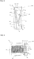
- Fig. 6 is a side cross-sectional view for illustrating an external structure and internal structure of an indoor unit 100B according to Variation 1 of Embodiment 1 not belonging to the present invention.
- Fig. 7 is a schematic diagram for illustrating a mounting position of the refrigerant leakage sensor 6A in the indoor unit 100B according to Variation 1 of Embodiment 1 not belonging to the present invention. Referring to Fig. 6 and Fig. 7 , Variation 1 of Embodiment 1 will be described hereunder focusing on a difference from Embodiment 1.
- the refrigerant leakage sensor 6A is disposed on the way of the air passage R1, like the refrigerant leakage sensor 6A in the indoor unit 100 according to Embodiment 1.
- the refrigerant leakage sensor 6A is mounted on the support portion 1G, so as to be positioned downstream of the indoor heat exchanger 3 in the airflow direction and upstream of the indoor fan 2 in the airflow direction. With the refrigerant leakage sensor 6A thus positioned, the refrigerant which has migrated to the region downstream of the indoor heat exchanger 3 can be detected, when the refrigerant leaks out in the casing 1.
- the refrigerant leaks out from the indoor heat exchanger 3 while the indoor unit 100 (indoor fan 2) is in operation, the refrigerant is caused to flow upward by operation of the indoor fan 2, so that the refrigerant leakage sensor 6A can detect the refrigerant leakage.
- the notification control unit 7B causes the notification unit 9 to output a notification
- the compressor control unit 7C stops the compressor 10.
- the rotation speed of the indoor fan 2 is increased, to diffuse the refrigerant in the casing 1 throughout the air-conditioned space.
- the indoor unit 100B can equally detect the refrigerant leakage, even when the indoor unit 100 (indoor fan 2) is out of operation.
- the refrigerant tends to reside in the lower region inside the casing of the indoor unit 100B, since the specific gravity of the refrigerant is heavier than air.
- the refrigerant which has leaked out may migrate to the upper region inside the casing of the indoor unit 100B, for example when the refrigerant spouts out of the indoor heat exchanger 3.
- the refrigerant leakage sensor 6A in the indoor unit 100B according to Variation 1 can detect the presence of the refrigerant, despite the indoor unit 100 being out of operation.
- the refrigerant may be accumulated in the casing of the indoor unit 100B, until reaching the level corresponding to the refrigerant leakage sensor 6A mounted on the support portion 1G.
- the refrigerant leakage sensor 6A can detect the presence of the refrigerant, despite the indoor unit 100 being out of operation.
- the indoor unit 100B according to Variation 1 of Embodiment 1 provides the same advantageous effects as those provided by the indoor unit 100 of the air-conditioning apparatus 200 according to Embodiment 1.
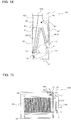
- Fig. 8 is a side cross-sectional view for illustrating an external structure and internal structure of an indoor unit 100C according to Variation 2 of Embodiment 1.
- Fig. 9 is a schematic diagram for illustrating a mounting position of the refrigerant leakage sensor 6A in the indoor unit 100C according to Variation 2 of Embodiment 1. Referring to Fig. 8 and Fig. 9 , Variation 2 of Embodiment 1 will be described hereunder focusing on a difference from Embodiment 1.
- the indoor unit 100 according to Embodiment 1 and the indoor unit 100B according to Variation 1 are combined. More specifically, the indoor unit 100C includes the refrigerant leakage sensor 6A mounted at the same position as the refrigerant leakage sensor 6A in the indoor unit 100 according to Embodiment 1, and a refrigerant leakage sensor 6B mounted at the same position as the refrigerant leakage sensor 6A in the indoor unit 100B according to Variation 1.
- the indoor unit 100C according to Variation 2 of Embodiment 1 provides the following advantageous effect, in addition to those provided by the indoor unit 100 of the air-conditioning apparatus 200 according to Embodiment 1. Since the indoor unit 100C includes the pair of refrigerant leakage sensors, even when one of the refrigerant leakage sensors is disabled by a malfunction or the like, the refrigerant leakage can still be detected by the other refrigerant leakage sensor, and therefore firing of the refrigerant can be more reliably prevented.
- Fig. 10 is a side cross-sectional view for explaining the air inlet 1B and surroundings in the indoor unit of the air-conditioning apparatus 200 according to Embodiment 2, the air inlet 1B being open.
- Fig. 11 is a side cross-sectional view for explaining the air inlet 1B and surroundings in the indoor unit of the air-conditioning apparatus 200 according to Embodiment 2, the air inlet 1B being closed.
- Fig. 12 is an enlarged side view of a pivotal element 12 of an air inlet opening and closing unit 30 shown in Fig. 10 and Fig. 11 .
- Fig. 13 is a block diagram for explaining a configuration of the controller 7 and associated components in the indoor unit of the air-conditioning apparatus 200 according to Embodiment 2.
- Embodiment 2 will be described hereunder with reference to Fig. 10 to Fig. 13 .
- the same elements as those of Embodiment 1 will be given the same numerals, and the description of Embodiment 2 will be focused on a difference from Embodiment 1.
- an air inlet opening and closing unit 30 is pivotably disposed on the air inlet 1B, in addition to the configuration of the indoor unit according to Embodiment 1.
- the controller 7 includes an opening and closing control unit 7E that rotates the air inlet opening and closing unit 30.
- the air inlet opening and closing unit 30 is pivotably disposed on the air inlet 1B.
- the air inlet opening and closing unit 30 includes a plurality of pivotal elements 12.
- the plurality of pivotal elements 12 are aligned in the up and down direction inside the casing 1.
- the pivotal elements 12 are located on the inner side of the grille 1B1.
- the pivotal elements 12 each include a flat plate-shaped portion 12A and a rotatable shaft portion 12B connected to the plate-shaped portion 12A.
- the plate-shaped portion 12A is oriented parallel to a vertical direction when closing the air inlet 1B, and parallel to a horizontal direction when opening the air inlet 1B.
- the plate-shaped portion 12A is assumed to be oriented parallel to the vertical and horizontal directions, the plate-shaped portion 12A may be deviated from the vertical or horizontal direction.
- the opening and closing control unit 7E causes the shaft portion 12B of the pivotal element 12 to rotate so as to set the plate-shaped portion 12A parallel to the horizontal direction, thereby opening the air inlet opening and closing unit 30 as shown in Fig. 10 .
- the opening and closing control unit 7E causes the shaft portion 12B of the pivotal element 12 to rotate so as to set the plate-shaped portion 12A parallel to the vertical direction as shown in Fig. 11 .
- the air inlet opening and closing unit 30 serves to facilitate the refrigerant concentration inside the casing 1 to increase, thereby facilitating the refrigerant leakage sensor 6A to more surely detect the refrigerant leakage.
- the rotation speed control unit 7D activates the indoor fan 2.
- the rotation speed of the indoor fan 2 may be set, for example, to a maximum rotation speed.
- the opening and closing control unit 7E controls the air inlet opening and closing unit 30 so as to open the air inlet 1B.
- the indoor unit of the air-conditioning apparatus 200 according to Embodiment 2 provides the following advantageous effect, in addition to those provided by the indoor unit 100 of the air-conditioning apparatus 200 according to Embodiment 1.
- the indoor unit of the air-conditioning apparatus 200 causes the air inlet opening and closing unit 30 to close the air inlet 1B when the indoor unit is out of operation, and therefore, in particular the detection accuracy of the refrigerant leakage sensor 6A with respect to refrigerant leakage can be improved.
- the air inlet opening and closing unit 30 is opened and the indoor fan 2 is activated. Accordingly, an increase in refrigerant concentration inside the casing 1 is suppressed, thereby avoiding a situation in which a fire may break out.
- Embodiment 3 not belonging to the present invention.
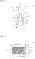
- Fig. 14 is a side cross-sectional view for illustrating an external structure and internal structure of an indoor unit 103 of the air-conditioning apparatus 200 according to Embodiment 3.
- Fig. 15 is a schematic diagram for illustrating a mounting position of the refrigerant leakage sensor 6A in the indoor unit 103 of the air-conditioning apparatus 200 according to Embodiment 3. Referring to Fig. 14 and Fig. 15 , Embodiment 3 will be described hereunder. In Embodiment 3, the same elements as those of Embodiments 1 and 2 will be given the same numerals, and the description of Embodiment 3 will be focused on a difference from Embodiments 1 and 2.
- the air inlet 1B is located on the upper side of the casing 1, and the air outlet 1A is located on the lower side of the casing 1, unlike in Embodiments 1 and 2.
- the positional relationship between the air inlet 1B and the air outlet 1A is reversed in Embodiment 3, with respect to Embodiments 1 and 2.
- the indoor unit 103 includes the casing 1 constituting the outer shell, the indoor fan 2 located in a lower region in the casing 1, the indoor heat exchanger 3 including the first heat exchanger 3A and the second heat exchanger 3B, and the filter 5 that captures dust or the like.
- the indoor unit 103 includes the refrigerant leakage sensor 6A for detecting the refrigerant leaking out in the casing 1.
- the casing 1 includes a top face 1 DD against which the upper end portion of the filter 5 is abutted, the sloped portion 1E including a sloped surface inclined downward from the front side toward the rear side, the support portion 1G and the support portion 1J each supporting a lower end portion of the indoor heat exchanger 3.
- the indoor fan 2 is located downstream of the indoor heat exchanger 3 in the airflow direction, for example at a position below the indoor heat exchanger 3.
- the indoor heat exchanger 3 is installed in the casing 1 such that the respective upper end portions of the first heat exchanger 3A and the second heat exchanger 3B are located close to each other and the respective lower end portions of the first heat exchanger 3A and the second heat exchanger 3B are spaced from each other.
- the filter 5 is obliquely installed such that the upper end portion recedes backward from the front side of the casing 1.
- the refrigerant leakage sensor 6A is located inside the casing 1 at a position above the uppermost portion of the indoor heat exchanger 3. In other words, the refrigerant leakage sensor 6A is located upstream of the indoor heat exchanger 3 in the airflow direction.
- the indoor unit 103 of the air-conditioning apparatus 200 according to Embodiment 3 provides the same advantageous effects as those provided by the indoor unit 100 of the air-conditioning apparatus 200 according to Embodiment 1.
- the configuration of, for example, the air inlet opening and closing unit 30 described in Embodiment 2 may also be incorporated in the air inlet 1B in the indoor unit 103 of the air-conditioning apparatus 200 according to Embodiment 3.
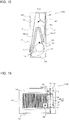
- Fig. 16 is a side cross-sectional view for illustrating an external structure and internal structure of an indoor unit 103B according to Variation 1 of Embodiment 3.
- Fig. 17 is a schematic diagram for illustrating a mounting position of the refrigerant leakage sensor 6A in the indoor unit 103B according to Variation 1 of Embodiment 3. Referring to Fig. 16 and Fig. 17 , Variation 1 of Embodiment 3 will be described hereunder focusing on a difference from Embodiment 3.
- Variation 1 of Embodiment 3 corresponds to Variation 1 of Embodiment 1.
- the refrigerant leakage sensor 6A is located at a position lower than the air inlet 1B, and below the position (summit) where the first heat exchanger 3A and the second heat exchanger 3B are brought close to each other.
- the refrigerant leakage sensor 6A is located right above the indoor fan 2.
- the refrigerant leakage sensor 6A is mounted on the support portion 1G so as to be located downstream of the indoor heat exchanger 3 in the airflow direction and upstream of the indoor fan 2 in the airflow direction.
- the indoor unit 103B according to Variation 1 of Embodiment 3 provides the same advantageous effects as those provided by Variation 1 of Embodiment 1.
- Fig. 18 is a side cross-sectional view for illustrating an external structure and internal structure of an indoor unit 103C according to Variation 2 of Embodiment 3.
- Fig. 19 is a schematic diagram for illustrating a mounting position of the refrigerant leakage sensor 6A in the indoor unit 103C according to Variation 2 of Embodiment 3. Referring to Fig. 18 and Fig. 19 , Variation 2 of Embodiment 3 will be described hereunder focusing on a difference from Embodiment 3.
- Variation 2 of Embodiment 3 corresponds to Variation 2 of Embodiment 1.
- the indoor unit 103 according to Embodiment 3 and the indoor unit 103B according to Variation 1 are combined. More specifically, the indoor unit 103C includes the refrigerant leakage sensor 6A mounted at the same position as the refrigerant leakage sensor 6A in the indoor unit 103 according to Embodiment 3, and the refrigerant leakage sensor 6B mounted at the same position as the refrigerant leakage sensor 6A in the indoor unit 103B according to Variation 1. With the mentioned configuration, the same advantageous effects as those provided by Variation 2 of Embodiment 1 can be obtained.
- Fig. 20 is a side cross-sectional view for illustrating an external structure and internal structure of an indoor unit 104 of the air-conditioning apparatus 200 according to Embodiment 4.
- Fig. 21 is a schematic diagram for illustrating a mounting position of the refrigerant leakage sensor 6A in the indoor unit 104 of the air-conditioning apparatus 200 according to Embodiment 4. Referring to Fig. 20 and Fig. 21 , Embodiment 4 will be described hereunder. In Embodiment 4, the same elements as those of Embodiments 1 to 3 will be given the same numerals, and the description of Embodiment 4 will be focused on a difference from Embodiments 1 to 3.
- the air inlet 1B is formed in a central portion of the front face of the casing 1, unlike in Embodiments 1 to 3.
- one air outlet 1A is provided at each of the upper and lower portions of the casing 1.
- the indoor unit 104 includes the casing 1 including the air inlet 1B and the pair of air outlets 1A arranged such that the air inlet 1B is located between one of the air outlets 1A and the other air outlet 1A, the indoor heat exchanger 3 disposed inside the casing 1 so as to oppose the grille 1B1 provided in the air inlet 1B, an indoor fan 2A disposed inside the casing 1 to discharge air through the upper air outlet 1A and an indoor fan 2B disposed inside the casing 1 to discharge air through the lower air outlet 1A, the refrigerant leakage sensor 6A located between the air inlet 1B and the indoor heat exchanger 3 to detect refrigerant leakage, and the controller 7 that determines whether the refrigerant leakage occurs according to the detection result of the refrigerant leakage sensor 6A.
- the casing 1 includes the air inlet 1B formed in the central portion of the front face.
- the grille 1B1 of the air inlet 1B is opposed to the indoor heat exchanger 3.
- the air inlet 1B is larger than that of the indoor units according to Embodiments 1 to 3.
- the area of the air inlet 1B is, for example, approximately equal to the area of the indoor heat exchanger 3 viewed from the front side.
- the air inlet 1B may be formed in a different size.
- the casing 1 includes the pair of air outlets 1A respectively located in the upper and lower portions.
- the upper air outlet 1A is provided with a louver 1A1 and a louver 1A2 which are pivotable.
- the lower air outlet 1A is provided with a pivotable louver 1A3.
- the louver 1A1, the louver 1A2, and the louver 1A3 allow the direction of air blown out of the casing 1 to be adjusted, and allow the air outlet 1A to be closed, to thereby prevent intrusion of dust or the like into the air passage R1 in the casing 1.
- the casing 1 includes a curved portion 1K.
- the curved portion 1K is located so as to oppose the rear face of the indoor heat exchanger 3.
- the curved portion 1K includes a convex portion 1K1 formed so as to protrude forward from the rear side. Accordingly, the curved portion 1K is capable of splitting the air which has passed through the indoor heat exchanger 3 into a flow directed to the indoor fan 2A and a flow directed to the indoor fan 2B, without incurring an increase in pressure loss.
- the curved portion 1K includes concave portions 1K2 respectively formed on the upper and lower sides of the convex portion 1K1.
- the concave portions 1K2 are each formed so as to recede backward from the front side.
- the upper concave portion 1K2 can smoothly guide the air toward the indoor fan 2A, because of having a curved surface.
- the lower concave portion 1K2 can smoothly guide the air toward the indoor fan 2B, because of having a curved surface.
- the indoor fan 2A is located downstream of the indoor heat exchanger 3 in the airflow direction, for example at a position opposing an upper portion of the rear face of the indoor heat exchanger 3.
- the indoor fan 2B is located downstream of the indoor heat exchanger 3 in the airflow direction, for example at a position opposing a lower portion of the rear face of the indoor heat exchanger 3.
- the indoor heat exchanger 3 does not include a pair of heat exchangers, unlike in Embodiments 1 to 3. In other words, in Embodiment 4 the indoor heat exchanger 3 includes a single heat exchange unit. The indoor heat exchanger 3 is oriented in a vertical direction.
- the refrigerant leakage sensor 6A is located between the grille 1B1 of the air inlet 1B and the indoor heat exchanger 3, so as to oppose a lower portion of the front face of the indoor heat exchanger 3.
- the refrigerant leakage sensor 6A is located upstream of the indoor heat exchanger 3 in the airflow direction.
- the indoor unit 104 of the air-conditioning apparatus 200 according to Embodiment 4 provides the same advantageous effects as those provided by the indoor units 100 and 103 of the air-conditioning apparatus 200 according to Embodiments 1 and 3.
- the configuration of, for example, the air inlet opening and closing unit 30 described in Embodiment 2 may also be incorporated in the air inlet 1B in the indoor unit 104 of the air-conditioning apparatus 200 according to Embodiment 4.
- Fig. 22 is a side cross-sectional view for illustrating an external structure and internal structure of an indoor unit 104B according to Variation 1 of Embodiment 4.
- Fig. 23 is a schematic diagram for illustrating a mounting position of the refrigerant leakage sensor 6A in the indoor unit 104B according to Variation 1 of Embodiment 4. Referring to Fig. 22 and Fig. 23 , Variation 1 of Embodiment 4 will be described hereunder focusing on a difference from Embodiment 4.
- Variation 1 of Embodiment 4 is different from Embodiment 4 in that the refrigerant leakage sensor 6A is mounted on the curved portion 1K.
- the refrigerant tends to reside in the lower region inside the casing 1 of the indoor unit 104B, since the specific gravity of the refrigerant is heavier than air. For such reason the refrigerant leakage sensor 6A is disposed at a lower end portion of the curved portion 1K.
- the refrigerant leakage sensor 6A is located on the rear side of the indoor heat exchanger 3. In other words, the refrigerant leakage sensor 6A is located downstream of the indoor heat exchanger 3 in the airflow direction.
- the indoor unit 104B according to Variation 1 of Embodiment 4 also provides the same advantageous effects as those provided by the indoor unit 104 of the air-conditioning apparatus 200 according to Embodiment 4.
- Fig. 24 is a side cross-sectional view for illustrating an external structure and internal structure of an indoor unit 104C according to Variation 2 of Embodiment 4.
- Fig. 25 is a schematic diagram for illustrating a mounting position of the refrigerant leakage sensor 6A in the indoor unit 104C according to Variation 2 of Embodiment 4. Referring to Fig. 24 and Fig. 25 , Variation 2 of Embodiment 4 will be described hereunder focusing on a difference from Embodiment 4.
- the indoor unit 104 according to Embodiment 4 and the indoor unit 104B according to Variation 1 are combined. More specifically, the indoor unit 104C includes the refrigerant leakage sensor 6A mounted at the same position as the refrigerant leakage sensor 6A in the indoor unit 104 according to Embodiment 4, and the refrigerant leakage sensor 6B mounted at the same position as the refrigerant leakage sensor 6A in the indoor unit 104B according to Variation 1.
- the indoor unit 104C according to Variation 2 of Embodiment 4 includes the pair of refrigerant leakage sensors, even when one of the refrigerant leakage sensors is disabled by a malfunction or the like, the refrigerant leakage can still be detected by the other refrigerant leakage sensor, and therefore firing of the refrigerant can be more reliably prevented.
- 1 casing, 1A: air outlet, 1A1: louver, 1A2: louver, 1A3: louver, 1B: air inlet, 1B1: grille, 1C: front panel, 1D: bottom face, 1DD: top face, 1E: sloped portion, 1F: upright portion, 1G: support portion, 1H: curved portion, 1J: support portion, 1K: curved portion, 1K1: convex portion, 1K2: concave portion, 2: indoor fan, 2A: indoor fan, 2B: indoor fan, 3: indoor heat exchanger, 3A: first heat exchanger, 3B: second heat exchanger, 4: drain pan, 5: filter, 6A: refrigerant leakage sensor, 6B: refrigerant leakage sensor, 7: controller, 7A: leakage determination unit, 7B: notification control unit, 7B: notification control unit, 7B: notification control unit, 7B: notification control unit, 7B: notification control unit, 7B: notification control unit, 7B: notification control unit, 7B
Description
- The present invention relates to an indoor unit of an air-conditioning apparatus including a refrigerant leakage detector, and to an air-conditioning apparatus including such an indoor unit.
- In air-conditioning apparatuses, R410A which is a HFC refrigerant has thus far been mainly employed as refrigerant to circulate in a refrigerant circuit. Although R410A has zero ozone layer depletion potential (ODP) and hence makes no harm to the ozone layer unlike conventional HCFC refrigerants such as R22, R410A has high global warming potential (GWP). Accordingly, the HFC refrigerant having high GWP such as R410A is being gradually replaced with other HFC refrigerants having low GWP, from the viewpoint of global warming prevention.
- Examples of the HFC refrigerants having low GWP include halogenated hydrocarbon containing a carbon double bond in the composition, typically exemplified by HFO-1234yf (CF3CF=CH2; tetrafluoropropane), HFO-1234ze (CF3-CH=CHF), and HFO-1123 (CF2=CHF). Although those refrigerants belong to the group of HFC refrigerants, these refrigerants are often called HFO, where O represents olefin, because unsaturated hydrocarbon containing a carbon double bond is called olefin. Therefore, the refrigerants described above will be denoted as HFO refrigerants, for distinction from the HFC refrigerants that do not contain a carbon double bond in the composition, such as R32 (CH2F2; difluoromethane) and R125 (CHF2-CF3; pentafluoroethane) contained in R410A.
- Although the HFO refrigerant having low GWP may be employed in the form of a single refrigerant, the HFO refrigerant may also be employed in the form of a mixed refrigerant containing a plurality of types of other refrigerants including a HFC refrigerant such as R32. Although the HFO refrigerant, or a mixed refrigerant containing the HFO refrigerant and the HFC refrigerant is not as highly flammable as a HC refrigerant such as R290 (C3H8; propane), such refrigerant is slightly flammable unlike R410A which is non-flammable. Accordingly, refrigerant leakage has to be taken care of. The refrigerants that have flammability, from low flammable ones to highly flammable ones, will hereinafter be called flammable refrigerants. R32 exhibits low flammability like HFO refrigerants, when used in the form of a single refrigerant. Therefore R32 is a flammable refrigerant, and consequently the mixed refrigerant containing the HFO refrigerant and R32 is also regarded as a flammable refrigerant. However, R410A which is a mixture of R32 and R125 is non-flammable owing to the characteristic of R125.
- In case that such flammable refrigerant leaks out into room air and resides in the room without diffusing, a gas phase of flammable concentration may be generated in the room, and therefore in case that an ignition source is present in the gas phase of flammable concentration, the refrigerant may catch fire. As first step for avoiding combustion of the refrigerant which has leaked out into the room, the refrigerant leakage has to be detected by the air-conditioning apparatus.
-
Patent Literature 2 discloses an air conditioner with two leakage detection sensors. An indoor unit according to the preamble ofclaim 1 is disclosed inPatent Literature 3. -
- Patent Literature 1: Japanese Unexamined Patent Application Publication No.
2002-98393 page 5, andFig. 1 and Fig. 2 ) - Patent Literature 2:
WO 2013/038704 A1 - Patent Literature 3:
US 5 769 707 A - In some indoor units (floor-mounted indoor units), an air inlet and an air outlet are positioned opposite to those of the indoor unit of the air-conditioning apparatus according to
Patent Literature 1, in an up and down direction. More specifically, some indoor units include an indoor unit casing in which the air inlet is located lower than the air outlet. - Now, with a location of a gas sensor as described in
Patent Literature 1, the refrigerant leakage may be unable to be detected when the refrigerant leaks out between the air inlet and a heat exchanger or the air outlet. - In addition, with the location of the gas sensor as described in
Patent Literature 1, it takes a long time before the gas sensor located on an outer surface of the casing detects the refrigerant leakage, when the refrigerant which has leaked out between the air inlet and the air outlet is discharged through the air outlet into the room space. Further, a highly sensitive gas sensor has to be employed since the refrigerant which has leaked out and diffused in the room space has to be detected. - The present invention has been accomplished in view of the foregoing problem, and provides an indoor unit of an air-conditioning apparatus capable of more reliably detecting refrigerant leakage while an indoor fan is out of operation, and an air-conditioning apparatus including such an indoor unit.
- In one embodiment, the present invention provides an indoor unit according to
claim 1. The indoor unit for an air-conditioning apparatus includes a casing including an air inlet, an air outlet, and an air passage communicating between the air inlet and the air outlet, the air inlet being located lower than the air outlet, an indoor heat exchanger disposed inside the casing, a drain pan disposed under the indoor heat exchanger and inside the casing; an indoor fan disposed inside the casing at a downstream side of the indoor heat exchanger in an airflow direction and at an upper position of the indoor heat exchanger and configured to supply air to the indoor heat exchanger, the indoor unit being a floor-mountable indoor unit; a filter disposed inside the casing and being located on a front side of the drain pan, wherein the filter is obliquely installed such that the lower end portion recedes backwards from the front side of the casing, a first refrigerant leakage sensor disposed in the air passage between the air inlet and the air outlet at a position lower than the drain pan and the air outlet, and configured to detect refrigerant leakage, and a controller configured to determine whether refrigerant leakage occurs according to a detection result of the refrigerant leakage sensor, wherein the casing includes a sloped portion
having a sloped surface inclined upward from a front side toward a rear side and forming a part of the air passage,
the sloped portion is located lower than the indoor heat exchange and the drain pan and is formed so as to allow the air introduced into the casing through the air inlet to smoothly flow toward the indoor heat exchanger along the sloped surface, and
the first refrigerant leakage sensor is located on the sloped portion, wherein a front end of the sloped portion is connected to a bottom face and an upper end of the sloped portion is connected to an upright portion and the upright portion is located on the rear side with respect to the indoor heat exchanger and the drain pan and extends toward a support portion from the upper end of the sloped portion. - The indoor unit of the air-conditioning apparatus according to one embodiment of the present invention includes the casing in which the air inlet is located lower than the air outlet, and the first refrigerant sensor is located lower than the indoor heat exchanger inside the casing. The mentioned configuration enables the refrigerant leakage to be more reliably detected while the indoor fan is out of operation.
-
-
Fig. 1 is a diagram for illustrating a refrigerant circuit configuration of an air-conditioning apparatus 200 according toEmbodiment 1 of the present invention. -
Fig. 2 is a schematic diagram for illustrating anindoor unit 100 of the air-conditioning apparatus 200 according toEmbodiment 1 of the present invention. -
Fig. 3 is a side cross-sectional view for illustrating an external structure and internal structure of theindoor unit 100 shown inFig. 2 . -
Fig. 4 is a schematic diagram for illustrating a mounting position of arefrigerant leakage sensor 6A in theindoor unit 100. -
Fig. 5 is a block diagram for explaining a configuration of acontroller 7 and associated components in theindoor unit 100 of the air-conditioning apparatus 200 according toEmbodiment 1 of the present invention. -
Fig. 6 is a side cross-sectional view for illustrating an external structure and internal structure of anindoor unit 100B according toVariation 1 ofEmbodiment 1 not belonging to the present invention. -
Fig. 7 is a schematic diagram for illustrating a mounting position of therefrigerant leakage sensor 6A in theindoor unit 100B according toVariation 1 ofEmbodiment 1 not belonging to the present invention. -
Fig. 8 is a side cross-sectional view for illustrating an external structure and internal structure of anindoor unit 100C according toVariation 2 ofEmbodiment 1 of the present invention. -
Fig. 9 is a schematic diagram for illustrating a mounting position of therefrigerant leakage sensor 6A in theindoor unit 100C according toVariation 2 ofEmbodiment 1 of the present invention. -
Fig. 10 is a side cross-sectional view for explaining anair inlet 1B and surroundings in the indoor unit of the air-conditioning apparatus 200 according toEmbodiment 2 of the present invention, theair inlet 1B being open. -
Fig. 11 is a side cross-sectional view for explaining theair inlet 1B and surroundings in the indoor unit of the air-conditioning apparatus 200 according toEmbodiment 2 of the present invention, theair inlet 1B being closed. -
Fig. 12 is an enlarged side view of apivotal element 12 of an air inlet opening andclosing unit 30 shown inFig. 10 and Fig. 11 . -
Fig. 13 is a block diagram for explaining a configuration of thecontroller 7 and associated components in the indoor unit of the air-conditioning apparatus 200 according toEmbodiment 2 of the present invention. -
Fig. 14 is a side cross-sectional view for illustrating an external structure and internal structure of anindoor unit 103 of the air-conditioning apparatus 200 according toEmbodiment 3 not belonging to the present invention. -
Fig. 15 is a schematic diagram for illustrating a mounting position of therefrigerant leakage sensor 6A in theindoor unit 103 of the air-conditioning apparatus 200 according toEmbodiment 3 not belonging to the present invention. -
Fig. 16 is a side cross-sectional view for illustrating an external structure and internal structure of anindoor unit 103B according toVariation 1 ofEmbodiment 3 not belonging to the present invention. -
Fig. 17 is a schematic diagram for illustrating a mounting position of therefrigerant leakage sensor 6A in theindoor unit 103B according toVariation 1 ofEmbodiment 3 not belonging to the present invention. -
Fig. 18 is a side cross-sectional view for illustrating an external structure and internal structure of anindoor unit 103C according toVariation 2 ofEmbodiment 3 not belonging to the present invention. -
Fig. 19 is a schematic diagram for illustrating a mounting position of therefrigerant leakage sensor 6A in theindoor unit 103C according toVariation 2 ofEmbodiment 3 not belonging to the present invention. -
Fig. 20 is a side cross-sectional view for illustrating an external structure and internal structure of anindoor unit 104 of the air-conditioning apparatus 200 according toEmbodiment 4 not belonging to the present invention. -
Fig. 21 is a schematic diagram for illustrating a mounting position of therefrigerant leakage sensor 6A in theindoor unit 104 of the air-conditioning apparatus 200 according toEmbodiment 4 not belonging to the present invention. -
Fig. 22 is a side cross-sectional view for illustrating an external structure and internal structure of anindoor unit 104B according toVariation 1 ofEmbodiment 4 not belonging to the present invention. -
Fig. 23 is a schematic diagram for illustrating a mounting position of therefrigerant leakage sensor 6A in theindoor unit 104B according toVariation 1 ofEmbodiment 4 not belonging to the present invention. -
Fig. 24 is a side cross-sectional view for illustrating an external structure and internal structure of anindoor unit 104C according toVariation 2 ofEmbodiment 4 not belonging to the present invention. -
Fig. 25 is a schematic diagram for illustrating a mounting position of therefrigerant leakage sensor 6A in theindoor unit 104C according toVariation 2 ofEmbodiment 4 not belonging to the present invention. - Hereafter, Embodiments of an indoor unit of an air-conditioning apparatus according to the present invention will be described with reference to the drawings. Embodiments described hereunder are not intended to limit the present invention. In
Fig. 1 and other drawings, dimensional relations among the elements illustrated in the drawings may differ from actual ones. -
Fig. 1 is a diagram for illustrating a refrigerant circuit configuration of the air-conditioning apparatus 200 according toEmbodiment 1 of the present invention. Referring toFig. 1 , a configuration or the like of the air-conditioning apparatus 200 will be described. - The
indoor unit 100 of the air-conditioning apparatus 200 according toEmbodiment 1 includes a modification that enables more reliable detection of refrigerant leakage while anindoor fan 2 is in operation and out of operation. - The air-
conditioning apparatus 200 includes, as shown inFig. 1 , theindoor unit 100 to be installed in an air-conditioned space (indoor, a room in a building, or a warehouse), and anoutdoor unit 150 to be installed outside the air-conditioned space. The air-conditioning apparatus 200 includes a refrigerant circuit C including theindoor unit 100, theoutdoor unit 150, and a refrigerant pipe connecting therebetween. - The air-
conditioning apparatus 200 also includes acompressor 10 that compresses refrigerant, aflow switching valve 11 for switching between, for example, a cooling operation and a heating operation, anoutdoor heat exchanger 16 that serves as a condenser (radiator) in the cooling operation and as an evaporator in the heating operation, anexpansion device 13 that depressurizes the refrigerant, and anindoor heat exchanger 3 that serves as an evaporator in the cooling operation and as a condenser in the heating operation. Theoutdoor heat exchanger 16 is provided with anoutdoor fan 16A that expedites the heat exchange between air and the refrigerant. - Here, the refrigerant employed in the air-
conditioning apparatus 200 will be described. - A flammable refrigerant is charged in the refrigerant circuit C. Examples of the flammable refrigerant that may be employed include an HFO1234yf-based single refrigerant, a mixed refrigerant containing a tetrafluoropropene-based refrigerant, and a flammable refrigerant such as a hydrocarbon-based refrigerant.
-
Fig. 2 is a schematic diagram for illustrating theindoor unit 100 of the air-conditioning apparatus 200 according toEmbodiment 1.Fig. 3 is a side cross-sectional view for illustrating an external structure and internal structure of theindoor unit 100 shown inFig. 2 .Fig. 4 is a schematic diagram for illustrating a mounting position of arefrigerant leakage sensor 6A in theindoor unit 100.Fig. 5 is a block diagram for explaining a configuration of acontroller 7 and associated components in theindoor unit 100 of the air-conditioning apparatus 200 according toEmbodiment 1. Referring toFig. 2 to Fig. 5 , a configuration of theindoor unit 100 will be described. - The
indoor unit 100 includes, as shown inFig. 2 , acasing 1 constituting an outer shell, anindoor fan 2 disposed inside thecasing 1, anindoor heat exchanger 3 including afirst heat exchanger 3A and asecond heat exchanger 3B, adrain pan 4 for collecting dews stuck to theindoor heat exchanger 3, and afilter 5 for capturing dust or the like. - The
indoor unit 100 also includes arefrigerant leakage sensor 6A for detecting the refrigerant leaking out in thecasing 1, anelectric parts box 18 containing thecontroller 7 that controls various components, adisplay panel 8 for displaying various information, such as an indication that theindoor unit 100 is in operation, and apartition plate 17 dividing between an air passage R1 and a space R2 in thecasing 1. The space R2 is utilized for placing theelectric parts box 18 and other components. - The
casing 1 has an outer shell of, for example, a rectangular parallelepiped shape, and the air passage R1 formed to allow air flow. Thecasing 1 includes anair outlet 1A for discharging air therethrough and anair inlet 1B for introducing air therethrough. In thecasing 1, theair inlet 1B, thefilter 5, theindoor heat exchanger 3, theindoor fan 2, and theair outlet 1A are located in this order from an upstream side in the airflow direction. Theair inlet 1B is provided with a grille 1B1 horizontally extending in parallel. The grille 1B1 serves to prevent, for example, a person's hand or finger from being inserted in theair inlet 1B. Theair outlet 1A includes a louver 1A1 and a louver 1A2 which are pivotably disposed. With the louver 1A1 and the louver 1A2, the direction of air discharged by operation of theindoor fan 2 can be adjusted. In addition, when theindoor unit 100 is out of operation theair outlet 1A can be closed with the louver 1A1 and the louver 1A2, to prevent intrusion of dust or the like into the air passage in thecasing 1. - The
casing 1 includes afront panel 1C constituting a part of the front face of theindoor unit 100, abottom face 1 D against which the lower end portion of thefilter 5 is abutted, a slopedportion 1E including a sloped surface, anupright portion 1F continuously extending upward from the slopedportion 1E, asupport portion 1G and asupport portion 1J each supporting an upper end portion of theindoor heat exchanger 3, and acurved portion 1H including a curved surface. - The surface (front face) of the
front panel 1C represents the design of theindoor unit 100, and the back surface (rear face) of thefront panel 1C is opposed to thefilter 5. Theair inlet 1B is located on the lower side of the lower end portion of thefront panel 1C, and thedisplay panel 8 is located on the upper side of the upper end portion of thefront panel 1C. The lower face of thebottom face 1D is in contact with the floor of the air-conditioned space, and the upper face of thebottom face 1 D is in contact with the lower end portion of thefilter 5. The grille 1B1 formed in theair inlet 1B is located on the upper face of the front end portion of thebottom face 1D. The rear end portion of thebottom face 1D is abutted against the slopedportion 1E. - The sloped
portion 1E includes a sloped surface inclined upward from the front side toward the rear side. Therefrigerant leakage sensor 6A is mounted on the sloped surface of the slopedportion 1E. The front end of the slopedportion 1E is connected to thebottom face 1D, and the upper end of the sloped surface of the slopedportion 1E is connected to theupright portion 1F. The slopedportion 1E is formed so as to allow the air introduced into thecasing 1 through theair inlet 1B to smoothly flow toward theindoor heat exchanger 3 along the sloped surface. Theupright portion 1 F is located on the rear side with respect to the indoor heat exchanger 3 (first heat exchanger 3A) and thedrain pan 4, and extends toward thesupport portion 1G from the upper end of the slopedportion 1E. - The
support portion 1G, thesupport portion 1 J, and thecurved portion 1H are located around theindoor fan 2. Thesupport portion 1G is disposed on the upper end of theupright portion 1F, to support the upper end portion of thefirst heat exchanger 3A. Thesupport portion 1J is disposed at the height position of the upper end of thefront panel 1C, to support the upper end portion of thesecond heat exchanger 3B. Thecurved portion 1H is formed in a predetermined curved shape, to allow the air supplied from theindoor fan 2 to be smoothly discharged outward from thecasing 1. - The
indoor fan 2 includes, for example, a cross flow fan and a motor that drives the cross flow fan, and serves to introduce air into thecasing 1 and discharge the air out of thecasing 1. Theindoor fan 2 is located downstream of theindoor heat exchanger 3. In addition, theindoor fan 2 is disposed at an upper position of theindoor heat exchanger 3. - The
indoor heat exchanger 3 includes afirst heat exchanger 3A and asecond heat exchanger 3B. Thefirst heat exchanger 3A and thesecond heat exchanger 3B are disposed inside thecasing 1 so as to form a V shape. To be more detailed, thefirst heat exchanger 3A and thesecond heat exchanger 3B are installed in thecasing 1 such that the respective lower end portions of thefirst heat exchanger 3A and thesecond heat exchanger 3B are located close to each other and the respective upper end portions of thefirst heat exchanger 3A and thesecond heat exchanger 3B are spaced from each other. The lower end portions of thefirst heat exchanger 3A and thesecond heat exchanger 3B are located above thedrain pan 4. The upper end portion of thefirst heat exchanger 3A is supported by thesupport portion 1G, and the upper end portion of thesecond heat exchanger 3B is supported by thesupport portion 1 J. - The
indoor heat exchanger 3 may be constituted of, for example, a fin-and-tube heat exchanger. Theindoor heat exchanger 3 is connected to theoutdoor heat exchanger 16 disposed in theoutdoor unit 150, via a refrigerant pipe P. The refrigerant pipe P is routed from the side of the air passage R1 to the side of the space R2. - The
drain pan 4 collects dews stuck to theindoor heat exchanger 3. Therefrigerant leakage sensor 6A mounted on the slopedportion 1E is located below thedrain pan 4, and theindoor heat exchanger 3 is located above thedrain pan 4. In addition, thefilter 5 is located on the front side of thedrain pan 4. - The
filter 5 serves to capture dust or the like in the air introduced into thecasing 1 through theair inlet 1B. Thefilter 5 is obliquely installed such that the lower end portion recedes backward from the front side of thecasing 1. - The
refrigerant leakage sensor 6A serves to detect the presence of the refrigerant residing in the lower region in thecasing 1, when the refrigerant leaks out in thecasing 1. Therefrigerant leakage sensor 6A is disposed on the way of the air passage R1. Therefrigerant leakage sensor 6A is mounted on the slopedportion 1E located below theindoor heat exchanger 3. Generally the flammable refrigerant is heavier than air, and therefore when the refrigerant leaks out, for example owing to damage in a portion located inside thecasing 1 of the refrigerant pipe connected to theindoor heat exchanger 3, the refrigerant flows to the region below theindoor heat exchanger 3. Accordingly, therefrigerant leakage sensor 6A can detect the refrigerant which has moved to the region below theindoor heat exchanger 3. Therefrigerant leakage sensor 6A may be based on, for example, oxygen concentration detection or flammable gas detection. - The
refrigerant leakage sensor 6A is connected to thecontroller 7 via a wiring CA, so that the detection result of therefrigerant leakage sensor 6A is outputted to thecontroller 7. Therefrigerant leakage sensor 6A is disposed close to thepartition plate 17. In other words, therefrigerant leakage sensor 6A is disposed on near the right-hand end of the air passage R1, in a front view of thecasing 1. Such a configuration decreases the length of a portion of the wiring CA located inside the air passage R1, thereby suppressing an increase in pressure loss originating from collision of air flowing in the air passage R1 with the wiring CA. The mentioned configuration also facilitates the connection between therefrigerant leakage sensor 6A and thecontroller 7, which also facilitates, for example, maintenance work. Further, since the length of the wiring CA can be reduced, the wiring CA can be prevented from being tangled up. - The
electric parts box 18 is disposed in the space R2 defined by thepartition plate 17 and thecasing 1. Theelectric parts box 18 contains thecontroller 7 that executes various control operations and other electric components. Thecontroller 7 determines whether refrigerant leakage occurs, according to the detection result of therefrigerant leakage sensor 6A. Thecontroller 7 then controls anotification unit 9, thecompressor 10, and other components to be subsequently described, on the basis of the determination result. - The
controller 7 includes aleakage determination unit 7A to which the detection result of therefrigerant leakage sensor 6A is outputted, anotification control unit 7B that causes thenotification unit 9 to output a notification, acompressor control unit 7C that stops thecompressor 10, and a rotationspeed control unit 7D that increases the rotation speed of theindoor fan 2. - The
leakage determination unit 7A determines whether refrigerant leakage occurs on the basis of an output (for example, voltage) from therefrigerant leakage sensor 6A. Theleakage determination unit 7A determines that the refrigerant leakage occurs when therefrigerant leakage sensor 6A detects the presence of the refrigerant. Theleakage determination unit 7A determines that the refrigerant leakage has occurred, for example, when the output from therefrigerant leakage sensor 6A varies so as to reach a first predetermined range. Here, therefrigerant leakage sensor 6A is intended to detect the refrigerant residing in the lower region in thecasing 1 while theindoor fan 2 is out of operation. - The
notification control unit 7B causes thenotification unit 9 to output a notification when theleakage determination unit 7A determines that the refrigerant leakage occurs. The user can be notified that the refrigerant leakage has occurred when thenotification unit 9 outputs the notification. In the case where the air-conditioning apparatus 200 is, for example, a multi-air-conditioning apparatus for building, the output from thenotification control unit 7B may be transmitted to a central control room or a similar section. - The
compressor control unit 7C stops thecompressor 10 when theleakage determination unit 7A determines that the refrigerant leakage occurs. In case that thecompressor 10 continues to operate when the refrigerant leaks out, for example owing to a damage in theindoor heat exchanger 3, the amount of refrigerant leakage is increased. Therefore, thecompressor 10 is stopped to suppress the amount of refrigerant leakage, when it is determined that refrigerant leakage occurs. - The rotation
speed control unit 7D increases the rotation speed of theindoor fan 2, when it is determined that refrigerant leakage occurs while the indoor unit 100 (indoor fan 2) is in operation. Here, the rotationspeed control unit 7D may control theindoor fan 2 so as to increase the rotation speed from the rotation speed in the current operation, or to set the rotation speed to a predetermined rotation speed (e.g., maximum rotation speed). - In addition, the rotation
speed control unit 7D activates theindoor fan 2, when it is determined that refrigerant leakage occurs while the indoor unit 100 (indoor fan 2) is out of operation. In this case, the rotationspeed control unit 7D may control theindoor fan 2 to rotate, for example, at a maximum rotation speed. - The rotation
speed control unit 7D can diffuse the refrigerant which has leaked out in thecasing 1 to the air-conditioned space by performing above described control. Such a configuration prevents a break out of fire due to a spark originating from short circuit of an electric part, which may occur owing to an increase in refrigerant concentration inside thecasing 1. - The
display panel 8 is located, for example, in an upper portion of thecasing 1. Thedisplay panel 8 includes adisplay screen 8A for displaying information such as the cooling operation, the heating operation, and a target temperature. Thedisplay panel 8 also includes thenotification unit 9. - The
notification unit 9 includes alamp 9A and aspeaker 9B. Thelamp 9A is lit up in red, or blinks in red upon receipt of notification of refrigerant leakage from thenotification control unit 7B, thereby notifying the user that the refrigerant leakage has occurred. Thespeaker 9B outputs, upon receipt of a notification of refrigerant leakage from thenotification control unit 7B, an audible message to this effect. The position of thenotification unit 9 is not limited to the above. For example, thenotification unit 9 may be disposed at a position on thefront panel 1C. - The
partition plate 17 is a plate-shaped member that divides the space in thecasing 1 into a left-hand space (air passage R1) and a right-hand space (space R2), in a front view of thecasing 1. To be more detailed, thepartition plate 17 serves as a partition between the air passage R1 in which theindoor fan 2 and theindoor heat exchanger 3 are located and through which the air introduced through theair inlet 1B and blown out through theair outlet 1A flows, and the space R2 in which theelectric parts box 18 and the refrigerant pipe P are located. The refrigerant pipe P located in the space R2 is connected to the refrigerant pipe drawn from the side of theoutdoor unit 150. In other words, the space R2 includes the pipe joint section, where the pipes are connected to each other. - The presence of the
partition plate 17 prevents an increase in pressure loss which caused by the air introduced into thecasing 1 through theair inlet 1B flowing into the space where theelectric parts box 18 and other components are located. Thepartition plate 17 includes an opening H for passing therethrough the wiring CA connecting between therefrigerant leakage sensor 6A and thecontroller 7. Thepartition plate 17 also includes openings for passing therethrough the refrigerant pipe P. - First, the case where the refrigerant has leaked out of the
indoor heat exchanger 3 while the indoor unit 100 (indoor fan 2) is out of operation will be described. When a single refrigerant HFO1234-yf is employed for example, the density of this refrigerant is approximately 1.1 [g/cm3], which is heavier than air. In addition, there is no circulation of the indoor air caused by theindoor fan 2. Accordingly, the refrigerant which has leaked out flows downward to the region below theindoor heat exchanger 3 in thecasing 1. Therefore, the refrigerant leakage is detected mainly by therefrigerant leakage sensor 6A. - When the
leakage determination unit 7A determines that the refrigerant leakage occurs according to the detection result of therefrigerant leakage sensor 6A, thenotification control unit 7B causes thenotification unit 9 to output a notification, and thecompressor control unit 7C stops thecompressor 10. Further, the rotationspeed control unit 7D activates theindoor fan 2 to thereby diffuse the refrigerant in thecasing 1 throughout the air-conditioned space. - In the
indoor unit 100 of the air-conditioning apparatus 200 according toEmbodiment 1, theair inlet 1B is located on the lower side of thecasing 1, and theair outlet 1A is located on the upper side of thecasing 1. In addition, therefrigerant leakage sensor 6A is located below theindoor heat exchanger 3 in thecasing 1. - Therefore, when the refrigerant leaks out while the
indoor unit 100 is out of operation, the flammable refrigerant which is heavier than air moves downward from the leakage point, so that therefrigerant leakage sensor 6A detects the refrigerant leakage. In contrast, when the refrigerant leaks out while theindoor unit 100 is in operation, the refrigerant is discharged through theair outlet 1A and diffused in the air-conditioned space together with air, by operation of theindoor fan 2. Even when the refrigerant concentration increases in the air-conditioned space, the presence of the refrigerant can be detected by the refrigerant leakage sensor because the air in the air-conditioned space is introduced through the air inlet. Thus, theindoor unit 100 of the air-conditioning apparatus 200 according toEmbodiment 1 is capable of detecting the refrigerant leakage irrespective of whether or not theindoor fan 2 is in operation. In other words, theindoor unit 100 of the air-conditioning apparatus 200 according toEmbodiment 1 is capable of more reliably detecting the refrigerant leakage, both when theindoor fan 2 is in operation and when theindoor fan 2 is out of operation. - Although the
indoor unit 100 of the air-conditioning apparatus 200 according toEmbodiment 1 is exemplified by a floor-mounted indoor unit, theindoor unit 100 may be of a different type. The same advantageous effects as those provided by theindoor unit 100 of the air-conditioning apparatus 200 according toEmbodiment 1 can be obtained, for example, from a wall-mounted indoor unit. -
Fig. 6 is a side cross-sectional view for illustrating an external structure and internal structure of anindoor unit 100B according toVariation 1 ofEmbodiment 1 not belonging to the present invention.Fig. 7 is a schematic diagram for illustrating a mounting position of therefrigerant leakage sensor 6A in theindoor unit 100B according toVariation 1 ofEmbodiment 1 not belonging to the present invention. Referring toFig. 6 and Fig. 7 ,Variation 1 ofEmbodiment 1 will be described hereunder focusing on a difference fromEmbodiment 1. - A difference between the
indoor unit 100 according toEmbodiment 1 and theindoor unit 100B according toVariation 1 lies in the mounting position of therefrigerant leakage sensor 6A. InVariation 1, therefrigerant leakage sensor 6A is disposed on the way of the air passage R1, like therefrigerant leakage sensor 6A in theindoor unit 100 according toEmbodiment 1. InVariation 1, however, therefrigerant leakage sensor 6A is mounted on thesupport portion 1G, so as to be positioned downstream of theindoor heat exchanger 3 in the airflow direction and upstream of theindoor fan 2 in the airflow direction. With therefrigerant leakage sensor 6A thus positioned, the refrigerant which has migrated to the region downstream of theindoor heat exchanger 3 can be detected, when the refrigerant leaks out in thecasing 1. - When the refrigerant leaks out from the
indoor heat exchanger 3 while the indoor unit 100 (indoor fan 2) is in operation, the refrigerant is caused to flow upward by operation of theindoor fan 2, so that therefrigerant leakage sensor 6A can detect the refrigerant leakage. - When the
leakage determination unit 7A determines that the refrigerant leakage occurs according to the detection result of therefrigerant leakage sensor 6A, thenotification control unit 7B causes thenotification unit 9 to output a notification, and thecompressor control unit 7C stops thecompressor 10. In addition, when the refrigerant leakage is detected while theindoor unit 100 is in operation, the rotation speed of theindoor fan 2 is increased, to diffuse the refrigerant in thecasing 1 throughout the air-conditioned space. - Although the foregoing description refers to the case where the indoor unit 100 (indoor fan 2) is in operation, the
indoor unit 100B can equally detect the refrigerant leakage, even when the indoor unit 100 (indoor fan 2) is out of operation. - Generally the refrigerant tends to reside in the lower region inside the casing of the
indoor unit 100B, since the specific gravity of the refrigerant is heavier than air. However, the refrigerant which has leaked out may migrate to the upper region inside the casing of theindoor unit 100B, for example when the refrigerant spouts out of theindoor heat exchanger 3. In such a case, therefrigerant leakage sensor 6A in theindoor unit 100B according toVariation 1 can detect the presence of the refrigerant, despite theindoor unit 100 being out of operation. - When the leakage amount of the refrigerant increases, the refrigerant may be accumulated in the casing of the
indoor unit 100B, until reaching the level corresponding to therefrigerant leakage sensor 6A mounted on thesupport portion 1G. In this case also, therefrigerant leakage sensor 6A can detect the presence of the refrigerant, despite theindoor unit 100 being out of operation. - Thus, the
indoor unit 100B according toVariation 1 ofEmbodiment 1 provides the same advantageous effects as those provided by theindoor unit 100 of the air-conditioning apparatus 200 according toEmbodiment 1. -
Fig. 8 is a side cross-sectional view for illustrating an external structure and internal structure of anindoor unit 100C according toVariation 2 ofEmbodiment 1.Fig. 9 is a schematic diagram for illustrating a mounting position of therefrigerant leakage sensor 6A in theindoor unit 100C according toVariation 2 ofEmbodiment 1. Referring toFig. 8 and Fig. 9 ,Variation 2 ofEmbodiment 1 will be described hereunder focusing on a difference fromEmbodiment 1. - In
Variation 2 ofEmbodiment 1, theindoor unit 100 according toEmbodiment 1 and theindoor unit 100B according toVariation 1 are combined. More specifically, theindoor unit 100C includes therefrigerant leakage sensor 6A mounted at the same position as therefrigerant leakage sensor 6A in theindoor unit 100 according toEmbodiment 1, and arefrigerant leakage sensor 6B mounted at the same position as therefrigerant leakage sensor 6A in theindoor unit 100B according toVariation 1. - The
indoor unit 100C according toVariation 2 ofEmbodiment 1 provides the following advantageous effect, in addition to those provided by theindoor unit 100 of the air-conditioning apparatus 200 according toEmbodiment 1. Since theindoor unit 100C includes the pair of refrigerant leakage sensors, even when one of the refrigerant leakage sensors is disabled by a malfunction or the like, the refrigerant leakage can still be detected by the other refrigerant leakage sensor, and therefore firing of the refrigerant can be more reliably prevented. -
Fig. 10 is a side cross-sectional view for explaining theair inlet 1B and surroundings in the indoor unit of the air-conditioning apparatus 200 according toEmbodiment 2, theair inlet 1B being open.Fig. 11 is a side cross-sectional view for explaining theair inlet 1B and surroundings in the indoor unit of the air-conditioning apparatus 200 according toEmbodiment 2, theair inlet 1B being closed.Fig. 12 is an enlarged side view of apivotal element 12 of an air inlet opening andclosing unit 30 shown inFig. 10 and Fig. 11 .Fig. 13 is a block diagram for explaining a configuration of thecontroller 7 and associated components in the indoor unit of the air-conditioning apparatus 200 according toEmbodiment 2. -
Embodiment 2 will be described hereunder with reference toFig. 10 to Fig. 13 . InEmbodiment 2, the same elements as those ofEmbodiment 1 will be given the same numerals, and the description ofEmbodiment 2 will be focused on a difference fromEmbodiment 1. - When the refrigerant leaks out while the indoor unit is out of operation, the refrigerant diffuses in the air-conditioned space through the
air inlet 1B. Accordingly, the refrigerant concentration is less likely to increase around therefrigerant leakage sensor 6A, which may lead to degraded detection accuracy of the refrigerant leakage. InEmbodiment 2, therefore, an air inlet opening andclosing unit 30 is pivotably disposed on theair inlet 1B, in addition to the configuration of the indoor unit according toEmbodiment 1. In addition, thecontroller 7 includes an opening andclosing control unit 7E that rotates the air inlet opening andclosing unit 30. - The air inlet opening and
closing unit 30 is pivotably disposed on theair inlet 1B. The air inlet opening andclosing unit 30 includes a plurality ofpivotal elements 12. The plurality ofpivotal elements 12 are aligned in the up and down direction inside thecasing 1. Thepivotal elements 12 are located on the inner side of the grille 1B1. - The
pivotal elements 12 each include a flat plate-shapedportion 12A and arotatable shaft portion 12B connected to the plate-shapedportion 12A. The plate-shapedportion 12A is oriented parallel to a vertical direction when closing theair inlet 1B, and parallel to a horizontal direction when opening theair inlet 1B. Here, although the plate-shapedportion 12A is assumed to be oriented parallel to the vertical and horizontal directions, the plate-shapedportion 12A may be deviated from the vertical or horizontal direction. - When the indoor unit is in operation, the opening and
closing control unit 7E causes theshaft portion 12B of thepivotal element 12 to rotate so as to set the plate-shapedportion 12A parallel to the horizontal direction, thereby opening the air inlet opening andclosing unit 30 as shown inFig. 10 . - In contrast, when the indoor unit is out of operation, the opening and
closing control unit 7E causes theshaft portion 12B of thepivotal element 12 to rotate so as to set the plate-shapedportion 12A parallel to the vertical direction as shown inFig. 11 . Accordingly, in case that the refrigerant leaks out while the indoor unit is out of operation, the air inlet opening andclosing unit 30 serves to facilitate the refrigerant concentration inside thecasing 1 to increase, thereby facilitating therefrigerant leakage sensor 6A to more surely detect the refrigerant leakage. - When the refrigerant leakage is detected while the indoor unit is out of operation, the rotation
speed control unit 7D activates theindoor fan 2. The rotation speed of theindoor fan 2 may be set, for example, to a maximum rotation speed. In addition, the opening andclosing control unit 7E controls the air inlet opening andclosing unit 30 so as to open theair inlet 1B. With such operation, the refrigerant in thecasing 1 can be diffused in the air-conditioned space, and therefore the increase in refrigerant concentration inside thecasing 1 can be suppressed. Consequently, a break out of fire due to a spark originating from short circuit of an electric part, which may occur owing to an increase in refrigerant concentration inside thecasing 1, can be prevented. - The indoor unit of the air-
conditioning apparatus 200 according toEmbodiment 2 provides the following advantageous effect, in addition to those provided by theindoor unit 100 of the air-conditioning apparatus 200 according toEmbodiment 1. - The indoor unit of the air-
conditioning apparatus 200 according toEmbodiment 2 causes the air inlet opening andclosing unit 30 to close theair inlet 1B when the indoor unit is out of operation, and therefore, in particular the detection accuracy of therefrigerant leakage sensor 6A with respect to refrigerant leakage can be improved. In addition, once the refrigerant leakage has been detected the air inlet opening andclosing unit 30 is opened and theindoor fan 2 is activated. Accordingly, an increase in refrigerant concentration inside thecasing 1 is suppressed, thereby avoiding a situation in which a fire may break out. -
Embodiment 3 not belonging to the present invention. -
Fig. 14 is a side cross-sectional view for illustrating an external structure and internal structure of anindoor unit 103 of the air-conditioning apparatus 200 according toEmbodiment 3.Fig. 15 is a schematic diagram for illustrating a mounting position of therefrigerant leakage sensor 6A in theindoor unit 103 of the air-conditioning apparatus 200 according toEmbodiment 3. Referring toFig. 14 and Fig. 15 ,Embodiment 3 will be described hereunder. InEmbodiment 3, the same elements as those ofEmbodiments Embodiment 3 will be focused on a difference fromEmbodiments - In the
indoor unit 103, theair inlet 1B is located on the upper side of thecasing 1, and theair outlet 1A is located on the lower side of thecasing 1, unlike inEmbodiments air inlet 1B and theair outlet 1A is reversed inEmbodiment 3, with respect toEmbodiments - The
indoor unit 103 includes thecasing 1 constituting the outer shell, theindoor fan 2 located in a lower region in thecasing 1, theindoor heat exchanger 3 including thefirst heat exchanger 3A and thesecond heat exchanger 3B, and thefilter 5 that captures dust or the like. In addition, theindoor unit 103 includes therefrigerant leakage sensor 6A for detecting the refrigerant leaking out in thecasing 1. - The
casing 1 includes atop face 1 DD against which the upper end portion of thefilter 5 is abutted, the slopedportion 1E including a sloped surface inclined downward from the front side toward the rear side, thesupport portion 1G and thesupport portion 1J each supporting a lower end portion of theindoor heat exchanger 3. - The
indoor fan 2 is located downstream of theindoor heat exchanger 3 in the airflow direction, for example at a position below theindoor heat exchanger 3. - The
indoor heat exchanger 3 is installed in thecasing 1 such that the respective upper end portions of thefirst heat exchanger 3A and thesecond heat exchanger 3B are located close to each other and the respective lower end portions of thefirst heat exchanger 3A and thesecond heat exchanger 3B are spaced from each other. - The
filter 5 is obliquely installed such that the upper end portion recedes backward from the front side of thecasing 1. - Further, the
refrigerant leakage sensor 6A is located inside thecasing 1 at a position above the uppermost portion of theindoor heat exchanger 3. In other words, therefrigerant leakage sensor 6A is located upstream of theindoor heat exchanger 3 in the airflow direction. - The
indoor unit 103 of the air-conditioning apparatus 200 according toEmbodiment 3 provides the same advantageous effects as those provided by theindoor unit 100 of the air-conditioning apparatus 200 according toEmbodiment 1. - Here, the configuration of, for example, the air inlet opening and
closing unit 30 described inEmbodiment 2 may also be incorporated in theair inlet 1B in theindoor unit 103 of the air-conditioning apparatus 200 according toEmbodiment 3. -
Fig. 16 is a side cross-sectional view for illustrating an external structure and internal structure of anindoor unit 103B according toVariation 1 ofEmbodiment 3.Fig. 17 is a schematic diagram for illustrating a mounting position of therefrigerant leakage sensor 6A in theindoor unit 103B according toVariation 1 ofEmbodiment 3. Referring toFig. 16 and Fig. 17 ,Variation 1 ofEmbodiment 3 will be described hereunder focusing on a difference fromEmbodiment 3. -
Variation 1 ofEmbodiment 3 corresponds toVariation 1 ofEmbodiment 1. In other words, inVariation 1 ofEmbodiment 3 therefrigerant leakage sensor 6A is located at a position lower than theair inlet 1B, and below the position (summit) where thefirst heat exchanger 3A and thesecond heat exchanger 3B are brought close to each other. In addition, therefrigerant leakage sensor 6A is located right above theindoor fan 2. Further, therefrigerant leakage sensor 6A is mounted on thesupport portion 1G so as to be located downstream of theindoor heat exchanger 3 in the airflow direction and upstream of theindoor fan 2 in the airflow direction. Theindoor unit 103B according toVariation 1 ofEmbodiment 3 provides the same advantageous effects as those provided byVariation 1 ofEmbodiment 1. -
Fig. 18 is a side cross-sectional view for illustrating an external structure and internal structure of anindoor unit 103C according toVariation 2 ofEmbodiment 3.Fig. 19 is a schematic diagram for illustrating a mounting position of therefrigerant leakage sensor 6A in theindoor unit 103C according toVariation 2 ofEmbodiment 3. Referring toFig. 18 and Fig. 19 ,Variation 2 ofEmbodiment 3 will be described hereunder focusing on a difference fromEmbodiment 3. -
Variation 2 ofEmbodiment 3 corresponds toVariation 2 ofEmbodiment 1. In other words, inVariation 2 ofEmbodiment 3 theindoor unit 103 according toEmbodiment 3 and theindoor unit 103B according toVariation 1 are combined. More specifically, theindoor unit 103C includes therefrigerant leakage sensor 6A mounted at the same position as therefrigerant leakage sensor 6A in theindoor unit 103 according toEmbodiment 3, and therefrigerant leakage sensor 6B mounted at the same position as therefrigerant leakage sensor 6A in theindoor unit 103B according toVariation 1. With the mentioned configuration, the same advantageous effects as those provided byVariation 2 ofEmbodiment 1 can be obtained. -
Fig. 20 is a side cross-sectional view for illustrating an external structure and internal structure of anindoor unit 104 of the air-conditioning apparatus 200 according toEmbodiment 4.Fig. 21 is a schematic diagram for illustrating a mounting position of therefrigerant leakage sensor 6A in theindoor unit 104 of the air-conditioning apparatus 200 according toEmbodiment 4. Referring toFig. 20 and Fig. 21 ,Embodiment 4 will be described hereunder. InEmbodiment 4, the same elements as those ofEmbodiments 1 to 3 will be given the same numerals, and the description ofEmbodiment 4 will be focused on a difference fromEmbodiments 1 to 3. - In the
indoor unit 104, theair inlet 1B is formed in a central portion of the front face of thecasing 1, unlike inEmbodiments 1 to 3. In addition, oneair outlet 1A is provided at each of the upper and lower portions of thecasing 1. - The
indoor unit 104 includes thecasing 1 including theair inlet 1B and the pair ofair outlets 1A arranged such that theair inlet 1B is located between one of theair outlets 1A and theother air outlet 1A, theindoor heat exchanger 3 disposed inside thecasing 1 so as to oppose the grille 1B1 provided in theair inlet 1B, anindoor fan 2A disposed inside thecasing 1 to discharge air through theupper air outlet 1A and anindoor fan 2B disposed inside thecasing 1 to discharge air through thelower air outlet 1A, therefrigerant leakage sensor 6A located between theair inlet 1B and theindoor heat exchanger 3 to detect refrigerant leakage, and thecontroller 7 that determines whether the refrigerant leakage occurs according to the detection result of therefrigerant leakage sensor 6A. - The
casing 1 includes theair inlet 1B formed in the central portion of the front face. The grille 1B1 of theair inlet 1B is opposed to theindoor heat exchanger 3. InEmbodiment 4, theair inlet 1B is larger than that of the indoor units according toEmbodiments 1 to 3. InEmbodiment 4, the area of theair inlet 1B is, for example, approximately equal to the area of theindoor heat exchanger 3 viewed from the front side. However, theair inlet 1B may be formed in a different size. - The
casing 1 includes the pair ofair outlets 1A respectively located in the upper and lower portions. Theupper air outlet 1A is provided with a louver 1A1 and a louver 1A2 which are pivotable. Thelower air outlet 1A is provided with a pivotable louver 1A3. The louver 1A1, the louver 1A2, and the louver 1A3 allow the direction of air blown out of thecasing 1 to be adjusted, and allow theair outlet 1A to be closed, to thereby prevent intrusion of dust or the like into the air passage R1 in thecasing 1. - The
casing 1 includes acurved portion 1K. Thecurved portion 1K is located so as to oppose the rear face of theindoor heat exchanger 3. Thecurved portion 1K includes a convex portion 1K1 formed so as to protrude forward from the rear side. Accordingly, thecurved portion 1K is capable of splitting the air which has passed through theindoor heat exchanger 3 into a flow directed to theindoor fan 2A and a flow directed to theindoor fan 2B, without incurring an increase in pressure loss. In addition, thecurved portion 1K includes concave portions 1K2 respectively formed on the upper and lower sides of the convex portion 1K1. The concave portions 1K2 are each formed so as to recede backward from the front side. The upper concave portion 1K2 can smoothly guide the air toward theindoor fan 2A, because of having a curved surface. Likewise, the lower concave portion 1K2 can smoothly guide the air toward theindoor fan 2B, because of having a curved surface. - The
indoor fan 2A is located downstream of theindoor heat exchanger 3 in the airflow direction, for example at a position opposing an upper portion of the rear face of theindoor heat exchanger 3. Theindoor fan 2B is located downstream of theindoor heat exchanger 3 in the airflow direction, for example at a position opposing a lower portion of the rear face of theindoor heat exchanger 3. - The
indoor heat exchanger 3 does not include a pair of heat exchangers, unlike inEmbodiments 1 to 3. In other words, inEmbodiment 4 theindoor heat exchanger 3 includes a single heat exchange unit. Theindoor heat exchanger 3 is oriented in a vertical direction. - Further, the
refrigerant leakage sensor 6A is located between the grille 1B1 of theair inlet 1B and theindoor heat exchanger 3, so as to oppose a lower portion of the front face of theindoor heat exchanger 3. Therefrigerant leakage sensor 6A is located upstream of theindoor heat exchanger 3 in the airflow direction. - The
indoor unit 104 of the air-conditioning apparatus 200 according toEmbodiment 4 provides the same advantageous effects as those provided by theindoor units conditioning apparatus 200 according toEmbodiments - Here, the configuration of, for example, the air inlet opening and
closing unit 30 described inEmbodiment 2 may also be incorporated in theair inlet 1B in theindoor unit 104 of the air-conditioning apparatus 200 according toEmbodiment 4. -
Fig. 22 is a side cross-sectional view for illustrating an external structure and internal structure of anindoor unit 104B according toVariation 1 ofEmbodiment 4.Fig. 23 is a schematic diagram for illustrating a mounting position of therefrigerant leakage sensor 6A in theindoor unit 104B according toVariation 1 ofEmbodiment 4. Referring toFig. 22 and Fig. 23 ,Variation 1 ofEmbodiment 4 will be described hereunder focusing on a difference fromEmbodiment 4. -
Variation 1 ofEmbodiment 4 is different fromEmbodiment 4 in that therefrigerant leakage sensor 6A is mounted on thecurved portion 1K. The refrigerant tends to reside in the lower region inside thecasing 1 of theindoor unit 104B, since the specific gravity of the refrigerant is heavier than air. For such reason therefrigerant leakage sensor 6A is disposed at a lower end portion of thecurved portion 1K. Such a configuration allows the refrigerant leakage to be more reliably detected. Therefrigerant leakage sensor 6A is located on the rear side of theindoor heat exchanger 3. In other words, therefrigerant leakage sensor 6A is located downstream of theindoor heat exchanger 3 in the airflow direction. Theindoor unit 104B according toVariation 1 ofEmbodiment 4 also provides the same advantageous effects as those provided by theindoor unit 104 of the air-conditioning apparatus 200 according toEmbodiment 4. -
Fig. 24 is a side cross-sectional view for illustrating an external structure and internal structure of anindoor unit 104C according toVariation 2 ofEmbodiment 4.Fig. 25 is a schematic diagram for illustrating a mounting position of therefrigerant leakage sensor 6A in theindoor unit 104C according toVariation 2 ofEmbodiment 4. Referring toFig. 24 and Fig. 25 ,Variation 2 ofEmbodiment 4 will be described hereunder focusing on a difference fromEmbodiment 4. - In
Variation 2 ofEmbodiment 4, theindoor unit 104 according toEmbodiment 4 and theindoor unit 104B according toVariation 1 are combined. More specifically, theindoor unit 104C includes therefrigerant leakage sensor 6A mounted at the same position as therefrigerant leakage sensor 6A in theindoor unit 104 according toEmbodiment 4, and therefrigerant leakage sensor 6B mounted at the same position as therefrigerant leakage sensor 6A in theindoor unit 104B according toVariation 1. - Since the
indoor unit 104C according toVariation 2 ofEmbodiment 4 includes the pair of refrigerant leakage sensors, even when one of the refrigerant leakage sensors is disabled by a malfunction or the like, the refrigerant leakage can still be detected by the other refrigerant leakage sensor, and therefore firing of the refrigerant can be more reliably prevented. - 1: casing, 1A: air outlet, 1A1: louver, 1A2: louver, 1A3: louver, 1B: air inlet, 1B1: grille, 1C: front panel, 1D: bottom face, 1DD: top face, 1E: sloped portion, 1F: upright portion, 1G: support portion, 1H: curved portion, 1J: support portion, 1K: curved portion, 1K1: convex portion, 1K2: concave portion, 2: indoor fan, 2A: indoor fan, 2B: indoor fan, 3: indoor heat exchanger, 3A: first heat exchanger, 3B: second heat exchanger, 4: drain pan, 5: filter, 6A: refrigerant leakage sensor, 6B: refrigerant leakage sensor, 7: controller, 7A: leakage determination unit, 7B: notification control unit, 7C: compressor control unit, 7D: rotation speed control unit, 7E: opening and closing control unit, 8: display panel, 8A: display screen, 9: notification unit, 9A: lamp, 9B: speaker, 10: compressor, 11: flow switching valve, 12: pivotal element, 12A: plate-shaped portion, 12B: shaft portion, 13: expansion device, 16: outdoor heat exchanger, 16A: outdoor fan, 17: partition plate, 18: electric parts box, 30: air inlet opening and closing unit, 100: indoor unit, 100B: indoor unit, 100C: indoor unit, 103: indoor unit, 103B: indoor unit, 103C: indoor unit, 104: indoor unit, 104B: indoor unit, 104C: indoor unit, 150: outdoor unit, 200: air-conditioning apparatus, C: refrigerant circuit, CA: wiring, H: opening, P: refrigerant pipe, R1: air passage, R2: space
Claims (11)
- An indoor unit (100, 100C) for an air-conditioning apparatus, comprising:a controller (7);a casing (1) including an air inlet (1 B), an air outlet (1A), and an air passage (R1) communicating between the air inlet (1B) and the air outlet (1A), the air inlet (1B) being located lower than the air outlet (1A);an indoor heat exchanger (3) disposed inside the casing (1);a drain pan (4) disposed under the indoor heat exchanger (3) and inside the casing (1);an indoor fan (2, 2A, 2B) disposed (1) at a downstream side of the indoor heat exchanger (3) in an airflow direction and inside the casing (1) and at an upper position of the indoor heat exchanger (3), and configured to supply air to the indoor heat exchanger (3), the indoor unit (100, 100C) being a floor-mountable indoor unit; anda filter (5) disposed inside the casing (1) and being located on a front side of the drain pan (4), characterized by the filter (5) being obliquely installed such that the lower end portion recedes backwards from the front side of the casing (1);a first refrigerant leakage sensor (6A) disposed in the air passage (R1) between the air inlet (1B) and the air outlet (1A) at a position lower than the drain pan (4) and the air outlet (1A), and configured to detect refrigerant leakage; and said controller (7) being configured to determine whether refrigerant leakage occurs, according to a detection result of the first refrigerant leakage sensor (6A), wherein the casing (1) includes a sloped portion (1E) having a sloped surface inclined upward from a front side toward a rear side and forming a part of the air passage (R1),the sloped portion (1 E) is located lower than the indoor heat exchanger (3) and the drain pan (4) and is formed so as to allow the air introduced into the casing (1) through the air inlet (1B) to smoothly flow toward the indoor heat exchanger (3) along the sloped surface, andthe first refrigerant leakage sensor (6A) is located on the sloped portion (1 E), wherein a front end of the sloped portion (1 E) is connected to a bottom face (1D) and an upper end of the sloped portion (1E) is connected to an upright portion (1F) and the upright portion (1F) is located on the rear side with respect to the indoor heat exchanger (3) and the drain pan (4) and extends toward a support portion (1G) from the upper end of the sloped portion (1E).
- The indoor unit (100, 100C) of claim 1, further comprising a second refrigerant leakage sensor (6B) mounted on the support portion (1G), so as to be disposed in the air passage (R1) between the air inlet (1B) and the air outlet (1A) at the downstream side of the indoor heat exchanger (3) in the airflow direction and the upstream side of the indoor fan (9) in the air-flow direction, and configured to detect refrigerant leakage,
wherein the controller (7) is configured to determine whether refrigerant leakage occurs, according to the detection result of the first refrigerant leakage sensor (6A) and a detection result of the second refrigerant leakage sensor (6B). - The indoor unit (100, 100C) of claim 1 or 2,
wherein, upon determining that refrigerant leakage occurs, the controller (7) is configured to increase rotation speed of the indoor fan (2, 2A, 2B), when the indoor fan (2, 2A, 2B) is in operation. - The indoor unit (100, 100C) of claim 1 or 2,
wherein, upon determining that refrigerant leakage occurs, the controller (7) is configured to activate the indoor fan (2, 2A, 2B) when the indoor fan (2, 2A, 2B) is out of operation. - The indoor unit (100, 100C) of claim 4, further comprising an air inlet opening and closing unit (30) attached to the air inlet (1B) and configured to open and close the air inlet (1B),
wherein the controller (7) is configured to cause the air inlet opening and closing unit (30) to close the air inlet (1B) when the indoor fan (2, 2A, 2B) is out of operation. - The indoor unit (100, 100C) of claim 5,
wherein, upon determining that refrigerant leakage occurs, the controller (7) is configured to activate the indoor fan (2, 2A, 2B), and to cause the air inlet opening and closing unit (30) to open the air inlet (1B). - The indoor unit (100, 100C) of any one of claims 1 to 6, further comprising a notification unit (9) to be utilized to notify occurrence of refrigerant leakage,
wherein the controller (7) is configured to cause the notification unit (9) to output a notification, upon determining that refrigerant leakage occurs. - The indoor unit (100, 100C) of claim 7,
wherein the notification unit (9) includes a sound output unit disposed in the casing (1) and configured to output an audible message notifying the occurrence of the refrigerant leakage. - An air-conditioning apparatus (200) comprising a refrigerant circuit (C) including the indoor unit (100, 100C) of any one of claims 1 to 8, and an outdoor unit (150) connected to the indoor unit (100, 100C) via a refrigerant pipe (P).
- The air-conditioning apparatus (200) of claim 9,
wherein the outdoor unit (150) includes a compressor (10) configured to compress refrigerant, and
the controller (7) of the indoor unit (100, 100C) is configured to stop operation of the compressor (10), upon determining that refrigerant leakage occurs. - The air-conditioning apparatus (200) of claim 9 or 10,
wherein the refrigerant circuit (C) is charged with one of an HFO1234yf-based single refrigerant, a mixed refrigerant containing a tetrafluoropropene-based refrigerant, and a flammable refrigerant such as hydrocarbon-based refrigerant.
Applications Claiming Priority (2)
| Application Number | Priority Date | Filing Date | Title |
|---|---|---|---|
| JP2014126426 | 2014-06-19 | ||
| PCT/JP2015/067485 WO2015194596A1 (en) | 2014-06-19 | 2015-06-17 | Indoor unit for air-conditioning device, and air-conditioning device provided with said indoor unit |
Publications (3)
| Publication Number | Publication Date |
|---|---|
| EP3159633A1 EP3159633A1 (en) | 2017-04-26 |
| EP3159633A4 EP3159633A4 (en) | 2017-06-21 |
| EP3159633B1 true EP3159633B1 (en) | 2019-08-28 |
Family
ID=54935576
Family Applications (1)
| Application Number | Title | Priority Date | Filing Date |
|---|---|---|---|
| EP15810109.7A Active EP3159633B1 (en) | 2014-06-19 | 2015-06-17 | Indoor unit for air-conditioning device, and air-conditioning device provided with said indoor unit |
Country Status (5)
| Country | Link |
|---|---|
| US (1) | US10060645B2 (en) |
| EP (1) | EP3159633B1 (en) |
| JP (1) | JP6355734B2 (en) |
| AU (1) | AU2015277826B2 (en) |
| WO (1) | WO2015194596A1 (en) |
Families Citing this family (36)
| Publication number | Priority date | Publication date | Assignee | Title |
|---|---|---|---|---|
| WO2016151641A1 (en) * | 2015-03-26 | 2016-09-29 | 三菱電機株式会社 | Indoor unit of air conditioner |
| WO2017006462A1 (en) * | 2015-07-08 | 2017-01-12 | 三菱電機株式会社 | Air conditioner |
| JP6613734B2 (en) * | 2015-09-04 | 2019-12-04 | ダイキン工業株式会社 | Air conditioning system |
| WO2017175300A1 (en) * | 2016-04-05 | 2017-10-12 | 三菱電機株式会社 | Air conditioner |
| JP6876375B2 (en) | 2016-04-18 | 2021-05-26 | ダイキン工業株式会社 | Fan drive circuit of heat pump device |
| US10823445B2 (en) * | 2016-04-27 | 2020-11-03 | Mitsubishi Electric Corporation | Refrigeration cycle apparatus |
| JP6587743B2 (en) * | 2016-05-13 | 2019-10-09 | 三菱電機株式会社 | Air conditioner |
| CN109073260A (en) * | 2016-05-17 | 2018-12-21 | 三菱电机株式会社 | Air conditioner |
| CN106765973B (en) * | 2017-01-03 | 2020-06-30 | 青岛海尔空调器有限总公司 | Control method for fluorine deficiency detection of air conditioner and air conditioner |
| CN106839283A (en) * | 2017-01-05 | 2017-06-13 | 青岛海尔空调器有限总公司 | The detection method of coolant leakage |
| EP3569955B1 (en) * | 2017-01-11 | 2021-05-19 | Mitsubishi Electric Corporation | Refrigerated warehouse |
| JP7105538B2 (en) * | 2017-01-16 | 2022-07-25 | ダイキン工業株式会社 | Indoor unit of air conditioner |
| JP6477767B2 (en) * | 2017-03-31 | 2019-03-06 | ダイキン工業株式会社 | Refrigeration equipment |
| JP6418346B2 (en) * | 2017-03-31 | 2018-11-07 | ダイキン工業株式会社 | Method for detecting refrigerant leak location |
| EP4361510A2 (en) * | 2017-04-06 | 2024-05-01 | Carrier Corporation | Moderate-to-low global warming potential value refrigerant leak detection |
| JP6914794B2 (en) * | 2017-09-27 | 2021-08-04 | 東芝キヤリア株式会社 | Air conditioner |
| JP6610644B2 (en) * | 2017-11-20 | 2019-11-27 | ダイキン工業株式会社 | Air conditioner indoor unit |
| US20190170599A1 (en) * | 2017-12-01 | 2019-06-06 | Johnson Controls Technology Company | Systems and methods for leak management utilizing sub-barometric refrigerant conduit sleeves |
| US10935454B2 (en) * | 2017-12-01 | 2021-03-02 | Johnson Controls Technology Company | Systems and methods for refrigerant leak management |
| US10816247B2 (en) * | 2017-12-01 | 2020-10-27 | Johnson Controls Technology Company | Heating, ventilation, and air conditioning control system |
| JP6949194B2 (en) * | 2018-02-20 | 2021-10-13 | 三菱電機株式会社 | An indoor unit of an air conditioner and an air conditioner equipped with this indoor unit |
| JP6847303B2 (en) * | 2018-04-11 | 2021-03-24 | 三菱電機株式会社 | Indoor unit of air conditioner |
| SE543347C2 (en) * | 2018-06-22 | 2020-12-08 | Flaektgroup Sweden Ab | A safety system, an air handling system, a method and a computer program product for evacuation of contaminated air |
| CN112368558A (en) * | 2018-07-06 | 2021-02-12 | 开利公司 | Method and system for combustible gas detection |
| WO2020021661A1 (en) * | 2018-07-25 | 2020-01-30 | ダイキン工業株式会社 | Air conditioning system |
| WO2020110216A1 (en) * | 2018-11-28 | 2020-06-04 | 三菱電機株式会社 | Air conditioning device |
| US20220003444A1 (en) * | 2019-01-09 | 2022-01-06 | Mitsubishi Electric Corporation | Air-conditioning apparatus |
| JP6653455B1 (en) * | 2019-02-20 | 2020-02-26 | パナソニックIpマネジメント株式会社 | Indoor unit |
| JP2022527440A (en) * | 2019-04-29 | 2022-06-02 | 広東美的制冷設備有限公司 | Air conditioner indoor unit |
| US11662109B2 (en) | 2019-06-05 | 2023-05-30 | Carrier Corporation | Enclosure for gas detector |
| JP6614389B1 (en) | 2019-07-12 | 2019-12-04 | ダイキン工業株式会社 | Refrigeration equipment indoor unit |
| JP6922947B2 (en) * | 2019-07-12 | 2021-08-18 | ダイキン工業株式会社 | Indoor unit of refrigeration equipment |
| US11435101B2 (en) * | 2019-09-26 | 2022-09-06 | Rheem Manufacturing Company | Air mover refrigerant leak detection and risk mitigation |
| JP7057519B2 (en) * | 2020-02-05 | 2022-04-20 | ダイキン工業株式会社 | Air conditioning system |
| US11635339B2 (en) * | 2020-03-13 | 2023-04-25 | Honeywell International Inc. | Gas leakage monitoring system |
| EP3974735A1 (en) * | 2020-09-25 | 2022-03-30 | Daikin Industries, Ltd. | Indoor unit of a heat pump |
Family Cites Families (24)
| Publication number | Priority date | Publication date | Assignee | Title |
|---|---|---|---|---|
| US5769707A (en) * | 1995-12-12 | 1998-06-23 | Samsung Electronics Co., Ltd. | Method and apparatus for broadening an air discharge pattern from a room air conditioner |
| JPH10110971A (en) | 1996-10-08 | 1998-04-28 | Hitachi Ltd | Air conditioner having liquid crystal operating section |
| JP3733674B2 (en) * | 1997-01-30 | 2006-01-11 | 株式会社デンソー | Air conditioner |
| JPH11153372A (en) | 1997-11-20 | 1999-06-08 | Matsushita Electric Ind Co Ltd | Outdoor unit of air conditioner |
| JPH11159924A (en) | 1997-11-28 | 1999-06-15 | Matsushita Electric Ind Co Ltd | Connecting method of pipeline for air conditioner |
| JP3615039B2 (en) * | 1997-12-05 | 2005-01-26 | 松下電器産業株式会社 | Air conditioner |
| JPH11230648A (en) * | 1998-02-13 | 1999-08-27 | Matsushita Electric Ind Co Ltd | Refrigerant leakage alarm for freezing apparatus using combustible refrigerant |
| JP2001208392A (en) * | 2000-01-31 | 2001-08-03 | Matsushita Electric Ind Co Ltd | Heat pump device |
| JP4639451B2 (en) * | 2000-09-26 | 2011-02-23 | ダイキン工業株式会社 | Air conditioner |
| JP3744330B2 (en) * | 2000-09-26 | 2006-02-08 | ダイキン工業株式会社 | Air conditioner indoor unit |
| JP4599699B2 (en) | 2000-09-26 | 2010-12-15 | ダイキン工業株式会社 | Air conditioner |
| JP3986287B2 (en) | 2001-10-18 | 2007-10-03 | シャープ株式会社 | Air conditioner |
| JP2003130385A (en) | 2001-10-25 | 2003-05-08 | Sharp Corp | Air conditioner |
| US7003972B2 (en) * | 2003-11-24 | 2006-02-28 | Lg Electronics Inc. | Indoor unit for air conditioner |
| JP2006275310A (en) | 2005-03-28 | 2006-10-12 | Matsushita Electric Ind Co Ltd | Air conditioner |
| JP2011106697A (en) * | 2009-11-13 | 2011-06-02 | Mitsubishi Electric Corp | Air-conditioning indoor unit |
| JP2012013348A (en) * | 2010-07-02 | 2012-01-19 | Panasonic Corp | Air conditioner |
| KR20140064711A (en) * | 2011-09-14 | 2014-05-28 | 파나소닉 주식회사 | Air conditioner |
| JP2014224611A (en) * | 2011-09-16 | 2014-12-04 | パナソニック株式会社 | Air conditioner |
| JP2014224612A (en) | 2011-09-16 | 2014-12-04 | パナソニック株式会社 | Air conditioner |
| US9581379B2 (en) | 2012-04-06 | 2017-02-28 | Mitsubishi Electric Corporation | Floor-standing air-conditioning apparatus |
| JP5605396B2 (en) | 2012-06-21 | 2014-10-15 | 三菱電機株式会社 | ENVIRONMENTAL MONITORING DEVICE AND REFRIGERATION CYCLE DEVICE EQUIPPED WITH THE SAME |
| JP2014035171A (en) * | 2012-08-10 | 2014-02-24 | Mitsubishi Electric Corp | Air conditioner, air conditioning method and program |
| JP6349150B2 (en) * | 2014-05-28 | 2018-06-27 | 日立ジョンソンコントロールズ空調株式会社 | Air conditioner |
-
2015
- 2015-06-17 WO PCT/JP2015/067485 patent/WO2015194596A1/en active Application Filing
- 2015-06-17 EP EP15810109.7A patent/EP3159633B1/en active Active
- 2015-06-17 US US15/315,087 patent/US10060645B2/en active Active
- 2015-06-17 AU AU2015277826A patent/AU2015277826B2/en active Active
- 2015-06-17 JP JP2016529409A patent/JP6355734B2/en active Active
Non-Patent Citations (1)
| Title |
|---|
| None * |
Also Published As
| Publication number | Publication date |
|---|---|
| JP6355734B2 (en) | 2018-07-11 |
| US10060645B2 (en) | 2018-08-28 |
| US20170198936A1 (en) | 2017-07-13 |
| WO2015194596A1 (en) | 2015-12-23 |
| JPWO2015194596A1 (en) | 2017-04-20 |
| EP3159633A4 (en) | 2017-06-21 |
| AU2015277826A1 (en) | 2017-01-05 |
| AU2015277826B2 (en) | 2018-01-25 |
| EP3159633A1 (en) | 2017-04-26 |
Similar Documents
| Publication | Publication Date | Title |
|---|---|---|
| EP3159633B1 (en) | Indoor unit for air-conditioning device, and air-conditioning device provided with said indoor unit | |
| EP3264000B1 (en) | Indoor unit for air conditioner | |
| JP6233546B2 (en) | Air conditioner indoor unit | |
| JP5818849B2 (en) | Air conditioner and refrigerant leakage detection method | |
| JP6958627B2 (en) | Air conditioner | |
| JP6785883B2 (en) | Air conditioner | |
| JP7176175B2 (en) | air conditioner | |
| EP3112768B1 (en) | Air conditioner | |
| JP6065962B1 (en) | Refrigeration cycle equipment | |
| US11835244B2 (en) | Evaporator with one or more leak mitigation dampers | |
| JP6349150B2 (en) | Air conditioner | |
| JP6584649B2 (en) | Air conditioner | |
| JP2015215111A (en) | Heat pump device | |
| JP6869213B2 (en) | Air conditioner | |
| JP6914794B2 (en) | Air conditioner | |
| EP3199881B1 (en) | Refrigeration cycle device | |
| JP6272149B2 (en) | Air conditioner |
Legal Events
| Date | Code | Title | Description |
|---|---|---|---|
| STAA | Information on the status of an ep patent application or granted ep patent |
Free format text: STATUS: THE INTERNATIONAL PUBLICATION HAS BEEN MADE |
|
| PUAI | Public reference made under article 153(3) epc to a published international application that has entered the european phase |
Free format text: ORIGINAL CODE: 0009012 |
|
| STAA | Information on the status of an ep patent application or granted ep patent |
Free format text: STATUS: REQUEST FOR EXAMINATION WAS MADE |
|
| 17P | Request for examination filed |
Effective date: 20161213 |
|
| AK | Designated contracting states |
Kind code of ref document: A1 Designated state(s): AL AT BE BG CH CY CZ DE DK EE ES FI FR GB GR HR HU IE IS IT LI LT LU LV MC MK MT NL NO PL PT RO RS SE SI SK SM TR |
|
| AX | Request for extension of the european patent |
Extension state: BA ME |
|
| A4 | Supplementary search report drawn up and despatched |
Effective date: 20170523 |
|
| RIC1 | Information provided on ipc code assigned before grant |
Ipc: F24F 11/04 20060101ALI20170517BHEP Ipc: F24F 1/00 20110101ALI20170517BHEP Ipc: F24F 11/00 20060101ALI20170517BHEP Ipc: F25B 1/00 20060101ALI20170517BHEP Ipc: F25B 49/02 20060101AFI20170517BHEP |
|
| DAV | Request for validation of the european patent (deleted) | ||
| DAX | Request for extension of the european patent (deleted) | ||
| STAA | Information on the status of an ep patent application or granted ep patent |
Free format text: STATUS: EXAMINATION IS IN PROGRESS |
|
| 17Q | First examination report despatched |
Effective date: 20180306 |
|
| REG | Reference to a national code |
Ref country code: DE Ref legal event code: R079 Ref document number: 602015036848 Country of ref document: DE Free format text: PREVIOUS MAIN CLASS: F25B0049020000 Ipc: F24F0011300000 |
|
| RIC1 | Information provided on ipc code assigned before grant |
Ipc: F24F 11/30 20180101AFI20190208BHEP Ipc: F24F 11/77 20180101ALI20190208BHEP Ipc: F24F 1/005 20190101ALI20190208BHEP Ipc: F24F 11/74 20180101ALI20190208BHEP Ipc: F25B 49/02 20060101ALI20190208BHEP Ipc: F24F 110/00 20180101ALI20190208BHEP Ipc: F24F 1/0007 20190101ALI20190208BHEP |
|
| GRAP | Despatch of communication of intention to grant a patent |
Free format text: ORIGINAL CODE: EPIDOSNIGR1 |
|
| STAA | Information on the status of an ep patent application or granted ep patent |
Free format text: STATUS: GRANT OF PATENT IS INTENDED |
|
| INTG | Intention to grant announced |
Effective date: 20190327 |
|
| GRAS | Grant fee paid |
Free format text: ORIGINAL CODE: EPIDOSNIGR3 |
|
| GRAA | (expected) grant |
Free format text: ORIGINAL CODE: 0009210 |
|
| STAA | Information on the status of an ep patent application or granted ep patent |
Free format text: STATUS: THE PATENT HAS BEEN GRANTED |
|
| AK | Designated contracting states |
Kind code of ref document: B1 Designated state(s): AL AT BE BG CH CY CZ DE DK EE ES FI FR GB GR HR HU IE IS IT LI LT LU LV MC MK MT NL NO PL PT RO RS SE SI SK SM TR |
|
| REG | Reference to a national code |
Ref country code: GB Ref legal event code: FG4D |
|
| REG | Reference to a national code |
Ref country code: CH Ref legal event code: EP |
|
| REG | Reference to a national code |
Ref country code: AT Ref legal event code: REF Ref document number: 1172888 Country of ref document: AT Kind code of ref document: T Effective date: 20190915 |
|
| REG | Reference to a national code |
Ref country code: IE Ref legal event code: FG4D |
|
| REG | Reference to a national code |
Ref country code: DE Ref legal event code: R096 Ref document number: 602015036848 Country of ref document: DE |
|
| REG | Reference to a national code |
Ref country code: NL Ref legal event code: MP Effective date: 20190828 |
|
| REG | Reference to a national code |
Ref country code: LT Ref legal event code: MG4D |
|
| PG25 | Lapsed in a contracting state [announced via postgrant information from national office to epo] |
Ref country code: FI Free format text: LAPSE BECAUSE OF FAILURE TO SUBMIT A TRANSLATION OF THE DESCRIPTION OR TO PAY THE FEE WITHIN THE PRESCRIBED TIME-LIMIT Effective date: 20190828 Ref country code: PT Free format text: LAPSE BECAUSE OF FAILURE TO SUBMIT A TRANSLATION OF THE DESCRIPTION OR TO PAY THE FEE WITHIN THE PRESCRIBED TIME-LIMIT Effective date: 20191230 Ref country code: NO Free format text: LAPSE BECAUSE OF FAILURE TO SUBMIT A TRANSLATION OF THE DESCRIPTION OR TO PAY THE FEE WITHIN THE PRESCRIBED TIME-LIMIT Effective date: 20191128 Ref country code: NL Free format text: LAPSE BECAUSE OF FAILURE TO SUBMIT A TRANSLATION OF THE DESCRIPTION OR TO PAY THE FEE WITHIN THE PRESCRIBED TIME-LIMIT Effective date: 20190828 Ref country code: LT Free format text: LAPSE BECAUSE OF FAILURE TO SUBMIT A TRANSLATION OF THE DESCRIPTION OR TO PAY THE FEE WITHIN THE PRESCRIBED TIME-LIMIT Effective date: 20190828 Ref country code: BG Free format text: LAPSE BECAUSE OF FAILURE TO SUBMIT A TRANSLATION OF THE DESCRIPTION OR TO PAY THE FEE WITHIN THE PRESCRIBED TIME-LIMIT Effective date: 20191128 Ref country code: SE Free format text: LAPSE BECAUSE OF FAILURE TO SUBMIT A TRANSLATION OF THE DESCRIPTION OR TO PAY THE FEE WITHIN THE PRESCRIBED TIME-LIMIT Effective date: 20190828 Ref country code: HR Free format text: LAPSE BECAUSE OF FAILURE TO SUBMIT A TRANSLATION OF THE DESCRIPTION OR TO PAY THE FEE WITHIN THE PRESCRIBED TIME-LIMIT Effective date: 20190828 |
|
| PG25 | Lapsed in a contracting state [announced via postgrant information from national office to epo] |
Ref country code: AL Free format text: LAPSE BECAUSE OF FAILURE TO SUBMIT A TRANSLATION OF THE DESCRIPTION OR TO PAY THE FEE WITHIN THE PRESCRIBED TIME-LIMIT Effective date: 20190828 Ref country code: RS Free format text: LAPSE BECAUSE OF FAILURE TO SUBMIT A TRANSLATION OF THE DESCRIPTION OR TO PAY THE FEE WITHIN THE PRESCRIBED TIME-LIMIT Effective date: 20190828 Ref country code: LV Free format text: LAPSE BECAUSE OF FAILURE TO SUBMIT A TRANSLATION OF THE DESCRIPTION OR TO PAY THE FEE WITHIN THE PRESCRIBED TIME-LIMIT Effective date: 20190828 Ref country code: GR Free format text: LAPSE BECAUSE OF FAILURE TO SUBMIT A TRANSLATION OF THE DESCRIPTION OR TO PAY THE FEE WITHIN THE PRESCRIBED TIME-LIMIT Effective date: 20191129 Ref country code: IS Free format text: LAPSE BECAUSE OF FAILURE TO SUBMIT A TRANSLATION OF THE DESCRIPTION OR TO PAY THE FEE WITHIN THE PRESCRIBED TIME-LIMIT Effective date: 20191228 Ref country code: ES Free format text: LAPSE BECAUSE OF FAILURE TO SUBMIT A TRANSLATION OF THE DESCRIPTION OR TO PAY THE FEE WITHIN THE PRESCRIBED TIME-LIMIT Effective date: 20190828 |
|
| REG | Reference to a national code |
Ref country code: AT Ref legal event code: MK05 Ref document number: 1172888 Country of ref document: AT Kind code of ref document: T Effective date: 20190828 |
|
| PG25 | Lapsed in a contracting state [announced via postgrant information from national office to epo] |
Ref country code: TR Free format text: LAPSE BECAUSE OF FAILURE TO SUBMIT A TRANSLATION OF THE DESCRIPTION OR TO PAY THE FEE WITHIN THE PRESCRIBED TIME-LIMIT Effective date: 20190828 |
|
| PG25 | Lapsed in a contracting state [announced via postgrant information from national office to epo] |
Ref country code: IT Free format text: LAPSE BECAUSE OF FAILURE TO SUBMIT A TRANSLATION OF THE DESCRIPTION OR TO PAY THE FEE WITHIN THE PRESCRIBED TIME-LIMIT Effective date: 20190828 Ref country code: PL Free format text: LAPSE BECAUSE OF FAILURE TO SUBMIT A TRANSLATION OF THE DESCRIPTION OR TO PAY THE FEE WITHIN THE PRESCRIBED TIME-LIMIT Effective date: 20190828 Ref country code: DK Free format text: LAPSE BECAUSE OF FAILURE TO SUBMIT A TRANSLATION OF THE DESCRIPTION OR TO PAY THE FEE WITHIN THE PRESCRIBED TIME-LIMIT Effective date: 20190828 Ref country code: EE Free format text: LAPSE BECAUSE OF FAILURE TO SUBMIT A TRANSLATION OF THE DESCRIPTION OR TO PAY THE FEE WITHIN THE PRESCRIBED TIME-LIMIT Effective date: 20190828 Ref country code: AT Free format text: LAPSE BECAUSE OF FAILURE TO SUBMIT A TRANSLATION OF THE DESCRIPTION OR TO PAY THE FEE WITHIN THE PRESCRIBED TIME-LIMIT Effective date: 20190828 Ref country code: RO Free format text: LAPSE BECAUSE OF FAILURE TO SUBMIT A TRANSLATION OF THE DESCRIPTION OR TO PAY THE FEE WITHIN THE PRESCRIBED TIME-LIMIT Effective date: 20190828 |
|
| PG25 | Lapsed in a contracting state [announced via postgrant information from national office to epo] |
Ref country code: CZ Free format text: LAPSE BECAUSE OF FAILURE TO SUBMIT A TRANSLATION OF THE DESCRIPTION OR TO PAY THE FEE WITHIN THE PRESCRIBED TIME-LIMIT Effective date: 20190828 Ref country code: SM Free format text: LAPSE BECAUSE OF FAILURE TO SUBMIT A TRANSLATION OF THE DESCRIPTION OR TO PAY THE FEE WITHIN THE PRESCRIBED TIME-LIMIT Effective date: 20190828 Ref country code: SK Free format text: LAPSE BECAUSE OF FAILURE TO SUBMIT A TRANSLATION OF THE DESCRIPTION OR TO PAY THE FEE WITHIN THE PRESCRIBED TIME-LIMIT Effective date: 20190828 Ref country code: IS Free format text: LAPSE BECAUSE OF FAILURE TO SUBMIT A TRANSLATION OF THE DESCRIPTION OR TO PAY THE FEE WITHIN THE PRESCRIBED TIME-LIMIT Effective date: 20200224 |
|
| REG | Reference to a national code |
Ref country code: DE Ref legal event code: R097 Ref document number: 602015036848 Country of ref document: DE |
|
| PLBE | No opposition filed within time limit |
Free format text: ORIGINAL CODE: 0009261 |
|
| STAA | Information on the status of an ep patent application or granted ep patent |
Free format text: STATUS: NO OPPOSITION FILED WITHIN TIME LIMIT |
|
| PG2D | Information on lapse in contracting state deleted |
Ref country code: IS |
|
| 26N | No opposition filed |
Effective date: 20200603 |
|
| PG25 | Lapsed in a contracting state [announced via postgrant information from national office to epo] |
Ref country code: SI Free format text: LAPSE BECAUSE OF FAILURE TO SUBMIT A TRANSLATION OF THE DESCRIPTION OR TO PAY THE FEE WITHIN THE PRESCRIBED TIME-LIMIT Effective date: 20190828 |
|
| PG25 | Lapsed in a contracting state [announced via postgrant information from national office to epo] |
Ref country code: MC Free format text: LAPSE BECAUSE OF FAILURE TO SUBMIT A TRANSLATION OF THE DESCRIPTION OR TO PAY THE FEE WITHIN THE PRESCRIBED TIME-LIMIT Effective date: 20190828 |
|
| REG | Reference to a national code |
Ref country code: CH Ref legal event code: PL |
|
| GBPC | Gb: european patent ceased through non-payment of renewal fee |
Effective date: 20200617 |
|
| PG25 | Lapsed in a contracting state [announced via postgrant information from national office to epo] |
Ref country code: LU Free format text: LAPSE BECAUSE OF NON-PAYMENT OF DUE FEES Effective date: 20200617 |
|
| REG | Reference to a national code |
Ref country code: BE Ref legal event code: MM Effective date: 20200630 |
|
| PG25 | Lapsed in a contracting state [announced via postgrant information from national office to epo] |
Ref country code: CH Free format text: LAPSE BECAUSE OF NON-PAYMENT OF DUE FEES Effective date: 20200630 Ref country code: GB Free format text: LAPSE BECAUSE OF NON-PAYMENT OF DUE FEES Effective date: 20200617 Ref country code: IE Free format text: LAPSE BECAUSE OF NON-PAYMENT OF DUE FEES Effective date: 20200617 Ref country code: LI Free format text: LAPSE BECAUSE OF NON-PAYMENT OF DUE FEES Effective date: 20200630 |
|
| PG25 | Lapsed in a contracting state [announced via postgrant information from national office to epo] |
Ref country code: BE Free format text: LAPSE BECAUSE OF NON-PAYMENT OF DUE FEES Effective date: 20200630 |
|
| PG25 | Lapsed in a contracting state [announced via postgrant information from national office to epo] |
Ref country code: MT Free format text: LAPSE BECAUSE OF FAILURE TO SUBMIT A TRANSLATION OF THE DESCRIPTION OR TO PAY THE FEE WITHIN THE PRESCRIBED TIME-LIMIT Effective date: 20190828 Ref country code: CY Free format text: LAPSE BECAUSE OF FAILURE TO SUBMIT A TRANSLATION OF THE DESCRIPTION OR TO PAY THE FEE WITHIN THE PRESCRIBED TIME-LIMIT Effective date: 20190828 |
|
| PG25 | Lapsed in a contracting state [announced via postgrant information from national office to epo] |
Ref country code: MK Free format text: LAPSE BECAUSE OF FAILURE TO SUBMIT A TRANSLATION OF THE DESCRIPTION OR TO PAY THE FEE WITHIN THE PRESCRIBED TIME-LIMIT Effective date: 20190828 |
|
| P01 | Opt-out of the competence of the unified patent court (upc) registered |
Effective date: 20230512 |
|
| PGFP | Annual fee paid to national office [announced via postgrant information from national office to epo] |
Ref country code: FR Payment date: 20230510 Year of fee payment: 9 Ref country code: DE Payment date: 20230502 Year of fee payment: 9 |