WO2023063398A1 - 光硬化性組成物、硬化物、積層体、硬化物の製造方法、及び、レンズの製造方法 - Google Patents
光硬化性組成物、硬化物、積層体、硬化物の製造方法、及び、レンズの製造方法 Download PDFInfo
- Publication number
- WO2023063398A1 WO2023063398A1 PCT/JP2022/038275 JP2022038275W WO2023063398A1 WO 2023063398 A1 WO2023063398 A1 WO 2023063398A1 JP 2022038275 W JP2022038275 W JP 2022038275W WO 2023063398 A1 WO2023063398 A1 WO 2023063398A1
- Authority
- WO
- WIPO (PCT)
- Prior art keywords
- group
- photocurable composition
- carbon atoms
- formula
- compound
- Prior art date
Links
- 239000000203 mixture Substances 0.000 title claims abstract description 538
- 238000004519 manufacturing process Methods 0.000 title claims description 128
- -1 (thio)cyanate compound Chemical class 0.000 claims abstract description 244
- 150000001875 compounds Chemical class 0.000 claims abstract description 230
- 229920006295 polythiol Polymers 0.000 claims abstract description 91
- 229920000582 polyisocyanurate Polymers 0.000 claims abstract description 82
- 239000011495 polyisocyanurate Substances 0.000 claims abstract description 82
- 125000004432 carbon atom Chemical group C* 0.000 claims description 160
- 125000000217 alkyl group Chemical group 0.000 claims description 137
- 239000000758 substrate Substances 0.000 claims description 105
- 238000001723 curing Methods 0.000 claims description 103
- 238000000034 method Methods 0.000 claims description 83
- 125000003118 aryl group Chemical group 0.000 claims description 81
- 125000001997 phenyl group Chemical group [H]C1=C([H])C([H])=C(*)C([H])=C1[H] 0.000 claims description 81
- 125000001624 naphthyl group Chemical group 0.000 claims description 71
- 229920001296 polysiloxane Polymers 0.000 claims description 71
- 125000002178 anthracenyl group Chemical group C1(=CC=CC2=CC3=CC=CC=C3C=C12)* 0.000 claims description 64
- 125000005561 phenanthryl group Chemical group 0.000 claims description 64
- 239000010410 layer Substances 0.000 claims description 54
- 125000000753 cycloalkyl group Chemical group 0.000 claims description 42
- 125000003342 alkenyl group Chemical group 0.000 claims description 40
- 125000005843 halogen group Chemical group 0.000 claims description 40
- 125000000623 heterocyclic group Chemical group 0.000 claims description 38
- 229910052751 metal Inorganic materials 0.000 claims description 31
- 239000002184 metal Substances 0.000 claims description 31
- 239000003054 catalyst Substances 0.000 claims description 29
- 239000003504 photosensitizing agent Substances 0.000 claims description 26
- FKTHNVSLHLHISI-UHFFFAOYSA-N 1,2-bis(isocyanatomethyl)benzene Chemical compound O=C=NCC1=CC=CC=C1CN=C=O FKTHNVSLHLHISI-UHFFFAOYSA-N 0.000 claims description 20
- 125000003545 alkoxy group Chemical group 0.000 claims description 17
- 125000001072 heteroaryl group Chemical group 0.000 claims description 17
- FOLVZNOYNJFEBK-UHFFFAOYSA-N 3,5-bis(isocyanatomethyl)bicyclo[2.2.1]heptane Chemical compound C1C(CN=C=O)C2C(CN=C=O)CC1C2 FOLVZNOYNJFEBK-UHFFFAOYSA-N 0.000 claims description 14
- 125000002723 alicyclic group Chemical group 0.000 claims description 13
- 125000004435 hydrogen atom Chemical group [H]* 0.000 claims description 13
- 238000000465 moulding Methods 0.000 claims description 13
- DGAQECJNVWCQMB-PUAWFVPOSA-M Ilexoside XXIX Chemical compound C[C@@H]1CC[C@@]2(CC[C@@]3(C(=CC[C@H]4[C@]3(CC[C@@H]5[C@@]4(CC[C@@H](C5(C)C)OS(=O)(=O)[O-])C)C)[C@@H]2[C@]1(C)O)C)C(=O)O[C@H]6[C@@H]([C@H]([C@@H]([C@H](O6)CO)O)O)O.[Na+] DGAQECJNVWCQMB-PUAWFVPOSA-M 0.000 claims description 12
- 239000012948 isocyanate Substances 0.000 claims description 12
- 239000011734 sodium Substances 0.000 claims description 12
- 229910052708 sodium Inorganic materials 0.000 claims description 12
- CEUQYYYUSUCFKP-UHFFFAOYSA-N 2,3-bis(2-sulfanylethylsulfanyl)propane-1-thiol Chemical compound SCCSCC(CS)SCCS CEUQYYYUSUCFKP-UHFFFAOYSA-N 0.000 claims description 11
- MTZUIIAIAKMWLI-UHFFFAOYSA-N 1,2-diisocyanatobenzene Chemical class O=C=NC1=CC=CC=C1N=C=O MTZUIIAIAKMWLI-UHFFFAOYSA-N 0.000 claims description 10
- DFPJRUKWEPYFJT-UHFFFAOYSA-N 1,5-diisocyanatopentane Chemical compound O=C=NCCCCCN=C=O DFPJRUKWEPYFJT-UHFFFAOYSA-N 0.000 claims description 10
- PAUHLEIGHAUFAK-UHFFFAOYSA-N 1-isocyanato-1-[(1-isocyanatocyclohexyl)methyl]cyclohexane Chemical compound C1CCCCC1(N=C=O)CC1(N=C=O)CCCCC1 PAUHLEIGHAUFAK-UHFFFAOYSA-N 0.000 claims description 10
- UPMLOUAZCHDJJD-UHFFFAOYSA-N 4,4'-Diphenylmethane Diisocyanate Chemical compound C1=CC(N=C=O)=CC=C1CC1=CC=C(N=C=O)C=C1 UPMLOUAZCHDJJD-UHFFFAOYSA-N 0.000 claims description 10
- 239000005057 Hexamethylene diisocyanate Substances 0.000 claims description 10
- 239000005058 Isophorone diisocyanate Substances 0.000 claims description 10
- RRAMGCGOFNQTLD-UHFFFAOYSA-N hexamethylene diisocyanate Chemical compound O=C=NCCCCCCN=C=O RRAMGCGOFNQTLD-UHFFFAOYSA-N 0.000 claims description 10
- NIMLQBUJDJZYEJ-UHFFFAOYSA-N isophorone diisocyanate Chemical compound CC1(C)CC(N=C=O)CC(C)(CN=C=O)C1 NIMLQBUJDJZYEJ-UHFFFAOYSA-N 0.000 claims description 10
- DVKJHBMWWAPEIU-UHFFFAOYSA-N toluene 2,4-diisocyanate Chemical compound CC1=CC=C(N=C=O)C=C1N=C=O DVKJHBMWWAPEIU-UHFFFAOYSA-N 0.000 claims description 10
- 239000006097 ultraviolet radiation absorber Substances 0.000 claims description 10
- QXRRAZIZHCWBQY-UHFFFAOYSA-N 1,1-bis(isocyanatomethyl)cyclohexane Chemical compound O=C=NCC1(CN=C=O)CCCCC1 QXRRAZIZHCWBQY-UHFFFAOYSA-N 0.000 claims description 9
- 125000003647 acryloyl group Chemical group O=C([*])C([H])=C([H])[H] 0.000 claims description 9
- 229910052736 halogen Inorganic materials 0.000 claims description 9
- OKTJSMMVPCPJKN-UHFFFAOYSA-N Carbon Chemical compound [C] OKTJSMMVPCPJKN-UHFFFAOYSA-N 0.000 claims description 7
- JOBBTVPTPXRUBP-UHFFFAOYSA-N [3-(3-sulfanylpropanoyloxy)-2,2-bis(3-sulfanylpropanoyloxymethyl)propyl] 3-sulfanylpropanoate Chemical compound SCCC(=O)OCC(COC(=O)CCS)(COC(=O)CCS)COC(=O)CCS JOBBTVPTPXRUBP-UHFFFAOYSA-N 0.000 claims description 7
- 229910052799 carbon Inorganic materials 0.000 claims description 7
- 150000002367 halogens Chemical class 0.000 claims description 7
- JRKRMWWBDZSDMT-UHFFFAOYSA-N 2-[(thiiran-2-ylmethyldisulfanyl)methyl]thiirane Chemical compound C1SC1CSSCC1CS1 JRKRMWWBDZSDMT-UHFFFAOYSA-N 0.000 claims description 6
- RUDUCNPHDIMQCY-UHFFFAOYSA-N [3-(2-sulfanylacetyl)oxy-2,2-bis[(2-sulfanylacetyl)oxymethyl]propyl] 2-sulfanylacetate Chemical compound SCC(=O)OCC(COC(=O)CS)(COC(=O)CS)COC(=O)CS RUDUCNPHDIMQCY-UHFFFAOYSA-N 0.000 claims description 6
- 125000004122 cyclic group Chemical group 0.000 claims description 6
- 150000002513 isocyanates Chemical class 0.000 claims description 6
- FDJWTMYNYYJBAT-UHFFFAOYSA-N 1,3,3-tris(sulfanylmethylsulfanyl)propylsulfanylmethanethiol Chemical compound SCSC(SCS)CC(SCS)SCS FDJWTMYNYYJBAT-UHFFFAOYSA-N 0.000 claims description 5
- LOZWAPSEEHRYPG-UHFFFAOYSA-N 1,4-dithiane Chemical group C1CSCCS1 LOZWAPSEEHRYPG-UHFFFAOYSA-N 0.000 claims description 5
- MLHBQCMRBXCFLT-UHFFFAOYSA-N 2,2-bis(sulfanylmethylsulfanyl)ethanethiol Chemical compound SCSC(CS)SCS MLHBQCMRBXCFLT-UHFFFAOYSA-N 0.000 claims description 5
- KSJBMDCFYZKAFH-UHFFFAOYSA-N 2-(2-sulfanylethylsulfanyl)ethanethiol Chemical compound SCCSCCS KSJBMDCFYZKAFH-UHFFFAOYSA-N 0.000 claims description 5
- COYTVZAYDAIHDK-UHFFFAOYSA-N [5-(sulfanylmethyl)-1,4-dithian-2-yl]methanethiol Chemical compound SCC1CSC(CS)CS1 COYTVZAYDAIHDK-UHFFFAOYSA-N 0.000 claims description 5
- QNSUVMHSJGIMDL-UHFFFAOYSA-N [6-(sulfanylmethylsulfanyl)-1,3-dithian-4-yl]sulfanylmethanethiol Chemical compound SCSC1CC(SCS)SCS1 QNSUVMHSJGIMDL-UHFFFAOYSA-N 0.000 claims description 5
- 239000012790 adhesive layer Substances 0.000 claims description 5
- 125000000732 arylene group Chemical group 0.000 claims description 5
- QWCNRESNZMCPJW-UHFFFAOYSA-N bis(sulfanylmethylsulfanyl)methylsulfanylmethanethiol Chemical compound SCSC(SCS)SCS QWCNRESNZMCPJW-UHFFFAOYSA-N 0.000 claims description 5
- 229910052801 chlorine Inorganic materials 0.000 claims description 5
- 125000001309 chloro group Chemical group Cl* 0.000 claims description 5
- UMRZSTCPUPJPOJ-KNVOCYPGSA-N norbornane Chemical compound C1C[C@H]2CC[C@@H]1C2 UMRZSTCPUPJPOJ-KNVOCYPGSA-N 0.000 claims description 5
- MLGITEWCALEOOJ-UHFFFAOYSA-N 2-(thiiran-2-ylmethylsulfanylmethyl)thiirane Chemical compound C1SC1CSCC1CS1 MLGITEWCALEOOJ-UHFFFAOYSA-N 0.000 claims description 4
- 238000000016 photochemical curing Methods 0.000 claims description 4
- NITQFNYRKUAWHQ-UHFFFAOYSA-N [2-(1,3-dithietan-2-yl)-1-(sulfanylmethylsulfanyl)ethyl]sulfanylmethanethiol Chemical compound SCSC(SCS)CC1SCS1 NITQFNYRKUAWHQ-UHFFFAOYSA-N 0.000 claims description 3
- 125000001183 hydrocarbyl group Chemical group 0.000 claims 4
- OTMSDBZUPAUEDD-UHFFFAOYSA-N Ethane Chemical compound CC OTMSDBZUPAUEDD-UHFFFAOYSA-N 0.000 claims 1
- 125000001424 substituent group Chemical group 0.000 abstract description 7
- 125000004209 (C1-C8) alkyl group Chemical group 0.000 abstract 1
- 125000006552 (C3-C8) cycloalkyl group Chemical group 0.000 abstract 1
- 239000000047 product Substances 0.000 description 253
- 239000011521 glass Substances 0.000 description 104
- 229920005989 resin Polymers 0.000 description 101
- 239000011347 resin Substances 0.000 description 101
- 239000002585 base Substances 0.000 description 87
- 230000003287 optical effect Effects 0.000 description 68
- 239000010408 film Substances 0.000 description 48
- 238000010438 heat treatment Methods 0.000 description 43
- 238000006116 polymerization reaction Methods 0.000 description 40
- 239000000126 substance Substances 0.000 description 40
- 229920003023 plastic Polymers 0.000 description 38
- 239000004033 plastic Substances 0.000 description 38
- 239000003795 chemical substances by application Substances 0.000 description 35
- 239000004810 polytetrafluoroethylene Substances 0.000 description 31
- 229920001343 polytetrafluoroethylene Polymers 0.000 description 31
- 239000000463 material Substances 0.000 description 30
- 239000000654 additive Substances 0.000 description 26
- 230000000052 comparative effect Effects 0.000 description 25
- 238000003756 stirring Methods 0.000 description 25
- 238000009281 ultraviolet germicidal irradiation Methods 0.000 description 23
- 150000002430 hydrocarbons Chemical group 0.000 description 20
- 230000000996 additive effect Effects 0.000 description 19
- 239000012298 atmosphere Substances 0.000 description 18
- 239000005056 polyisocyanate Substances 0.000 description 17
- 229920001228 polyisocyanate Polymers 0.000 description 17
- 239000004721 Polyphenylene oxide Substances 0.000 description 16
- 239000010419 fine particle Substances 0.000 description 16
- 238000002156 mixing Methods 0.000 description 16
- 229920000570 polyether Polymers 0.000 description 16
- 239000000243 solution Substances 0.000 description 16
- 238000000576 coating method Methods 0.000 description 15
- 208000001491 myopia Diseases 0.000 description 15
- 230000001629 suppression Effects 0.000 description 15
- 238000011156 evaluation Methods 0.000 description 14
- 206010020675 Hypermetropia Diseases 0.000 description 13
- 238000003848 UV Light-Curing Methods 0.000 description 13
- 201000006318 hyperopia Diseases 0.000 description 13
- KWYUFKZDYYNOTN-UHFFFAOYSA-M Potassium hydroxide Chemical compound [OH-].[K+] KWYUFKZDYYNOTN-UHFFFAOYSA-M 0.000 description 12
- 239000011248 coating agent Substances 0.000 description 12
- LEAAXJONQWQISB-UHFFFAOYSA-N 2,5-bis(isocyanatomethyl)bicyclo[2.2.1]heptane Chemical compound C1C2C(CN=C=O)CC1C(CN=C=O)C2 LEAAXJONQWQISB-UHFFFAOYSA-N 0.000 description 11
- 239000008199 coating composition Substances 0.000 description 11
- WQJONRMBVKFKOB-UHFFFAOYSA-N cyanatosulfanyl cyanate Chemical class N#COSOC#N WQJONRMBVKFKOB-UHFFFAOYSA-N 0.000 description 11
- 230000004379 myopia Effects 0.000 description 11
- VYPSYNLAJGMNEJ-UHFFFAOYSA-N Silicium dioxide Chemical compound O=[Si]=O VYPSYNLAJGMNEJ-UHFFFAOYSA-N 0.000 description 10
- 239000000853 adhesive Substances 0.000 description 10
- 230000001070 adhesive effect Effects 0.000 description 10
- 238000005530 etching Methods 0.000 description 10
- 229910052731 fluorine Inorganic materials 0.000 description 10
- 230000001678 irradiating effect Effects 0.000 description 10
- 238000002360 preparation method Methods 0.000 description 10
- 238000001816 cooling Methods 0.000 description 9
- 230000004305 hyperopia Effects 0.000 description 9
- 239000007787 solid Substances 0.000 description 9
- XLYOFNOQVPJJNP-UHFFFAOYSA-N water Substances O XLYOFNOQVPJJNP-UHFFFAOYSA-N 0.000 description 9
- 238000004090 dissolution Methods 0.000 description 8
- 229910052760 oxygen Inorganic materials 0.000 description 8
- 230000008569 process Effects 0.000 description 8
- 125000001637 1-naphthyl group Chemical group [H]C1=C([H])C([H])=C2C(*)=C([H])C([H])=C([H])C2=C1[H] 0.000 description 7
- YCKRFDGAMUMZLT-UHFFFAOYSA-N Fluorine atom Chemical compound [F] YCKRFDGAMUMZLT-UHFFFAOYSA-N 0.000 description 7
- CBENFWSGALASAD-UHFFFAOYSA-N Ozone Chemical compound [O-][O+]=O CBENFWSGALASAD-UHFFFAOYSA-N 0.000 description 7
- 239000007864 aqueous solution Substances 0.000 description 7
- QVGXLLKOCUKJST-UHFFFAOYSA-N atomic oxygen Chemical compound [O] QVGXLLKOCUKJST-UHFFFAOYSA-N 0.000 description 7
- 230000015572 biosynthetic process Effects 0.000 description 7
- PKKGKUDPKRTKLJ-UHFFFAOYSA-L dichloro(dimethyl)stannane Chemical compound C[Sn](C)(Cl)Cl PKKGKUDPKRTKLJ-UHFFFAOYSA-L 0.000 description 7
- 239000005357 flat glass Substances 0.000 description 7
- 239000011737 fluorine Substances 0.000 description 7
- 239000012528 membrane Substances 0.000 description 7
- 239000001301 oxygen Substances 0.000 description 7
- 239000011148 porous material Substances 0.000 description 7
- 238000003786 synthesis reaction Methods 0.000 description 7
- DZLFLBLQUQXARW-UHFFFAOYSA-N tetrabutylammonium Chemical compound CCCC[N+](CCCC)(CCCC)CCCC DZLFLBLQUQXARW-UHFFFAOYSA-N 0.000 description 7
- IAZDPXIOMUYVGZ-WFGJKAKNSA-N Dimethyl sulfoxide Chemical compound [2H]C([2H])([2H])S(=O)C([2H])([2H])[2H] IAZDPXIOMUYVGZ-WFGJKAKNSA-N 0.000 description 6
- OKKJLVBELUTLKV-UHFFFAOYSA-N Methanol Chemical compound OC OKKJLVBELUTLKV-UHFFFAOYSA-N 0.000 description 6
- 238000005259 measurement Methods 0.000 description 6
- 125000002496 methyl group Chemical group [H]C([H])([H])* 0.000 description 6
- 239000011259 mixed solution Substances 0.000 description 6
- 125000004108 n-butyl group Chemical group [H]C([H])([H])C([H])([H])C([H])([H])C([H])([H])* 0.000 description 6
- VSSFYDMUTATOHG-UHFFFAOYSA-N 2-(2-sulfanylethylsulfanyl)-3-[3-sulfanyl-2-(2-sulfanylethylsulfanyl)propyl]sulfanylpropane-1-thiol Chemical compound SCCSC(CS)CSCC(CS)SCCS VSSFYDMUTATOHG-UHFFFAOYSA-N 0.000 description 5
- 241000209094 Oryza Species 0.000 description 5
- 235000007164 Oryza sativa Nutrition 0.000 description 5
- 239000003513 alkali Substances 0.000 description 5
- 238000003491 array Methods 0.000 description 5
- 239000006082 mold release agent Substances 0.000 description 5
- 235000009566 rice Nutrition 0.000 description 5
- 229910052717 sulfur Inorganic materials 0.000 description 5
- XVNGTGZGWDPIRR-UHFFFAOYSA-N 1,2,2-tris(sulfanylmethylsulfanyl)ethylsulfanylmethanethiol Chemical compound SCSC(SCS)C(SCS)SCS XVNGTGZGWDPIRR-UHFFFAOYSA-N 0.000 description 4
- 238000005160 1H NMR spectroscopy Methods 0.000 description 4
- NXYWIOFCVGCOCB-UHFFFAOYSA-N 3-(2-sulfanylethylsulfanyl)-2-[3-sulfanyl-2-(2-sulfanylethylsulfanyl)propyl]sulfanylpropane-1-thiol Chemical compound SCCSCC(CS)SCC(CS)SCCS NXYWIOFCVGCOCB-UHFFFAOYSA-N 0.000 description 4
- OCKGFTQIICXDQW-ZEQRLZLVSA-N 5-[(1r)-1-hydroxy-2-[4-[(2r)-2-hydroxy-2-(4-methyl-1-oxo-3h-2-benzofuran-5-yl)ethyl]piperazin-1-yl]ethyl]-4-methyl-3h-2-benzofuran-1-one Chemical compound C1=C2C(=O)OCC2=C(C)C([C@@H](O)CN2CCN(CC2)C[C@H](O)C2=CC=C3C(=O)OCC3=C2C)=C1 OCKGFTQIICXDQW-ZEQRLZLVSA-N 0.000 description 4
- BTBUEUYNUDRHOZ-UHFFFAOYSA-N Borate Chemical compound [O-]B([O-])[O-] BTBUEUYNUDRHOZ-UHFFFAOYSA-N 0.000 description 4
- CDBYLPFSWZWCQE-UHFFFAOYSA-L Sodium Carbonate Chemical compound [Na+].[Na+].[O-]C([O-])=O CDBYLPFSWZWCQE-UHFFFAOYSA-L 0.000 description 4
- XLOMVQKBTHCTTD-UHFFFAOYSA-N Zinc monoxide Chemical compound [Zn]=O XLOMVQKBTHCTTD-UHFFFAOYSA-N 0.000 description 4
- 239000006096 absorbing agent Substances 0.000 description 4
- 230000005540 biological transmission Effects 0.000 description 4
- 239000008367 deionised water Substances 0.000 description 4
- 229910021641 deionized water Inorganic materials 0.000 description 4
- 125000005442 diisocyanate group Chemical group 0.000 description 4
- PAHTVDFPIOPKMG-UHFFFAOYSA-N dioxido(4,4,4-trinaphthalen-1-ylbutoxy)borane;tetrabutylazanium Chemical compound CCCC[N+](CCCC)(CCCC)CCCC.CCCC[N+](CCCC)(CCCC)CCCC.C1=CC=C2C(C(C=3C4=CC=CC=C4C=CC=3)(C=3C4=CC=CC=C4C=CC=3)CCCOB([O-])[O-])=CC=CC2=C1 PAHTVDFPIOPKMG-UHFFFAOYSA-N 0.000 description 4
- 239000002270 dispersing agent Substances 0.000 description 4
- 125000003700 epoxy group Chemical group 0.000 description 4
- 150000002484 inorganic compounds Chemical class 0.000 description 4
- 229910010272 inorganic material Inorganic materials 0.000 description 4
- 239000000178 monomer Substances 0.000 description 4
- 230000003647 oxidation Effects 0.000 description 4
- 238000007254 oxidation reaction Methods 0.000 description 4
- 239000000049 pigment Substances 0.000 description 4
- 239000004014 plasticizer Substances 0.000 description 4
- 230000000379 polymerizing effect Effects 0.000 description 4
- 229920005672 polyolefin resin Polymers 0.000 description 4
- 238000003825 pressing Methods 0.000 description 4
- 230000007261 regionalization Effects 0.000 description 4
- 238000004904 shortening Methods 0.000 description 4
- NDVLTYZPCACLMA-UHFFFAOYSA-N silver oxide Chemical compound [O-2].[Ag+].[Ag+] NDVLTYZPCACLMA-UHFFFAOYSA-N 0.000 description 4
- 239000002904 solvent Substances 0.000 description 4
- 238000012360 testing method Methods 0.000 description 4
- 229920001187 thermosetting polymer Polymers 0.000 description 4
- 150000003553 thiiranes Chemical class 0.000 description 4
- 238000012546 transfer Methods 0.000 description 4
- GOOHAUXETOMSMM-UHFFFAOYSA-N Propylene oxide Chemical group CC1CO1 GOOHAUXETOMSMM-UHFFFAOYSA-N 0.000 description 3
- 229910052581 Si3N4 Inorganic materials 0.000 description 3
- KYVBNYUBXIEUFW-UHFFFAOYSA-O [amino(dimethylamino)methylidene]-dimethylazanium Chemical compound CN(C)C(N)=[N+](C)C KYVBNYUBXIEUFW-UHFFFAOYSA-O 0.000 description 3
- MWPLVEDNUUSJAV-UHFFFAOYSA-N anthracene Natural products C1=CC=CC2=CC3=CC=CC=C3C=C21 MWPLVEDNUUSJAV-UHFFFAOYSA-N 0.000 description 3
- 239000002519 antifouling agent Substances 0.000 description 3
- QRUDEWIWKLJBPS-UHFFFAOYSA-N benzotriazole Chemical compound C1=CC=C2N[N][N]C2=C1 QRUDEWIWKLJBPS-UHFFFAOYSA-N 0.000 description 3
- 239000012964 benzotriazole Substances 0.000 description 3
- 229910010293 ceramic material Inorganic materials 0.000 description 3
- 230000008859 change Effects 0.000 description 3
- 229910052804 chromium Inorganic materials 0.000 description 3
- 229910052802 copper Inorganic materials 0.000 description 3
- GSCBVGBIRKBMAC-UHFFFAOYSA-L dibutyltin;dichloride Chemical compound [Cl-].[Cl-].CCCC[Sn]CCCC GSCBVGBIRKBMAC-UHFFFAOYSA-L 0.000 description 3
- 230000002708 enhancing effect Effects 0.000 description 3
- 230000001747 exhibiting effect Effects 0.000 description 3
- 125000001153 fluoro group Chemical group F* 0.000 description 3
- 239000007789 gas Substances 0.000 description 3
- 229910052742 iron Inorganic materials 0.000 description 3
- 229910001507 metal halide Inorganic materials 0.000 description 3
- 150000005309 metal halides Chemical class 0.000 description 3
- 239000003607 modifier Substances 0.000 description 3
- 229910052759 nickel Inorganic materials 0.000 description 3
- 239000012788 optical film Substances 0.000 description 3
- 238000009832 plasma treatment Methods 0.000 description 3
- 239000002685 polymerization catalyst Substances 0.000 description 3
- 239000010453 quartz Substances 0.000 description 3
- 229910010271 silicon carbide Inorganic materials 0.000 description 3
- HQVNEWCFYHHQES-UHFFFAOYSA-N silicon nitride Chemical compound N12[Si]34N5[Si]62N3[Si]51N64 HQVNEWCFYHHQES-UHFFFAOYSA-N 0.000 description 3
- 229910052814 silicon oxide Inorganic materials 0.000 description 3
- 238000004528 spin coating Methods 0.000 description 3
- 239000010409 thin film Substances 0.000 description 3
- 125000003396 thiol group Chemical group [H]S* 0.000 description 3
- GQHTUMJGOHRCHB-UHFFFAOYSA-N 2,3,4,6,7,8,9,10-octahydropyrimido[1,2-a]azepine Chemical compound C1CCCCN2CCCN=C21 GQHTUMJGOHRCHB-UHFFFAOYSA-N 0.000 description 2
- SJEBAWHUJDUKQK-UHFFFAOYSA-N 2-ethylanthraquinone Chemical compound C1=CC=C2C(=O)C3=CC(CC)=CC=C3C(=O)C2=C1 SJEBAWHUJDUKQK-UHFFFAOYSA-N 0.000 description 2
- WADSJYLPJPTMLN-UHFFFAOYSA-N 3-(cycloundecen-1-yl)-1,2-diazacycloundec-2-ene Chemical compound C1CCCCCCCCC=C1C1=NNCCCCCCCC1 WADSJYLPJPTMLN-UHFFFAOYSA-N 0.000 description 2
- 238000010146 3D printing Methods 0.000 description 2
- 125000004172 4-methoxyphenyl group Chemical group [H]C1=C([H])C(OC([H])([H])[H])=C([H])C([H])=C1* 0.000 description 2
- KSMGAOMUPSQGTB-UHFFFAOYSA-N 9,10-dibutoxyanthracene Chemical compound C1=CC=C2C(OCCCC)=C(C=CC=C3)C3=C(OCCCC)C2=C1 KSMGAOMUPSQGTB-UHFFFAOYSA-N 0.000 description 2
- CSCPPACGZOOCGX-UHFFFAOYSA-N Acetone Chemical compound CC(C)=O CSCPPACGZOOCGX-UHFFFAOYSA-N 0.000 description 2
- 239000004925 Acrylic resin Substances 0.000 description 2
- CURLTUGMZLYLDI-UHFFFAOYSA-N Carbon dioxide Chemical compound O=C=O CURLTUGMZLYLDI-UHFFFAOYSA-N 0.000 description 2
- 239000004970 Chain extender Substances 0.000 description 2
- 239000004593 Epoxy Substances 0.000 description 2
- VEXZGXHMUGYJMC-UHFFFAOYSA-N Hydrochloric acid Chemical compound Cl VEXZGXHMUGYJMC-UHFFFAOYSA-N 0.000 description 2
- BUGBHKTXTAQXES-UHFFFAOYSA-N Selenium Chemical group [Se] BUGBHKTXTAQXES-UHFFFAOYSA-N 0.000 description 2
- NINIDFKCEFEMDL-UHFFFAOYSA-N Sulfur Chemical compound [S] NINIDFKCEFEMDL-UHFFFAOYSA-N 0.000 description 2
- ATJFFYVFTNAWJD-UHFFFAOYSA-N Tin Chemical compound [Sn] ATJFFYVFTNAWJD-UHFFFAOYSA-N 0.000 description 2
- GWEVSGVZZGPLCZ-UHFFFAOYSA-N Titan oxide Chemical compound O=[Ti]=O GWEVSGVZZGPLCZ-UHFFFAOYSA-N 0.000 description 2
- SMEGJBVQLJJKKX-HOTMZDKISA-N [(2R,3S,4S,5R,6R)-5-acetyloxy-3,4,6-trihydroxyoxan-2-yl]methyl acetate Chemical compound CC(=O)OC[C@@H]1[C@H]([C@@H]([C@H]([C@@H](O1)O)OC(=O)C)O)O SMEGJBVQLJJKKX-HOTMZDKISA-N 0.000 description 2
- DBHQYYNDKZDVTN-UHFFFAOYSA-N [4-(4-methylphenyl)sulfanylphenyl]-phenylmethanone Chemical compound C1=CC(C)=CC=C1SC1=CC=C(C(=O)C=2C=CC=CC=2)C=C1 DBHQYYNDKZDVTN-UHFFFAOYSA-N 0.000 description 2
- 238000005299 abrasion Methods 0.000 description 2
- 229940081735 acetylcellulose Drugs 0.000 description 2
- 230000002378 acidificating effect Effects 0.000 description 2
- NIXOWILDQLNWCW-UHFFFAOYSA-N acrylic acid group Chemical group C(C=C)(=O)O NIXOWILDQLNWCW-UHFFFAOYSA-N 0.000 description 2
- 125000001931 aliphatic group Chemical group 0.000 description 2
- 239000012670 alkaline solution Substances 0.000 description 2
- 125000003277 amino group Chemical group 0.000 description 2
- 238000000137 annealing Methods 0.000 description 2
- 239000003242 anti bacterial agent Substances 0.000 description 2
- 230000000844 anti-bacterial effect Effects 0.000 description 2
- 239000002518 antifoaming agent Substances 0.000 description 2
- 239000003429 antifungal agent Substances 0.000 description 2
- 229940121375 antifungal agent Drugs 0.000 description 2
- 239000002216 antistatic agent Substances 0.000 description 2
- 239000003899 bactericide agent Substances 0.000 description 2
- 125000006267 biphenyl group Chemical group 0.000 description 2
- 229920002301 cellulose acetate Polymers 0.000 description 2
- 239000006258 conductive agent Substances 0.000 description 2
- 239000007822 coupling agent Substances 0.000 description 2
- 239000003431 cross linking reagent Substances 0.000 description 2
- 125000000113 cyclohexyl group Chemical group [H]C1([H])C([H])([H])C([H])([H])C([H])(*)C([H])([H])C1([H])[H] 0.000 description 2
- 239000002274 desiccant Substances 0.000 description 2
- RJGHQTVXGKYATR-UHFFFAOYSA-L dibutyl(dichloro)stannane Chemical compound CCCC[Sn](Cl)(Cl)CCCC RJGHQTVXGKYATR-UHFFFAOYSA-L 0.000 description 2
- AYOHIQLKSOJJQH-UHFFFAOYSA-N dibutyltin Chemical compound CCCC[Sn]CCCC AYOHIQLKSOJJQH-UHFFFAOYSA-N 0.000 description 2
- 238000009792 diffusion process Methods 0.000 description 2
- 239000003085 diluting agent Substances 0.000 description 2
- 239000004205 dimethyl polysiloxane Substances 0.000 description 2
- 238000011978 dissolution method Methods 0.000 description 2
- 239000003995 emulsifying agent Substances 0.000 description 2
- 239000000945 filler Substances 0.000 description 2
- 239000003063 flame retardant Substances 0.000 description 2
- 239000003205 fragrance Substances 0.000 description 2
- 125000002541 furyl group Chemical group 0.000 description 2
- 239000012456 homogeneous solution Substances 0.000 description 2
- 238000007654 immersion Methods 0.000 description 2
- 125000001261 isocyanato group Chemical group *N=C=O 0.000 description 2
- 238000010030 laminating Methods 0.000 description 2
- 239000002346 layers by function Substances 0.000 description 2
- 239000007788 liquid Substances 0.000 description 2
- 239000006224 matting agent Substances 0.000 description 2
- 238000001465 metallisation Methods 0.000 description 2
- 125000001570 methylene group Chemical group [H]C([H])([*:1])[*:2] 0.000 description 2
- 229910003465 moissanite Inorganic materials 0.000 description 2
- RVTZCBVAJQQJTK-UHFFFAOYSA-N oxygen(2-);zirconium(4+) Chemical compound [O-2].[O-2].[Zr+4] RVTZCBVAJQQJTK-UHFFFAOYSA-N 0.000 description 2
- 238000001020 plasma etching Methods 0.000 description 2
- 229920000435 poly(dimethylsiloxane) Polymers 0.000 description 2
- 229920003207 poly(ethylene-2,6-naphthalate) Polymers 0.000 description 2
- 239000004417 polycarbonate Substances 0.000 description 2
- 239000004431 polycarbonate resin Substances 0.000 description 2
- 229920005668 polycarbonate resin Polymers 0.000 description 2
- 239000011112 polyethylene naphthalate Substances 0.000 description 2
- 239000005020 polyethylene terephthalate Substances 0.000 description 2
- 229920000139 polyethylene terephthalate Polymers 0.000 description 2
- 229920000098 polyolefin Polymers 0.000 description 2
- 229920002635 polyurethane Polymers 0.000 description 2
- 239000004814 polyurethane Substances 0.000 description 2
- 239000002244 precipitate Substances 0.000 description 2
- 230000000750 progressive effect Effects 0.000 description 2
- 239000005871 repellent Substances 0.000 description 2
- 230000002940 repellent Effects 0.000 description 2
- 238000007665 sagging Methods 0.000 description 2
- 229910052711 selenium Inorganic materials 0.000 description 2
- 238000000926 separation method Methods 0.000 description 2
- 239000000377 silicon dioxide Substances 0.000 description 2
- 229910001923 silver oxide Inorganic materials 0.000 description 2
- 239000012748 slip agent Substances 0.000 description 2
- 230000003068 static effect Effects 0.000 description 2
- 239000011593 sulfur Substances 0.000 description 2
- 125000004434 sulfur atom Chemical group 0.000 description 2
- 239000000375 suspending agent Substances 0.000 description 2
- 239000002562 thickening agent Substances 0.000 description 2
- 229910052718 tin Inorganic materials 0.000 description 2
- OGIDPMRJRNCKJF-UHFFFAOYSA-N titanium oxide Inorganic materials [Ti]=O OGIDPMRJRNCKJF-UHFFFAOYSA-N 0.000 description 2
- 239000011787 zinc oxide Substances 0.000 description 2
- 229910001928 zirconium oxide Inorganic materials 0.000 description 2
- QPCMKVGYDGXROK-UHFFFAOYSA-N (10-octanoyloxyanthracen-9-yl) octanoate Chemical compound C(CCCCCCC)(=O)OC=1C2=CC=CC=C2C(=C2C=CC=CC=12)OC(CCCCCCC)=O QPCMKVGYDGXROK-UHFFFAOYSA-N 0.000 description 1
- PLQJMPNNBLKOEF-UHFFFAOYSA-N 1,2-diethoxynaphthalene Chemical compound C1=CC=CC2=C(OCC)C(OCC)=CC=C21 PLQJMPNNBLKOEF-UHFFFAOYSA-N 0.000 description 1
- RTTZISZSHSCFRH-UHFFFAOYSA-N 1,3-bis(isocyanatomethyl)benzene Chemical compound O=C=NCC1=CC=CC(CN=C=O)=C1 RTTZISZSHSCFRH-UHFFFAOYSA-N 0.000 description 1
- XSCLFFBWRKTMTE-UHFFFAOYSA-N 1,3-bis(isocyanatomethyl)cyclohexane Chemical compound O=C=NCC1CCCC(CN=C=O)C1 XSCLFFBWRKTMTE-UHFFFAOYSA-N 0.000 description 1
- LJSLYKNKVQMIJY-UHFFFAOYSA-N 1,4-diethoxynaphthalene Chemical compound C1=CC=C2C(OCC)=CC=C(OCC)C2=C1 LJSLYKNKVQMIJY-UHFFFAOYSA-N 0.000 description 1
- SGUVLZREKBPKCE-UHFFFAOYSA-N 1,5-diazabicyclo[4.3.0]-non-5-ene Chemical compound C1CCN=C2CCCN21 SGUVLZREKBPKCE-UHFFFAOYSA-N 0.000 description 1
- RMSGQZDGSZOJMU-UHFFFAOYSA-N 1-butyl-2-phenylbenzene Chemical group CCCCC1=CC=CC=C1C1=CC=CC=C1 RMSGQZDGSZOJMU-UHFFFAOYSA-N 0.000 description 1
- YIKSHDNOAYSSPX-UHFFFAOYSA-N 1-propan-2-ylthioxanthen-9-one Chemical compound S1C2=CC=CC=C2C(=O)C2=C1C=CC=C2C(C)C YIKSHDNOAYSSPX-UHFFFAOYSA-N 0.000 description 1
- RNFJDJUURJAICM-UHFFFAOYSA-N 2,2,4,4,6,6-hexaphenoxy-1,3,5-triaza-2$l^{5},4$l^{5},6$l^{5}-triphosphacyclohexa-1,3,5-triene Chemical compound N=1P(OC=2C=CC=CC=2)(OC=2C=CC=CC=2)=NP(OC=2C=CC=CC=2)(OC=2C=CC=CC=2)=NP=1(OC=1C=CC=CC=1)OC1=CC=CC=C1 RNFJDJUURJAICM-UHFFFAOYSA-N 0.000 description 1
- OLFNXLXEGXRUOI-UHFFFAOYSA-N 2-(benzotriazol-2-yl)-4,6-bis(2-phenylpropan-2-yl)phenol Chemical compound C=1C(N2N=C3C=CC=CC3=N2)=C(O)C(C(C)(C)C=2C=CC=CC=2)=CC=1C(C)(C)C1=CC=CC=C1 OLFNXLXEGXRUOI-UHFFFAOYSA-N 0.000 description 1
- IYAZLDLPUNDVAG-UHFFFAOYSA-N 2-(benzotriazol-2-yl)-4-(2,4,4-trimethylpentan-2-yl)phenol Chemical compound CC(C)(C)CC(C)(C)C1=CC=C(O)C(N2N=C3C=CC=CC3=N2)=C1 IYAZLDLPUNDVAG-UHFFFAOYSA-N 0.000 description 1
- QDFXRVAOBHEBGJ-UHFFFAOYSA-N 3-(cyclononen-1-yl)-4,5,6,7,8,9-hexahydro-1h-diazonine Chemical compound C1CCCCCCC=C1C1=NNCCCCCC1 QDFXRVAOBHEBGJ-UHFFFAOYSA-N 0.000 description 1
- ZRPCWJKAOAYBHL-UHFFFAOYSA-N 4-(1H-benzimidazol-2-yl)-3-(dimethylamino)chromen-2-one Chemical compound CN(C)C1=C(C2=NC(C=CC=C3)=C3N2)C2=CC=CC=C2OC1=O ZRPCWJKAOAYBHL-UHFFFAOYSA-N 0.000 description 1
- ANYLAMBJGPTVMA-UHFFFAOYSA-N 4-(diethylamino)-3-[4-(diethylamino)-2-oxochromene-3-carbonyl]chromen-2-one Chemical compound C1=CC=CC2=C1OC(=O)C(C(=O)C=1C(OC3=CC=CC=C3C=1N(CC)CC)=O)=C2N(CC)CC ANYLAMBJGPTVMA-UHFFFAOYSA-N 0.000 description 1
- 229920000178 Acrylic resin Polymers 0.000 description 1
- QGZKDVFQNNGYKY-UHFFFAOYSA-O Ammonium Chemical compound [NH4+] QGZKDVFQNNGYKY-UHFFFAOYSA-O 0.000 description 1
- IJGRMHOSHXDMSA-UHFFFAOYSA-N Atomic nitrogen Chemical compound N#N IJGRMHOSHXDMSA-UHFFFAOYSA-N 0.000 description 1
- 101100006960 Caenorhabditis elegans let-2 gene Proteins 0.000 description 1
- BVKZGUZCCUSVTD-UHFFFAOYSA-L Carbonate Chemical compound [O-]C([O-])=O BVKZGUZCCUSVTD-UHFFFAOYSA-L 0.000 description 1
- XDTMQSROBMDMFD-UHFFFAOYSA-N Cyclohexane Chemical compound C1CCCCC1 XDTMQSROBMDMFD-UHFFFAOYSA-N 0.000 description 1
- IAYPIBMASNFSPL-UHFFFAOYSA-N Ethylene oxide Chemical compound C1CO1 IAYPIBMASNFSPL-UHFFFAOYSA-N 0.000 description 1
- SVYKKECYCPFKGB-UHFFFAOYSA-N N,N-dimethylcyclohexylamine Chemical compound CN(C)C1CCCCC1 SVYKKECYCPFKGB-UHFFFAOYSA-N 0.000 description 1
- GSCCALZHGUWNJW-UHFFFAOYSA-N N-Cyclohexyl-N-methylcyclohexanamine Chemical compound C1CCCCC1N(C)C1CCCCC1 GSCCALZHGUWNJW-UHFFFAOYSA-N 0.000 description 1
- 101100203822 Neurospora crassa (strain ATCC 24698 / 74-OR23-1A / CBS 708.71 / DSM 1257 / FGSC 987) msp-40 gene Proteins 0.000 description 1
- 229910019142 PO4 Inorganic materials 0.000 description 1
- 239000004698 Polyethylene Substances 0.000 description 1
- 229910018540 Si C Inorganic materials 0.000 description 1
- HCHKCACWOHOZIP-UHFFFAOYSA-N Zinc Chemical compound [Zn] HCHKCACWOHOZIP-UHFFFAOYSA-N 0.000 description 1
- QCWXUUIWCKQGHC-UHFFFAOYSA-N Zirconium Chemical compound [Zr] QCWXUUIWCKQGHC-UHFFFAOYSA-N 0.000 description 1
- 239000002253 acid Substances 0.000 description 1
- 150000008065 acid anhydrides Chemical class 0.000 description 1
- 239000002390 adhesive tape Substances 0.000 description 1
- 229910052782 aluminium Inorganic materials 0.000 description 1
- XAGFODPZIPBFFR-UHFFFAOYSA-N aluminium Chemical compound [Al] XAGFODPZIPBFFR-UHFFFAOYSA-N 0.000 description 1
- 229910021417 amorphous silicon Inorganic materials 0.000 description 1
- ZWDNVDDEDBXBMD-UHFFFAOYSA-N anthracen-9-ylmethyl n,n-diethylcarbamate Chemical compound C1=CC=C2C(COC(=O)N(CC)CC)=C(C=CC=C3)C3=CC2=C1 ZWDNVDDEDBXBMD-UHFFFAOYSA-N 0.000 description 1
- 150000001454 anthracenes Chemical class 0.000 description 1
- 230000002421 anti-septic effect Effects 0.000 description 1
- 229940064004 antiseptic throat preparations Drugs 0.000 description 1
- 230000003190 augmentative effect Effects 0.000 description 1
- ZYGHJZDHTFUPRJ-UHFFFAOYSA-N benzo-alpha-pyrone Natural products C1=CC=C2OC(=O)C=CC2=C1 ZYGHJZDHTFUPRJ-UHFFFAOYSA-N 0.000 description 1
- 125000003236 benzoyl group Chemical group [H]C1=C([H])C([H])=C(C([H])=C1[H])C(*)=O 0.000 description 1
- 125000001797 benzyl group Chemical group [H]C1=C([H])C([H])=C(C([H])=C1[H])C([H])([H])* 0.000 description 1
- 229910052797 bismuth Inorganic materials 0.000 description 1
- JCXGWMGPZLAOME-UHFFFAOYSA-N bismuth atom Chemical compound [Bi] JCXGWMGPZLAOME-UHFFFAOYSA-N 0.000 description 1
- 150000001639 boron compounds Chemical class 0.000 description 1
- 125000000484 butyl group Chemical group [H]C([*])([H])C([H])([H])C([H])([H])C([H])([H])[H] 0.000 description 1
- 239000001569 carbon dioxide Substances 0.000 description 1
- 229910002092 carbon dioxide Inorganic materials 0.000 description 1
- 239000012461 cellulose resin Substances 0.000 description 1
- 239000000919 ceramic Substances 0.000 description 1
- 239000011247 coating layer Substances 0.000 description 1
- 238000004891 communication Methods 0.000 description 1
- 239000000470 constituent Substances 0.000 description 1
- 229960000956 coumarin Drugs 0.000 description 1
- 235000001671 coumarin Nutrition 0.000 description 1
- 150000004775 coumarins Chemical class 0.000 description 1
- 125000000582 cycloheptyl group Chemical group [H]C1([H])C([H])([H])C([H])([H])C([H])([H])C([H])(*)C([H])([H])C1([H])[H] 0.000 description 1
- 125000000640 cyclooctyl group Chemical group [H]C1([H])C([H])([H])C([H])([H])C([H])([H])C([H])(*)C([H])([H])C([H])([H])C1([H])[H] 0.000 description 1
- 125000001511 cyclopentyl group Chemical group [H]C1([H])C([H])([H])C([H])([H])C([H])(*)C1([H])[H] 0.000 description 1
- 238000007872 degassing Methods 0.000 description 1
- 238000013461 design Methods 0.000 description 1
- 238000007607 die coating method Methods 0.000 description 1
- 239000000539 dimer Substances 0.000 description 1
- 229910001873 dinitrogen Inorganic materials 0.000 description 1
- 238000003618 dip coating Methods 0.000 description 1
- 230000000694 effects Effects 0.000 description 1
- 238000005516 engineering process Methods 0.000 description 1
- 125000001495 ethyl group Chemical group [H]C([H])([H])C([H])([H])* 0.000 description 1
- 238000001914 filtration Methods 0.000 description 1
- 230000009477 glass transition Effects 0.000 description 1
- 238000007756 gravure coating Methods 0.000 description 1
- 125000004051 hexyl group Chemical group [H]C([H])([H])C([H])([H])C([H])([H])C([H])([H])C([H])([H])C([H])([H])* 0.000 description 1
- 239000011261 inert gas Substances 0.000 description 1
- 239000004615 ingredient Substances 0.000 description 1
- 239000003112 inhibitor Substances 0.000 description 1
- 238000002347 injection Methods 0.000 description 1
- 239000007924 injection Substances 0.000 description 1
- IQPQWNKOIGAROB-UHFFFAOYSA-N isocyanate group Chemical group [N-]=C=O IQPQWNKOIGAROB-UHFFFAOYSA-N 0.000 description 1
- 239000004973 liquid crystal related substance Substances 0.000 description 1
- QSHDDOUJBYECFT-UHFFFAOYSA-N mercury Chemical compound [Hg] QSHDDOUJBYECFT-UHFFFAOYSA-N 0.000 description 1
- 229910052753 mercury Inorganic materials 0.000 description 1
- 150000002739 metals Chemical class 0.000 description 1
- 238000000386 microscopy Methods 0.000 description 1
- LZTBZQSQFMLGQH-UHFFFAOYSA-N naphthalen-1-yloxyboronic acid Chemical compound C1=CC=C2C(OB(O)O)=CC=CC2=C1 LZTBZQSQFMLGQH-UHFFFAOYSA-N 0.000 description 1
- UFWIBTONFRDIAS-UHFFFAOYSA-N naphthalene-acid Natural products C1=CC=CC2=CC=CC=C21 UFWIBTONFRDIAS-UHFFFAOYSA-N 0.000 description 1
- 150000002790 naphthalenes Chemical class 0.000 description 1
- 150000004767 nitrides Chemical class 0.000 description 1
- 239000012299 nitrogen atmosphere Substances 0.000 description 1
- 125000002801 octanoyl group Chemical group C(CCCCCCC)(=O)* 0.000 description 1
- 125000006353 oxyethylene group Chemical group 0.000 description 1
- NFHFRUOZVGFOOS-UHFFFAOYSA-N palladium;triphenylphosphane Chemical compound [Pd].C1=CC=CC=C1P(C=1C=CC=CC=1)C1=CC=CC=C1.C1=CC=CC=C1P(C=1C=CC=CC=1)C1=CC=CC=C1.C1=CC=CC=C1P(C=1C=CC=CC=1)C1=CC=CC=C1.C1=CC=CC=C1P(C=1C=CC=CC=1)C1=CC=CC=C1 NFHFRUOZVGFOOS-UHFFFAOYSA-N 0.000 description 1
- 230000035515 penetration Effects 0.000 description 1
- 125000001147 pentyl group Chemical group C(CCCC)* 0.000 description 1
- 125000000951 phenoxy group Chemical group [H]C1=C([H])C([H])=C(O*)C([H])=C1[H] 0.000 description 1
- 239000010452 phosphate Substances 0.000 description 1
- 150000003014 phosphoric acid esters Chemical class 0.000 description 1
- 229920000768 polyamine Polymers 0.000 description 1
- 229920001225 polyester resin Polymers 0.000 description 1
- 239000004645 polyester resin Substances 0.000 description 1
- 229920000573 polyethylene Polymers 0.000 description 1
- 229920001721 polyimide Polymers 0.000 description 1
- 239000009719 polyimide resin Substances 0.000 description 1
- 229920002578 polythiourethane polymer Polymers 0.000 description 1
- 229920005749 polyurethane resin Polymers 0.000 description 1
- 229920003226 polyurethane urea Polymers 0.000 description 1
- 229920000915 polyvinyl chloride Polymers 0.000 description 1
- 239000003755 preservative agent Substances 0.000 description 1
- 238000012545 processing Methods 0.000 description 1
- 125000001436 propyl group Chemical group [H]C([*])([H])C([H])([H])C([H])([H])[H] 0.000 description 1
- 230000002040 relaxant effect Effects 0.000 description 1
- 239000011342 resin composition Substances 0.000 description 1
- 238000007789 sealing Methods 0.000 description 1
- 239000004065 semiconductor Substances 0.000 description 1
- 238000004611 spectroscopical analysis Methods 0.000 description 1
- 238000005507 spraying Methods 0.000 description 1
- 238000010186 staining Methods 0.000 description 1
- 230000000930 thermomechanical effect Effects 0.000 description 1
- 125000001730 thiiranyl group Chemical group 0.000 description 1
- YRHRIQCWCFGUEQ-UHFFFAOYSA-N thioxanthen-9-one Chemical class C1=CC=C2C(=O)C3=CC=CC=C3SC2=C1 YRHRIQCWCFGUEQ-UHFFFAOYSA-N 0.000 description 1
- 229910052723 transition metal Inorganic materials 0.000 description 1
- 150000003624 transition metals Chemical class 0.000 description 1
- 238000002834 transmittance Methods 0.000 description 1
- 239000013638 trimer Substances 0.000 description 1
- 125000003258 trimethylene group Chemical group [H]C([H])([*:2])C([H])([H])C([H])([H])[*:1] 0.000 description 1
- 238000007740 vapor deposition Methods 0.000 description 1
- 125000000391 vinyl group Chemical group [H]C([*])=C([H])[H] 0.000 description 1
- 229920002554 vinyl polymer Polymers 0.000 description 1
- 230000000007 visual effect Effects 0.000 description 1
- 238000005406 washing Methods 0.000 description 1
- 229910052725 zinc Inorganic materials 0.000 description 1
- 239000011701 zinc Substances 0.000 description 1
- 229910052726 zirconium Inorganic materials 0.000 description 1
Classifications
-
- B—PERFORMING OPERATIONS; TRANSPORTING
- B29—WORKING OF PLASTICS; WORKING OF SUBSTANCES IN A PLASTIC STATE IN GENERAL
- B29C—SHAPING OR JOINING OF PLASTICS; SHAPING OF MATERIAL IN A PLASTIC STATE, NOT OTHERWISE PROVIDED FOR; AFTER-TREATMENT OF THE SHAPED PRODUCTS, e.g. REPAIRING
- B29C59/00—Surface shaping of articles, e.g. embossing; Apparatus therefor
- B29C59/02—Surface shaping of articles, e.g. embossing; Apparatus therefor by mechanical means, e.g. pressing
-
- B—PERFORMING OPERATIONS; TRANSPORTING
- B32—LAYERED PRODUCTS
- B32B—LAYERED PRODUCTS, i.e. PRODUCTS BUILT-UP OF STRATA OF FLAT OR NON-FLAT, e.g. CELLULAR OR HONEYCOMB, FORM
- B32B27/00—Layered products comprising a layer of synthetic resin
- B32B27/18—Layered products comprising a layer of synthetic resin characterised by the use of special additives
-
- C—CHEMISTRY; METALLURGY
- C08—ORGANIC MACROMOLECULAR COMPOUNDS; THEIR PREPARATION OR CHEMICAL WORKING-UP; COMPOSITIONS BASED THEREON
- C08G—MACROMOLECULAR COMPOUNDS OBTAINED OTHERWISE THAN BY REACTIONS ONLY INVOLVING UNSATURATED CARBON-TO-CARBON BONDS
- C08G18/00—Polymeric products of isocyanates or isothiocyanates
- C08G18/06—Polymeric products of isocyanates or isothiocyanates with compounds having active hydrogen
- C08G18/08—Processes
- C08G18/16—Catalysts
-
- C—CHEMISTRY; METALLURGY
- C08—ORGANIC MACROMOLECULAR COMPOUNDS; THEIR PREPARATION OR CHEMICAL WORKING-UP; COMPOSITIONS BASED THEREON
- C08G—MACROMOLECULAR COMPOUNDS OBTAINED OTHERWISE THAN BY REACTIONS ONLY INVOLVING UNSATURATED CARBON-TO-CARBON BONDS
- C08G18/00—Polymeric products of isocyanates or isothiocyanates
- C08G18/06—Polymeric products of isocyanates or isothiocyanates with compounds having active hydrogen
- C08G18/28—Polymeric products of isocyanates or isothiocyanates with compounds having active hydrogen characterised by the compounds used containing active hydrogen
- C08G18/30—Low-molecular-weight compounds
- C08G18/38—Low-molecular-weight compounds having heteroatoms other than oxygen
-
- C—CHEMISTRY; METALLURGY
- C08—ORGANIC MACROMOLECULAR COMPOUNDS; THEIR PREPARATION OR CHEMICAL WORKING-UP; COMPOSITIONS BASED THEREON
- C08G—MACROMOLECULAR COMPOUNDS OBTAINED OTHERWISE THAN BY REACTIONS ONLY INVOLVING UNSATURATED CARBON-TO-CARBON BONDS
- C08G75/00—Macromolecular compounds obtained by reactions forming a linkage containing sulfur with or without nitrogen, oxygen, or carbon in the main chain of the macromolecule
- C08G75/02—Polythioethers
- C08G75/06—Polythioethers from cyclic thioethers
- C08G75/08—Polythioethers from cyclic thioethers from thiiranes
-
- C—CHEMISTRY; METALLURGY
- C08—ORGANIC MACROMOLECULAR COMPOUNDS; THEIR PREPARATION OR CHEMICAL WORKING-UP; COMPOSITIONS BASED THEREON
- C08L—COMPOSITIONS OF MACROMOLECULAR COMPOUNDS
- C08L75/00—Compositions of polyureas or polyurethanes; Compositions of derivatives of such polymers
- C08L75/04—Polyurethanes
-
- C—CHEMISTRY; METALLURGY
- C08—ORGANIC MACROMOLECULAR COMPOUNDS; THEIR PREPARATION OR CHEMICAL WORKING-UP; COMPOSITIONS BASED THEREON
- C08L—COMPOSITIONS OF MACROMOLECULAR COMPOUNDS
- C08L83/00—Compositions of macromolecular compounds obtained by reactions forming in the main chain of the macromolecule a linkage containing silicon with or without sulfur, nitrogen, oxygen or carbon only; Compositions of derivatives of such polymers
- C08L83/10—Block- or graft-copolymers containing polysiloxane sequences
- C08L83/12—Block- or graft-copolymers containing polysiloxane sequences containing polyether sequences
-
- C—CHEMISTRY; METALLURGY
- C09—DYES; PAINTS; POLISHES; NATURAL RESINS; ADHESIVES; COMPOSITIONS NOT OTHERWISE PROVIDED FOR; APPLICATIONS OF MATERIALS NOT OTHERWISE PROVIDED FOR
- C09D—COATING COMPOSITIONS, e.g. PAINTS, VARNISHES OR LACQUERS; FILLING PASTES; CHEMICAL PAINT OR INK REMOVERS; INKS; CORRECTING FLUIDS; WOODSTAINS; PASTES OR SOLIDS FOR COLOURING OR PRINTING; USE OF MATERIALS THEREFOR
- C09D175/00—Coating compositions based on polyureas or polyurethanes; Coating compositions based on derivatives of such polymers
- C09D175/04—Polyurethanes
-
- C—CHEMISTRY; METALLURGY
- C09—DYES; PAINTS; POLISHES; NATURAL RESINS; ADHESIVES; COMPOSITIONS NOT OTHERWISE PROVIDED FOR; APPLICATIONS OF MATERIALS NOT OTHERWISE PROVIDED FOR
- C09J—ADHESIVES; NON-MECHANICAL ASPECTS OF ADHESIVE PROCESSES IN GENERAL; ADHESIVE PROCESSES NOT PROVIDED FOR ELSEWHERE; USE OF MATERIALS AS ADHESIVES
- C09J175/00—Adhesives based on polyureas or polyurethanes; Adhesives based on derivatives of such polymers
- C09J175/04—Polyurethanes
-
- G—PHYSICS
- G02—OPTICS
- G02B—OPTICAL ELEMENTS, SYSTEMS OR APPARATUS
- G02B1/00—Optical elements characterised by the material of which they are made; Optical coatings for optical elements
- G02B1/04—Optical elements characterised by the material of which they are made; Optical coatings for optical elements made of organic materials, e.g. plastics
-
- G—PHYSICS
- G02—OPTICS
- G02B—OPTICAL ELEMENTS, SYSTEMS OR APPARATUS
- G02B1/00—Optical elements characterised by the material of which they are made; Optical coatings for optical elements
- G02B1/10—Optical coatings produced by application to, or surface treatment of, optical elements
-
- G—PHYSICS
- G02—OPTICS
- G02B—OPTICAL ELEMENTS, SYSTEMS OR APPARATUS
- G02B3/00—Simple or compound lenses
- G02B3/10—Bifocal lenses; Multifocal lenses
-
- G—PHYSICS
- G02—OPTICS
- G02C—SPECTACLES; SUNGLASSES OR GOGGLES INSOFAR AS THEY HAVE THE SAME FEATURES AS SPECTACLES; CONTACT LENSES
- G02C7/00—Optical parts
-
- G—PHYSICS
- G02—OPTICS
- G02C—SPECTACLES; SUNGLASSES OR GOGGLES INSOFAR AS THEY HAVE THE SAME FEATURES AS SPECTACLES; CONTACT LENSES
- G02C7/00—Optical parts
- G02C7/02—Lenses; Lens systems ; Methods of designing lenses
- G02C7/06—Lenses; Lens systems ; Methods of designing lenses bifocal; multifocal ; progressive
Definitions
- the present disclosure relates to a photocurable composition, a cured product, a laminate, a method for producing a cured product, and a method for producing a lens.
- photocurable compositions exhibiting curability have been known and used for various purposes.
- photocurable compositions may be used in optical articles.
- the photocurable composition for example, a thermosetting composition that is mainly cured by heat, a photocurable composition that is mainly cured by light, and the like are known.
- Patent Document 1 describes a photocurable composition
- Patent Document 2 describes an article in which a substrate comprises glass or ceramic, contains an element M2, and the element M2 is Si or a transition metal, and a primer on the substrate a layer, wherein the primer layer comprises the element M1 and the element X, the primer layer chemically bonded to the substrate by a first chemical bond, the first chemical bond comprising the element M1, the element a primer layer containing M2 and oxygen, wherein the first chemical bond has the form M1-O-M2; and a sulfur-containing coating on the primer layer, wherein the coating is bonded by a second chemical bond.
- An article is described comprising:
- Patent Document 3 describes a method for manufacturing an optical element having a refractive index of 1.59 or higher.
- Patent Document 4 discloses a photocurable composition comprising (A) component: an epoxy compound, (B) component: an acrylic ester compound, (C) component: an isocyanate compound, and (D) component: a photobase.
- the component (C) has two or more isocyanate groups in one molecule
- the component (E) has two or more thiol groups in one molecule
- Patent Document 5 describes a photocurable composition
- a photocurable composition comprising (A) an episulfide compound having a thiirane ring and (B) a photobase generator represented by a specific structural formula. .
- Patent Document 6 discloses a polymerizable compound (A), a polyether-modified silicone compound (b1) represented by a specific structural formula, and a polyether-modified silicone compound (b2) represented by a specific structural formula.
- a polymerizable composition is described which is one or more selected from an all compound, a polyamine compound, an acid anhydride, or a polycarboxylic acid compound.
- Patent Document 1 International Publication No. 2014-208656 Patent Document 2: National Publication No. 2017-528394 Patent Document 3: International Publication No. 2020-070253 Patent Document 4: International Publication No. 2020-095575 Patent Document 5 : International Publication No. 2005-014696 Patent Document 6: International Publication No. 2018-164194
- the present inventors focused their attention on applications in the optical field as applications of photocurable compositions.
- a resin obtained by curing a photocurable composition is sometimes used.
- the resin include thiourethane resin.
- thermosetting compositions have generally been used, but there is also a demand for applying photocurable compositions with excellent photocurability to the field of optics.
- the problem to be solved by the first embodiment of the present disclosure is a photocurable composition, a cured product, a laminate, a method for producing a cured product, and a lens, which has excellent photocurability and can form a thiourethane resin. to provide a method.
- the problem to be solved by the second embodiment of the present disclosure is a photocurable composition, a cured product, a laminate, and a cured product that can form a thiourethane resin having excellent transparency and releasability, and has excellent photocurability. It is to provide a method for manufacturing an object and a method for manufacturing a lens.
- the present disclosure includes the following aspects.
- the present disclosure includes first and second embodiments.
- the first embodiment corresponds to the form quoting ⁇ 1> and ⁇ 1>
- the second embodiment corresponds to the form quoting ⁇ 6> and ⁇ 6>.
- ⁇ 1> A base generator (a), a polyiso(thio)cyanate compound (b), and a polythiol compound (c), wherein the base generator (a) is represented by the following formula (1) to the following formula ( 4), wherein the polyiso(thio)cyanate compound (b) is pentamethylene diisocyanate, hexamethylene diisocyanate, xylylene diisocyanate, isophorone diisocyanate, bis(isocyanate natomethyl)cyclohexane, bis(isocyanatocyclohexyl)methane, 2,5-bis(isocyanatomethyl)bicyclo-[2.2.1]-heptane, 2,6-bis(iso
- R 1 to R 4 each independently represent an alkyl group having 1 to 8 carbon atoms
- R 5 to R 8 each independently represent an alkyl group having 1 to 8 carbon atoms or a phenyl group.
- a naphthyl group, an anthracenyl group or a phenanthryl group wherein the phenyl group, the naphthyl group, the anthracenyl group and the phenanthryl group are substituted by a halogen atom, an alkyl group, an aryl group, an alkenyl group, a cycloalkyl group or a heterocyclic group.
- R 1 to R 7 each independently represent an alkyl group having 1 to 8 carbon atoms or a cycloalkyl group having 3 to 8 carbon atoms
- R 8 to R 11 each independently represent a carbon represents an alkyl group, phenyl group, naphthyl group, anthracenyl group or phenanthryl group of numbers 1 to 8, wherein the phenyl group, the naphthyl group, the anthracenyl group and the phenanthryl group are halogen atoms, alkyl groups, aryl groups and alkenyl groups; , a cycloalkyl group or a heterocyclic group.
- n represents an integer of 1 to 3
- R 1 to R 4 each independently represents an alkyl group having 1 to 8 carbon atoms, a phenyl group, a naphthyl group, an anthracenyl group or a phenanthryl group.
- the phenyl group, the naphthyl group, the anthracenyl group and the phenanthryl group may be substituted with a halogen atom, an alkyl group, an aryl group, an alkenyl group, a cycloalkyl group or a heterocyclic group.
- R 1 to R 4 each independently represent an alkyl group having 1 to 8 carbon atoms, a phenyl group, a naphthyl group, an anthracenyl group or a phenanthryl group, and the phenyl group, the naphthyl group and the anthracenyl
- the groups and said phenanthryl groups may be substituted by halogen atoms, alkyl groups, aryl groups, alkenyl groups, cycloalkyl groups or heterocyclic groups.
- Y is a linear divalent hydrocarbon group having 1 to 4 carbon atoms, a branched divalent hydrocarbon group having 2 to 4 carbon atoms, a cyclic divalent hydrocarbon group having 3 to 6 carbon atoms. represents a hydrocarbon group, a 1,4-dithiane group, an arylene group or an aralkylene group, m represents an integer of 0 to 2, and n represents an integer of 0 to 3.
- ⁇ 3> The photocurable composition according to ⁇ 2>, wherein the polythiol compound (c) and the episulfide compound (f) have a sodium D line refractive index at 20°C of 1.60 to 1.80.
- the episulfide compound (f) includes bis(2,3-epithiopropyl)sulfide, bis(2,3-epithiopropyl)disulfide and 2,5-bis(2,3-epithiopropylthiomethyl). )-1,4-dithiane.
- ⁇ 5> Further, ⁇ 1> to ⁇ containing at least one ultraviolet absorber (e) selected from the group consisting of compounds represented by the following formulas (e-1) to (e-4) 4> The photocurable composition according to any one of 4>.
- R 1 represents a hydrogen atom or a chlorine atom
- R 2 and R 3 each independently represent a substituted or unsubstituted C 1-12 linear or branched alkyl group, or , represents an aromatic or heteroaromatic group having 4 to 12 carbon atoms.
- a 1 represents a structure represented by formula (e-2a) below
- R 4 and R 5 each independently represent a structure represented by formula (e-2b) below.
- R 6 and R 7 each independently represent a linear or branched alkyl group having 1 to 6 carbon atoms or a linear or branched alkoxy group having 1 to 6 carbon atoms. .
- R 8 represents an optionally substituted aromatic group having 6 to 20 carbon atoms or an alicyclic group having 5 to 20 carbon atoms which may be substituted.
- R 9 and R 10 each independently represent a linear or branched alkyl group having 1 to 6 carbon atoms.
- Q 1 and Q 2 are each independently a linear or branched alkyl group having 1 to 12 carbon atoms, a linear or branched alkoxy group having 1 to 18 carbon atoms, halogen, or , represents an aromatic or heteroaromatic group having 4 to 12 carbon atoms.
- Q 3 , Q 4 and Q 5 are each independently a linear or branched alkyl group having 1 to 12 carbon atoms, a linear or branched alkoxy group having 1 to 18 carbon atoms, It represents halogen, or an aromatic or heteroaromatic group having 4 to 12 carbon atoms.
- the polyether-modified silicone compound (d) includes a polyether-modified silicone compound (d1) represented by the following general formula (1) and a polyether-modified silicone compound (d2) represented by the following general formula (2). ), the photocurable composition according to ⁇ 6> containing at least one selected from the group consisting of:
- m and n each independently represent an integer of 1 or more.
- a and b each independently represent an integer of 0 or more (except when both a and b are 0).
- R 1 represents a linear or branched alkyl group having 1 to 6 carbon atoms, a linear or branched alkenyl group having 2 to 10 carbon atoms, an acryloyl group, a methacryloyl group, or a hydrogen atom.
- p represents an integer of 1 or more
- c, d, e and f each independently represents an integer of 0 or more (wherein c, d, e and f are all 0 except when R 2 and R 3 each independently represents a linear or branched alkyl group having 1 to 6 carbon atoms, a linear or branched alkenyl group having 2 to 10 carbon atoms, an acryloyl group, a methacryloyl group, or a hydrogen atom .
- R 2 and R 3 each independently represents a linear or branched alkyl group having 1 to 6 carbon atoms, a linear or branched alkenyl group having 2 to 10 carbon atoms, an acryloyl group, a methacryloyl group, or a hydrogen atom .
- R 1 to R 4 each independently represent an alkyl group having 1 to 8 carbon atoms
- R 5 to R 8 each independently represent an alkyl group having 1 to 8 carbon atoms or a phenyl group.
- a naphthyl group, an anthracenyl group or a phenanthryl group wherein the phenyl group, the naphthyl group, the anthracenyl group and the phenanthryl group are substituted by a halogen atom, an alkyl group, an aryl group, an alkenyl group, a cycloalkyl group or a heterocyclic group.
- R 1 to R 7 each independently represent an alkyl group having 1 to 8 carbon atoms or a cycloalkyl group having 3 to 8 carbon atoms
- R 8 to R 11 each independently represent a carbon represents an alkyl group, phenyl group, naphthyl group, anthracenyl group or phenanthryl group of numbers 1 to 8, wherein the phenyl group, the naphthyl group, the anthracenyl group and the phenanthryl group are halogen atoms, alkyl groups, aryl groups and alkenyl groups; , a cycloalkyl group or a heterocyclic group.
- n represents an integer of 1 to 3
- R 1 to R 4 each independently represents an alkyl group having 1 to 8 carbon atoms, a phenyl group, a naphthyl group, an anthracenyl group or a phenanthryl group.
- the phenyl group, the naphthyl group, the anthracenyl group and the phenanthryl group may be substituted with a halogen atom, an alkyl group, an aryl group, an alkenyl group, a cycloalkyl group or a heterocyclic group.
- R 1 to R 4 each independently represent an alkyl group having 1 to 8 carbon atoms, a phenyl group, a naphthyl group, an anthracenyl group or a phenanthryl group, and the phenyl group, the naphthyl group and the anthracenyl
- the groups and said phenanthryl groups may be substituted by halogen atoms, alkyl groups, aryl groups, alkenyl groups, cycloalkyl groups or heterocyclic groups.
- R 1 represents a hydrogen atom or a chlorine atom
- R 2 and R 3 each independently represent a substituted or unsubstituted C 1-12 linear or branched alkyl group, or , represents an aromatic or heteroaromatic group having 4 to 12 carbon atoms.
- a 1 represents a structure represented by formula (e-2a) below
- R 4 and R 5 each independently represent a structure represented by formula (e-2b) below.
- R 6 and R 7 each independently represent a linear or branched alkyl group having 1 to 6 carbon atoms or a linear or branched alkoxy group having 1 to 6 carbon atoms. .
- R 8 represents an optionally substituted aromatic group having 6 to 20 carbon atoms or an alicyclic group having 5 to 20 carbon atoms which may be substituted.
- R 9 and R 10 each independently represent a linear or branched alkyl group having 1 to 6 carbon atoms.
- Q 1 and Q 2 are each independently a linear or branched alkyl group having 1 to 12 carbon atoms, a linear or branched alkoxy group having 1 to 18 carbon atoms, halogen, or , represents an aromatic or heteroaromatic group having 4 to 12 carbon atoms.
- Q 3 , Q 4 and Q 5 are each independently a linear or branched alkyl group having 1 to 12 carbon atoms, a linear or branched alkoxy group having 1 to 18 carbon atoms, It represents halogen, or an aromatic or heteroaromatic group having 4 to 12 carbon atoms.
- the polyiso(thio)cyanate compound (b) includes pentamethylene diisocyanate, hexamethylene diisocyanate, xylylene diisocyanate, isophorone diisocyanate, bis(isocyanatomethyl)cyclohexane, bis(isocyanatocyclohexyl)methane, 2,5- Bis(isocyanatomethyl)bicyclo-[2.2.1]-heptane, 2,6-bis(isocyanatomethyl)bicyclo-[2.2.1]-heptane, tolylene diisocyanate, 4,4′-diphenylmethane
- the photocurable composition according to any one of ⁇ 6> to ⁇ 9>, containing at least one selected from the group consisting of diisocyanate and phenylene diisocyanate.
- the polythiol compound (c) is 5,7-dimercaptomethyl-1,11-dimercapto-3,6,9-trithiundecane, 4,7-dimercaptomethyl-1,11-dimercapto-3 ,6,9-trithiaundecane, 4,8-dimercaptomethyl-1,11-dimercapto-3,6,9-trithiaundecane, 4-mercaptomethyl-1,8-dimercapto-3,6-dithiaoctane, pentaerythritol tetrakis(3-mercaptopropionate), pentaerythritol tetrakis(2-mercaptoacetate), 2,5-bis(mercaptomethyl)-1,4-dithiane, bis(2-mercaptoethyl)sulfide, 1,1 , 3,3-tetrakis(mercaptomethylthio)propane, 4,6-bis(mercaptomethylthio)-1
- ⁇ 15> A laminate containing the cured product according to ⁇ 14>.
- a method for producing a cured product comprising a step of curing the photocurable composition according to any one of ⁇ 1> to ⁇ 13> by irradiation with ultraviolet light or visible light.
- the method for producing a cured product according to ⁇ 18> further comprising the step of curing the photocurable composition by placing the photocurable composition in a room temperature or heated environment after the irradiation.
- ⁇ 20> Having a laminate structure comprising a step of contacting the photocurable composition according to any one of ⁇ 1> to ⁇ 13> with a lens substrate and then curing the photocurable composition How the lens is made.
- a laminate structure including an in-mold molding step of producing a molded body using a mold containing a cured product of the photocurable composition according to any one of ⁇ 1> to ⁇ 13> on the surface a method of manufacturing a lens having
- a photocurable composition that is excellent in photocurability and capable of forming a thiourethane resin, a cured product, a laminate, a method for producing a cured product, and a method for producing a lens are provided. be able to.
- a photocurable composition, a cured product, a laminate, and a cured product that can form a thiourethane resin having excellent transparency and releasability and has excellent photocurability A method for manufacturing an object and a method for manufacturing a lens can be provided.
- the content of the present disclosure will be described in detail below. The description of the constituent elements described below may be made based on representative embodiments of the present disclosure, but the present disclosure is not limited to such embodiments.
- the numerical range indicated using "-" indicates the range including the numerical values described before and after "-" as the minimum and maximum values, respectively.
- the term "process” includes not only an independent process but also a process that cannot be clearly distinguished from other processes as long as the purpose of the process is achieved.
- the content of each component in the composition is the sum of the multiple types of substances present in the composition unless otherwise specified when there are multiple types of substances corresponding to each component in the composition. means quantity.
- the photocurable composition of the first embodiment contains a base generator (a), a polyiso(thio)cyanate compound (b), and a polythiol compound (c), and the base generator (a) is including at least one selected from the group consisting of compounds represented by the following formulas (1) to (4),
- the polyiso(thio)cyanate compound (b) includes pentamethylene diisocyanate, hexamethylene diisocyanate, xylylene diisocyanate, isophorone diisocyanate, bis(isocyanatomethyl)cyclohexane, bis(isocyanatocyclohexyl)methane, 2,5-bis(isocyanate), natomethyl)bicyclo-[2.2.1]-heptane, 2,6-bis(isocyanatomethyl)bicyclo-[2.2.1]-heptane, tolylene diisocyanate, 4,4′-diphenylmethane diis
- R 1 to R 4 each independently represent an alkyl group having 1 to 8 carbon atoms
- R 5 to R 8 each independently represent an alkyl group having 1 to 8 carbon atoms or a phenyl group.
- a naphthyl group, an anthracenyl group or a phenanthryl group wherein the phenyl group, the naphthyl group, the anthracenyl group and the phenanthryl group are substituted by a halogen atom, an alkyl group, an aryl group, an alkenyl group, a cycloalkyl group or a heterocyclic group.
- R 1 to R 7 each independently represent an alkyl group having 1 to 8 carbon atoms or a cycloalkyl group having 3 to 8 carbon atoms
- R 8 to R 11 each independently represent a carbon represents an alkyl group, phenyl group, naphthyl group, anthracenyl group or phenanthryl group of numbers 1 to 8, wherein the phenyl group, the naphthyl group, the anthracenyl group and the phenanthryl group are halogen atoms, alkyl groups, aryl groups and alkenyl groups; , a cycloalkyl group or a heterocyclic group.
- n represents an integer of 1 to 3
- R 1 to R 4 each independently represents an alkyl group having 1 to 8 carbon atoms, a phenyl group, a naphthyl group, an anthracenyl group or a phenanthryl group.
- the phenyl group, the naphthyl group, the anthracenyl group and the phenanthryl group may be substituted with a halogen atom, an alkyl group, an aryl group, an alkenyl group, a cycloalkyl group or a heterocyclic group.
- R 1 to R 4 each independently represent an alkyl group having 1 to 8 carbon atoms, a phenyl group, a naphthyl group, an anthracenyl group or a phenanthryl group, and the phenyl group, the naphthyl group and the anthracenyl
- the groups and said phenanthryl groups may be substituted by halogen atoms, alkyl groups, aryl groups, alkenyl groups, cycloalkyl groups or heterocyclic groups.
- thiourethane resins are sometimes used, and thiourethane resins can be produced by a polymerization reaction between a polyiso(thio)cyanate compound and a polythiol compound.
- the photocurable composition of the first embodiment contains a base generator. By irradiating the base generator with light, a base can be generated and the polymerization reaction can proceed.
- the present inventors derived the configuration of the photocurable composition of the first embodiment from the viewpoint of obtaining a photocurable composition that has excellent photocurability and forms a thiourethane resin.
- the photocurable composition of the first embodiment contains a base generator (a), a polyiso(thio)cyanate compound (b), and a polythiol compound (c), and the base generator (a)
- a base generator a
- b polyiso(thio)cyanate compound
- c polythiol compound
- the base generator (a) by including at least one selected from the group consisting of compounds represented by formulas (1) to (4), it is possible to form a thiourethane resin with excellent photocurability.
- the present inventors have also found a problem that conventional photocurable compositions may not sufficiently dissolve components such as base generators and photosensitizers.
- the photocurable composition of the first embodiment is also excellent in solubility of the photobase generator and the photosensitizer.
- a cured product obtained from the photocurable composition of the first embodiment can exhibit a high refractive index. Therefore, the photocurable composition of the first embodiment can be suitably used in the optical field.
- a cured product obtained from the photocurable composition of the first embodiment can exhibit high adhesion and adhesiveness. Therefore, for example, in a laminate containing a cured product obtained from the photocurable composition of the first embodiment, it is possible to bond layers by the cured product without using a primer layer.
- the base generator means a compound that liberates a base by at least one of light energy such as electromagnetic waves and heat energy.
- the photocurable composition of the first embodiment contains a base generator (a), and the base generator (a) is selected from the group consisting of compounds represented by the following formulas (1) to (4). including at least one
- the photocurable composition of the first embodiment can improve the photocurability of the polyiso(thio)cyanate compound and the polythiol compound by including the base generator (a). Moreover, when heat-hardening is performed as needed, thermosetting can also be improved.
- the compound represented by Formula (1) is described below.
- R 1 to R 4 each independently represent an alkyl group having 1 to 8 carbon atoms
- R 5 to R 8 each independently represent an alkyl group having 1 to 8 carbon atoms or a phenyl group.
- a naphthyl group, an anthracenyl group or a phenanthryl group wherein the phenyl group, the naphthyl group, the anthracenyl group and the phenanthryl group are substituted by a halogen atom, an alkyl group, an aryl group, an alkenyl group, a cycloalkyl group or a heterocyclic group.
- R 1 to R 4 are preferably the same.
- R 1 to R 4 are preferably alkyl groups having 2 to 5 carbon atoms, more preferably linear alkyl groups, and even more preferably n-butyl groups.
- R 8 is preferably an alkyl group having 2 to 5 carbon atoms, more preferably a linear alkyl group, and even more preferably an n-butyl group.
- R 5 to R 7 are preferably the same.
- R 5 to R 7 are preferably a phenyl group, a butylphenyl group or a naphthyl group, and may be a phenyl group, 4-tert-butylphenyl group, 1-naphthyl group or 4-methyl-1-naphthyl group. more preferred.
- R 5 to R 7 contain an aromatic ring, the aromatic ring may be substituted with an alkyl group, an aryl group, or the like.
- R 1 to R 7 each independently represent an alkyl group having 1 to 8 carbon atoms or a cycloalkyl group having 3 to 8 carbon atoms
- R 8 to R 11 each independently represent a carbon represents an alkyl group, phenyl group, naphthyl group, anthracenyl group or phenanthryl group of numbers 1 to 8, wherein the phenyl group, the naphthyl group, the anthracenyl group and the phenanthryl group are halogen atoms, alkyl groups, aryl groups and alkenyl groups; , a cycloalkyl group or a heterocyclic group.
- R 4 and R 5 are preferably cycloalkyl groups having 3 to 8 carbon atoms, more preferably cycloalkyl groups having 4 to 7 carbon atoms.
- the cycloalkyl group is preferably a cyclohexyl group.
- R 1 to R 3 , R 6 and R 7 are preferably alkyl groups having 1 to 8 carbon atoms, more preferably alkyl groups having 1 to 5 carbon atoms, and even more preferably methyl groups. .
- R 1 to R 3 , R 6 and R 7 are preferably linear alkyl groups.
- R 11 is preferably an alkyl group having 2 to 5 carbon atoms, more preferably a linear alkyl group, and even more preferably an n-butyl group.
- R 8 to R 10 are preferably the same.
- R 8 to R 10 are preferably a phenyl group, a butylphenyl group or a naphthyl group, and may be a phenyl group, 4-tert-butylphenyl group, 1-naphthyl group or 4-methyl-1-naphthyl group. more preferred.
- R 8 to R 10 contain an aromatic ring, the aromatic ring may be substituted with an alkyl group, an aryl group, or the like.
- R 8 to R 11 are preferably the same.
- R 8 to R 11 are preferably phenyl, butylphenyl or naphthyl, and are preferably phenyl, 4-tert-butylphenyl, 1-naphthyl or 4- A methyl-1-naphthyl group is more preferred.
- R 8 to R 11 are the same and contain an aromatic ring, the aromatic ring may be substituted with a halogen atom, an alkyl group, an aryl group, etc., preferably substituted with a halogen atom. , is more preferably substituted by a fluorine atom.
- n represents an integer of 1 to 3
- R 1 to R 4 each independently represents an alkyl group having 1 to 8 carbon atoms, a phenyl group, a naphthyl group, an anthracenyl group or a phenanthryl group.
- the phenyl group, the naphthyl group, the anthracenyl group and the phenanthryl group may be substituted with a halogen atom, an alkyl group, an aryl group, an alkenyl group, a cycloalkyl group or a heterocyclic group.
- n is preferably 1 or 3.
- R 4 is preferably an alkyl group having 2 to 5 carbon atoms, more preferably a linear alkyl group, and even more preferably an n-butyl group.
- R 1 to R 3 are preferably the same.
- R 1 to R 3 are preferably a phenyl group, a butylphenyl group or a naphthyl group, and may be a phenyl group, 4-tert-butylphenyl group, 1-naphthyl group or 4-methyl-1-naphthyl group. more preferred.
- R 1 to R 3 contain an aromatic ring, the aromatic ring may be substituted with an alkyl group, an aryl group, or the like.
- R 1 to R 4 are preferably the same.
- R 1 to R 4 are preferably phenyl group, butylphenyl group or naphthyl group, and phenyl group, 4-tert-butylphenyl group, 1-naphthyl group or 4- A methyl-1-naphthyl group is more preferred.
- R 1 to R 4 are the same and contain an aromatic ring, the aromatic ring may be substituted with a halogen atom, an alkyl group, an aryl group, etc., preferably substituted with a halogen atom. , is more preferably substituted by a fluorine atom.
- R 1 to R 4 each independently represent an alkyl group having 1 to 8 carbon atoms, a phenyl group, a naphthyl group, an anthracenyl group or a phenanthryl group, and the phenyl group, the naphthyl group and the anthracenyl
- the groups and said phenanthryl groups may be substituted by halogen atoms, alkyl groups, aryl groups, alkenyl groups, cycloalkyl groups or heterocyclic groups.
- R 4 is preferably an alkyl group having 2 to 5 carbon atoms, more preferably a linear alkyl group, and even more preferably an n-butyl group.
- R 1 to R 3 are preferably the same.
- R 1 to R 3 are preferably a phenyl group, a butylphenyl group or a naphthyl group, and may be a phenyl group, 4-tert-butylphenyl group, 1-naphthyl group or 4-methyl-1-naphthyl group. more preferred.
- R 1 to R 3 contain an aromatic ring, the aromatic ring may be substituted with an alkyl group, an aryl group, or the like.
- R 1 to R 4 are preferably the same.
- R 1 to R 4 are preferably phenyl group, butylphenyl group or naphthyl group, and phenyl group, 4-tert-butylphenyl group, 1-naphthyl group or 4- A methyl-1-naphthyl group is more preferred.
- R 1 to R 4 are the same and contain an aromatic ring, the aromatic ring may be substituted with a halogen atom, an alkyl group, an aryl group, etc., preferably substituted with a halogen atom. , is more preferably substituted by a fluorine atom.
- the content of the base generator (a) is based on the total mass of the polyiso(thio)cyanate compound (b), the polythiol compound (c) and the episulfide compound (f) being 100 parts by mass from the viewpoint of excellent photocurability. Furthermore, it is preferably at least 0.01 parts by mass, more preferably at least 0.03 parts by mass, and even more preferably at least 0.05 parts by mass.
- the content of the base generator (a) is, from the viewpoint of improving the pot life and improving adhesion and adhesiveness, the polyiso(thio)cyanate compound (b), the polythiol compound (c ) and the episulfide compound (f) are preferably 5.00 parts by mass or less, more preferably 3.00 parts by mass or less, and 1.00 parts by mass or less, when the total mass of the episulfide compound (f) is 100 parts by mass. is more preferable.
- the photocurable composition of the first embodiment contains a polyiso(thio)cyanate compound (b), and the polyiso(thio)cyanate compound (b) is pentamethylene diisocyanate, hexamethylene diisocyanate, xylylene diisocyanate, isophorone diisocyanate.
- the photocurable composition of the first embodiment contains the polyiso(thio)cyanate compound (b), it is possible to obtain a cured product having excellent adhesion and adhesiveness. Moreover, a cured product with a high refractive index can be obtained.
- polyiso(thio)cyanate compound (b) examples include aliphatic polyiso(thio)cyanate compounds, alicyclic polyiso(thio)cyanate compounds, aromatic polyiso(thio)cyanate compounds, heterocyclic polyiso(thio)cyanate compounds, and the like. and may be used singly or in combination of two or more. These polyiso(thio)cyanate compounds may include dimers, trimers and prepolymers. Examples of these polyiso(thio)cyanate compounds include compounds exemplified in International Publication No. 2011/055540.
- the alicyclic polyiso(thio)cyanate compound refers to a polyiso(thio)cyanate compound that contains an alicyclic structure and may contain a heterocyclic structure.
- An aromatic polyiso(thio)cyanate compound refers to a polyiso(thio)cyanate compound that contains an aromatic structure and may contain an alicyclic structure and a heterocyclic structure.
- a heterocyclic polyiso(thio)cyanate compound refers to a polyiso(thio)cyanate compound that contains a heterocyclic structure and does not contain an alicyclic structure or an aromatic structure.
- Polyiso(thio)cyanate compounds (b) include aliphatic polyiso(thio)cyanate compounds, alicyclic polyiso(thio)cyanate compounds, aromatic polyiso(thio)cyanate compounds and heterocyclic polyiso(thio)cyanate compounds. It is preferable to include at least one selected from the group.
- the polyiso(thio)cyanate compound (b) is pentamethylene diisocyanate, hexamethylene diisocyanate, xyloxy, from the viewpoint of excellent adhesion and refractive index of the resulting cured product, and from the viewpoint of excellent photocurability.
- diisocyanate isophorone diisocyanate, bis(isocyanatomethyl)cyclohexane, bis(isocyanatocyclohexyl)methane, 2,5-bis(isocyanatomethyl)bicyclo-[2.2.1]-heptane, 2,6-bis( isocyanatomethyl)bicyclo-[2.2.1]-heptane, tolylene diisocyanate, 4,4'-diphenylmethane diisocyanate, and at least one selected from the group consisting of phenylene diisocyanate; 2,5-bis(isocyanatomethyl)bicyclo-[2.2.1]-heptane, 2,6-bis(isocyanatomethyl)bicyclo-[2.2.1]-heptane, xylylene diisocyanate, and 1 , 3-bis(isocyanatomethyl)cyclohexane, preferably containing at least one selected from the group consisting of 2,5-bis(isocyan
- the photocurable composition of the first embodiment contains a polythiol compound (c).
- the photocurable composition of the first embodiment contains a polyiso(thio)cyanate compound (b) and a polythiol compound (c), so that a thiourethane resin is obtained when the photocurable composition is cured. can be done.
- the polythiol compound (c) is a compound having two or more mercapto groups, and can include compounds exemplified in International Publication No. 2016/125736.
- the polythiol compound (c) is 5,7-dimercaptomethyl-1,11-dimercapto-3,6,9-trithiundecane, 4,7-di Mercaptomethyl-1,11-dimercapto-3,6,9-trithiundecane, 4,8-dimercaptomethyl-1,11-dimercapto-3,6,9-trithiundecane, 4-mercaptomethyl-1, 8-dimercapto-3,6-dithiaoctane, pentaerythritol tetrakis (3-mercaptopropionate), pentaerythritol tetrakis (2-mercaptoacetate), 2,5-bis(mercaptomethyl)-1,4-dithiane, bis( mercaptoethyl) sulfide, 1,1,3,3-tetrakis(mercaptomethylthio)propane, 4,6-bis(mercaptoto
- the polythiol compound (c) has a refractive index of 1.60 to 1.80 for the sodium D line (that is, light with a wavelength of 589.3 nm) at 20 ° C. preferable.
- the total content of the polyiso (thio) cyanate compound (b) and the polythiol compound (c) is 20 with respect to the total mass of the photocurable composition from the viewpoint of photocurability and adhesion of the cured product. It is preferably at least 30% by mass, more preferably at least 30% by mass, even more preferably at least 40% by mass, particularly preferably at least 50% by mass, and preferably at least 60% by mass. Even more preferable.
- the total content of the polyiso(thio)cyanate compound (b) and the polythiol compound (c) may be 99.9% by mass or less, or 99.8% by mass, based on the total mass of the photocurable composition. It may be below.
- the content (c/b) of the polythiol compound (c) with respect to the content of the polyiso(thio)cyanate compound (b) is 0.5 to 4.0 from the viewpoint of photocurability and adhesion of the cured product. It is preferably 0, more preferably 0.6 to 3.0, even more preferably 0.7 to 1.5.
- the photocurable composition of the first embodiment further contains an episulfide compound (f) represented by the following formula (5).
- Y is a linear divalent hydrocarbon group having 1 to 4 carbon atoms, a branched divalent hydrocarbon group having 2 to 4 carbon atoms, a cyclic divalent hydrocarbon group having 3 to 6 carbon atoms. represents a hydrocarbon group, a 1,4-dithiane group, an arylene group or an aralkylene group, m represents an integer of 0 to 2, and n represents an integer of 0 to 3. Y may contain a substituent or may be unsubstituted.
- Y is a linear divalent hydrocarbon group having 1 to 4 carbon atoms, a branched divalent hydrocarbon group having 2 to 4 carbon atoms, or a cyclic divalent hydrocarbon group having 3 to 6 carbon atoms. It is preferable to represent, and more preferably represents a straight-chain divalent hydrocarbon group having 1 to 4 carbon atoms.
- m preferably represents 0 or 1, more preferably 0.
- n preferably represents 0 or 1, more preferably 1.
- the episulfide compound (f) includes bis(2,3-epithiopropyl)sulfide, bis(2,3-epithiopropyl)disulfide and 2,5-bis(2,3-epithiopropylthiomethyl)-1 , 4-dithiane.
- the content of the episulfide resin is preferably less than 90% by mass, more preferably 80% by mass or less, and even more preferably 70% by mass or less, relative to the total mass of the photocurable composition. , 60% by mass or less.
- the content of the episulfide resin may be 0% by mass or more.
- the episulfide compound (f) has a refractive index of 1.60 to 1.80 for the sodium D line (that is, light with a wavelength of 589.3 nm) at 20°C. preferable.
- the polythiol compound (c) and the episulfide compound (f) have a refractive index of 1.60 to 1.60 for the sodium D line (that is, light having a wavelength of 589.3 nm) at 20°C. 1.80 is preferred.
- the photocurable composition of the first embodiment further includes at least one UV absorber selected from the group consisting of compounds represented by the following formulas (e-1) to (e-4) below ( e) is preferably included.
- a photocurable composition is excellent in weather resistance by containing an ultraviolet absorber (e). More specifically, for example, the yellow index (YI) is excellent.
- R 1 represents a hydrogen atom or a chlorine atom
- R 2 and R 3 each independently represent a substituted or unsubstituted C 1-12 linear or branched alkyl group, or , represents an aromatic or heteroaromatic group having 4 to 12 carbon atoms.
- the substituted or unsubstituted C1-C12 linear or branched alkyl group contains a substituent
- examples of the substituent include C6-C12 aromatic or heteroaromatic groups.
- Aromatic groups and heteroaromatic groups include, for example, phenyl group, biphenyl group, 2,3,5-trimethylphenyl group, furyl group, p-methoxyphenyl group and the like.
- Commercially available products may be used as the compound represented by formula (e-1), and examples thereof include Tinuvin234 (manufactured by BASF Japan Ltd.) and Tinuvin328 (manufactured by BASF Japan Ltd.).
- a 1 represents a structure represented by formula (e-2a) below
- R 4 and R 5 each independently represent a structure represented by formula (e-2b) below. .
- Q 1 to Q 5 are each independently a linear or branched alkyl group having 1 to 12 carbon atoms, or a linear or branched chain having 1 to 18 carbon atoms. represents an alkoxy group, halogen, or an aromatic or heteroaromatic group having 4 to 12 carbon atoms.
- the linear or branched alkyl group having 1 to 12 carbon atoms preferably has 1 to 6 carbon atoms, more preferably 1 to 3 carbon atoms.
- Examples of linear or branched alkoxy groups having 1 to 18 carbon atoms include methoxy, butoxy, 2-hydroxy-3-octyloxy-propyloxy, 2-ethylhexyloxy and the like.
- Aromatic groups and heteroaromatic groups include, for example, phenyl group, biphenyl group, 2,3,5-trimethylphenyl group, furyl group, p-methoxyphenyl group and the like.
- Commercially available products may be used as the compound represented by formula (e-2), and examples thereof include Tinuvin 405 (manufactured by BASF Japan Ltd.) and Tinuvin 1600 (manufactured by BASF Japan Ltd.).
- R 6 and R 7 each independently represent a linear or branched alkyl group having 1 to 6 carbon atoms or a linear or branched alkoxy group having 1 to 6 carbon atoms.
- examples of linear or branched alkyl groups having 1 to 6 carbon atoms include methyl group, ethyl group, butyl group, propyl group, pentyl group and hexyl group.
- Examples of linear or branched alkoxy groups having 1 to 6 carbon atoms include methoxy, ethoxy, butoxy and phenoxy groups.
- a commercially available product may be used, such as Hostavin VSU (manufactured by Clariant Chemicals Co., Ltd.).
- R 8 represents an optionally substituted aromatic group having 6 to 20 carbon atoms or an alicyclic group having 5 to 20 carbon atoms which may be substituted.
- R 9 and R 10 each independently represent a linear or branched alkyl group having 1 to 6 carbon atoms.
- the optionally substituted aromatic group having 6 to 20 carbon atoms include phenyl group, benzyl group, benzoyl group, p-methoxybenzyl group and the like.
- Examples of the optionally substituted alicyclic group having 5 to 20 carbon atoms include a cyclopentyl group, a cyclohexyl group, a cycloheptyl group, a cyclooctyl group, a cyclopentanyl group and a cyclodecanyl group.
- examples of the substituent include an alkyl group having 1 to 6 carbon atoms and an alkoxy group having 1 to 6 carbon atoms.
- a commercially available product may be used, such as Hostavin PR25 (manufactured by Clariant Chemicals Co., Ltd.).
- the photocurable composition of the first embodiment preferably further contains a photosensitizer.
- a photosensitizer included in the photocurable composition, the base can be more efficiently liberated from the base generator (a). As a result, shortening of the exposure time, promotion of polymerization of the photocurable composition, and the like can be expected.
- the photosensitizer facilitates generation of a base by the base generator (a) by transmitting energy obtained by itself absorbing light to the base generator (a). means ingredients.
- Examples of the photosensitizer in the first embodiment include naphthalene compounds such as diethoxynaphthalene, anthracene compounds such as dibutoxyanthracene, thioxanthone compounds such as isopropylthioxanthone, carbonylbis(diethylaminocoumarin), and benzimidazolyldimethylaminocoumarin.
- the photosensitizer is preferably a naphthalene compound, anthracene compound, a thioxanthone compound, or a coumarin compound from the viewpoint of improving the polymerization depth, and 1,4-diethoxynaphthalene, 9,10-bis(octanoyl It is more preferably at least one selected from the group consisting of oxy)anthracene, 9,10-dibutoxyanthracene, 4-benzoyl-4'-methyldiphenylsulfide and 2-ethylanthraquinone.
- the photosensitizers may be used alone or in combination of two or more.
- the content of the photosensitizer is 0 when the total mass of the polyiso(thio)cyanate compound (b), the polythiol compound (c) and the episulfide compound (f) is 100 parts by mass. It is preferably from 0.01 part by mass to 5 parts by mass, more preferably from 0.03 part by mass to 3 parts by mass, and even more preferably from 0.05 part by mass to 1 part by mass.
- the curable composition of the first embodiment preferably further contains a metal catalyst.
- a metal catalyst When the photocurable composition contains a metal catalyst, the polymerizability can be further enhanced, and improvements in the heat resistance, strength, hardness, adhesion, adhesiveness, etc. of the cured product can be expected.
- the metal catalyst in the first embodiment preferably contains tin, zinc, bismuth, aluminum, and zirconium, and more preferably contains tin.
- Examples of the metal catalyst in the first embodiment include dibutyltin (IV) dilaurate, dibutyltin (IV) dichloride, dimethyltin (IV) dichloride, and the like. Among these, dibutyltin (IV) dichloride and dimethyltin (IV) dichloride are preferable as the metal catalyst from the viewpoint of enhancing the polymerizability.
- the content of the metal catalyst is 0.001 when the total mass of the polyiso(thio)cyanate compound (b), the polythiol compound (c) and the episulfide compound (f) is 100 parts by mass. It is preferably at least 0.003 parts by mass, even more preferably at least 0.005 parts by mass. From the viewpoint of prolonging the pot life, the content of the metal catalyst is 0.5 parts by mass or less with respect to the total mass of the polyiso(thio)cyanate compound (b), the polythiol compound (c) and the episulfide compound (f). It is preferably 0.1 parts by mass or less, more preferably 0.05 parts by mass or less.
- the curable composition of the first embodiment contains an epoxy group for the purpose of improving various performances such as weather resistance, oxidation resistance, strength, hardness, adhesion to substrates, refractive index, and dyeability of the cured product.
- a known polymerization curing catalyst can be separately added as one of the additives.
- the content of additives is It is preferably 1% by mass to 70% by mass, more preferably 3% by mass to 60% by mass, and even more preferably 5% by mass to 50% by mass, based on the mass of the photocurable composition of the embodiment.
- the curable composition of the first embodiment contains, as other components than the above, a solvent, a bluing agent, an IR cut agent, a blue light cut agent, a reactive diluent, an oil-soluble dye, a pigment, a fragrance, and a filler.
- adhesion improvers such as coupling agents, chain extenders, cross-linking agents, antifoaming agents, suspending agents, dispersants, plasticizers, anti-sagging agents, antifouling agents, antiseptics, bactericides, antibacterial agents, Antifungal agents, matting agents, thickeners, pigment dispersants, repellent agents, scratch resistance improvers, slip agents, surface modifiers, anti-color separation agents, emulsifiers, anti-skinning agents, desiccants, antifouling agents agent, antistatic agent, conductive agent (static aid), flame retardant, thermal conductivity improver, plasticizer, silica fine particles, zirconium oxide fine particles, titanium oxide fine particles, zinc oxide fine particles, silver oxide fine particles, polyolefin fine particles, poly (Meth)acrylic fine particles, polyurethane fine particles, etc. may be added.
- the content of the above other components is usually 0.1 ppm to 70% by mass, preferably 1 ppm to 30% by mass, and 10 ppm with respect to the mass of the photocurable composition of the first embodiment. ⁇ 10% by mass is more preferable, and 0.1% by mass to 5% by mass is even more preferable.
- the optical member of the first embodiment includes a cured product of the photocurable composition of the first embodiment. Since the cured product of the first embodiment has a high refractive index and excellent transparency, it can be suitably used as an optical member.
- Specific examples of optical members include optical adhesives, coatings, optical waveguides, films, lenses, antireflection films, microlenses, microlens arrays, wafer level lenses, cameras (vehicle cameras, digital cameras, PC cameras, mobile phones cameras, surveillance cameras, etc.), spectacle lenses, light beam condensing lenses, light diffusion lenses, camera flash lenses, and the like.
- the adhesive of the first embodiment comprises the photocurable composition of the first embodiment. Since the cured product of the photocurable composition of the first embodiment has excellent adhesiveness, it can be suitably used as an adhesive.
- the object to be bonded is not particularly limited, but examples thereof include ICT (Information and Communication Technology) members, AR (Augmented Reality) members, VR (Virtual Reality) members, and other optical members.
- the coating composition of the first embodiment comprises the photocurable composition of the first embodiment.
- the photocurable composition of the first embodiment can be suitably used as a coating composition because the cured product thereof has excellent adhesiveness.
- the coating composition of the first embodiment can be used, for example, as a coating composition for coating optical members. More specifically, it can be used as a coating composition for coating lenses, ICT members, AR members, VR members, and the like.
- coating methods include known methods such as spin coating, dip coating, spray coating, flow coating, bar coating, gravure coating, and die coating.
- the laminate of the first embodiment contains a cured product of the photocurable composition of the first embodiment. Since the cured product of the photocurable composition of the first embodiment has excellent adhesiveness, it can be suitably used as an adhesive layer for bonding layers together. That is, in the laminate of the first embodiment, the adhesive layer is preferably a cured product of the photocurable composition of the first embodiment. Moreover, since the cured product of the photocurable composition of the first embodiment has excellent adhesion and exhibits a high refractive index, it can be suitably used as a coating layer. That is, in the laminate of the first embodiment, the cured product of the photocurable composition of the first embodiment is preferably the coat layer.
- a method for producing a cured product of the first embodiment includes a step of curing the photocurable composition of the first embodiment.
- light energy or heat energy can be used to cure the photocurable composition of the first embodiment. From the viewpoint of shortening the curing time, it is preferable to use light energy.
- Examples of the method for curing the photocurable composition with light energy include ultraviolet irradiation and visible light irradiation.
- a method of curing the photocurable composition with thermal energy includes heating in an electric furnace. Light energy and heat energy can be freely combined.
- a method of only irradiating ultraviolet rays For example, a method of only irradiating ultraviolet rays, a method of only heating, a method of heating after irradiation of ultraviolet rays, a method of irradiating with ultraviolet rays after heating, a method of irradiating with ultraviolet rays while heating, and a method of heating.
- a combination of a method of irradiating with ultraviolet rays or the like and then heating again may be mentioned. From the viewpoint of increasing the degree of polymerization of the cured product, it is preferable to combine curing by light energy and curing by thermal energy.
- the method for producing a cured product of the first embodiment preferably includes a step of curing the photocurable composition of the first embodiment by irradiation with ultraviolet rays or visible light.
- the method for producing a cured product of the first embodiment preferably further includes a step of curing the photocurable composition by placing the photocurable composition in a room temperature or heated environment after the irradiation. .
- the photocurable composition of the first embodiment may be directly irradiated, or may be irradiated through a light-transmitting substrate or mold.
- ultraviolet light or visible light it is preferable to include light with a wavelength of 200 nm to 450 nm.
- ultraviolet rays When using ultraviolet rays, light sources such as sunlight, chemical lamps, mercury lamps, metal halide lamps, and UVLEDs can be used. If necessary, a specific wavelength cut filter, a heat ray cut filter, or a wavelength cut filter that suppresses ozone generation may be used, or the cured product may be cooled or heated during ultraviolet irradiation.
- light sources such as sunlight, chemical lamps, mercury lamps, metal halide lamps, and UVLEDs can be used.
- a specific wavelength cut filter, a heat ray cut filter, or a wavelength cut filter that suppresses ozone generation may be used, or the cured product may be cooled or heated during ultraviolet irradiation.
- An example of ultraviolet irradiation conditions is an irradiation intensity of 0.1 mW/cm 2 to 1,000 mW/cm 2 , an integrated light amount of 10 mJ/cm 2 to 30,000 mJ/cm 2 , and an irradiation time of 0.1 second to 500 seconds. and other conditions.
- Heating may be performed at a constant temperature, using a temperature controller or an electric furnace capable of adjusting the temperature based on a temperature program, heating, raising the temperature, cooling and lowering the temperature for a predetermined time. may be combined for heating and cooling. Heating may be performed at a temperature of 20° C. to 200° C. for 0.1 hour to 80 hours.
- the treatment temperature is generally 50°C to 150°C, preferably 70°C to 140°C, more preferably 80°C to 130°C.
- any atmosphere can be used as the atmosphere during curing, such as an air atmosphere, a nitrogen atmosphere, or an inert gas atmosphere.
- the relative humidity of the atmosphere during curing is preferably 0.001% to 95%, more preferably 0.001% to 80%, and even more preferably 0.001% to 70%.
- the curable composition of the first embodiment may be inhibited by oxygen in the air during photocuring.
- oxygen when the curable composition is inhibited by oxygen for polymerization, it is preferable to perform exposure in an atmosphere of low oxygen concentration in order to shorten the exposure time or sufficiently polymerize the curable composition.
- the oxygen concentration at that time is preferably 10% by volume or less, more preferably 5% by volume or less.
- the curable composition may be cured after covering the surface of the curable composition with a film, plate, etc., sealing the curable composition in a mold, or the like.
- Films, plates and molds used in this case are preferably made of glass, plastic, metal, polytetrafluoroethylene resin or the like.
- the film, plate and mold used for the surface irradiated with light have light transmittance.
- the mold may be assembled using tape, gaskets, or the like.
- the mold used may be subjected to release treatment in order to improve the releasability between the cured product and the mold surface.
- a mold treated with a release agent such as a silicone compound or a fluorine-containing compound can also be suitably used.
- the thickness of the cured product of the first embodiment is preferably 10 mm or less, more preferably 5 mm or less, and even more preferably 3 mm or less.
- the thickness of the cured product is preferably 0.01 ⁇ m or more, more preferably 0.05 ⁇ m or more, and even more preferably 0.1 ⁇ m or more, from the viewpoint of adhesiveness and the like.
- the base means a member for applying the photocurable composition of the first embodiment or a member for bonding with the photocurable composition.
- a substrate is not essential to obtain a cured product of the curable composition of the first embodiment. Alternatively, the cured product may be removed from the substrate.
- the substrate in the first embodiment can be selected according to various applications, and examples include quartz, glass, optical films, ceramic materials, vapor deposition films, magnetic films, reflective films, metal substrates such as Ni, Cu, Cr, and Fe. , Paper, SOG (Spin On Glass), Polyester resin, Polycarbonate resin, Polyimide resin, Polyurethane resin, Polythiourethane resin, Polyepisulfide resin, Polyurethane urea resin, Polyacrylic resin, Polyallyl resin, Polyvinyl resin, Polyolefin resin, Acetyl cellulose Resins, TFT array substrates, PDP electrode plates, conductive substrates such as metals (eg, ITO), insulating substrates, and semiconductor fabrication substrates such as silicone, silicon nitride, polysilicone, silicon oxide, and amorphous silicon.
- Paper SOG (Spin On Glass)
- Polyester resin Polycarbonate resin
- Polyimide resin Polyurethane resin
- Polythiourethane resin Polyepisulfide resin
- the shape of the substrate is also not particularly limited, and may be plate-like or roll-like. Moreover, a light-transmitting or non-light-transmitting material can be selected.
- the substrate of the first embodiment may be subjected to pretreatment such as etching.
- Etching methods include alkali etching by immersion in an alkaline aqueous solution, plasma etching by exposing to gas plasma such as oxygen, UV ozone etching by exposing to ultraviolet rays and ozone, and the like.
- the imprint member of the first embodiment includes a cured product of the photocurable composition of the first embodiment. Since the photocurable composition of the first embodiment has excellent photocurability, it can be used for forming an imprint member.
- Imprinting in the first embodiment means transferring the pattern of a mold having a pattern. The structure of the pattern to be transferred may or may not be a repeating structure.
- the imprint member means a member having a pattern transferred by imprinting and manufactured by imprinting.
- the photocurable composition of the first embodiment can be used for manufacturing an imprint member.
- an imprint member-producing composition that is used to produce an imprint member may be used, and the imprint member-producing composition includes the photocurable composition of the first embodiment.
- the size of the imprint structure is not particularly limited, but from the viewpoint of exhibiting the function of the imprint member, an example is several nanometers to several cm.
- the mold that can be used to manufacture the imprint member of the first embodiment can be light transmissive or non-light transmissive.
- glass, quartz, optically transparent resins such as polyacrylic resins, polyethylene terephthalate resins, polyethylene naphthalate resins, polycarbonate resins, and polyolefin resins, transparent metal deposition films, flexible films such as polydimethylsiloxane, and photocurable films.
- the shape of the mold is not particularly limited, and may be a plate-shaped mold or a roll-shaped mold. A roll-shaped mold is applied especially when continuous transfer productivity is required.
- a mold is pressed (pressed) against the surface of the pattern formation layer in order to transfer the pattern to the pattern formation layer.
- a fine pattern previously formed on the pressing surface of the mold can be transferred to the pattern forming layer.
- the imprint member of the first embodiment can be produced by separating the mold after curing the photocurable composition of the first embodiment sandwiched between the substrate and the mold.
- the imprint member of the first embodiment when curing is performed by light irradiation, a base material or mold having transparency in the wavelength region of light is used, and light is applied to the base material or mold having transparency. Irradiation is preferred.
- the imprint member of the first embodiment is not particularly limited, it can be used as, for example, an ICT member, an AR member, a VR member, a decorative member, a hologram member, other optical members, and the like.
- the optical waveguide of the first embodiment includes a cured product of the photocurable composition of the first embodiment. Since the cured product of the photocurable composition of the first embodiment exhibits a high refractive index, it can be suitably used as an optical waveguide.
- the optical waveguide of the first embodiment is not particularly limited, it can be used as, for example, an ICT member, an AR member, a VR member, other optical members, and the like.
- the film of the first embodiment includes a cured product of the photocurable composition of the first embodiment. Since the photocurable composition of the first embodiment is excellent in photocurability, a film can be produced by forming a thin film.
- the cured product of the photocurable composition of the first embodiment is excellent in strength and can be suitably used as a film. From the viewpoint of film strength, the thickness of the film is preferably 0.01 mm to 2.00 mm, more preferably 0.05 mm to 1.00 mm. Since the film of the first embodiment has a high refractive index and excellent transparency, it can be used for optical films, display films, optical waveguides, and the like.
- the lens of the first embodiment includes a cured product of the photocurable composition of the first embodiment. Since the cured product of the photocurable composition of the first embodiment has a high refractive index, it can be suitably used as a lens.
- the cured product of the curable composition of the first embodiment may form part of the lens, or may form the entire lens.
- the lens of the first embodiment When forming a part of a lens, it is preferably a laminate having a layer formed of a cured product of the photocurable composition of the first embodiment on the surface.
- the lens of the first embodiment preferably has a cured product of the photocurable composition of the first embodiment laminated on the surface.
- the cured product may be laminated on one side of the lens, or may be laminated on both sides.
- the manufacturing method is to bring the photocurable composition into contact with the surface of an existing lens (also referred to as a lens substrate).
- a lens substrate also referred to as a lens substrate.
- Examples include a method of curing after curing, and a method of manufacturing a lens using a mold having a cured product of the photocurable composition of the first embodiment on its surface.
- the method for producing a lens having a laminate structure in the first embodiment may include a step of curing the photocurable composition after bringing the photocurable composition of the first embodiment into contact with the lens substrate.
- the method for producing a lens having a laminate structure according to the first embodiment includes an in-mold molding step of producing a molded article using a mold having a cured product of the photocurable composition according to the first embodiment on its surface. is also preferred.
- the manufacturing method preferably includes the following steps.
- the lens substrate may be etched with an alkaline solution, plasma, ozone, or the like before being used in the following steps.
- the lens substrate is preferably dried by heating.
- the shape of the lens substrate may be a cast-finished lens (finished lens) or a semi-finished lens (that is, a semi-finished lens). Other steps may be included between the steps.
- Step 1 Step of preparing a mold
- Step 2 Step of bringing the photocurable composition of the first embodiment into contact with the mold
- Step 3 Step of bringing the lens substrate into contact with the photocurable composition on the mold
- Step 4 Light Step of Curing Curable Composition
- the obtained laminate may be annealed by heating or the like.
- the manufacturing method preferably includes the following steps. This process is sometimes called an in-mold molding method.
- a tape, a gasket, or the like may be used when polymerizing a monomer mixed solution for manufacturing a lens.
- the cured product of the photocurable composition of the first embodiment may be laminated on one side of the lens, or may be laminated on both sides of the lens.
- Step 1 Step of preparing a mold
- Step 2 Step of bringing the photocurable composition of the first embodiment into contact with the mold
- Step 3 Curing the photocurable composition on the mold for lens production, and the cured product is laminated
- Step 4 of obtaining a lens-manufacturing mold: Polymerizing a lens-manufacturing monomer mixture in a lens-polymerizing cavity composed of a lens-manufacturing mold laminated with the cured product and other members
- Step 5 Step of Releasing Mold
- the obtained laminate may be annealed by heating or the like.
- the lens containing the cured product of the curable composition of the first embodiment may have a pattern.
- patterns include fine unevenness, microlenses, Fresnel lens structures, and the like.
- the structure of the pattern may or may not be a repeating structure.
- Examples of the method of applying a pattern include a method of using a pattern-engraved mold, a method of applying a pattern by additive manufacturing, and the like.
- the thickness of the cured product of the photocurable composition of the first embodiment is preferably 10 mm or less, more preferably 5 mm or less, from the viewpoint of photocurability. It is more preferably 3 mm or less. From the viewpoint of lens strength, the thickness of the lens is preferably 0.1 mm or more, more preferably 0.5 mm or more, and even more preferably 1 mm or more.
- the thickness of the layer composed of the cured product of the photocurable composition of the first embodiment is preferably 5 mm or less, and preferably 1 mm or less, from the viewpoint of photocurability. is more preferable, and 0.3 mm or less is even more preferable. From the viewpoint of adhesion, the thickness is preferably 1.0 ⁇ m or more, more preferably 3.0 ⁇ m or more, and even more preferably 5.0 ⁇ m or more.
- the lens having at least two regions having optical refractive powers different from each other according to the first embodiment includes the cured product of the photocurable composition according to the first embodiment. Since the cured product of the photocurable composition of the first embodiment has a high refractive index, it can be used as a lens having at least two regions having optical refractive powers different from each other.
- the absolute value of the difference between different optical refractive powers is preferably 0.01 diopter to 10 diopter, more preferably 0.05 diopter to 8 diopter, more preferably 0.1 diopter, from the viewpoint of the optical function of the lens. More preferably between diopters and 5 diopters.
- the cured product of the photocurable composition of the first embodiment has a high refractive index, it can be suitably used as a multifocal lens.
- the lens having at least two regions having different optical refractive powers is preferably a multifocal lens.
- the multifocal lens include a bifocal lens, a progressive lens, a defocus lens, a myopia suppression lens, a hyperopia suppression lens, etc., preferably a myopia suppression lens or a hyperopia suppression lens.
- the number of focal points may be two, or two or more.
- a cured product of the photocurable composition of the first embodiment can be used to manufacture a part of the multifocal lens or the entire multifocal lens.
- the cured product of the photocurable composition of the first embodiment can be suitably used as a lens for suppressing myopia or a lens for suppressing hyperopia.
- the shape of the myopia-suppressing lens or the hyperopia-suppressing lens is not particularly limited, but a specific example of the shape is a lens having a fine convex or concave lens structure. Microscopic convex or concave lenses may exist on the surface of the lens or may exist within the lens.
- the fine convex or concave lens preferably has a diameter of 0.5 mm to 2.0 mm. More specific examples include lenses described in US Patent Application Publication No. 2017/0131567, International Publication No. 2019-166653, International Publication No. 2020-078964, and the like.
- the photocurable composition of the first embodiment has excellent photocurability, it can be suitably used as a composition for additive manufacturing (3D printing).
- the additive manufacturing composition of the first embodiment comprises a photocurable composition. It is preferable that the method for manufacturing a molded article according to the first embodiment includes a step of manufacturing a molded article by additive manufacturing using the composition for additive manufacturing.
- the method of addition manufacturing is not particularly limited, but specifically, a method of obtaining a molded body by repeatedly performing droplet ejection and photocuring of the photocurable composition of the first embodiment (material injection method), A method of obtaining a molded article by irradiating the liquid surface of a pool of a photocurable composition with light to laminate cured products (liquid layer photopolymerization method) can be used.
- the ejection method of the material ejection method include ejection by inkjet, ejection by a syringe, and the like.
- the method of curing the cured product in the addition manufacturing process may be carried out by light irradiation alone, or by combining light irradiation and heating.
- each cured resin layer having a predetermined shape pattern by irradiating an active energy ray onto a modeling surface made of a photocurable resin composition an active energy ray focused into dots such as a laser beam is applied.
- a hardened resin layer may be formed by a stippling or line-drawing method, or a planar drawing mask formed by arranging a plurality of minute light shutters such as liquid crystal shutters or digital micromirror shutters (DMD) may be used.
- a modeling method may be adopted in which a surface is irradiated with active energy rays in a plane to form a cured resin layer.
- articles manufactured by additive manufacturing include optical members, optical waveguides, films, microlens arrays, lenses, multifocal lenses, defocus lenses, myopia suppression lenses, and hyperopia suppression lenses.
- the microlens array or wafer level lens of the first embodiment includes a cured photocurable composition.
- the cured product of the curable composition of the first embodiment may form part of the microlens array or wafer level lens, or may form the entire microlens array or wafer level lens.
- Step 1 Preparing a Microlens Array or Wafer Level Lens Mold Having One or More Lens Molds
- Step 2 The step of bringing the photocurable composition of the first embodiment into contact with the microlens array or wafer level lens mold.
- Step 3 Step of curing the curable composition of the first embodiment to obtain a microlens array or wafer level lens
- the microlens array or wafer level lens may be annealed by heating or the like.
- the resulting microlens array or wafer level lens may be laminated to another microlens array or wafer level lens to produce a stack of lenses.
- the method for producing a molded article of the first embodiment includes a step of curing the photocurable composition of the first embodiment in two molds, and in the curing step, the two molds before curing are formed.
- the difference between the angle and the angle formed by the two molds after curing is preferably 0.05° or less.
- the mold surface used in this manufacturing method may be flat or may have a pattern on the surface.
- the curable composition is further pressurized during curing of the photocurable composition in the curing step.
- the pressure applied to the cured product is preferably 0.1 Pa to 1 MPa, more preferably 1 Pa to 1 kPa, even more preferably 5 Pa to 100 Pa.
- the molded article of the first embodiment preferably contains a cured product of the photocurable composition of the first embodiment and has a TTV (Total Thickness Variation) of 50 ⁇ m or less.
- the molded article can be suitably used for optical members, optical waveguides, ICT members, AR members, and VR members.
- TTV means the difference between the maximum and minimum thickness in the flatness application area of the compact. TTV is measured using, for example, Tropel (registered trademark) FlatMaster (registered trademark) MSP-40, FlatMasterMSP-150, FlatMasterMSP-300, FlatMasterIndustrial, and the like.
- the first embodiment also includes the following aspects.
- ⁇ 1A> A base generator (a), a polyiso(thio)cyanate compound (b), and a polythiol compound (c), wherein the base generator (a) is represented by the following formula (1) to the following formula ( 4)
- R 1 to R 4 each independently represent an alkyl group having 1 to 8 carbon atoms
- R 5 to R 8 each independently represent an alkyl group having 1 to 8 carbon atoms or a phenyl group.
- a naphthyl group, an anthracenyl group or a phenanthryl group wherein the phenyl group, the naphthyl group, the anthracenyl group and the phenanthryl group are substituted by a halogen atom, an alkyl group, an aryl group, an alkenyl group, a cycloalkyl group or a heterocyclic group.
- R 1 to R 7 are each independently an alkyl group having 1 to 8 carbon atoms or an alkyl group having 3 carbon atoms.
- R 8 to R 11 each independently represent an alkyl group having 1 to 8 carbon atoms, a phenyl group, a naphthyl group, an anthracenyl group or a phenanthryl group, and the phenyl group and the naphthyl group.
- the anthracenyl group and the phenanthryl group may be substituted by a halogen atom, an alkyl group, an aryl group, an alkenyl group, a cycloalkyl group or a heterocyclic group.
- n represents an integer of 1 to 3
- R 1 to R 4 each independently represents an alkyl group having 1 to 8 carbon atoms, a phenyl group, a naphthyl group, an anthracenyl group or a phenanthryl group.
- the phenyl group, the naphthyl group, the anthracenyl group and the phenanthryl group may be substituted with a halogen atom, an alkyl group, an aryl group, an alkenyl group, a cycloalkyl group or a heterocyclic group.
- R 1 to R 4 each independently represent an alkyl group having 1 to 8 carbon atoms, a phenyl group, a naphthyl group, an anthracenyl group or a phenanthryl group, and the phenyl group, the naphthyl group and the anthracenyl
- the groups and said phenanthryl groups may be substituted by halogen atoms, alkyl groups, aryl groups, alkenyl groups, cycloalkyl groups or heterocyclic groups.
- ⁇ 2A> The photocurable composition according to ⁇ 1A>, further comprising an episulfide compound (f) represented by the following formula (5).
- Y is a linear divalent hydrocarbon group having 1 to 4 carbon atoms, a branched divalent hydrocarbon group having 2 to 4 carbon atoms, a cyclic divalent hydrocarbon group having 3 to 6 carbon atoms. represents a hydrocarbon group, a 1,4-dithiane group, an arylene group or an aralkylene group, m represents an integer of 0 to 2, and n represents an integer of 0 to 3.
- ⁇ 3A> The photocurable composition according to ⁇ 2A>, wherein the polythiol compound (c) and the episulfide compound (f) have a refractive index for sodium D line at 20°C of 1.60 to 1.80.
- the episulfide compound (f) includes bis(2,3-epithiopropyl)sulfide, bis(2,3-epithiopropyl)disulfide and 2,5-bis(2,3-epithiopropylthiomethyl). )-1,4-dithiane, the photocurable composition according to ⁇ 2A> or ⁇ 3A>.
- the polyiso(thio)cyanate compound (b) includes pentamethylene diisocyanate, hexamethylene diisocyanate, xylylene diisocyanate, isophorone diisocyanate, bis(isocyanatomethyl)cyclohexane, bis(isocyanatocyclohexyl)methane, 2,5- Bis(isocyanatomethyl)bicyclo-[2.2.1]-heptane, 2,6-bis(isocyanatomethyl)bicyclo-[2.2.1]-heptane, tolylene diisocyanate, 4,4′-diphenylmethane
- the photocurable composition according to any one of ⁇ 1A> to ⁇ 4A>, containing at least one selected from the group consisting of diisocyanate and phenylene diisocyanate.
- the polythiol compound (c) is 5,7-dimercaptomethyl-1,11-dimercapto-3,6,9-trithiundecane, 4,7-dimercaptomethyl-1,11-dimercapto-3 ,6,9-trithiaundecane, 4,8-dimercaptomethyl-1,11-dimercapto-3,6,9-trithiaundecane, 4-mercaptomethyl-1,8-dimercapto-3,6-dithiaoctane, pentaerythritol tetrakis(3-mercaptopropionate), pentaerythritol tetrakis(2-mercaptoacetate), 2,5-bis(mercaptomethyl)-1,4-dithiane, bis(mercaptoethyl)sulfide, 1,1,3 , 3-tetrakis(mercaptomethylthio)propane, 4,6-bis(mercaptomethylthio)-1,
- ⁇ 7A> The photocurable composition according to any one of ⁇ 1A> to ⁇ 6A>, further comprising a photosensitizer.
- ⁇ 8A> The photocurable composition according to any one of ⁇ 1A> to ⁇ 7A>, further comprising a metal catalyst.
- ⁇ 9A> An optical member comprising a cured product of the photocurable composition according to any one of ⁇ 1A> to ⁇ 8A>.
- ⁇ 10A> An adhesive comprising the photocurable composition according to any one of ⁇ 1A> to ⁇ 8A>.
- ⁇ 11A> A coating composition comprising the photocurable composition according to any one of ⁇ 1A> to ⁇ 8A>.
- ⁇ 12A> A laminate comprising a cured product of the photocurable composition according to any one of ⁇ 1A> to ⁇ 8A>.
- ⁇ 13A> The laminate according to ⁇ 12A>, wherein the cured product is an adhesive layer.
- ⁇ 14A> The laminate according to ⁇ 12A>, wherein the cured product is a coat layer.
- ⁇ 15A> A method for producing a cured product, comprising a step of curing the photocurable composition according to any one of ⁇ 1A> to ⁇ 8A> by irradiation with ultraviolet light or visible light.
- ⁇ 16A> The method for producing a cured product according to ⁇ 15A>, further comprising, after the irradiation, the step of curing the photocurable composition by placing it in a room temperature or heated environment.
- a composition for producing an imprint member comprising the photocurable composition according to any one of ⁇ 1A> to ⁇ 8A>.
- An imprint member comprising a cured product of the photocurable composition according to any one of ⁇ 1A> to ⁇ 8A>.
- ⁇ 19A> An optical waveguide comprising a cured product of the photocurable composition according to any one of ⁇ 1A> to ⁇ 8A>.
- ⁇ 20A> A film comprising a cured product of the photocurable composition according to any one of ⁇ 1A> to ⁇ 8A>.
- ⁇ 21A> A lens comprising a cured product of the photocurable composition according to any one of ⁇ 1A> to ⁇ 8A>.
- ⁇ 22A> The lens according to ⁇ 21A>, wherein a cured product of the photocurable composition is laminated on the surface.
- ⁇ 23A> Having a laminate structure including a step of contacting the photocurable composition according to any one of ⁇ 1A> to ⁇ 8A> with a lens substrate, and then curing the photocurable composition How the lens is made.
- ⁇ 24A> A laminate structure including an in-mold molding step of producing a molded body using a mold containing a cured product of the photocurable composition according to any one of ⁇ 1A> to ⁇ 8A> on the surface manufacturing method of a lens having ⁇ 25A> A lens comprising a cured product of the photocurable composition according to any one of ⁇ 1A> to ⁇ 8A> and having at least two regions having different optical refractive powers.
- ⁇ 26A> The lens according to ⁇ 25A>, which is a multifocal lens.
- ⁇ 27A> The lens according to ⁇ 25A> or ⁇ 26A>, which is a myopia-suppressing lens or a hyperopia-suppressing lens.
- ⁇ 28A> A composition for addition manufacturing comprising the photocurable composition according to any one of ⁇ 1A> to ⁇ 8A>.
- ⁇ 29A> A method for producing a molded article, comprising a step of producing a molded article by additive manufacturing using the additive manufacturing composition according to ⁇ 28A>.
- ⁇ 30A> A microlens array or wafer level lens comprising a cured product of the photocurable composition according to any one of ⁇ 1A> to ⁇ 8A>.
- ⁇ 31A> A step of curing the photocurable composition according to any one of ⁇ 1A> to ⁇ 8A> in two molds, A method for producing a molded article, wherein in the curing step, the difference between the angle formed by the two molds before curing and the angle formed by the two molds after curing is 0.05° or less.
- ⁇ 32A> Furthermore, the method for producing a molded article according to ⁇ 31A>, wherein in the step of curing, the curable composition is pressurized during curing of the photocurable composition.
- ⁇ 33A> including a cured product of the photocurable composition according to any one of ⁇ 1A> to ⁇ 8A>, A molded article having a TTV (Total Thickness Variation) of 50 ⁇ m or less.
- the photocurable composition of the second embodiment contains a base generator (a), a polyiso(thio)cyanate compound (b), a polythiol compound (c), and a polyether-modified silicone compound (d). .
- thiourethane resins are sometimes used, and thiourethane resins can be produced by a polymerization reaction between a polyiso(thio)cyanate compound and a polythiol compound.
- the photocurable composition of the second embodiment contains a base generator. By irradiating the base generator with light, a base can be generated and the polymerization reaction can proceed.
- the photocurable composition of the second embodiment can form a thiourethane resin having excellent transparency and releasability and has excellent photocurability by including the above-described configuration.
- the photocurable composition of the second embodiment contains a base generator (a).
- the base generator means a compound that liberates a base by at least one of light energy such as electromagnetic waves and heat energy.
- the photocurable composition of the second embodiment can improve the photocurability of the polyiso(thio)cyanate compound and the polythiol compound by including the base generator (a). Moreover, when heat-hardening is performed as needed, thermosetting can also be improved.
- the base generator (a) preferably contains at least one compound selected from the group consisting of compounds represented by the following formulas (a1) to (a4). Details such as specific aspects and preferred aspects of the compounds represented by formulas (a1) to (a4) of the base generator (a) in the second embodiment are as described in the base generator (a) in the first embodiment. ) are the same as the details of specific embodiments and preferred embodiments of the compounds represented by formulas (1) to (4).
- the content of the base generator (a) is the polyiso (thio) cyanate compound (b) and the polythiol compound (c) (when the episulfide compound (f) described later is included, the polyiso
- the total mass of the (thio)cyanate compound (b), the polythiol compound (c) and the episulfide compound (f)) is 100 parts by mass, it is preferably 0.01 part by mass or more, and 0.03 part by mass. 0.05 parts by mass or more is more preferable.
- the content of the base generator (a) is, from the viewpoint of improving pot life and improving adhesion and adhesiveness, the content of the polyiso(thio)cyanate compound (b) and the polythiol compound (c) (and the episulfide compound described later).
- (f) when included, when the total mass of the polyiso(thio)cyanate compound (b), the polythiol compound (c) and the episulfide compound (f)) is 100 parts by mass, 5.00 parts by mass or less It is preferably 3.00 parts by mass or less, and even more preferably 1.00 parts by mass or less.
- the photocurable composition of the second embodiment contains a polyiso(thio)cyanate compound (b). Since the photocurable composition of the second embodiment contains the polyiso(thio)cyanate compound (b), it is possible to obtain a cured product having excellent adhesion and adhesiveness. Moreover, a cured product with a high refractive index can be obtained.
- the polyiso(thio)cyanate compound (b) in the second embodiment is, like the polyiso(thio)cyanate compound (b) in the first embodiment, the polyiso(thio)cyanate compound (b) is pentamethylene diisocyanate, hexamethylene diisocyanate, xylylene diisocyanate, isophorone diisocyanate, bis(isocyanatomethyl)cyclohexane, bis(isocyanatocyclohexyl)methane, 2,5-bis(isocyanatomethyl)bicyclo-[2.2.1]-heptane, 2 ,6-bis(isocyanatomethyl)bicyclo-[2.2.1]-heptane, tolylene diisocyanate, 4,4′-diphenylmethane diisocyanate, and at least one selected from the group consisting of phenylene diisocyanate These may be included, although they are not required.
- the photocurable composition of the second embodiment contains a polythiol compound (c).
- two or more polythiol compounds (c) may be referred to as "polythiol composition”.
- the photocurable composition of the second embodiment contains a polyiso(thio)cyanate compound (b) and a polythiol compound (c), so that a thiourethane resin is obtained when the photocurable composition is cured. can be done. Further, by including the polyiso(thio)cyanate compound (b) and the polythiol composition, a thiourethane resin can be obtained when the photocurable composition is cured.
- the refractive index of the sodium D line that is, light with a wavelength of 589.3 nm
- the polyiso(thio)cyanate compound (b) and the polythiol compound (c) Details of the total content, the content of the polythiol compound (c) with respect to the content of the polyiso(thio)cyanate compound (b) (c/b), etc. are the specifics of the polythiol compound (c) in the above-described first embodiment.
- refractive index of sodium D line i.e., light with a wavelength of 589.3 nm
- Details such as the content (c/b) of the polythiol compound (c) with respect to the content of are the same.
- the photocurable composition of the second embodiment contains a polyether-modified silicone compound (d).
- the polyether-modified silicone compound (d) can be used as a so-called internal release agent.
- the photocurable composition of the second embodiment can improve the releasability of the cured product.
- the polyether-modified silicone compound (d) is a polyether-modified silicone compound (d1) represented by the following general formula (1) and a polyether-modified silicone compound represented by the following general formula (2). It preferably contains at least one selected from the group consisting of silicone compounds (d2).
- m and n each independently represent an integer of 1 or more.
- a and b each independently represent an integer of 0 or more (except when both a and b are 0).
- R 1 represents a linear or branched alkyl group having 1 to 6 carbon atoms, a linear or branched alkenyl group having 2 to 10 carbon atoms, an acryloyl group, a methacryloyl group, or a hydrogen atom.
- p represents an integer of 1 or more
- c, d, e and f each independently represents an integer of 0 or more (wherein c, d, e and f are all 0 except when R 2 and R 3 each independently represents a linear or branched alkyl group having 1 to 6 carbon atoms, a linear or branched alkenyl group having 2 to 10 carbon atoms, an acryloyl group, a methacryloyl group, or a hydrogen atom .
- the unit represented by (OC 3 H 6 ) represents an oxypropylene group (O—CH(CH 3 )—CH 2 ), and Si—C 3 H 6 —( C 3 H 6 in the site represented by OC 2 H 4 ) represents a trimethylene group (1,3-propanediyl group (--CH 2 CH 2 CH 2 --)).
- m is preferably an integer of 1-500, more preferably an integer of 10-300.
- n is preferably an integer of 1-100, more preferably an integer of 1-50.
- a is preferably an integer of 0-1000, more preferably an integer of 1-500.
- b is preferably an integer of 0-1000, more preferably an integer of 0-500.
- the weight average molecular weight of the polyether-modified silicone compound represented by general formula (1) is preferably 200 to 100,000, more preferably 1,000 to 80,000.
- p is preferably an integer of 1-500, more preferably an integer of 10-300.
- c and f are preferably integers of 0-1000, more preferably integers of 1-500.
- d and e are preferably integers of 0-1000, more preferably integers of 0-500.
- the weight average molecular weight of the polyether-modified silicone compound represented by general formula (2) is preferably 200 to 100,000, more preferably 1,000 to 80,000.
- the molar fraction of silicone units is preferably 0.08 to 0.60.
- the molar fraction of the silicone unit is 0.08 or more, the releasability can be sufficiently maintained.
- the molar fraction of the silicone unit is 0.60 or less, cloudiness, opacity, etc. in the cured product can be suppressed, and transparency can be maintained.
- the molar fraction of the silicone unit in general formula (1) is more preferably 0.10 to 0.50.
- the molar fraction of the polyether unit is preferably 0.40 to 0.92.
- the molar fraction of the polyether unit in general formula (1) is more preferably 0.50 to 0.90.
- the molar fractions of silicone units and polyether units are measured by the following method.
- the above integrated value means the integrated value of the methylene group of the Si—CH 2 —(EO) site.
- integrated values X, Y, and Z in the following chemical shifts are calculated.
- A is calculated by the following formula (1).
- A (((Z/3)-3)/2)+3 (1)
- the above integrated value means the integrated value of the methyl group at the CH 3 —Si site.
- B is calculated by the following formula (2).
- B ((XY-2)/4)+(Y/3)
- the above integrated value means the integrated value of the methylene group of the oxyethylene site.
- the above integrated value means the integrated value of the methyl group of the oxypropylene site.
- the mole fraction of silicone units is determined by (A/(A+B)) ⁇ 100.
- the mole fraction of polyether units is determined by (B/(A+B)) ⁇ 100.
- the molar fraction of the silicone unit is preferably 0.08 to 0.60.
- the molar fraction of the silicone unit in the general formula (2) is 0.08 or more, the releasability can be sufficiently maintained.
- the molar fraction of the silicone unit in the general formula (2) is 0.60 or less, cloudiness, opacity, etc. in the cured product can be suppressed, and transparency can be maintained.
- the molar fraction of the silicone unit in formula (2) is more preferably 0.10 to 0.50.
- the molar fraction of the polyether unit is preferably 0.40 to 0.92.
- the molar fraction of the polyether unit in the general formula (2) is 0.40 or more, cloudiness, opacity, etc. in the cured product can be suppressed, and transparency can be maintained.
- the molar fraction of the polyether unit in the general formula (2) is 0.92 or less, the releasability can be sufficiently maintained. From the same viewpoint as above, the molar fraction of the polyether unit in general formula (2) is more preferably 0.50 to 0.90.
- the method for measuring the molar fraction of silicone units and polyether units is the same as the method described above.
- the total molar fraction of silicone units is preferably 0.08 to 0.60.
- the total molar fraction of the silicone units in the general formulas (1) and (2) is 0.08 or more, the releasability can be sufficiently maintained.
- the total molar fraction of the silicone units is 0.60 or less, so that the cured product is prevented from becoming cloudy, opaque, etc., and maintains transparency. can be done.
- the total mole fraction of silicone units in general formulas (1) and (2) is more preferably 0.10 to 0.50.
- the total molar fraction of polyether units is preferably 0.40 to 0.92.
- the total molar fraction of polyether units in the general formulas (1) and (2) is 0.40 or more, cloudiness, opacity, etc. in the cured product is suppressed, and transparency is maintained. be able to.
- the total molar fraction of the polyether units in the general formulas (1) and (2) is 0.92 or less, the releasability can be sufficiently maintained. From the same viewpoint as above, the total molar fraction of polyether units in general formulas (1) and (2) is more preferably 0.50 to 0.90.
- the ratio (b1:b2) of the polyether-modified silicone compound (d1) and the polyether-modified silicone compound (d2) may be 5:95 to 95:5, preferably from the viewpoint of the effect of the second embodiment. is 10:90 to 90:10, more preferably 20:80 to 80:20.
- the polyether-modified silicone compound (d) may contain at least one type each of the polyether-modified silicone compound (d1) and the polyether-modified silicone compound (d2), or may contain two or more types.
- the photocurable composition of the second embodiment further contains an episulfide compound (f) represented by the following formula (3).
- Y is a linear divalent hydrocarbon group having 1 to 4 carbon atoms, a branched divalent hydrocarbon group having 2 to 4 carbon atoms, a cyclic divalent hydrocarbon group having 3 to 6 carbon atoms. represents a hydrocarbon group, a 1,4-dithiane group, an arylene group or an aralkylene group, m represents an integer of 0 to 2, and n represents an integer of 0 to 3. Y may contain a substituent or may be unsubstituted.
- the episulfide compound (f) represented by formula (3) corresponds to the episulfide compound (f) represented by formula (5).
- the photocurable composition of the second embodiment further includes at least one UV-absorbing compound selected from the group consisting of compounds represented by the above formulas (e-1) to (e-4). It preferably contains agent (e).
- the photocurable composition of the second embodiment preferably further contains a photosensitizer. Details such as the specific aspect, preferred aspect, and content of the photosensitizer in the second embodiment are the same as the details of the specific aspect, preferred aspect, content, and the like of the photosensitizer in the above-described first embodiment. is.
- the photocurable composition of the second embodiment preferably further contains a metal catalyst.
- a metal catalyst Specific aspects, preferred aspects, content, and other details of the metal catalyst in the second embodiment are the same as the specific aspects, preferred aspects, content, and other details of the metal catalyst in the above-described first embodiment.
- an epoxy group is added for the purpose of improving various performances such as weather resistance, oxidation resistance, strength, hardness, adhesion to substrates, refractive index, and dyeability of the cured product.
- a phenol compound, a compound having an amino group, an inorganic compound having a sulfur atom, an inorganic compound having a selenium atom, or the like may be added.
- a known polymerization curing catalyst can be separately added as one of the additives.
- the content of additives is It is preferably 1% by mass to 70% by mass, more preferably 3% by mass to 60% by mass, and even more preferably 5% by mass to 50% by mass, based on the mass of the photocurable composition of the embodiment.
- the photocurable composition of the second embodiment contains, as other components than the above, a solvent, a bluing agent, an IR cut agent, a blue light cut agent, a reactive diluent, an oil-soluble dye, a pigment, a fragrance, a filler, adhesion improvers such as agents, coupling agents, chain extenders, cross-linking agents, antifoaming agents, suspending agents, dispersants, plasticizers, anti-sagging agents, antifouling agents, preservatives, bactericides, antibacterial agents , antifungal agents, matting agents, thickeners, pigment dispersants, repellent agents, scratch resistance improvers, slip agents, surface modifiers, color separation inhibitors, emulsifiers, anti-skinning agents, desiccants, Staining agents, antistatic agents, conductive agents (static aids), flame retardants, thermal conductivity modifiers, plasticizers, silica fine particles, zirconium oxide fine particles, titanium oxide fine particles, zinc oxide fine particles,
- the content of the other components is usually 0.1 ppm to 70% by mass, preferably 1 ppm to 30% by mass, and 10 ppm with respect to the mass of the photocurable composition of the second embodiment. ⁇ 10% by mass is more preferable, and 0.1% by mass to 5% by mass is even more preferable.
- the above ppm means mass ppm.
- the adhesive of the second embodiment comprises the photocurable composition of the second embodiment. Details such as specific aspects and preferred aspects of the adhesive in the second embodiment are the same as details of specific aspects and preferred aspects of the adhesive in the above-described first embodiment.
- the coating composition of the second embodiment comprises the photocurable composition of the second embodiment. Details such as the specific aspects and preferred aspects of the coating composition in the second embodiment are the same as the details of the specific aspects and preferred aspects of the coating composition in the above-described first embodiment.
- the optical member of the second embodiment includes a cured product of the photocurable composition of the second embodiment. Since the cured product of the second embodiment has a high refractive index and excellent transparency, it can be suitably used as an optical member.
- Specific examples of optical members include optical adhesives, coatings, optical waveguides, films, lenses, antireflection films, microlenses, microlens arrays, wafer level lenses, cameras (vehicle cameras, digital cameras, PC cameras, mobile phones cameras, surveillance cameras, etc.), spectacle lenses, light beam condensing lenses, light diffusion lenses, camera flash lenses, and the like.
- a film of the second embodiment includes a cured product of the photocurable composition of the second embodiment. Since the photocurable composition of the second embodiment has excellent photocurability, a film can be produced by forming a thin film.
- the cured product of the photocurable composition of the second embodiment has excellent strength and can be suitably used as a film. From the viewpoint of film strength, the thickness of the film is preferably 0.01 mm to 2.00 mm, more preferably 0.05 mm to 1.00 mm. Since the film of the second embodiment has a high refractive index and excellent transparency, it can be used for optical films, display films, optical waveguides, and the like.
- the laminate of the second embodiment includes a cured layer that is a cured product of the photocurable composition of the second embodiment.
- the cured product of the photocurable composition of the second embodiment has excellent adhesion and exhibits a high refractive index. Therefore, for example, the cured product of the photocurable composition of the second embodiment can be used as a coat layer.
- the laminate of the second embodiment preferably includes a resin substrate and a cured layer, which is a cured product of the photocurable composition of the second embodiment, placed on the resin substrate.
- the resin substrate refers to a member for applying the photocurable composition of the second embodiment or a member for bonding with the photocurable composition.
- a resin base material is not essential for obtaining a cured product of the photocurable composition of the second embodiment.
- the cured product may be removed from the resin substrate.
- the resin base material in the second embodiment can be selected according to various uses. vinyl resin, olefin resin, acetylcellulose resin, silicone, silicone nitride, polysilicone, silicone oxide, amorphous silicone and the like.
- the resin base material contains a thiourethane resin or an episulfide resin.
- the shape of the resin base material is also not particularly limited, and may be plate-like or roll-like. Moreover, a light-transmitting or non-light-transmitting material can be selected.
- the resin base material may be subjected to pretreatment such as etching.
- Etching methods include alkali etching by immersion in an alkaline aqueous solution, plasma etching by exposing to gas plasma such as oxygen, UV ozone etching by exposing to ultraviolet rays and ozone, and the like.
- the cured layer preferably has a Fresnel lens pattern on the surface opposite to the surface in contact with the resin base material.
- the cured layer has a microlens pattern on the surface opposite to the surface in contact with the resin base material.
- the imprint member of the second embodiment includes a cured product of the photocurable composition of the second embodiment. Since the photocurable composition of the second embodiment has excellent photocurability, it can be used for forming an imprint member.
- Imprinting in the second embodiment means transferring the pattern of a mold having a pattern. The structure of the pattern to be transferred may or may not be a repeating structure.
- the imprint member means a member having a pattern transferred by imprinting and manufactured by imprinting.
- the photocurable composition of the second embodiment can be used for manufacturing imprint members.
- an imprint member-producing composition that is used to produce an imprint member may be used, and the imprint member-producing composition includes the photocurable composition of the second embodiment.
- the size of the imprint structure is not particularly limited, but from the viewpoint of exhibiting the function of the imprint member, an example is several nanometers to several cm.
- the mold that can be used to manufacture the imprint member of the second embodiment can be light transmissive or non-light transmissive. Specifically, glass, quartz, acrylic resin, polyethylene terephthalate, polyethylene naphthalate, carbonate resin, optically transparent resin such as olefin resin, transparent metal deposition film, flexible film such as polydimethylsiloxane, photocurable film, metal film , ceramic materials, evaporated films, magnetic films, reflective films, metal substrates such as Ni, Cu, Cr, and Fe, SiC, silicone, silicon nitride, polysilicone, silicon oxide, amorphous silicone, and the like.
- the shape of the mold is not particularly limited, and may be a plate-shaped mold or a roll-shaped mold. A roll-shaped mold is applied especially when continuous transfer productivity is required.
- a mold is pressed (pressed) against the surface of the pattern formation layer in order to transfer the pattern to the pattern formation layer.
- a fine pattern previously formed on the pressing surface of the mold can be transferred to the pattern forming layer.
- the imprint member of the second embodiment can be produced by separating the mold after curing the photocurable composition of the second embodiment sandwiched between the substrate and the mold.
- the imprint member of the second embodiment when curing is performed by light irradiation, a substrate or mold having transparency in the wavelength region of light is used, and light is applied to the substrate or mold having transparency. Irradiation is preferred.
- the imprint member of the second embodiment is not particularly limited, it can be used as, for example, an ICT member, an AR member, a VR member, a decorative member, a hologram member, other optical members, and the like.
- the optical waveguide of the second embodiment contains a cured product of the photocurable composition of the second embodiment. Since the cured product of the photocurable composition of the second embodiment exhibits a high refractive index, it can be suitably used as an optical waveguide.
- the optical waveguide of the second embodiment is not particularly limited, but can be used as, for example, an ICT member, an AR member, a VR member, other optical members, and the like.
- ⁇ Method for producing cured product Specific aspects of the method for producing a cured product in the second embodiment, preferred aspects, ultraviolet rays to be used, irradiation intensity, heating time and temperature, atmosphere during curing, thickness of the cured product, etching method, etc. are described above. Specific aspects of the method for producing the cured product in the first embodiment, preferred aspects, ultraviolet rays to be used, irradiation intensity, heating time and temperature, atmosphere during curing, thickness of the cured product, etching method, etc. are the same as the details. .
- the method for producing the laminate of the second embodiment includes the step of applying the photocurable composition of the second embodiment to the surface of a resin substrate, and the photocurable composition applied to the surface of the resin substrate. , and a step of curing by irradiation with ultraviolet light or visible light to obtain a cured layer (hereinafter also referred to as form 1). As a result, it is possible to obtain a laminate including a resin substrate and a cured layer, which is a cured product of the photocurable composition of the second embodiment, placed on the resin substrate.
- the method for producing a laminate of the second embodiment includes applying the photocurable composition of the second embodiment to the surface of one of the mold and the resin substrate, and applying the composition to the surface of the one A step (a) of interposing the photocurable composition between the mold and the resin substrate by placing the other on the surface of the photocurable composition; After the step (a), a step (b) of obtaining a cured layer by curing the photocurable composition interposed between the mold and the resin substrate by irradiation with ultraviolet rays or visible light; (hereinafter also referred to as form 2).
- the photocurable composition is applied to the surface of the mold, and the resin substrate is placed on the surface of the photocurable composition applied to the surface of the mold.
- Step (a) In the step (a), the photocurable composition of the second embodiment is applied to the surface of either one of the mold and the resin substrate, and the photocurable composition applied to the surface of the one In this step, the photocurable composition is interposed between the mold and the resin substrate by placing the other on the surface of the mold. That is, in step (a), the mold and the resin substrate are laminated via the photocurable composition before curing.
- Step (a) may specifically include the following steps, for example. Step 1: Step of preparing a mold (for example, mold) Step 2: Step of bringing the photocurable composition of the second embodiment into contact with the mold
- Step (b) In the step (b), the photocurable composition interposed between the mold and the resin substrate after the step (a) is irradiated with ultraviolet rays or visible light. It is a step of obtaining a cured layer by curing with. After curing, a laminate including a resin base material and a cured layer, which is a cured product of the photocurable composition of the second embodiment placed on the resin base material, is obtained. Moreover, since the photocurable composition of the second embodiment can form a thiourethane resin having excellent releasability, the laminate can be easily released from the mold.
- Step (b) may specifically include the following steps, for example. Step 3: Step of contacting the resin substrate with the photocurable composition on the mold Step 4: Step of curing the photocurable composition
- the method for manufacturing the laminate of form 2 includes: It is preferable to further include a step (c) of separating the cured layer and the resin base material from the mold after the step (b).
- the mold is not particularly limited. Also, the mold may have a pattern. When the mold has a pattern, the pattern is transferred to the cured portion of the resulting laminate. Specific examples of patterns include structures such as fine unevenness, microlens patterns, and Fresnel lens patterns. The structure of the pattern may or may not be a repeating structure.
- the mold has a Fresnel lens pattern
- the photocurable composition of the second embodiment is applied to the mold having the Fresnel lens pattern.
- Application to the face is preferred.
- the mold has a microlens pattern
- the photocurable composition of the second embodiment is applied to the mold having the microlens pattern.
- Application to the face is preferred.
- the lens of the second embodiment includes a cured product of the photocurable composition of the second embodiment. Since the cured product of the photocurable composition of the second embodiment has a high refractive index, it can be suitably used as a lens.
- the cured product of the photocurable composition of the second embodiment may form part of the lens, or may form the entire lens.
- the lens of the second embodiment When forming a part of a lens, it is preferably a laminate having a layer formed of a cured product of the photocurable composition of the second embodiment on the surface.
- the lens of the second embodiment preferably has a cured product of the photocurable composition of the second embodiment laminated on the surface.
- the cured product may be laminated on one side of the lens, or may be laminated on both sides.
- the manufacturing method is to bring the photocurable composition into contact with the surface of an existing lens (also referred to as a lens substrate).
- examples include a method of curing after curing, and a method of manufacturing a lens using a mold having a cured product of the photocurable composition of the second embodiment on its surface.
- a method for manufacturing a lens having a laminate structure in the second embodiment may include a step of contacting the photocurable composition of the second embodiment with a lens substrate and then curing the photocurable composition.
- a method for producing a lens having a laminate structure according to the second embodiment includes an in-mold molding step of producing a molded article using a mold containing a cured product of the photocurable composition according to the second embodiment on its surface. is also preferred.
- the manufacturing method preferably includes the following steps.
- the lens substrate may be etched with an alkaline solution, plasma, ozone, or the like before being used in the following steps.
- the lens substrate is preferably dried by heating.
- the shape of the lens substrate may be a cast-finished lens (finished lens) or a semi-finished lens (that is, a semi-finished lens). Other steps may be included between the steps.
- Step 1 Step of preparing a mold
- Step 2 Step of bringing the photocurable composition of the second embodiment into contact with the mold
- Step 3 Step of bringing the lens substrate into contact with the photocurable composition on the mold
- Step 4 Light Step of Curing Curable Composition
- the obtained laminate may be annealed by heating or the like.
- the manufacturing method preferably includes the following steps. This process is sometimes called an in-mold molding method.
- a tape, a gasket, or the like may be used when polymerizing a monomer mixed solution for manufacturing a lens.
- the cured product of the photocurable composition of the second embodiment may be laminated on one side of the lens, or may be laminated on both sides of the lens.
- Step 1 Step of preparing a mold
- Step 2 Step of bringing the photocurable composition of the second embodiment into contact with the mold
- Step 3 Curing the photocurable composition on the mold for lens production, and the cured product is laminated
- Step 4 of obtaining a lens-manufacturing mold: Polymerizing a lens-manufacturing monomer mixture in a lens-polymerizing cavity composed of a lens-manufacturing mold laminated with the cured product and other members
- Step 5 Step of Releasing Mold
- the obtained laminate may be annealed by heating or the like.
- the lens containing the cured product of the photocurable composition of the second embodiment may have a pattern.
- patterns include fine unevenness, microlenses, Fresnel lens structures, and the like.
- the structure of the pattern may or may not be a repeating structure.
- Examples of the method of applying a pattern include a method of using a pattern-engraved mold, a method of applying a pattern by additive manufacturing, and the like.
- the thickness of the cured product of the photocurable composition of the second embodiment is preferably 10 mm or less, more preferably 5 mm or less, from the viewpoint of photocurability. It is more preferably 3 mm or less. From the viewpoint of lens strength, the thickness of the lens is preferably 0.1 mm or more, more preferably 0.5 mm or more, and even more preferably 1 mm or more.
- the thickness of the layer composed of the cured product of the photocurable composition of the second embodiment is preferably 5 mm or less, and preferably 1 mm or less, from the viewpoint of photocurability. is more preferable, and 0.3 mm or less is even more preferable. From the viewpoint of adhesion, the thickness is preferably 1.0 ⁇ m or more, more preferably 3.0 ⁇ m or more, and even more preferably 5.0 ⁇ m or more.
- a lens having at least two regions having optical refractive powers different from each other according to the second embodiment includes a cured product of the photocurable composition according to the second embodiment. Since the cured product of the photocurable composition of the second embodiment has a high refractive index, it can be used as a lens having at least two regions having optical refractive powers different from each other. From the viewpoint of the optical function of the lens, the absolute value of the difference between the different optical refractive powers is preferably 0.01 diopter to 10 diopter, more preferably 0.05 diopter to 8 diopter, and 0.1 diopter. More preferably between diopters and 5 diopters.
- the cured product of the photocurable composition of the second embodiment has a high refractive index, it can be suitably used as a multifocal lens.
- the lens having at least two regions having different optical refractive powers is preferably a multifocal lens.
- the multifocal lens include a bifocal lens, a progressive lens, a defocus lens, a myopia suppression lens, a hyperopia suppression lens, etc., preferably a myopia suppression lens or a hyperopia suppression lens.
- the number of focal points may be two, or two or more.
- a cured product of the photocurable composition of the second embodiment can be used to manufacture a part of the multifocal lens or the entire multifocal lens.
- the cured product of the photocurable composition of the second embodiment can be suitably used as a lens for suppressing myopia or a lens for suppressing hyperopia.
- Details such as the specific aspects and preferred aspects of the myopia-suppressing lens or the hyperopia-suppressing lens in the second embodiment are the same as the details of the specific aspects and preferred aspects of the myopia-suppressing lens or the hyperopia-suppressing lens in the first embodiment. is.
- composition for additive manufacturing ⁇ Composition for Additive Manufacturing, Method for Manufacturing Molded Body Including Process of Additive Manufacturing>> Since the photocurable composition of the second embodiment has excellent photocurability, it can be suitably used as a composition for additive manufacturing (3D printing). Details of the composition for additive manufacturing in the second embodiment, specific aspects of the method for manufacturing a molded body including the step of additive manufacturing, preferred aspects, etc. are described in the composition for additive manufacturing in the above-described first embodiment. It is the same as the details of specific aspects, preferred aspects, etc. of the method for producing a molded body including steps.
- microlens array, the wafer level lens, and the manufacturing method thereof in the second embodiment are described in detail below. It is the same as the details of the technical aspect, preferred aspect, and the like.
- the method for producing a molded article of the second embodiment includes a step of curing the photocurable composition of the second embodiment in two molds, and in the curing step, the two molds before curing.
- the difference between the angle and the angle formed by the two molds after curing is preferably 0.05° or less. Details such as specific aspects and preferred aspects of the method for producing a molded body in which the angle difference between the mold before and after polymerization in the second embodiment is 0.05° or less are the angles of the mold before and after polymerization in the first embodiment described above. It is the same as the details of the specific embodiment and preferred embodiment of the method for producing a molded article with a difference of 0.05° or less.
- the photocurable composition is further pressurized during curing of the photocurable composition in the curing step.
- the photocurable composition is further pressurized during curing of the photocurable composition in the curing step.
- Details such as specific aspects and preferred aspects of the method for producing a molded article in which the photocurable composition is pressed during curing of the photocurable composition in the second embodiment are described in the above-described photocurable composition in the first embodiment. It is the same as the specific embodiment, preferred embodiment, and other details of the method for producing a molded article in which the photocurable composition is pressed during curing of the composition.
- the molded article of the second embodiment preferably contains the cured product of the photocurable composition of the second embodiment and has a TTV (Total Thickness Variation) of 50 ⁇ m or less. Details of specific aspects, preferred aspects, etc. of the molded article having a TTV of 50 ⁇ m or less in the second embodiment are details of specific aspects, preferred aspects, etc. of the molded article having a TTV of 50 ⁇ m or less in the above-described first embodiment. is similar to
- the second embodiment also includes the following aspects.
- ⁇ 1B> A photocurable composition containing a base generator (a), a polyiso(thio)cyanate compound (b), a polythiol compound (c), and a polyether-modified silicone compound (d).
- the polyether-modified silicone compound (d) includes a polyether-modified silicone compound (d1) represented by the following general formula (1) and a polyether-modified silicone compound (d2) represented by the following general formula (2). ), the photocurable composition according to ⁇ 1B> containing at least one selected from the group consisting of:
- m and n each independently represent an integer of 1 or more.
- a and b each independently represent an integer of 0 or greater (except when both a and b are 0).
- R 1 represents a linear or branched alkyl group having 1 to 6 carbon atoms, a linear or branched alkenyl group having 2 to 10 carbon atoms, an acryloyl group, a methacryloyl group, or a hydrogen atom.
- p represents an integer of 1 or more
- c, d, e and f each independently represents an integer of 0 or more (wherein c, d, e and f are all 0 except when R 2 and R 3 each independently represents a linear or branched alkyl group having 1 to 6 carbon atoms, a linear or branched alkenyl group having 2 to 10 carbon atoms, an acryloyl group, a methacryloyl group, or a hydrogen atom .
- R 2 and R 3 each independently represents a linear or branched alkyl group having 1 to 6 carbon atoms, a linear or branched alkenyl group having 2 to 10 carbon atoms, an acryloyl group, a methacryloyl group, or a hydrogen atom .
- R 1 to R 4 each independently represent an alkyl group having 1 to 8 carbon atoms
- R 5 to R 8 each independently represent an alkyl group having 1 to 8 carbon atoms or a phenyl group.
- a naphthyl group, an anthracenyl group or a phenanthryl group wherein the phenyl group, the naphthyl group, the anthracenyl group and the phenanthryl group are substituted by a halogen atom, an alkyl group, an aryl group, an alkenyl group, a cycloalkyl group or a heterocyclic group.
- R 1 to R 7 each independently represent an alkyl group having 1 to 8 carbon atoms or a cycloalkyl group having 3 to 8 carbon atoms
- R 8 to R 11 each independently represent a carbon represents an alkyl group, phenyl group, naphthyl group, anthracenyl group or phenanthryl group of numbers 1 to 8, wherein the phenyl group, the naphthyl group, the anthracenyl group and the phenanthryl group are halogen atoms, alkyl groups, aryl groups and alkenyl groups; , a cycloalkyl group or a heterocyclic group.
- n represents an integer of 1 to 3
- R 1 to R 4 each independently represents an alkyl group having 1 to 8 carbon atoms, a phenyl group, a naphthyl group, an anthracenyl group or a phenanthryl group.
- the phenyl group, the naphthyl group, the anthracenyl group and the phenanthryl group may be substituted with a halogen atom, an alkyl group, an aryl group, an alkenyl group, a cycloalkyl group or a heterocyclic group.
- R 1 to R 4 each independently represent an alkyl group having 1 to 8 carbon atoms, a phenyl group, a naphthyl group, an anthracenyl group or a phenanthryl group, and the phenyl group, the naphthyl group and the anthracenyl
- the groups and said phenanthryl groups may be substituted by halogen atoms, alkyl groups, aryl groups, alkenyl groups, cycloalkyl groups or heterocyclic groups.
- the polyiso(thio)cyanate compound (b) includes pentamethylene diisocyanate, hexamethylene diisocyanate, xylylene diisocyanate, isophorone diisocyanate, bis(isocyanatomethyl)cyclohexane, bis(isocyanatocyclohexyl)methane, 2,5- Bis(isocyanatomethyl)bicyclo-[2.2.1]-heptane, 2,6-bis(isocyanatomethyl)bicyclo-[2.2.1]-heptane, tolylene diisocyanate, 4,4′-diphenylmethane
- the photocurable composition according to any one of ⁇ 1B> to ⁇ 3B>, containing at least one selected from the group consisting of diisocyanate and phenylene diisocyanate.
- the polythiol compound (c) is 5,7-dimercaptomethyl-1,11-dimercapto-3,6,9-trithiundecane, 4,7-dimercaptomethyl-1,11-dimercapto-3 ,6,9-trithiaundecane, 4,8-dimercaptomethyl-1,11-dimercapto-3,6,9-trithiaundecane, 4-mercaptomethyl-1,8-dimercapto-3,6-dithiaoctane, pentaerythritol tetrakis(3-mercaptopropionate), pentaerythritol tetrakis(2-mercaptoacetate), 2,5-bis(mercaptomethyl)-1,4-dithiane, bis(2-mercaptoethyl)sulfide, 1,1 , 3,3-tetrakis(mercaptomethylthio)propane, 4,6-bis(mercaptomethylthio)
- ⁇ 6B> The photocurable composition according to any one of ⁇ 1B> to ⁇ 5B>, further comprising a metal catalyst.
- An optical member comprising a cured product of the photocurable composition according to any one of ⁇ 1B> to ⁇ 6B>.
- ⁇ 8B> A laminate comprising a cured layer which is a cured product of the photocurable composition according to any one of ⁇ 1B> to ⁇ 6B>.
- ⁇ 9B> A laminate comprising a resin substrate and a cured layer, which is a cured product of the photocurable composition according to any one of ⁇ 1B> to ⁇ 6B>, disposed on the resin substrate. . ⁇ 10B> The laminate according to ⁇ 9B>, wherein the resin base material contains a thiourethane resin or an episulfide resin. ⁇ 11B> The laminate according to ⁇ 9B> or ⁇ 10B>, in which the cured layer has a Fresnel lens pattern on the surface opposite to the surface in contact with the resin base material.
- ⁇ 12B> The laminate according to ⁇ 9B> or ⁇ 10B>, in which the cured layer has a microlens pattern on the surface opposite to the surface in contact with the resin base material.
- ⁇ 13B> A method for producing a cured product, comprising the step of curing the photocurable composition according to any one of ⁇ 1B> to ⁇ 6B> by irradiation with ultraviolet light or visible light to obtain a cured product.
- ⁇ 14B> A step of applying the photocurable composition according to any one of ⁇ 1B> to ⁇ 6B> to the surface of a resin substrate, and the photocurable composition applied to the surface of the resin substrate and a step of obtaining a cured layer by curing by irradiation with ultraviolet light or visible light.
- the photocurable composition according to any one of ⁇ 1B> to ⁇ 6B> is applied to the surface of one of the mold and the resin substrate, and the surface of the one is applied.
- step (a) the photocurable composition is applied to the surface of the mold, and the resin substrate is placed on the surface of the photocurable composition applied to the surface of the mold. It is a step of interposing the photocurable composition between the mold and the resin base material by placing the cured layer and the resin base material together with the mold after the step (b).
- ⁇ 17B> The mold has a Fresnel lens pattern, and in ⁇ 15B> or ⁇ 16B>, the photocurable composition is applied to the surface of the mold having the Fresnel lens pattern in the step (a).
- ⁇ 18B> The mold has a microlens pattern, and in ⁇ 15B> or ⁇ 16B>, the photocurable composition is applied to the surface of the mold having the microlens pattern in the step (a).
- solubility of each component (solubility of photobase generator, photosensitizer, etc.) in the obtained photocurable composition was evaluated by the following method. Solubility was evaluated by visual observation of whether any solid matter remained in the curable composition after mixing the curable composition. It was evaluated as A when no solid substance remained visually, and as B when it was recognized that solid substance remained. The method of mixing the curable composition was described in the examples.
- the cured state of the obtained cured product was evaluated by the following method.
- the cured state of the curable composition was visually evaluated as to whether the fluidity of the curable composition was lost after curing.
- the sample was evaluated as A when visually observed to have lost its fluidity, and was rated as B when it was confirmed that it had not lost its fluidity.
- the method of curing the curable composition was described in the examples.
- Adhesion of the cured product obtained in Part B was evaluated by the following method.
- Adhesion of the cured product was evaluated according to JIS K5400-8.5:1999 by a peeling test using Cellotape (registered trademark) CT405AP-18 manufactured by Nichiban Co., Ltd.
- the interval between the cuts was 1 mm, and 100 squares were produced by the cuts.
- the evaluation result represents the ratio of the area of the unpeeled portion to the surface area of the cured product in the sample.
- an evaluation result of 100% means that the ratio of the area of the unpeeled portion to the surface area of the cured product in the sample is 100%. That is, it means that it was not peeled off at all.
- a square was considered to be delaminated if a portion of the square was found to be delaminated.
- Refractive index of cured product It was measured at room temperature using a spectroscopic ellipsometer SE-2000 manufactured by Japan Semilab Co., Ltd. The value of the refractive index was the refractive index of light with a wavelength of 546 nm.
- the film thickness of the cured product was measured using a Digimatic Indicator ID-H manufactured by Mitutoyo Corporation and a comparator stand BSB-20X.
- the thickness of the cured product was obtained by subtracting the thickness of the base material from the combined thickness of the cured product and the base material.
- UV curing device UB012-0BM-60Hz UV irradiation power supply manufactured by Eye Graphics Co., Ltd.
- a metal halide lamp M01-L212 manufactured by Eye Graphics Co., Ltd. (arc length 122 mm, lamp A batch UV curing apparatus with an output of 80 W/cm) was used.
- This UV curing apparatus can irradiate the sample with ultraviolet light only for a specified time, and can change the integrated amount of UV light irradiated to the sample.
- the output of the lamp can be switched between two stages of 750 W and 1,000 W, the distance between the sample and the metal halide lamp is variable, and the irradiation intensity of the UV light can be changed.
- UVA ultraviolet intensity in the wavelength range of UVA (320 nm to 390 nm) was measured by EIT (registered trademark), INC.
- Photometer calibration was performed by EIT®, INC. done by the company.
- UVC ultraviolet intensity in the wavelength range of UVC 250 nm to 260 nm was measured by EIT, INC.
- the photometer calibration was performed by EIT, INC. done by the company.
- Examples 1A to 15A Part A: Preparation of photocurable composition
- the base generator, the polyisocyanate compound, and, if necessary, the photosensitizer and metal catalyst were weighed into a glass vial in the types and parts by weight shown in Table 1. Place a stir bar in the vial and use a magnetic stirrer at 100 rpm (revolutions per minute) was stirred and mixed at a rotation speed of ⁇ 500 rpm. During mixing, the vial was capped to prevent contact with the atmosphere. Mixing was carried out at 25° C. for 1 hour to 6 hours.
- a polythiol compound and, if necessary, a polyepisulfide compound were added in the types and parts by weight shown in Table 1, and mixed with stirring at a rotational speed of 100 rpm to 500 rpm to prepare a photocurable composition. Mixing was carried out at 25° C. for 1 hour to 6 hours. Table 2 shows the solubility evaluation results.
- the mixed photocurable composition was defoamed under reduced pressure of 400 Pa or less for 30 minutes to 1 hour, and then filtered through a polytetrafluoroethylene membrane filter with a pore size of 1 ⁇ m.
- Part B Preparation of cured product
- An ultrasonic cleaner MCS-6 manufactured by AS ONE CORPORATION was charged with a 10% by mass potassium hydroxide aqueous solution.
- the transmission frequency of the ultrasonic cleaner was 40 kHz and the power of ultrasonic waves was 150W.
- a glass plate (soda glass, 2 mm thick, 70 mm square plate) was immersed in this solution and irradiated with ultrasonic waves at 50° C. to 55° C. for 5 minutes. After the ultrasonic irradiation, the glass plate was taken out and washed with running water for 3 minutes, and then the glass plate was immersed in a container equipped with an ultrasonic generator containing deionized water and kept at 45°C for 5 minutes.
- Ultrasonic waves were applied. After the ultrasonic irradiation, the glass plate was taken out and heated for about 30 minutes in a constant temperature oven of a forced air circulation type set at 110°C. After heating, the glass plate was removed from the oven and cooled at room temperature of 18-30° C. for 30 minutes or longer.
- One or two drops of the photocurable composition prepared in Part A were dropped onto a polytetrafluoroethylene plate (square plate with each side of 70 mm) using a dropper.
- a plastic adhesive tape width 10 mm, length 60 mm
- the photocurable composition was applied to the polytetrafluoroethylene plate. I prevented it from spilling from the board.
- the temperature of the photocurable composition was the same as the room temperature of 20°C to 30°C.
- the above-described etched glass plate was placed on the surface of the polytetrafluoroethylene plate on which the photocurable composition was dropped, and the photocurable composition was sandwiched between the polytetrafluoroethylene plate and the glass plate. After that, the photocurable composition was cured to produce a cured product. Curing of the photocurable composition was carried out by "UV irradiation only" or "UV irradiation and heating” as described below. Table 2 shows the evaluation results of the curing conditions and the cured state of each example.
- UV irradiation only curing method
- a UV (ultraviolet) curing device was used to irradiate the photocurable composition sandwiched between a polytetrafluoroethylene plate and a glass plate with UV light. UV light was applied from the side of the glass plate.
- the UV irradiation was performed in an atmospheric atmosphere with a relative humidity of 30% to 70% and a temperature of 18°C to 30°C.
- the intensity of the irradiated UV light was 255 mW/cm 2 for UV light in the UVA wavelength region and 75 mW/cm 2 for UV light in the UVC wavelength region.
- the cured product sandwiched between the polytetrafluoroethylene plate and the glass plate was taken out from the UV curing device.
- the polytetrafluoroethylene plate was removed from the obtained cured product.
- UV curing device was used to irradiate the photocurable composition sandwiched between the polytetrafluoroethylene plate and the glass plate with UV light. UV light was applied from the side of the glass plate. The UV irradiation was performed in an atmospheric atmosphere with a relative humidity of 30% to 70% and a temperature of 18°C to 30°C. The intensity of the irradiated UV light was 255 mW/cm 2 for UV light in the UVA wavelength region and 75 mW/cm 2 for UV light in the UVC wavelength region.
- the cured product sandwiched between the polytetrafluoroethylene plate and the glass plate was taken out from the UV curing device and heated in a constant temperature electric furnace with forced air circulation. After the heating was completed, the cured product sandwiched between the polytetrafluoroethylene plate and the glass plate was removed from the electric furnace and cooled to room temperature. The polytetrafluoroethylene plate was removed from the obtained cured product.
- a laminate of a thin film of the cured product with a thickness of 130 ⁇ m to 170 ⁇ m and a glass plate was obtained by the above-described curing method of "UV irradiation only" or "UV irradiation and heating". Using the obtained laminate, the adhesion of the cured product to a glass plate and the refractive index of the cured product were evaluated. Table 2 shows the evaluation results of adhesion and refractive index.
- the numerical value shown in the column of composition of the photocurable composition is the content of each component when the total amount of the polymerizable compounds, polyisocyanate compound, polythiol compound, and polyepisulfide compound, is converted to 100 parts by mass ( parts by mass), and "-" indicates that the corresponding component is not contained.
- A-7 A base generator having the following structure prepared according to Synthesis Example 2A [compound represented by formula (3)]
- A-8 A base generator having the following structure prepared according to Synthesis Example 3A [compound represented by formula (4)]
- a base generator (a), a polyiso(thio)cyanate compound (b), and a polythiol compound (c) are included, and the base generator (a) is represented by the formula (1 ) to the example using the photocurable composition containing at least one selected from the group consisting of compounds represented by formula (4) was excellent in photocurability and could form a cured product.
- Example 4A using the curing method of UV irradiation and heat is superior in adhesion compared to Example 3A using the curing method of UV irradiation only. In other words, it was found that the adhesion was better when the curing method of UV irradiation and heating was used than when the curing method of UV irradiation alone was used.
- Example 2A using a total of 100 parts by mass of the polyiso (thio) cyanate compound (b) and the polythiol compound (c) is a total of 80 parts by mass of the polyiso (thio) cyanate compound (b) and the polythiol compound (c). Adhesion was better than that of Example 8A, which was used in part.
- Table 4 shows the solubility evaluation results of Comparative Examples 1A to 4A.
- Part D Preparation of cured product
- the photocurable composition was cured in the same manner as in Part B to prepare a cured product.
- Table 4 shows the evaluation results of the curing conditions and cured state of each comparative example. Adhesion was evaluated when the fluidity of the curable composition was lost. The adhesion evaluation results are shown in Table 4.
- the numerical value shown in the column of composition of the photocurable composition is the content of each component when the total amount of the polyisocyanate compound, polythiol compound, and polyepisulfide compound, which are polymerizable compounds, is converted to 100 parts by mass ( parts by mass), and "-" indicates that the corresponding component is not contained.
- the details of the abbreviations in Table 3 are the same as the details of the abbreviations in Table 1 above.
- Comparative Example 1A using a photocurable composition containing no polyiso(thio)cyanate compound (b) and polythiol compound (c) did not form a thiourethane resin. rice field.
- the photosensitizer remained undissolved due to poor solubility. Therefore, the photocurable composition of Comparative Example 1A was a non-uniform composition, and a uniform cured product was not obtained even when cured. In other words, it was inferior in curability.
- Comparative Example 2A and Comparative Example 3A using photocurable compositions containing no polyiso(thio)cyanate compound (b) and polythiol compound (c) did not form a thiourethane resin.
- Comparative Examples 2A and 3A were inferior in adhesion.
- Comparative Example 4A using a photocurable composition that does not contain at least one selected from the group consisting of compounds represented by formulas (1) to (4) as a base generator is inferior in cured state. , could not be cured.
- the mixed photocurable composition was defoamed under reduced pressure of 400 Pa or less for 30 minutes to 1 hour, and then filtered through a polytetrafluoroethylene membrane filter having a pore size of 1 ⁇ m.
- the resulting photocurable composition was cast into a cavity made of two soda glass discs each having a diameter of 70 mm and a plastic tape previously coated with a fluorine-based external mold release agent.
- the size of the cavity was a disk shape with a diameter of 70 mm and a thickness of 2 mm.
- the cast photocurable composition was irradiated with UV light from both sides of the glass plate for 90 seconds using a UV irradiation device.
- the intensity of the irradiated UV light was 255 mW/cm 2 for UV light in the UVA wavelength region and 75 mW/cm 2 for UV light in the UVC wavelength region.
- the cured product sandwiched between the glass plates was further heated at 120° C.
- the glass plate was removed from the cured product to obtain a disk-shaped cured product with a diameter of 70 mm and a thickness of 2 mm.
- the obtained cured product was further heat-annealed at 120° C. for 60 minutes in an electric furnace.
- the cured product after annealing was cut into a size of 3 mm in width, 3 mm in depth and 2 mm in height, and the glass transition temperature (Tg) of the cured product was measured.
- the Tg of the cured product was 95°C. Tg was measured by the TMA penetration method (50 g load, pin tip 0.5 mm ⁇ , heating rate 10°C/min, heating temperature range from room temperature to 140°C, sample size 4mm x 4mm x 2mm).
- thermomechanical analyzer TMA-60 manufactured by Shimadzu Corporation.
- a photocurable composition containing no metal catalyst F-1 was prepared in the same manner as described above, a cured product was produced, and the Tg of the cured product was measured to be 88°C.
- the obtained cured products had a refractive index of 1.67, had transparency, and were suitable for optical members, optical waveguides, and the like.
- Example 17A 54.3 parts by mass of polyisocyanate compound B-1 and 1 part by mass of base generator A-3, and 0.5 parts by mass of 9,10-bis(octanoyloxy) anthracene (Kawasaki Kasei UVS-581 manufactured by Kogyo Co., Ltd.) was weighed into a glass vial. A stirrer was placed in the glass vial, and the mixture was stirred and mixed using a magnetic stirrer at a rotational speed of 100 rpm to 500 rpm. During mixing, the vial was capped to prevent contact with the atmosphere. Mixing was carried out at 25° C. for 1 hour to 6 hours.
- Two to four drops of the resulting photocurable composition were dropped using a polyethylene dropper onto a soda glass plate that had been etched with an alkaline aqueous solution in advance.
- a Si mold having a fine structure was placed on the photocurable composition dropped onto the glass plate, and the surface of the glass plate was irradiated with UV light for 10 seconds using a UV irradiation device.
- the intensity of the irradiated UV light was 255 mW/cm 2 for UV light in the UVA wavelength region and 75 mW/cm 2 for UV light in the UVC wavelength region.
- the mold was removed from the cured product to obtain an imprinted member in which the pattern of the mold was imprinted on the cured product.
- the mold surface used in this example had a structure in which right cones with a height of 100 nm and a radius of 100 nm were repeatedly formed.
- the surface of the mold was previously coated with a fluorine-based external release agent.
- Example 18A The alkali-washed glass plate and the polytetrafluoroethylene plate described in Part B of Example 1A were changed to two glass plates coated with a fluorine-based release agent, and a photocurable composition was sandwiched between them. Curing was performed in the same manner as in Example 1A, except for the above. A film-like cured product was obtained by peeling the cured product from the glass plate. The thickness of the film was 130 ⁇ m to 170 ⁇ m and the refractive index of the film was 1.67. The film had transparency and was suitable as an optical member. When light was incident on the end of the film and the end on the opposite side of the end on which the light was incident was observed, it was found that the incident light was emitted. The cured product of the first embodiment functioned as an optical waveguide.
- Example 19A Two soda glass discs with a diameter of 70 mm coated with a fluorine-based external mold release agent described in Example 16A were changed to a curved glass mold with a diameter of 81 mm coated with a fluorine-based external mold release agent, A cured product was obtained in the same procedure as in Example 16A, except that a cavity (curve shape: 4 curves for both concave and convex surfaces, center thickness: 2 mm) consisting of a glass mold and a tape was produced. The cured product had a lens shape with 4 curves on both concave and convex surfaces, a center thickness of 2 mm, and a diameter of 81 mm.
- Example 20A In a sample bottle with a capacity of 100 mL, 0.02 parts by mass (1,000 ppm) of ZELEC (registered trademark) UN (manufactured by Stepan) as an internal release agent and 2-(2' as a UV absorber -Hydroxy-5'-t-octylphenyl)benzotriazole (manufactured by Kyodo Yakuhin Co., Ltd., 0.3 parts by mass (15,000 ppm) of Biosorb 583 (trade name), 0.01 parts by mass (500 ppm) of dibutyltin (II) dichloride as a catalyst, and 2,5(6)-bis(isocyanato) as a polymerizable compound.
- ZELEC registered trademark
- UN manufactured by Stepan
- 2-(2' as a UV absorber -Hydroxy-5'-t-octylphenyl)benzotriazole manufactured by Kyodo Yakuhin Co., Ltd., 0.3 parts
- the obtained polymerizable composition After defoaming the obtained polymerizable composition under reduced pressure of 400 Pa or less (3 Torr or less) for 30 minutes to 1 hour, it is filtered through a PTFE membrane filter having a pore size of 1 ⁇ m, and consists of a glass mold and a tape. It was poured into a cavity (curve shape: 4 curves on both concave and convex surfaces, center thickness: 2 mm) and sealed with tape. A cavity consisting of a glass mold containing a polymerizable composition and a tape was placed in a polymerization oven, gradually heated from 25° C. to 120° C. over 19 hours, and then held at 120° C. for 2 hours for polymerization.
- a PTFE membrane filter having a pore size of 1 ⁇ m
- the obtained molded article (plastic lens) was colorless and transparent, and had a refractive index ne of 1.60 and an Abbe number ⁇ e of 40.
- an ultrasonic cleaner MCS-6 manufactured by AS ONE Corporation was charged with a 10% by mass potassium hydroxide aqueous solution.
- the transmission frequency of the ultrasonic cleaner was 40 kHz and the power of ultrasonic waves was 150W.
- the above plastic lens having a refractive index ne of 1.60 was immersed in this solution and irradiated with ultrasonic waves at 50° C. to 55° C. for 5 minutes. After the ultrasonic irradiation, the plastic lens was taken out and washed with running water for 3 minutes, and then the glass plate was immersed in a container equipped with an ultrasonic generator containing deionized water and kept at 45°C for 5 minutes. Ultrasonic waves were applied.
- the plastic lens was taken out and heated for about 30 minutes in a constant temperature oven of a forced air circulation type set at 110°C. After heating, the plastic lens was removed from the oven and cooled at room temperature of 18-30° C. for 30 minutes or more.
- a photocurable composition prepared by the method described in Part A using the composition of Example 1A was applied by spin coating onto the convex surface of the cooled plastic lens.
- a plastic lens was fixed with a vacuum chuck to a spin coater MS-150A manufactured by Mikasa Co., Ltd. equipped with a rotating jig and rotated at a constant rotational speed.
- 3 mL to 5 mL of the photocurable composition was applied to the rotating substrate using a dropper over 10 to 20 seconds.
- the temperature of the photocurable composition was the same as room temperature between 20°C and 30°C.
- the plastic lens coated with the photocurable composition was irradiated with UV light using a UV curing device.
- UV light was applied from the direction of the convex surface of the plastic lens for 10 seconds. UV irradiation was performed at a relative humidity of 30 % to 70%, and the temperature was 18°C to 30°C in an air atmosphere. The intensity of the irradiated UV light was 255 mW/cm 2 for UV light in the UVA wavelength region and 75 mW/cm 2 for UV light in the UVC wavelength region. After the UV light irradiation was completed, the plastic lens on which the cured product had been formed was taken out from the UV curing apparatus and heated at 110° C. for 30 minutes in a constant temperature electric furnace with forced air circulation.
- the plastic lens was cooled to room temperature to obtain a lens having a laminated structure with a cured product coating formed on the surface.
- the adhesion of the coating was evaluated using a lens having a layered structure with a coating formed thereon, peeling of the coating was not observed.
- Example 21A In a sample bottle with a capacity of 100 mL, 0.02 parts by mass (1,000 ppm) of ZELEC UN manufactured by Stepan as an internal release agent, and 2-(2'-hydroxy-5'-t-octylphenyl) as a UV absorber. 0.3 parts by mass (15,000 ppm) of benzotriazole (trade name Biosorb 583 manufactured by Kyodo Pharmaceutical Co., Ltd.), 0.01 parts by mass (500 ppm) of dibutyltin (II) dichloride as a catalyst, m-xylylene as a polymerizable compound 10.12 parts by mass of isocyanate was added and mixed with stirring at 20° C.
- the polymerizable composition After defoaming the polymerizable composition under reduced pressure of 400 Pa or less for 30 minutes to 1 hour, it is filtered through a polytetrafluoroethylene membrane filter with a pore size of 1 ⁇ m, and a cavity (curve Shape: 4 curves on both concave and convex surfaces, central thickness: 2 mm) and sealed with tape.
- a cavity consisting of a glass mold containing a polymerizable composition and a tape was placed in a polymerization oven, gradually heated from 25° C. to 120° C. over 19 hours, and then held at 120° C. for 2 hours for polymerization. After cooling, the glass mold and the tape were peeled off, and the molding (plastic lens) made of the cured resin formed inside was taken out.
- the obtained plastic lens was colorless and transparent, and had a refractive index ne of 1.67, an Abbe number ⁇ e of 31, and an optical refractive power of 0 diopter.
- an ultrasonic cleaner MCS-6 manufactured by AS ONE Corporation was charged with a 10% by mass potassium hydroxide aqueous solution.
- the transmission frequency of the ultrasonic cleaner was 40 kHz and the power of ultrasonic waves was 150W.
- the above plastic lens having a refractive index ne of 1.67 was immersed in this solution and irradiated with ultrasonic waves at 50° C. to 55° C. for 5 minutes. After the ultrasonic irradiation, the plastic lens was taken out and washed with running water for 3 minutes, and then the glass plate was immersed in a container equipped with an ultrasonic generator containing deionized water and kept at 45°C for 5 minutes. Ultrasonic waves were applied.
- the plastic lens was taken out and heated for about 30 minutes in a constant temperature oven of a forced air circulation type set at 110°C. After heating, the plastic lens was removed from the oven and cooled at room temperature of 18° C. to 30° C. for 30 minutes or longer.
- a photocurable composition prepared by the method described in Part A using the composition of Example 1A was pipetted onto the concave surface of a glass mold having a four-curve concave surface using a pipette.
- the glass mold having a four-curve concave surface had a Fresnel lens structure on a part of the concave surface.
- the concave surface of the glass mold was previously coated with a fluorine-based external release agent.
- the plastic lens is placed on the glass mold so that the convex surface of the cooled plastic lens contacts the dropped photocurable composition, and the photocurable composition is formed by the plastic lens and the glass mold with the Fresnel lens pattern. pinched something.
- the plastic lens and the glass mold are completely bonded by attaching plastic tapes to three or more points on the outer periphery of the glass mold. so as not to lose the thickness of the photocurable composition layer.
- the obtained laminate of the plastic lens, the photocurable composition and the glass mold was irradiated with UV light using a UV curing device. UV light was applied from the direction of the surface of the glass mold for 20 seconds. The UV irradiation was performed in an atmospheric atmosphere with a relative humidity of 30% to 70% and a temperature of 18°C to 30°C. The intensity of the irradiated UV light was 255 mW/cm 2 for UV light in the UVA wavelength region and 75 mW/cm 2 for UV light in the UVC wavelength region.
- the obtained molded article was a lens having a layer of a cured product of the photocurable composition of the first embodiment on the 4-curve convex surface.
- the layer of cured photocurable composition of the first embodiment laminated on the convex surface of the lens had a Fresnel lens structure transferred from a glass mold.
- the Fresnel lens structure portion of the lens had an optical power of +0.5 diopters and the other portion had an optical power of 0 diopters, and the lens functioned as a multifocal lens. .
- Example 22A In a sample bottle with a capacity of 100 mL, 0.02 parts by mass (1,000 ppm) of ZELEC UN manufactured by Stepan as an internal release agent, and 2-(2'-hydroxy-5'-t-octylphenyl) as a UV absorber.
- the polymerizable composition After defoaming the polymerizable composition under reduced pressure of 400 Pa or less for 30 minutes to 1 hour, it is filtered through a polytetrafluoroethylene membrane filter with a pore size of 1 ⁇ m, and a cavity (curve Shape: 4 curves on both concave and convex surfaces, central thickness: 2 mm) and sealed with tape.
- a cavity consisting of a glass mold containing a polymerizable composition and a tape was placed in a polymerization oven, gradually heated from 25° C. to 120° C. over 19 hours, and then held at 120° C. for 2 hours for polymerization. After cooling, the glass mold and the tape were peeled off, and the molding (plastic lens) made of the cured resin formed inside was taken out.
- the obtained plastic lens was colorless and transparent, and had a refractive index ne of 1.67 and an Abbe number ⁇ e of 31.
- an ultrasonic cleaner MCS-6 manufactured by AS ONE Corporation was charged with a 10 mass % potassium hydroxide aqueous solution.
- the transmission frequency of the ultrasonic cleaner was 40 kHz and the power of ultrasonic waves was 150W.
- the above plastic lens having a refractive index ne of 1.67 was immersed in this solution and irradiated with ultrasonic waves at 50° C. to 55° C. for 5 minutes. After the ultrasonic irradiation, the plastic lens was taken out and washed with running water for 3 minutes, and then the glass plate was immersed in a container equipped with an ultrasonic generator containing deionized water and kept at 45°C for 5 minutes. Ultrasonic waves were applied.
- the plastic lens was taken out and heated for about 30 minutes in a constant temperature oven of a forced air circulation type set at 110°C. After heating, the plastic lens was removed from the oven and cooled at room temperature of 18° C. to 30° C. for 30 minutes or longer.
- a photocurable composition prepared according to the method described in Part A using the composition of Example 1A was dropped onto the convex surface of the cooled plastic lens using a micropipette.
- a UV curing device was used to irradiate the dropped photocurable composition with UV light. UV light was applied from the direction of the convex surface of the plastic lens for 20 seconds.
- the UV irradiation was performed in an atmospheric atmosphere with a relative humidity of 30% to 70% and a temperature of 18°C to 30°C.
- the intensity of the irradiated UV light was 255 mW/cm 2 for UV light in the UVA wavelength region and 75 mW/cm 2 for UV light in the UVC wavelength region.
- a plurality of microlenses were produced on a plastic lens by a method of repeatedly dropping a photocurable composition using a micropipette and UV curing, that is, by additive manufacturing.
- the resulting plastic lens with microlenses functioned as a defocus lens.
- the design of the defocus lens was based on the lens described in US Patent Application Publication No. 2017/0131567.
- the defocus lens functions as a myopia suppression lens.
- Photocurability is determined by UV irradiation of the photocurable composition using a UV curing device (UB012-0BM-60Hz, manufactured by Eye Graphics Co., Ltd.), and then measuring the curability of the photocurable composition according to the following criteria. evaluated with [Evaluation criteria] A: The photocurable composition was hardened by polymerization to obtain a cured product. B: The photocurable composition did not harden and no cured product was obtained.
- the transparency was evaluated by the following method.
- the cured product was visually confirmed in a room illuminated by a fluorescent lamp and evaluated according to the following criteria. [Evaluation criteria] A: The cured product was transparent and had no cloudiness. B: The cured product was not transparent, or had cloudiness.
- the releasability was evaluated by the following method. When the cured product after polymerization was removed from the mold, the releasability of the cured product was evaluated according to the following criteria. A: It could be removed without damaging the cured product and without applying a large force. B: The cured product could be removed, but damage was observed in the cured product, or it could not be removed unless a large force was applied.
- the polythiol compounds 5,7-dimercaptomethyl-1,11-dimercapto-3,6,9-trithiundecane, 4,7-dimercaptomethyl-1,11-dimercapto-3, A polythiol composition (20.1 parts by mass) containing 6,9-trithiaundecane and 4,8-dimercaptomethyl-1,11-dimercapto-3,6,9-trithiaundecane as main components was added, A photocurable composition was prepared by further stirring for 30 minutes. The resulting photocurable composition was filtered through a 3 ⁇ m PTFE filter and degassed under vacuum with stirring for 30-60 minutes. The prepared photocurable composition was transferred to a 1.1 mm thick glass mold.
- the photocurable composition was polymerized and cured by heating at 120° C. for 1 hour in an oven. An attempt was made to release the cured product after polymerization and curing from the glass mold, but it failed.
- Tetrabutylammonium tri(1-naphthyl)butylborate (0.04 parts by mass, manufactured by Showa Denko K.K.) and SH-3773M (0.02 parts by mass, internal mold release agent, manufactured by Dow Chemical Japan Co., Ltd.) are added to the poly It was dissolved in xylylene diisocyanate (19.9 parts by mass), which is an isocyanate compound.
- the polythiol compounds 5,7-dimercaptomethyl-1,11-dimercapto-3,6,9-trithiandecane, 4,7-dimercaptomethyl-1,11-dimercapto-3, A polythiol composition (20.1 parts by mass) containing 6,9-trithiandecane and 4,8-dimercaptomethyl-1,11-dimercapto-3,6,9-trithiandecane as main components was added, A photocurable composition was prepared by further stirring for 30 minutes. The resulting photocurable composition was filtered through a 3 ⁇ m PTFE filter and degassed under vacuum with stirring for 30-60 minutes. The prepared photocurable composition was transferred to a 1.1 mm thick glass mold.
- the photocurable composition was polymerized and cured by heating at 120° C. for 1 hour in an oven.
- the cured product after polymerization and curing could be naturally released from the glass mold.
- an optical member having excellent transparency was obtained from this cured product.
- a photocurable composition containing a base generator (a), a polyiso(thio)cyanate compound (b), a polythiol compound (c), and a polyether-modified silicone compound (d) was prepared.
- the examples used were excellent in all of photocurability, transparency and releasability.
- Comparative Example 1B containing no polyether-modified silicone compound (d) was inferior in releasability.
- Example 2B and Example 3B Preparation of cured product containing resin A
- Tetrabutylammonium tri(1-naphthyl)butylborate 0.2 parts by mass, manufactured by Showa Denko KK
- an internal release agent in the amount shown in Table 6 were mixed with xylylene diisocyanate (50.7 mass parts), which is a polyisocyanate compound. part).
- the polythiol compounds 5,7-dimercaptomethyl-1,11-dimercapto-3,6,9-trithiandecane, 4,7-dimercaptomethyl-1,11-dimercapto-3, A polythiol composition (49.3 parts by mass) containing 6,9-trithiandecane and 4,8-dimercaptomethyl-1,11-dimercapto-3,6,9-trithiandecane as main components was added, A photocurable composition was prepared by further stirring for 30 minutes. The resulting photocurable composition was filtered through a 3 ⁇ m PTFE filter and degassed under vacuum with stirring for 30-60 minutes. The prepared photocurable composition was transferred to a 1.1 mm thick glass mold.
- the photocurable composition was polymerized and cured by heating at 120° C. for 1 hour in an oven.
- Table 6 shows the results of photocurability, releasability and transparency.
- Examples 4B to 11B (Preparation of cured product containing resin B) Tetrabutylammonium tri(1-naphthyl)butylborate (0.2 parts by mass, manufactured by Showa Denko KK) and an internal release agent in an amount shown in Table 6 were mixed with 2,5-bis(isocyanato) which is a polyisocyanate compound. It was dissolved in a mixture (54.3 parts by mass) of methyl)bicyclo[2.2.1]heptane and 2,6-bis(isocyanatomethyl)bicyclo[2.2.1]heptane.
- a polythiol composition (45.7 parts by mass) containing a polythiol compound, 4-mercaptomethyl-1,8-dimercapto-3,6-dithiaoctane, as a main component was added, and the mixture was further stirred for 30 minutes.
- a photocurable composition was prepared.
- the resulting photocurable composition was filtered through a 3 ⁇ m PTFE filter and degassed under vacuum with stirring for 30-60 minutes.
- the prepared photocurable composition was transferred to a 1.1 mm thick glass mold. After performing light irradiation for 30 seconds (9.5 mW/cm 2 /s at 365 nm), the photocurable composition was polymerized and cured by heating at 120° C. for 2 hours in an oven. Table 6 shows the results of photocurability, releasability and transparency.
- the amount (mass ppm) of the internal release agent is mass ppm with respect to the total weight of the polyisocyanate compound and the polythiol composition. Details of the components described in each item in Table 6 are as follows. SH-3773M polyether-modified silicone compound (manufactured by Dow Chemical Japan Co., Ltd.), corresponding to a mixture of formula (1) and formula (2) SH-3749 polyether-modified silicone compound (manufactured by Dow Chemical Japan Co., Ltd.), KF-351A polyether-modified silicone compound (manufactured by Shin-Etsu Chemical Co., Ltd.) corresponding to a mixture of formula (1) and formula (2), KF-352A polyether-modified silicone compound (Shin-Etsu Chemical Co., Ltd.) corresponding to formula (1) company), KF-615A polyether-modified silicone compound (manufactured by Shin-Etsu Chemical Co., Ltd.) corresponding to formula (1), KF-640 polyether-modified silicone compound (manu
- EO and PO in Table 7 represent ethylene oxide and propylene oxide, respectively.
- a photocurable composition containing a base generator (a), a polyiso(thio)cyanate compound (b), a polythiol compound (c), and a polyether-modified silicone compound (d) was prepared.
- the examples used were excellent in all of photocurability, transparency and releasability.
- the polythiol compounds 5,7-dimercaptomethyl-1,11-dimercapto-3,6,9-trithiandecane, 4,7-dimercaptomethyl-1,11-dimercapto-3, A polythiol composition (49.3 parts by mass) containing 6,9-trithiandecane and 4,8-dimercaptomethyl-1,11-dimercapto-3,6,9-trithiandecane as main components was added, After further stirring for 30 minutes, a photocurable composition A was prepared. The resulting photocurable composition A was filtered through a 3 ⁇ m PTFE filter and degassed under vacuum while stirring for 30 to 60 minutes.
- the resulting polymerizable composition was filtered through a 3 ⁇ m PTFE filter and degassed under vacuum with stirring at 20° C. for 30 to 60 minutes.
- the degassed polymerizable composition was poured between a pair of curved glass molds secured with tape.
- the pair of curved glass molds into which the polymerizable composition was injected was put into an oven, and the temperature inside the oven was gradually raised from room temperature to 120°C. Subsequently, the inside of the oven is cooled, and after cooling, the pair of curved glass molds is removed from the oven, and then the resin molded body is removed from the pair of curved glass molds to obtain a curved lens substrate A having a thickness of 5 mm. rice field.
- the resulting polymerizable composition was filtered through a 3 ⁇ m PTFE filter and degassed under vacuum with stirring at 20° C. for 30 to 60 minutes.
- the degassed polymerizable composition was poured between a pair of flat glass molds secured with tape.
- the pair of flat glass molds into which the polymerizable composition was injected was put into an oven, and the temperature inside the oven was gradually raised from room temperature to 120°C.
- the inside of the oven was cooled, and after cooling, the pair of flat glass molds was removed from the oven, and then the resin molding was removed from the pair of flat glass molds to obtain a flat lens substrate having a thickness of 2 mm. .
- Example 12B A sufficient amount of Photocurable Composition A was added to the curved glass mold. Next, the surface of the curved lens substrate A obtained above was treated by alkali treatment or plasma treatment. After that, the lens substrate A was placed on top of the photocurable composition A so that the photocurable composition A was spread widely between the glass mold and the lens substrate A. A laminated structure formed of the lens substrate A, the photocurable composition A and the glass mold was fixed with a tape. The area between the glass mold and the lens substrate A can form the desired laminate thickness, eg, in the range of 100 ⁇ m to 300 ⁇ m.
- the photocurable composition was polymerized and cured by heating at 90° C. for 30 minutes in an oven.
- a laminate containing the cured product after polymerization and curing and the lens substrate A was removed from the glass mold and annealed at 110° C. for 1 hour.
- the laminate containing the cured product after polymerization and curing and the lens substrate A could be naturally released from the glass mold.
- an optical member having excellent transparency was obtained from this cured product.
- Example 13B A sufficient amount of Photocurable Composition A was added to a curved glass mold with a Fresnel pattern. Next, the curved lens substrate A obtained above was placed on top of the photocurable composition A to spread the photocurable composition A widely between the glass mold and the lens substrate. A laminated structure formed of the lens substrate A, the photocurable composition A and the glass mold was fixed with a tape. After performing light irradiation for 30 seconds (9.5 mW/cm 2 /s at 365 nm) from the glass mold side, the photocurable composition was polymerized and cured by heating at 90° C. for 30 minutes in an oven. rice field.
- a laminate containing the cured product after polymerization and curing and the lens substrate A was removed from the glass mold and annealed at 110° C. for 1 hour.
- a Fresnel pattern was transferred to the obtained laminate.
- the laminate containing the cured product after polymerization and curing and the lens substrate A could be naturally released from the glass mold. Moreover, an optical member having excellent transparency was obtained from this cured product.
- Example 14B A sufficient amount of Photocurable Composition A was added to a flat mold with a microlens pattern. Next, the flat lens substrate obtained above was placed on top of the photocurable composition A to spread the photocurable composition A widely between the mold and the lens substrate. The periphery of the laminated structure formed by the lens substrate, the photocurable composition A and the mold was fixed with a tape. After performing light irradiation for 30 seconds (9.5 mW/cm 2 /s at 365 nm) from the lens substrate side, the photocurable composition is polymerized and cured by heating at 90° C. for 30 minutes in an oven. gone.
- the laminate containing the cured product after polymerization and curing and the lens substrate was removed from the mold and annealed at 110° C. for 1 hour. A microlens pattern was transferred to the obtained laminate. Pattern transferability was analyzed by laser microscopy and interferometric spectroscopy. The laminate containing the cured product after polymerization and curing and the lens substrate could be naturally released from the glass mold. Moreover, an optical member having excellent transparency was obtained from this cured product.
- a polythiol composition (45.7 parts by mass) containing a polythiol compound, 4-mercaptomethyl-1,8-dimercapto-3,6-dithiaoctane, as a main component was added, and the mixture was further stirred for 30 minutes.
- a photocurable composition A was prepared.
- the resulting photocurable composition A was filtered through a 3 ⁇ m PTFE filter and degassed under vacuum while stirring for 30 to 60 minutes.
- a polymerizable composition was prepared by charging and mixing with stirring.
- the resulting polymerizable composition was filtered through a 3 ⁇ m PTFE filter and degassed under vacuum with stirring at 20° C. for 10 minutes.
- the degassed polymerizable composition was poured between a pair of curved glass molds secured with tape.
- the pair of curved glass molds into which the polymerizable composition was injected was put into an oven, and the temperature inside the oven was gradually raised from room temperature to 120°C. Subsequently, the inside of the oven is cooled, and after cooling, the pair of curved glass molds is removed from the oven, and then the resin molding is removed from the pair of curved glass molds to obtain a curved lens substrate B having a thickness of 5 mm. rice field.
- Example 15B A sufficient amount of Photocurable Composition B was added to the curved glass mold. Next, the surface of the curved lens substrate A obtained above was treated by alkali treatment or plasma treatment. After that, the lens substrate A was placed on top of the photocurable composition B, and the photocurable composition B was spread widely between the glass mold and the lens substrate A. A laminated structure formed of the lens substrate A, the photocurable composition B and the glass mold was fixed with a tape. The area between the glass mold and the lens substrate A can form the desired laminate thickness, eg, in the range of 100 ⁇ m to 300 ⁇ m.
- the photocurable composition was polymerized and cured by heating at 90° C. for 30 minutes in an oven.
- a laminate containing the cured product after polymerization and curing and the lens substrate A was removed from the glass mold and annealed at 120° C. for 1 hour.
- the laminate containing the cured product after polymerization and curing and the lens substrate A could be naturally released from the glass mold.
- an optical member having excellent transparency was obtained from this cured product.
- Example 16B A sufficient amount of Photocurable Composition B was added to the curved glass mold. Next, the surface of the curved lens substrate B obtained above was treated by alkali treatment or plasma treatment. After that, the lens substrate B was placed on top of the photocurable composition B, and the photocurable composition B was spread widely between the glass mold and the lens substrate B. A laminated structure formed of the lens substrate B, the photocurable composition B and the glass mold was fixed with a tape. The area between the glass mold and the lens substrate B can form the desired laminate thickness, for example in the range of 100 ⁇ m to 300 ⁇ m.
- the photocurable composition was polymerized and cured by heating at 90° C. for 30 minutes in an oven.
- a laminate containing the cured product after polymerization and curing and the lens substrate B was removed from the glass mold and annealed at 120° C. for 1 hour.
- the laminate containing the cured product after polymerization and curing and the lens substrate B could be naturally released from the glass mold.
- an optical member having excellent transparency was obtained from this cured product.
- Photocurability is determined by UV irradiation of the photocurable composition using a UV curing device (UB012-0BM-60Hz, manufactured by Eye Graphics Co., Ltd.), and then measuring the curability of the photocurable composition according to the following criteria. evaluated with [Evaluation criteria] A: The photocurable composition was hardened by polymerization to obtain a cured product. B: The photocurable composition did not harden and no cured product was obtained.
- the releasability was evaluated by the following method. When the cured product after polymerization was removed from the mold, the releasability of the cured product was evaluated according to the following criteria. A: It could be removed without damaging the cured product and without applying a large force. B: The cured product could be removed, but damage was observed in the cured product, or it could not be removed unless a large force was applied.
- Tetrabutylammonium tri(1-naphthyl) butyl borate 0.3 parts by mass, manufactured by Showa Denko Co., Ltd.
- dimethyltin dichloride 0.3 parts by mass, metal catalyst, manufactured by Tokyo Chemical Industry Co., Ltd.
- SH-3773M 0.05 parts by mass, an internal mold release agent manufactured by Dow Chemical Japan Co., Ltd.
- an ultraviolet absorber listed in Table 8 were dissolved in xylylene diisocyanate (50.7 parts by mass), which is a polyisocyanate compound.
- the polythiol compounds 5,7-dimercaptomethyl-1,11-dimercapto-3,6,9-trithiandecane, 4,7-dimercaptomethyl-1,11-dimercapto-3, A polythiol composition (49.3 parts by mass) containing 6,9-trithiandecane and 4,8-dimercaptomethyl-1,11-dimercapto-3,6,9-trithiandecane as main components was added, A photocurable composition was prepared by further stirring for 30 minutes. The resulting photocurable composition was filtered through a 3 ⁇ m PTFE filter and degassed under vacuum with stirring for 30-60 minutes.
- the photocurable composition was poured between a pair of flat glass molds secured with tape. After irradiating the glass mold with light for 60 to 180 seconds (9.5 mW/cm2/s at 365 nm), the photocurable composition is polymerized and cured by heating at 120°C for 2 hours in an oven. did Subsequently, the inside of the oven is cooled, and after cooling, the pair of flat glass molds is removed from the oven, and then the resin molding is removed from the pair of flat glass molds to obtain resin flat plates having a thickness of 0.8 mm and 2 mm. rice field.
- the amount (mass ppm) of the ultraviolet absorber is mass ppm with respect to the total mass of the polyisocyanate compound and the polythiol compound.
- examples containing at least one ultraviolet absorber (e) selected from the group consisting of compounds represented by formulas (e-1) to (e-4) are ⁇ YI and The YI value was small. Therefore, it was shown to be excellent in weather resistance.
Landscapes
- Chemical & Material Sciences (AREA)
- Health & Medical Sciences (AREA)
- Organic Chemistry (AREA)
- Physics & Mathematics (AREA)
- Chemical Kinetics & Catalysis (AREA)
- Medicinal Chemistry (AREA)
- Polymers & Plastics (AREA)
- General Physics & Mathematics (AREA)
- Optics & Photonics (AREA)
- Ophthalmology & Optometry (AREA)
- Engineering & Computer Science (AREA)
- General Health & Medical Sciences (AREA)
- Life Sciences & Earth Sciences (AREA)
- Materials Engineering (AREA)
- Wood Science & Technology (AREA)
- Mechanical Engineering (AREA)
- Polyurethanes Or Polyureas (AREA)
Abstract
Description
光硬化性組成物としては、例えば、主に熱により硬化する熱硬化性組成物、主に光により硬化する光硬化性組成物等が知られている。
特許文献2には、物品において、基材であって、前記基材がガラス又はセラミックを含み、元素M2を含み、前記元素M2がSi又は遷移金属である基材と、前記基材上のプライマー層であって、前記プライマー層が元素M1及び元素Xを含み、前記プライマー層が、第1の化学結合によって前記基材に化学結合し、前記第1の化学結合が、前記元素M1、前記元素M2、及び酸素を含み、前記第1の化学結合がM1-O-M2の形態を有するプライマー層と、前記プライマー層上の硫黄を含むコーティングであって、前記コーティングは、第2の化学結合によって前記プライマー層に化学結合し、前記第2の化学結合が前記硫黄及び前記元素Xを含み、前記第2の化学結合が特定の形態を有し、前記元素XがO又はSであるコーティングと、を含むことを特徴とする物品が記載されている。
特許文献4には、光硬化性組成物であって、(A)成分:エポキシ化合物と、(B)成分:アクリルエステル化合物と、(C)成分:イソシアネート化合物と、(D)成分:光塩基発生剤と、(E)成分:チオール基を有する化合物と、を含み、前記(A)成分は、1分子中にエポキシ基を2個以上有し、前記(B)成分は、1分子中にアクリロイル基を2個以上有し、前記(C)成分は、1分子中にイソシアネート基を2個以上有し、前記(E)成分は、1分子中にチオール基を2個以上有し、前記(A)成分、前記(B)成分、前記(C)成分及び前記(D)成分の合計の質量と前記(E)成分の質量との比は、((A)成分+(B)成分+(C)成分+(D)成分):(E)成分=74:26~20:80である、光硬化性組成物が記載されている。
特許文献2:特表2017-528394号公報
特許文献3:国際公開第2020-070253号公報
特許文献4:国際公開第2020-095575号公報
特許文献5:国際公開第2005-014696号公報
特許文献6:国際公開第2018-164194号公報
光学分野では、光硬化性組成物を硬化して得られる樹脂を用いることがある。上記樹脂としては、例えば、チオウレタン樹脂が挙げられる。
従来から、光学分野では、一般に熱硬化性組成物を用いてきたが、光硬化性に優れる光硬化性組成物を光学分野に適用することも求められている。
本開示は、第1実施形態及び第2実施形態を含む。
第1実施形態は<1>及び<1>を引用する形態に相当し、第2実施形態は<6>及び<6>を引用する形態に相当する。
<1> 塩基発生剤(a)と、ポリイソ(チオ)シアネート化合物(b)と、ポリチオール化合物(c)と、を含み、前記塩基発生剤(a)が、下記式(1)~下記式(4)で表される化合物からなる群から選択される少なくとも1つを含み、前記ポリイソ(チオ)シアネート化合物(b)は、ペンタメチレンジイソシアネート、ヘキサメチレンジイソシアネート、キシリレンジイソシアネート、イソホロンジイソシアネート、ビス(イソシアナトメチル)シクロヘキサン、ビス(イソシアナトシクロヘキシル)メタン、2,5-ビス(イソシアナトメチル)ビシクロ-[2.2.1]-ヘプタン、2,6-ビス(イソシアナトメチル)ビシクロ-[2.2.1]-ヘプタン、トリレンジイソシアネート、4,4’-ジフェニルメタンジイソシアネート、及びフェニレンジイソシアネートからなる群から選択される少なくとも1つを含む光硬化性組成物。


<2> さらに、下記式(5)で表されるエピスルフィド化合物(f)を含む<1に記載の光硬化性組成物。

<3> 前記ポリチオール化合物(c)及び前記エピスルフィド化合物(f)は、20℃におけるナトリウムD線の屈折率が、1.60~1.80である<2>に記載の光硬化性組成物。
<4> 前記エピスルフィド化合物(f)は、ビス(2,3-エピチオプロピル)スルフィド、ビス(2,3-エピチオプロピル)ジスルフィド及び2,5-ビス(2,3-エピチオプロピルチオメチル)-1,4-ジチアンからなる群から選択される少なくとも1つを含む<2>又は<3>に記載の光硬化性組成物。
<5> さらに、下記式(e-1)~下記式(e-4)で表される化合物からなる群から選択される少なくとも1つである紫外線吸収剤(e)を含む<1>~<4>のいずれか1つに記載の光硬化性組成物。

式(e-2)中、A1は下記式(e-2a)で表される構造を表し、R4及びR5はそれぞれ独立に、下記式(e-2b)で表される構造を表す。
式(e-3)中、R6及びR7は、それぞれ独立に、炭素数1~6の直鎖もしくは分岐のアルキル基、又は、炭素数1~6の直鎖もしくは分岐のアルコキシ基を表す。
式(e-4)中、R8は置換されていてもよい炭素数6~20の芳香族基、又は、置換されていてもよい炭素数5~20の脂環族基を表す。
R9及びR10は、それぞれ独立に、炭素数1~6の直鎖又は分岐のアルキル基を表す。

式(e-2b)中、Q3、Q4及びQ5は、それぞれ独立に、炭素数1~12の直鎖もしくは分岐のアルキル基、炭素数1~18の直鎖もしくは分岐のアルコキシ基、ハロゲン、又は、炭素数4~12の芳香族基もしくはヘテロ芳香族基を表す。
<6> 塩基発生剤(a)と、ポリイソ(チオ)シアネート化合物(b)と、ポリチオール化合物(c)と、ポリエーテル変性シリコーン化合物(d)と、を含む光硬化性組成物。
<7> 前記ポリエーテル変性シリコーン化合物(d)は、下記一般式(1)で表されるポリエーテル変性シリコーン化合物(d1)及び下記一般式(2)で表されるポリエーテル変性シリコーン化合物(d2)からなる群から選択される少なくとも1種を含む<6>に記載の光硬化性組成物。

一般式(2)中、pは1以上の整数を表し、c、d、e及びfは、それぞれ独立に、0以上の整数を表す(ただし、c、d、e及びfがすべて0である場合を除く)。R2及びR3は、それぞれ独立に、炭素数1~6の直鎖若しくは分岐のアルキル基、炭素数2~10の直鎖若しくは分岐のアルケニル基、アクリロイル基、メタアクリロイル基又は水素原子を表す。
<8> 前記塩基発生剤(a)が、下記式(a1)~下記式(a4)で表される化合物からなる群から選択される少なくとも1つを含む<6>又は<7>に記載の光硬化性組成物。

式(a2)中、R1~R7は、それぞれ独立に、炭素数1~8のアルキル基又は炭素数3~8のシクロアルキル基を表し、R8~R11は、それぞれ独立に、炭素数1~8のアルキル基、フェニル基、ナフチル基、アントラセニル基又はフェナンスリル基を表し、前記フェニル基、前記ナフチル基、前記アントラセニル基及び前記フェナンスリル基は、ハロゲン原子、アルキル基、アリール基、アルケニル基、シクロアルキル基又は複素環基によって置換されていてもよい。
式(a3)中、nは、1~3の整数を表し、R1~R4は、それぞれ独立に、炭素数1~8のアルキル基、フェニル基、ナフチル基、アントラセニル基又はフェナンスリル基を表し、前記フェニル基、前記ナフチル基、前記アントラセニル基及び前記フェナンスリル基は、ハロゲン原子、アルキル基、アリール基、アルケニル基、シクロアルキル基又は複素環基によって置換されていてもよい。
式(a4)中、R1~R4は、それぞれ独立に、炭素数1~8のアルキル基、フェニル基、ナフチル基、アントラセニル基又はフェナンスリル基を表し、前記フェニル基、前記ナフチル基、前記アントラセニル基及び前記フェナンスリル基は、ハロゲン原子、アルキル基、アリール基、アルケニル基、シクロアルキル基又は複素環基によって置換されていてもよい。
<9> さらに、下記式(e-1)~下記式(e-4)で表される化合物からなる群から選択される少なくとも1つである紫外線吸収剤(e)を含む<6>~<8>のいずれか1つに記載の光硬化性組成物。

式(e-2)中、A1は下記式(e-2a)で表される構造を表し、R4及びR5はそれぞれ独立に、下記式(e-2b)で表される構造を表す。
式(e-3)中、R6及びR7は、それぞれ独立に、炭素数1~6の直鎖もしくは分岐のアルキル基、又は、炭素数1~6の直鎖もしくは分岐のアルコキシ基を表す。
式(e-4)中、R8は置換されていてもよい炭素数6~20の芳香族基、又は、置換されていてもよい炭素数5~20の脂環族基を表す。
R9及びR10は、それぞれ独立に、炭素数1~6の直鎖又は分岐のアルキル基を表す。

式(e-2b)中、Q3、Q4及びQ5は、それぞれ独立に、炭素数1~12の直鎖もしくは分岐のアルキル基、炭素数1~18の直鎖もしくは分岐のアルコキシ基、ハロゲン、又は、炭素数4~12の芳香族基もしくはヘテロ芳香族基を表す。
<10> 前記ポリイソ(チオ)シアネート化合物(b)は、ペンタメチレンジイソシアネート、ヘキサメチレンジイソシアネート、キシリレンジイソシアネート、イソホロンジイソシアネート、ビス(イソシアナトメチル)シクロヘキサン、ビス(イソシアナトシクロヘキシル)メタン、2,5-ビス(イソシアナトメチル)ビシクロ-[2.2.1]-ヘプタン、2,6-ビス(イソシアナトメチル)ビシクロ-[2.2.1]-ヘプタン、トリレンジイソシアネート、4,4’-ジフェニルメタンジイソシアネート、及びフェニレンジイソシアネートからなる群から選択される少なくとも1つを含む<6>~<9>のいずれか1つに記載の光硬化性組成物。
<11> 前記ポリチオール化合物(c)は、5,7-ジメルカプトメチル-1,11-ジメルカプト-3,6,9-トリチアウンデカン、4,7-ジメルカプトメチル-1,11-ジメルカプト-3,6,9-トリチアウンデカン、4,8-ジメルカプトメチル-1,11-ジメルカプト-3,6,9-トリチアウンデカン、4-メルカプトメチル-1,8-ジメルカプト-3,6-ジチアオクタン、ペンタエリスリトールテトラキス(3-メルカプトプロピオネート)、ペンタエリスリトールテトラキス(2-メルカプトアセテート)、2,5-ビス(メルカプトメチル)-1,4-ジチアン、ビス(2-メルカプトエチル)スルフィド、1,1,3,3-テトラキス(メルカプトメチルチオ)プロパン、4,6-ビス(メルカプトメチルチオ)-1,3-ジチアン、2-(2,2-ビス(メルカプトメチルチオ)エチル)-1,3-ジチエタン、1,1,2,2-テトラキス(メルカプトメチルチオ)エタン、3-メルカプトメチル-1,5-ジメルカプト-2,4-ジチアペンタン、及びトリス(メルカプトメチルチオ)メタンからなる群から選択される少なくとも1つを含む<1>~<10>のいずれか1つに記載の光硬化性組成物。
<12> さらに、光増感剤を含む<1>~<11>のいずれか1つに記載の光硬化性組成物。
<13> さらに、金属触媒を含む<1>~<11>のいずれか1つに記載の光硬化性組成物。
<14> <1>~<13>のいずれか1つに記載の光硬化性組成物の硬化物。
<15> <14>に記載の硬化物を含む積層体。
<16> 前記硬化物が接着層である<15>に記載の積層体。
<17> 前記硬化物がコート層である<15>に記載の積層体。
<18> <1>~<13>のいずれか1つに記載の光硬化性組成物を、紫外線又は可視光の照射により硬化させる工程を含む硬化物の製造方法。
<19> さらに、前記照射の後、前記光硬化性組成物を室温又は加熱環境下におくことにより硬化させる工程を含む<18>に記載の硬化物の製造方法。
<20> <1>~<13>のいずれか1つに記載の光硬化性組成物をレンズ基材に接触させた後に、前記光硬化性組成物を硬化させる工程を含む積層体構造を有するレンズの製造方法。
<21> <1>~<13>のいずれか1つに記載の光硬化性組成物の硬化物を表面に含むモールドを使用して成形体を製造するインモールド成形工程を含む積層体構造を有するレンズの製造方法。
第1実施形態において「~」を用いて示された数値範囲は、「~」の前後に記載される数値をそれぞれ最小値及び最大値として含む範囲を示す。
第1実施形態において「工程」との語は、独立した工程だけではなく、他の工程と明確に区別できない場合であってもその工程の目的が達成されれば、本用語に含まれる。
第1実施形態において組成物中の各成分の含有量は、組成物中に各成分に該当する物質が複数種存在する場合、特に断らない限り、組成物中に存在する複数種の物質の合計量を意味する。
≪光硬化性組成物≫
第1実施形態の光硬化性組成物は、塩基発生剤(a)と、ポリイソ(チオ)シアネート化合物(b)と、ポリチオール化合物(c)と、を含み、前記塩基発生剤(a)が、下記式(1)~下記式(4)で表される化合物からなる群から選択される少なくとも1つを含み、
前記ポリイソ(チオ)シアネート化合物(b)は、ペンタメチレンジイソシアネート、ヘキサメチレンジイソシアネート、キシリレンジイソシアネート、イソホロンジイソシアネート、ビス(イソシアナトメチル)シクロヘキサン、ビス(イソシアナトシクロヘキシル)メタン、2,5-ビス(イソシアナトメチル)ビシクロ-[2.2.1]-ヘプタン、2,6-ビス(イソシアナトメチル)ビシクロ-[2.2.1]-ヘプタン、トリレンジイソシアネート、4,4’-ジフェニルメタンジイソシアネート、及びフェニレンジイソシアネートからなる群から選択される少なくとも1つを含む。


本発明者らは、光硬化性に優れ、チオウレタン樹脂を形成する光硬化性組成物を得る観点から、第1実施形態の光硬化性組成物の構成を導いた。
即ち、第1実施形態の光硬化性組成物は、塩基発生剤(a)と、ポリイソ(チオ)シアネート化合物(b)と、ポリチオール化合物(c)と、を含み、前記塩基発生剤(a)が、式(1)~式(4)で表される化合物からなる群から選択される少なくとも1つを含むことで、光硬化性に優れ、チオウレタン樹脂を形成できる。
これに対して、第1実施形態の光硬化性組成物は、光塩基発生剤及び光増感剤の溶解性にも優れる。
第1実施形態の光硬化性組成物から得られる硬化物は、高い屈折率を示すことができる。そのため、第1実施形態の光硬化性組成物は光学分野において好適に用いることができる。
第1実施形態の光硬化性組成物から得られる硬化物は、高い密着性及び接着性を示すことができる。そのため、例えば、第1実施形態の光硬化性組成物から得られる硬化物を含む積層体において、プライマー層を用いることなく、上記硬化物によって層と層とを接着することが可
能である。
第1実施形態において、塩基発生剤とは電磁波等の光エネルギー及び熱エネルギーの少なくとも一方により塩基を遊離させる化合物を意味する。
第1実施形態の光硬化性組成物は、上記塩基発生剤(a)を含むことで、ポリイソ(チオ)シアネート化合物とポリチオール化合物との光硬化性を向上させることができる。
また必要に応じて熱硬化を行う場合において、熱硬化性を向上させることもできる。
以下に、式(1)で表される化合物について説明する。

R1~R4は、炭素数2~5のアルキル基であることが好ましく、直鎖アルキル基であることがより好ましく、n-ブチル基であることがさらに好ましい。
R5~R7は、同一であることが好ましい。
R5~R7は、フェニル基、ブチルフェニル基又はナフチル基であることが好ましく、フェニル基、4-tert-ブチルフェニル基、1-ナフチル基又は4-メチル-1-ナフチル基であることがより好ましい。
R5~R7が芳香環を含む場合、芳香環にアルキル基、アリール基等によって置換されていてもよい。


シクロアルキル基としては、シクロヘキシル基であることが好ましい。
R1~R3、R6及びR7は、炭素数1~8のアルキル基であることが好ましく、炭素数1~5のアルキル基であることがより好ましく、メチル基であることがさらに好ましい。
R1~R3、R6及びR7は、直鎖アルキル基であることが好ましい。
R8~R10は、同一であることが好ましい。
R8~R10は、フェニル基、ブチルフェニル基又はナフチル基であることが好ましく、フェニル基、4-tert-ブチルフェニル基、1-ナフチル基又は4-メチル-1-ナフチル基であることがより好ましい。
R8~R10が芳香環を含む場合、芳香環にアルキル基、アリール基等によって置換されていてもよい。
R8~R11が同一である場合、R8~R11はフェニル基、ブチルフェニル基又はナフチル基であることが好ましく、フェニル基、4-tert-ブチルフェニル基、1-ナフチル基又は4-メチル-1-ナフチル基であることがより好ましい。
R8~R11が同一である場合であって芳香環を含む場合、芳香環に、ハロゲン原子、アルキル基、アリール基等によって置換されていてもよく、ハロゲン原子によって置換されていることが好ましく、フッ素原子によって置換されていることがより好ましい。


R1~R3は、同一であることが好ましい。
R1~R3は、フェニル基、ブチルフェニル基又はナフチル基であることが好ましく、フェニル基、4-tert-ブチルフェニル基、1-ナフチル基又は4-メチル-1-ナフチル基であることがより好ましい。
R1~R3が芳香環を含む場合、芳香環にアルキル基、アリール基等によって置換されていてもよい。
R1~R4が同一である場合、R1~R4はフェニル基、ブチルフェニル基又はナフチル基であることが好ましく、フェニル基、4-tert-ブチルフェニル基、1-ナフチル基又は4-メチル-1-ナフチル基であることがより好ましい。
R1~R4が同一である場合であって芳香環を含む場合、芳香環に、ハロゲン原子、アルキル基、アリール基等によって置換されていてもよく、ハロゲン原子によって置換されていることが好ましく、フッ素原子によって置換されていることがより好ましい。
塩基発生剤(a)の含有量は、ポットライフを向上させる観点、密着性及び接着性を向上させる観点から、ポリイソ(チオ)シアネート化合物(b)、ポリチオール化合物(c
)及びエピスルフィド化合物(f)の全質量を100質量部とした場合に、5.00質量部以下であることが好ましく、3.00質量部以下であることがより好ましく、1.00質量部以下であることがさらに好ましい。
第1実施形態の光硬化性組成物は、ポリイソ(チオ)シアネート化合物(b)を含み、前記ポリイソ(チオ)シアネート化合物(b)は、ペンタメチレンジイソシアネート、ヘキサメチレンジイソシアネート、キシリレンジイソシアネート、イソホロンジイソシアネート、ビス(イソシアナトメチル)シクロヘキサン、ビス(イソシアナトシクロヘキシル)メタン、2,5-ビス(イソシアナトメチル)ビシクロ-[2.2.1]-ヘプタン、2,6-ビス(イソシアナトメチル)ビシクロ-[2.2.1]-ヘプタン、トリレンジイソシアネート、4,4’-ジフェニルメタンジイソシアネート、及びフェニレンジイソシアネートからなる群から選択される少なくとも1つを含む。
第1実施形態の光硬化性組成物は、ポリイソ(チオ)シアネート化合物(b)を含むことで、密着性及び接着性に優れた硬化物を得ることができる。また、高屈折率の硬化物を得ることができる。
これらのポリイソ(チオ)シアネート化合物は、二量体、三量体、プレポリマーを含んでもよい。これらのポリイソ(チオ)シアネート化合物としては、国際公開第2011/055540号に例示された化合物を挙げることができる。
なお、第1実施形態において、脂環族ポリイソ(チオ)シアネート化合物は、脂環式構造を含み、かつ、複素環構造を含んでもよいポリイソ(チオ)シアネート化合物を指す。芳香族ポリイソ(チオ)シアネート化合物は、芳香族構造を含み、かつ、脂環式構造及び複素環構造を含んでもよいポリイソ(チオ)シアネート化合物を指す。複素環ポリイソ(チオ)シアネート化合物は、複素環構造を含み、かつ、脂環式構造及び芳香族構造を含まないポリイソ(チオ)シアネート化合物を指す。
2,5-ビス(イソシアナトメチル)ビシクロ-[2.2.1]-ヘプタン、2,6-ビス(イソシアナトメチル)ビシクロ-[2.2.1]-ヘプタン、キシリレンジイソシアネート、及び1,3-ビス(イソシアナトメチル)シクロヘキサンからなる群から選択される少なくとも1つを含むことが好ましく、
2,5-ビス(イソシアナトメチル)ビシクロ-[2.2.1]-ヘプタン、2,6-ビス(イソシアナトメチル)ビシクロ-[2.2.1]-ヘプタン、及びm-キシリレンジイソシアネートからなる群から選択される少なくとも1つを含むことがより好ましい。
第1実施形態の光硬化性組成物は、ポリチオール化合物(c)を含む。
第1実施形態の光硬化性組成物が、ポリイソ(チオ)シアネート化合物(b)とポリチオール化合物(c)とを含むことで、光硬化性組成物を硬化させた際にチオウレタン樹脂を得る
ことができる。
4-メルカプトメチル-1,8-ジメルカプト-3,6-ジチアオクタン、5,7-ジメルカプトメチル-1,11-ジメルカプト-3,6,9-トリチアウンデカン、4,7-ジメルカプトメチル-1,11-ジメルカプト-3,6,9-トリチアウンデカン、4,8-ジメルカプトメチル-1,11-ジメルカプト-3,6,9-トリチアウンデカン、ペンタエリスリトールテトラキス(3-メルカプトプロピオネート)、及びペンタエリスリトールテトラキス(2-メルカプトアセテート)からなる群から選択される少なくとも1つを含むことがより好ましく、
4-メルカプトメチル-1,8-ジメルカプト-3,6-ジチアオクタン、5,7-ジメルカプトメチル-1,11-ジメルカプト-3,6,9-トリチアウンデカン、4,7-ジメルカプトメチル-1,11-ジメルカプト-3,6,9-トリチアウンデカン、及び4,8-ジメルカプトメチル-1,11-ジメルカプト-3,6,9-トリチアウンデカンからなる群から選択される少なくとも1つを含むことがさらに好ましい。
ポリイソ(チオ)シアネート化合物(b)及びポリチオール化合物(c)の合計含有量は、光硬化性組成物の全質量に対して、99.9質量%以下であってもよく、99.8質量%以下であってもよい。
第1実施形態の光硬化性組成物は、さらに、下記式(5)で表されるエピスルフィド化合物(f)を含むことが好ましい。

Yは、置換基を含んでいてもよく、無置換であってもよい。
mは、0又は1を表すことが好ましく、0を表すことがより好ましい。
nは、0又は1を表すことが好ましく、1を表すことがより好ましい。
ロピルチオメチル)-1,4-ジチアンからなる群から選択される少なくとも1つを含む
ことが好ましい。
エピスルフィド樹脂の含有量は、0質量%以上であってもよい。
光硬化性組成物は、紫外線吸収剤(e)を含むことで耐候性に優れる。
より具体的には、例えば、イエローインデックス(YI)に優れる。

置換もしくは無置換の炭素数1~12の直鎖もしくは分岐のアルキル基が置換基を含む場合、置換基としては、炭素数6~12の芳香族基もしくはヘテロ芳香族基が挙げられる。
芳香族基及びヘテロ芳香族基としては、例えば、フェニル基、ビフェニル基、2,3,5-トリメチルフェニル基、フリル基、p-メトキシフェニル基等が挙げられる。
式(e-1)で表される化合物としては市販品を用いてもよく、例えば、Tinuvin234(BASFジャパン株式会社製)、Tinuvin328(BASFジャパン株式会社製)等が挙げられる。

炭素数1~12の直鎖もしくは分岐のアルキル基において、炭素数は1~6が好ましく、1~3がより好ましい。
炭素数1~18の直鎖もしくは分岐のアルコキシ基としては、例えば、メトキシ基、ブトキシ基、2-ヒドロキシ-3-オクチロキシ-プロピロキシ基、2-エチルヘキシロキシ基等が挙げられる。
芳香族基及びヘテロ芳香族基としては、例えば、フェニル基、ビフェニル基、2,3,5-トリメチルフェニル基、フリル基、p-メトキシフェニル基等が挙げられる。
式(e-2)で表される化合物としては市販品を用いてもよく、例えば、Tinuvin405(BASFジャパン株式会社製)、Tinuvin1600(BASFジャパン株式会社製)等が挙げられる。
式(e-3)中、炭素数1~6の直鎖もしくは分岐のアルキル基としては、メチル基、エチル基、ブチル基、プロピル基、ペンチル基、へキシル基等を挙げることができる。
炭素数1~6の直鎖もしくは分岐のアルコキシ基としては、メトキシ基、エトキシ基、ブトキシ基、フェノキシ基等を挙げることができる。
式(e-3)で表される化合物としては市販品を用いてもよく、例えば、Hostavin VSU(クラリアントケミカルズ株式会社製)等が挙げられる。
R9及びR10は、それぞれ独立に、炭素数1~6の直鎖又は分岐のアルキル基を表す。
置換されていてもよい炭素数6~20の芳香族基としては、フェニル基、ベンジル基、ベンゾイル基、p-メトキシベンジル基等を挙げることができる。
置換されていてもよい炭素数5~20の脂環族基としては、シクロペンチル基、シクロヘキシル基、シクロヘプチル基、シクロオクチル基、シクロペンタニル基、シクロデカニル基等を挙げることができる。
上記芳香族基又は脂環族基が置換基を含む場合、置換基としては、炭素数1~6のアルキル基、炭素数1~6のアルコキシ基等が挙げられる。
式(e-4)で表される化合物としては市販品を用いてもよく、例えば、Hostavin PR25(クラリアントケミカルズ株式会社製)等が挙げられる。
第1実施形態の光硬化性組成物は、さらに、光増感剤を含むことが好ましい。
光硬化性組成物が光増感剤を含むことによって、塩基発生剤(a)からより効率的に塩基を遊離させることができる。その結果、露光時間の短縮化、光硬化性組成物の重合促進等が期待できる。
一方、第1実施形態の光硬化性組成物が光増感剤を含む場合、光増感剤の溶解性に優れる。
上記の中でも、光増感剤としては、重合深度を良好とする観点から、ナフタレン化合物、アントラセン化合物、チオキサントン化合物及びクマリン化合物が好ましく、1,4-ジエトキシナフタレン、9,10-ビス(オクタノイルオキシ)アントラセン、9,10-ジブトキシアントラセン、4-ベンゾイル-4’-メチルジフェニルスルフィド及び2-エチルアントラキノンからなる群から選択される少なくとも1つであることがより好ましい。
光増感剤は、単独で用いてもよく2種類以上を混合して用いてもよい。
第1実施形態の硬化性組成物は、さらに、金属触媒を含むことが好ましい。
光硬化性組成物が金属触媒を含むことによって、重合性をより高めることができ、硬化物の耐熱性、強度、硬度、密着性、接着性等の向上が期待できる。
上記の中でも、金属触媒としては、重合性を高める観点から、ジブチルスズ(IV)ジクロライド及びジメチルスズ(IV)ジクロライドが好ましい。
金属触媒の含有量は、ポットライフを長くする観点から、ポリイソ(チオ)シアネート化合物(b)、ポリチオール化合物(c)及びエピスルフィド化合物(f)の全質量に対して、0.5質量部以下であることが好ましく、0.1質量部以下であることがより好ましく、0.05質量部以下であることがさらに好ましい。
第1実施形態の光学部材は、第1実施形態の光硬化性組成物の硬化物を含む。
第1実施形態の硬化物は、高い屈折率を有し透明性に優れるため、光学部材として好適に用いることができる。
光学部材の具体例としては、光学接着剤、コーティング、光導波路、フィルム、レンズ、反射防止膜、マイクロレンズ、マイクロレンズアレイ、ウェハレベルレンズ、カメラ(車載カメラ、デジタルカメラ、PC用カメラ、携帯電話用カメラ、監視カメラ等)の撮像用レンズ、メガネレンズ、光ビーム集光レンズ、光拡散用レンズ、カメラのフラッシュ用レンズ等を挙げることができる。
第1実施形態の接着剤は、第1実施形態の光硬化性組成物を含む。
第1実施形態の光硬化性組成物は、硬化物が接着性に優れるため、接着剤として好適に用いることができる。
接着対象物としては、特に制限はないが、例えば、ICT(Information and Communication Technology)部材、AR(Augmented Reality)部材、VR(仮想現実:Virtual Reality)部材、その他の光学部材等が挙げられる。
第1実施形態のコーティング組成物は、第1実施形態の光硬化性組成物を含む。
第1実施形態の光硬化性組成物は、硬化物が密着性に優れるため、コーティング組成物として好適に用いることができる。
第1実施形態のコーティング組成物は、例えば、光学部材をコーティングするコーティング組成物として用いることができる。より具体的には、レンズ、ICT部材、AR部材、VR部材等をコーティングするコーティング組成物として用いることができる。
第1実施形態の積層体は、第1実施形態の光硬化性組成物の硬化物を含む。
第1実施形態の光硬化性組成物の硬化物は、接着性に優れるため、層と層とを接着する接着層として好適に用いることができる。
即ち、第1実施形態の積層体は、第1実施形態の光硬化性組成物の硬化物が接着層であることが好ましい。
また、第1実施形態の光硬化性組成物の硬化物は、密着性に優れ、高い屈折率を示すため、コート層として好適に用いることができる。
即ち、第1実施形態の積層体は、第1実施形態の光硬化性組成物の硬化物がコート層であることが好ましい。
第1実施形態の光硬化性組成物の製造において、溶解時間を短縮する観点から、塩基発生剤(a)、光増感剤、金属触媒等の固体物質とポリイソ(チオ)シアネート化合物(b)を混合した後に、ポリチオール化合物(c)及びエピスルフィド化合物(f)を添加することが好ましい。
イソシアネート化合物は、粘度が低く溶解能力が比較的高いため、予めイソシアネート化合物に固形物質を溶解させておくことが好ましい。一方、チオール化合物及びエピスルフィド化合物は溶解能力が比較的低いため、固形物質溶解後の混合液に添加することが好ましい。
第1実施形態の硬化物の製造方法は、第1実施形態の光硬化性組成物を硬化させる工程を含む。
第1実施形態の光硬化性組成物の硬化には、例えば、光エネルギー、熱エネルギーを用いることができる。硬化時間を短縮する観点から、光エネルギーを用いることが好ましい。
光エネルギーにより光硬化性組成物を硬化させる方法としては、例えば、紫外線の照射、可視光線の照射等が挙げられる。
熱エネルギーにより光硬化性組成物を硬化させる方法としては、電気炉内での加熱等が挙げられる。
光エネルギーと熱エネルギーとは自由に組み合わせることができる。例えば、紫外線等の照射のみを行う方法、加熱のみを行う方法、紫外線等の照射後に加熱を行う方法、加熱後に紫外線等の照射を行う方法、加熱しながら紫外線等の照射を行う方法、加熱した後に紫外線等を照射し再度加熱を行う方法等の組み合わせが挙げられる。
硬化物の重合度を高める観点から、光エネルギーによる硬化と熱エネルギーによる硬化を組み合わせることが好ましい。
加熱は、20℃~200℃の温度で、0.1時間~80時間の条件下で行ってもよい。
具体的には、硬化性組成物を取り巻く雰囲気を窒素ガス又は炭酸ガスで置換して露光を行う方法が挙げられる。その際の酸素濃度としては、10体積%以下が好ましく、5体積%以下がより好ましい。
モールドは、テープ、ガスケットなどを用いて組付けをしたものであってもよい。
、ポリイミド樹脂、ポリウレタン樹脂、ポリチオウレタン樹脂、ポリエピスルフィド樹脂、ポリウレタンウレア樹脂、ポリアクリル樹脂、ポリアリル樹脂、ポリビニル樹脂、ポリオレフィン樹脂、アセチルセルロース樹脂、TFTアレイ基板、PDPの電極板、金属(例えばITO)などの導電性基板、絶縁性基板、シリコーン、窒化シリコーン、ポリシリコーン、酸化シリコーン、アモルファスシリコーンなどの半導体作製基板等が挙げられる。
第1実施形態のインプリント部材は、第1実施形態の光硬化性組成物の硬化物を含む。
第1実施形態の光硬化性組成物は、光硬化性に優れるため、インプリント部材の形成に用いることができる。
第1実施形態においてインプリントとは、パターンを有するモールドの上記パターンを転写することを意味する。
転写するパターンの構造は、繰り返しの構造であってもよく、繰り返しの構造でなくてもよい。第1実施形態においてインプリント部材とは、インプリントにより転写されたパターンを有し、インプリントにより製造された部材を意味する。
例えば、インプリント部材を製造するために用いられるインプリント部材製造用組成物を用いてもよく、インプリント部材製造用組成物は、第1実施形態の光硬化性組成物を含む。
具体的には、ガラス、石英、ポリアクリル樹脂、ポリエチレンテレフタレート樹脂、ポリエチレンナフタレート樹脂、ポリカーボネート樹脂、ポリオレフィン樹脂などの光透明性樹脂、透明金属蒸着膜、ポリジメチルシロキサンなどの柔軟膜、光硬化膜、金属膜、セラミック材料、蒸着膜、磁性膜、反射膜、Ni、Cu、Cr、Feなどの金属基板、SiC、シリコーン、窒化シリコーン、ポリシリコーン、酸化シリコーン、アモルファスシリコーン等が挙げられる。
めに、パターン形成層表面にモールドを(押圧)押接する。これにより、モールドの押圧表面にあらかじめ形成された微細なパターンをパターン形成層に転写することができる。
第1実施形態の光導波路は、第1実施形態の光硬化性組成物の硬化物を含む。
第1実施形態の光硬化性組成物の硬化物は、高い屈折率を示すため、光導波路として好適に用いることができる。
第1実施形態の光導波路は、特に制限はないが、例えば、ICT部材、AR部材、VR部材、その他の光学部材等として用いることができる。
第1実施形態のフィルムは、第1実施形態の光硬化性組成物の硬化物を含む。
第1実施形態の光硬化性組成物は、光硬化性に優れるため、薄く製膜することによりフィルムを製造することができる。第1実施形態の光硬化性組成物の硬化物は、強度に優れるためフィルムとして好適に用いることができる。
フィルムの厚さは、フィルムの強度の観点から、0.01mm~2.00mmであることが好ましく、0.05mm~1.00mmであることがさらに好ましい。
第1実施形態のフィルムは、高い屈折率を有し透明性に優れるため、光学フィルム、ディスプレイ用フィルム、光導波路等に用いることができる。
第1実施形態のレンズは、第1実施形態の光硬化性組成物の硬化物を含む。
第1実施形態の光硬化性組成物の硬化物は高い屈折率を有するため、レンズとして好適に用いることができる。
第1実施形態の硬化性組成物の硬化物は、レンズの一部を形成してもよいし、レンズの全体を形成してもよい。
つまり、第1実施形態のレンズは、第1実施形態の光硬化性組成物の硬化物が表面に積層されていることが好ましい。
この場合、硬化物は、レンズの片面に積層されていてもよいし、両面に積層されていてもよい。レンズの表面に硬化物からなる層を形成することにより、レンズに対して、複数の光学屈折力を有する領域の付与、強度の付与、耐擦傷性の付与、機能層の付与等ができる。
第1実施形態における積層体構造を有するレンズの製造方法は、第1実施形態の光硬化性組成物をレンズ基材に接触させた後に、前記光硬化性組成物を硬化させる工程を含むことが好ましい。
第1実施形態における積層体構造を有するレンズの製造方法は、第1実施形態の光硬化性組成物の硬化物を表面に含むモールドを使用して成形体を製造するインモールド成形工程を含むことも好ましい。
工程1:モールドを準備する工程
工程2:第1実施形態の光硬化性組成物をモールドに接触させる工程
工程3:モールド上の光硬化性組成物にレンズ基材を接触させる工程
工程4:光硬化性組成物を硬化させる工程
得られた積層体は、加熱などによりアニール処理してもよい。
工程1:モールドを準備する工程
工程2:第1実施形態の光硬化性組成物をモールドに接触させる工程
工程3:レンズ製造用のモールド上の光硬化性組成物を硬化させ、硬化物が積層したレンズ製造用のモールドを得る工程
工程4:上記硬化物が積層したレンズ製造用のモールド、及びその他部材からなるレンズ重合用のキャビティ中でレンズ製造用のモノマー混合液を重合させる工程
工程5:モールドを離型する工程
得られた積層体は、加熱などによりアニール処理してもよい。
パターンを付与する方法としては、パターンが刻まれたモールドを使用する方法、付加製造によりパターンを付与する方法等が挙げられる。
レンズの一部を形成する場合、第1実施形態の光硬化性組成物の硬化物からなる層の厚さは、光硬化性の観点から、5mm以下であることが好ましく、1mm以下であることがより好ましく、0.3mm以下であることがさらに好ましい。密着性の観点から、1.0μm以上であることが好ましく、3.0μm以上であることがより好ましく、5.0μm以上であることがさらに好ましい。
第1実施形態の互いに異なる光学屈折力を有する領域を少なくとも2箇所以上有するレンズは、第1実施形態の光硬化性組成物の硬化物を含む。
第1実施形態の光硬化性組成物の硬化物は、高い屈折率を有するため互いに異なる光学屈折力を有する領域を少なくとも2箇所以上有するレンズとして用いることができる。
互いに異なる光学屈折力の差の絶対値は、レンズの光学機能の観点から、0.01ジオプトリー~10ジオプトリーであることが好ましく、0.05ジオプトリー~8ジオプトリーであることがより好ましく、0.1ジオプトリー~5ジオプトリーであることがさらに好ましい。
第1実施形態の光硬化性組成物の硬化物は、高い屈折率を有するため多焦点レンズとして好適に用いることができる。
具体的には、上記互いに異なる光学屈折力を有する領域を少なくとも2箇所以上有するレンズは、多焦点レンズであることが好ましい。
多焦点レンズの具体例として、バイフォーカルレンズ、累進レンズ、デフォーカスレンズ、近視抑制レンズ、遠視抑制レンズ等があげられ、近視抑制レンズ又は遠視抑制レンズであることが好ましい。
焦点の数は2つであってもよいし、2つ以上であってもよい。
第1実施形態の光硬化性組成物の硬化物は、多焦点レンズの一部または多焦点レンズの全体を製造するために用いることができる。
第1実施形態の光硬化性組成物の硬化物は、高い屈折率を有する観点から、近視抑制レンズ又は遠視抑制レンズであるとして好適に用いることができる。
近視抑制レンズまたは遠視抑制レンズの形状は特に限定されることはないが、具体的な形状の例として、微細な凸レンズまたは凹レンズの構造を有するレンズを挙げられる。微細な凸レンズまたは凹レンズはレンズ表面に存在してもよいし、レンズ内に存在してもよい。微細な凸レンズまたは凹レンズの直径は、0.5mm~2.0mmであることが好ましい。
より具体的な例として、米国特許出願公開第2017/0131567号公報、国際公開第2019-166653号公報、国際公開第2020-078964号公報等に記載されるレンズが挙げられる。
第1実施形態の光硬化性組成物は、優れた光硬化性を有するため、付加製造(3Dプリンティング)用の組成物として好適に用いることができる。
第1実施形態の付加製造用組成物は、光硬化性組成物を含む。
第1実施形態の成形体の製造方法は、付加製造用組成物を使用して付加製造により成形体を製造する工程を含むことが好ましい。
付加製造の工程の硬化物の硬化方法は、光の照射のみで行ってもよいし、光の照射及び加熱を組み合わせてもよい。
光硬化性樹脂組成物よりなる造形面に活性エネルギー線を照射して所定の形状パターンを有する各硬化樹脂層を形成するに当たっては、レーザー光などのような点状に絞られた活性エネルギー線を使用して点描または線描方式で硬化樹脂層を形成してもよいし、または液晶シャッターまたはデジタルマイクロミラーシャッター(DMD)などのような微小光シャッターを複数配列して形成した面状描画マスクを通して造形面に活性エネルギー線を面状に照射して硬化樹脂層を形成させる造形方式を採用してもよい。
付加製造により製造される物品の具体例としては、光学部材、光導波路、フィルム、マ
イクロレンズアレイ、レンズ、多焦点レンズ、デフォーカスレンズ、近視抑制レンズ、遠視抑制レンズ等があげられる。
第1実施形態の光硬化性組成物の硬化物は高い屈折率を有するため、マイクロレンズアレイ、ウェハレベルレンズとして好適に用いることができる。
第1実施形態のマイクロレンズアレイ又はウェハレベルレンズは、光硬化性組成物の硬化物を含む。
第1実施形態の硬化性組成物の硬化物は、マイクロレンズアレイ又はウェハレベルレンズの一部を形成してもよいし、マイクロレンズアレイ又はウェハレベルレンズの全体を形成してもよい。
工程1:1つ以上のレンズ型を有するマイクロレンズアレイ又はウェハレベルレンズ成型用型を準備する工程
工程2:第1実施形態の光硬化性組成物を上記マイクロレンズアレイ又はウェハレベルレンズ成型用型に接触させる工程
工程3:第1実施形態の硬化性組成物を硬化させてマイクロレンズアレイ又はウェハレベルレンズを得る工程
マイクロレンズアレイ又はウェハレベルレンズは、硬化させた後に加熱などによりアニール処理してもよい。
得られたマイクロレンズアレイ又はウェハレベルレンズは、他のマイクロレンズアレイ又はウェハレベルレンズに積層して、レンズの積層体を製造してもよい。
第1実施形態の成形体の製造方法は、第1実施形態の光硬化性組成物を2枚のモールド中で硬化させる工程を含み、上記硬化させる工程において、硬化前の2枚のモールドのなす角度と硬化後の2枚のモールドのなす角度との差が、0.05°以下であることが好ましい。
本製造方法において使用するモールド表面は、平らであっても、表面にパターンを有していてもよい。
2枚のモールドのなす角度の硬化前後の差を小さくすることにより、優れた平行度の硬化物を製造することができる。
上記重合前後のモールドの角度差を0.05°以下とする成形体の製造方法は、さらに、前記硬化させる工程において、光硬化性組成物の硬化中に硬化性組成物を加圧することが好ましい。
硬化性組成物の硬化中に、硬化性組成物を加圧することにより、優れた平行度の硬化物を製造することができる。
硬化物に与える圧力は、0.1Pa~1MPaであることが好ましく、1Pa~1kPaであることがより好ましく、5Pa~100Paであることがさらに好ましい。
第1実施形態の成形体は、第1実施形態の光硬化性組成物の硬化物を含み、TTV(Total Thickness Variation)が、50μm以下であることが好ましい。
上記成形体は、光学部材、光導波路、ICT部材、AR部材、VR部材に好適に用いることができる。
TTVとは、成形体の平坦度適用領域における厚さの最大値と最小値との差を意味する。
TTVは、例えば、Tropel(登録商標)社製のFlatMaster(登録商標)MSP-40、FlatMasterMSP-150、FlatMasterMSP-300、FlatMasterIndustrial等を用いて測定する。
<1A> 塩基発生剤(a)と、ポリイソ(チオ)シアネート化合物(b)と、ポリチオール化合物(c)と、を含み、前記塩基発生剤(a)が、下記式(1)~下記式(4)で表される化合物からなる群から選択される少なくとも1つを含む光硬化性組成物。


~8のシクロアルキル基を表し、R8~R11は、それぞれ独立に、炭素数1~8のアルキル基、フェニル基、ナフチル基、アントラセニル基又はフェナンスリル基を表し、前記フェニル基、前記ナフチル基、前記アントラセニル基及び前記フェナンスリル基は、ハロゲン原子、アルキル基、アリール基、アルケニル基、シクロアルキル基又は複素環基によって置換されていてもよい。


<2A> さらに、下記式(5)で表されるエピスルフィド化合物(f)を含む<1A>に記載の光硬化性組成物。

す。
<3A> 前記ポリチオール化合物(c)及び前記エピスルフィド化合物(f)は、20℃におけるナトリウムD線の屈折率が、1.60~1.80である<2A>に記載の光硬化性組成物。
<4A> 前記エピスルフィド化合物(f)は、ビス(2,3-エピチオプロピル)スルフィド、ビス(2,3-エピチオプロピル)ジスルフィド及び2,5-ビス(2,3-エピチオプロピルチオメチル)-1,4-ジチアンからなる群から選択される少なくとも1つを含む<2A>又は<3A>に記載の光硬化性組成物。
<5A> 前記ポリイソ(チオ)シアネート化合物(b)は、ペンタメチレンジイソシアネート、ヘキサメチレンジイソシアネート、キシリレンジイソシアネート、イソホロンジイソシアネート、ビス(イソシアナトメチル)シクロヘキサン、ビス(イソシアナトシクロヘキシル)メタン、2,5-ビス(イソシアナトメチル)ビシクロ-[2.2.1]-ヘプタン、2,6-ビス(イソシアナトメチル)ビシクロ-[2.2.1]-ヘプタン、トリレンジイソシアネート、4,4’-ジフェニルメタンジイソシアネート、及びフェニレンジイソシアネートからなる群から選択される少なくとも1つを含む<1A>~<4A>のいずれか1つに記載の光硬化性組成物。
<6A> 前記ポリチオール化合物(c)は、5,7-ジメルカプトメチル-1,11-ジメルカプト-3,6,9-トリチアウンデカン、4,7-ジメルカプトメチル-1,11-ジメルカプト-3,6,9-トリチアウンデカン、4,8-ジメルカプトメチル-1,11-ジメルカプト-3,6,9-トリチアウンデカン、4-メルカプトメチル-1,8-ジメルカプト-3,6-ジチアオクタン、ペンタエリスリトールテトラキス(3-メルカプトプロピオネート)、ペンタエリスリトールテトラキス(2-メルカプトアセテート)、2,5-ビス(メルカプトメチル)-1,4-ジチアン、ビス(メルカプトエチル)スルフィド、1,1,3,3-テトラキス(メルカプトメチルチオ)プロパン、4,6-ビス(メルカプトメチルチオ)-1,3-ジチアン、2-(2,2-ビス(メルカプトメチルチオ)エチル)-1,3-ジチエタン、1,1,2,2-テトラキス(メルカプトメチルチオ)エタン、3-メルカプトメチル-1,5-ジメルカプト-2,4-ジチアペンタン、及びトリス(メルカプトメチルチオ)メタンからなる群から選択される少なくとも1つを含む<1A>~<5A>のいずれか1つに記載の光硬化性組成物。
<7A> さらに、光増感剤を含む<1A>~<6A>のいずれか1つに記載の光硬化性組成物。
<8A> さらに、金属触媒を含む<1A>~<7A>のいずれか1つに記載の光硬化性組成物。
<9A> <1A>~<8A>のいずれか1つに記載の光硬化性組成物の硬化物を含む光学部材。
<10A> <1A>~<8A>のいずれか1つに記載の光硬化性組成物を含む接着剤。
<11A> <1A>~<8A>のいずれか1つに記載の光硬化性組成物を含むコーティング組成物。
<12A> <1A>~<8A>のいずれか1つに記載の光硬化性組成物の硬化物を含む積層体。
<13A> 前記硬化物が接着層である<12A>に記載の積層体。
<14A> 前記硬化物がコート層である<12A>に記載の積層体。
<15A> <1A>~<8A>のいずれか1つに記載の光硬化性組成物を、紫外線又は可視光の照射により硬化させる工程を含む硬化物の製造方法。
<16A> さらに、前記照射の後、前記光硬化性組成物を室温又は加熱環境下におくことにより硬化させる工程を含む<15A>に記載の硬化物の製造方法。
<17A> <1A>~<8A>のいずれか1つに記載の光硬化性組成物を含むインプリント部材製造用組成物。
<18A> <1A>~<8A>のいずれか1つに記載の光硬化性組成物の硬化物を含むインプリント部材。
<19A> <1A>~<8A>のいずれか1つに記載の光硬化性組成物の硬化物を含む光導波路。
<20A> <1A>~<8A>のいずれか1つに記載の光硬化性組成物の硬化物を含むフィルム。
<21A> <1A>~<8A>のいずれか1つに記載の光硬化性組成物の硬化物を含むレンズ。
<22A> 前記光硬化性組成物の硬化物が表面に積層されている<21A>に記載のレンズ。
<23A> <1A>~<8A>のいずれか1つに記載の光硬化性組成物をレンズ基材に接触させた後に、前記光硬化性組成物を硬化させる工程を含む積層体構造を有するレンズの製造方法。
<24A> <1A>~<8A>のいずれか1つに記載の光硬化性組成物の硬化物を表面に含むモールドを使用して成形体を製造するインモールド成形工程を含む積層体構造を有するレンズの製造方法。
<25A> <1A>~<8A>のいずれか1つに記載の光硬化性組成物の硬化物を含み、互いに異なる光学屈折力を有する領域を少なくとも2箇所以上有するレンズ。
<26A> 多焦点レンズである<25A>に記載のレンズ。
<27A> 近視抑制レンズ又は遠視抑制レンズである<25A>又は<26A>に記載のレンズ。
<28A> <1A>~<8A>のいずれか1つに記載の光硬化性組成物を含む付加製造用組成物。
<29A> <28A>に記載の付加製造用組成物を使用して付加製造により成形体を製造する工程を含む成形体の製造方法。
<30A> <1A>~<8A>のいずれか1つに記載の光硬化性組成物の硬化物を含むマイクロレンズアレイ又はウェハレベルレンズ。
<31A> <1A>~<8A>のいずれか1つに記載の光硬化性組成物を2枚のモールド中で硬化させる工程を含み、
前記硬化させる工程において、硬化前の2枚のモールドのなす角度と硬化後の2枚のモールドのなす角度との差が、0.05°以下である成形体の製造方法。
<32A> さらに、前記硬化させる工程において、光硬化性組成物の硬化中に硬化性組成物を加圧する<31A>に記載の成形体の製造方法。
<33A> <1A>~<8A>のいずれか1つに記載の光硬化性組成物の硬化物を含み、
TTV(Total Thickness Variation)が、50μm以下である成形体。
≪光硬化性組成物≫
第2実施形態の光硬化性組成物は、塩基発生剤(a)と、ポリイソ(チオ)シアネート化合物(b)と、ポリチオール化合物(c)と、ポリエーテル変性シリコーン化合物(d)と、を含む。
第2実施形態の光硬化性組成物は、上述の構成を含むことで、透明性及び離型性に優れるチオウレタン樹脂を形成でき、かつ、光硬化性に優れる。
第2実施形態の光硬化性組成物は、塩基発生剤(a)を含む。
第2実施形態において、塩基発生剤とは電磁波等の光エネルギー及び熱エネルギーの少なくとも一方により塩基を遊離させる化合物を意味する。
第2実施形態の光硬化性組成物は、上記塩基発生剤(a)を含むことで、ポリイソ(チオ)シアネート化合物とポリチオール化合物との光硬化性を向上させることができる。
また必要に応じて熱硬化を行う場合において、熱硬化性を向上させることもできる。
第2実施形態における塩基発生剤(a)の式(a1)~式(a4)で表される化合物の具体的態様、好ましい態様等の詳細は、上述の第1実施形態における塩基発生剤(a)の式(1)~式(4)で表される化合物の具体的態様、好ましい態様等の詳細と同様である。
塩基発生剤(a)の含有量は、ポットライフを向上させる観点、密着性及び接着性を向上させる観点から、ポリイソ(チオ)シアネート化合物(b)及びポリチオール化合物(c)(さらに後述するエピスルフィド化合物(f)を含む場合には、ポリイソ(チオ)シアネート化合物(b)、ポリチオール化合物(c)及びエピスルフィド化合物(f))の全質量を100質量部とした場合に、5.00質量部以下であることが好ましく、3.00質量部以下であることがより好ましく、1.00質量部以下であることがさらに好ましい。
第2実施形態の光硬化性組成物は、ポリイソ(チオ)シアネート化合物(b)を含む。
第2実施形態の光硬化性組成物は、ポリイソ(チオ)シアネート化合物(b)を含むことで、密着性及び接着性に優れた硬化物を得ることができる。また、高屈折率の硬化物を得ることができる。
第2実施形態におけるポリイソ(チオ)シアネート化合物(b)は、第1実施形態におけるポリイソ(チオ)シアネート化合物(b)のように、前記ポリイソ(チオ)シアネート化合物(b)は、ペンタメチレンジイソシアネート、ヘキサメチレンジイソシアネート、キシリレンジイソシアネート、イソホロンジイソシアネート、ビス(イソシアナトメチル)シクロヘキサン、ビス(イソシアナトシクロヘキシル)メタン、2,5-ビス(イソシアナトメチル)ビシクロ-[2.2.1]-ヘプタン、2,6-ビス(イソシアナトメチル)ビシクロ-[2.2.1]-ヘプタン、トリレンジイソシアネート、4,4’-ジフェニルメタンジイソシアネート、及びフェニレンジイソシアネートからなる群から選択される少なくとも1つを含むことを必ずしも要しないが、これらを含んでもよい。
第2実施形態の光硬化性組成物は、ポリチオール化合物(c)を含む。
第2実施形態において、2種以上のポリチオール化合物(c)を、「ポリチオール組成物」と称することがある。
第2実施形態の光硬化性組成物が、ポリイソ(チオ)シアネート化合物(b)とポリチオール化合物(c)とを含むことで、光硬化性組成物を硬化させた際にチオウレタン樹脂を得る
ことができる。また、ポリイソ(チオ)シアネート化合物(b)とポリチオール組成物とを含むことで、光硬化性組成物を硬化させた際にチオウレタン樹脂を得ることができる。
第2実施形態の光硬化性組成物は、ポリエーテル変性シリコーン化合物(d)を含む。
ポリエーテル変性シリコーン化合物(d)は、いわゆる内部離型剤として用いることができる。
第2実施形態の光硬化性組成物は、ポリエーテル変性シリコーン化合物(d)を含むことで、硬化物の離型性を向上させることができる。

一般式(2)中、pは1以上の整数を表し、c、d、e及びfは、それぞれ独立に、0以上の整数を表す(ただし、c、d、e及びfがすべて0である場合を除く)。R2及びR3は、それぞれ独立に、炭素数1~6の直鎖若しくは分岐のアルキル基、炭素数2~10の直鎖若しくは分岐のアルケニル基、アクリロイル基、メタアクリロイル基又は水素原子を表す。
aは好ましくは0~1000の整数、より好ましくは1~500の整数である。bは、好ましくは0~1000の整数、より好ましくは0~500の整数である。
c及びfは、好ましくは0~1000の整数、より好ましくは1~500の整数である。d及びeは、好ましくは0~1000の整数、より好ましくは0~500の整数である。
シリコーンユニットのモル分率が、0.08以上であることで、離型性を十分に保持することができる。
シリコーンユニットのモル分率が、0.60以下であることで、硬化物における曇り、不透明等を抑制して、透明性を保持することができる。
上記同様の観点から、一般式(1)中、シリコーンユニットのモル分率は、より好ましくは0.10~0.50である。
一般式(1)中、ポリエーテルユニットのモル分率[つまり、(a+b)/(a+b+m+n)]は、好ましくは0.40~0.92である。
ポリエーテルユニットのモル分率が、0.40以上であることで、硬化物における曇り、不透明等を抑制して、透明性を保持することができる。
ポリエーテルユニットのモル分率が、0.92以下であることで、離型性を十分に保持することができる。
上記同様の観点から、一般式(1)中、ポリエーテルユニットのモル分率は、より好ましくは0.50~0.90である。
シリコーンユニット及びポリエーテルユニットのモル分率は、1H-NMRにより以下の通り測定する。
まず、δppm=0.4~0.6(Si-CH2-(EO))の化学シフトにおける積分値を2とする。上記積分値は、Si-CH2-(EO)部位のメチレン基の積分値を意味する。
この積分値を基準として以下の化学シフトにおける積分値X、Y,Zをそれぞれ算出する。
下記式(1)によりAを算出する。
A=(((Z/3)-3)/2)+3 (1)
式(1)中、Zは、δppm=-0.2~0.2(CH3-Si)の化学シフトにおける積分値である。上記積分値は、CH3-Si部位のメチル基の積分値を意味する。
下記式(2)によりBを算出する。
B=((X-Y-2)/4)+(Y/3) (2)
式(2)中、Xは、δppm=3.2~3.9(CH2-CH2-O)の化学シフトにおける積分値である。上記積分値は、オキシエチレン部位のメチレン基の積分値を意味する。
式(2)中、Yは、δppm=1.0~1.2(CH2-CH(CH3)-O)の化学シフトにおける積分値である。上記積分値は、オキシプロピレン部位のメチル基の積分値を意味する。
シリコーンユニットのモル分率は、(A/(A+B))×100により測定する。
ポリエーテルユニットのモル分率は、(B/(A+B))×100により測定する。
一般式(2)中、シリコーンユニットのモル分率が0.08以上であることで、離型性を十分に保持することができる。
一般式(2)中、シリコーンユニットのモル分率が0.60以下であることで、硬化物における曇り、不透明等を抑制して、透明性を保持することができる。
上記同様の観点から、一般式(2)中、シリコーンユニットのモル分率は、より好ましくは0.10~0.50である。
一般式(2)中、ポリエーテルユニットのモル分率[つまり、(c+d+e+f)/(c+d+e+f+p)]は、好ましくは0.40~0.92である。
一般式(2)中、ポリエーテルユニットのモル分率が0.40以上であることで、硬化物における曇り、不透明等を抑制して、透明性を保持することができる。
一般式(2)中、ポリエーテルユニットのモル分率が0.92以下であることで、離型性を十分に保持することができる。
上記同様の観点から、一般式(2)中、ポリエーテルユニットのモル分率は、より好ましくは0.50~0.90である。
一般式(1)及び一般式(2)中、合計のシリコーンユニットのモル分率が、0.08以上であることで、離型性を十分に保持することができる。
一般式(1)及び一般式(2)中、合計のシリコーンユニットのモル分率が、0.60以下であることで、硬化物における曇り、不透明等を抑制して、透明性を保持することができる。
上記同様の観点から、一般式(1)及び一般式(2)中、合計のシリコーンユニットのモル分率は、より好ましくは0.10~0.50である。
一般式(1)及び一般式(2)中、合計のポリエーテルユニットのモル分率が、0.40以上であることで、硬化物における曇り、不透明等を抑制して、透明性を保持することができる。
一般式(1)及び一般式(2)中、合計のポリエーテルユニットのモル分率が、0.92以下であることで、離型性を十分に保持することができる。
上記同様の観点から、一般式(1)及び一般式(2)中、合計のポリエーテルユニットのモル分率は、より好ましくは0.50~0.90である。
ポリエーテル変性シリコーン化合物(d1)及びポリエーテル変性シリコーン化合物(d2)の比(b1:b2)は、第2実施形態の効果の観点から、5:95~95:5であってもよく、好ましくは10:90~90:10であり、より好ましくは20:80~80:20である。
ポリエーテル変性シリコーン化合物(d)は、ポリエーテル変性シリコーン化合物(d1)及びポリエーテル変性シリコーン化合物(d2)をそれぞれ少なくとも1種類ずつ含有していてもよく、2種類以上含有していてもよい。
第2実施形態の光硬化性組成物は、さらに、下記式(3)で表されるエピスルフィド化合物(f)を含むことが好ましい。

Yは、置換基を含んでいてもよく、無置換であってもよい。
式(3)で表されるエピスルフィド化合物(f)は、式(5)で表されるエピスルフィド化合物(f)に相当する。
第2実施形態の光硬化性組成物は、さらに、光増感剤を含むことが好ましい。
第2実施形態における光増感剤の具体的態様、好ましい態様、含有量等の詳細は、上述の第1実施形態における光増感剤の具体的態様、好ましい態様、含有量等の詳細と同様である。
第2実施形態の光硬化性組成物は、さらに、金属触媒を含むことが好ましい。
第2実施形態における金属触媒の具体的態様、好ましい態様、含有量等の詳細は、上述の第1実施形態における金属触媒の具体的態様、好ましい態様、含有量等の詳細と同様である。
上記ppmは質量ppmを意味する。
第2実施形態の光硬化性組成物の製造において、溶解時間を短縮する観点から、塩基発生剤(a)、光増感剤、金属触媒等の固体物質とポリイソ(チオ)シアネート化合物(b)を混合した後に、ポリチオール化合物(c)及びエピスルフィド化合物(f)を添加することが好ましい。
イソシアネート化合物は、粘度が低く溶解能力が比較的高いため、予めイソシアネート化合物に固形物質を溶解させておくことが好ましい。一方、チオール化合物及びエピスルフィド化合物は溶解能力が比較的低いため、固形物質溶解後の混合液に添加することが好ましい。
第2実施形態の接着剤は、第2実施形態の光硬化性組成物を含む。
第2実施形態における接着剤の具体的態様、好ましい態様等の詳細は、上述の第1実施形態における接着剤の具体的態様、好ましい態様等の詳細と同様である。
第2実施形態のコーティング組成物は、第2実施形態の光硬化性組成物を含む。
第2実施形態におけるコーティング組成物の具体的態様、好ましい態様等の詳細は、上述の第1実施形態におけるコーティング組成物の具体的態様、好ましい態様等の詳細と同様である。
第2実施形態の光学部材は、第2実施形態の光硬化性組成物の硬化物を含む。
第2実施形態の硬化物は、高い屈折率を有し透明性に優れるため、光学部材として好適に用いることができる。
光学部材の具体例としては、光学接着剤、コーティング、光導波路、フィルム、レンズ、反射防止膜、マイクロレンズ、マイクロレンズアレイ、ウェハレベルレンズ、カメラ(車載カメラ、デジタルカメラ、PC用カメラ、携帯電話用カメラ、監視カメラ等)の撮像用レンズ、メガネレンズ、光ビーム集光レンズ、光拡散用レンズ、カメラのフラッシュ用レンズ等を挙げることができる。
第2実施形態のフィルムは、第2実施形態の光硬化性組成物の硬化物を含む。
第2実施形態の光硬化性組成物は、光硬化性に優れるため、薄く製膜することによりフィルムを製造することができる。第2実施形態の光硬化性組成物の硬化物は、強度に優れるためフィルムとして好適に用いることができる。
フィルムの厚さは、フィルムの強度の観点から、0.01mm~2.00mmであることが好ましく、0.05mm~1.00mmであることがさらに好ましい。
第2実施形態のフィルムは、高い屈折率を有し透明性に優れるため、光学フィルム、ディスプレイ用フィルム、光導波路等に用いることができる。
第2実施形態の積層体は、第2実施形態の光硬化性組成物の硬化物である硬化層を含む。
第2実施形態の光硬化性組成物の硬化物は、密着性に優れ、高い屈折率を示す。そのため、例えば、第2実施形態の光硬化性組成物の硬化物は、コート層として用いることができる。
例えば、第2実施形態の積層体は、樹脂基材と、前記樹脂基材上に配置される第2実施形態の光硬化性組成物の硬化物である硬化層と、を含むことが好ましい。
なお、第2実施形態の光硬化性組成物の硬化物を得るために、樹脂基材は必須ではない。また、硬化物を樹脂基材から取外してもよい。
第2実施形態のインプリント部材は、第2実施形態の光硬化性組成物の硬化物を含む。
第2実施形態の光硬化性組成物は、光硬化性に優れるため、インプリント部材の形成に用いることができる。
第2実施形態においてインプリントとは、パターンを有するモールドの上記パターンを転写することを意味する。
転写するパターンの構造は、繰り返しの構造であってもよく、繰り返しの構造でなくてもよい。第2実施形態においてインプリント部材とは、インプリントにより転写されたパターンを有し、インプリントにより製造された部材を意味する。
例えば、インプリント部材を製造するために用いられるインプリント部材製造用組成物を用いてもよく、インプリント部材製造用組成物は、第2実施形態の光硬化性組成物を含む。
具体的には、ガラス、石英、アクリル樹脂、ポリエチレンテレフタレート、ポリエチレンナフタレート、カーボネート樹脂、オレフィン樹脂などの光透明性樹脂、透明金属蒸着膜、ポリジメチルシロキサンなどの柔軟膜、光硬化膜、金属膜、セラミック材料、蒸着膜、磁性膜、反射膜、Ni、Cu、Cr、Feなどの金属基板、SiC、シリコーン、窒化シリコーン、ポリシリコーン、酸化シリコーン、アモルファスシリコーン等が挙げられる。
めに、パターン形成層表面にモールドを(押圧)押接する。これにより、モールドの押圧表面にあらかじめ形成された微細なパターンをパターン形成層に転写することができる。
第2実施形態の光導波路は、第2実施形態の光硬化性組成物の硬化物を含む。
第2実施形態の光硬化性組成物の硬化物は、高い屈折率を示すため、光導波路として好適に用いることができる。
第2実施形態の光導波路は、特に制限はないが、例えば、ICT部材、AR部材、VR部材、その他の光学部材等として用いることができる。
第2実施形態における硬化物の製造方法の具体的態様、好ましい態様、使用する紫外線、照射強度、加熱時間及び温度、硬化中の雰囲気、硬化物の厚さ、エッチング方法等の詳細は、上述の第1実施形態における硬化物の製造方法の具体的態様、好ましい態様、使用する紫外線、照射強度、加熱時間及び温度、硬化中の雰囲気、硬化物の厚さ、エッチング方法等の詳細と同様である。
第2実施形態の積層体の製造方法は、第2実施形態の光硬化性組成物を樹脂基材の表面に付与する工程と、樹脂基材の表面に付与された前記光硬化性組成物を、紫外線又は可視光の照射により硬化させて硬化層を得る工程と、を含んでもよい(以下、形態1ともいう)。
これによって、樹脂基材と、前記樹脂基材上に配置される第2実施形態の光硬化性組成物の硬化物である硬化層と、を含む積層体を得ることができる。
前記工程(a)の後、前記成形型と前記樹脂基材との間に介在する前記光硬化性組成物を、紫外線又は可視光の照射により硬化させて硬化層を得る工程(b)と、
を含んでもよい(以下、形態2ともいう)。
前記工程(b)の後に、前記硬化層及び前記樹脂基材と成形型とを分離する工程(c)をさらに含むことが好ましい。
以上によって、樹脂基材と、前記樹脂基材上に配置される第2実施形態の光硬化性組成物の硬化物である硬化層と、を含む積層体を得ることができる。
工程(a)は、第2実施形態の光硬化性組成物を、成形型及び樹脂基材のいずれか一方の表面に付与し、前記いずれか一方の表面に付与された前記光硬化性組成物の表面に他方を載置することにより、前記成形型と前記樹脂基材との間に前記光硬化性組成物を介在させる工程である。
つまり、工程(a)により、硬化前の光硬化性組成物を介して成形型及び樹脂基材が積層される。
工程(a)は、例えば、具体的には、以下の各工程を含んでもよい。
工程1:成形型(例えばモールド)を準備する工程
工程2:第2実施形態の光硬化性組成物を成形型に接触させる工程
工程(b)は、前記光硬化性組成物を、前記工程(a)の後、前記成形型と前記樹脂基材との間に介在する前記光硬化性組成物を、紫外線又は可視光の照射により硬化させて硬化層を得る工程である。
硬化後に、樹脂基材と、前記樹脂基材上に配置される第2実施形態の光硬化性組成物の硬化物である硬化層と、を含む積層体が得られる。また、第2実施形態の光硬化性組成物は、離型性に優れるチオウレタン樹脂を形成できるため、成形型から容易に積層体を離型することができる。
工程(b)は、例えば、具体的には、以下の各工程を含んでもよい。
工程3:成形型上の光硬化性組成物に樹脂基材を接触させる工程
工程4:光硬化性組成物を硬化させる工程
前記工程(b)の後に、前記硬化層及び前記樹脂基材と成形型とを分離する工程(c)をさらに含むことが好ましい。
また、成形型はパターンを有していてもよい。成形型がパターンを有する場合、得られる積層体中の硬化物部分において、上記パターンが転写される。
パターンの具体例としては、微細な凹凸、マイクロレンズパターン、フレネルレンズパターン等の構造が挙げられる。パターンの構造は繰り返し構造であってもよいし、繰り返しの構造でなくてもよい。
第2実施形態のレンズは、第2実施形態の光硬化性組成物の硬化物を含む。
第2実施形態の光硬化性組成物の硬化物は高い屈折率を有するため、レンズとして好適に用いることができる。
第2実施形態の光硬化性組成物の硬化物は、レンズの一部を形成してもよいし、レンズの全体を形成してもよい。
つまり、第2実施形態のレンズは、第2実施形態の光硬化性組成物の硬化物が表面に積層されていることが好ましい。
この場合、硬化物は、レンズの片面に積層されていてもよいし、両面に積層されていてもよい。レンズの表面に硬化物からなる層を形成することにより、レンズに対して、複数の光学屈折力を有する領域の付与、強度の付与、耐擦傷性の付与、機能層の付与等ができる。
第2実施形態における積層体構造を有するレンズの製造方法は、第2実施形態の光硬化性組成物をレンズ基材に接触させた後に、前記光硬化性組成物を硬化させる工程を含むことが好ましい。
第2実施形態における積層体構造を有するレンズの製造方法は、第2実施形態の光硬化性組成物の硬化物を表面に含むモールドを使用して成形体を製造するインモールド成形工程を含むことも好ましい。
工程1:モールドを準備する工程
工程2:第2実施形態の光硬化性組成物をモールドに接触させる工程
工程3:モールド上の光硬化性組成物にレンズ基材を接触させる工程
工程4:光硬化性組成物を硬化させる工程
得られた積層体は、加熱などによりアニール処理してもよい。
工程1:モールドを準備する工程
工程2:第2実施形態の光硬化性組成物をモールドに接触させる工程
工程3:レンズ製造用のモールド上の光硬化性組成物を硬化させ、硬化物が積層したレンズ製造用のモールドを得る工程
工程4:上記硬化物が積層したレンズ製造用のモールド、及びその他部材からなるレンズ重合用のキャビティ中でレンズ製造用のモノマー混合液を重合させる工程
工程5:モールドを離型する工程
得られた積層体は、加熱などによりアニール処理してもよい。
パターンを付与する方法としては、パターンが刻まれたモールドを使用する方法、付加製造によりパターンを付与する方法等が挙げられる。
レンズの一部を形成する場合、第2実施形態の光硬化性組成物の硬化物からなる層の厚さは、光硬化性の観点から、5mm以下であることが好ましく、1mm以下であることがより好ましく、0.3mm以下であることがさらに好ましい。密着性の観点から、1.0μm以上であることが好ましく、3.0μm以上であることがより好ましく、5.0μm以上であることがさらに好ましい。
第2実施形態の互いに異なる光学屈折力を有する領域を少なくとも2箇所以上有するレンズは、第2実施形態の光硬化性組成物の硬化物を含む。
第2実施形態の光硬化性組成物の硬化物は、高い屈折率を有するため互いに異なる光学屈折力を有する領域を少なくとも2箇所以上有するレンズとして用いることができる。
互いに異なる光学屈折力の差の絶対値は、レンズの光学機能の観点から、0.01ジオプトリー~10ジオプトリーであることが好ましく、0.05ジオプトリー~8ジオプトリーであることがより好ましく、0.1ジオプトリー~5ジオプトリーであることがさらに好ましい。
第2実施形態の光硬化性組成物の硬化物は、高い屈折率を有するため多焦点レンズとして好適に用いることができる。
具体的には、上記互いに異なる光学屈折力を有する領域を少なくとも2箇所以上有するレンズは、多焦点レンズであることが好ましい。
多焦点レンズの具体例として、バイフォーカルレンズ、累進レンズ、デフォーカスレンズ、近視抑制レンズ、遠視抑制レンズ等があげられ、近視抑制レンズ又は遠視抑制レンズであることが好ましい。
焦点の数は2つであってもよいし、2つ以上であってもよい。
第2実施形態の光硬化性組成物の硬化物は、多焦点レンズの一部または多焦点レンズの全体を製造するために用いることができる。
第2実施形態の光硬化性組成物の硬化物は、高い屈折率を有する観点から、近視抑制レンズ又は遠視抑制レンズであるとして好適に用いることができる。
第2実施形態における近視抑制レンズ又は遠視抑制レンズの具体的態様、好ましい態様等の詳細は、上述の第1実施形態における近視抑制レンズ又は遠視抑制レンズの具体的態様、好ましい態様等の詳細と同様である。
第2実施形態の光硬化性組成物は、優れた光硬化性を有するため、付加製造(3Dプリンティング)用の組成物として好適に用いることができる。
第2実施形態における付加製造用組成物、付加製造する工程を含む成形体の製造方法の具体的態様、好ましい態様等の詳細は、上述の第1実施形態における付加製造用組成物、付加製造する工程を含む成形体の製造方法の具体的態様、好ましい態様等の詳細と同様である。
第2実施形態の光硬化性組成物の硬化物は高い屈折率を有するため、マイクロレンズアレイ、ウェハレベルレンズとして好適に用いることができる。
第2実施形態におけるマイクロレンズアレイ、ウェハレベルレンズ及びこれらの製造方法の具体的態様、好ましい態様等の詳細は、上述の第1実施形態におけるマイクロレンズアレイ、ウェハレベルレンズ及びこれらの製造方法の具体的態様、好ましい態様等の詳細と同様である。
第2実施形態の成形体の製造方法は、第2実施形態の光硬化性組成物を2枚のモールド中で硬化させる工程を含み、上記硬化させる工程において、硬化前の2枚のモールドのなす角度と硬化後の2枚のモールドのなす角度との差が、0.05°以下であることが好ましい。
第2実施形態における重合前後のモールドの角度差を0.05°以下とする成形体の製造方法の具体的態様、好ましい態様等の詳細は、上述の第1実施形態における重合前後のモールドの角度差を0.05°以下とする成形体の製造方法の具体的態様、好ましい態様等の詳細と同様である。
上記重合前後のモールドの角度差を0.05°以下とする成形体の製造方法は、さらに、前記硬化させる工程において、光硬化性組成物の硬化中に光硬化性組成物を加圧することが好ましい。
第2実施形態における光硬化性組成物の硬化中に、光硬化性組成物を加圧する成形体の製造方法の具体的態様、好ましい態様等の詳細は、上述の第1実施形態における光硬化性組成物の硬化中に、光硬化性組成物を加圧する成形体の製造方法の具体的態様、好ましい態様等の詳細と同様である。
第2実施形態の成形体は、第2実施形態の光硬化性組成物の硬化物を含み、TTV(Total Thickness Variation)が、50μm以下であることが好ましい。
第2実施形態におけるTTVが50μm以下である成形体の具体的態様、好ましい態様等の詳細は、上述の第1実施形態におけるTTVが50μm以下である成形体の具体的態様、好ましい態様等の詳細と同様である。
<1B> 塩基発生剤(a)と、ポリイソ(チオ)シアネート化合物(b)と、ポリチオール化合物(c)と、ポリエーテル変性シリコーン化合物(d)と、を含む光硬化性組成物。
<2> 前記ポリエーテル変性シリコーン化合物(d)は、下記一般式(1)で表されるポリエーテル変性シリコーン化合物(d1)及び下記一般式(2)で表されるポリエーテル変性シリコーン化合物(d2)からなる群から選択される少なくとも1種を含む<1B>に記載の光硬化性組成物。

一般式(2)中、pは1以上の整数を表し、c、d、e及びfは、それぞれ独立に、0以上の整数を表す(ただし、c、d、e及びfがすべて0である場合を除く)。R2及びR3は、それぞれ独立に、炭素数1~6の直鎖若しくは分岐のアルキル基、炭素数2~10の直鎖若しくは分岐のアルケニル基、アクリロイル基、メタアクリロイル基又は水素原子を表す。
<3> 前記塩基発生剤(a)が、下記式(a1)~下記式(a4)で表される化合物からなる群から選択される少なくとも1つを含む<1B>又は<2B>に記載の光硬化性組成物。
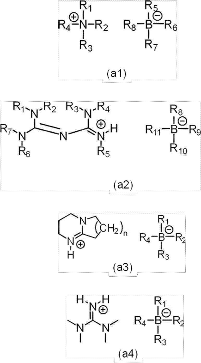
式(a2)中、R1~R7は、それぞれ独立に、炭素数1~8のアルキル基又は炭素数3~8のシクロアルキル基を表し、R8~R11は、それぞれ独立に、炭素数1~8のアルキル基、フェニル基、ナフチル基、アントラセニル基又はフェナンスリル基を表し、前記フェニル基、前記ナフチル基、前記アントラセニル基及び前記フェナンスリル基は、ハロゲン原子、アルキル基、アリール基、アルケニル基、シクロアルキル基又は複素環基によって置換されていてもよい。
式(a3)中、nは、1~3の整数を表し、R1~R4は、それぞれ独立に、炭素数1~8のアルキル基、フェニル基、ナフチル基、アントラセニル基又はフェナンスリル基を表し、前記フェニル基、前記ナフチル基、前記アントラセニル基及び前記フェナンスリル基は、ハロゲン原子、アルキル基、アリール基、アルケニル基、シクロアルキル基又は複素環基によって置換されていてもよい。
式(a4)中、R1~R4は、それぞれ独立に、炭素数1~8のアルキル基、フェニル基、ナフチル基、アントラセニル基又はフェナンスリル基を表し、前記フェニル基、前記ナフチル基、前記アントラセニル基及び前記フェナンスリル基は、ハロゲン原子、アルキル基、アリール基、アルケニル基、シクロアルキル基又は複素環基によって置換されていてもよい。
<4B> 前記ポリイソ(チオ)シアネート化合物(b)は、ペンタメチレンジイソシアネート、ヘキサメチレンジイソシアネート、キシリレンジイソシアネート、イソホロンジイソシアネート、ビス(イソシアナトメチル)シクロヘキサン、ビス(イソシアナトシクロヘキシル)メタン、2,5-ビス(イソシアナトメチル)ビシクロ-[2.2.1]-ヘプタン、2,6-ビス(イソシアナトメチル)ビシクロ-[2.2.1]-ヘプタン、トリレンジイソシアネート、4,4’-ジフェニルメタンジイソシアネート、及びフェニレンジイソシアネートからなる群から選択される少なくとも1つを含む<1B>~<3B>のいずれか1つに記載の光硬化性組成物。
<5B> 前記ポリチオール化合物(c)は、5,7-ジメルカプトメチル-1,11-ジメルカプト-3,6,9-トリチアウンデカン、4,7-ジメルカプトメチル-1,11-ジメルカプト-3,6,9-トリチアウンデカン、4,8-ジメルカプトメチル-1,11-ジメルカプト-3,6,9-トリチアウンデカン、4-メルカプトメチル-1,8-ジメルカプト-3,6-ジチアオクタン、ペンタエリスリトールテトラキス(3-メルカプトプロピオネート)、ペンタエリスリトールテトラキス(2-メルカプトアセテート)、2,5-ビス(メルカプトメチル)-1,4-ジチアン、ビス(2-メルカプトエチル)スルフィド、1,1,3,3-テトラキス(メルカプトメチルチオ)プロパン、4,6-ビス(メルカプトメチルチオ)-1,3-ジチアン、2-(2,2-ビス(メルカプトメチルチオ)エチル)-1,3-ジチエタン、1,1,2,2-テトラキス(メルカプトメチルチオ)エタン、3-メルカプトメチル-1,5-ジメルカプト-2,4-ジチアペンタン、及びトリス(メルカプトメチルチオ)メタンからなる群から選択される少なくとも1つを含む<1B>~<4B>のいずれか1つに記載の光硬化性組成物。
<6B> さらに、金属触媒を含む<1B>~<5B>のいずれか1つに記載の光硬化性組成物。
<7B> <1B>~<6B>のいずれか1つに記載の光硬化性組成物の硬化物を含む光学部材。
<8B> <1B>~<6B>のいずれか1つに記載の光硬化性組成物の硬化物である硬化層を含む積層体。
<9B> 樹脂基材と、前記樹脂基材上に配置される<1B>~<6B>のいずれか1つに記載の光硬化性組成物の硬化物である硬化層と、を含む積層体。
<10B> 前記樹脂基材がチオウレタン樹脂又はエピスルフィド樹脂を含む<9B>に記載の積層体。
<11B> 前記硬化層が、前記樹脂基材と接する面とは反対の面に、フレネルレンズパターンを有する<9B>又は<10B>に記載の積層体。
<12B> 前記硬化層が、前記樹脂基材と接する面とは反対の面に、マイクロレンズパターンを有する<9B>又は<10B>に記載の積層体。
<13B> <1B>~<6B>のいずれか1つに記載の光硬化性組成物を、紫外線又は可視光の照射により硬化させて硬化物を得る工程を含む硬化物の製造方法。
<14B> <1B>~<6B>のいずれか1つに記載の光硬化性組成物を樹脂基材の表面に付与する工程と、樹脂基材の表面に付与された前記光硬化性組成物を、紫外線又は可視光の照射により硬化させて硬化層を得る工程と、を含む積層体の製造方法。
<15B> <1B>~<6B>のいずれか1つに記載の光硬化性組成物を、成形型及び樹脂基材のいずれか一方の表面に付与し、前記いずれか一方の表面に付与された前記光硬化性組成物の表面に他方を載置することにより、前記成形型と前記樹脂基材との間に前記光硬化性組成物を介在させる工程(a)と、前記工程(a)の後、前記成形型と前記樹脂基材との間に介在する前記光硬化性組成物を、紫外線又は可視光の照射により硬化させて硬化層を得る工程(b)と、を含む積層体の製造方法。
<16B> 前記工程(a)が、前記光硬化性組成物を前記成形型の表面に付与し、前記成形型の表面に付与された前記光硬化性組成物の表面に前記樹脂基材を載置することにより、前記成形型と前記樹脂基材との間に前記光硬化性組成物を介在させる工程であり、前記工程(b)の後に、前記硬化層及び前記樹脂基材と成形型とを分離する工程(c)をさらに含む<15B>に記載の積層体の製造方法。
<17B> 前記成形型が、フレネルレンズパターンを有し、前記工程(a)において、前記光硬化性組成物を前記成形型のフレネルレンズパターンを有する面に付与する<15B>又は<16B>に記載の積層体の製造方法。
<18B> 前記成形型が、マイクロレンズパターンを有し、前記工程(a)において、前記光硬化性組成物を前記成形型のマイクロレンズパターンを有する面に付与する<15B>又は<16B>に記載の積層体の製造方法。
各実施例及び比較例について、得られた光硬化性組成物における各成分(光塩基発生剤、光増感剤の溶解性等)の溶解性を、以下の方法で評価した。
溶解性は、硬化性組成物を混合した後に、硬化性組成物の中に固体物質が残存しているかを目視にて評価した。目視にて固体物質が残存していないと認められた場合をAと評価し、固体物質が残存していると認められた場合をBと評価した。硬化性組成物の混合方法については、実施例中に記載した。
各実施例及び比較例について、得られた硬化物の硬化状態を、以下の方法で評価した。
硬化性組成物の硬化状態は、硬化を実施した後に、硬化性組成物の流動性が無くなっているかを目視にて評価した。目視にて流動性が無くなっていると認められた場合をAと評価し、流動性が無くなっていないと認められた場合をBと評価した。硬化性組成物の硬化方法については、実施例中に記載した。
各実施例及び比較例について、パートBで得られた硬化物の密着性を、以下の方法で評価した。
ニチバン株式会社製セロテープ(登録商標)CT405AP-18を用いた剥離試験により、JIS K5400-8.5:1999に準拠して硬化物の密着性を評価した。切り込みの間隔は、1mmとし、切り込みにより100個のマス目を作製した。
評価結果は、サンプル中の硬化物の表面積に対する剥離されなかった部分の面積の割合を表す。
例えば、評価結果が100%であることは、サンプル中の硬化物の表面積に対する剥離されなかった部分の面積の割合が100%であることを意味する。即ち全く剥離されなかったことを意味する。マス目の一部が剥離していると認められた場合、そのマス目は、剥離したものと見做した。
日本セミラボ株式会社製の分光エリプソメーターSE-2000を用いて、室温にて測定した。屈折率の値は、546nmの波長の光の屈折率とした。
硬化物の膜厚は、株式会社ミツトヨ製のデジマチックインジケータID-H及びコンパレータスタンドBSB-20Xを用いて測定した。硬化物と基材を合わせた厚さから、基材の厚さを除した値を、硬化物の膜厚とした。
蛍光灯で照らされた室内にて、硬化体に白濁が生じているか目視にて確認した。
アイグラフィックス株式会社製のUV照射用電源UB012-0BM-60Hz用を有し、箱型の筐体内に、アイグラフィックス株式会社製のメタルハライドランプM01-L212(アーク長122mm、ランプ出力80W/cm)を有するバッチ式のUV硬化装置を使用した。本UV硬化装置は指定の時間のみ、サンプルに紫外線を照射できるようになっており、サンプルに照射するUV光の積算光量を変更できる。また、ランプの出力は750W、1,000Wの2段階で切り替えられ、サンプルとメタルハライドランプとの距離は可変であり、UV光の照射強度を変更できる。
UVA(320nm~390nm)の波長範囲の紫外線強度は、EIT(登録商標),INC.社製のUVAシングルバンド光量計UVICURE(登録商標) Plus IIを使用して、測定した。光量計の校正はEIT(登録商標),INC.社によって行われた。
UVC(250nm~260nm)の波長範囲の紫外線強度は、EIT,INC.社製のUVCシングルバンド光量計UVICURE Plus IIを使用して、測定した。
光量計の校正はEIT,INC.社によって行われた。
C-1、C-2及びD-1のナトリウムD線(波長589.3nmの光)の屈折率は、株式会社アタゴ製のアッベ屈折計NAR-4Tを用いて測定した。測定温度は、20℃とした。
上記の測定方法により得られたC-1、C-2及びD-1の屈折率は以下の通りである。
C-1: 1.648
C-2: 1.631
D-1: 1.65
ジアザビシクロウンデセン(10mmol、1,8-ジアザビシクロ[5.4.0]ウンデカ-7-エン、東京化成工業(株)製)を10質量%の塩酸(10mL)に溶解させた。この溶液を撹拌しながら、この溶液に対して、テトラフェニルホウ酸ナトリウム(10.5mmol、東京化成工業(株)製)を滴下した。生成した沈殿物をろ別し、水により洗浄した後、さらにメタノールにより洗浄した。洗浄後の沈殿物をアセトンとメタノールの混合液により再結晶した後、減圧下で乾燥し、A-6(1.47g)を得た。得られたA-6の同定データを以下に示す。
1H-NMR(DMSO-d6)、δ(ppm):1.56~1.70(m、6H)、1.9(q、2H)、2.62(t、2H)、3.23(t、2H)、3.45(t、2H)、3.57(2H)、6.79(t、4H)、7.18、(m、8H)、9.47(NH、1H)
合成例1Aにおいて、ジアザビシクロウンデセンの代わりにジアザビシクロノネン(10mmol、1,5-ジアザビシクロ[4.3.0]-5-ノネン、東京化成工業(株)製)を使用した以外は、同様の手順によりA-7(2.12g)を得た。得られたA-7の同定データを以下に示す。
1H-NMR(DMSO-d6)、δ(ppm):1.87(q、2H)、1.99(
q、2H)、2.77(t、2H)、3.26(t、2H)、3.32(t、5H)、3.56(t、2H)、6.79(t、4H)、6.92(t、8H)、7.18(m、8H)、9.57(NH、1H)
合成例1Aにおいて、ジアザビシクロウンデセンの代わりに1,1,3,3-テトラメチルグアニジン(10mmol、東京化成工業(株)製)を使用した以外は、同様の手順によりA-8(1.91g)を得た。得られたA-8の同定データを以下に示す。
1H-NMR(DMSO-d6)、δ(ppm):2.86(s、12H)、6.79(t、4H)、6.92(t、8H)、7.18(m、8H)、7.75(NH、2H)
(パートA:光硬化性組成物の調製)
表1に記載した種類及び質量部で、塩基発生剤、ポリイソシアネート化合物及び、必要に応じて、光増感剤、金属触媒をガラス製のバイアルに秤量した。バイアルに、撹拌子を入れてマグネチックスターラーを用いて100rpm(revolutions per
minute)~500rpmの回転速度で撹拌混合した。混合の際は、バイアルの蓋を閉めて外気との接触を防いだ。混合は、25℃で、1時間~6時間実施した。
この溶液に、表1に記載した種類及び質量部で、ポリチオール化合物、必要に応じて、ポリエピスルフィド化合物を加え、100rpm~500rpmの回転速度で撹拌混合して光硬化性組成物を調製した。混合は、25℃で、1時間~6時間実施した。溶解性の評価結果を、表2に記した。混合した光硬化性組成物に、400Pa以下の減圧下にて30分~1時間脱泡を行った後、孔径が1μmのポリテトラフルオロエチレン製メンブレンフィルターでろ過を行った。
アズワン株式会社製の超音波洗浄器MCS-6に、10質量%の水酸化カリウム水溶液を装入した。超音波洗浄器の発信周波数は、40kHzであり、超音波の出力は、150Wであった。
この溶液にガラス板(ソーダガラス製、厚さ2mm、1辺70mmの正方形板)を浸漬して、50℃~55℃で5分間超音波を照射した。超音波照射後、ガラス板を取り出して流水で3分間洗浄し、続いてこのガラス板を、イオン交換水を装入した超音波発生装置を備えた容器中に浸漬して、45℃で5分間超音波を照射した。超音波照射後、ガラス板を取り出して、110℃に設定した強制送風循環式の恒温オーブン内で約30分間加熱した。加熱が終了したら、ガラス板をオーブンから取り出し、18~30℃の室温で30分以上ガラス板を冷却した。
ポリテトラフルオロエチレン製の板(各辺70mmの正方形板)の上に、パートAで調製した光硬化性組成物を、スポイトを使って1滴又は2滴、滴下した。事前に、ポリテトラフルオロエチレン製の板の上には、プラスチック製の粘着テープ(幅10mm、長さ60mm)を各辺に沿って貼り付けて、光硬化性組成物がポリテトラフルオロエチレン製の板からこぼれることを防いだ。光硬化性組成物の温度は、20℃~30℃の室温と同じ温度とした。ポリテトラフルオロエチレン製の板における光硬化性組成物を滴下した面に、エッチング処理した上述のガラス板を乗せて、ポリテトラフルオロエチレン製の板及びガラス板により光硬化性組成物を挟んだ。その後、光硬化性組成物を硬化して硬化物を作製した。
光硬化性組成物の硬化は、以下に説明する「UV照射のみ」又は「UV照射及び加熱」によって実施した。それぞれの実施例の硬化条件及び硬化状態の評価結果については、表2に記した。
UV(ultraviolet)硬化装置を使って、ポリテトラフルオロエチレン製の板及びガラス板により挟んだ光硬化性組成物にUV光を照射した。UV光は、ガラス板の面から照射した。UVの照射は、相対湿度が30%~70%、気温が18℃~30℃の大気の雰囲気下で行った。照射したUV光の強度は、UVAの波長領域のUV光の照射強度が255mW/cm2、UVCの波長領域のUV光の照射強度が75mW/cm2であった。
UV光の照射が終了した後、UV硬化装置からポリテトラフルオロエチレン製の板及びガラス板で挟まれた硬化物を取り出した。得られた硬化物から、ポリテトラフルオロエチレン製の板を取り外した。
UV硬化装置を使って、ポリテトラフルオロエチレン製の板及びガラス板により挟んだ光硬化性組成物にUV光を照射した。UV光は、ガラス板の面から照射した。UVの照射は、相対湿度が30%~70%、気温が18℃~30℃の大気の雰囲気下で行った。照射したUV光の強度は、UVAの波長領域のUV光の照射強度が255mW/cm2、UVCの波長領域のUV光の照射強度が75mW/cm2であった。
UV光の照射が終了した後、ポリテトラフルオロエチレン製の板及びガラス板で挟まれた硬化物をUV硬化装置から取り出し、強制送風循環式の恒温電気炉内で加熱した。加熱が終了した後、ポリテトラフルオロエチレン製の板及びガラス板で挟まれた硬化物を電気炉から取り出し、室温まで冷却した。得られた硬化物から、ポリテトラフルオロエチレン製の板を取り外した。

(塩基発生剤)
A-1:1,2-ジシクロヘキシル-4,4,5,5-テトラメチルビグアニジウム=n-ブチルトリフェニルボラート(富士フィルム和光純薬株式会社製、WPBG-300)[式(2)で表される化合物]
A-2:1,2-ジシクロヘキシル-4,4,5,5-テトラメチルビグアニジウム=テトラキス(3-フルオロフェニル)ボラート(富士フィルム和光純薬株式会社製、WPBG-345)[式(2)で表される化合物]
A-3:テトラ(n-ブチル)アンモニウム=n-ブチルトリフェニルボラート(昭和電工株式会社製、P3B)[式(1)で表される化合物]
A-4:テトラ(n-ブチル)アンモニウム=n-ブチルトリ(1-ナフチル)ボラート(昭和電工株式会社製、N3B)[式(1)で表される化合物]
A-5:9-アントリルメチル-N,N-ジエチルカーバメート(富士フィルム和光純薬株式会社製、WPBG-018)[式(1)~式(4)のいずれにも該当しない化合物]A-6:合成例1Aに従って製造した以下の構造を有する塩基発生剤[式(3)で表される化合物]


B-1:2,5-ビス(イソシアナトメチル)ビシクロ-[2.2.1]-ヘプタン、及び2,6-ビス(イソシアナトメチル)ビシクロ-[2.2.1]-ヘプタン
B-2:キシリレンジイソシアネート
(ポリチオール化合物)
C-1:5,7-ジメルカプトメチル-1,11-ジメルカプト-3,6,9-トリチアウンデカン、4,7-ジメルカプトメチル-1,11-ジメルカプト-3,6,9-トリチアウンデカン、及び4,8-ジメルカプトメチル-1,11-ジメルカプト-3,6,9-トリチアウンデカンの混合物
C-2:4-メルカプトメチル-1,8-ジメルカプト-3,6-ジチアオクタン
(ポリエピスルフィド化合物)
D-1:ビス(2,3-エピチオプロピル)ジスルフィド
(光増感剤)
E-1:9,10-ジブトキシアントラセン(川崎化成工業株式会社製、UVS-1331)
E-2:4-ベンゾイル-4’-メチルジフェニルスルフィド(東京化成工業株式会社製)
E-3:2-エチルアントラキノン(富士フィルム和光純薬株式会社製)
(金属触媒)
F-1:ジメチルスズ(IV)ジクロライド

UV照射及び加熱の硬化方法を用いた実施例4Aは、UV照射のみの硬化方法を用いた実施例3Aと比較して、密着性により優れている。即ち、UV照射及び加熱の硬化方法を用いる場合は、UV照射のみの硬化方法を用いる場合より、密着性により優れることがわかった。
ポリイソ(チオ)シアネート化合物(b)とポリチオール化合物(c)とを合計で100質量部用いた実施例2Aは、ポリイソ(チオ)シアネート化合物(b)とポリチオール化合物(c)とを合計で80質量部用いた実施例8Aと比較して、密着性により優れていた。
(パートC:光硬化性組成物の調製)
比較例1A~比較例3Aについては、以下の方法で光硬化性組成物を調製した。
表3に記載の種類及び質量部で、塩基発生剤、ポリエピスルフィド化合物及び、必要に応じて、増感剤をガラス製のバイアルに秤量した。バイアルに、撹拌子を入れてマグネチックスターラーを用いて100rpm~500rpmの回転速度で撹拌混合して光硬化性組成物を調製した。混合の際は、バイアルの蓋を閉めて外気との接触を防いだ。混合は、25℃で、1時間~6時間実施した。混合した光硬化性組成物を、400Pa以下の減圧下にて30分~1時間脱泡を行った後、孔径が1μmのポリテトラフルオロエチレン製メンブレンフィルターでろ過を行った。
得られた光硬化性組成物を用いて、パートBと同様の方法で、光硬化性組成物を硬化して硬化物を作製した。それぞれの比較例の硬化条件及び硬化状態の評価結果については、表4に記載した。硬化性組成物の流動性が無くなっていた場合は、密着性を評価した。密着性の評価結果は、表4に記した。

表3中の略号の詳細は、上述の表1中の略号の詳細と同様である。

ポリイソ(チオ)シアネート化合物(b)と、ポリチオール化合物(c)と、を含まない光硬化性組成物を用いた比較例2A及び比較例3Aは、チオウレタン樹脂を形成しなかった。また、比較例2A及び比較例3Aは密着性に劣っていた。
塩基発生剤として式(1)~式(4)で表される化合物からなる群から選択される少なくとも1つを含まない光硬化性組成物を用いた比較例4Aは、硬化状態に劣っており、硬化させることができなかった。
[実施例16A]
49.8質量部のポリイソシアネート化合物B-2と0.2質量部の塩基発生剤A-4、0.01質量部の金属触媒F-1をガラスバイアル中に秤量した。ガラスバイアルに、撹拌子を入れてマグネチックスターラーを用いて100rpm~500rpmの回転速度で撹拌混合した。混合の際は、バイアルの蓋を閉めて外気との接触を防いだ。混合は、25℃で、1時間~6時間実施した。
この溶液に、50.2質量部のポリチオール化合物C-1を加え、100rpm~500rpmの回転速度で撹拌混合して光硬化性組成物を調製した。混合は、25℃で、1時間~6時間実施した。混合した光硬化性組成物を、400Pa以下の減圧下にて30分~1時間脱泡を行った後、孔径が1μmのポリテトラフルオロエチレン製メンブレンフィルターでろ過を行った。
UV照射後に、ガラス板に挟まれた硬化物をさらに、電気炉中、120℃で60分間加熱した。硬化物からガラス板を取り外し、直径70mm、厚さ2mmの円板状の硬化物を得た。得られた硬化物を、さらに電気炉中、120℃で60分間加熱アニールした。アニール後の硬化物を、幅3mm、奥行き3mm、高さ2mmの大きさに切り出し、硬化物のガラス転移温度(Tg)を測定した。硬化物のTgは、95℃であった。
Tgの測定は、TMAペネトレーション法(50g荷重、ピン先0.5mmφ、昇温速
度10℃/min、加熱温度範囲は室温~140℃、サンプルの大きさは4mm×4mm×2mmに加工)により、島津製作所社製の熱機械分析装置TMA-60を用いて測定した。
なお、上述と同様の方法で、金属触媒F-1を添加していない光硬化性組成物を調製し、硬化物を作製し、上記硬化物のTgを測定したところ、88℃であった。
また、得られたこれらの硬化物の屈折率は、1.67であり、透明性を有しており、光学部材、光導波路等として適していた。
[実施例17A]
54.3質量部のポリイソシアネート化合物B-1と1質量部の塩基発生剤A-3、光増感剤として、0.5質量部の9,10-ビス(オクタノイルオキシ)アントラセン(川崎化成工業株式会社製、UVS-581)をガラスバイアル中に秤量した。ガラスバイアルに、撹拌子を入れてマグネチックスターラーを用いて100rpm~500rpmの回転速度で撹拌混合した。混合の際は、バイアルの蓋を閉めて外気との接触を防いだ。混合は、25℃で、1時間~6時間実施した。
この溶液に、45.7質量部のポリチオール化合物C-2を加え、100rpm~500rpmの回転速度で撹拌混合して光硬化性組成物を調製した。混合は、25℃で、1時間~6時間実施した。混合した光硬化性組成物を、400Pa以下の減圧下にて30分~1時間脱泡を行った後、孔径が1μmのポリテトラフルオロエチレン製メンブレンフィルターでろ過を行った。
UV照射後に、硬化物からモールドを取り外し、モールドのパターンが硬化物にインプリントされたインプリント部材を得た。インプリント部材の表面を、電子顕微鏡により観察することにより、モールドの表面構造が硬化物にインプリントされていることが観察された。
なお、本実施例で用いたモールド表面には、100nmの高さ、100nmの半径の直円錐が繰り返し形成された構造を有していた。また、モールドが硬化物から剥離しやすくするために、モールド表面には、予めフッ素系の外部離型剤を表面に塗布しておいた。
[実施例18A]
実施例1AのパートBに記載の、アルカリ洗浄したガラス板及びポリテトラフルオロエチレン製の板を、2枚のフッ素系離型剤を塗布したガラス板に変更して光硬化性組成物を挟んだこと以外は、実施例1Aと同様の手順で硬化した。硬化物をガラス板から剥離することにより、フィルム状の硬化物を得た。フィルムの厚さは、130μm~170μmであり、フィルムの屈折率は、1.67であった。フィルムは、透明性を有しており、光学部材として適していた。
フィルム端部から光を入射させて、光を入射させた端部の反対側の端部を観察すると、入射した光が出射していることが認められた。第1実施形態の硬化物は、光導波路として機能した。
[実施例19A]
実施例16Aに記載のフッ素系の外部離型剤を塗布した直径70mmのソーダガラス円板2枚を、フッ素系の外部離型剤を塗布したカーブ形状を有する直径81mmのガラスモールドに変更し、ガラスモールドとテープからなるキャビティ(カーブ形状:凹凸面共に4カーブ、中心厚:2mm)を作製したこと以外は、実施例16Aと同様の手順で硬化物を得た。硬化物は凹凸面共に4カーブ、2mmの中心厚、直径81mmのレンズ形状を有しており、金属触媒F-1の有無に関わらず透明性を有しており、レンズとして好適であった。
[実施例20A]
100mLの容量のサンプル瓶に、内部離型剤としてZELEC(登録商標)UN(Stepan社製)を0.02質量部(1,000ppm)、UV吸収剤として2-(2’
-ヒドロキシ-5’-t-オクチルフェニル)ベンゾトリアゾール(共同薬品(株)製、
商品名バイオソーブ583)を0.3質量部(15,000ppm)、触媒としてジブチル錫(II)ジクロリドを0.01質量部(500ppm)、重合性化合物として2,5(6)-ビス(イソシアナトメチル)ビシクロ-[2.2.1]-ヘプタンを10.12質量部、添加して20℃で撹拌混合し均一溶液を得た。
この均一溶液に、さらに重合性化合物としてペンタエリスリトールテトラキス(3-メルカプトプロピオネート)を4.78質量部、4-メルカプトメチル-1,8-ジメルカプト-3,6-ジチアオクタンを 5.1質量部、加えて20℃にて撹拌混合し、均一な重合性組成物を得た。
重合性組成物を入れたガラスモールドとテープからなるキャビティを重合オーブンに入れ、25℃から120℃まで19時間かけて徐々に昇温した後120℃で2時間保持して重合した。冷却後、ガラスモールドとテープを剥離して、内部に形成された硬化樹脂からなる成形体(プラスチックレンズ)を取り出した。得られた成形体(プラスチックレンズ)は無色透明で屈折率ne1.60、アッベ数νe40であった。
%~70%、気温が18℃~30℃の大気の雰囲気下で行った。照射したUV光の強度は、UVAの波長領域のUV光の照射強度が255mW/cm2、UVCの波長領域のUV光の照射強度が75mW/cm2であった。UV光の照射が終了した後、硬化物が製膜されたプラスチックレンズをUV硬化装置から取り出し、強制送風循環式の恒温電気炉内で、110℃、30分間加熱した。加熱が終了した後、プラスチックレンズを室温まで冷却し、表面に硬化物のコーティングが製膜された積層構造を有するレンズを得た。
コーティングが製膜された積層構造を有するレンズを用いて、コーティングの密着性を評価したところ、コーティングの剥がれは認められなかった。
[実施例21A]
100mLの容量のサンプル瓶に、内部離型剤としてStepan社製 ZELEC UNを0.02質量部(1,000ppm)、UV吸収剤として2-(2’-ヒドロキシ
-5’-t-オクチルフェニル)ベンゾトリアゾール(共同薬品社製 商品名バイオソー
ブ583)を0.3質量部(15,000ppm)、触媒としてジブチル錫(II)ジクロリドを0.01質量部(500ppm)、重合性化合物としてm-キシリレンジイソシアネートを10.12質量部、添加して20℃で撹拌混合し均一溶液を得た。この均一溶液に、さらに重合性化合物として5,7-ジメルカプトメチル-1,11-ジメルカプト-3,6,9-トリチアウンデカン、4,7-ジメルカプトメチル-1,11-ジメルカプト-3,6,9-トリチアウンデカン、4,8-ジメルカプトメチル-1,11-ジメルカプト-3,6,9-トリチアウンデカンの混合物を9.88質量部、添加して20℃にて撹拌混合し、均一な重合性性組成物を得た。この重合性組成物を400Pa以下の減圧下にて30分~1時間脱泡を行った後、孔径が1μmのポリテトラフルオロエチレン製メンブレンフィルターでろ過を行い、ガラスモールドとテープからなるキャビティ(カーブ形状:凹凸面共に4カーブ、中心厚:2mm)に注入しテープで密封した。重合性組成物を入れたガラスモールドとテープからなるキャビティを重合オーブンに入れ、25℃から120℃まで19時間かけて徐々に昇温した後120℃で2時間保持して重合した。冷却後、ガラスモールドとテープを剥離して、内部に形成された硬化樹脂からなる成形体(プラスチックレンズ)を取り出した。得られたプラスチックレンズは無色透明で屈折率ne1.67、アッベ数νe31、光学屈折力0ジオプトリーであった。
ズ及びガラスモールドが完全に接し、光硬化性組成物の層の厚みが失われないようにした。得られたプラスチックレンズ、光硬化性組成物及びガラスモールドの積層体に対して、UV硬化装置を使ってUV光を照射した。UV光は、ガラスモールドの面の方向から、20秒間照射した。UVの照射は、相対湿度が30%~70%、気温が18℃~30℃の大気の雰囲気下で行った。照射したUV光の強度は、UVAの波長領域のUV光の照射強度が255mW/cm2、UVCの波長領域のUV光の照射強度が75mW/cm2であった。
[実施例22A]
100mLの容量のサンプル瓶に、内部離型剤としてStepan社製 ZELEC UNを0.02質量部(1,000ppm)、UV吸収剤として2-(2’-ヒドロキシ
-5’-t-オクチルフェニル)ベンゾトリアゾール(共同薬品社製 商品名バイオソー
ブ583)を0.3質量部(15,000ppm)、触媒としてジブチル錫(II)ジクロリドを0.01質量部(500ppm)、重合性化合物としてm-キシリレンジイソシアネートを10.12質量部、添加して20℃で撹拌混合し均一溶液を得た。この均一溶液に、さらに重合性化合物として5,7-ジメルカプトメチル-1,11-ジメルカプト-3,6,9-トリチアウンデカン、4,7-ジメルカプトメチル-1,11-ジメルカプト-3,6,9-トリチアウンデカン、4,8-ジメルカプトメチル-1,11-ジメルカプト-3,6,9-トリチアウンデカンの混合物を9.88質量部、添加して20℃にて撹拌混合し、均一な重合性組成物を得た。この重合性組成物を400Pa以下の減圧下にて30分~1時間脱泡を行った後、孔径が1μmのポリテトラフルオロエチレン製メンブレンフィルターでろ過を行い、ガラスモールドとテープからなるキャビティ(カーブ形状:凹凸面共に4カーブ、中心厚:2mm)に注入しテープで密封した。重合性組成物を入れたガラスモールドとテープからなるキャビティを重合オーブンに入れ、25℃から120℃まで19時間かけて徐々に昇温した後120℃で2時間保持して重合した。冷却後、ガラスモールドとテープを剥離して、内部に形成された硬化樹脂からなる成形体(プラスチックレンズ)を取り出した。得られたプラスチックレンズは無色透明で屈折率ne1.67、アッベ数νe31であった。
冷却後のプラスチックレンズの凸面に、実施例1Aの組成を用いてパートAに記載した方法により調製した光硬化性組成物を、マイクロピペットを用いて滴下した。UV硬化装置を使って、滴下された光硬化性組成物にUV光を照射した。UV光は、プラスチックレンズの凸面の方向から、20秒間照射した。UVの照射は、相対湿度が30%~70%、気
温が18℃~30℃の大気の雰囲気下で行った。照射したUV光の強度は、UVAの波長領域のUV光の照射強度が255mW/cm2、UVCの波長領域のUV光の照射強度が75mW/cm2であった。
以下の実施例及び比較例において行った評価は、以下の通りである。
各実施例及び比較例について、光硬化性を、以下の方法で評価した。
光硬化性は、UV硬化装置(アイグラフィックス株式会社製、UB012-0BM-60Hz)を用いて光硬化性組成物にUV照射を行った後に、光硬化性組成物の硬化性を以下の基準で評価した。
[評価基準]
A:光硬化性組成物が重合により固まり硬化物が得られた。
B:光硬化性組成物が固まらず硬化物が得られなかった。
各実施例及び比較例について、透明性を、以下の方法で評価した。
蛍光灯で照らされた室内で目視により硬化物を確認し、以下の基準で評価した。
[評価基準]
A:硬化物が透明であり白濁がなかった。
B:硬化物が透明でなかった、又は白濁があった。
各実施例及び比較例について、離型性を、以下の方法で評価した。
重合後の硬化物をモールドから取り外す際に、硬化物の離型性を以下の基準で評価した。
A:硬化物に損傷を与えることなく、大きな力を加えることなく、取り外すことができた。
B:取り外すことはできたが硬化物に損傷が確認された、大きな力を加えなければ取り外すことができなかった、又は取り外すことができなかった。
まず、テトラブチルアンモニウムトリ(1-ナフチル)ブチルボレート(0.04質量部、塩基発生剤、式(a1)に該当、昭和電工株式会社製)をポリイソシアネート化合物であるキシリレンジイソシアネート(19.9質量部)に溶解した。完全に溶解した後、ポリチオール化合物である5,7-ジメルカプトメチル-1,11-ジメルカプト-3,6,9-トリチアウンデカン、4,7-ジメルカプトメチル-1,11-ジメルカプト-3,6,9-トリチアウンデカン、および4,8-ジメルカプトメチル-1,11-ジメルカプト-3,6,9-トリチアウンデカンを主成分とするポリチオール組成物(20.1質量部)を加え、さらに30分間撹拌して光硬化性組成物を調製した。
得られた光硬化性組成物を3μmPTFEフィルターでろ過し、30分~60分間撹拌しながら真空下で脱気した。調製された光硬化性組成物を、厚さ1.1mmのガラスモールドに移した。90秒間(9.5mW/cm2/s at 365nm)の光照射を行った後、オーブン内で、120℃で1時間加熱することにより、光硬化性組成物の重合硬化を行った。
ガラスモールドから重合硬化後の硬化物を離型することを試みたが失敗した。
テトラブチルアンモニウムトリ(1-ナフチル)ブチルボレート(0.04質量部、昭和電工株式会社製)とSH-3773M(0.02質量部、内部離型剤、ダウ・ケミカル日本株式会社製)をポリイソシアネート化合物であるキシリレンジイソシアネート(19.9質量部)に溶解した。完全に溶解した後、ポリチオール化合物である5,7-ジメルカプトメチル-1,11-ジメルカプト-3,6,9-トリチアンデカン、4,7-ジメルカプトメチル-1,11-ジメルカプト-3,6,9-トリチアンデカン、および4,8-ジメルカプトメチル-1,11-ジメルカプト-3,6,9-トリチアウンデカンを主成分とするポリチオール組成物(20.1質量部)を加え、さらに30分間撹拌して光硬化性組成物を調製した。
得られた光硬化性組成物を3μmPTFEフィルターでろ過し、30分~60分間撹拌しながら真空下で脱気した。
調製された光硬化性組成物を、厚さ1.1mmのガラスモールドに移した。90秒間(9.5mW/cm2/s at 365nm)の光照射を行った後、オーブン内で、120℃で1時間加熱することにより、光硬化性組成物の重合硬化を行った。
重合硬化後の硬化物は、ガラスモールドから自然に離型することができた。また、この硬化物から、透明性に優れた光学部材が得られた。

SH-3773M ポリエーテル変性シリコーン化合物、式(1)と式(2)との混合物に該当
一方、ポリエーテル変性シリコーン化合物(d)を含まない比較例1Bは離型性に劣っていた。
(樹脂Aを含む硬化物の作製)
テトラブチルアンモニウムトリ(1-ナフチル)ブチルボレート(0.2質量部、昭和電工株式会社製)及び表6に示す量の内部離型剤を、ポリイソシアネート化合物であるキシリレンジイソシアネート(50.7質量部)に溶解した。完全に溶解した後、ポリチオール化合物である5,7-ジメルカプトメチル-1,11-ジメルカプト-3,6,9-トリチアンデカン、4,7-ジメルカプトメチル-1,11-ジメルカプト-3,6,9-トリチアンデカン、および4,8-ジメルカプトメチル-1,11-ジメルカプト-3,6,9-トリチアウンデカンを主成分とするポリチオール組成物(49.3質量部)を加え、さらに30分間攪拌して光硬化性組成物を調製した。
得られた光硬化性組成物を3μmPTFEフィルターでろ過し、30分~60分間撹拌しながら真空下で脱気した。調製された光硬化性組成物を、厚さ1.1mmのガラスモールドに移した。90秒間(9.5mW/cm2/s at 365nm)の光照射を行った後、オーブン内で、120℃で1時間加熱することにより、光硬化性組成物の重合硬化を行った。
光硬化性、離型性及び透明性についての結果を表6に示す。
(樹脂Bを含む硬化物の作製)
テトラブチルアンモニウムトリ(1-ナフチル)ブチルボレート(0.2質量部、昭和電工株式会社製)及び表6に示す量の内部離型剤を、ポリイソシアネート化合物である2,5-ビス(イソシアナトメチル)ビシクロ[2.2.1]ヘプタンと2,6-ビス(イソシアナトメチル)ビシクロ[2.2.1]ヘプタンとの混合物(54.3質量部)に溶解した。完全に溶解した後、ポリチオール化合物である4-メルカプトメチル-1,8-ジメルカプト-3,6-ジチアオクタンを主成分とするポリチオール組成物(45.7質量部)を加え、さらに30分間撹拌して光硬化性組成物を調製した。
得られた光硬化性組成物を3μmPTFEフィルターでろ過し、30分~60分間撹拌しながら真空下で脱気した。調製された光硬化性組成物を、厚さ1.1mmのガラスモールドに移した。30秒間(9.5mW/cm2/s at 365nm)の光照射を行った後、オーブン内で、120℃で2時間加熱することにより、光硬化性組成物の重合硬化を行った。
光硬化性、離型性及び透明性についての結果を表6に示す。

表6中、各項目に記載された成分の詳細は以下の通りである。
SH-3773M ポリエーテル変性シリコーン化合物(ダウ・ケミカル日本株式会社製)、式(1)と式(2)との混合物に該当
SH-3749 ポリエーテル変性シリコーン化合物(ダウ・ケミカル日本株式会社製)、式(1)と式(2)との混合物に該当
KF-351A ポリエーテル変性シリコーン化合物(信越化学工業株式会社製)、式(1)に該当
KF-352A ポリエーテル変性シリコーン化合物(信越化学工業株式会社製)、式(1)に該当
KF-615A ポリエーテル変性シリコーン化合物(信越化学工業株式会社製)、式(1)に該当
KF-640 ポリエーテル変性シリコーン化合物(信越化学工業株式会社製)、式(1)に該当

(光硬化性組成物Aの作製)
テトラブチルアンモニウムトリ(1-ナフチル)ブチルボレート(0.3質量部、昭和電工株式会社製)、ジメチルスズジクロライド(0.01質量部、金属触媒)、SH-3773M(0.05質量部、内部離型剤、ダウ・ケミカル日本株式会社製)をポリイソシアネート化合物であるキシリレンジイソシアネート(50.7質量部)に溶解した。完全に溶解した後、ポリチオール化合物である5,7-ジメルカプトメチル-1,11-ジメルカプト-3,6,9-トリチアンデカン、4,7-ジメルカプトメチル-1,11-ジメルカプト-3,6,9-トリチアンデカン、および4,8-ジメルカプトメチル-1,11-ジメルカプト-3,6,9-トリチアウンデカンを主成分とするポリチオール組成物(49.3質量部)を加え、さらに30分間撹拌して光硬化性組成物Aを調製した。
得られた光硬化性組成物Aを3μmPTFEフィルターでろ過し、30分~60分間撹拌しながら真空下で脱気した。
~湾曲したレンズ基材A~
内部離型剤としての「ZELEC UN」(Stepan社製品の酸性リン酸エステル系離型剤)0.1質量部と、紫外線吸収剤としての「Viosorb583」(共同薬品株式会社製)0.05質量部とを、ポリイソシアネート化合物であるキシリレンジイソシアネート40.7質量部に溶解した。
得られた溶液に対し、ポリチオール化合物である5,7-ジメルカプトメチル-1,11-ジメルカプト-3,6,9-トリチアンデカン、4,7-ジメルカプトメチル-1,11-ジメルカプト-3,6,9-トリチアンデカン、および4,8-ジメルカプトメチル-1,11-ジメルカプト-3,6,9-トリチアウンデカンを主成分とするポリチオール組成物49.3質量部、を加えて混合液を調製した。
重合触媒である二塩化ジメチルスズ(東京化成工業株式会社製)0.008質量部を、ポリイソシアネート化合物であるキシリレンジイソシアネート10.0質量部に溶解した重合溶媒の溶液を、前記混合液に装入して攪拌混合して重合性組成物を調製した。
得られた重合性組成物を3μmPTFEフィルターでろ過し、20℃で30分~60分間撹拌しながら真空下で脱気した。
脱気後の重合性組成物を、テープで固定された一対の湾曲したガラスモールド間に注入した。
次に、重合性組成物が注入された上記一対の湾曲したガラスモールドをオーブンに投入し、オーブン内温度を、室温から120℃まで除々に昇温させた。
続いて、オーブン内を冷却し、冷却後、オーブンから上記一対の湾曲したガラスモールドを取り出し、次いで一対の湾曲したガラスモールドから樹脂成形体を外し、厚さ5mmの湾曲したレンズ基材Aを得た。
内部離型剤としての「ZELEC UN」(Stepan社製品の酸性リン酸エステル系離型剤)0.1質量部を、ポリイソシアネート化合物であるキシリレンジイソシアネート40.7質量部に溶解した。
得られた溶液に対し、ポリチオール化合物である5,7-ジメルカプトメチル-1,11-ジメルカプト-3,6,9-トリチアンデカン、4,7-ジメルカプトメチル-1,11-ジメルカプト-3,6,9-トリチアンデカン、および4,8-ジメルカプトメチル-1,11-ジメルカプト-3,6,9-トリチアウンデカンを主成分とするポリチオール組成物49.3質量部、を加えて混合液を調製した。
重合触媒である二塩化ジメチルスズ(東京化成工業株式会社製)0.008質量部を、ポリイソシアネート化合物であるキシリレンジイソシアネート10.0質量部に溶解した重合溶媒の溶液を、前記混合液に装入して攪拌混合して重合性組成物を調製した。
得られた重合性組成物を3μmPTFEフィルターでろ過し、20℃で30分~60分間撹拌しながら真空下で脱気した。
脱気後の重合性組成物を、テープで固定された一対の平らなガラスモールド間に注入した。
次に、重合性組成物が注入された上記一対の平らなガラスモールドをオーブンに投入し、オーブン内温度を、室温から120℃まで除々に昇温させた。
続いて、オーブン内を冷却し、冷却後、オーブンから上記一対の平らなガラスモールドを取り出し、次いで一対の平らなガラスモールドから樹脂成形体を外し、厚さ2mmの平らなレンズ基材を得た。
湾曲したガラスモールドに、十分な量の光硬化性組成物Aを加えた。次に、上記で得られた湾曲したレンズ基材Aの表面をアルカリ処理又はプラズマ処理によって処理した。
その後、レンズ基材Aを光硬化性組成物Aの上から重ねて、ガラスモールドとレンズ基材Aとの間に光硬化性組成物Aを広く行き渡らせた。
レンズ基材A、光硬化性組成物A及びガラスモールドで形成される積層構造の周囲をテープで固定した。
ガラスモールドとレンズ基材Aとの間の領域は、例えば100μm~300μmの範囲で所望の積層体の厚さを形成し得る。
30秒間(9.5mW/cm2/s at 365nm)の光照射を行った後、オーブン内で、90℃で30分間加熱することにより、光硬化性組成物の重合硬化を行った。
重合硬化後の硬化物及びレンズ基材Aを含む積層体をガラスモールドから取り外し、110℃で1時間アニールした。
重合硬化後の硬化物及びレンズ基材Aを含む積層体は、ガラスモールドから自然に離型することができた。また、この硬化物から、透明性に優れた光学部材が得られた。
フレネルパターンを有する湾曲したガラスモールドに、十分な量の光硬化性組成物Aを加えた。次に、上記で得られた湾曲したレンズ基材Aを光硬化性組成物Aの上から重ねて、ガラスモールドとレンズ基材との間に光硬化性組成物Aを広く行き渡らせた。
レンズ基材A、光硬化性組成物A及びガラスモールドで形成される積層構造の周囲をテープで固定した。
ガラスモールド側から30秒間(9.5mW/cm2/s at 365nm)の光照射を行った後、オーブン内で、90℃で30分間加熱することにより、光硬化性組成物の重合硬化を行った。
重合硬化後の硬化物及びレンズ基材Aを含む積層体をガラスモールドから取り外し、110℃で1時間アニールした。
得られた積層体には、フレネルパターンが転写されていた。
重合硬化後の硬化物及びレンズ基材Aを含む積層体は、ガラスモールドから自然に離型することができた。また、この硬化物から、透明性に優れた光学部材が得られた。
マイクロレンズパターンを有する平らな金型に、十分な量の光硬化性組成物Aを加えた。次に、上記で得られた平らなレンズ基材を光硬化性組成物Aの上から重ねて、金型とレンズ基材との間に光硬化性組成物Aを広く行き渡らせた。
レンズ基材、光硬化性組成物A及び金型で形成される積層構造の周囲をテープで固定した。
レンズ基材側から30秒間(9.5mW/cm2/s at 365nm)の光照射を行った後、オーブン内で、90℃で30分間加熱することにより、光硬化性組成物の重合硬化を行った。
重合硬化後の硬化物及びレンズ基材を含む積層体を金型から取り外し、110℃で1時間アニールした。
得られた積層体には、マイクロレンズパターンが転写されていた。パターン転写性は、レーザー顕微鏡法及び干渉計分光法によって分析した。
重合硬化後の硬化物及びレンズ基材を含む積層体は、ガラスモールドから自然に離型することができた。また、この硬化物から、透明性に優れた光学部材が得られた。
テトラブチルアンモニウムトリ(1-ナフチル)ブチルボレート(0.3質量部、昭和電工株式会社製)、KF-351A(0.1質量部、内部離型剤、信越化学工業株式会社製)をポリイソシアネート化合物である2,5-ビス(イソシアナトメチル)ビシクロ[2.2.1]ヘプタンと2,6-ビス(イソシアナトメチル)ビシクロ[2.2.1]ヘプタンとの混合物(54.3質量部)に溶解した。完全に溶解した後、ポリチオール化合物である4-メルカプトメチル-1,8-ジメルカプト-3,6-ジチアオクタンを主成分とするポリチオール組成物(45.7質量部)を加え、さらに30分間撹拌して光硬化性組成物Aを調製した。
得られた光硬化性組成物Aを3μmPTFEフィルターでろ過し、30分~60分間撹拌しながら真空下で脱気した。
~湾曲したレンズ基材B~
紫外線吸収剤としての「TinuvinPS」(チバガイギー株式会社製)1.1質量部を、ビス(2,3-エピチオプロピル)ジスルフィド100.0質量部に溶解した。
得られた溶液に対し、ポリチオール化合物である5,7-ジメルカプトメチル-1,11-ジメルカプト-3,6,9-トリチアンデカン、4,7-ジメルカプトメチル-1,11-ジメルカプト-3,6,9-トリチアンデカン、および4,8-ジメルカプトメチル-1,11-ジメルカプト-3,6,9-トリチアウンデカンを主成分とするポリチオール組成物9.0質量部、を加えて混合液を調製した。
重合触媒であるN,N-ジシクロヘキシルメチルアミン(東京化成工業株式会社製)0.1質量部、及びN,N-ジメチルシクロヘキシルアミン(東京化成工業株式会社製)0.02質量部を、ポリチオール化合物である5,7-ジメルカプトメチル-1,11-ジメルカプト-3,6,9-トリチアンデカン、4,7-ジメルカプトメチル-1,11-ジメルカプト-3,6,9-トリチアンデカン、および4,8-ジメルカプトメチル-1,11-ジメルカプト-3,6,9-トリチアウンデカンを主成分とするポリチオール組成物1.0質量部に溶解した重合溶媒の溶液を、前記混合液に装入して攪拌混合して重合性組成物を調製した。
得られた重合性組成物を3μmPTFEフィルターでろ過し、20℃で10分間撹拌しながら真空下で脱気した。
脱気後の重合性組成物を、テープで固定された一対の湾曲したガラスモールド間に注入した。
次に、重合性組成物が注入された上記一対の湾曲したガラスモールドをオーブンに投入し、オーブン内温度を、室温から120℃まで除々に昇温させた。
続いて、オーブン内を冷却し、冷却後、オーブンから上記一対の湾曲したガラスモールドを取り出し、次いで一対の湾曲したガラスモールドから樹脂成形体を外し、厚さ5mmの湾曲したレンズ基材Bを得た。
湾曲したガラスモールドに、十分な量の光硬化性組成物Bを加えた。次に、上記で得られた湾曲したレンズ基材Aの表面をアルカリ処理又はプラズマ処理によって処理した。
その後、レンズ基材Aを光硬化性組成物Bの上から重ねて、ガラスモールドとレンズ基材Aとの間に光硬化性組成物Bを広く行き渡らせた。
レンズ基材A、光硬化性組成物B及びガラスモールドで形成される積層構造の周囲をテープで固定した。
ガラスモールドとレンズ基材Aとの間の領域は、例えば100μm~300μmの範囲で所望の積層体の厚さを形成し得る。
60秒間(9.5mW/cm2/s at 365nm)の光照射を行った後、オーブン内で、90℃で30分間加熱することにより、光硬化性組成物の重合硬化を行った。
重合硬化後の硬化物及びレンズ基材Aを含む積層体をガラスモールドから取り外し、120℃で1時間アニールした。
重合硬化後の硬化物及びレンズ基材Aを含む積層体は、ガラスモールドから自然に離型することができた。また、この硬化物から、透明性に優れた光学部材が得られた。
湾曲したガラスモールドに、十分な量の光硬化性組成物Bを加えた。次に、上記で得られた湾曲したレンズ基材Bの表面をアルカリ処理又はプラズマ処理によって処理した。
その後、レンズ基材Bを光硬化性組成物Bの上から重ねて、ガラスモールドとレンズ基材Bとの間に光硬化性組成物Bを広く行き渡らせた。
レンズ基材B、光硬化性組成物B及びガラスモールドで形成される積層構造の周囲をテープで固定した。
ガラスモールドとレンズ基材Bとの間の領域は、例えば100μm~300μmの範囲で所望の積層体の厚さを形成し得る。
60秒間(9.5mW/cm2/s at 365nm)の光照射を行った後、オーブン内で、90℃で30分間加熱することにより、光硬化性組成物の重合硬化を行った。
重合硬化後の硬化物及びレンズ基材Bを含む積層体をガラスモールドから取り外し、120℃で1時間アニールした。
重合硬化後の硬化物及びレンズ基材Bを含む積層体は、ガラスモールドから自然に離型することができた。また、この硬化物から、透明性に優れた光学部材が得られた。
〔光硬化性〕
各実施例及び比較例について、光硬化性を、以下の方法で評価した。
光硬化性は、UV硬化装置(アイグラフィックス株式会社製、UB012-0BM-60Hz)を用いて光硬化性組成物にUV照射を行った後に、光硬化性組成物の硬化性を以下の基準で評価した。
[評価基準]
A:光硬化性組成物が重合により固まり硬化物が得られた。
B:光硬化性組成物が固まらず硬化物が得られなかった。
各実施例及び比較例について、離型性を、以下の方法で評価した。
重合後の硬化物をモールドから取り外す際に、硬化物の離型性を以下の基準で評価した。
A:硬化物に損傷を与えることなく、大きな力を加えることなく、取り外すことができた。
B:取り外すことはできたが硬化物に損傷が確認された、大きな力を加えなければ取り外すことができなかった、又は取り外すことができなかった。
Q-Lab社製加速耐候試験機にて、厚さ0.8mmの樹脂平板を使用して、以下の条件で試験を実施した。
光源:UVA-340、強度:0.5W/m2、試験条件:50℃、150時間
3枚の樹脂平板の試験前後のイエローインデックスの平均変化量に基づいて耐候性を評価した。イエローインデックスの変化量が小さい程、耐光性が良好であると評価した。
分光光度計CM-5(コニカミノルタ製)を使用して、厚さ0.8mm及び2mmの樹脂平板のイエローインデックス(ASTM E313-96)を測定した。
濁度計NDH2000(日本電色工業株式会社製)を使用して、厚さ2mmの樹脂平板のヘイズ値を測定した。
テトラブチルアンモニウムトリ(1-ナフチル)ブチルボレート(0.3質量部、昭和電工株式会社製)、ジメチルスズジクロライド(0.01質量部、金属触媒、東京化成工業株式会社製)、SH-3773M(0.05質量部、内部離型剤、ダウ・ケミカル日本株式会社製)、表8に記載の紫外線吸収剤をポリイソシアネート化合物であるキシリレンジイソシアネート(50.7質量部)に溶解した。
完全に溶解した後、ポリチオール化合物である5,7-ジメルカプトメチル-1,11-ジメルカプト-3,6,9-トリチアンデカン、4,7-ジメルカプトメチル-1,11-ジメルカプト-3,6,9-トリチアンデカン、および4,8-ジメルカプトメチル-1,11-ジメルカプト-3,6,9-トリチアウンデカンを主成分とするポリチオール組成物(49.3質量部)を加え、さらに30分間撹拌して光硬化性組成物を調製した。
得られた光硬化性組成物を3μmPTFEフィルターでろ過し、30分~60分間撹拌しながら真空下で脱気した。
脱気後の光硬化性組成物を、テープで固定された一対の平らなガラスモールド間に注入した。
ガラスモールドに対して60~180秒間(9.5mW/cm2/s at 365nm)の光照射を行った後、オーブン内で、120℃で2時間加熱することにより、光硬化性組成物の重合硬化を行った。
続いて、オーブン内を冷却し、冷却後、オーブンから上記一対の平らなガラスモールドを取り出し、次いで一対の平らなガラスモールドから樹脂成形体を外し、厚さ0.8mm及び2mmの樹脂平板を得た。

本明細書に記載された全ての文献、特許出願、及び技術規格は、個々の文献、特許出願、及び技術規格が参照により取り込まれることが具体的かつ個々に記された場合と同程度に、本明細書に参照により取り込まれる。
Claims (21)
- 塩基発生剤(a)と、
ポリイソ(チオ)シアネート化合物(b)と、
ポリチオール化合物(c)と、
を含み、
前記塩基発生剤(a)が、下記式(1)~下記式(4)で表される化合物からなる群から選択される少なくとも1つを含み、
前記ポリイソ(チオ)シアネート化合物(b)は、ペンタメチレンジイソシアネート、ヘキサメチレンジイソシアネート、キシリレンジイソシアネート、イソホロンジイソシアネート、ビス(イソシアナトメチル)シクロヘキサン、ビス(イソシアナトシクロヘキシル)メタン、2,5-ビス(イソシアナトメチル)ビシクロ-[2.2.1]-ヘプタン、2,6-ビス(イソシアナトメチル)ビシクロ-[2.2.1]-ヘプタン、トリレンジイソシアネート、4,4’-ジフェニルメタンジイソシアネート、及びフェニレンジイソシアネートからなる群から選択される少なくとも1つを含む光硬化性組成物。

式(1)中、R1~R4は、それぞれ独立に、炭素数1~8のアルキル基を表し、R5~R8は、それぞれ独立に、炭素数1~8のアルキル基、フェニル基、ナフチル基、アントラセニル基又はフェナンスリル基を表し、前記フェニル基、前記ナフチル基、前記アントラセニル基及び前記フェナンスリル基は、ハロゲン原子、アルキル基、アリール基、アルケニル基、シクロアルキル基又は複素環基によって置換されていてもよい。

式(2)中、R1~R7は、それぞれ独立に、炭素数1~8のアルキル基又は炭素数3~8のシクロアルキル基を表し、R8~R11は、それぞれ独立に、炭素数1~8のアルキル基、フェニル基、ナフチル基、アントラセニル基又はフェナンスリル基を表し、前記フェニル基、前記ナフチル基、前記アントラセニル基及び前記フェナンスリル基は、ハロゲン原子、アルキル基、アリール基、アルケニル基、シクロアルキル基又は複素環基によって置換されていてもよい。

式(3)中、nは、1~3の整数を表し、R1~R4は、それぞれ独立に、炭素数1~8のアルキル基、フェニル基、ナフチル基、アントラセニル基又はフェナンスリル基を表し、前記フェニル基、前記ナフチル基、前記アントラセニル基及び前記フェナンスリル基は、ハロゲン原子、アルキル基、アリール基、アルケニル基、シクロアルキル基又は複素環基によって置換されていてもよい。

式(4)中、R1~R4は、それぞれ独立に、炭素数1~8のアルキル基、フェニル基、ナフチル基、アントラセニル基又はフェナンスリル基を表し、前記フェニル基、前記ナフチル基、前記アントラセニル基及び前記フェナンスリル基は、ハロゲン原子、アルキル基、アリール基、アルケニル基、シクロアルキル基又は複素環基によって置換されていてもよい。 - さらに、下記式(5)で表されるエピスルフィド化合物(f)を含む請求項1に記載の光硬化性組成物。

式(5)中、Yは、直鎖の炭素数1~4の2価の炭化水素基、分岐の炭素数2~4の2価の炭化水素基、環状の炭素数3~6の2価の炭化水素基、1,4-ジチアン基、アリーレン基、又は、アラルキレン基を表し、mは0~2の整数を表し、nは0~3の整数を表す。 - 前記ポリチオール化合物(c)及び前記エピスルフィド化合物(f)は、20℃におけるナトリウムD線の屈折率が、1.60~1.80である請求項2に記載の光硬化性組成物。
- 前記エピスルフィド化合物(f)は、ビス(2,3-エピチオプロピル)スルフィド、ビス(2,3-エピチオプロピル)ジスルフィド及び2,5-ビス(2,3-エピチオプロピルチオメチル)-1,4-ジチアンからなる群から選択される少なくとも1つを含む請求項2に記載の光硬化性組成物。
- さらに、下記式(e-1)~下記式(e-4)で表される化合物からなる群から選択される少なくとも1つである紫外線吸収剤(e)を含む請求項1に記載の光硬化性組成物。

式(e-1)中、R1は水素原子又は塩素原子を表し、R2及びR3は、それぞれ独立に、置換もしくは無置換の炭素数1~12の直鎖もしくは分岐のアルキル基、又は、炭素数4~12の芳香族基もしくはヘテロ芳香族基を表す。
式(e-2)中、A1は下記式(e-2a)で表される構造を表し、R4及びR5はそれぞれ独立に、下記式(e-2b)で表される構造を表す。
式(e-3)中、R6及びR7は、それぞれ独立に、炭素数1~6の直鎖もしくは分岐のアルキル基、又は、炭素数1~6の直鎖もしくは分岐のアルコキシ基を表す。
式(e-4)中、R8は置換されていてもよい炭素数6~20の芳香族基、又は、置換されていてもよい炭素数5~20の脂環族基を表す。
R9及びR10は、それぞれ独立に、炭素数1~6の直鎖又は分岐のアルキル基を表す。

式(e-2a)中、Q1及びQ2は、それぞれ独立に、炭素数1~12の直鎖もしくは分岐のアルキル基、炭素数1~18の直鎖もしくは分岐のアルコキシ基、ハロゲン、又は、炭素数4~12の芳香族基もしくはヘテロ芳香族基を表す。
式(e-2b)中、Q3、Q4及びQ5は、それぞれ独立に、炭素数1~12の直鎖もしくは分岐のアルキル基、炭素数1~18の直鎖もしくは分岐のアルコキシ基、ハロゲン、又は、炭素数4~12の芳香族基もしくはヘテロ芳香族基を表す。 - 塩基発生剤(a)と、
ポリイソ(チオ)シアネート化合物(b)と、
ポリチオール化合物(c)と、
ポリエーテル変性シリコーン化合物(d)と、
を含む光硬化性組成物。 - 前記ポリエーテル変性シリコーン化合物(d)は、下記一般式(1)で表されるポリエーテル変性シリコーン化合物(d1)及び下記一般式(2)で表されるポリエーテル変性シリコーン化合物(d2)からなる群から選択される少なくとも1種を含む請求項6に記載の光硬化性組成物。

一般式(1)中、m及びnは、それぞれ独立に、1以上の整数を表す。a及びbは、それぞれ独立に、0以上の整数を表す(ただし、a及びbがともに0となる場合を除く)。R1は、炭素数1~6の直鎖若しくは分岐のアルキル基、炭素数2~10の直鎖若しくは分岐のアルケニル基、アクリロイル基、メタアクリロイル基又は水素原子を表す。
一般式(2)中、pは1以上の整数を表し、c、d、e及びfは、それぞれ独立に、0以上の整数を表す(ただし、c、d、e及びfがすべて0である場合を除く)。R2及びR3は、それぞれ独立に、炭素数1~6の直鎖若しくは分岐のアルキル基、炭素数2~10の直鎖若しくは分岐のアルケニル基、アクリロイル基、メタアクリロイル基又は水素原子を表す。 - 前記塩基発生剤(a)が、下記式(a1)~下記式(a4)で表される化合物からなる群から選択される少なくとも1つを含む請求項6に記載の光硬化性組成物。

式(a1)中、R1~R4は、それぞれ独立に、炭素数1~8のアルキル基を表し、R5~R8は、それぞれ独立に、炭素数1~8のアルキル基、フェニル基、ナフチル基、アントラセニル基又はフェナンスリル基を表し、前記フェニル基、前記ナフチル基、前記アントラセニル基及び前記フェナンスリル基は、ハロゲン原子、アルキル基、アリール基、アルケニル基、シクロアルキル基又は複素環基によって置換されていてもよい。
式(a2)中、R1~R7は、それぞれ独立に、炭素数1~8のアルキル基又は炭素数3~8のシクロアルキル基を表し、R8~R11は、それぞれ独立に、炭素数1~8のアルキル基、フェニル基、ナフチル基、アントラセニル基又はフェナンスリル基を表し、前記フェニル基、前記ナフチル基、前記アントラセニル基及び前記フェナンスリル基は、ハロゲン原子、アルキル基、アリール基、アルケニル基、シクロアルキル基又は複素環基によって置換されていてもよい。
式(a3)中、nは、1~3の整数を表し、R1~R4は、それぞれ独立に、炭素数1~8のアルキル基、フェニル基、ナフチル基、アントラセニル基又はフェナンスリル基を表し、前記フェニル基、前記ナフチル基、前記アントラセニル基及び前記フェナンスリル基は、ハロゲン原子、アルキル基、アリール基、アルケニル基、シクロアルキル基又は複素環基によって置換されていてもよい。
式(a4)中、R1~R4は、それぞれ独立に、炭素数1~8のアルキル基、フェニル基、ナフチル基、アントラセニル基又はフェナンスリル基を表し、前記フェニル基、前記ナフチル基、前記アントラセニル基及び前記フェナンスリル基は、ハロゲン原子、アルキル基、アリール基、アルケニル基、シクロアルキル基又は複素環基によって置換されていてもよい。 - さらに、下記式(e-1)~下記式(e-4)で表される化合物からなる群から選択される少なくとも1つである紫外線吸収剤(e)を含む請求項6に記載の光硬化性組成物。

式(e-1)中、R1は水素原子又は塩素原子を表し、R2及びR3は、それぞれ独立に、置換もしくは無置換の炭素数1~12の直鎖もしくは分岐のアルキル基、又は、炭素数4~12の芳香族基もしくはヘテロ芳香族基を表す。
式(e-2)中、A1は下記式(e-2a)で表される構造を表し、R4及びR5はそれぞれ独立に、下記式(e-2b)で表される構造を表す。
式(e-3)中、R6及びR7は、それぞれ独立に、炭素数1~6の直鎖もしくは分岐のアルキル基、又は、炭素数1~6の直鎖もしくは分岐のアルコキシ基を表す。
式(e-4)中、R8は置換されていてもよい炭素数6~20の芳香族基、又は、置換されていてもよい炭素数5~20の脂環族基を表す。
R9及びR10は、それぞれ独立に、炭素数1~6の直鎖又は分岐のアルキル基を表す。

式(e-2a)中、Q1及びQ2は、それぞれ独立に、炭素数1~12の直鎖もしくは分岐のアルキル基、炭素数1~18の直鎖もしくは分岐のアルコキシ基、ハロゲン、又は、炭素数4~12の芳香族基もしくはヘテロ芳香族基を表す。
式(e-2b)中、Q3、Q4及びQ5は、それぞれ独立に、炭素数1~12の直鎖もしくは分岐のアルキル基、炭素数1~18の直鎖もしくは分岐のアルコキシ基、ハロゲン、又は、炭素数4~12の芳香族基もしくはヘテロ芳香族基を表す。 - 前記ポリイソ(チオ)シアネート化合物(b)は、ペンタメチレンジイソシアネート、ヘキサメチレンジイソシアネート、キシリレンジイソシアネート、イソホロンジイソシアネート、ビス(イソシアナトメチル)シクロヘキサン、ビス(イソシアナトシクロヘキシル)メタン、2,5-ビス(イソシアナトメチル)ビシクロ-[2.2.1]-ヘプタン、2,6-ビス(イソシアナトメチル)ビシクロ-[2.2.1]-ヘプタン、トリレンジイソシアネート、4,4’-ジフェニルメタンジイソシアネート、及びフェニレンジイソシアネートからなる群から選択される少なくとも1つを含む請求項6に記載の光硬化性組成物。
- 前記ポリチオール化合物(c)は、5,7-ジメルカプトメチル-1,11-ジメルカプト-3,6,9-トリチアウンデカン、4,7-ジメルカプトメチル-1,11-ジメルカプト-3,6,9-トリチアウンデカン、4,8-ジメルカプトメチル-1,11-ジメルカプト-3,6,9-トリチアウンデカン、4-メルカプトメチル-1,8-ジメルカプト-3,6-ジチアオクタン、ペンタエリスリトールテトラキス(3-メルカプトプロピオネート)、ペンタエリスリトールテトラキス(2-メルカプトアセテート)、2,5-ビス(メルカプトメチル)-1,4-ジチアン、ビス(2-メルカプトエチル)スルフィド、1,1,3,3-テトラキス(メルカプトメチルチオ)プロパン、4,6-ビス(メルカプトメチルチオ)-1,3-ジチアン、2-(2,2-ビス(メルカプトメチルチオ)エチル)-1,3-ジチエタン、1,1,2,2-テトラキス(メルカプトメチルチオ)エタン、3-メルカプトメチル-1,5-ジメルカプト-2,4-ジチアペンタン、及びトリス(メルカプトメチルチオ)メタンからなる群から選択される少なくとも1つを含む請求項1に記載の光硬化性組成物。
- さらに、光増感剤を含む請求項1に記載の光硬化性組成物。
- さらに、金属触媒を含む請求項1に記載の光硬化性組成物。
- 請求項1~請求項13のいずれか1項に記載の光硬化性組成物の硬化物。
- 請求項14に記載の硬化物を含む積層体。
- 前記硬化物が接着層である請求項15に記載の積層体。
- 前記硬化物がコート層である請求項15に記載の積層体。
- 請求項1~請求項13のいずれか1項に記載の光硬化性組成物を、紫外線又は可視光の照射により硬化させる工程を含む硬化物の製造方法。
- さらに、前記照射の後、前記光硬化性組成物を室温又は加熱環境下におくことにより硬化させる工程を含む請求項18に記載の硬化物の製造方法。
- 請求項1~請求項13のいずれか1項に記載の光硬化性組成物をレンズ基材に接触させた後に、前記光硬化性組成物を硬化させる工程を含む積層体構造を有するレンズの製造方法。
- 請求項1~請求項13のいずれか1項に記載の光硬化性組成物の硬化物を表面に含むモールドを使用して成形体を製造するインモールド成形工程を含む積層体構造を有するレンズの製造方法。
Priority Applications (1)
| Application Number | Priority Date | Filing Date | Title |
|---|---|---|---|
| KR1020247011591A KR20240053641A (ko) | 2021-10-15 | 2022-10-13 | 광경화성 조성물, 경화물, 적층체, 경화물의 제조 방법, 및 렌즈의 제조 방법 |
Applications Claiming Priority (4)
| Application Number | Priority Date | Filing Date | Title |
|---|---|---|---|
| JP2021-169814 | 2021-10-15 | ||
| JP2021169814 | 2021-10-15 | ||
| JP2022-125863 | 2022-08-05 | ||
| JP2022125863 | 2022-08-05 |
Publications (1)
| Publication Number | Publication Date |
|---|---|
| WO2023063398A1 true WO2023063398A1 (ja) | 2023-04-20 |
Family
ID=85988738
Family Applications (1)
| Application Number | Title | Priority Date | Filing Date |
|---|---|---|---|
| PCT/JP2022/038275 WO2023063398A1 (ja) | 2021-10-15 | 2022-10-13 | 光硬化性組成物、硬化物、積層体、硬化物の製造方法、及び、レンズの製造方法 |
Country Status (3)
| Country | Link |
|---|---|
| KR (1) | KR20240053641A (ja) |
| TW (1) | TW202317708A (ja) |
| WO (1) | WO2023063398A1 (ja) |
Citations (23)
| Publication number | Priority date | Publication date | Assignee | Title |
|---|---|---|---|---|
| JPH0938998A (ja) * | 1986-12-15 | 1997-02-10 | Mitsui Toatsu Chem Inc | 含硫ウレタン樹脂製レンズの注型重合方法 |
| WO2003089478A1 (en) * | 2002-04-19 | 2003-10-30 | University Of Georgia Research Foundation, Inc. | Anionic and lewis base photopolymerization process and its use for making optical articles |
| JP2003535197A (ja) * | 2000-05-26 | 2003-11-25 | アクゾ ノーベル ナムローゼ フェンノートシャップ | 光活性化可能なコーティング組成物 |
| WO2005014696A1 (ja) | 2003-08-06 | 2005-02-17 | Mitsubishi Gas Chemical Company, Inc. | 光硬化性組成物及びコーティング剤組成物 |
| WO2011055540A1 (ja) | 2009-11-06 | 2011-05-12 | 三井化学株式会社 | 光学材料用内部離型剤の製造方法、光学材料用内部離型剤およびそれを含む重合性組成物 |
| JP2012046711A (ja) * | 2010-07-28 | 2012-03-08 | Sanyo Chem Ind Ltd | 光学部品用紫外線硬化性樹脂組成物 |
| WO2012147709A1 (ja) * | 2011-04-28 | 2012-11-01 | 三菱瓦斯化学株式会社 | 硬化性組成物および光学用接着剤 |
| JP2014062246A (ja) * | 2012-08-31 | 2014-04-10 | Sanyo Chem Ind Ltd | 樹脂組成物及び高屈折率樹脂 |
| WO2014208656A1 (ja) | 2013-06-27 | 2014-12-31 | 三菱瓦斯化学株式会社 | 硬化性組成物 |
| WO2016125736A1 (ja) | 2015-02-02 | 2016-08-11 | 三井化学株式会社 | 光学材料用重合性組成物、光学材料およびその用途 |
| US20170131567A1 (en) | 2015-11-06 | 2017-05-11 | Hoya Lens Thailand Ltd. | Spectacle Lens |
| CN106947057A (zh) * | 2016-01-07 | 2017-07-14 | 北京英力科技发展有限公司 | 一种光固化组合物及其用作清漆和色漆的用途 |
| JP2017528394A (ja) | 2014-06-03 | 2017-09-28 | コーニング インコーポレイテッド | ガラスおよびセラミック用の接着プライマー |
| WO2018164194A1 (ja) | 2017-03-08 | 2018-09-13 | 三井化学株式会社 | 重合性組成物および成形体 |
| US20190127596A1 (en) * | 2017-10-27 | 2019-05-02 | Board Of Regents, The University Of Texas System | Vat resin with additives for thiourethane polymer stereolithography printing |
| WO2019166653A1 (en) | 2018-03-01 | 2019-09-06 | Essilor International | Lens element |
| US20190300641A1 (en) * | 2016-08-24 | 2019-10-03 | Board Of Regents, The University Of Texas System | Amorphous thermoset thiourethane polymers, method of synthesis thereof and use in bio-electronic devices |
| WO2020070253A1 (en) | 2018-10-05 | 2020-04-09 | Essilor International | Method for the manufacturing of an optical element, optical element thus obtained |
| WO2020078964A1 (en) | 2018-10-15 | 2020-04-23 | Essilor International | Improved optical article incorporating optical elements and manufacturing method thereof |
| WO2020095575A1 (ja) | 2018-11-06 | 2020-05-14 | パナソニックIpマネジメント株式会社 | 光硬化性組成物および液晶表示装置 |
| WO2020230882A1 (ja) * | 2019-05-16 | 2020-11-19 | 三井化学株式会社 | 光学材料用重合性組成物およびその用途 |
| JP2021169814A (ja) | 2020-04-14 | 2021-10-28 | 深▲せん▼市▲聯▼▲創▼科技集▲団▼有限公司 | 風路可変な冷暖房循環ファン |
| JP2022125863A (ja) | 2021-02-17 | 2022-08-29 | 株式会社デンソー | アンテナ装置 |
-
2022
- 2022-10-13 KR KR1020247011591A patent/KR20240053641A/ko unknown
- 2022-10-13 WO PCT/JP2022/038275 patent/WO2023063398A1/ja active Application Filing
- 2022-10-14 TW TW111139081A patent/TW202317708A/zh unknown
Patent Citations (23)
| Publication number | Priority date | Publication date | Assignee | Title |
|---|---|---|---|---|
| JPH0938998A (ja) * | 1986-12-15 | 1997-02-10 | Mitsui Toatsu Chem Inc | 含硫ウレタン樹脂製レンズの注型重合方法 |
| JP2003535197A (ja) * | 2000-05-26 | 2003-11-25 | アクゾ ノーベル ナムローゼ フェンノートシャップ | 光活性化可能なコーティング組成物 |
| WO2003089478A1 (en) * | 2002-04-19 | 2003-10-30 | University Of Georgia Research Foundation, Inc. | Anionic and lewis base photopolymerization process and its use for making optical articles |
| WO2005014696A1 (ja) | 2003-08-06 | 2005-02-17 | Mitsubishi Gas Chemical Company, Inc. | 光硬化性組成物及びコーティング剤組成物 |
| WO2011055540A1 (ja) | 2009-11-06 | 2011-05-12 | 三井化学株式会社 | 光学材料用内部離型剤の製造方法、光学材料用内部離型剤およびそれを含む重合性組成物 |
| JP2012046711A (ja) * | 2010-07-28 | 2012-03-08 | Sanyo Chem Ind Ltd | 光学部品用紫外線硬化性樹脂組成物 |
| WO2012147709A1 (ja) * | 2011-04-28 | 2012-11-01 | 三菱瓦斯化学株式会社 | 硬化性組成物および光学用接着剤 |
| JP2014062246A (ja) * | 2012-08-31 | 2014-04-10 | Sanyo Chem Ind Ltd | 樹脂組成物及び高屈折率樹脂 |
| WO2014208656A1 (ja) | 2013-06-27 | 2014-12-31 | 三菱瓦斯化学株式会社 | 硬化性組成物 |
| JP2017528394A (ja) | 2014-06-03 | 2017-09-28 | コーニング インコーポレイテッド | ガラスおよびセラミック用の接着プライマー |
| WO2016125736A1 (ja) | 2015-02-02 | 2016-08-11 | 三井化学株式会社 | 光学材料用重合性組成物、光学材料およびその用途 |
| US20170131567A1 (en) | 2015-11-06 | 2017-05-11 | Hoya Lens Thailand Ltd. | Spectacle Lens |
| CN106947057A (zh) * | 2016-01-07 | 2017-07-14 | 北京英力科技发展有限公司 | 一种光固化组合物及其用作清漆和色漆的用途 |
| US20190300641A1 (en) * | 2016-08-24 | 2019-10-03 | Board Of Regents, The University Of Texas System | Amorphous thermoset thiourethane polymers, method of synthesis thereof and use in bio-electronic devices |
| WO2018164194A1 (ja) | 2017-03-08 | 2018-09-13 | 三井化学株式会社 | 重合性組成物および成形体 |
| US20190127596A1 (en) * | 2017-10-27 | 2019-05-02 | Board Of Regents, The University Of Texas System | Vat resin with additives for thiourethane polymer stereolithography printing |
| WO2019166653A1 (en) | 2018-03-01 | 2019-09-06 | Essilor International | Lens element |
| WO2020070253A1 (en) | 2018-10-05 | 2020-04-09 | Essilor International | Method for the manufacturing of an optical element, optical element thus obtained |
| WO2020078964A1 (en) | 2018-10-15 | 2020-04-23 | Essilor International | Improved optical article incorporating optical elements and manufacturing method thereof |
| WO2020095575A1 (ja) | 2018-11-06 | 2020-05-14 | パナソニックIpマネジメント株式会社 | 光硬化性組成物および液晶表示装置 |
| WO2020230882A1 (ja) * | 2019-05-16 | 2020-11-19 | 三井化学株式会社 | 光学材料用重合性組成物およびその用途 |
| JP2021169814A (ja) | 2020-04-14 | 2021-10-28 | 深▲せん▼市▲聯▼▲創▼科技集▲団▼有限公司 | 風路可変な冷暖房循環ファン |
| JP2022125863A (ja) | 2021-02-17 | 2022-08-29 | 株式会社デンソー | アンテナ装置 |
Non-Patent Citations (2)
| Title |
|---|
| JUNGHWAN SHIN, HIRONORI MATSUSHIMA, CHRISTOPHER M. COMER, CHRISTOPHER N. BOWMAN, CHARLES E. HOYLE: "Thiol−Isocyanate−Ene Ternary Networks by Sequential and Simultaneous Thiol Click Reactions", CHEMISTRY OF MATERIALS, AMERICAN CHEMICAL SOCIETY, US, vol. 22, no. 8, 27 April 2010 (2010-04-27), US , pages 2616 - 2625, XP055750442, ISSN: 0897-4756, DOI: 10.1021/cm903856n * |
| SHIN JUNGHWAN, LEE JOONMO, JEONG HAN MO: "Properties of polythiourethanes prepared by thiol-isocyanate click reaction", JOURNAL OF APPLIED POLYMER SCIENCE, JOHN WILEY & SONS, INC., US, vol. 135, no. 14, 1 April 2018 (2018-04-01), US , pages 46070, XP093057064, ISSN: 0021-8995, DOI: 10.1002/app.46070 * |
Also Published As
| Publication number | Publication date |
|---|---|
| TW202317708A (zh) | 2023-05-01 |
| KR20240053641A (ko) | 2024-04-24 |
Similar Documents
| Publication | Publication Date | Title |
|---|---|---|
| JP6542982B2 (ja) | 光学材料用重合性組成物およびその用途 | |
| JP5743713B2 (ja) | 積層体、フォトクロミックレンズ、及びその製造方法 | |
| JP2009530688A (ja) | めがねレンズのためのカスタムモノマーおよびポリマー | |
| JP6788729B2 (ja) | 重合性組成物および成形体 | |
| CN110914322B (zh) | 光学材料用聚合性组合物、光学材料及其用途 | |
| JP2015533874A (ja) | チオウレタン系光学材料の製造方法 | |
| JP2012226026A (ja) | フォトクロミックレンズ | |
| US9920169B2 (en) | Curable composition | |
| JP2010083773A (ja) | チオール化合物、これを含む重合性組成物、チオール化合物の製造方法 | |
| JP5859556B2 (ja) | 重合性組成物およびその用途 | |
| US10239239B2 (en) | Internal release agent, composition including internal release agent, and process for producing a plastic lens using same composition | |
| JP5762130B2 (ja) | フォトクロミックレンズ、及びその製造方法 | |
| WO2023063398A1 (ja) | 光硬化性組成物、硬化物、積層体、硬化物の製造方法、及び、レンズの製造方法 | |
| JP2012068376A (ja) | 光学デバイス | |
| JP5956726B2 (ja) | フォトクロミックレンズ、及びその製造方法 | |
| WO2020158813A1 (ja) | 光学材料用重合性組成物の製造方法 | |
| JP4250976B2 (ja) | 光学用接着剤組成物 | |
| CN118076660A (en) | Photocurable composition, cured product, laminate, method for producing cured product, and method for producing lens | |
| KR20200046829A (ko) | 에피설파이드계 고굴절 광학재료용 조성물 및 이를 이용한 광학재료의 제조방법 | |
| JP7263826B2 (ja) | 硫黄系有機材料、及び該硫黄系有機材料により表面修飾を施した無機材料 | |
| KR20160130883A (ko) | 티오에폭시계 광학재료의 제조방법과 티오에폭시계 광학재료용 중합성 조성물 | |
| CN113614622B (zh) | 眼镜镜片及眼镜 | |
| WO2023176153A1 (ja) | ポリチオウレタンフィルム、メガネレンズ用資材、メガネレンズ及びメガネレンズの製造方法 | |
| JP7152216B2 (ja) | プラスチックレンズ製造用テープ | |
| CN111263779B (zh) | 压印用光固化性组合物 |
Legal Events
| Date | Code | Title | Description |
|---|---|---|---|
| 121 | Ep: the epo has been informed by wipo that ep was designated in this application |
Ref document number: 22881093 Country of ref document: EP Kind code of ref document: A1 |
|
| ENP | Entry into the national phase |
Ref document number: 2023554629 Country of ref document: JP Kind code of ref document: A |
|
| ENP | Entry into the national phase |
Ref document number: 20247011591 Country of ref document: KR Kind code of ref document: A |
|
| WWE | Wipo information: entry into national phase |
Ref document number: 22881093.3 Country of ref document: EP Ref document number: 2022881093 Country of ref document: EP |
|
| ENP | Entry into the national phase |
Ref document number: 2022881093 Country of ref document: EP Effective date: 20240412 |