WO2023062778A1 - プリウェット処理方法 - Google Patents
プリウェット処理方法 Download PDFInfo
- Publication number
- WO2023062778A1 WO2023062778A1 PCT/JP2021/038049 JP2021038049W WO2023062778A1 WO 2023062778 A1 WO2023062778 A1 WO 2023062778A1 JP 2021038049 W JP2021038049 W JP 2021038049W WO 2023062778 A1 WO2023062778 A1 WO 2023062778A1
- Authority
- WO
- WIPO (PCT)
- Prior art keywords
- wet
- substrate
- module
- plating
- nozzle head
- Prior art date
Links
- 238000000034 method Methods 0.000 title claims abstract description 58
- 238000011282 treatment Methods 0.000 title claims abstract description 43
- 239000000758 substrate Substances 0.000 claims abstract description 149
- 238000007747 plating Methods 0.000 claims abstract description 119
- 230000008569 process Effects 0.000 claims abstract description 37
- 239000007788 liquid Substances 0.000 claims description 80
- 238000012545 processing Methods 0.000 claims description 58
- 238000012546 transfer Methods 0.000 claims description 13
- 238000005507 spraying Methods 0.000 claims description 6
- 238000009789 rate limiting process Methods 0.000 claims description 5
- 238000003672 processing method Methods 0.000 claims description 4
- 238000009790 rate-determining step (RDS) Methods 0.000 claims description 4
- 239000007921 spray Substances 0.000 claims description 2
- 230000032258 transport Effects 0.000 description 26
- 238000009736 wetting Methods 0.000 description 21
- 230000007246 mechanism Effects 0.000 description 19
- 239000000243 solution Substances 0.000 description 16
- 238000004140 cleaning Methods 0.000 description 9
- XLYOFNOQVPJJNP-UHFFFAOYSA-N water Substances O XLYOFNOQVPJJNP-UHFFFAOYSA-N 0.000 description 8
- 230000008859 change Effects 0.000 description 6
- 238000010586 diagram Methods 0.000 description 4
- 238000009713 electroplating Methods 0.000 description 4
- 239000012528 membrane Substances 0.000 description 4
- 230000004048 modification Effects 0.000 description 4
- 238000012986 modification Methods 0.000 description 4
- 238000007789 sealing Methods 0.000 description 4
- 230000003028 elevating effect Effects 0.000 description 3
- 238000004088 simulation Methods 0.000 description 3
- VEXZGXHMUGYJMC-UHFFFAOYSA-N Hydrochloric acid Chemical compound Cl VEXZGXHMUGYJMC-UHFFFAOYSA-N 0.000 description 2
- QAOWNCQODCNURD-UHFFFAOYSA-N Sulfuric acid Chemical compound OS(O)(=O)=O QAOWNCQODCNURD-UHFFFAOYSA-N 0.000 description 2
- 238000001035 drying Methods 0.000 description 2
- 238000005259 measurement Methods 0.000 description 2
- 230000004913 activation Effects 0.000 description 1
- 238000004891 communication Methods 0.000 description 1
- 238000007599 discharging Methods 0.000 description 1
- 230000000694 effects Effects 0.000 description 1
- 238000002347 injection Methods 0.000 description 1
- 239000007924 injection Substances 0.000 description 1
- 238000009434 installation Methods 0.000 description 1
- 239000000203 mixture Substances 0.000 description 1
- 239000004065 semiconductor Substances 0.000 description 1
Images


Classifications
-
- C—CHEMISTRY; METALLURGY
- C25—ELECTROLYTIC OR ELECTROPHORETIC PROCESSES; APPARATUS THEREFOR
- C25D—PROCESSES FOR THE ELECTROLYTIC OR ELECTROPHORETIC PRODUCTION OF COATINGS; ELECTROFORMING; APPARATUS THEREFOR
- C25D7/00—Electroplating characterised by the article coated
- C25D7/12—Semiconductors
-
- C—CHEMISTRY; METALLURGY
- C25—ELECTROLYTIC OR ELECTROPHORETIC PROCESSES; APPARATUS THEREFOR
- C25D—PROCESSES FOR THE ELECTROLYTIC OR ELECTROPHORETIC PRODUCTION OF COATINGS; ELECTROFORMING; APPARATUS THEREFOR
- C25D17/00—Constructional parts, or assemblies thereof, of cells for electrolytic coating
- C25D17/001—Apparatus specially adapted for electrolytic coating of wafers, e.g. semiconductors or solar cells
-
- C—CHEMISTRY; METALLURGY
- C25—ELECTROLYTIC OR ELECTROPHORETIC PROCESSES; APPARATUS THEREFOR
- C25D—PROCESSES FOR THE ELECTROLYTIC OR ELECTROPHORETIC PRODUCTION OF COATINGS; ELECTROFORMING; APPARATUS THEREFOR
- C25D21/00—Processes for servicing or operating cells for electrolytic coating
- C25D21/08—Rinsing
-
- C—CHEMISTRY; METALLURGY
- C25—ELECTROLYTIC OR ELECTROPHORETIC PROCESSES; APPARATUS THEREFOR
- C25D—PROCESSES FOR THE ELECTROLYTIC OR ELECTROPHORETIC PRODUCTION OF COATINGS; ELECTROFORMING; APPARATUS THEREFOR
- C25D21/00—Processes for servicing or operating cells for electrolytic coating
- C25D21/12—Process control or regulation
-
- C—CHEMISTRY; METALLURGY
- C25—ELECTROLYTIC OR ELECTROPHORETIC PROCESSES; APPARATUS THEREFOR
- C25D—PROCESSES FOR THE ELECTROLYTIC OR ELECTROPHORETIC PRODUCTION OF COATINGS; ELECTROFORMING; APPARATUS THEREFOR
- C25D5/00—Electroplating characterised by the process; Pretreatment or after-treatment of workpieces
- C25D5/34—Pretreatment of metallic surfaces to be electroplated
-
- C—CHEMISTRY; METALLURGY
- C25—ELECTROLYTIC OR ELECTROPHORETIC PROCESSES; APPARATUS THEREFOR
- C25D—PROCESSES FOR THE ELECTROLYTIC OR ELECTROPHORETIC PRODUCTION OF COATINGS; ELECTROFORMING; APPARATUS THEREFOR
- C25D7/00—Electroplating characterised by the article coated
Definitions
- This application relates to a pre-wet treatment method, and more particularly, to a method for performing pre-wet treatment before plating a substrate in a plating apparatus.
- a cup-type electrolytic plating module is known as a plating module for plating substrates.
- a cup-type electrolytic plating module includes a substrate holder that holds a substrate (eg, a semiconductor wafer) with the surface to be plated facing downward.
- the substrate holder has an electrical contact for applying a voltage to the substrate and a sealing member for sealing the substrate so that the plating solution does not act on the electrical contact.
- the substrate is immersed in the plating solution with the surface to be plated facing downward, and a voltage is applied between the substrate and the anode to deposit a conductive film on the surface of the substrate.
- a plating apparatus for processing a plurality of substrates may include a plurality of such cup-type electroplating modules.
- the substrate may be pre-wet before plating in the plating module.
- the pre-wet treatment the surface to be plated of the substrate before plating is wetted with a treatment liquid such as pure water or degassed water, thereby replacing the air inside the pattern formed on the substrate surface with the treatment liquid. This makes it easier to supply the plating solution to the inside of the pattern by replacing the treatment solution inside the pattern with the plating solution during plating.
- one object of the present application is to propose a method that can effectively pre-wet a substrate without affecting throughput.
- a pre-wet treatment method for performing pre-wet treatment before plating a substrate in a plating apparatus, wherein the plating apparatus includes a plating module for performing the plating treatment on the substrate. and a pre-wet module for applying the pre-wet treatment to the substrate, wherein the pre-wet module supplies the pre-wet liquid to the surface of the substrate while moving along the surface of the substrate.
- the pre-wet processing method includes a step of calculating a maximum processing time in the pre-wet module based on a rate-limiting step that determines the rate of processing in the entire plating apparatus; calculating a minimum moving speed of the nozzle head based on the maximum processing time; and moving the nozzle head at a speed equal to or higher than the calculated minimum moving speed to supply the pre-wet liquid to the plate surface of the substrate.
- a pre-wet treatment method is disclosed that includes the steps of:
- FIG. 1 is a perspective view showing the overall configuration of the plating apparatus of this embodiment.
- FIG. 2 is a plan view showing the overall configuration of the plating apparatus of this embodiment.
- FIG. 3 is a longitudinal sectional view schematically showing the configuration of the plating module of this embodiment.
- FIG. 4 is a perspective view schematically showing the configuration of the pre-wet module of this embodiment.
- FIG. 5 is a diagram of the pre-wet module in FIG. 4 projected along the moving direction of the nozzle module.
- FIG. 6 is a view of the pre-wet module in FIG. 4 projected along the longitudinal direction of the nozzle module.
- FIG. 7 is a diagram corresponding to FIG. 6 showing another aspect of the pre-wet module.
- 5 is a flow chart showing an example of a pre-wetting method using a plating apparatus; It is a figure which shows roughly the structure of the pre-wet module by a modification.
- FIG. 1 is a perspective view showing the overall configuration of the plating apparatus of this embodiment.
- FIG. 2 is a plan view showing the overall configuration of the plating apparatus of this embodiment.
- the plating apparatus 1000 includes a load port 100, a transfer robot 110, an aligner 120, a pre-wet module 200, a pre-soak module 300, a plating module 400, a cleaning module 500, a spin rinse dryer 600, a transfer It comprises an apparatus 700 and a control module 800 .
- the load port 100 is a module for loading substrates stored in cassettes such as FOUPs (not shown) into the plating apparatus 1000 and for unloading substrates from the plating apparatus 1000 to cassettes. Although four load ports 100 are arranged horizontally in this embodiment, the number and arrangement of the load ports 100 are arbitrary.
- the transport robot 110 is a robot for transporting substrates, and is configured to transfer substrates among the load port 100 , the aligner 120 and the transport device 700 . When transferring substrates between the transfer robot 110 and the transfer device 700, the transfer robot 110 and the transfer device 700 can transfer the substrates via a temporary placement table (not shown).
- the aligner 120 is a module for aligning the positions of orientation flats, notches, etc. of the substrate in a predetermined direction. Although two aligners 120 are arranged horizontally in this embodiment, the number and arrangement of the aligners 120 are arbitrary.
- the pre-wet module 200 wets the surface to be plated of the substrate before plating with a processing liquid (pre-wetting liquid) such as pure water or degassed water, so that the air inside the pattern formed on the substrate surface is wetted with the processing liquid. Replace.
- the pre-wet module 200 is configured to perform a pre-wet process that facilitates the supply of the plating solution to the inside of the pattern by replacing the treatment solution inside the pattern with the plating solution during plating. Although two pre-wet modules 200 are arranged vertically in this embodiment, the number and arrangement of the pre-wet modules 200 are arbitrary.
- the presoak module 300 for example, an oxide film having a large electric resistance existing on the surface of a seed layer formed on the surface to be plated of the substrate before plating is etched away with a processing liquid such as sulfuric acid or hydrochloric acid, and the surface of the plating substrate is cleaned.
- a processing liquid such as sulfuric acid or hydrochloric acid
- it is configured to perform a pre-soak process for activation.
- two presoak modules 300 are arranged side by side in the vertical direction, but the number and arrangement of the presoak modules 300 are arbitrary.
- the plating module 400 applies plating to the substrate.
- the cleaning module 500 is configured to perform a cleaning process on the substrate in order to remove the plating solution and the like remaining on the substrate after the plating process.
- the spin rinse dryer 600 is a module for drying the substrate after cleaning by rotating it at high speed. Although two spin rinse dryers are arranged vertically in this embodiment, the number and arrangement of the spin rinse dryers are arbitrary.
- the transport device 700 is a device for transporting substrates between a plurality of modules within the plating apparatus 1000 .
- Control module 800 is configured to control a plurality of modules of plating apparatus 1000 and may comprise, for example, a general purpose or dedicated computer with input/output interfaces to an operator.
- a substrate stored in a cassette is loaded into the load port 100 .
- the transport robot 110 takes out the substrate from the cassette of the load port 100 and transports the substrate to the aligner 120 .
- the aligner 120 aligns orientation flats, notches, etc. of the substrate in a predetermined direction.
- the transport robot 110 transfers the substrate aligned by the aligner 120 to the transport device 700 .
- the transport device 700 transports the substrate received from the transport robot 110 to the pre-wet module 200 .
- the pre-wet module 200 pre-wets the substrate.
- the transport device 700 transports the pre-wet processed substrate to the pre-soak module 300 .
- the presoak module 300 applies a presoak treatment to the substrate.
- the transport device 700 transports the presoaked substrate to the plating module 400 .
- the plating module 400 applies plating to the substrate.
- the transport device 700 transports the plated substrate to the cleaning module 500 .
- the cleaning module 500 performs a cleaning process on the substrate.
- the transport device 700 transports the cleaned substrate to the spin rinse dryer 600 .
- a spin rinse dryer 600 performs a drying process on the substrate.
- the transport device 700 delivers the dried substrate to the transport robot 110 .
- the transport robot 110 transports the substrate received from the transport device 700 to the cassette of the load port 100 . Finally, the cassette containing the substrates is unloaded from the load port 100 .
- FIG. 3 is a longitudinal sectional view schematically showing the configuration of the plating module 400 of this embodiment.
- plating module 400 includes plating bath 410 for containing a plating solution.
- the plating bath 410 includes a cylindrical inner bath 412 with an open top, and an outer bath 414 provided around the inner bath 412 so as to store the plating solution overflowing from the upper edge of the inner bath 412 . Configured.
- the plating module 400 includes a membrane 420 that vertically separates the interior of the inner tank 412 .
- the interior of the inner tank 412 is partitioned into a cathode area 422 and an anode area 424 by a membrane 420 .
- Cathode region 422 and anode region 424 are each filled with a plating solution.
- An anode 430 is provided on the bottom surface of the inner bath 412 in the anode region 424 .
- a resistor 450 is disposed in the cathode region 422 so as to face the membrane 420 .
- the resistor 450 is a member for uniformizing the plating process on the surface to be plated Wf-a of the substrate Wf.
- the membrane 420 and the resistor 450 are provided has been shown in this embodiment, the present invention is not limited to such an example.
- the plating module 400 also includes, as an example, a substrate holder 440 for holding the substrate Wf with the surface to be plated Wf-a facing downward.
- the substrate holder 440 holds the edge Wf-2, which is the outer region of the portion (the portion to be plated) Wf-1 of the surface to be plated Wf-a, while exposing the portion (the portion to be plated) Wf-1.
- the substrate holder 440 has a seal body 441 that seals the edge Wf-2 of the substrate Wf so that the plating solution does not act on the edge Wf-2.
- the substrate holder 440 also includes a power supply contact for contacting the edge Wf-2 of the substrate Wf and supplying power to the substrate Wf from a power source (not shown).
- the plating module 400 includes an elevating mechanism 442 for elevating the substrate holder 440 .
- the lifting mechanism 442 can be implemented by a known mechanism such as a motor. By immersing the substrate Wf in the plating solution in the cathode region 422 using the elevating mechanism 442, the portion to be plated Wf-1 of the substrate Wf is exposed to the plating solution.
- the plating module 400 is configured to apply a voltage between the anode 430 and the substrate Wf in this state to apply plating to the surface to be plated Wf-a (portion to be plated Wf-1) of the substrate Wf. be.
- the lifting mechanism 442 is preferably configured to rotate the substrate Wf during the plating process.
- the plating module 400 described above performs the plating process with the surface to be plated Wf-a of the substrate Wf facing downward
- the present invention is not limited to this example.
- the plating process may be performed with the surface to be plated Wf-a facing upward or sideways.
- FIG. 4 is a perspective view schematically showing the configuration of the pre-wet module 200 of this embodiment.
- 5 is a view of the pre-wet module in FIG. 4 projected along the moving direction of the nozzle module (see the thick line arrow in FIG. 4)
- FIG. 6 is a view of the pre-wet module in FIG.
- FIG. 4 is a view projected along the longitudinal direction of the module; As shown in FIGS.
- the prewetting module 200 of this embodiment includes a prewetting stage 240 for supporting the substrate Wf, and a prewetting stage 240 for supplying a prewetting liquid such as pure water or degassed water. and a nozzle head 260 .
- the pre-wet stage 240 is configured to hold the substrate Wf with the surface to be plated Wf-a facing upward.
- the pre-wet stage 240 is not limited to such an example, and may be configured to hold the surface to be plated Wf-a facing downward or horizontally. Further, the pre-wet stage 240 may hold the surface Wf to be plated while being inclined with respect to the vertical direction or the horizontal direction.
- the pre-wetting module 200 may further include a driving mechanism for driving the pre-wetting stage 240 .
- the pre-wetting stage 240 may be configured to be movable in at least one of the horizontal direction and the vertical direction.
- the pre-wet stage 240 may be configured to rotate the substrate Wf during pre-wet processing. Further, the pre-wet stage 240 may be configured to change the direction of the surface to be plated Wf-a, or may be configured to turn the substrate Wf upside down.
- the prewetting stage 240 includes a first holding member (support) 242 having a support surface for supporting the back surface of the plating surface Wf-a of the substrate Wf, and the first holding member 242. and a second holding member 244 configured to be detachable.
- the pre-wet stage 240 is configured to hold the substrate Wf by sandwiching the substrate Wf between the first holding member 242 and the seal body 246 .
- the pre-wetting stage 240 may be configured to hold the substrate Wf by a vacuum chuck provided on the first holding member 242, without being limited to such an example.
- the second holding member 244 has a seal body 246 for contacting the plated surface Wf-a of the substrate Wf and sealing the edge Wf-2 of the substrate Wf.
- the seal body 246 prevents the pre-wet liquid from acting on the edge Wf-2 of the substrate Wf.
- the pre-wetting stage 240 is not limited to such an example, and the pre-wet stage 240 may not have the seal body 246 for sealing the edge Wf-2 of the substrate Wf, and may not have the second holding member 244.
- the nozzle head 260 is provided to supply the pre-wet liquid to the surface of the substrate Wf (surface to be plated Wf-a).
- the nozzle head 260 moves along the plate surface (surface to be plated Wf-a) of the substrate Wf above the substrate Wf, while applying the pressure to the substrate Wf. It is configured to eject the wetting liquid.
- the prewetting liquid may be sprayed with rotation of the prewetting stage 240 (substrate Wf).
- the nozzle head 260 is configured in an elongated shape having a plurality of ejection ports 260a along the longitudinal direction.
- the nozzle head 260 can move along the surface to be plated Wf-a so that the pre-wet liquid is ejected from the plurality of ejection ports 260a while changing the spraying position on the surface to be plated Wf-a. (see thick arrows in FIGS. 4 and 6).
- the nozzle head 260 has a plurality of ejection ports 260a over a region longer than the diameter of the substrate Wf (or the diameter of the portion to be plated Wf-a) in the longitudinal direction. , to move in a direction perpendicular to the longitudinal direction of the nozzle head 260 as the scanning direction.
- the prewet liquid can be supplied to the entire surface to be plated Wf-a by one movement in the scanning direction.
- the nozzle head 260 may have a plurality of ejection ports 260a over a region shorter than the diameter of the substrate Wf, or may have a single ejection port.
- the nozzle head 260 may be configured to be two-dimensionally movable along the surface of the substrate Wf, or the prewetting stage 240 (substrate Wf) may be rotated to supply the prewetting liquid. should be carried out.
- the nozzle head 260 is connected to a prewetting liquid supply source 238 for supplying the prewetting liquid to the nozzle head 260 .
- Pre-wet liquid supply 238 is configured to supply pre-wet liquid, such as pure water or degassed water, to nozzle head 260 .
- the pre-wet liquid supply source 238 may be configured to supply a single type of pre-wet liquid to the nozzle head 260, or may selectively supply two or more types of pre-wet liquid to the nozzle head 260. It may be configured as
- the nozzle head 260 is also connected to the drive mechanism 236 .
- the drive mechanism 236 is configured to move the nozzle head 260 along the plate surface of the substrate Wf according to commands from the control module 800 .
- the drive mechanism 236 can be implemented by a known mechanism such as a motor.
- the driving mechanism 236 may be configured to adjust the distance between the ejection port 260a of the nozzle head 260 and the substrate Wf.
- FIG. 7 is a diagram corresponding to FIG. 6 showing another aspect of the pre-wet module.
- the nozzle head 260 is configured such that the direction of the center of ejection of the prewet liquid from the ejection port 260a is perpendicular to the surface of the substrate Wf (surface to be plated Wf-a).
- the nozzle head 260 is not limited to such an example, and as shown in FIG. ⁇ n) may be configured.
- the nozzle head 260 may be configured such that the ejection direction (the ejection center direction) of the pre-wet liquid can be changed by the drive mechanism 236 .
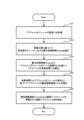
- FIG. 8 is a flow chart showing an example of a pre-wetting method using a plating apparatus. This pre-wetting method is performed by the control module 800 .
- the control module 800 acquires the setting S1 of the pre-wet module 200 (step S10).
- the control module 800 can acquire the setting S1 of the pre-wet module 200 by reading the settings stored in its own memory.
- the control module 800 may acquire the setting S1 of the pre-wet module 200 through communication or external input via an operation panel (not shown).
- the setting S1 of the pre-wet module 200 is a pre-wet process recipe that is predetermined or set by the user, and includes, for example, the number of times the nozzle head 260 scans over the substrate Wf (number of scans Ns). good.
- the setting S1 may also include the scanning distance Ls in one scan of the nozzle head 260 .
- the control module 800 calculates the maximum processing time Tpmax in the pre-wet module 200 based on the rate-determining process that determines the rate of processing in the entire plating apparatus 1000 (step S20).
- the control module 800 detects the rate-determining process that determines the rate of processing in the entire plating apparatus 1000 at a predetermined timing (for example, every predetermined time, or when a new substrate Wf is loaded). good too.
- the plating module 400 can be a module that controls the rate of the entire apparatus (hereinafter also referred to as "rate controlling module").
- the prewetting process by the prewetting module 200 can be executed in parallel with the rate-determining process.
- the pre-wet module 200 has a different installation position in the plating apparatus 1000 than the rate controlling module.
- the rate-determining process is determined by calculating a throughput-related value TH related to the throughput of each process in the plating apparatus 1000 .
- the processing time Ta (seconds) of a certain module M1 in the plating apparatus 1000 and the transfer time Tb (seconds) of the substrate Wf with respect to the module M1 are acquired by actual measurement or simulation, and the module A throughput-related value TH per hour of M1 can be calculated.
- Nm is the number of modules M1 that the plating apparatus 1000 has, and the processes by the modules M1 can be executed in parallel by the number Nm.
- Equation (1) as an example, the unit of the processing time Ta and the transport time Tb is seconds, and the throughput per hour (3600 seconds) is calculated, but it is not limited to this example.
- TH 3600/((Ta+Tb)/Nm) ...(1)
- the rate-limiting module in the plating apparatus 1000 as a whole can be determined. That is, the module with the smallest calculated throughput-related value is the rate-limiting module that rate-controls the entire plating apparatus 1000, and the process executed by the rate-limiting module can be said to be the rate-limiting process.
- the maximum processing time of the prewet module 200 is set so that the prewet process by the prewet module 200 does not become a rate-limiting process, that is, the prewet process is performed at a speed faster than the identified rate-limiting process.
- Tpmax is calculated.
- the maximum processing time Tpmax (seconds) can be calculated by the following equation (2).
- THd means the throughput-related value TH in the rate-determining process
- Npw means the number of pre-wet modules 200 in the plating apparatus 1000 (two in this embodiment). It means the number of pre-wetting processes that can be executed in parallel.
- the maximum processing time Tpmax is calculated in units of “seconds”, but it is not limited to such an example.
- Tpmax (3600/THd) x Npw ...(2)
- the control module 800 subtracts the base time Tbpw of the pre-wet module 200 to calculate the scanning time Tn of the nozzle head 260 (step S30).
- the base time Tbpw corresponds to miscellaneous time excluding the scanning time of the nozzle head 260 in the pre-wet module 200.
- the base time Tbpw includes the time during which the pre-wet module 200 transports the substrate Wf.
- the base time Tbpw a time predetermined by simulation or actual measurement can be used.
- the base time Tbpw may be set in advance and included in the setting S1 of the pre-wet module 200 described above.
- the control module 800 calculates the minimum moving speed Vnmin of the nozzle head 260 based on the scanning time Tn and the setting S1 of the pre-wet module 200 (step S40).
- the number of scans Ns is predetermined, and the product of the number of scans Ns and the scan distance Ls is divided by the scan time Tn as shown in the following equation (3).
- the moving speed Vnmin was calculated.
- the control module 800 is not limited to such an example, and for example, the control module 800 may display the minimum movement speed Vnmin for each scanning count Ns on a display (not shown).
- the minimum movement speed x1 [mm/s]
- the minimum movement speed x2 [mm/s]
- the user viewing the display may be able to select the number of scans Ns of the nozzle head 260 .
- Vnmin (Ns Ls)/Tn ...(3)
- the control module 800 moves (scans) the nozzle head 260 at a speed equal to or higher than the calculated minimum moving speed Vnmin to supply the pre-wet liquid to the substrate Wf (step S50). For example, the control module 800 compares a predetermined recommended speed Vb with a minimum moving speed Vnmin, and if the recommended speed Vb is equal to or higher than the minimum moving speed Vnmin, moves the nozzle head 260 at the recommended speed Vb. may be Further, when the recommended speed Vb is less than the minimum movement speed Vnmin, the control module 800 may move the nozzle head 260 at the minimum movement speed Vnmin.
- the control module 800 may move the nozzle head 260 at the minimum movement speed Vnmin regardless of the value of the minimum movement speed Vnmin. Further, a plurality of recommended speeds Vb1, Vb2, Vb3 may be determined in advance, and the control module 800 may move the nozzle head 260 at the slowest recommended speed equal to or higher than the minimum movement speed Vnmin. With such control, the substrate Wf can be effectively subjected to the pre-wet treatment without the pre-wet treatment limiting the rate of the overall treatment of the plating apparatus 1000 , that is, without affecting the throughput of the plating apparatus 1000 .
- control module 800 may change the pre-wet process conditions while moving the nozzle head 260 during the pre-wet process.
- the control module 800 may change the injection direction (injection center direction) of the prewetting liquid during the prewetting process.
- the pre-wet liquid spraying angle ⁇ n is the first angle (for example, 90 degrees) in the first scan (for example, the first scan), and the second scan (for example, 90 degrees).
- the nozzle head 260 may be driven so that the spraying angle ⁇ n of the prewet liquid is the second angle (eg, 60 degrees).
- the control module 800 may change the distance between the substrate Wf and the nozzle head 260 during the pre-wet process.
- control module 800 may change the amount of pre-wet liquid supplied from the nozzle head 260 or the composition of the pre-wet liquid during the pre-wet process.
- the control module 800 controls at least one of the distance between the substrate Wf and the nozzle head 260, the supply amount of the pre-wet liquid, and the components of the pre-wet liquid in the first scan and the second scan. It is good also as what changes one.
- the substrate Wf can be pre-wet processed under a plurality of conditions, and the pre-wet processing can be performed more effectively. Note that such a change in the pre-wet processing conditions may be determined in advance or set by the user and included in the setting S1 of the pre-wet module 200 described above.
- FIG. 9 is a diagram schematically showing the configuration of a pre-wet module of a modified example.
- 200 A of pre-wet modules of a modification are substantially the same as the pre-wet module 200 of above-described embodiment, attach
- a modified pre-wet module 200A includes a pre-wet tank 280 in addition to the nozzle head 260 .
- the pre-wet tank 280 includes a processing liquid supply line 280a for supplying a processing liquid (pre-wet liquid) into the pre-wet tank 280, and a processing liquid discharge line 280b for discharging the processing liquid from the pre-wet tank 280.
- the pre-wetting tank 280 may store the same processing liquid as the pre-wetting liquid supplied from the nozzle head 260, or may store a different processing liquid.
- the pre-wetting module 200A of the modified example includes a drive mechanism 248 configured to switch the state of the pre-wetting stage 240 between a state in which the substrate Wf is directed upward and a state in which the substrate Wf is directed downward.
- the drive mechanism 248 can be realized by a known mechanism such as a motor.
- the substrate Wf (surface to be plated Wf-a) is directed upward by the driving mechanism 248, and the prewetting liquid is supplied from the nozzle head 260 to perform the prewetting process in the same manner as described above. can apply.
- the drive mechanism 248 is configured to move the pre-wetting stage 240 (substrate Wf) vertically while the substrate Wf (surface to be plated Wf-a) faces downward.
- the prewetting module 200A may cause the prewetting liquid to act on the substrate Wf by supplying the processing liquid from the processing liquid supply line 280a after moving the prewetting stage 240 into the prewetting tank 280. good.
- the prewet module 200A may apply the processing liquid to the substrate Wf by moving the prewetting stage 240 into the prewet tank 280 while the processing liquid is stored in the prewet tank 280. .
- pre-wet liquid can be supplied from the nozzle head 260 and pre-wet processing can be performed in the same manner as the pre-wet module 200 of the above-described embodiment.
- pre-wet treatment can be performed by causing the treatment liquid stored in the pre-wet tank 280 to act on the substrate Wf.
- the base time Tbpw (see step S30 in FIG. 9) preferably includes the time for immersing the substrate Wf in the processing liquid in the prewet tank 280.
- the time for immersing the substrate Wf in the processing liquid in the pre-wet bath 280 may be included in the setting S1 of the pre-wet module 200 .
- the present invention can also be described as the following forms.
- Mode 1 According to mode 1, there is proposed a pre-wet treatment method for performing pre-wet treatment before plating a substrate in a plating apparatus.
- the plating apparatus includes a plating module for performing the plating process on the substrate, and a pre-wet module for performing the pre-wet process on the substrate.
- the pre-wet module has a nozzle head configured to supply pre-wet liquid to the surface of the substrate while moving along the surface of the substrate.
- the pre-wet processing method includes a step of calculating a maximum processing time in the pre-wet module based on a rate-limiting step that controls the processing in the entire plating apparatus; calculating a minimum moving speed of the head; and moving the nozzle head at a speed equal to or higher than the calculated minimum moving speed to supply the pre-wet liquid to the plate surface of the substrate.
- the pre-wet treatment can be effectively applied to the substrate without affecting the throughput.
- Mode 2 in Mode 1, the step of calculating the minimum moving speed is based on the maximum processing time and the number of times the nozzle head scans the plate surface. Calculate According to form 2, the minimum moving speed of the nozzle head can be calculated based on the number of times the nozzle head is scanned.
- the plating apparatus includes a predetermined number of rate-limiting modules for performing the rate-limiting process, and the step of calculating the maximum processing time is the processing time by the rate-limiting module. and calculating a throughput-related value of the plating apparatus by dividing the sum of the transfer time and the transfer time related to the rate-limiting module by the predetermined number.
- the maximum processing time of the pre-wet module can be calculated based on the throughput-related value.
- Mode 4 in Modes 1 to 3, in the step of supplying the pre-wet liquid, the nozzle head scans the plate surface a predetermined number of times, and the nozzle head The spraying angle of the pre-wet liquid with respect to the plate surface is a first angle, and the spraying angle is a second angle different from the first angle in the second scan. According to Mode 4, the pre-wet liquid can be sprayed onto the plate surface of the substrate at different angles for each scan.
- the step of supplying the pre-wet liquid includes scanning the plate surface with the nozzle head a predetermined number of times, and the amount of the pre-wet liquid supplied from the nozzle head or the components of the pre-wet liquid differ.
- the step of calculating the minimum moving speed includes subtracting a base time including a transport time of the substrate with respect to the pre-wet module from the maximum processing time. Including calculating the scan time of the nozzle head. According to form 6, the scanning time of the nozzle head can be calculated based on the base time of the pre-wet module.
- the pre-wet module has a pre-wet tank for accommodating the substrate and immersing the substrate in the processing liquid, and the base time includes the A time is included for immersing the substrate in the processing solution in a pre-wet bath.
- the substrate can be immersed in the processing liquid in the pre-wet bath.
- the scanning time of the nozzle head can be calculated taking into account the time required for immersing the substrate in the processing liquid.
- Mode 8 According to Mode 8, in Modes 1 to 7, the rate-determining step is a step performed in the plating module.
- Mode 9 According to Mode 9, in Modes 1 to 8, the plating module is provided at a first position, and the pre-wetting module is provided at a second position different from the first position.
- Mode 10 According to Mode 10, in Modes 1 to 9, the step of supplying the prewet liquid is performed with the surface to be plated of the substrate facing upward.
Landscapes
- Chemical & Material Sciences (AREA)
- Engineering & Computer Science (AREA)
- Chemical Kinetics & Catalysis (AREA)
- Electrochemistry (AREA)
- Materials Engineering (AREA)
- Metallurgy (AREA)
- Organic Chemistry (AREA)
- Life Sciences & Earth Sciences (AREA)
- Sustainable Development (AREA)
- Automation & Control Theory (AREA)
- Electroplating Methods And Accessories (AREA)
- Chemically Coating (AREA)
Priority Applications (4)
| Application Number | Priority Date | Filing Date | Title |
|---|---|---|---|
| JP2022531464A JP7101925B1 (ja) | 2021-10-14 | 2021-10-14 | プリウェット処理方法 |
| KR1020227042093A KR102604588B1 (ko) | 2021-10-14 | 2021-10-14 | 프리웨트 처리 방법 |
| PCT/JP2021/038049 WO2023062778A1 (ja) | 2021-10-14 | 2021-10-14 | プリウェット処理方法 |
| CN202180042509.0A CN115715337B (zh) | 2021-10-14 | 2021-10-14 | 预湿处理方法 |
Applications Claiming Priority (1)
| Application Number | Priority Date | Filing Date | Title |
|---|---|---|---|
| PCT/JP2021/038049 WO2023062778A1 (ja) | 2021-10-14 | 2021-10-14 | プリウェット処理方法 |
Publications (1)
| Publication Number | Publication Date |
|---|---|
| WO2023062778A1 true WO2023062778A1 (ja) | 2023-04-20 |
Family
ID=82446222
Family Applications (1)
| Application Number | Title | Priority Date | Filing Date |
|---|---|---|---|
| PCT/JP2021/038049 WO2023062778A1 (ja) | 2021-10-14 | 2021-10-14 | プリウェット処理方法 |
Country Status (4)
| Country | Link |
|---|---|
| JP (1) | JP7101925B1 (zh) |
| KR (1) | KR102604588B1 (zh) |
| CN (1) | CN115715337B (zh) |
| WO (1) | WO2023062778A1 (zh) |
Citations (2)
| Publication number | Priority date | Publication date | Assignee | Title |
|---|---|---|---|---|
| WO2010148147A2 (en) * | 2009-06-17 | 2010-12-23 | Novellus Systems, Inc. | Apparatus for wetting pretreatment for enhanced damascene metal filling |
| WO2020028012A1 (en) * | 2018-07-30 | 2020-02-06 | Lam Research Corporation | System and method for chemical and heated wetting of substrates prior to metal plating |
Family Cites Families (10)
| Publication number | Priority date | Publication date | Assignee | Title |
|---|---|---|---|---|
| JP4664320B2 (ja) * | 2000-03-17 | 2011-04-06 | 株式会社荏原製作所 | めっき方法 |
| JP2001316869A (ja) * | 2000-05-08 | 2001-11-16 | Tokyo Electron Ltd | 電解メッキ方法 |
| JP4624738B2 (ja) * | 2003-08-21 | 2011-02-02 | 株式会社荏原製作所 | めっき装置 |
| JP5232844B2 (ja) * | 2003-08-21 | 2013-07-10 | 株式会社荏原製作所 | めっき装置 |
| JP2005264245A (ja) * | 2004-03-18 | 2005-09-29 | Ebara Corp | 基板の湿式処理方法及び処理装置 |
| JP7067863B2 (ja) * | 2016-12-28 | 2022-05-16 | 株式会社荏原製作所 | 基板を処理するための方法および装置 |
| JP2019085613A (ja) * | 2017-11-07 | 2019-06-06 | 株式会社荏原製作所 | 前処理装置、これを備えためっき装置、及び前処理方法 |
| JP7291030B2 (ja) * | 2018-09-06 | 2023-06-14 | 株式会社荏原製作所 | 基板処理装置 |
| JP2020204062A (ja) * | 2019-06-14 | 2020-12-24 | 株式会社荏原製作所 | めっき方法、プログラムを記憶する不揮発性の記憶媒体 |
| US20220396897A1 (en) * | 2020-12-22 | 2022-12-15 | Ebara Corporation | Plating apparatus, pre-wet process method, and cleaning process method |
-
2021
- 2021-10-14 JP JP2022531464A patent/JP7101925B1/ja active Active
- 2021-10-14 KR KR1020227042093A patent/KR102604588B1/ko active IP Right Grant
- 2021-10-14 WO PCT/JP2021/038049 patent/WO2023062778A1/ja active Application Filing
- 2021-10-14 CN CN202180042509.0A patent/CN115715337B/zh active Active
Patent Citations (2)
| Publication number | Priority date | Publication date | Assignee | Title |
|---|---|---|---|---|
| WO2010148147A2 (en) * | 2009-06-17 | 2010-12-23 | Novellus Systems, Inc. | Apparatus for wetting pretreatment for enhanced damascene metal filling |
| WO2020028012A1 (en) * | 2018-07-30 | 2020-02-06 | Lam Research Corporation | System and method for chemical and heated wetting of substrates prior to metal plating |
Also Published As
| Publication number | Publication date |
|---|---|
| CN115715337A (zh) | 2023-02-24 |
| JPWO2023062778A1 (zh) | 2023-04-20 |
| CN115715337B (zh) | 2023-09-08 |
| JP7101925B1 (ja) | 2022-07-15 |
| KR20230054318A (ko) | 2023-04-24 |
| KR102604588B1 (ko) | 2023-11-22 |
Similar Documents
| Publication | Publication Date | Title |
|---|---|---|
| US20030010449A1 (en) | Automatic wafer processing and plating system | |
| US6558750B2 (en) | Method of processing and plating planar articles | |
| US11542619B2 (en) | Plating method | |
| WO2023062778A1 (ja) | プリウェット処理方法 | |
| CN114981484B (zh) | 镀覆装置、以及镀覆处理方法 | |
| TW202317278A (zh) | 預濕處理方法 | |
| US20030013285A1 (en) | Method of processing and plating wafers and other planar articles | |
| KR102595617B1 (ko) | 도금 방법 및 도금 장치 | |
| US20230167572A1 (en) | Wetting method for substrate and plating apparatus | |
| JP7253125B1 (ja) | めっき装置、及び、めっき方法 | |
| WO2024048106A1 (ja) | 基板処理装置 | |
| JP7162787B1 (ja) | めっき装置 | |
| US11542629B2 (en) | Method of plating, apparatus for plating, and non-volatile storage medium that stores program | |
| WO2023248416A1 (ja) | プリウェットモジュール、およびプリウェット方法 | |
| JP7142812B1 (ja) | リーク判定方法およびめっき装置 | |
| TWI809937B (zh) | 漏液判定方法及鍍覆裝置 | |
| TWI746334B (zh) | 鍍覆裝置及鍍覆處理方法 | |
| WO2023032191A1 (ja) | めっき方法及びめっき装置 | |
| WO2022254485A1 (ja) | プリウェットモジュール、およびプリウェット方法 | |
| KR102493757B1 (ko) | 도금 장치 | |
| JP7460504B2 (ja) | めっき装置 | |
| TWI837780B (zh) | 鍍覆裝置及鍍覆方法 | |
| WO2022185523A1 (ja) | めっきモジュールを調整する方法 | |
| TW202409358A (zh) | 鍍覆裝置及鍍覆方法 | |
| KR20240043687A (ko) | 기판 처리 장치 및 기판 처리 방법 |
Legal Events
| Date | Code | Title | Description |
|---|---|---|---|
| WWE | Wipo information: entry into national phase |
Ref document number: 2022531464 Country of ref document: JP |
|
| WWE | Wipo information: entry into national phase |
Ref document number: 18016301 Country of ref document: US |
|
| 121 | Ep: the epo has been informed by wipo that ep was designated in this application |
Ref document number: 21960635 Country of ref document: EP Kind code of ref document: A1 |