WO2023053329A1 - 相間絶縁紙、モータ、相間絶縁紙の組付方法 - Google Patents
相間絶縁紙、モータ、相間絶縁紙の組付方法 Download PDFInfo
- Publication number
- WO2023053329A1 WO2023053329A1 PCT/JP2021/036100 JP2021036100W WO2023053329A1 WO 2023053329 A1 WO2023053329 A1 WO 2023053329A1 JP 2021036100 W JP2021036100 W JP 2021036100W WO 2023053329 A1 WO2023053329 A1 WO 2023053329A1
- Authority
- WO
- WIPO (PCT)
- Prior art keywords
- insulating paper
- stator core
- circumferential direction
- phase
- pair
- Prior art date
- Legal status (The legal status is an assumption and is not a legal conclusion. Google has not performed a legal analysis and makes no representation as to the accuracy of the status listed.)
- Ceased
Links
Images


Classifications
-
- H—ELECTRICITY
- H02—GENERATION; CONVERSION OR DISTRIBUTION OF ELECTRIC POWER
- H02K—DYNAMO-ELECTRIC MACHINES
- H02K3/00—Details of windings
- H02K3/32—Windings characterised by the shape, form or construction of the insulation
- H02K3/34—Windings characterised by the shape, form or construction of the insulation between conductors or between conductor and core, e.g. slot insulation
-
- H—ELECTRICITY
- H02—GENERATION; CONVERSION OR DISTRIBUTION OF ELECTRIC POWER
- H02K—DYNAMO-ELECTRIC MACHINES
- H02K15/00—Processes or apparatus specially adapted for manufacturing, assembling, maintaining or repairing of dynamo-electric machines
- H02K15/10—Applying solid insulation to windings, stators or rotors, e.g. applying insulating tapes
-
- H—ELECTRICITY
- H02—GENERATION; CONVERSION OR DISTRIBUTION OF ELECTRIC POWER
- H02K—DYNAMO-ELECTRIC MACHINES
- H02K3/00—Details of windings
- H02K3/32—Windings characterised by the shape, form or construction of the insulation
- H02K3/34—Windings characterised by the shape, form or construction of the insulation between conductors or between conductor and core, e.g. slot insulation
- H02K3/345—Windings characterised by the shape, form or construction of the insulation between conductors or between conductor and core, e.g. slot insulation between conductor and core, e.g. slot insulation
-
- H—ELECTRICITY
- H02—GENERATION; CONVERSION OR DISTRIBUTION OF ELECTRIC POWER
- H02K—DYNAMO-ELECTRIC MACHINES
- H02K3/00—Details of windings
- H02K3/32—Windings characterised by the shape, form or construction of the insulation
- H02K3/38—Windings characterised by the shape, form or construction of the insulation around winding heads, equalising connectors, or connections thereto
Definitions
- the present invention relates to an interphase insulating paper, a motor, and a method for assembling the interphase insulating paper.
- JP2007-60819A describes interphase insulating paper for ensuring insulation between U phase and V phase, interphase insulating paper for ensuring insulation between V phase and W phase, and between W phase and U phase in a three-phase motor. It discloses that interphase insulating papers are individually provided to ensure insulation, and each interphase insulating paper is individually mounted in a slot of a stator core.
- JP2007-60819A since the individually provided interphase insulating papers are sequentially installed in the slots of the stator core, the interphase insulating paper that is installed first generates a force that pushes out the interphase insulating paper that is installed later to the inner peripheral side of the stator core. , it becomes difficult to install interphase insulating paper.
- An object of the present invention is to provide an interphase insulating paper that facilitates mounting in slots of a stator core, a motor equipped with the interphase insulating paper, and a method for assembling the interphase insulating paper.
- the interphase insulating paper is composed of a plurality of insulating papers arranged so as to circulate in the circumferential direction in the stator core, and performs interphase insulation of each phase coil provided in the stator core with the plurality of insulating papers.
- the insulating paper includes a pair of legs inserted into a pair of slots of the plurality of slots formed in the stator core, and a pair of legs connected to the pair of legs and protruding from both end surfaces of the stator core in the axial direction. a pair of flat portions for providing phase-to-phase insulation of the coil, the pair of legs being connected to the central portions of the edges of the flat portions.
- FIG. 1 is a schematic diagram of an insulating paper that constitutes the interphase insulating paper of this embodiment.
- FIG. 2 is a diagram showing a case in which the insulating paper of the present embodiment is attached to the stator core and is developed in the circumferential direction of the stator core.
- FIGS. 3A and 3B are diagrams for explaining insulating paper constituting interphase insulating paper of a comparative example.
- FIG. 3A is a plan view of the insulating paper of the comparative example
- FIG. 3B is the insulating paper of the comparative example.
- Fig. 3(c) shows a case in which the insulating paper of the comparative example protrudes from the slot when it is inserted into the stator core.
- FIG. 3(c) shows a case in which the insulating paper of the comparative example protrudes from the slot when it is inserted into the stator core.
- FIG. 10 is a diagram showing a case where the terminal is popped out of the slot by receiving a force from the slot.
- FIG. 4 is a diagram (copy) showing a mounting state of the insulating paper of the comparative example.
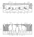
- 5A and 5B are diagrams showing the process of assembling the interphase insulating paper according to the present embodiment
- FIG. b) is a view of the planar portion of the insulating paper on the outer peripheral side viewed from the axial direction.
- 6A and 6B are diagrams showing the process of assembling the phase-to-phase insulating paper according to the present embodiment.
- FIG. 6B is a diagram showing a state in which the legs of the inner peripheral insulating paper are inserted into the slots in which the phase coils are mounted, and FIG. be.
- FIG. 7 is a view showing the process of assembling the phase-to-phase insulating paper according to the present embodiment, showing a state in which the W-phase coil is mounted in the slot into which the leg portion of the insulating paper on the inner peripheral side is inserted.
- FIG. 8 is a diagram (copy) showing the process of assembling the interphase insulating paper according to the present embodiment, showing a state after the insulating paper on the inner peripheral side is inserted into the slot.
- FIG. 9 is a diagram (copy) showing the step of assembling the interphase insulating paper according to the present embodiment.
- FIG. 9(a) shows the case where the plane portion has no arc portion
- FIG. 9(b) shows the case where the plane portion has the arc portion.
- 10A and 10B are diagrams (reproduction) showing the process of assembling the interphase insulating paper according to the present embodiment, in which FIG. ) indicates the state after bundling.
- FIG. 1 is a schematic diagram of an insulating paper 1 that constitutes the interphase insulating paper of this embodiment.
- the interphase insulating paper of this embodiment is composed of a plurality of insulating papers 1 that are mounted in slots 21 of a stator core 2 of a motor (not shown) so as to circulate in the circumferential direction of the stator core 2 .
- the phase-to-phase insulation paper provides phase-to-phase insulation between each phase coil (U-phase coil U, V-phase coil V, and W-phase coil W) mounted on the stator core 2 .
- the motor is used for driving a vehicle, for example.
- the motor functions as an electric motor that receives power from a power supply such as a battery and rotates to drive the wheels of the vehicle.
- the motor also functions as a generator that is driven by an external force to generate electricity. That is, the motor is configured as a so-called motor generator that functions as an electric motor and a generator.
- the motor may be used as a drive source for a system other than the vehicle, instead of the motor for driving the vehicle.
- the insulating paper 1 of this embodiment has a shape in which two rectangular flat portions 12 are connected by two leg portions 11, and has a planar shape without irregularities before being attached to the stator core 2.
- the insulating paper 1 is made of, for example, a three-layer laminated material in which aramid fiber paper is laminated on both sides of a polyethylene terephthalate (PEN) film, and is formed by punching using a dedicated mold.
- PEN polyethylene terephthalate
- the leg portion 11 is connected to the edge of the flat portion 12 and to the central portion of the flat portion 12 in the longitudinal direction (the circumferential direction of the stator core 2).
- the leg portion 11 has a longitudinal dimension that is substantially the same as the axial length of the stator core 2 (slot 21), and a width dimension that is equal to or less than the circumferential width of the outermost inner wall of the slot 21, for example. It is the part that has The leg portion 11 is inserted through the groove of the slot 21 .
- a long hole portion 13 is provided between the leg portions 11 .
- the long hole portion 13 is a rectangular opening having a width dimension equal to or larger than the circumferential width of the teeth 22 between the slots 21 .
- the teeth 22 are inserted into the elongated holes 13 when the leg portion 11 is inserted into the slots 21 .
- the flat portion 12 is a substantially rectangular member, and is formed to protrude from both ends of the stator core 2 in the axial direction when the leg portion 11 is inserted into the slot 21 .
- the longitudinal direction of the flat portion 12 is orthogonal to the longitudinal direction of the leg portion 11 , and when the leg portion 11 is inserted into the slot 21 , it is arranged along the circumferential direction of the stator core 2 .
- the plane portion 12 is arranged so as to insulate the coil ends (portions protruding from the slots 21) of the coils of each phase.
- the circular arc portion 15 is a notch formed in the edge of the planar portion 12 facing the stator core 2 .
- the arc portion 15 is formed in an arc shape following the shape of the portion protruding from the slot 21 of each phase coil.
- the notch 14 (notch) is arranged in a portion of the flat portion 12 that forms the short side of the elongated hole portion 13 .
- the notch 14 is used for positioning the wire 4 and guiding the cutting of the plane portion 12, which will be described later.
- FIG. 2 is a diagram showing a case in which the insulating paper 1 of the present embodiment is attached to the stator core 2 and is developed in the circumferential direction of the stator core 2. As shown in FIG. Although FIG. 2 shows only one side of the stator core 2 in the axial direction, the arrangement relationship between each phase coil and the insulating paper 1 is the same on the lead side (the side that exchanges current with the outside) and the opposite lead side. .
- a plurality of in-phase coils are mounted on the stator core 2 in a state of being arranged in the circumferential direction (see FIG. 7).
- the same number of insulating papers 1 as the number of coils of the same phase are arranged in the circumferential direction of the stator core 2.
- the insulating papers 1 are arranged so that the planar portions 12 of the insulating papers 1 adjacent to each other in the circumferential direction overlap each other in the circumferential direction.
- the length of the flat portion 12 in the circumferential direction is A
- the amount of displacement of the insulating papers 1 adjacent to each other in the circumferential direction that is, the length of the insulating papers 1 adjacent to each other is inserted into the elongated holes 13 of the adjacent insulating papers 1, respectively.
- the circumferential interval between the pair of teeth 22 to be connected is B
- the relationship A>B is established.
- the stator core 2 includes a U-phase coil U (first-phase coil), a V-phase coil V (second-phase coil), and a W-phase coil W (second-phase coil) distributed winding. are arranged so that The widths of the U-phase coil U, the V-phase coil V, and the W-phase coil W in the circumferential direction are the same.
- the V-phase coil V is displaced from the U-phase coil U by two slots 21, for example, in one circumferential direction (left side in FIG. 2), and the W-phase coil W is the U-phase coil. It is arranged at a position displaced by four slots 21 in one circumferential direction (left side in FIG. 2) with respect to U, for example.
- the insulating paper 1 is arranged so that teeth 22 sandwiched by a pair of V-phase coils V (or other phases) adjacent to each other in the circumferential direction are inserted into the elongated holes 13 . Also, the insulating paper 1 is arranged so that teeth 22 sandwiched by a pair of W-phase coils W (other phases may be used) adjacent to each other in the circumferential direction are inserted into the elongated holes 13, as will be described later.
- the legs 11 are connected to the central portion of the plane portion 12 in the longitudinal direction, thereby forming a symmetrical shape.
- the leg portion 11 may be connected to a position displaced from the center portion in the longitudinal direction of the flat portion 12 to one side in the longitudinal direction, and the insulating paper 1 may be left-right asymmetrical.
- the pair of legs 11 are arranged so as to sandwich one tooth 22, but they may be connected to the plane portion 12 so as to straddle two or more teeth 22. .
- the length of the planar portion 12 of the insulating paper 1 in the circumferential direction is the same as that of a pair of insulating papers 1 adjacent to each other when a plurality of the insulating papers 1 are mounted so as to circulate in the circumferential direction of the stator core 2 .
- the flat portions 12 may be set so as to overlap each other in the circumferential direction.
- FIG. 3A and 3B are diagrams for explaining an insulating paper 1X constituting an interphase insulating paper of a comparative example
- FIG. 3A is a plan view of the insulating paper 1X of the comparative example
- FIG. 3C is a diagram showing a case where the insulating paper 1X protrudes by itself from the slot 21 when the insulating paper 1X is inserted into the stator core 2
- FIG. 10 is a diagram showing a case where the paper 1X receives force from the previously inserted insulating paper 1X and pops out of the slot 21
- FIG. 4 is a diagram (copy) showing a mounting state of the insulating paper 1X of the comparative example.
- FIG. 4 shows a case where the insulating paper 1X of the comparative example is attached after the V-phase coil V is attached.
- a plurality of insulating papers 1X of the comparative example are installed in the slots 21 so as to circulate in the circumferential direction of the stator core 2 in the same manner as the insulating papers 1 of the present embodiment.
- the insulating paper 1X has a flat portion 12 and leg portions 16, and the leg portions 16 are arranged at both ends of the flat portion 12 in the longitudinal direction (circumferential direction).
- the insulating paper 1X of the comparative example is similar to the insulating paper disclosed in JP2007-60819A. Similar to the insulating paper 1 of the present embodiment, the insulating paper 1X of the comparative example is mounted on the stator core 2 in a state in which a plurality (eight sheets) are arranged in the circumferential direction of the stator core 2 (see FIG. 4), and the insulating papers 1X adjacent to each other 1 are mounted in such a manner that they overlap each other in the circumferential direction by one slot 21 (see FIG. 3(c)).
- a plurality of U-phase coils U (may be started from coils of other phases) are attached to the stator core 2 in the circumferential direction, and the insulating paper is attached.
- a plurality of 1X are mounted on the stator core 2 so as to circulate in the circumferential direction.
- a plurality of V-phase coils V are mounted on the stator core 2 so as to circulate in the circumferential direction, and are insulated.
- a plurality of sheets of paper 1X are mounted around the stator core 2 in the circumferential direction. Then, after bending the V-phase coil V (coil end) and the flat portion 12 of the insulating paper 1X attached later to the outer peripheral side of the stator core 2, a plurality of W-phase coils W are attached so as to circulate around the stator core 2 in the circumferential direction. (see FIGS. 5-7).
- the insulating paper 1X of the comparative example is flat in the initial state, but since the coil end after molding has a complicated shape, it interferes with the coil end when the insulating paper 1X is mounted in the slot 21.
- the entire insulating paper 1X cannot stay in the circumferential direction of the stator core 2 and can move toward the inner diameter side of the stator core 2 (see FIGS. 3(b) and 4).
- the legs 16 of the insulating paper 1X protrude from the grooves of the slots 21 of the stator core 2, causing a problem that the coil of the next phase cannot be inserted (see the enlarged view at the top of FIG. 4).
- the insulating paper 1X of the comparative example When the insulating paper 1X of the comparative example is inserted into the stator core 2, the insulating paper 1X is deformed into an arc shape or an S-shape. . At this time, the insulating paper 1X that is inserted later is pushed by the insulating paper 1X that has been inserted first, so the leg portion 16 can protrude from the groove of the slot 21 (see FIG. 5C and the lower enlarged view of FIG. 6). There is a problem.
- the insulating paper 1X that has been attached once protrudes toward the inner diameter side of the stator core 2 before the coil is inserted in the next process, and the insulating paper 1X is separated from between the coils or the position of the insulating paper 1X is displaced. There is a problem that arises.
- the insulating paper 1X when the insulating paper 1X is assembled to the stator core 2, the insulating paper 1X is placed between the first phase coil (U-phase coil U) and the second phase coil (V-phase coil V) and between the second phase coil ( It is inserted between the V-phase coil V) and the third-phase coil (W-phase coil W), and deforms into a three-dimensional shape at each insertion position.
- the insulating paper 1X in order to reduce the protrusion of the insulating paper 1X toward the inner diameter side, it is conceivable to provide the insulating paper 1X with creases in advance corresponding to the insertion position of the stator core 2 so that the insulating paper 1X has a three-dimensional shape.
- Insulating paper 1 can be installed in slots 21 of stator core 2 .
- FIG. 5A and 5B are diagrams showing the steps of assembling the interphase insulating paper according to the present embodiment
- FIG. 5(b) is a view of the flat portion 12 of the insulating paper 1 on the outer peripheral side as seen from the axial direction
- 6A and 6B are diagrams showing the steps of assembling the phase-to-phase insulating paper according to the present embodiment.
- FIG. 6B is a view showing a state in which the leg portion 11 of the inner peripheral insulating paper 1 is inserted into the slot 21 in which the W-phase coil W is installed
- FIG. It is the figure which looked at the part 12 from the axial direction.
- FIG. 7 is a diagram showing the process of assembling the interphase insulating paper according to the present embodiment, showing a state in which the W-phase coil W is mounted in the slot 21 into which the leg portion 11 of the insulating paper 1 on the inner peripheral side is inserted. It is a diagram. 5 to 7, illustration of coil ends of each phase coil is omitted.
- the stator core 2 to which the insulating paper 1 of this embodiment is applied has 48 slots 21 and teeth 22 as shown in FIG. Eight U-phase coils U (U1-U8), V-phase coils V (V1-V8), and W-phase coils W (W1-W8) are prepared and mounted in slots 21, respectively.
- U-phase coils U (U1 to U8) are installed in slots 21, and insulating paper 1 ((1) to (8)) is installed in slots 21 in which V-phase coils V are installed. Insert the leg portion 11 of (the first interphase insulating paper).
- the legs 11 of the insulating paper 1 (1) are inserted into the slots 21 (V1) and 21 (V2), respectively.
- the leg 11 is illustrated at a position away from the slot 21 (V1) and the slot 21 (V2), and the same applies hereinafter.
- the legs 11 of the insulating paper 1 (2) are inserted into the slots 21 (V2) and 21 (V3), respectively, and the legs 11 of the insulating paper 1 (3) are inserted into the slots 21 (V3) and 21 (V3).
- 21 (V4), and the legs 11 of the insulating paper 1 (4) are inserted into the slots 21 (V4) and 21 (V5), respectively.
- the legs 11 of the insulating paper 1 (5) are inserted into the slots 21 (V5) and 21 (V6), respectively, and the legs 11 of the insulating paper 1 (6) are inserted into the slots 21 (V6) and 21 (V6).
- 21 (V7), the legs 11 of the insulating paper 1 (7) are inserted into the slots 21 (V7) and 21 (V8), respectively, and the legs 11 of the insulating paper 1 (8) are inserted into the slots. 21 (V8) and slot 21 (V1).
- the legs 11 of the insulating paper 1 ((1) to (8)) are arranged on the inner wall side of the outermost periphery of the slot 21, and the portion of the planar portion 12 overlapping the U-phase coil U in the circumferential direction is the stator core 2.
- the insulating paper 1 is deformed into a three-dimensional shape shown in FIG. 5(b).
- V-phase coils V (V1 to V8) are installed in slots 21, and insulating paper 1 ((9) to (16)) is installed in slots 21 in which W-phase coils W are installed. Insert the leg portion 11 of (the second interphase insulating paper).
- the legs 11 of the insulating paper 1 (9) are inserted into the slots 21 (W1) and 21 (W2), respectively, and the legs 11 of the insulating paper 1 (10) are inserted into the slots 21 (W2) and 21 (W2).
- 21 (W3) the legs 11 of the insulating paper 1 (11) are inserted into the slots 21 (W3) and 21 (W4), respectively, and the legs 11 of the insulating paper 1 (12) are inserted into the slots.
- 21 (W4) and slot 21 (W5) are inserted into the slots 21 (W1) and 21 (W2)
- the legs 11 of the insulating paper 1 (13) are inserted into the slots 21 (W5) and 21 (W6), respectively, and the legs 11 of the insulating paper 1 (14) are inserted into the slots 21 (W6) and 21 (W6).
- 21 (W7), the legs 11 of the insulating paper 1 (15) are inserted into the slots 21 (W7) and 21 (W8), respectively, and the legs 11 of the insulating paper 1 (16) are inserted into the slots. 21 (W8) and slot 21 (W1).
- the legs 11 of the insulating paper 1 ((9) to (16)) are arranged on the inner wall side of the outermost periphery of the slot 21, and overlap the U-phase coil U and the V-phase coil V in the circumferential direction on the plane portion 12. 6 ( b) It is deformed into a three-dimensional shape shown in FIG.
- the coil ends of the U-phase coil U are bundled with an insulating wire 4 (see FIG. 10), and the coil ends of the V-phase coil V and the outer insulating paper 1 ((1) to (8)) are connected with the wire 4.
- the coil end of the W-phase coil W and the inner insulating paper 1 ((9) to (16)) are bundled with a wire 4, and then each phase coil is coated with varnish (not shown).
- FIG. 8 is a diagram (copy) showing the process of assembling the interphase insulating paper according to the present embodiment, showing a state after the insulating paper 1 on the inner peripheral side has been inserted into the slot 21.
- the flat portion 12 of the insulating paper 1 ((1) to (8)) on the outer peripheral side is bent together with the V-phase coil V toward the outer peripheral side.
- the planar portion 12 of the insulating paper 1 can be deformed without being damaged. Further, as described above, if A is the circumferential length of the plane portion 12 and B is the circumferential interval between the pair of teeth 22 inserted into the long hole portions 13 of the insulating paper 1 adjacent to each other, then A >B relationship is established.
- the flat portion 12 of the insulating paper 1 ((1) to (8)) (see FIG. 7) arranged on the outer peripheral side is bent to the outer peripheral side of the stator core 2 together with the U-phase coil U. Even so, the plane portions 12 of the insulating papers 1 that are adjacent to each other in the circumferential direction can be maintained to overlap each other in the circumferential direction, and the insulation between the U-phase coil U and the V-phase coil V can be maintained.
- FIG. 8 it can be seen that the legs 11 of the insulating paper 1 ((9) to (16)) (FIG. 7) arranged on the inner peripheral side do not protrude from the groove of the slot 21. The same applies to the insulating paper 1 ((1) to (8)) (FIG. 7) arranged on the outer peripheral side.
- the central portion in the circumferential direction of the insulating paper 1 (the central portion in the circumferential direction of the plane portion 12 and the leg portion 11) is hardly deformed. can be reliably inserted into a pair of slots 21 adjacent to each other. Therefore, it is possible to reduce the restoring force that may occur due to the deformation of the flat portion 12 and the leg portion 11 . Therefore, the insulating paper 1 does not rotate when it is attached to the stator core 2 , and is semi-fixed to the stator core 2 only by attaching the leg portions 11 to the slots 21 .
- the circumferential central portion of the insulating paper 1 (the circumferential central portion of the planar portion 12 and the leg portion 11) is Almost no deformation or displacement.
- the width direction of the leg portion 11 is not deformed so as to face the groove of the slot 21, and the center portion of the flat portion 12 in the circumferential direction is substantially deformed toward the inner circumference side of the stator core 2. Therefore, the leg portion 11 hardly displaces toward the groove side of the slot 21 . Therefore, protrusion of the leg portion 11 from the groove of the slot 21 can be reduced.
- FIG. 9 is a diagram (copy) showing the process of assembling the phase-to-phase insulating paper according to the present embodiment.
- 9(a) shows a state in which the flat portion 12 has no arc portion 15
- FIG. 9(b) shows a case in which the flat portion 12 has the arc portion 15.
- FIG. 9(a) shows a state in which the flat portion 12 has no arc portion 15
- FIG. 9(b) shows a case in which the flat portion 12 has the arc portion 15.
- each phase coil and insulating paper 1 As described above, after the step of assembling each phase coil and insulating paper 1 to the stator core 2, the coil ends of each phase coil are bundled with wires 4 (see FIG. 10), and then each phase coil is coated with varnish. , the wire 4 is omitted in FIG.
- the insulating paper 1 of the present embodiment does not have the arc portion 15 shown in FIG. 1 and the plane portion 12 is rectangular, as shown in FIG. Since the U coil ends are covered more than necessary, application of varnish to the U-phase coil U may be complicated.
- FIGS. 10A and 10B are diagrams (copy) showing the process of assembling the interphase insulating paper according to the present embodiment, FIG. (b) shows the state after bundling.
- FIG. 10 shows a case where the U-phase coil U and the insulating paper 1 are bundled.
- notch 14 is arranged at the position where The wires 4 are anchored in the notches 14 when the coils of each phase and the insulating paper 1 are bundled with the wires 4 .
- the plane portion 12 is not divided in the circumferential direction, so the insulation between the phase coils by the plane portion 12 is maintained.
- the legs 11 can be prevented from being cut, and cuts can be formed in the insulating paper 1 in the intended direction.
- the stator core 2 is composed of a plurality of insulating papers 1 arranged so as to circulate in the circumferential direction.
- Insulating paper 1 includes a pair of legs 11 inserted into a pair of slots 21 out of a plurality of slots 21 formed in stator core 2, and a pair of legs 11 connected to the pair of legs 11. and a pair of flat portions 12 protruding from both end surfaces in the axial direction of the stator core 2 to perform inter-phase insulation of each phase coil, and the pair of leg portions 11 are connected to the central portions of the edges of the flat portions 12.
- the circumferential central portion of the insulating paper 1 (the circumferential central portion of the flat portion 12 and the leg portions 11) is hardly deformed before and after the slot 21 of the insulating paper 1 is attached, and the pair of The legs 11 can be reliably inserted into the pair of slots 21 adjacent to each other. Therefore, it is possible to reduce the restoring force that may occur due to the deformation of the flat portion 12 and the leg portion 11 .
- the circumferential central portion of the insulating paper 1 (the circumferential central portion of the flat portion 12 and the leg portion 11) is mostly deformed. No displacement. Specifically, the width direction of the leg portion 11 is not deformed so as to face the groove of the slot 21, and the center portion of the flat portion 12 in the circumferential direction is substantially deformed toward the inner circumference side of the stator core 2. Therefore, the leg portion 11 hardly displaces toward the groove side of the slot 21 . Therefore, the protrusion of the legs 11 from the grooves of the slots 21 can be reduced, and the insulating paper 1 can be easily attached to the slots 21 of the stator core 2 .
- A is the circumferential length of the flat portion 12 and B is the amount of circumferential displacement between a pair of insulating papers 1 adjacent to each other when the insulating papers 1 are attached to the stator core 2, then A >B, the planar portions 12 of a pair of adjacent insulating papers 1 overlap each other. Thereby, interphase insulation of each phase coil (coil end) can be reliably performed.
- the insulating paper 1 has a planar shape before being attached to the stator core 2 . As a result, the insulating paper 1 can be easily managed.
- a long hole (long hole portion 13) is formed between the pair of leg portions 11 following the outer shape of the tooth 22 between the pair of slots 21, and the long hole (long hole portion 13) has Teeth 22 are inserted. This allows the leg portion 11 to be stably inserted into the slot 21 .
- a notch is provided at a position of the flat portion 12 and the short side of the long hole (long hole portion 13).
- the edge of the flat portion 12 facing the stator core 2 when the leg 11 is inserted into the slot 21 extends in a direction orthogonal to the longitudinal direction of the leg 11 from the base of the leg 11 on the edge. It has an arc shape (arc portion 15 ) that extends and separates from the stator core 2 toward the end portion of the flat portion 12 from the middle position and becomes convex in the direction away from the stator core 2 .
- the insulating paper 1 is assembled to the stator core 2 together with each phase coil.
- the motor can be easily and reliably insulated between phases of the coils of each phase.
- the number of sheets of insulating paper 1 to be mounted in the stator core 2 in the circumferential direction is such that a plurality of coils of the same phase are arranged in the stator core 2 in the circumferential direction. It is set to the same number as the number of
- each phase coil (coil end) can be reliably performed. Furthermore, the number of insulating papers 1 can be reduced, and each phase coil is mounted in the slot 21 in the next step of inserting the leg portion 11 into the slot 21 when assembling the insulating paper 1 and each phase coil to the stator core 2. to close the groove of the slot 21. Therefore, it is possible to shorten the time from when the leg 11 is inserted into the slot 21 to when the groove of the slot 21 is closed, thereby reducing the protrusion of the leg 11 from the groove of the slot 21 .
- the stator core 2 includes a first phase coil (U-phase coil U), a second phase coil (V-phase coil V), and a third phase coil (W-phase coil W) that are different in phase from each other.
- the insulating paper 1 is inserted into a pair of slots 21 in which a pair of second-phase coils (V-phase coils V) adjacent to each other in the circumferential direction are respectively mounted.
- the leg portions 11 are respectively inserted, and one side in the circumferential direction of the flat portion 12 is sandwiched between the first phase coil (U-phase coil U) and the second phase coil (V-phase coil V).
- the other side in the circumferential direction of the first insulating paper (insulating paper 1 ((1) to ( 8))) and a pair of third-phase coils that are arranged on the inner peripheral side of the stator core 2 relative to the first insulating paper (insulating paper 1 ((1) to (8))) and are adjacent to each other in the circumferential direction The leg portions 11 are inserted into a pair of slots 21 in which the (W-phase coil W) is mounted, respectively, and one side of the plane portion 12 in the circumferential direction is the second-phase coil (V-phase coil V) and the third-phase coil V).
- the second insulating paper (insulating paper 1 ((9) to (16))) is the second insulating paper (insulating paper 1 ((1) to (8))), and the first insulating paper (insulating paper 1 ((1) to (8)))
- a plurality of first insulating papers (insulating papers 1 ((1) to (8))) arranged side by side and adjacent to each other in the circumferential direction are arranged so as to overlap each other in the circumferential direction, and a second insulating paper (insulating A plurality of papers 1 ((9) to (16)) are arranged side by side so as to circulate in the circumferential direction, and a second insulating paper (insulating paper 1 ((9) to (16)) adjacent to each other in the circumferential direction ))) are arranged so as to overlap each
- the first insulating paper (insulating paper 1 ((1) to (8))) and the second insulating paper (insulating paper 1 ((9) to (16))) have different shapes when attached to the stator core 2. , but they can be formed from the same insulating paper 1 as each other. Therefore, one type of insulating paper 1 forms a first insulating paper (insulating paper 1 ((1) to (8))) and a second insulating paper (insulating paper 1 ((9) to (16))). so we can reduce costs.
- the stator core 2 is provided with a first phase coil (U-phase coil U), a second phase coil (V-phase coil V), and a second phase coil (V-phase coil V).
- a plurality of three-phase coils (W-phase coils W) are mounted in a state in which they are arranged in the circumferential direction, and a plurality of insulating papers 1 are mounted so as to circle the stator core 2 in the circumferential direction to form a first-phase coil.
- U-phase coil U), the second-phase coil (V-phase coil V), and the third-phase coil (W-phase coil W) are to be insulated between the phases.
- a pair of leg portions 11 respectively inserted into the pair of slots 21 of the slots 21, and a pair of leg portions 11 connected to the pair of leg portions 11 and protruding from both axial end surfaces of the stator core 2 to perform inter-phase insulation of each phase coil.
- a pair of flat portions 12 the pair of leg portions 11 are connected to the central portion of the edge of the flat portion 12, and the length of the flat portion 12 in the circumferential direction is the same when the insulating paper 1 is attached to the stator core 2.
- the plane portions 12 of a pair of insulating papers 1 adjacent to each other are set so as to overlap each other in the circumferential direction, and the number of insulating papers 1 mounted so as to circulate in the circumferential direction with respect to the stator core 2 is the same as that of the phase.
- a portion overlapping the first phase coil (U-phase coil U) in the circumferential direction is bent toward the inner peripheral side of the stator core 2, and after mounting the second phase coil (V-phase coil V) on the stator core 2, Before the three-phase coils (W-phase coils W) are mounted on the stator core 2, a pair of slots 21 adjacent to each other are mounted with a pair of third-phase coils (W-phase coils W) that are circumferentially adjacent to each other.
- the leg portions 11 are respectively inserted into the stator core 2, and the portions overlapping the first phase coil (U-phase coil U) and the second phase coil (V-phase coil V) in the circumferential direction on the flat portion 12 are placed on the inner peripheral side of the stator core 2.
- the central portion of the insulating paper 1 in the circumferential direction (the central portion of the flat portion 12 and the leg portion 11) in the circumferential direction is hardly deformed, and the pair of The legs 11 can be reliably inserted into the pair of slots 21 adjacent to each other. Therefore, it is possible to reduce the restoring force that may occur due to the deformation of the flat portion 12 and the leg portion 11 .
- the circumferential central portion of the insulating paper 1 (the circumferential central portion of the flat portion 12 and the leg portion 11) is mostly deformed. No displacement. Specifically, the width direction of the leg portion 11 is not deformed so as to face the groove of the slot 21, and the center portion of the flat portion 12 in the circumferential direction is substantially deformed toward the inner circumference side of the stator core 2. Therefore, the leg portion 11 hardly displaces toward the groove side of the slot 21 . Therefore, protrusion of the leg portion 11 from the groove of the slot 21 can be reduced, and the installation of the insulating paper 1 in the slot 21 of the stator core 2 is facilitated.
Landscapes
- Engineering & Computer Science (AREA)
- Power Engineering (AREA)
- Manufacturing & Machinery (AREA)
- Insulation, Fastening Of Motor, Generator Windings (AREA)
Priority Applications (6)
| Application Number | Priority Date | Filing Date | Title |
|---|---|---|---|
| EP21958599.9A EP4412049B1 (en) | 2021-09-30 | 2021-09-30 | Motor, and assembly method for motor |
| CN202180102660.9A CN117981202B (zh) | 2021-09-30 | 2021-09-30 | 相间绝缘纸、电机、相间绝缘纸的组装方法 |
| MX2024003729A MX2024003729A (es) | 2021-09-30 | 2021-09-30 | Papel aislante interfase, motor, y metodo de ensamblaje para papel aislante interfase. |
| US18/696,165 US12095326B2 (en) | 2021-09-30 | 2021-09-30 | Inter-phase insulating paper, motor, and assembly method for inter-phase insulating paper |
| JP2023550896A JP7632670B2 (ja) | 2021-09-30 | 2021-09-30 | モータ、相間絶縁紙の組付方法 |
| PCT/JP2021/036100 WO2023053329A1 (ja) | 2021-09-30 | 2021-09-30 | 相間絶縁紙、モータ、相間絶縁紙の組付方法 |
Applications Claiming Priority (1)
| Application Number | Priority Date | Filing Date | Title |
|---|---|---|---|
| PCT/JP2021/036100 WO2023053329A1 (ja) | 2021-09-30 | 2021-09-30 | 相間絶縁紙、モータ、相間絶縁紙の組付方法 |
Publications (1)
| Publication Number | Publication Date |
|---|---|
| WO2023053329A1 true WO2023053329A1 (ja) | 2023-04-06 |
Family
ID=85781588
Family Applications (1)
| Application Number | Title | Priority Date | Filing Date |
|---|---|---|---|
| PCT/JP2021/036100 Ceased WO2023053329A1 (ja) | 2021-09-30 | 2021-09-30 | 相間絶縁紙、モータ、相間絶縁紙の組付方法 |
Country Status (6)
| Country | Link |
|---|---|
| US (1) | US12095326B2 (https=) |
| EP (1) | EP4412049B1 (https=) |
| JP (1) | JP7632670B2 (https=) |
| CN (1) | CN117981202B (https=) |
| MX (1) | MX2024003729A (https=) |
| WO (1) | WO2023053329A1 (https=) |
Citations (5)
| Publication number | Priority date | Publication date | Assignee | Title |
|---|---|---|---|---|
| JPS6168657U (https=) * | 1984-10-11 | 1986-05-10 | ||
| JPS62168760U (https=) * | 1986-04-04 | 1987-10-26 | ||
| JPH0555748U (ja) * | 1991-12-25 | 1993-07-23 | 株式会社安川電機 | 相間絶縁装置 |
| JP2007060819A (ja) | 2005-08-25 | 2007-03-08 | Toyota Motor Corp | 相間絶縁紙 |
| JP2020150683A (ja) * | 2019-03-13 | 2020-09-17 | ファナック株式会社 | ステータ及び電動機 |
Family Cites Families (25)
| Publication number | Priority date | Publication date | Assignee | Title |
|---|---|---|---|---|
| JPS58108746U (ja) * | 1982-01-19 | 1983-07-25 | 株式会社東芝 | 電動機の層間絶縁紙 |
| JP2941164B2 (ja) * | 1994-04-28 | 1999-08-25 | 本田技研工業株式会社 | 多相ステータ |
| JP4277547B2 (ja) * | 2003-03-20 | 2009-06-10 | アイシン・エィ・ダブリュ株式会社 | 電動機用絶縁紙及び電動機 |
| JP4461820B2 (ja) * | 2004-01-30 | 2010-05-12 | トヨタ自動車株式会社 | 相間絶縁紙およびそれを備えた電動機 |
| JP4550533B2 (ja) * | 2004-09-14 | 2010-09-22 | 三菱電機株式会社 | 電動機の固定子及び圧縮機及び冷凍サイクル装置 |
| JP4980631B2 (ja) * | 2006-03-16 | 2012-07-18 | トヨタ自動車株式会社 | 相間絶縁部材および回転電機 |
| JP2009077582A (ja) * | 2007-09-21 | 2009-04-09 | Toyota Industries Corp | 回転電機における相間絶縁シート、相間絶縁シートの製造方法及び電動圧縮機 |
| JP2009077583A (ja) * | 2007-09-21 | 2009-04-09 | Toyota Industries Corp | 回転電機における相間絶縁シート、相間絶縁シートの製造方法及び電動圧縮機 |
| JP2009112094A (ja) * | 2007-10-29 | 2009-05-21 | Toyota Industries Corp | 回転電機における相間絶縁シート及び電動圧縮機 |
| CN102301567B (zh) * | 2009-03-06 | 2014-09-03 | 三菱电机株式会社 | 电动机的电枢 |
| JP5324547B2 (ja) * | 2010-11-26 | 2013-10-23 | 本田技研工業株式会社 | ステータ |
| JP2012125104A (ja) * | 2010-12-10 | 2012-06-28 | Honda Motor Co Ltd | 三相交流機 |
| JP2012196000A (ja) * | 2011-03-15 | 2012-10-11 | Aichi Elec Co | 電動機 |
| JP5833844B2 (ja) * | 2011-06-24 | 2015-12-16 | トヨタ自動車株式会社 | 回転電機用絶縁部材、回転電機用ステータ、および、回転電機用ステータの製造方法 |
| JP5741555B2 (ja) * | 2012-11-07 | 2015-07-01 | 株式会社豊田自動織機 | 回転電機における相間絶縁シート、及び電動圧縮機 |
| JP6196928B2 (ja) * | 2014-03-31 | 2017-09-13 | 本田技研工業株式会社 | 回転電機のステータ |
| JP6539165B2 (ja) * | 2015-09-09 | 2019-07-03 | 日立オートモティブシステムズ株式会社 | 回転電機の固定子及び回転電機 |
| JPWO2017056985A1 (ja) * | 2015-09-30 | 2018-05-10 | アイシン・エィ・ダブリュ株式会社 | ステータの組立方法 |
| JP6438421B2 (ja) * | 2016-02-17 | 2018-12-12 | ファナック株式会社 | 電動機のステータ |
| JP6457422B2 (ja) * | 2016-04-07 | 2019-01-23 | ファナック株式会社 | コイルエンドに相間絶縁紙を有するモータ及びその製造方法 |
| JP6333936B1 (ja) * | 2016-12-16 | 2018-05-30 | ファナック株式会社 | 相間絶縁紙を搭載した電動機 |
| JP6459084B2 (ja) * | 2017-01-19 | 2019-01-30 | 本田技研工業株式会社 | 回転電機のステータ |
| CN111837317B (zh) * | 2018-03-23 | 2023-05-30 | 株式会社爱信 | 定子的制造方法、定子的制造装置以及定子 |
| JP2020178476A (ja) | 2019-04-19 | 2020-10-29 | 日本電産株式会社 | ステータ、モータ、ステータの製造方法、及び絶縁シート |
| JP7344807B2 (ja) * | 2020-02-10 | 2023-09-14 | 株式会社日立ハイテク | コイルボビン、分布巻ラジアルギャップ型回転電機の固定子コア及び分布巻ラジアルギャップ型回転電機 |
-
2021
- 2021-09-30 MX MX2024003729A patent/MX2024003729A/es unknown
- 2021-09-30 WO PCT/JP2021/036100 patent/WO2023053329A1/ja not_active Ceased
- 2021-09-30 JP JP2023550896A patent/JP7632670B2/ja active Active
- 2021-09-30 CN CN202180102660.9A patent/CN117981202B/zh active Active
- 2021-09-30 EP EP21958599.9A patent/EP4412049B1/en active Active
- 2021-09-30 US US18/696,165 patent/US12095326B2/en active Active
Patent Citations (5)
| Publication number | Priority date | Publication date | Assignee | Title |
|---|---|---|---|---|
| JPS6168657U (https=) * | 1984-10-11 | 1986-05-10 | ||
| JPS62168760U (https=) * | 1986-04-04 | 1987-10-26 | ||
| JPH0555748U (ja) * | 1991-12-25 | 1993-07-23 | 株式会社安川電機 | 相間絶縁装置 |
| JP2007060819A (ja) | 2005-08-25 | 2007-03-08 | Toyota Motor Corp | 相間絶縁紙 |
| JP2020150683A (ja) * | 2019-03-13 | 2020-09-17 | ファナック株式会社 | ステータ及び電動機 |
Non-Patent Citations (1)
| Title |
|---|
| See also references of EP4412049A4 |
Also Published As
| Publication number | Publication date |
|---|---|
| JP7632670B2 (ja) | 2025-02-19 |
| EP4412049B1 (en) | 2026-02-18 |
| JPWO2023053329A1 (https=) | 2023-04-06 |
| US12095326B2 (en) | 2024-09-17 |
| EP4412049A4 (en) | 2025-04-09 |
| EP4412049A1 (en) | 2024-08-07 |
| CN117981202A (zh) | 2024-05-03 |
| US20240266897A1 (en) | 2024-08-08 |
| CN117981202B (zh) | 2025-04-25 |
| MX2024003729A (es) | 2024-04-12 |
Similar Documents
| Publication | Publication Date | Title |
|---|---|---|
| JP6288266B2 (ja) | ステータの組立方法およびステータの組立装置 | |
| JP4973420B2 (ja) | ステータの製造方法 | |
| JP5331160B2 (ja) | 回転電機のコイル固定部材、および、回転電機 | |
| US6995491B2 (en) | Insulating paper piece for electric motors and electric motor | |
| EP0748025A2 (en) | Motor stator and method of manufacturing thereof | |
| JP5700667B2 (ja) | ステータの製造方法、ステータ及びモータ | |
| JP6606311B1 (ja) | 固定子の製造方法 | |
| JP6513219B2 (ja) | 回転電機の電機子 | |
| US20090212654A1 (en) | Coil fixing member and rotary electric machine | |
| JP2017112749A (ja) | ステータの組立方法およびステータ | |
| US12218546B2 (en) | Stator and manufacturing method of the stator | |
| JP6196935B2 (ja) | モータのステータ | |
| US8659204B2 (en) | Stator with interphase insulation sheet | |
| WO2023053329A1 (ja) | 相間絶縁紙、モータ、相間絶縁紙の組付方法 | |
| JP2019103311A (ja) | 回転電機 | |
| JP4587470B2 (ja) | モータの集中配電部材 | |
| JP4547228B2 (ja) | 3相回転電機 | |
| JP2005312222A (ja) | 回転電機の固定子 | |
| JP4480085B2 (ja) | モータの集中配電部材 | |
| CN117616669A (zh) | 旋转电机 | |
| JP7422270B1 (ja) | アウターロータ型ブラシレスモータ | |
| JP2022121276A (ja) | 相間絶縁紙、モータ、及びモータの製造方法 | |
| WO2024185249A1 (ja) | 電気機械の電機子および電気機械 | |
| JP7463995B2 (ja) | 電機子及び電機子の製造方法 | |
| WO2023149252A1 (ja) | 回転電機のステータ、回転電機、回転電機のステータの製造方法および回転電機の製造方法 |
Legal Events
| Date | Code | Title | Description |
|---|---|---|---|
| 121 | Ep: the epo has been informed by wipo that ep was designated in this application |
Ref document number: 21958599 Country of ref document: EP Kind code of ref document: A1 |
|
| WWE | Wipo information: entry into national phase |
Ref document number: 2023550896 Country of ref document: JP |
|
| WWE | Wipo information: entry into national phase |
Ref document number: 2401001847 Country of ref document: TH |
|
| WWE | Wipo information: entry into national phase |
Ref document number: 202180102660.9 Country of ref document: CN |
|
| REG | Reference to national code |
Ref country code: BR Ref legal event code: B01A Ref document number: 112024005796 Country of ref document: BR |
|
| NENP | Non-entry into the national phase |
Ref country code: DE |
|
| ENP | Entry into the national phase |
Ref document number: 2021958599 Country of ref document: EP Effective date: 20240430 |
|
| ENP | Entry into the national phase |
Ref document number: 112024005796 Country of ref document: BR Kind code of ref document: A2 Effective date: 20240322 |
|
| WWG | Wipo information: grant in national office |
Ref document number: 202180102660.9 Country of ref document: CN |
|
| WWG | Wipo information: grant in national office |
Ref document number: 2021958599 Country of ref document: EP |