WO2023047919A1 - 空気調和機の室内ユニット - Google Patents
空気調和機の室内ユニット Download PDFInfo
- Publication number
- WO2023047919A1 WO2023047919A1 PCT/JP2022/033089 JP2022033089W WO2023047919A1 WO 2023047919 A1 WO2023047919 A1 WO 2023047919A1 JP 2022033089 W JP2022033089 W JP 2022033089W WO 2023047919 A1 WO2023047919 A1 WO 2023047919A1
- Authority
- WO
- WIPO (PCT)
- Prior art keywords
- air
- housing
- heat exchanger
- voids
- inner layer
- Prior art date
- Legal status (The legal status is an assumption and is not a legal conclusion. Google has not performed a legal analysis and makes no representation as to the accuracy of the status listed.)
- Ceased
Links
Images



Classifications
-
- F—MECHANICAL ENGINEERING; LIGHTING; HEATING; WEAPONS; BLASTING
- F24—HEATING; RANGES; VENTILATING
- F24F—AIR-CONDITIONING; AIR-HUMIDIFICATION; VENTILATION; USE OF AIR CURRENTS FOR SCREENING
- F24F13/00—Details common to, or for air-conditioning, air-humidification, ventilation or use of air currents for screening
- F24F13/20—Casings or covers
-
- F—MECHANICAL ENGINEERING; LIGHTING; HEATING; WEAPONS; BLASTING
- F24—HEATING; RANGES; VENTILATING
- F24F—AIR-CONDITIONING; AIR-HUMIDIFICATION; VENTILATION; USE OF AIR CURRENTS FOR SCREENING
- F24F13/00—Details common to, or for air-conditioning, air-humidification, ventilation or use of air currents for screening
- F24F13/22—Means for preventing condensation or evacuating condensate
Definitions
- the embodiment of the present invention relates to an indoor unit of an air conditioner.
- the indoor unit is suspended above the ceiling.
- the indoor unit has a box-shaped housing (casing) containing an air blower and a heat exchanger, and the lower end of the housing is closed with a drain pan that receives condensed water dripping from the heat exchanger.
- the drain pan has a bell mouth mounting hole located directly below the blower, and a bell mouth is attached to the bell mouth mounting hole.
- the bellmouth is an element for rectifying the flow of air sucked by the blower, and its outer peripheral portion is detachably fixed to the drain pan.
- the bell mouth is covered with a panel.
- the panel is an element that covers the indoor unit from the indoor side, and is arranged along the ceiling.
- the panel is equipped with a grille that shields the air intake that draws in the air inside the room, and a louver that changes the direction of the air that is blown into the room from the air outlet that blows out the air that has been heat-exchanged by the heat exchanger.
- the present invention has been made based on this, and its object is to provide an indoor unit of an air conditioner that can improve workability such as installation and maintenance.
- the indoor unit of the air conditioner includes a heat exchanger, a fan, and a housing.
- the heat exchanger exchanges heat between indoor air and refrigerant.
- the blower draws air in the room and blows out the air heat-exchanged by the heat exchanger into the room.
- the housing is configured in a box shape that opens toward the interior of the room, and accommodates the heat exchanger and the blower.
- the housing is defined by a structure having an inner layer portion that is not exposed to the outside and an outer layer portion that is arranged adjacent to the inner layer portion and is exposed to the outside.
- the structure is composed of a mixture of a first portion and a second portion.
- the first portion has a plurality of voids in the inner layer portion and the outer layer portion.
- the second portion has the voids in the inner layer portion and the outer layer portion with an existence density of the voids per the same volume being lower than that of the first portion, and It is placed at a location where a larger external force acts than the placement location
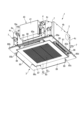
- FIG. 1 is a perspective view of an indoor unit of a ceiling-embedded air conditioner.
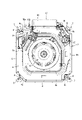
- FIG. 2 is a plan view showing a state in which a drain pan and a bell mouth are incorporated in the housing of the unit body.
- FIG. 3 is a plan view showing a state in which the drain pan and bell mouth are removed from the housing of the unit main body.
- FIG. 4 is a cross-sectional view along line A2-A2 of FIG.
- FIG. 5 is a cross-sectional view schematically showing the internal structure of a structure that defines the shape of at least some of the constituent elements that constitute the indoor unit according to the first embodiment.
- FIG. 6 is a cross-sectional view schematically showing the internal structure of a structure that defines the shape of at least some of the constituent elements that constitute the indoor unit according to the second embodiment.
- FIG. 1 is a perspective view of an indoor unit of a ceiling-embedded air conditioner.
- FIG. 2 is a plan view showing a state in which a drain pan and a bell mouth are incorporated in a housing of a unit main body, which will be described later.
- FIG. 3 is a plan view showing a state in which a drain pan and a bell mouth are removed from a housing of a unit main body, which will be described later.
- FIG. 4 is a cross-sectional view along line A2-A2 of FIG.
- an indoor unit 1 of an air conditioner includes, as main elements, a unit body 2 installed above the ceiling and a panel attached to the lower end of the unit body 2 (hereinafter referred to as a ceiling panel). 3.
- the unit main body 2 has a housing 4 .
- the housing 4 is a box-shaped element that opens downward, and is suspended from beams in the ceiling via, for example, four hanging bolts (not shown).
- the housing 4 includes a top plate portion 4a and side portions 4b.
- the side surface portion 4b continues in the circumferential direction of the housing 4 and has four outer peripheral corner portions 4c.
- the inner surfaces of the top plate portion 4a and the side portion 4b are covered with a heat insulating material 5 made of polystyrene foam, for example.
- the heat insulating material 5 defines an opening 6 at the lower end of the housing 4 .
- a hanging metal fitting 7 is fixed to the outer peripheral corner portion 4 c of the housing 4 .
- the hanging metal fittings 7 horizontally protrude toward the four sides of the housing 4 , and the hanging metal fittings 7 are connected to the lower ends of the hanging bolts.
- brackets 8 are fixed to the housing 4 .
- the bracket 8 is positioned at the lower end of the outer peripheral corner 4c of the housing 4 so as to be positioned directly below the hanging metal fitting 7. As shown in FIG.
- the brackets 8 horizontally protrude toward the four sides of the housing 4 .
- the air blower 10 draws in air in a space to be air-conditioned, that is, indoor air, and blows out the air heat-exchanged by the heat exchanger 11 indoors.
- a so-called centrifugal fan is used that draws in air from the axial direction and blows it out in the circumferential direction.
- the blower 10 has a fan driving section 10a and a fan section 10b.
- the fan driving section 10a is, for example, a motor, fixed to the top plate section 4a of the housing 4 via the heat insulating material 5, and rotates the rotating shaft 10c.
- the fan section 10b has a plurality of blades 10d arranged at a predetermined pitch in the circumferential direction, and is concentrically attached to the tip of the rotating shaft 10c to rotate together with the rotating shaft 10c. Since the upper end of the fan portion 10b is covered with the top plate portion 4a of the housing 4, the lower end of the fan portion 10b serves as the suction side.
- the heat exchanger 11 performs heat exchange between the space to be air-conditioned, that is, the air in the room and the refrigerant, and air-conditions the room.
- the heat exchanger 11 is erected inside the housing 4 so as to surround the blowing side of the blower 10 .
- the heat exchanger 11 includes a plurality of radiation fins 12 and a plurality of heat transfer tubes 13 through which refrigerant flows.
- the radiating fins 12 are elongated plates extending in the height direction of the housing 4 and are arranged side by side in the circumferential direction of the housing 4 at intervals.
- the heat transfer tubes 13 are arranged at intervals in the height direction and the lateral direction of the housing 4, and are connected in series to form a plurality of flow paths (paths). Furthermore, the heat transfer tube 13 is thermally connected to the heat radiation fins 12 by passing through the heat radiation fins 12 .
- the refrigerant pipes 14 connected to the heat exchanger 11 are concentrated in the space between one outer peripheral corner 4c of the housing 4 and the heat exchanger 11.
- the refrigerant pipe 14 is connected to a pair of connection ports 16a and 16b.
- the connection ports 16a and 16b protrude from one outer peripheral corner 4c of the housing 4 to the outside of the housing 4, and are connected to the outdoor unit of the air conditioner via a liquid pipe and a gas pipe.
- a drain pump 17 is housed inside the housing 4 .
- the drain pump 17 is an element for discharging condensed water produced by the heat exchange action of the heat exchanger 11 to the outside of the unit main body 2 when the indoor unit 1 is in cooling operation.
- the drain pump 17 is arranged at the lower end of the housing 4 near another outer peripheral corner 4c adjacent to the outer peripheral corner 4c provided with the connection ports 16a and 16b.
- a drain pipe 18 connected to the drain pump 17 is routed above the drain pump 17 through the interior of the housing 4 .
- the drain pan 20 is an element for receiving condensed water produced by the heat exchange action of the heat exchanger 11 .
- the drain pan 20 includes a heat-insulating body 21 and a sheet material 22 integrally laminated on the surface of the body 21 .
- the main body 21 is an element that defines the shape of the drain pan 20 .
- the sheet material 22 is made of a synthetic resin material having a thickness of several millimeters, for example, and has higher rigidity than the main body 21 . ABS resin, for example, is used as the synthetic resin material forming the sheet material 22 .
- the drain pan 20 is configured, for example, in a square frame shape corresponding to the heat exchanger 11 and is fitted inside the opening 6 defined by the heat insulating material 5 of the housing 4 .
- the drain pan 20 has a circular bell mouth mounting hole 23 positioned directly below the suction side of the blower 10 and a peripheral edge portion 24 surrounding the bell mouth mounting hole 23 .
- a peripheral portion 24 of the drain pan 20 is fitted inside the opening 6 of the housing 4 .
- a peripheral edge portion 24 of the drain pan 20 is formed with four notch portions 26 and a concave portion 27 into which the lower end portion of the heat exchanger 11 is inserted.
- the notch 26 has an elongated shape extending along the four sides of the peripheral edge 24 of the drain pan 20 .
- the notches 26 adjacent in the circumferential direction of the drain pan 20 are kept in a positional relationship such that they are perpendicular to each other. Since the peripheral edge portion 24 of the drain pan 20 is fitted inside the opening portion 6 defined by the heat insulating material 5 , the area surrounded by the notch portion 26 and the heat insulating material 5 is filled with the air that has passed through the heat exchanger 11 . It constitutes a plurality of communication ports 28 to be guided.
- the recessed portion 27 is a groove-like element continuous in the circumferential direction of the drain pan 20 and positioned inside the drain pan 20 relative to the notch portion 26 .
- the recessed portion 27 is defined by an inner peripheral wall 29a, an outer peripheral wall 29b and a bottom wall 29c.
- the inner peripheral wall 29a is erected from the bottom wall 29c so as to surround the bell mouth mounting hole 23.
- the inner peripheral wall 29 a can be rephrased as a partition wall interposed between the bell mouth mounting hole 23 and the recessed portion 27 .
- a bulging portion 31 that rises toward the lower end of the heat exchanger 11 is formed in the central portion of the bottom wall 29c.
- the bulging portion 31 is formed continuously in the circumferential direction of the drain pan 20 along the lower end of the heat exchanger 11 .
- a cushion material 32 that receives the lower end of the heat exchanger 11 is laminated on the upper surface of the bulging portion 31 .
- Such a drain pan 20 is detachably supported at the lower end of the housing 4 via four drain pan fixing fittings 38 as shown in FIG.
- the drain pan fixture 38 is screwed to the lower surface of the bracket 8 .
- the drain pan fixing metal fittings 38 horizontally protrude from the outer peripheral corners 4c of the housing 4 toward the four corners of the drain pan 20, and the corners of the drain pan 20 are placed on the drain pan fixing metal fittings 38. .
- the drain pan 20 is held at the lower end of the housing 4 so as not to drop out of the opening 6 of the housing 4 .
- an electrical unit 40 is supported on the front surface of the side portion 4b of the housing 4.
- the electrical unit 40 includes an electrical component box 41 exposed outside the housing 4 and a control board 42 housed in the electrical component box 41 .
- the control board 42 has various electrical components 43 such as a wiring board on which a plurality of IC chips are mounted, a reactor, and a terminal block.
- the control board 42 is electrically connected to the blower 10, the heat exchanger 11, the drain pump 17 and the like via a plurality of lead wires.
- a bell mouth 53 is detachably fitted into the bell mouth mounting hole 23 of the drain pan 20 .
- the bell mouth 53 is an element for straightening the flow of air sucked by the blower 10 .
- the bell mouth 53 includes a bell mouth body 54 having a trumpet-like shape that expands in diameter downward, and a bell mouth body 54 that extends radially outward from the lower end of the bell mouth body 54 that defines the maximum diameter of the bell mouth body 54 . and a flange portion 55 extending horizontally.
- the flange portion 55 is formed continuously in the circumferential direction of the bellmouth main body 54 . Further, an outer peripheral wall 56 is formed at the tip of the flange portion 55 so as to be bent downward at a right angle.
- the ceiling panel 3 of the indoor unit 1 is arranged along the ceiling (not shown) of the air-conditioned space, and covers the opening 6 at the lower end of the housing 4 from the indoor side.
- the ceiling panel 3 includes a grille (hereinafter referred to as intake grille) 80 and a frame 81 .
- the intake grille 80 is located in the central part of the ceiling panel 3, is rotatably supported by the frame 81, and is an element that shields an intake port (a working opening 87, which will be described later) that draws indoor air into the housing 4. be.
- the intake grille 80 includes a square-shaped outer frame portion 82 and a lattice portion 83 surrounded by the outer frame portion 82 .
- the grid portion 83 is positioned directly below the bell mouth 53 and has a removable filter (not shown).
- the frame body 81 of the ceiling panel 3 is, for example, a square-shaped element surrounding the intake grille 80. 86d.
- the first to fourth side portions 85a, 85b, 85c, 85d extend along the outer peripheral edge of the outer frame portion 82 of the intake grille 80, respectively.
- the corner portions 86a, 86b, 86c, and 86d are positioned at the four corners of the ceiling panel 3, and integrally extend between the first to fourth side portions 85a, 85b, 85c, and 85d adjacent to each other in the circumferential direction of the frame 81.
- connected to A rectangular area surrounded by inner peripheral edges of the first to fourth sides 85a, 85b, 85c, 85d defines a working opening 87.
- the work opening 87 is an opening portion for exposing the inside of the housing 4 to the room, for example, for cleaning and maintenance of the blower 10 and the heat exchanger 11 easily. Further, the work opening 87 corresponds to a suction port for sucking indoor air into the housing 4 .
- the ceiling panel 3 is detachably connected to the bracket 8 of the housing 4 at four corners 86a, 86b, 86c, 86d of the frame 81. Thereby, the lower end of the unit body 2 including the drain pan 20 and the bell mouth 53 is covered with the ceiling panel 3 .
- the ceiling panel 3 has four outlets 88 for blowing out the air heat-exchanged by the heat exchanger 11 into the room.
- the air outlets 88 are formed in the first to fourth side portions 85 a , 85 b , 85 c and 85 d of the frame 81 so as to face the four cutouts 26 of the drain pan 20 .
- louvers 89 are rotatably supported on the frame 81 of the ceiling panel 3 .
- the louver 89 is an element that changes the blowing direction of the air blown into the room from the blowing port 88, and is formed in a flat elongated plate shape.
- the louver 89 is rotatable between a closed position for closing the outlet 88 and an open position for opening the outlet 88 .
- the louver 89 becomes horizontal and completely covers the first to fourth sides 85a, 85b, 85c and 85d of the frame 81. .
- one side of the outer frame portion 82 is selectively rotatably connected to any one of the first to fourth side portions 85a, 85b, 85c, and 85d of the frame body 81. be. Therefore, the suction grille 80 is rotatable between the first position for closing the work opening and the second position for opening the work opening. Furthermore, the suction grille 80 can be removed from the frame body 81 in a state where the suction grille 80 is rotated to the second position.
- At least some of the components have shapes defined by the following structures. In other words, such a component is shaped by said structure.
- FIG. 5 is a cross-sectional view schematically showing the internal structure of the structure of some of these constituent elements.
- the structure 90 shown in FIG. 5 defines the shape of the housing 4 .
- the structure 90 of the housing 4 has an inner layer portion 90a and an outer layer portion 90b.
- the inner layer portion 90 a is a portion of the structure 90 that is not exposed to the outside, and simply corresponds to the inside of the structure 90 .
- the outer layer portion 90b is arranged adjacent to the inner layer portion 90a, is a portion of the structure 90 exposed to the outside, and simply corresponds to the surface portion of the structure 90. As shown in FIG. That is, the outer layer portion 90b entirely covers the inner layer portion 90a.
- FIG. 5 schematically shows an inner layer portion 90a and an outer layer portion 90b in a portion of the structure 90. In the illustrated example, the outer layer portions 90b are arranged in pairs with the inner layer portion 90a interposed therebetween. ing.
- the structure 90 having the inner layer portion 90a and the outer layer portion 90b is composed of a mixture of the first portion 91 and the second portion 92.
- the first portion 91 has a plurality of voids 93 in each of the inner layer portion 90a and the outer layer portion 90b.
- the second portion 92 has a plurality of voids 93 in each of the inner layer portion 90a and the outer layer portion 90b.
- the void 93 is a void with respect to the meat (solid portion) 94 of the inner layer portion 90a and the outer layer portion 90b, that is, a region where the meat 94 does not exist.
- the void 93 is a bubble whose interior is filled with air.
- the voids 93 of the outer layer portion 90 b are partially open to the outside and correspond to depressions in the surface portion of the structure 90 .
- the sizes and shapes of the plurality of voids 93 are all the same, but they may be different.
- the arrangement of the plurality of voids 93 may be regular or irregular.
- the plurality of voids 93 in the first portion 91 are regularly arranged, and the voids 93 in the second portion 92 are irregularly arranged.
- Some of the voids 93 may be substantially vacuum or filled with liquid. Alternatively, the interior of the void 93 may be filled with a mixture of air and liquid.
- the structural body 90 is formed by foaming a material obtained by adding a reinforcing material to a synthetic resin base material, for example, in the process of injection molding.
- the reinforcing material reinforces the wall portion 95 that partitions the air bubble that is the void 93 , in other words, the region surrounding the void 93 in the solid portion 94 .
- the reinforcing material may be ultrafine fibers or the like. Since the walls 95 of the voids 93 are reinforced by adding the reinforcing material, breakage of air bubbles during molding is suppressed. Therefore, for example, finer voids 93 can be formed, and the existence density (expansion ratio) of the voids 93 can be increased. In addition, the strength (rigidity) of the structure 90 is increased by reinforcing the wall portion 95 .
- the first portion 91 and the second portion 92 have different existence densities of the voids 93 per the same volume. Specifically, as shown in FIG. 5, the existence density of voids 93 is lower in the second portion 92 than in the first portion 91 per the same volume. In other words, the second portion 92 has the voids 93 with a lower existence density of the voids 93 per the same volume than the first portion 91 .
- the first portion 91 is a region with dense voids 93 (dense void portion)
- the second portion 92 is a region with sparse voids 93 (sparse void portion).
- the existence density of voids 93 can be understood as the number of voids 93 per predetermined volume.
- the ratio of the existence densities of the voids 93 in the first portion 91 and the second portion 92 per the same volume can be expressed as the ratio of the number of voids 93 in these portions 91 and 92 .
- the first part 91 and the second part 92 are mixedly arranged in each part of the structure 90 , that is, the housing 4 .
- the second portion 92 is arranged at a location on the housing 4 that receives a larger external force than the location where the first portion 91 is arranged.
- the second portion 92 is arranged at a specific location on the housing 4 where a relatively large external force acts.
- the first portion 91 is arranged at a location other than the specific location on the housing 4 .
- the specific locations are, for example, locations where the heat exchanger 11 is fixed to the housing 4 shown in FIG.
- the fixing portions 4d and 4e of the top plate portion 4a correspond to the specific portion.
- the fixed portion 4 d is positioned continuously near the outer periphery of the top plate portion 4 a corresponding to the arrangement of the heat exchangers 11 .
- the external force acting on the fixed portion 4d is, for example, the force applied by the weight of the heat exchanger 11 itself.
- the fixing portion 4e is positioned near the center of the top plate portion 4a corresponding to the arrangement of the fan driving portion 10a.
- the external force acting on the fixed portion 4e is, for example, the force applied by the dead weight of the air blower 10 including the fan drive portion 10a and the vibration of the fan drive portion 10a when it is driven. That is, external forces such as the force due to the weight of the heat exchanger 11 and the air blower 10 and the force due to the vibration of the fan driving portion 10a when driving are directly applied to the fixed portions 4d and 4e. Therefore, the influence of the external force on the fixed portions 4d and 4e is relatively large compared to the locations other than the specific locations.
- the location other than the specific location is, for example, a location other than the location where the heat exchanger 11 is fixed to the housing 4 shown in FIG. be.
- portions other than the fixed portions 4d and 4e of the top plate portion 4a non-fixed portion indicated by reference numeral 4f in FIG. 4
- the side portion 4b and the outer peripheral corner portion 4c (see FIGS. 1 to 3) are specified. It corresponds to a place other than a place.
- the force applied by the weight of the heat exchanger 11 and the air blower 10, for example, and the force applied by the vibration of the fan drive unit 10a during driving are directly applied to the non-fixed portion 4f, unlike the fixed portions 4d and 4e. not loaded. Therefore, the influence of the external force on the non-fixed portion 4f, the side surface portion 4b, and the outer peripheral corner portion 4c is relatively small compared to the fixed portions 4d and 4e.
- the fixed portions 4d and 4e of the housing 4, to which a relatively large external force is applied are defined as areas with dense voids 93 (dense void portions), and a relatively small external force is applied.
- the non-fixed portion 4f, the side surface portion 4b, and the outer peripheral corner portion 4c can be used as regions where the gaps 93 are sparse (sparse gap portions). That is, the weight of the housing 4 can be reduced by reducing the solid portion 94 by the space 93 while maintaining the strength (rigidity) against external force.
- the indoor unit 1 is installed in a high place such as a ceiling or a space above the ceiling, it is possible to shorten the work time and improve the work efficiency because the housing 4 is lightweight. , it is possible to improve workability.
- components other than the housing 4 of the indoor unit 1, such as the drain pan 20, the bell mouth 53, the panel 3, the grille 80, and the louver 89, are subjected to an external force acting on the fixed portions 4d and 4e of the housing 4. has no effect. Therefore, among the constituent elements other than the housing 4, some or all of the constituent elements have the same shape as the first portion (air gap dense portion) 91 arranged in the non-fixed portion 4f of the housing 4. It may be defined by a structure having a similar void 93 .
- the strength (rigidity) of the drain pan 20, the bell mouth 53, the panel 3, the grille 80, the louver 89, and the like can be maintained, and the weight can be reduced. Therefore, for example, maintenance of these components can be easily performed by the weight reduction. As a result, it is possible to shorten the working time, improve the working efficiency, and improve the workability.
- the first portion 91 and the second portion 92 as in the example shown in FIG. Each exists independently. However, these voids may communicate with each other between the inner layer portion 100a and the outer layer portion 100b, as shown in FIG.
- a form in which the gaps communicate with each other in this way will be described as a second embodiment.
- the basic configuration of the indoor unit of the air conditioner according to the second embodiment is the same as that of the indoor unit 1 (FIGS. 1 to 4) according to the first embodiment. Therefore, the description of the basic configuration of the indoor unit will be omitted or simplified below, and the differences from the first embodiment, which are features of the second embodiment, will be described in detail. At that time, the same reference numerals are used for the same or similar components as in the first embodiment, and the description is omitted or simplified.
- FIG. 6 is a cross-sectional view schematically showing the internal structure of the structure 100 of at least some of the various components that make up the indoor unit 1.
- the structure 100 for example, the housing 4, the drain pan 20, the bell mouth 53, the panel 3, the grille 80, the louver 89, etc. are applicable.
- the structure 100 has an inner layer portion 100a and an outer layer portion 100b, like the structure 90 (FIG. 5).
- the inner layer portion 100 a is a portion of the structure 100 that is not exposed to the outside, and simply corresponds to the inside of the structure 100 .
- the outer layer portion 100b is arranged adjacent to the inner layer portion 100a and is a portion of the structure 100 that is exposed to the outside.
- the structure 100 is composed of a mixture of the first portion 91 and the second portion 92, similarly to the structure 90. As shown in FIG.
- the plurality of voids 96 of the structure 100 communicate with each other between the inner layer portion 100a and the outer layer portion 100b.
- the void 96 is a void with respect to the meat (solid portion) 97, that is, a region where the meat 94 does not exist, and is, for example, a bubble whose interior is filled with air.
- the air bubbles which are the plurality of voids 96 , communicate with each other to form aggregates (hereinafter referred to as void groups) 98 .
- the gap group 98 is formed by continuous wall portions 99 that partition the plurality of air bubbles that are the gaps 96 , that is, regions surrounding the plurality of gaps 96 in the solid portion 97 .
- the void group 98 is configured as a space larger than each void 96 partitioned from the solid portion 97 by the plurality of wall portions 99, that is, as a plurality of continuous air bubbles.
- the gaps 96 of the outer layer portion 100 b are partly open to the outside and serve as communication ports 98 a to the gap group 98 on the surface of the structure 100 .
- the communication port 98a is an inlet leading to a plurality of voids 96 forming the void group 98, that is, a plurality of continuous air bubbles. That is, in the example shown in FIG. 6, a plurality of gaps 96 communicate from one outer layer portion 100b through the inner layer portion 100a to the other outer layer portion 100b.
- the void group 98 is in a state in which a plurality of voids 96 communicate from both outer layer portions 100b to the inner layer portions 100a.
- structure 100 is in a state in which the wall portions 99 of the voids 96 are exposed to the outside through the communication ports 98a in the outer layer portion 100b and the inner layer portion 100a. Therefore, structure 100 has an expanded area exposed to the outside compared to structure 90 (FIG. 5).
- FIG. 6 shows the form of voids 96 in the first portion (dense void portion) 91 .
- the shape of the voids 96 in the second portion (sparse void portion) 92 is the same as in the first portion 91 except that the existence density of the voids 96 is low. It has a form that communicates with each other.
- the following effects can be achieved while reducing the weight of the structure 100 . That is, moisture and water can flow from the outer layer portion 100b to the inner layer portion 100a through the void groups 98 and be absorbed. In addition, moisture and water absorbed in the gap group 98 can be transpired through the gap 96 of the outer layer portion 100b, that is, through the communication port 98a to the gap group 98.
- FIG. 1 A block diagram illustrating an void groups 98 in this way.
- the condensed water can be appropriately stored in the gap group 98 and can be appropriately evaporated. can be done.
- leakage of condensed water in the indoor unit 1 can be suppressed, and the air conditioning capacity can be improved. For example, it is possible to suppress the occurrence of mold due to dew condensation on the louver 89 .
- the structure 100 since the area exposed to the outside is expanded as compared with the structure 90 (FIG. 5), it can be exposed to not only moisture and water, but also odors, harmful substances, and dirt contained in the indoor air. etc. can also be adsorbed to the gap group 98 . Therefore, in addition to reducing the weight of the structure 100, for example, it is possible to enhance the indoor air cleaning effect and keep the air quality clean.
- the structure 100 is formed by, for example, foaming a material obtained by adding a reinforcing material to a synthetic resin serving as a base material in the process of injection molding.
- the base material of the structure 100 is made of a material that has a high affinity for water. For example, if the affinity of the base material for water is higher than that of the components of the indoor unit 1 other than the structure 100 having the void groups 98, that is, the base material of the structure that defines the shape of the component. good.
- the material included in the base material of the structure 100 is a material having a hydrophilic functional group such as a hydroxyl group (--OH group) or an amino group (--NH 3 ), specifically diatomaceous earth having such a functional group.
- the structure 100 may be formed by foaming a material obtained by adding a reinforcing material to a synthetic resin as a base material, for example, in the process of injection molding.
- the reinforcing material is, for example, ultrafine fibers, and reinforces the wall portion 99 that partitions the air bubbles that are the voids 96 , in other words, the region surrounding the void group 98 in the solid portion 97 . Since the walls 99 of the voids 96 are reinforced by adding the reinforcing material, the breakage of air bubbles during molding is suppressed, as in the first embodiment.
- Hydrophilic treatment such as plasma treatment may be applied to the surface of the structure 100 after molding.
- an organic material may be applied as the material included in the base material of the structure 100. It is thought that many of the causative agents of odors, harmful substances, and dirt contained in indoor air are organic substances. For this reason, these causative substances have good compatibility with, for example, carbon-based organic molecules such as activated charcoal, and are easily combined with them. Therefore, by applying an organic material as the material of the structure 100, it becomes easier to adsorb odors, harmful substances, dirt, and the like contained in indoor air. As a result, it is possible to further enhance the indoor air cleaning effect and keep the air quality cleaner.
- the bell mouth 53, the panel 3, the grille 80, the louver 89, etc. absorb odors, harmful substances, dirt, etc. contained in the indoor air, thereby enhancing the indoor air cleaning effect and improving the air quality. can keep.
- these parts are lighter than before, it becomes possible to perform operations such as detachment and replacement more easily. As a result, it is possible to improve the indoor air cleaning effect and air quality over a long period of time.
- SYMBOLS 1 Indoor unit of an air conditioner, 2... Unit main body, 3... Panel (ceiling panel), 4... Housing, 4a... Top plate part, 4b... Side part, 4c... Peripheral corner part, 4d, 4e... Fixed part , 4f... non-fixed part, 6... opening, 10... fan, 10a... fan driving part, 10b... fan part, 10c... rotating shaft, 10d... blade, 11... heat exchanger, 20... drain pan, 21... main body, 22... Sheet material 23... Bell mouth mounting hole 53... Bell mouth 54... Bell mouth main body 55... Flange part 80... Grill (suction grill) 81... Frame body 82... Outer frame part 83...
- Lattice Portion 87
- Working opening (suction port) 88
- Air outlet 89
- Louver 90 100 Structure 90a, 100a Inner layer portion 90b, 100b Outer layer portion 91 First portion (gap dense part), 92... second part (sparse gap part), 93, 96... gaps, 94, 97... meat (solid part), 95, 99... wall parts, 98... gap group, 98a... communication port.
Landscapes
- Engineering & Computer Science (AREA)
- Chemical & Material Sciences (AREA)
- Combustion & Propulsion (AREA)
- Mechanical Engineering (AREA)
- General Engineering & Computer Science (AREA)
- Air Filters, Heat-Exchange Apparatuses, And Housings Of Air-Conditioning Units (AREA)
Priority Applications (2)
| Application Number | Priority Date | Filing Date | Title |
|---|---|---|---|
| CN202280034055.7A CN117295917A (zh) | 2021-09-24 | 2022-09-02 | 空调机的室内单元 |
| JP2023549447A JP7608628B2 (ja) | 2021-09-24 | 2022-09-02 | 空気調和機の室内ユニット |
Applications Claiming Priority (2)
| Application Number | Priority Date | Filing Date | Title |
|---|---|---|---|
| JP2021155266 | 2021-09-24 | ||
| JP2021-155266 | 2021-09-24 |
Publications (1)
| Publication Number | Publication Date |
|---|---|
| WO2023047919A1 true WO2023047919A1 (ja) | 2023-03-30 |
Family
ID=85720558
Family Applications (1)
| Application Number | Title | Priority Date | Filing Date |
|---|---|---|---|
| PCT/JP2022/033089 Ceased WO2023047919A1 (ja) | 2021-09-24 | 2022-09-02 | 空気調和機の室内ユニット |
Country Status (3)
| Country | Link |
|---|---|
| JP (1) | JP7608628B2 (https=) |
| CN (1) | CN117295917A (https=) |
| WO (1) | WO2023047919A1 (https=) |
Citations (6)
| Publication number | Priority date | Publication date | Assignee | Title |
|---|---|---|---|---|
| JPH09170775A (ja) * | 1995-12-20 | 1997-06-30 | Toshiba Corp | 天井埋込み形空気調和機 |
| JPH10311551A (ja) * | 1997-05-14 | 1998-11-24 | Matsushita Seiko Co Ltd | 空気調和機 |
| JP2008202860A (ja) * | 2007-02-20 | 2008-09-04 | Hitachi Appliances Inc | 空気調和機の室内機、空気調和機、及び空気調和機の室内機のドレン水処理方法 |
| JP2011185584A (ja) * | 2010-03-11 | 2011-09-22 | Mitsubishi Electric Corp | 空気調和機の室内機 |
| WO2015181870A1 (ja) * | 2014-05-26 | 2015-12-03 | 日産自動車株式会社 | 複合材料成形体及びその製造方法 |
| JP2018141576A (ja) * | 2017-02-27 | 2018-09-13 | 東芝キヤリア株式会社 | 空気調和機 |
-
2022
- 2022-09-02 CN CN202280034055.7A patent/CN117295917A/zh active Pending
- 2022-09-02 JP JP2023549447A patent/JP7608628B2/ja active Active
- 2022-09-02 WO PCT/JP2022/033089 patent/WO2023047919A1/ja not_active Ceased
Patent Citations (6)
| Publication number | Priority date | Publication date | Assignee | Title |
|---|---|---|---|---|
| JPH09170775A (ja) * | 1995-12-20 | 1997-06-30 | Toshiba Corp | 天井埋込み形空気調和機 |
| JPH10311551A (ja) * | 1997-05-14 | 1998-11-24 | Matsushita Seiko Co Ltd | 空気調和機 |
| JP2008202860A (ja) * | 2007-02-20 | 2008-09-04 | Hitachi Appliances Inc | 空気調和機の室内機、空気調和機、及び空気調和機の室内機のドレン水処理方法 |
| JP2011185584A (ja) * | 2010-03-11 | 2011-09-22 | Mitsubishi Electric Corp | 空気調和機の室内機 |
| WO2015181870A1 (ja) * | 2014-05-26 | 2015-12-03 | 日産自動車株式会社 | 複合材料成形体及びその製造方法 |
| JP2018141576A (ja) * | 2017-02-27 | 2018-09-13 | 東芝キヤリア株式会社 | 空気調和機 |
Also Published As
| Publication number | Publication date |
|---|---|
| JP7608628B2 (ja) | 2025-01-06 |
| CN117295917A (zh) | 2023-12-26 |
| JPWO2023047919A1 (https=) | 2023-03-30 |
Similar Documents
| Publication | Publication Date | Title |
|---|---|---|
| JP5995107B2 (ja) | ビルトイン型空気調和装置 | |
| JP5832135B2 (ja) | 天井埋め込み型空気調和機 | |
| JPWO2017154081A1 (ja) | 空気調和機および送風装置 | |
| WO2013046899A1 (ja) | 空気調和装置 | |
| CN1148536C (zh) | 空气调节装置 | |
| WO2011007541A1 (ja) | 換気空調装置 | |
| JP5496697B2 (ja) | 空気調和装置の室外ユニット | |
| JP7258464B2 (ja) | 熱交換ユニット及びその製造方法 | |
| JP2018119720A (ja) | 天井埋込型空気調和機 | |
| JP5884069B2 (ja) | ビルトイン型空気調和装置 | |
| JP7608628B2 (ja) | 空気調和機の室内ユニット | |
| JP2011094817A (ja) | ダクト型空気調和機 | |
| JPH07158902A (ja) | 空気調和機の室外ユニット及びその組立方法 | |
| WO2006038352A1 (ja) | 空気調和装置 | |
| CN101031753A (zh) | 空调装置 | |
| JP2013213595A (ja) | ビルトイン型空気調和機 | |
| JP2006010178A (ja) | 空気調和機 | |
| WO2009133909A1 (ja) | 空気調和機の室内ユニット | |
| JP2018119714A (ja) | 天井埋込型空気調和機 | |
| JP7258053B2 (ja) | 底面パネル及び空気調和装置の室外機 | |
| JPH068411Y2 (ja) | 底面吸排型空気調和機 | |
| KR100474325B1 (ko) | 공기조화기의 실외유니트 | |
| JP7703283B2 (ja) | 空気調和機 | |
| JP2010117104A (ja) | 空調機 | |
| JPS6132269Y2 (https=) |
Legal Events
| Date | Code | Title | Description |
|---|---|---|---|
| 121 | Ep: the epo has been informed by wipo that ep was designated in this application |
Ref document number: 22872675 Country of ref document: EP Kind code of ref document: A1 |
|
| WWE | Wipo information: entry into national phase |
Ref document number: 2023549447 Country of ref document: JP |
|
| WWE | Wipo information: entry into national phase |
Ref document number: 202280034055.7 Country of ref document: CN |
|
| NENP | Non-entry into the national phase |
Ref country code: DE |
|
| 122 | Ep: pct application non-entry in european phase |
Ref document number: 22872675 Country of ref document: EP Kind code of ref document: A1 |