WO2023032799A1 - 非水電解質電池およびこれに用いる非水電解質 - Google Patents
非水電解質電池およびこれに用いる非水電解質 Download PDFInfo
- Publication number
- WO2023032799A1 WO2023032799A1 PCT/JP2022/031988 JP2022031988W WO2023032799A1 WO 2023032799 A1 WO2023032799 A1 WO 2023032799A1 JP 2022031988 W JP2022031988 W JP 2022031988W WO 2023032799 A1 WO2023032799 A1 WO 2023032799A1
- Authority
- WO
- WIPO (PCT)
- Prior art keywords
- aqueous electrolyte
- positive electrode
- group
- negative electrode
- mass
- Prior art date
Links
- 239000011255 nonaqueous electrolyte Substances 0.000 title claims abstract description 77
- -1 thiophene compound Chemical class 0.000 claims abstract description 59
- YTPLMLYBLZKORZ-UHFFFAOYSA-N Divinylene sulfide Natural products C=1C=CSC=1 YTPLMLYBLZKORZ-UHFFFAOYSA-N 0.000 claims abstract description 37
- 229930192474 thiophene Natural products 0.000 claims abstract description 31
- 125000006575 electron-withdrawing group Chemical group 0.000 claims abstract description 13
- IJGRMHOSHXDMSA-UHFFFAOYSA-N Atomic nitrogen Chemical compound N#N IJGRMHOSHXDMSA-UHFFFAOYSA-N 0.000 claims abstract description 12
- 239000003792 electrolyte Substances 0.000 claims abstract description 11
- 150000003839 salts Chemical class 0.000 claims abstract description 10
- QVGXLLKOCUKJST-UHFFFAOYSA-N atomic oxygen Chemical compound [O] QVGXLLKOCUKJST-UHFFFAOYSA-N 0.000 claims abstract description 8
- 229910052760 oxygen Inorganic materials 0.000 claims abstract description 8
- 239000001301 oxygen Substances 0.000 claims abstract description 8
- 229910052757 nitrogen Inorganic materials 0.000 claims abstract description 6
- 229910052751 metal Inorganic materials 0.000 claims description 23
- 239000007774 positive electrode material Substances 0.000 claims description 19
- 235000002639 sodium chloride Nutrition 0.000 claims description 11
- 229910052782 aluminium Inorganic materials 0.000 claims description 9
- 125000002915 carbonyl group Chemical group [*:2]C([*:1])=O 0.000 claims description 9
- 239000003125 aqueous solvent Substances 0.000 claims description 8
- 229910052744 lithium Inorganic materials 0.000 claims description 8
- VAUMDUIUEPIGHM-UHFFFAOYSA-N 5-Methyl-2-thiophenecarboxaldehyde Chemical compound CC1=CC=C(C=O)S1 VAUMDUIUEPIGHM-UHFFFAOYSA-N 0.000 claims description 7
- 229910052723 transition metal Inorganic materials 0.000 claims description 7
- 229910052748 manganese Inorganic materials 0.000 claims description 6
- 239000002905 metal composite material Substances 0.000 claims description 6
- 150000003577 thiophenes Chemical class 0.000 claims description 6
- IQPQWNKOIGAROB-UHFFFAOYSA-N isocyanate group Chemical group [N-]=C=O IQPQWNKOIGAROB-UHFFFAOYSA-N 0.000 claims description 5
- 229910052759 nickel Inorganic materials 0.000 claims description 5
- 125000002560 nitrile group Chemical group 0.000 claims description 5
- FAPWRFPIFSIZLT-UHFFFAOYSA-M Sodium chloride Chemical group [Na+].[Cl-] FAPWRFPIFSIZLT-UHFFFAOYSA-M 0.000 claims description 4
- ZYXKKRLXNLXYBV-UHFFFAOYSA-N 2-(5-methylthiophen-2-yl)propanenitrile Chemical compound N#CC(C)C1=CC=C(C)S1 ZYXKKRLXNLXYBV-UHFFFAOYSA-N 0.000 claims description 2
- TYOUGUHTXIYXLR-UHFFFAOYSA-N 2-isocyanato-5-methylthiophene Chemical compound CC1=CC=C(N=C=O)S1 TYOUGUHTXIYXLR-UHFFFAOYSA-N 0.000 claims description 2
- NQWNJWZLWMCDOJ-UHFFFAOYSA-N 3,5-dimethylthiophene-2-carbaldehyde Chemical compound CC1=CC(C)=C(C=O)S1 NQWNJWZLWMCDOJ-UHFFFAOYSA-N 0.000 claims description 2
- XTNYBMGQLIRVPS-UHFFFAOYSA-N 5-cyclopropylthiophene-2-carbaldehyde Chemical compound S1C(C=O)=CC=C1C1CC1 XTNYBMGQLIRVPS-UHFFFAOYSA-N 0.000 claims description 2
- DNPWNXMZXPEZGI-UHFFFAOYSA-N 5-ethynylthiophene-2-carbonitrile Chemical compound C#CC1=CC=C(C#N)S1 DNPWNXMZXPEZGI-UHFFFAOYSA-N 0.000 claims description 2
- 239000002904 solvent Substances 0.000 abstract 1
- 229910021645 metal ion Inorganic materials 0.000 description 27
- 239000002131 composite material Substances 0.000 description 20
- 210000004027 cell Anatomy 0.000 description 19
- 239000000203 mixture Substances 0.000 description 18
- 239000000463 material Substances 0.000 description 15
- PXHVJJICTQNCMI-UHFFFAOYSA-N nickel Substances [Ni] PXHVJJICTQNCMI-UHFFFAOYSA-N 0.000 description 14
- 238000011156 evaluation Methods 0.000 description 13
- 239000002184 metal Substances 0.000 description 13
- OKTJSMMVPCPJKN-UHFFFAOYSA-N Carbon Chemical compound [C] OKTJSMMVPCPJKN-UHFFFAOYSA-N 0.000 description 12
- 239000002245 particle Substances 0.000 description 12
- 230000008021 deposition Effects 0.000 description 11
- 238000006243 chemical reaction Methods 0.000 description 9
- 230000000694 effects Effects 0.000 description 9
- 239000010408 film Substances 0.000 description 9
- 238000007789 sealing Methods 0.000 description 9
- 238000004090 dissolution Methods 0.000 description 8
- 239000011267 electrode slurry Substances 0.000 description 8
- 239000007773 negative electrode material Substances 0.000 description 8
- 230000009467 reduction Effects 0.000 description 8
- 229910001416 lithium ion Inorganic materials 0.000 description 7
- RYGMFSIKBFXOCR-UHFFFAOYSA-N Copper Chemical compound [Cu] RYGMFSIKBFXOCR-UHFFFAOYSA-N 0.000 description 6
- JPVYNHNXODAKFH-UHFFFAOYSA-N Cu2+ Chemical compound [Cu+2] JPVYNHNXODAKFH-UHFFFAOYSA-N 0.000 description 6
- HBBGRARXTFLTSG-UHFFFAOYSA-N Lithium ion Chemical compound [Li+] HBBGRARXTFLTSG-UHFFFAOYSA-N 0.000 description 6
- SECXISVLQFMRJM-UHFFFAOYSA-N N-Methylpyrrolidone Chemical compound CN1CCCC1=O SECXISVLQFMRJM-UHFFFAOYSA-N 0.000 description 6
- 239000011230 binding agent Substances 0.000 description 6
- 239000011248 coating agent Substances 0.000 description 6
- 238000000576 coating method Methods 0.000 description 6
- 239000010949 copper Substances 0.000 description 6
- 229910001431 copper ion Inorganic materials 0.000 description 6
- 239000008151 electrolyte solution Substances 0.000 description 6
- 229910002804 graphite Inorganic materials 0.000 description 6
- 239000010439 graphite Substances 0.000 description 6
- 239000012948 isocyanate Substances 0.000 description 6
- 238000001556 precipitation Methods 0.000 description 6
- 239000003575 carbonaceous material Substances 0.000 description 5
- 230000000052 comparative effect Effects 0.000 description 5
- 238000002360 preparation method Methods 0.000 description 5
- 239000002562 thickening agent Substances 0.000 description 5
- KMTRUDSVKNLOMY-UHFFFAOYSA-N Ethylene carbonate Chemical compound O=C1OCCO1 KMTRUDSVKNLOMY-UHFFFAOYSA-N 0.000 description 4
- WHXSMMKQMYFTQS-UHFFFAOYSA-N Lithium Chemical compound [Li] WHXSMMKQMYFTQS-UHFFFAOYSA-N 0.000 description 4
- 239000000654 additive Substances 0.000 description 4
- 239000002041 carbon nanotube Substances 0.000 description 4
- 229910021393 carbon nanotube Inorganic materials 0.000 description 4
- 229910052802 copper Inorganic materials 0.000 description 4
- 239000013078 crystal Substances 0.000 description 4
- 239000002612 dispersion medium Substances 0.000 description 4
- JBTWLSYIZRCDFO-UHFFFAOYSA-N ethyl methyl carbonate Chemical compound CCOC(=O)OC JBTWLSYIZRCDFO-UHFFFAOYSA-N 0.000 description 4
- 239000011888 foil Substances 0.000 description 4
- 239000005001 laminate film Substances 0.000 description 4
- 230000002829 reductive effect Effects 0.000 description 4
- 229920005989 resin Polymers 0.000 description 4
- 239000011347 resin Substances 0.000 description 4
- HNENEALJPWJWJY-UHFFFAOYSA-N 2,4-difluoro-1-isocyanatobenzene Chemical compound FC1=CC=C(N=C=O)C(F)=C1 HNENEALJPWJWJY-UHFFFAOYSA-N 0.000 description 3
- XEKOWRVHYACXOJ-UHFFFAOYSA-N Ethyl acetate Chemical compound CCOC(C)=O XEKOWRVHYACXOJ-UHFFFAOYSA-N 0.000 description 3
- XEEYBQQBJWHFJM-UHFFFAOYSA-N Iron Chemical compound [Fe] XEEYBQQBJWHFJM-UHFFFAOYSA-N 0.000 description 3
- 229910013870 LiPF 6 Inorganic materials 0.000 description 3
- XBDQKXXYIPTUBI-UHFFFAOYSA-M Propionate Chemical compound CCC([O-])=O XBDQKXXYIPTUBI-UHFFFAOYSA-M 0.000 description 3
- XAGFODPZIPBFFR-UHFFFAOYSA-N aluminium Chemical compound [Al] XAGFODPZIPBFFR-UHFFFAOYSA-N 0.000 description 3
- 150000001875 compounds Chemical class 0.000 description 3
- 230000007423 decrease Effects 0.000 description 3
- 125000000524 functional group Chemical group 0.000 description 3
- 238000002347 injection Methods 0.000 description 3
- 239000007924 injection Substances 0.000 description 3
- 239000011163 secondary particle Substances 0.000 description 3
- 229910052710 silicon Inorganic materials 0.000 description 3
- LIVNPJMFVYWSIS-UHFFFAOYSA-N silicon monoxide Chemical class [Si-]#[O+] LIVNPJMFVYWSIS-UHFFFAOYSA-N 0.000 description 3
- 230000006641 stabilisation Effects 0.000 description 3
- 238000011105 stabilization Methods 0.000 description 3
- 229910001220 stainless steel Inorganic materials 0.000 description 3
- 239000010935 stainless steel Substances 0.000 description 3
- 229920003048 styrene butadiene rubber Polymers 0.000 description 3
- OIFBSDVPJOWBCH-UHFFFAOYSA-N Diethyl carbonate Chemical compound CCOC(=O)OCC OIFBSDVPJOWBCH-UHFFFAOYSA-N 0.000 description 2
- 239000004698 Polyethylene Substances 0.000 description 2
- 239000002174 Styrene-butadiene Substances 0.000 description 2
- KXKVLQRXCPHEJC-UHFFFAOYSA-N acetic acid trimethyl ester Natural products COC(C)=O KXKVLQRXCPHEJC-UHFFFAOYSA-N 0.000 description 2
- 150000001642 boronic acid derivatives Chemical class 0.000 description 2
- 229910052791 calcium Inorganic materials 0.000 description 2
- 229910052799 carbon Inorganic materials 0.000 description 2
- 125000003178 carboxy group Chemical group [H]OC(*)=O 0.000 description 2
- 229920002678 cellulose Polymers 0.000 description 2
- 239000001913 cellulose Substances 0.000 description 2
- 150000005678 chain carbonates Chemical class 0.000 description 2
- 239000006258 conductive agent Substances 0.000 description 2
- 239000011889 copper foil Substances 0.000 description 2
- 150000005676 cyclic carbonates Chemical class 0.000 description 2
- 238000007599 discharging Methods 0.000 description 2
- 238000001035 drying Methods 0.000 description 2
- 238000002149 energy-dispersive X-ray emission spectroscopy Methods 0.000 description 2
- FKRCODPIKNYEAC-UHFFFAOYSA-N ethyl propionate Chemical compound CCOC(=O)CC FKRCODPIKNYEAC-UHFFFAOYSA-N 0.000 description 2
- GAEKPEKOJKCEMS-UHFFFAOYSA-N gamma-valerolactone Chemical compound CC1CCC(=O)O1 GAEKPEKOJKCEMS-UHFFFAOYSA-N 0.000 description 2
- 238000010438 heat treatment Methods 0.000 description 2
- 238000002354 inductively-coupled plasma atomic emission spectroscopy Methods 0.000 description 2
- 229910052742 iron Inorganic materials 0.000 description 2
- AMXOYNBUYSYVKV-UHFFFAOYSA-M lithium bromide Chemical compound [Li+].[Br-] AMXOYNBUYSYVKV-UHFFFAOYSA-M 0.000 description 2
- KWGKDLIKAYFUFQ-UHFFFAOYSA-M lithium chloride Chemical compound [Li+].[Cl-] KWGKDLIKAYFUFQ-UHFFFAOYSA-M 0.000 description 2
- 229910003002 lithium salt Inorganic materials 0.000 description 2
- 159000000002 lithium salts Chemical class 0.000 description 2
- 238000004519 manufacturing process Methods 0.000 description 2
- 238000000034 method Methods 0.000 description 2
- TZIHFWKZFHZASV-UHFFFAOYSA-N methyl formate Chemical compound COC=O TZIHFWKZFHZASV-UHFFFAOYSA-N 0.000 description 2
- 239000012046 mixed solvent Substances 0.000 description 2
- 238000012986 modification Methods 0.000 description 2
- 230000004048 modification Effects 0.000 description 2
- 229910052758 niobium Inorganic materials 0.000 description 2
- 229920000573 polyethylene Polymers 0.000 description 2
- 239000011164 primary particle Substances 0.000 description 2
- RUOJZAUFBMNUDX-UHFFFAOYSA-N propylene carbonate Chemical compound CC1COC(=O)O1 RUOJZAUFBMNUDX-UHFFFAOYSA-N 0.000 description 2
- 229910052814 silicon oxide Inorganic materials 0.000 description 2
- 239000002002 slurry Substances 0.000 description 2
- 229910052712 strontium Inorganic materials 0.000 description 2
- 230000001629 suppression Effects 0.000 description 2
- 125000003396 thiol group Chemical group [H]S* 0.000 description 2
- 239000010936 titanium Substances 0.000 description 2
- 229910052719 titanium Inorganic materials 0.000 description 2
- XLYOFNOQVPJJNP-UHFFFAOYSA-N water Substances O XLYOFNOQVPJJNP-UHFFFAOYSA-N 0.000 description 2
- VAYTZRYEBVHVLE-UHFFFAOYSA-N 1,3-dioxol-2-one Chemical compound O=C1OC=CO1 VAYTZRYEBVHVLE-UHFFFAOYSA-N 0.000 description 1
- GEWWCWZGHNIUBW-UHFFFAOYSA-N 1-(4-nitrophenyl)propan-2-one Chemical compound CC(=O)CC1=CC=C([N+]([O-])=O)C=C1 GEWWCWZGHNIUBW-UHFFFAOYSA-N 0.000 description 1
- UHOPWFKONJYLCF-UHFFFAOYSA-N 2-(2-sulfanylethyl)isoindole-1,3-dione Chemical compound C1=CC=C2C(=O)N(CCS)C(=O)C2=C1 UHOPWFKONJYLCF-UHFFFAOYSA-N 0.000 description 1
- BJWMSGRKJIOCNR-UHFFFAOYSA-N 4-ethenyl-1,3-dioxolan-2-one Chemical compound C=CC1COC(=O)O1 BJWMSGRKJIOCNR-UHFFFAOYSA-N 0.000 description 1
- SBLRHMKNNHXPHG-UHFFFAOYSA-N 4-fluoro-1,3-dioxolan-2-one Chemical compound FC1COC(=O)O1 SBLRHMKNNHXPHG-UHFFFAOYSA-N 0.000 description 1
- 229920000178 Acrylic resin Polymers 0.000 description 1
- 239000004925 Acrylic resin Substances 0.000 description 1
- 229910000838 Al alloy Inorganic materials 0.000 description 1
- FERIUCNNQQJTOY-UHFFFAOYSA-M Butyrate Chemical compound CCCC([O-])=O FERIUCNNQQJTOY-UHFFFAOYSA-M 0.000 description 1
- 229920000049 Carbon (fiber) Polymers 0.000 description 1
- 229920002134 Carboxymethyl cellulose Polymers 0.000 description 1
- 229910000881 Cu alloy Inorganic materials 0.000 description 1
- LFQSCWFLJHTTHZ-UHFFFAOYSA-N Ethanol Chemical compound CCO LFQSCWFLJHTTHZ-UHFFFAOYSA-N 0.000 description 1
- 229910000733 Li alloy Inorganic materials 0.000 description 1
- 229910010238 LiAlCl 4 Inorganic materials 0.000 description 1
- 229910015015 LiAsF 6 Inorganic materials 0.000 description 1
- 229910013063 LiBF 4 Inorganic materials 0.000 description 1
- 229910013684 LiClO 4 Inorganic materials 0.000 description 1
- 229910015746 LiNi0.88Co0.09Al0.03O2 Inorganic materials 0.000 description 1
- 229910012513 LiSbF 6 Inorganic materials 0.000 description 1
- RJUFJBKOKNCXHH-UHFFFAOYSA-N Methyl propionate Chemical compound CCC(=O)OC RJUFJBKOKNCXHH-UHFFFAOYSA-N 0.000 description 1
- 229910000990 Ni alloy Inorganic materials 0.000 description 1
- 239000002033 PVDF binder Substances 0.000 description 1
- 239000004743 Polypropylene Substances 0.000 description 1
- 229910000676 Si alloy Inorganic materials 0.000 description 1
- 229910004298 SiO 2 Inorganic materials 0.000 description 1
- XUIMIQQOPSSXEZ-UHFFFAOYSA-N Silicon Chemical compound [Si] XUIMIQQOPSSXEZ-UHFFFAOYSA-N 0.000 description 1
- RTAQQCXQSZGOHL-UHFFFAOYSA-N Titanium Chemical compound [Ti] RTAQQCXQSZGOHL-UHFFFAOYSA-N 0.000 description 1
- SYRDSFGUUQPYOB-UHFFFAOYSA-N [Li+].[Li+].[Li+].[O-]B([O-])[O-].FC(=O)C(F)=O Chemical compound [Li+].[Li+].[Li+].[O-]B([O-])[O-].FC(=O)C(F)=O SYRDSFGUUQPYOB-UHFFFAOYSA-N 0.000 description 1
- DPXJVFZANSGRMM-UHFFFAOYSA-N acetic acid;2,3,4,5,6-pentahydroxyhexanal;sodium Chemical compound [Na].CC(O)=O.OCC(O)C(O)C(O)C(O)C=O DPXJVFZANSGRMM-UHFFFAOYSA-N 0.000 description 1
- 230000000996 additive effect Effects 0.000 description 1
- 125000003172 aldehyde group Chemical group 0.000 description 1
- 125000003342 alkenyl group Chemical group 0.000 description 1
- 125000000217 alkyl group Chemical group 0.000 description 1
- 230000004075 alteration Effects 0.000 description 1
- 150000001450 anions Chemical class 0.000 description 1
- 229910021383 artificial graphite Inorganic materials 0.000 description 1
- 125000003118 aryl group Chemical group 0.000 description 1
- 125000004429 atom Chemical group 0.000 description 1
- 230000015572 biosynthetic process Effects 0.000 description 1
- 229910052796 boron Inorganic materials 0.000 description 1
- QHIWVLPBUQWDMQ-UHFFFAOYSA-N butyl prop-2-enoate;methyl 2-methylprop-2-enoate;prop-2-enoic acid Chemical compound OC(=O)C=C.COC(=O)C(C)=C.CCCCOC(=O)C=C QHIWVLPBUQWDMQ-UHFFFAOYSA-N 0.000 description 1
- 239000006229 carbon black Substances 0.000 description 1
- 239000004917 carbon fiber Substances 0.000 description 1
- 150000007942 carboxylates Chemical class 0.000 description 1
- 150000001733 carboxylic acid esters Chemical class 0.000 description 1
- 229920003086 cellulose ether Polymers 0.000 description 1
- 239000004020 conductor Substances 0.000 description 1
- 238000010276 construction Methods 0.000 description 1
- 125000001559 cyclopropyl group Chemical group [H]C1([H])C([H])([H])C1([H])* 0.000 description 1
- 238000000354 decomposition reaction Methods 0.000 description 1
- 238000009831 deintercalation Methods 0.000 description 1
- 210000001787 dendrite Anatomy 0.000 description 1
- 238000001514 detection method Methods 0.000 description 1
- IJKVHSBPTUYDLN-UHFFFAOYSA-N dihydroxy(oxo)silane Chemical compound O[Si](O)=O IJKVHSBPTUYDLN-UHFFFAOYSA-N 0.000 description 1
- IEJIGPNLZYLLBP-UHFFFAOYSA-N dimethyl carbonate Chemical compound COC(=O)OC IEJIGPNLZYLLBP-UHFFFAOYSA-N 0.000 description 1
- 238000009826 distribution Methods 0.000 description 1
- 230000002708 enhancing effect Effects 0.000 description 1
- 150000002148 esters Chemical group 0.000 description 1
- 229940093499 ethyl acetate Drugs 0.000 description 1
- 125000001495 ethyl group Chemical group [H]C([H])([H])C([H])([H])* 0.000 description 1
- WBJINCZRORDGAQ-UHFFFAOYSA-N formic acid ethyl ester Natural products CCOC=O WBJINCZRORDGAQ-UHFFFAOYSA-N 0.000 description 1
- 238000004817 gas chromatography Methods 0.000 description 1
- 229910021469 graphitizable carbon Inorganic materials 0.000 description 1
- 229910021385 hard carbon Inorganic materials 0.000 description 1
- 125000004435 hydrogen atom Chemical group [H]* 0.000 description 1
- 125000002887 hydroxy group Chemical group [H]O* 0.000 description 1
- 238000009413 insulation Methods 0.000 description 1
- 238000009830 intercalation Methods 0.000 description 1
- 230000010220 ion permeability Effects 0.000 description 1
- 150000002500 ions Chemical class 0.000 description 1
- 230000002427 irreversible effect Effects 0.000 description 1
- 125000000468 ketone group Chemical group 0.000 description 1
- 229910052745 lead Inorganic materials 0.000 description 1
- 239000001989 lithium alloy Substances 0.000 description 1
- DEUISMFZZMAAOJ-UHFFFAOYSA-N lithium dihydrogen borate oxalic acid Chemical compound B([O-])(O)O.C(C(=O)O)(=O)O.C(C(=O)O)(=O)O.[Li+] DEUISMFZZMAAOJ-UHFFFAOYSA-N 0.000 description 1
- HSZCZNFXUDYRKD-UHFFFAOYSA-M lithium iodide Inorganic materials [Li+].[I-] HSZCZNFXUDYRKD-UHFFFAOYSA-M 0.000 description 1
- QSZMZKBZAYQGRS-UHFFFAOYSA-N lithium;bis(trifluoromethylsulfonyl)azanide Chemical compound [Li+].FC(F)(F)S(=O)(=O)[N-]S(=O)(=O)C(F)(F)F QSZMZKBZAYQGRS-UHFFFAOYSA-N 0.000 description 1
- 229910052749 magnesium Inorganic materials 0.000 description 1
- 239000011159 matrix material Substances 0.000 description 1
- 150000002739 metals Chemical class 0.000 description 1
- 229920000609 methyl cellulose Polymers 0.000 description 1
- 125000002496 methyl group Chemical group [H]C([H])([H])* 0.000 description 1
- 229940017219 methyl propionate Drugs 0.000 description 1
- 239000001923 methylcellulose Substances 0.000 description 1
- 235000010981 methylcellulose Nutrition 0.000 description 1
- 238000010295 mobile communication Methods 0.000 description 1
- 229910052750 molybdenum Inorganic materials 0.000 description 1
- YKYONYBAUNKHLG-UHFFFAOYSA-N n-Propyl acetate Natural products CCCOC(C)=O YKYONYBAUNKHLG-UHFFFAOYSA-N 0.000 description 1
- 229910021382 natural graphite Inorganic materials 0.000 description 1
- 229910021470 non-graphitizable carbon Inorganic materials 0.000 description 1
- 239000004745 nonwoven fabric Substances 0.000 description 1
- 230000002093 peripheral effect Effects 0.000 description 1
- 230000000704 physical effect Effects 0.000 description 1
- 229920006122 polyamide resin Polymers 0.000 description 1
- 229920001721 polyimide Polymers 0.000 description 1
- 239000009719 polyimide resin Substances 0.000 description 1
- 229920000098 polyolefin Polymers 0.000 description 1
- 229920005672 polyolefin resin Polymers 0.000 description 1
- 229920001155 polypropylene Polymers 0.000 description 1
- 229920002981 polyvinylidene fluoride Polymers 0.000 description 1
- 229940090181 propyl acetate Drugs 0.000 description 1
- 238000006479 redox reaction Methods 0.000 description 1
- 239000000523 sample Substances 0.000 description 1
- 229910052706 scandium Inorganic materials 0.000 description 1
- 238000000790 scattering method Methods 0.000 description 1
- 239000010703 silicon Substances 0.000 description 1
- 150000003377 silicon compounds Chemical class 0.000 description 1
- 239000011734 sodium Substances 0.000 description 1
- 235000019812 sodium carboxymethyl cellulose Nutrition 0.000 description 1
- 229910021384 soft carbon Inorganic materials 0.000 description 1
- 230000000087 stabilizing effect Effects 0.000 description 1
- 239000010409 thin film Substances 0.000 description 1
- 229910052718 tin Inorganic materials 0.000 description 1
- 150000003624 transition metals Chemical class 0.000 description 1
- 238000013519 translation Methods 0.000 description 1
- 229910052721 tungsten Inorganic materials 0.000 description 1
- NQPDZGIKBAWPEJ-UHFFFAOYSA-N valeric acid Chemical compound CCCCC(O)=O NQPDZGIKBAWPEJ-UHFFFAOYSA-N 0.000 description 1
- 125000000391 vinyl group Chemical group [H]C([*])=C([H])[H] 0.000 description 1
- 229920002554 vinyl polymer Polymers 0.000 description 1
- 239000002759 woven fabric Substances 0.000 description 1
- 229910052727 yttrium Inorganic materials 0.000 description 1
- 229910052725 zinc Inorganic materials 0.000 description 1
- 229910052726 zirconium Inorganic materials 0.000 description 1
Images
Classifications
-
- H—ELECTRICITY
- H01—ELECTRIC ELEMENTS
- H01M—PROCESSES OR MEANS, e.g. BATTERIES, FOR THE DIRECT CONVERSION OF CHEMICAL ENERGY INTO ELECTRICAL ENERGY
- H01M10/00—Secondary cells; Manufacture thereof
- H01M10/05—Accumulators with non-aqueous electrolyte
- H01M10/052—Li-accumulators
-
- H—ELECTRICITY
- H01—ELECTRIC ELEMENTS
- H01M—PROCESSES OR MEANS, e.g. BATTERIES, FOR THE DIRECT CONVERSION OF CHEMICAL ENERGY INTO ELECTRICAL ENERGY
- H01M10/00—Secondary cells; Manufacture thereof
- H01M10/05—Accumulators with non-aqueous electrolyte
- H01M10/056—Accumulators with non-aqueous electrolyte characterised by the materials used as electrolytes, e.g. mixed inorganic/organic electrolytes
- H01M10/0564—Accumulators with non-aqueous electrolyte characterised by the materials used as electrolytes, e.g. mixed inorganic/organic electrolytes the electrolyte being constituted of organic materials only
- H01M10/0566—Liquid materials
- H01M10/0567—Liquid materials characterised by the additives
-
- H—ELECTRICITY
- H01—ELECTRIC ELEMENTS
- H01M—PROCESSES OR MEANS, e.g. BATTERIES, FOR THE DIRECT CONVERSION OF CHEMICAL ENERGY INTO ELECTRICAL ENERGY
- H01M4/00—Electrodes
- H01M4/02—Electrodes composed of, or comprising, active material
- H01M4/36—Selection of substances as active materials, active masses, active liquids
- H01M4/48—Selection of substances as active materials, active masses, active liquids of inorganic oxides or hydroxides
- H01M4/50—Selection of substances as active materials, active masses, active liquids of inorganic oxides or hydroxides of manganese
- H01M4/505—Selection of substances as active materials, active masses, active liquids of inorganic oxides or hydroxides of manganese of mixed oxides or hydroxides containing manganese for inserting or intercalating light metals, e.g. LiMn2O4 or LiMn2OxFy
-
- H—ELECTRICITY
- H01—ELECTRIC ELEMENTS
- H01M—PROCESSES OR MEANS, e.g. BATTERIES, FOR THE DIRECT CONVERSION OF CHEMICAL ENERGY INTO ELECTRICAL ENERGY
- H01M4/00—Electrodes
- H01M4/02—Electrodes composed of, or comprising, active material
- H01M4/36—Selection of substances as active materials, active masses, active liquids
- H01M4/48—Selection of substances as active materials, active masses, active liquids of inorganic oxides or hydroxides
- H01M4/52—Selection of substances as active materials, active masses, active liquids of inorganic oxides or hydroxides of nickel, cobalt or iron
- H01M4/525—Selection of substances as active materials, active masses, active liquids of inorganic oxides or hydroxides of nickel, cobalt or iron of mixed oxides or hydroxides containing iron, cobalt or nickel for inserting or intercalating light metals, e.g. LiNiO2, LiCoO2 or LiCoOxFy
-
- Y—GENERAL TAGGING OF NEW TECHNOLOGICAL DEVELOPMENTS; GENERAL TAGGING OF CROSS-SECTIONAL TECHNOLOGIES SPANNING OVER SEVERAL SECTIONS OF THE IPC; TECHNICAL SUBJECTS COVERED BY FORMER USPC CROSS-REFERENCE ART COLLECTIONS [XRACs] AND DIGESTS
- Y02—TECHNOLOGIES OR APPLICATIONS FOR MITIGATION OR ADAPTATION AGAINST CLIMATE CHANGE
- Y02E—REDUCTION OF GREENHOUSE GAS [GHG] EMISSIONS, RELATED TO ENERGY GENERATION, TRANSMISSION OR DISTRIBUTION
- Y02E60/00—Enabling technologies; Technologies with a potential or indirect contribution to GHG emissions mitigation
- Y02E60/10—Energy storage using batteries
Definitions
- the present disclosure mainly relates to nonaqueous electrolytes for nonaqueous electrolyte batteries.
- a non-aqueous electrolyte battery represented by a lithium-ion secondary battery includes a positive electrode, a negative electrode, and a non-aqueous electrolyte. If metal foreign matter such as copper or iron is present in a non-aqueous electrolyte battery that utilizes an electrochemical redox reaction, a dissolution/precipitation reaction of the metal foreign matter may occur and the voltage of the non-aqueous electrolyte battery may drop.
- Patent Document 1 by providing a compound containing one or more thiol groups in the molecule inside a unit cell of a battery, the compound containing a thiol group reacts with copper ions generated during operation of the battery, or forms copper ions. and prevent the formation of dendrites by reducing the copper ions on the negative electrode surface.
- Patent Document 2 discloses that a negative electrode active material containing at least one atom selected from the group consisting of Si, Sn and Pb is formed by using a non-aqueous electrolytic solution containing an isocyanate compound having at least one aromatic ring in the molecule. We propose to improve the cycle characteristics of the secondary battery using the material.
- Patent Document 1 Even if the method described in Patent Document 1 is used, the suppression of dissolution and precipitation of metallic foreign matter is insufficient. Further suppression of dissolution and deposition of metallic foreign matter is required.
- One aspect of the present disclosure includes a non-aqueous solvent, an electrolyte salt, and a thiophene compound having at least one electron-withdrawing group R containing oxygen or nitrogen, wherein the content of the thiophene compound is 0.01 mass % or more and 10% by mass or less of the nonaqueous electrolyte for nonaqueous electrolyte batteries.
- a nonaqueous electrolyte battery including a positive electrode containing a positive electrode active material, a separator, a negative electrode facing the positive electrode with the separator interposed therebetween, and the above nonaqueous electrolyte.
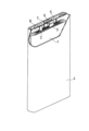
- FIG. 1 is a partially cutaway perspective view of a non-electrolyte battery according to an embodiment of the present disclosure
- the present disclosure encompasses a combination of matters described in two or more claims arbitrarily selected from the multiple claims described in the attached claims. In other words, as long as there is no technical contradiction, the matters described in two or more claims arbitrarily selected from the multiple claims described in the attached claims can be combined.
- a non-aqueous electrolyte for a non-aqueous electrolyte battery according to the present disclosure includes a non-aqueous solvent, an electrolyte salt, and a thiophene compound having at least one electron-withdrawing group R containing oxygen or nitrogen.
- the content of the thiophene compound with respect to the entire non-aqueous electrolyte is 0.01% by mass or more and 10% by mass or less.
- a non-aqueous electrolyte battery includes a positive electrode containing a positive electrode active material, a separator, a negative electrode facing the positive electrode via the separator, and the non-aqueous electrolyte.
- metal ions When the metal is exposed to the positive electrode potential, metal ions may be eluted from the metal into the non-aqueous electrolyte.
- metal ions may be eluted from the positive electrode active material.
- the positive electrode of a non-aqueous electrolyte battery contains a positive electrode active material, and the positive electrode active material has a high potential and contains a metal component (transition metal in many cases).
- Metal ions eluted into the non-aqueous electrolyte move from the positive electrode side to the negative electrode side and are deposited on the negative electrode side. As such a dissolution-precipitation reaction progresses, the voltage of the non-aqueous electrolyte battery decreases. In non-aqueous electrolyte batteries, it is important to suppress metal dissolution and deposition.
- the metal dissolution-precipitation reaction is remarkably suppressed, and the decrease in battery voltage is suppressed.
- the thiophene compound captures metal ions in the non-aqueous electrolyte at the structural site of the thiophene ring and suppresses the reduction deposition reaction of the metal ions in the negative electrode.
- the electron-withdrawing group R contained in the thiophene compound has the effect of enhancing the ability of the thiophene ring to trap metal ions, and the electron-withdrawing group R itself also traps metal ions in the non-aqueous electrolyte, It is believed that this has the effect of suppressing the reduction deposition reaction of metal ions in the negative electrode.
- the ability of the thiophene compound to trap metal ions is enhanced, or the thiophene compound has a plurality of different functional groups capable of trapping metal ions. is remarkably suppressed.
- metal ions can generally exist in a plurality of different ionic valences in non-aqueous electrolytes.
- copper ions can exist in two types of valences, Cu + and Cu 2+ , in a non-aqueous electrolyte, each of which has a different electron-accepting property.
- a compound having two or more different functional groups that are easily coordinated according to the valence of the metal ion can capture the metal ion with high efficiency.
- the electron-withdrawing group R contained in the thiophene compound can have coordinative bonding with metal ions. Electron withdrawing groups R include oxygen or nitrogen. The electron withdrawing group R may contain both oxygen and nitrogen. The electron-withdrawing group R includes at least one selected from the group consisting of carbonyl groups, nitrile groups, and isocyanate groups.
- the carbonyl group may constitute an aldehyde group in which one end of the carbonyl group is bonded to a hydrogen atom, may constitute a carboxy group in which one end of the carbonyl group is bonded to a hydroxyl group, or may be a ketone group. .
- a carboxy group may form an anion or a salt.
- a carbonyl group, a nitrile group, and an isocyanate group may be bonded to a thiophene ring. That is, the electron withdrawing group R may be attached directly to the thiophene ring.
- a carbonyl group may be an ester carbonyl group.
- the thiophene compound may further have an alkyl group (methyl group, ethyl group, cyclopropyl group, etc.), alkenyl group, or the like bonded to the thiophene ring.
- thiophene compounds are shown below. However, the thiophene compound is not limited to the following. Moreover, one type of thiophene compound may be used alone, or two or more types may be used in any combination.
- the thiophene ring of the thiophene compound may be hydrogenated (hydrogenated).
- Thiophene compounds having a carbonyl group include, for example, 5-methylthiophene-2-carbaldehyde, 3,5-dimethylthiophene-2-carbaldehyde, 5-cyclopropylthiophene-2-carbaldehyde, 2-((trimethylsilyl) methyl)tetrahydrothiophene-2-carbaldehyde, and the like.
- Thiophene compounds having a nitrile group include 5-ethynylthiophene-2-carbonitrile, 2-(5-methylthiophen-2-yl)propanenitrile, 4-(2-(5-hexylthiophen-2-yl)vinyl )-1,3,5-triazine-2-carbonitrile, and the like.
- Thiophene compounds having an isocyanate group include 2-isocyanato-5-methylthiophene, 2-isocyanato-5-(trifluoromethyl)thiophene, and the like.
- 5-methylthiophene-2-carbaldehyde can be preferably used because of its high compatibility with non-aqueous solvents.
- the structural formula of 5-methylthiophene-2-carbaldehyde is shown below.
- a nonaqueous electrolyte battery includes, for example, a positive electrode, a negative electrode, a nonaqueous electrolyte, and a separator as described below.
- Non-aqueous electrolyte contains a non-aqueous solvent, an electrolyte salt and a thiophene compound.
- a thiophene compound has an electron withdrawing group R as described above.
- the content of the thiophene compound with respect to the entire non-aqueous electrolyte is 0.01% by mass or more and 10% by mass or less, the effect of suppressing reduction deposition of metal ions can be sufficiently obtained.
- the content of the thiophene compound with respect to the entire non-aqueous electrolyte is preferably 0.1% by mass or more and 5% by mass or less in order to obtain an effect of suppressing remarkably high reduction deposition of metal ions.
- the content of the thiophene compound in the non-aqueous electrolyte can be determined, for example, using gas chromatography under the following conditions.
- Non-aqueous solvent examples include cyclic carbonates, chain carbonates, cyclic carboxylates, and chain carboxylates.
- Cyclic carbonates include propylene carbonate (PC), ethylene carbonate (EC), and the like.
- Chain carbonates include diethyl carbonate (DEC), ethylmethyl carbonate (EMC), dimethyl carbonate (DMC) and the like.
- Cyclic carboxylic acid esters include ⁇ -butyrolactone (GBL) and ⁇ -valerolactone (GVL).
- Chain carboxylic acid esters include methyl formate, ethyl formate, propyl formate, methyl acetate (MA), ethyl acetate, propyl acetate, methyl propionate, ethyl propionate, and propyl propionate.
- the non-aqueous electrolyte may contain one type of non-aqueous solvent, or may contain two or more types in combination.
- Lithium salts include, for example, LiClO 4 , LiBF 4 , LiPF 6 , LiAlCl 4 , LiSbF 6 , LiSCN, LiCF 3 SO 3 , LiCF 3 CO 2 , LiAsF 6 , LiB 10 Cl 10 , lithium lower aliphatic carboxylate, LiCl , LiBr, LiI, borates, and imide salts.
- borates include lithium difluorooxalate borate and lithium bisoxalate borate.
- imide salts include lithium bisfluorosulfonylimide (LiN(FSO 2 ) 2 ), lithium bistrifluoromethanesulfonimide (LiN(CF 3 SO 2 ) 2 ), and the like.
- the non-aqueous electrolyte may contain one type of electrolyte salt, or may contain two or more types in combination.
- the concentration of the electrolyte salt in the non-aqueous electrolyte is, for example, 0.5 mol/L or more and 2 mol/L or less.
- the non-aqueous electrolyte may contain other additives.
- Other additives include, for example, at least one selected from the group consisting of vinylene carbonate, fluoroethylene carbonate and vinylethylene carbonate.
- the non-aqueous electrolyte may also contain an isocyanate compound having an isocyanate group and/or a nitrile compound having two or more nitrile groups as an additive that suppresses the dissolution-precipitation reaction of metal ions.
- the isocyanate compound is reductively decomposed at the negative electrode, forms a film on the surface of the negative electrode active material (for example, a carbon material such as graphite), and has the effect of suppressing the reductive decomposition of the non-aqueous electrolyte. This can suppress the reduction deposition reaction of metal ions.
- the nitrile compound is oxidized at the positive electrode and has the effect of forming a film on the positive electrode active material.
- the thiophene compound of the present disclosure is remarkably superior to isocyanate compounds and nitrile compounds in terms of suppressing the dissolution and deposition reaction of metal ions.
- the positive electrode contains a positive electrode active material.
- a positive electrode generally includes a positive electrode current collector and a layered positive electrode mixture (hereinafter referred to as a “positive electrode mixture layer”) held by the positive electrode current collector.
- the positive electrode mixture layer can be formed by coating the surface of the positive electrode current collector with a positive electrode slurry in which the components of the positive electrode mixture are dispersed in a dispersion medium, and drying the slurry. The dried coating film may be rolled if necessary.
- the positive electrode mixture contains a positive electrode active material as an essential component, and may contain a binder, a thickener, and the like as optional components.
- the positive electrode active material is not particularly limited as long as it is a material that can be used as a positive electrode active material for non-aqueous electrolyte batteries (especially lithium ion secondary batteries).
- a preferable positive electrode active material is, for example, a lithium-transition metal composite oxide having a layered rock salt structure and containing Ni and at least one selected from the group consisting of Co, Mn and Al.
- the proportion of Ni in the metal elements other than Li contained in the lithium-transition metal composite oxide is 80 atomic % or more.
- the ratio of Ni to the metal elements other than Li may be 85 atomic % or more, or 90 atomic % or more.
- the ratio of Ni to the metal elements other than Li is desirably 95 atomic % or less, for example. When limiting the range, these upper and lower limits can be combined arbitrarily.
- a lithium transition metal composite oxide is also referred to as a “composite oxide HN”.
- Li ions can be reversibly intercalated and deintercalated between the layers of the layered rocksalt structure of the composite oxide HN. The higher the Ni ratio, the more lithium ions can be extracted from the composite oxide HN during charging, and the capacity can be increased.
- Co, Mn and Al contribute to stabilization of the crystal structure of the composite oxide HN with a high Ni content.
- the Co content is as low as possible.
- the composite oxide HN with low Co content or no Co may contain Mn and Al.
- the proportion of Co in metal elements other than Li is desirably 10 atomic % or less, more desirably 5 atomic % or less, and does not have to contain Co. From the viewpoint of stabilizing the crystal structure of the composite oxide HN, it is desirable to contain 1 atomic % or more or 1.5 atomic % or more of Co.
- the proportion of Mn in metal elements other than Li may be 10 atomic % or less, or may be 5 atomic % or less.
- the ratio of Mn to the metal elements other than Li may be 1 atomic % or more, 3 atomic % or more, or 5 atomic % or more. When limiting the range, these upper and lower limits can be combined arbitrarily.
- the ratio of Al to the metal elements other than Li may be 10 atomic % or less, or 5 atomic % or less.
- the ratio of Al to the metal elements other than Li may be 1 atomic % or more, 3 atomic % or more, or 5 atomic % or more. When limiting the range, these upper and lower limits can be combined arbitrarily.
- the composite oxide HN is represented, for example, by the formula: Li ⁇ Ni (1-x1-x2-yz) Co x1 Mn x2 Al y M z O 2+ ⁇ .
- Element M is an element other than Li, Ni, Co, Mn, Al and oxygen.
- ⁇ indicating the atomic ratio of lithium is, for example, 0.95 ⁇ 1.05. However, ⁇ increases and decreases due to charging and discharging. In (2+ ⁇ ) representing the atomic ratio of oxygen, ⁇ satisfies ⁇ 0.05 ⁇ 0.05.
- x1 which indicates the atomic ratio of Co, is, for example, 0.1 or less (0 ⁇ x1 ⁇ 0.1), may be 0.08 or less, may be 0.05 or less, or may be 0.01 or less. When x1 is 0, the case where Co is below the detection limit is included.
- x2 which indicates the atomic ratio of Mn, is, for example, 0.1 or less (0 ⁇ x2 ⁇ 0.1), may be 0.08 or less, may be 0.05 or less, or may be 0.03 or less. x2 may be 0.01 or more, or 0.03 or more. Mn contributes to stabilization of the crystal structure of the composite oxide HN, and the composite oxide HN contains inexpensive Mn, which is advantageous for cost reduction. When limiting the range, these upper and lower limits can be combined arbitrarily.
- y which indicates the atomic ratio of Al, is, for example, 0.1 or less (0 ⁇ y ⁇ 0.1), may be 0.08 or less, may be 0.05 or less, or may be 0.03 or less. y may be 0.01 or more, or 0.03 or more. Al contributes to stabilization of the crystal structure of the composite oxide HN. When limiting the range, these upper and lower limits can be combined arbitrarily.
- z which indicates the atomic ratio of the element M, is, for example, 0 ⁇ z ⁇ 0.10, may be 0 ⁇ z ⁇ 0.05, or may be 0.001 ⁇ z ⁇ 0.01. When limiting the range, these upper and lower limits can be combined arbitrarily.
- the element M may be at least one selected from the group consisting of Ti, Zr, Nb, Mo, W, Fe, Zn, B, Si, Mg, Ca, Sr, Sc and Y. Among them, when at least one selected from the group consisting of Nb, Sr and Ca is contained in the composite oxide HN, the surface structure of the composite oxide HN is stabilized, the resistance is reduced, and the metal is further eluted. considered to be suppressed. It is more effective when the element M is unevenly distributed near the particle surface of the composite oxide HN.
- the content of the elements constituting the composite oxide HN can be measured using an inductively coupled plasma atomic emission spectroscopy (ICP-AES), an electron probe microanalyzer (EPMA), or an energy dispersive type It can be measured by an X-ray analyzer (Energy dispersive X-ray spectroscopy: EDX) or the like.
- ICP-AES inductively coupled plasma atomic emission spectroscopy
- EPMA electron probe microanalyzer
- EDX X-ray analyzer
- a composite oxide HN is, for example, secondary particles in which a plurality of primary particles are aggregated.
- the particle size of the primary particles is, for example, 0.05 ⁇ m or more and 1 ⁇ m or less.
- the average particle size of the secondary particles of the composite oxide HN is, for example, 3 ⁇ m or more and 30 ⁇ m or less, and may be 5 ⁇ m or more and 25 ⁇ m or less.
- the average particle size of secondary particles means the particle size (volume average particle size) at which the volume integrated value is 50% in the particle size distribution measured by the laser diffraction scattering method.
- particle size is sometimes referred to as D50.
- LA-750 manufactured by HORIBA, Ltd. can be used as the measuring device.
- the positive electrode active material may contain a lithium transition metal composite oxide other than the composite oxide HN, but it is preferable that the proportion of the composite oxide HN is large.
- the proportion of the composite oxide HN in the positive electrode active material is, for example, 90% by mass or more, may be 95% by mass or more, or may be 100%.
- a resin material is used as the binder.
- binders include fluororesins, polyolefin resins, polyamide resins, polyimide resins, acrylic resins, vinyl resins, and rubber-like materials (eg, styrene-butadiene copolymer (SBR)).
- SBR styrene-butadiene copolymer
- thickeners examples include cellulose derivatives such as cellulose ethers. Examples of cellulose derivatives include carboxymethyl cellulose (CMC) and modified products thereof, methyl cellulose, and the like. A thickener may be used individually by 1 type, and may be used in combination of 2 or more type.
- CMC carboxymethyl cellulose
- Examples of conductive materials include carbon nanotubes (CNT), carbon fibers other than CNT, and conductive particles (eg, carbon black, graphite).
- CNT carbon nanotubes
- carbon fibers other than CNT carbon fibers other than CNT
- conductive particles eg, carbon black, graphite
- the dispersion medium used for the positive electrode slurry is not particularly limited, but examples include water, alcohol, N-methyl-2-pyrrolidone (NMP), mixed solvents thereof, and the like.
- a metal foil can be used as the positive electrode current collector.
- the positive electrode current collector may be porous. Examples of porous current collectors include nets, punched sheets, expanded metals, and the like. Examples of materials for the positive electrode current collector include stainless steel, aluminum, aluminum alloys, and titanium.
- the thickness of the positive electrode current collector is not particularly limited, but is, for example, 1 to 50 ⁇ m, and may be 5 to 30 ⁇ m.
- the negative electrode contains a negative electrode active material.
- a negative electrode generally includes a negative electrode current collector and a layered negative electrode mixture (hereinafter referred to as a negative electrode mixture layer) held by the negative electrode current collector.
- the negative electrode mixture layer can be formed by coating the surface of the negative electrode current collector with a negative electrode slurry in which the components of the negative electrode mixture are dispersed in a dispersion medium, and drying the slurry. The dried coating film may be rolled if necessary.
- the negative electrode mixture contains a negative electrode active material as an essential component, and may contain a binder, a thickener, a conductive agent, etc. as optional components.
- the negative electrode active material metallic lithium, a lithium alloy, or the like may be used, but a material capable of electrochemically intercalating and deintercalating lithium ions is preferably used. Examples of such materials include carbonaceous materials and Si-containing materials.
- the negative electrode may contain one type of negative electrode active material, or may contain two or more types in combination.
- carbonaceous materials examples include graphite, graphitizable carbon (soft carbon), and non-graphitizable carbon (hard carbon).
- One of the carbonaceous materials may be used alone, or two or more of them may be used in combination.
- graphite is preferable as the carbonaceous material because of its excellent charge-discharge stability and low irreversible capacity.
- Examples of graphite include natural graphite, artificial graphite, and graphitized mesophase carbon particles.
- Si-containing materials include simple Si, silicon alloys, silicon compounds (such as silicon oxides), and composite materials in which a silicon phase is dispersed in a lithium ion conductive phase (matrix).
- Silicon oxides include SiO x particles. x is, for example, 0.5 ⁇ x ⁇ 2, and may be 0.8 ⁇ x ⁇ 1.6. At least one selected from the group consisting of SiO 2 phase, silicate phase and carbon phase can be used as the lithium ion conductive phase.
- the binder thickener, conductive agent, and dispersion medium used in the negative electrode slurry
- the materials exemplified for the positive electrode can be used.
- a metal foil can be used as the negative electrode current collector.
- the negative electrode current collector may be porous.
- materials for the negative electrode current collector include stainless steel, nickel, nickel alloys, copper, and copper alloys.
- the thickness of the negative electrode current collector is not particularly limited, but is, for example, 1 to 50 ⁇ m, and may be 5 to 30 ⁇ m.
- Separator It is desirable to interpose a separator between the positive electrode and the negative electrode.
- the separator has high ion permeability and moderate mechanical strength and insulation.
- a microporous thin film, a woven fabric, a nonwoven fabric, or the like can be used as the separator.
- Polyolefins such as polypropylene and polyethylene are preferable as the material of the separator.
- the non-aqueous electrolyte battery there is a structure in which an electrode group in which a positive electrode and a negative electrode are wound with a separator interposed therebetween is accommodated in an exterior body together with a non-aqueous electrolyte.
- an electrode group in which a positive electrode and a negative electrode are wound with a separator interposed therebetween is accommodated in an exterior body together with a non-aqueous electrolyte.
- a laminated electrode group in which a positive electrode and a negative electrode are laminated with a separator interposed therebetween may be used.
- the shape of the nonaqueous electrolyte secondary battery is not limited, either, and may be, for example, cylindrical, square, coin, button, laminate, or the like.
- the non-aqueous electrolyte battery may be a primary battery or a secondary battery.
- non-aqueous electrolyte battery As an example of the non-aqueous electrolyte battery according to the present disclosure, the structure of a prismatic non-aqueous electrolyte secondary battery will be described below with reference to FIG.
- the battery includes a prismatic battery case 4 with a bottom, and an electrode group 1 and a non-aqueous electrolyte (not shown) housed in the battery case 4 .
- the electrode group 1 has a long strip-shaped negative electrode, a long strip-shaped positive electrode, and a separator interposed therebetween.
- the negative electrode current collector of the negative electrode is electrically connected to a negative electrode terminal 6 provided on a sealing plate 5 via a negative electrode lead 3 .
- the negative electrode terminal 6 is insulated from the sealing plate 5 by a resin gasket 7 .
- the positive current collector of the positive electrode is electrically connected to the rear surface of the sealing plate 5 via the positive lead 2 . That is, the positive electrode is electrically connected to the battery case 4 which also serves as a positive electrode terminal.
- the peripheral edge of the sealing plate 5 is fitted into the open end of the battery case 4, and the fitted portion is laser-welded.
- the sealing plate 5 has an injection hole for a non-aqueous electrolyte, which is closed by
- a non-aqueous electrolyte secondary battery was produced and evaluated by the following procedure.
- the positive electrode slurry was applied to one side of the aluminum foil, the coating film was dried, and then rolled to form a positive electrode mixture layer (thickness: 95 ⁇ m, density: 3.6 g/cm 3 ) on both sides of the aluminum foil. , to obtain the positive electrode.
- a positive electrode was cut into a predetermined shape to obtain a positive electrode for evaluation.
- the positive electrode was provided with a 20 mm ⁇ 20 mm region functioning as a positive electrode and a 5 mm ⁇ 5 mm connecting region with a tab lead. After that, the positive electrode material mixture layer formed on the connection region was scraped off to expose the positive electrode current collector.
- Metallic copper spheres with a diameter of about 100 ⁇ m were intentionally embedded in the vicinity of the center of the positive electrode mixture layer. After that, the exposed portion of the positive electrode current collector was connected to the positive electrode tab lead, and a predetermined region of the outer circumference of the positive electrode tab lead was covered with an insulating tab film.
- a negative electrode was cut into the same shape as the positive electrode to obtain a negative electrode for evaluation.
- the negative electrode mixture layer formed on the connection region formed in the same manner as the positive electrode was peeled off to expose the negative electrode current collector. After that, the exposed portion of the negative electrode current collector was connected to the negative electrode tab lead in the same manner as the positive electrode, and a predetermined region of the outer periphery of the negative electrode tab lead was covered with an insulating tab film.
- a cell was made using the positive and negative electrodes for evaluation.
- a positive electrode and a negative electrode were opposed to each other with a polyethylene separator (thickness: 12 ⁇ m) interposed therebetween so that the positive electrode mixture layer and the negative electrode mixture layer overlapped to obtain an electrode plate assembly.
- an Al laminate film (thickness: 100 ⁇ m) cut into a rectangle of 60 ⁇ 90 mm was folded in half, and the end of the long side of 60 mm was heat-sealed to form a cylinder of 60 ⁇ 45 mm.
- the produced electrode plate group was placed in a cylinder, and the ends of the Al laminate film and the heat-sealing resin of each tab lead were aligned and sealed.
- a reference cell having the same configuration as that of the evaluation cells A1 to A5, but without metal copper balls embedded in the positive electrode and without adding a thiophene compound to the non-aqueous electrolyte was produced.
- the reference cell was charged at a constant current of 0.05C in a temperature environment of 25°C until the battery voltage reached 4.2V. After that, the battery was discharged at a constant current of 0.05 C until the battery voltage reached 2.5 V, and a charge-discharge curve was obtained. It was left in open circuit for 20 minutes between charging and discharging.
- Each evaluation cell was charged at a constant current of 0.3C until the voltage reached 3.58V in a temperature environment of 25°C. voltage charged. Next, the evaluation cell was stored in a temperature environment of 25° C., and the battery voltage V1 after 48 hours and the battery voltage V2 after 72 hours were measured.
- a nonaqueous electrolyte secondary battery was produced in the same manner as in Examples 1 to 5, and an evaluation cell B2 of Comparative Example 2 was obtained.
- the self-discharge rate sd was derived and evaluated in the same manner as in Examples 1-5.
- Table 1 shows the evaluation results of the self-discharge rate sd for the evaluation cells A1 to A5, B1 and B2. Table 1 also shows the types and contents of additives that have an effect of suppressing dissolution and precipitation of metal ions in each cell.
- cell B2 has a lower self-discharge rate sd than cell B1 due to the addition of the isocyanate compound, and a slight effect of suppressing deposition of metal ions can be seen.
- the reduction amount of the self-discharge rate sd is small.
- the self-discharge rate sd was reduced compared to the cell B2, and deposition of metal ions was suppressed. I know there is.
- the self-discharge rate sd was significantly reduced.
- the non-aqueous electrolyte battery according to the present disclosure is suitable for main power sources such as mobile communication devices and portable electronic devices, power sources for vehicles, etc., but applications are not limited to these.
Abstract
非水溶媒と、電解質塩と、酸素または窒素を含む電子求引基Rを少なくとも1つ有するチオフェン化合物と、を含み、チオフェン化合物の含有量が、0.01質量%以上、10質量%以下である、非水電解質電池用の非水電解質。
Description
本開示は、主に非水電解質電池用の非水電解質に関する。
リチウムイオン二次電池に代表される非水電解質電池は、正極と、負極と、非水電解質とを備える。電気化学的な酸化還元反応を利用する非水電解質電池内に、銅、鉄などの金属異物が存在すると、金属異物の溶解析出反応が生じ、非水電解質電池の電圧が低下することがある。
特許文献1は、分子内にチオール基を1つ以上含む化合物を電池の単位セルの内部に備えることで、チオール基を含む化合物が電池の作動中に発生する銅イオンと反応するかまたは銅イオンを捕捉し、負極表面で銅イオンが還元されてデンドライトの形成を防止する方法を提案している。
特許文献2は、分子内に少なくとも1つの芳香環を有するイソシアネート化合物を含有する非水電解液を用いることで、Si、Sn及びPbからなる群より選ばれる少なくとも1種の原子を含有する負極活物質を用いた二次電池のサイクル特性を向上させることを提案している。
しかしながら、特許文献1に記載の方法を用いても、金属異物の溶解析出の抑止は不十分である。金属異物の溶解析出のさらなる抑制が求められている。
本開示の一側面は、非水溶媒と、電解質塩と、酸素または窒素を含む電子求引基Rを少なくとも1つ有するチオフェン化合物と、を含み、前記チオフェン化合物の含有量が、0.01質量%以上、10質量%以下である、非水電解質電池用の非水電解質に関する。
本開示の別の側面は、正極活物質を含む正極と、セパレータと、前記セパレータを介して前記正極と対向する負極と、上記の非水電解質と、を備える、非水電解質電池に関する。
本開示によれば、金属の溶解析出反応による非水電解質電池の電圧の低下を抑制することができる。
本発明の新規な特徴を添付の請求の範囲に記述するが、本発明は、構成および内容の両方に関し、本発明の他の目的および特徴と併せ、図面を照合した以下の詳細な説明によりさらによく理解されるであろう。
以下、本開示の実施形態について例を挙げて説明するが、本開示は以下で説明する例に限定されない。以下の説明では、具体的な数値、材料等を例示する場合があるが、本開示の効果が得られる限り、他の数値、材料等を適用してもよい。この明細書において、「数値A~数値B」という記載は、数値Aおよび数値Bを含み、「数値A以上で数値B以下」と読み替えることが可能である。以下の説明において、特定の物性や条件などに関する数値の下限と上限とを例示した場合、下限が上限以上とならない限り、例示した下限のいずれかと例示した上限のいずれかを任意に組み合わせることができる。複数の材料が例示される場合、その中から1種を選択して単独で用いてもよく、2種以上を組み合わせて用いてもよい。
また、本開示は、添付の特許請求の範囲に記載の複数の請求項から任意に選択される2つ以上の請求項に記載の事項の組み合わせを包含する。つまり、技術的な矛盾が生じない限り、添付の特許請求の範囲に記載の複数の請求項から任意に選択される2つ以上の請求項に記載の事項を組み合わせることができる。
本開示に係る非水電解質電池用の非水電解質は、非水溶媒と、電解質塩と、酸素または窒素を含む電子求引基Rを少なくとも1つ有するチオフェン化合物と、を含む。非水電解質の全体に対するチオフェン化合物の含有量は、0.01質量%以上、10質量%以下である。
また、本開示に係る非水電解質電池は、正極活物質を含む正極と、セパレータと、セパレータを介して正極と対向する負極と、上記非水電解質と、を備える。
金属が正極電位に晒されると、当該金属から金属イオンが非水電解質中に溶出することがある。また、正極活物質から金属イオンが溶出することもある。例えば、非水電解質電池の正極は、正極活物質を含み、正極活物質は電位が高く、かつ金属成分(多くの場合、遷移金属)を含む。非水電解質中に溶出した金属イオンは、正極側から負極側に移動し、負極側で析出する。このような溶解析出反応が進行すると、非水電解質電池の電圧が低下する。非水電解質電池において、金属の溶解と析出を抑制することは重要である。
本開示によれば、非水電解質にチオフェン化合物を添加することにより、金属の溶解析出反応が顕著に抑制され、電池電圧の低下が抑制される。
チオフェン化合物は、そのチオフェン環の構造部位において、非水電解質中の金属イオンを捕捉し、負極における金属イオンの還元析出反応を抑制する。加えて、チオフェン化合物に含まれる電子求引基Rは、チオフェン環が金属イオンを捕捉する作用を高める効果を有し、さらに電子求引基R自身も非水電解質中の金属イオンを捕捉し、負極における金属イオンの還元析出反応を抑制する作用を奏すると考えられる。チオフェン化合物の金属イオンを捕捉する作用が高められ、もしくはチオフェン化合物が金属イオンを捕捉可能な異なる複数の官能基を有していることにより、効率的に、多数の金属イオンを捕捉し、金属イオンの還元析出が顕著に抑制される。
また、金属イオンは、一般に、非水電解質中において複数の異なるイオン価数で存在し得る。例えば、銅イオンは、非水電解質中においてCu+およびCu2+の2種類の価数で存在することができ、それぞれにおいて電子受容性が異なる。金属イオンと配位結合し得る官能基が1種のみであると、イオン価数の異なる金属イオンのうち一方のイオン(例えば、1価の銅イオン)とは配位結合し易いが、他方のイオン(例えば、2価の銅イオン)とは配位結合し難いことがあり、電池内で生じる全ての金属イオンを捕捉することは困難である。これに対し、金属イオンの価数に応じて配位し易い2種以上の異なる官能基を有する化合物により、高効率な金属イオンの捕捉が可能である。
チオフェン化合物に含まれる電子求引基Rは、金属イオンに対して配位結合性を有し得る。電子求引基Rは、酸素または窒素を含む。電子求引基Rは、酸素と窒素の両方を含んでもよい。電子求引基Rとしては、カルボニル基、ニトリル基、およびイソシアネート基からなる群より選択される少なくとも1種が挙げられる。カルボニル基は、カルボニル基の一端が水素原子と結合したアルデヒド基を構成していてもよく、カルボニル基の一端が水酸基と結合したカルボキシ基を構成していてもよく、ケトン基であってもよい。カルボキシ基は、アニオンや塩を形成していてもよい。カルボニル基、ニトリル基、およびイソシアネート基は、チオフェン環と結合していてもよい。すなわち、電子求引基Rはチオフェン環に直接結合していてもよい。カルボニル基は、エステルカルボニル基であってもよい。
チオフェン化合物は、さらに、チオフェン環に結合するアルキル基(メチル基、エチル基、シクロプロピル基など)、アルケニル基などを有してもよい。
チオフェン化合物は、さらに、チオフェン環に結合するアルキル基(メチル基、エチル基、シクロプロピル基など)、アルケニル基などを有してもよい。
以下に、チオフェン化合物の具体例を示す。しかしながら、チオフェン化合物は以下に限定されるものではない。また、チオフェン化合物は1種を単独で用いてもよく、任意の組み合わせで2種以上を用いてもよい。チオフェン化合物のチオフェン環は水素化(水添)されていてもよい。
カルボニル基を有するチオフェン化合物としては、例えば、5-メチルチオフェン-2-カルバルデヒド、3,5-ジメチルチオフェン-2-カルバルデヒド、5-シクロプロピルチオフェン-2-カルバルデヒド、2-((トリメチルシリル)メチル)テトラヒドロチオフェン-2-カルバルデヒド、等が挙げられる。
ニトリル基を有するチオフェン化合物としては、5-エチニルチオフェン-2-カルボニトリル、2-(5-メチルチオフェン-2-イル)プロパンニトリル、4-(2-(5-ヘキシルチオフェン-2-イル)ビニル)-1,3,5-トリアジン-2-カルボニトリル、等が挙げられる。
イソシアネート基を有するチオフェン化合物としては、2-イソシアナト-5-メチルチオフェン、2-イソシアナト-5-(トリフルオロメチル)チオフェン、等が挙げられる。
これらの例示したチオフェン化合物の中でも、非水溶媒との相溶性が高い点で、5-メチルチオフェン-2-カルバルデヒドを好ましく用いることができる。下記に、5-メチルチオフェン-2-カルバルデヒドの構造式を示す。

以下に、本開示の非水電解質電池について構成要素ごとにより具体的に説明する。非水電解質電池は、例えば、以下のような正極、負極、非水電解質およびセパレータを備える。
[非水電解質]
非水電解質は、非水溶媒と電解質塩とチオフェン化合物とを含む。チオフェン化合物は、上述の電子求引基Rを有する。
非水電解質は、非水溶媒と電解質塩とチオフェン化合物とを含む。チオフェン化合物は、上述の電子求引基Rを有する。
非水電解質の全体に対するチオフェン化合物の含有量は、0.01質量%以上、10質量%以下であれば、金属イオンの還元析出を抑制する効果が十分に得られる。顕著に高い金属イオンの還元析出を抑制する効果が得られる点で、非水電解質の全体に対するチオフェン化合物の含有量は、0.1質量%以上、5質量%以下であることが好ましい。
非水電解質中のチオフェン化合物の含有量は、例えば、ガスクロマトグラフィーを用いて、下記の条件で求められる。
使用機器:(株)島津製作所製、GC-2010 Plus
カラム:J&W社製、HP-1(膜厚1μm、内径0.32mm、長さ60m)
カラム温度:50℃から昇温速度5℃/minで90℃に昇温し、90℃で15分維持し、次いで、90℃から250℃に昇温速度10℃/minで昇温し、250℃で15分維持
スプリット比:1/50
線速度:30.0cm/sec
注入口温度:270℃
注入量:1μL
検出器:FID 290℃(sens.101)
使用機器:(株)島津製作所製、GC-2010 Plus
カラム:J&W社製、HP-1(膜厚1μm、内径0.32mm、長さ60m)
カラム温度:50℃から昇温速度5℃/minで90℃に昇温し、90℃で15分維持し、次いで、90℃から250℃に昇温速度10℃/minで昇温し、250℃で15分維持
スプリット比:1/50
線速度:30.0cm/sec
注入口温度:270℃
注入量:1μL
検出器:FID 290℃(sens.101)
(非水溶媒)
非水溶媒としては、例えば、環状炭酸エステル、鎖状炭酸エステル、環状カルボン酸エステル、鎖状カルボン酸エステルが挙げられる。環状炭酸エステルとしては、プロピレンカーボネート(PC)、エチレンカーボネート(EC)等が挙げられる。鎖状炭酸エステルとしては、ジエチルカーボネート(DEC)、エチルメチルカーボネート(EMC)、ジメチルカーボネート(DMC)等が挙げられる。環状カルボン酸エステルとしては、γ-ブチロラクトン(GBL)、γ-バレロラクトン(GVL)等が挙げられる。鎖状カルボン酸エステルとしては、ギ酸メチル、ギ酸エチル、ギ酸プロピル、酢酸メチル(MA)、酢酸エチル、酢酸プロピル、プロピオン酸メチル、プロピオン酸エチル、プロピオン酸プロピル等が挙げられる。非水電解質は、非水溶媒を1種含んでもよく、2種以上組み合わせて含んでもよい。
非水溶媒としては、例えば、環状炭酸エステル、鎖状炭酸エステル、環状カルボン酸エステル、鎖状カルボン酸エステルが挙げられる。環状炭酸エステルとしては、プロピレンカーボネート(PC)、エチレンカーボネート(EC)等が挙げられる。鎖状炭酸エステルとしては、ジエチルカーボネート(DEC)、エチルメチルカーボネート(EMC)、ジメチルカーボネート(DMC)等が挙げられる。環状カルボン酸エステルとしては、γ-ブチロラクトン(GBL)、γ-バレロラクトン(GVL)等が挙げられる。鎖状カルボン酸エステルとしては、ギ酸メチル、ギ酸エチル、ギ酸プロピル、酢酸メチル(MA)、酢酸エチル、酢酸プロピル、プロピオン酸メチル、プロピオン酸エチル、プロピオン酸プロピル等が挙げられる。非水電解質は、非水溶媒を1種含んでもよく、2種以上組み合わせて含んでもよい。
(電解質塩)
電解質塩としてはリチウム塩が好適である。リチウム塩としては、例えば、LiClO4、LiBF4、LiPF6、LiAlCl4、LiSbF6、LiSCN、LiCF3SO3、LiCF3CO2、LiAsF6、LiB10Cl10、低級脂肪族カルボン酸リチウム、LiCl、LiBr、LiI、ホウ酸塩、イミド塩が挙げられる。ホウ酸塩としては、リチウムジフルオロオキサレートボレート、リチウムビスオキサレートボレート等が挙げられる。イミド塩としては、ビスフルオロスルホニルイミドリチウム(LiN(FSO2)2)、ビストリフルオロメタンスルホン酸イミドリチウム(LiN(CF3SO2)2)等が挙げられる。非水電解質は、電解質塩を、1種含んでもよく、2種以上組み合わせて含んでもよい。
電解質塩としてはリチウム塩が好適である。リチウム塩としては、例えば、LiClO4、LiBF4、LiPF6、LiAlCl4、LiSbF6、LiSCN、LiCF3SO3、LiCF3CO2、LiAsF6、LiB10Cl10、低級脂肪族カルボン酸リチウム、LiCl、LiBr、LiI、ホウ酸塩、イミド塩が挙げられる。ホウ酸塩としては、リチウムジフルオロオキサレートボレート、リチウムビスオキサレートボレート等が挙げられる。イミド塩としては、ビスフルオロスルホニルイミドリチウム(LiN(FSO2)2)、ビストリフルオロメタンスルホン酸イミドリチウム(LiN(CF3SO2)2)等が挙げられる。非水電解質は、電解質塩を、1種含んでもよく、2種以上組み合わせて含んでもよい。
非水電解質中の電解質塩の濃度は、例えば、0.5mol/L以上、2mol/L以下である。
非水電解質は、他の添加剤を含んでもよい。他の添加剤としては、例えば、ビニレンカーボネート、フルオロエチレンカーボネートおよびビニルエチレンカーボネートからなる群より選択される少なくとも1種が挙げられる。
非水電解質は、また、金属イオンの溶解析出反応を抑制する添加剤として、イソシアネート基を有するイソシアネート化合物および/またはニトリル基を2つ以上有するニトリル化合物を含んでもよい。イソシアネート化合物は、負極で還元分解され、負極活物質(例えば黒鉛などの炭素材料)の表面に皮膜を形成し、非水電解質の還元分解を抑制する作用を有する。これにより、金属イオンの還元析出反応が抑制され得る。一方、ニトリル化合物は正極で酸化され、正極活物質上に皮膜を形成する作用を有する。これにより、正極活物質を構成する金属イオンが非水電解質中に溶解することが抑制され得る。しかしながら、金属イオンの溶解析出反応を抑制する点では、本開示のチオフェン化合物が、イソシアネート化合物およびニトリル化合物と比べて格段に優れている。
[正極]
正極は、正極活物質を含む。正極は、通常、正極集電体と、正極集電体に保持された層状の正極合剤(以下「正極合剤層」と称する。)を備えている。正極合剤層は、正極合剤の構成成分を分散媒に分散させた正極スラリを、正極集電体の表面に塗布し、乾燥させることにより形成できる。乾燥後の塗膜を必要により圧延してもよい。正極合剤は、必須成分として、正極活物質を含み、任意成分として、結着剤、増粘剤等を含み得る。
正極は、正極活物質を含む。正極は、通常、正極集電体と、正極集電体に保持された層状の正極合剤(以下「正極合剤層」と称する。)を備えている。正極合剤層は、正極合剤の構成成分を分散媒に分散させた正極スラリを、正極集電体の表面に塗布し、乾燥させることにより形成できる。乾燥後の塗膜を必要により圧延してもよい。正極合剤は、必須成分として、正極活物質を含み、任意成分として、結着剤、増粘剤等を含み得る。
(正極活物質)
正極活物質は、非水電解質電池(特にリチウムイオン二次電池)の正極活物質として用い得る材料であればよく、特に限定されない。好ましい正極活物質として、例えば、層状岩塩型構造を有し、かつNiと、Co、MnおよびAlからなる群より選択される少なくとも1種とを含むリチウム遷移金属複合酸化物が挙げられる。
正極活物質は、非水電解質電池(特にリチウムイオン二次電池)の正極活物質として用い得る材料であればよく、特に限定されない。好ましい正極活物質として、例えば、層状岩塩型構造を有し、かつNiと、Co、MnおよびAlからなる群より選択される少なくとも1種とを含むリチウム遷移金属複合酸化物が挙げられる。
ここで、高容量を得る観点からは、リチウム遷移金属複合酸化物に含まれるLi以外の金属元素に占めるNiの割合が80原子%以上であることが望ましい。Li以外の金属元素に占めるNiの割合は、85原子%以上でもよく、90原子%以上でもよい。Li以外の金属元素に占めるNiの割合は、例えば95原子%以下が望ましい。範囲を限定する場合、これらの上下限は任意に組み合わせ得る。
以下、層状岩塩型構造を有し、かつNiと、Co、MnおよびAlからなる群より選択される少なくとも1種とを含み、Li以外の金属元素に占めるNiの割合は80原子%以上であるリチウム遷移金属複合酸化物を、「複合酸化物HN」とも称する。複合酸化物HNの層状岩塩型構造の層間へはLiイオンの可逆的な挿入と脱離が可能である。Niの割合が高いほど、充電時に複合酸化物HNから多くのリチウムイオンを引き抜くことができ、容量を高めることができる。
Co、MnおよびAlは、Ni含有量が多い複合酸化物HNの結晶構造の安定化に寄与する。ただし、製造コスト削減の観点からはCo含有量が少ないほど望ましい。Co含有量が少ないか、もしくはCoを含まない複合酸化物HNは、MnとAlを含んでもよい。
Li以外の金属元素に占めるCoの割合は10原子%以下が望ましく、5原子%以下がより望ましく、Coを含まなくてもよい。複合酸化物HNの結晶構造の安定化の観点からは、1原子%以上もしくは1.5原子%以上のCoを含むことが望ましい。
Li以外の金属元素に占めるMnの割合は10原子%以下でもよく、5原子%以下でもよい。Li以外の金属元素に占めるMnの割合は1原子%以上でもよく、3原子%以上でもよく、5原子%以上でもよい。範囲を限定する場合、これらの上下限は任意に組み合わせ得る。
Li以外の金属元素に占めるAlの割合は10原子%以下でもよく、5原子%以下でもよい。Li以外の金属元素に占めるAlの割合は1原子%以上でもよく、3原子%以上でもよく、5原子%以上でもよい。範囲を限定する場合、これらの上下限は任意に組み合わせ得る。
複合酸化物HNは、例えば、式:LiαNi(1-x1-x2-y-z)Cox1Mnx2AlyMzO2+βで表される。元素Mは、Li、Ni、Co、Mn、Alおよび酸素以外の元素である。
上記式において、リチウムの原子比を示すαは、例えば、0.95≦α≦1.05である。ただし、αは、充放電により増減する。酸素の原子比を示す(2+β)において、βは、-0.05≦β≦0.05を満たす。
Niの原子比を示す1-x1-x2-y-z(=v)は、0.8以上であり、0.85以上でもよく、0.90以上もしくは0.95以上でもよい。また、Niの原子比を示すvは、0.98以下でもよく、0.95以下でもよい。範囲を限定する場合、これらの上下限は任意に組み合わせ得る。
Coの原子比を示すx1は、例えば、0.1以下(0≦x1≦0.1)であり、0.08以下でもよく、0.05以下でもよく、0.01以下でもよい。x1が0の場合には、Coが検出限界以下である場合が包含される。
Mnの原子比を示すx2は、例えば、0.1以下(0≦x2≦0.1)であり、0.08以下でてもよく、0.05以下でもよく、0.03以下でもよい。x2は、0.01以上でもよく、0.03以上でもよい。Mnは複合酸化物HNの結晶構造の安定化に寄与するとともに、複合酸化物HNが安価なMnを含むことでコスト削減に有利となる。範囲を限定する場合、これらの上下限は任意に組み合わせ得る。
Alの原子比を示すyは、例えば、0.1以下(0≦y≦0.1)であり、0.08以下でもよく、0.05以下でもよく、0.03以下でもよい。yは、0.01以上でもよく、0.03以上でもよい。Alは複合酸化物HNの結晶構造の安定化に寄与する。範囲を限定する場合、これらの上下限は任意に組み合わせ得る。
元素Mの原子比を示すzは、例えば、0≦z≦0.10であり、0<z≦0.05でもよく、0.001≦z≦0.01でもよい。範囲を限定する場合、これらの上下限は任意に組み合わせ得る。
元素Mは、Ti、Zr、Nb、Mo、W、Fe、Zn、B、Si、Mg、Ca、Sr、ScおよびYからなる群より選択された少なくとも1種であってもよい。中でも、Nb、SrおよびCaからなる群より選択された少なくとも1種が複合酸化物HNに含まれている場合、複合酸化物HNの表面構造が安定化し、抵抗が低減し、金属の溶出が更に抑えられと考えられる。元素Mは、複合酸化物HNの粒子表面の近傍に偏在しているとより効果的である。
複合酸化物HNを構成する元素の含有量は、誘導結合プラズマ発光分光分析装置(Inductively coupled plasma atomic emission spectroscopy:ICP-AES)、電子線マイクロアナライザー(Electron Probe Micro Analyzer:EPMA)、あるいはエネルギー分散型X線分析装置(Energy dispersive X-ray spectroscopy:EDX)等により測定することができる。
複合酸化物HNは、例えば、複数の一次粒子が凝集した二次粒子である。一次粒子の粒径は、例えば0.05μm以上、1μm以下である。複合酸化物HNの二次粒子の平均粒径は、例えば3μm以上、30μm以下であり、5μm以上、25μm以下でもよい。
本明細書中、二次粒子の平均粒径とは、レーザー回折散乱法で測定される粒度分布において、体積積算値が50%となる粒径(体積平均粒径)を意味する。このような粒径をD50と称することがある。測定装置には、例えば、株式会社堀場製作所(HORIBA)製「LA-750」を用いることができる。
正極活物質は、複合酸化物HN以外のリチウム遷移金属複合酸化物を含み得るが、複合酸化物HNの割合が多いことが好ましい。正極活物質に占める複合酸化物HNの割合は、例えば、90質量%以上であり、95質量%以上でもよく、100%でもよい。
(その他)
結着剤としては、例えば、樹脂材料が用いられる。結着剤としては、例えば、フッ素樹脂、ポリオレフィン樹脂、ポリアミド樹脂、ポリイミド樹脂、アクリル樹脂、ビニル樹脂、ゴム状材料(例えばスチレンブタジエン共重合体(SBR))等が挙げられる。結着剤は、1種を単独で用いてもよく、2種以上を組み合わせて用いてもよい。
結着剤としては、例えば、樹脂材料が用いられる。結着剤としては、例えば、フッ素樹脂、ポリオレフィン樹脂、ポリアミド樹脂、ポリイミド樹脂、アクリル樹脂、ビニル樹脂、ゴム状材料(例えばスチレンブタジエン共重合体(SBR))等が挙げられる。結着剤は、1種を単独で用いてもよく、2種以上を組み合わせて用いてもよい。
増粘剤としては、例えば、セルロースエーテルなどのセルロース誘導体が挙げられる。セルロース誘導体としては、カルボキシメチルセルロース(CMC)およびその変性体、メチルセルロースなどが挙げられる。増粘剤は、1種を単独で用いてもよく、2種以上を組み合わせて用いてもよい。
導電材としては、カーボンナノチューブ(CNT)、CNT以外の炭素繊維、導電性粒子(例えば、カーボンブラック、黒鉛)などが挙げられる。
正極スラリに用いる分散媒としては、特に制限されないが、例えば、水、アルコール、N-メチル-2-ピロリドン(NMP)、これらの混合溶媒などが挙げられる。
正極集電体としては、例えば、金属箔を用い得る。正極集電体は多孔質であってもよい。多孔質の集電体としては、例えば、ネット、パンチングシート、エキスパンドメタルなどが挙げられる。正極集電体の材質としては、例えば、ステンレス鋼、アルミニウム、アルミニウム合金、チタンなどが例示できる。正極集電体の厚さは、特に限定されないが、例えば、1~50μmであり、5~30μmであってもよい。
[負極]
負極は、負極活物質を含む。負極は、通常、負極集電体と、負極集電体に保持された層状の負極合剤(以下、負極合剤層と称する)を備えている。負極合剤層は、負極合剤の構成成分を分散媒に分散させた負極スラリを、負極集電体の表面に塗布し、乾燥させることにより形成できる。乾燥後の塗膜を、必要により圧延してもよい。
負極は、負極活物質を含む。負極は、通常、負極集電体と、負極集電体に保持された層状の負極合剤(以下、負極合剤層と称する)を備えている。負極合剤層は、負極合剤の構成成分を分散媒に分散させた負極スラリを、負極集電体の表面に塗布し、乾燥させることにより形成できる。乾燥後の塗膜を、必要により圧延してもよい。
負極合剤は、必須成分として、負極活物質を含み、任意成分として、結着剤、増粘剤、導電剤等を含むことができる。
(負極活物質)
負極活物質としては、金属リチウム、リチウム合金などを用いてもよいが、電気化学的にリチウムイオンを吸蔵および放出可能な材料が好適に用いられる。このような材料としては、炭素質材料、Si含有材料などが挙げられる。負極は、負極活物質を1種含んでいてもよく、2種以上組み合わせて含んでもよい。
負極活物質としては、金属リチウム、リチウム合金などを用いてもよいが、電気化学的にリチウムイオンを吸蔵および放出可能な材料が好適に用いられる。このような材料としては、炭素質材料、Si含有材料などが挙げられる。負極は、負極活物質を1種含んでいてもよく、2種以上組み合わせて含んでもよい。
炭素質材料としては、例えば、黒鉛、易黒鉛化炭素(ソフトカーボン)、難黒鉛化炭素(ハードカーボン)が挙げられる。炭素質材料は、1種を単独で用いてもよく、2種以上を組み合わせて用いてもよい。充放電の安定性に優れ、不可逆容量も少ないことから、中でも、炭素質材料としては黒鉛が好ましい。黒鉛としては、例えば、天然黒鉛、人造黒鉛、黒鉛化メソフェーズカーボン粒子が挙げられる。
Si含有材料としては、Si単体、ケイ素合金、ケイ素化合物(ケイ素酸化物など)、リチウムイオン伝導相(マトリックス)内にシリコン相が分散している複合材料などが挙げられる。ケイ素酸化物としては、SiOx粒子が挙げられる。xは、例えば0.5≦x<2であり、0.8≦x≦1.6であってもよい。リチウムイオン伝導相としては、SiO2相、シリケート相および炭素相からなる群より選択される少なくとも1種を用い得る。
結着剤、増粘剤および導電剤ならびに負極スラリに用いる分散媒としては、例えば、正極で例示した材料を用い得る。
負極集電体としては、例えば、金属箔を用い得る。負極集電体は多孔質であってもよい。負極集電体の材質としては、例えば、ステンレス鋼、ニッケル、ニッケル合金、銅、銅合金などが例示できる。負極集電体の厚さは、特に限定されないが、例えば、1~50μmであり、5~30μmであってもよい。
[セパレータ]
正極と負極との間には、セパレータを介在させることが望ましい。セパレータは、イオン透過度が高く、適度な機械的強度および絶縁性を備えている。セパレータとしては、微多孔薄膜、織布、不織布等を用いることができる。セパレータの材質としては、ポリプロピレン、ポリエチレン等のポリオレフィンが好ましい。
正極と負極との間には、セパレータを介在させることが望ましい。セパレータは、イオン透過度が高く、適度な機械的強度および絶縁性を備えている。セパレータとしては、微多孔薄膜、織布、不織布等を用いることができる。セパレータの材質としては、ポリプロピレン、ポリエチレン等のポリオレフィンが好ましい。
非水電解質電池の構造の一例としては、正極および負極がセパレータを介して巻回されてなる電極群が非水電解質と共に外装体に収容された構造が挙げられる。ただし、これに限られず、他の形態の電極群が適用されてもよい。例えば、正極と負極とがセパレータを介して積層された積層型の電極群でもよい。非水電解質二次電池の形態も限定されず、例えば、円筒型、角型、コイン型、ボタン型、ラミネート型などであればよい。
非水電解質電池は、一次電池であってもよく、二次電池であってもよい。
非水電解質電池は、一次電池であってもよく、二次電池であってもよい。
以下、本開示に係る非水電解質電池の一例として、角形の非水電解質二次電池の構造を、図1を参照しながら説明する。
電池は、有底角形の電池ケース4と、電池ケース4内に収容された電極群1および非水電解質(図示せず)とを備えている。電極群1は、長尺帯状の負極と長尺帯状の正極と、これらの間に介在するセパレータとを有する。負極の負極集電体は、負極リード3を介して、封口板5に設けられた負極端子6に電気的に接続されている。負極端子6は、樹脂製ガスケット7により封口板5から絶縁されている。正極の正極集電体は、正極リード2を介して、封口板5の裏面に電気的に接続されている。すなわち、正極は、正極端子を兼ねる電池ケース4に電気的に接続されている。封口板5の周縁は、電池ケース4の開口端部に嵌合し、嵌合部はレーザー溶接されている。封口板5には非水電解質の注入孔があり、注液後に封栓8により塞がれる。
以下、本開示を実施例および比較例に基づいて具体的に説明するが、本開示は以下の実施例に限定されるものではない。
《実施例1~5》
下記の手順で、非水電解質二次電池を作製し、評価を行った。
(1)正極の作製
正極活物質粒子(LiNi0.88Co0.09Al0.03O2)100質量部と、カーボンナノチューブ1質量部と、ポリフッ化ビニリデン1質量部と、適量のNMPとを混合し、正極スラリを得た。次に、アルミニウム箔の片面に正極スラリを塗布し、塗膜を乾燥させた後、圧延して、アルミニウム箔の両面に正極合剤層(厚み95μm、密度3.6g/cm3)を形成し、正極を得た。
下記の手順で、非水電解質二次電池を作製し、評価を行った。
(1)正極の作製
正極活物質粒子(LiNi0.88Co0.09Al0.03O2)100質量部と、カーボンナノチューブ1質量部と、ポリフッ化ビニリデン1質量部と、適量のNMPとを混合し、正極スラリを得た。次に、アルミニウム箔の片面に正極スラリを塗布し、塗膜を乾燥させた後、圧延して、アルミニウム箔の両面に正極合剤層(厚み95μm、密度3.6g/cm3)を形成し、正極を得た。
(2)負極の作製
負極活物質(黒鉛)98質量部と、カルボキシメチルセルロースのナトリウム塩(CMC-Na)1質量部と、SBR1質量部と、適量の水とを混合し、負極スラリを調製した。次に、負極集電体である銅箔の片面に負極スラリを塗布し、塗膜を乾燥させた後、圧延して、銅箔の両面に負極合剤層を形成した。
負極活物質(黒鉛)98質量部と、カルボキシメチルセルロースのナトリウム塩(CMC-Na)1質量部と、SBR1質量部と、適量の水とを混合し、負極スラリを調製した。次に、負極集電体である銅箔の片面に負極スラリを塗布し、塗膜を乾燥させた後、圧延して、銅箔の両面に負極合剤層を形成した。
(3)非水電解質(電解液)の調製
ECおよびEMCとの混合溶媒(EC:EMC=3:7(体積比))に、LiPF6、および、チオフェン化合物として5-メチルチオフェン-2-カルバルデヒドを溶解させることにより電解液を調製した。電解液におけるLiPF6の濃度は1.0mol/Lとした。チオフェン化合物の含有量は、電解液の全量に対して表1に示す質量%とした。
ECおよびEMCとの混合溶媒(EC:EMC=3:7(体積比))に、LiPF6、および、チオフェン化合物として5-メチルチオフェン-2-カルバルデヒドを溶解させることにより電解液を調製した。電解液におけるLiPF6の濃度は1.0mol/Lとした。チオフェン化合物の含有量は、電解液の全量に対して表1に示す質量%とした。
(4)非水電解質二次電池の作製
正極を所定の形状に切り出し、評価用の正極を得た。正極には20mm×20mmの正極として機能させる領域と、5mm×5mmのタブリードとの接続領域とを設けた。その後さらに、上記接続領域上に形成された正極合剤層を削り取り、正極集電体を露出させた。正極合剤層の中央付近には、意図的に、直径約100μmの金属銅球を埋め込んだ。その後、正極集電体の露出部分を正極タブリードと接続し、正極タブリードの外周の所定の領域を絶縁タブフィルムで覆った。
正極を所定の形状に切り出し、評価用の正極を得た。正極には20mm×20mmの正極として機能させる領域と、5mm×5mmのタブリードとの接続領域とを設けた。その後さらに、上記接続領域上に形成された正極合剤層を削り取り、正極集電体を露出させた。正極合剤層の中央付近には、意図的に、直径約100μmの金属銅球を埋め込んだ。その後、正極集電体の露出部分を正極タブリードと接続し、正極タブリードの外周の所定の領域を絶縁タブフィルムで覆った。
負極を正極と同様の形状に切り出し、評価用の負極を得た。正極と同様に形成した接続領域上に形成された負極合剤層を剥がし取り、負極集電体を露出させた。その後、正極と同様に負極集電体の露出部分を負極タブリードと接続し、負極タブリードの外周の所定の領域を絶縁タブフィルムで覆った。
評価用の正極と負極を用いてセルを作製した。まず、正極と負極とをポリエチレン製セパレータ(厚み12μm)を介して正極合剤層と負極合剤層とが重なるように対向させて極板群を得た。次に、60×90mmの長方形に切り取ったAlラミネートフィルム(厚み100μm)を半分に折りたたみ、60mmの長辺側の端部を熱封止し、60×45mmの筒状にした。その後、作製した極板群を、筒の中に入れ、Alラミネートフィルムの端面と各タブリードの熱溶着樹脂の位置を合わせて封止した。次に、Alラミネートフィルムの熱封止されていない短辺側から非水電解液を注液し、各合剤層内に非水電解液を含浸させた。最後に、注液した側のAlラミネートフィルムの端面を封止し、実施例1~5の評価用セルA1~A5を得た。
(5)評価
評価用セルを、一対の80×80cmのステンレス鋼(厚み2mm)のクランプで挟んで0.2MPaで加圧固定した。
評価用セルを、一対の80×80cmのステンレス鋼(厚み2mm)のクランプで挟んで0.2MPaで加圧固定した。
また、評価用セルA1~A5と同様の構成で、正極に金属銅球が埋め込まれておらず、非水電解質にチオフェン化合物が添加されていない参照セルを作製した。参照セルを、25℃の温度環境において、0.05Cの定電流で電池電圧が4.2Vになるまで充電を行った。その後、0.05Cの定電流で電池電圧が2.5Vになるまで放電を行い、充放電曲線を求めた。充電と放電の間は20分間、開回路にて静置した。
各々の評価用セルを25℃の温度環境において、0.3Cの電流で電圧が3.58Vになるまで定電流充電し、その後、3.58Vの定電圧で電流が0.02Cになるまで定電圧充電した。次いで、評価用セルを25℃の温度環境に保存し、48時間経過後の電池電圧V1および72時間経過後の電池電圧V2を測定した。
電池電圧V1およびV2から、48時間経過後の充電状態SOC1および72時間経過後の充電状態SOC2を、充放電曲線に基づき求めた。下記式に基づき、1日当たりの自己放電率sdを導出し、評価した。
自己放電率sd(%/day)=SOC1(%)-SOC2(%)
自己放電率sd(%/day)=SOC1(%)-SOC2(%)
《比較例1》
非水電解質の調製において、5-メチルチオフェン-2-カルバルデヒドを加えなかった。
他は実施例1~5と同様にして、非水電解質二次電池を作製し、比較例1の評価用セルB1を得た。実施例1~5と同様に、自己放電率sdを導出し、評価した。
非水電解質の調製において、5-メチルチオフェン-2-カルバルデヒドを加えなかった。
他は実施例1~5と同様にして、非水電解質二次電池を作製し、比較例1の評価用セルB1を得た。実施例1~5と同様に、自己放電率sdを導出し、評価した。
《比較例2》
非水電解質の調製において、5-メチルチオフェン-2-カルバルデヒドに代えて、イソシアネート化合物として2,4-ジフルオロ-1-イソシアナトベンゼンを加え、電解液を調製した。2,4-ジフルオロ-1-イソシアナトベンゼンの含有量は、電解液の全量に対して1質量%とした。下記に、2,4-ジフルオロ-1-イソシアナトベンゼンの構造式を示す。
非水電解質の調製において、5-メチルチオフェン-2-カルバルデヒドに代えて、イソシアネート化合物として2,4-ジフルオロ-1-イソシアナトベンゼンを加え、電解液を調製した。2,4-ジフルオロ-1-イソシアナトベンゼンの含有量は、電解液の全量に対して1質量%とした。下記に、2,4-ジフルオロ-1-イソシアナトベンゼンの構造式を示す。

他は実施例1~5と同様にして、非水電解質二次電池を作製し、比較例2の評価用セルB2を得た。実施例1~5と同様に、自己放電率sdを導出し、評価した。
表1に、評価用セルA1~A5、B1およびB2について、自己放電率sdの評価結果を示す。表1には、各セルにおける金属イオンの溶解析出抑制効果を有する添加剤の種類およびその含有量が、併せて示されている。

表1より、セルB1とB2を比較すると、セルB2では、イソシアネート化合物を添加することにより自己放電率sdがセルB1よりも低減されており、若干の金属イオンの析出抑制効果が見られる。しかしながら、自己放電率sdの低減量は小さい。
これに対し、チオフェン化合物を0.01質量%~10質量%の範囲で添加したセルA1~A5では、セルB2と比べて自己放電率sdが低減されており、金属イオンの析出が抑制されていることが分かる。特に、チオフェン化合物を0.1質量%~5質量%の範囲で添加したセルA2~A4では、自己放電率sdが顕著に低減した。
本開示に係る非水電解質電池は、移動体通信機器、携帯電子機器等の主電源、車載用電源などに適しているが、用途はこれらに限定されるものではない。
本発明を現時点での好ましい実施態様に関して説明したが、そのような開示を限定的に解釈してはならない。種々の変形および改変は、上記開示を読むことによって本発明に属する技術分野における当業者には間違いなく明らかになるであろう。したがって、添付の請求の範囲は、本発明の真の精神および範囲から逸脱することなく、すべての変形および改変を包含する、と解釈されるべきものである。
1:電極群、2:正極リード、3:負極リード、4:電池ケース、5:封口板、6:負極端子、7:ガスケット、8:封栓
Claims (7)
- 非水溶媒と、
電解質塩と、
酸素または窒素を含む電子求引基Rを少なくとも1つ有するチオフェン化合物と、を含み、
前記チオフェン化合物の含有量が、0.01質量%以上、10質量%以下である、非水電解質電池用の非水電解質。 - 前記チオフェン化合物の含有量が、0.1質量%以上、5質量%以下である、請求項1に記載の非水電解質。
- 前記電子求引基Rは、カルボニル基、ニトリル基、およびイソシアネート基からなる群より選択される少なくとも1種を含む、請求項1または2に記載の非水電解質。
- 前記チオフェン化合物は、5-メチルチオフェン-2-カルバルデヒド、3,5-ジメチルチオフェン-2-カルバルデヒド、5-シクロプロピルチオフェン-2-カルバルデヒド、2-((トリメチルシリル)メチル)テトラヒドロチオフェン-2-カルバルデヒド、5-エチニルチオフェン-2-カルボニトリル、2-(5-メチルチオフェン-2-イル)プロパンニトリル、4-(2-(5-ヘキシルチオフェン-2-イル)ビニル)-1,3,5-トリアジン-2-カルボニトリル、2-イソシアナト-5-メチルチオフェン、および2-イソシアナト-5-(トリフルオロメチル)チオフェンからなる群より選択される少なくとも1種を含む、請求項3に記載の非水電解質。
- 前記チオフェン化合物は、5-メチルチオフェン-2-カルバルデヒドを少なくとも含む、請求項4に記載の非水電解質。
- 正極活物質を含む正極と、
セパレータと、
前記セパレータを介して前記正極と対向する負極と、
請求項1~5のいずれか1項に記載の非水電解質と、を備える、非水電解質電池。 - 前記正極活物質は、層状岩塩型構造を有し、かつNiと、Co、MnおよびAlからなる群より選択される少なくとも1種と、を含むリチウム遷移金属複合酸化物を含み、
前記リチウム遷移金属複合酸化物に含まれるLi以外の金属元素に占めるNiの割合が80原子%以上である、請求項6に記載の非水電解質電池。
Priority Applications (1)
| Application Number | Priority Date | Filing Date | Title |
|---|---|---|---|
| CN202280057089.8A CN117859228A (zh) | 2021-08-30 | 2022-08-25 | 非水电解质电池和其所使用的非水电解质 |
Applications Claiming Priority (2)
| Application Number | Priority Date | Filing Date | Title |
|---|---|---|---|
| JP2021140433 | 2021-08-30 | ||
| JP2021-140433 | 2021-08-30 |
Publications (1)
| Publication Number | Publication Date |
|---|---|
| WO2023032799A1 true WO2023032799A1 (ja) | 2023-03-09 |
Family
ID=85412640
Family Applications (1)
| Application Number | Title | Priority Date | Filing Date |
|---|---|---|---|
| PCT/JP2022/031988 WO2023032799A1 (ja) | 2021-08-30 | 2022-08-25 | 非水電解質電池およびこれに用いる非水電解質 |
Country Status (2)
| Country | Link |
|---|---|
| CN (1) | CN117859228A (ja) |
| WO (1) | WO2023032799A1 (ja) |
Citations (17)
| Publication number | Priority date | Publication date | Assignee | Title |
|---|---|---|---|---|
| JPH11162512A (ja) * | 1997-09-26 | 1999-06-18 | Nec Moli Energy Canada Ltd | 再充電可能な非水系リチウム電池における過充電保護用改良添加剤 |
| JP2001266939A (ja) * | 2000-03-16 | 2001-09-28 | Mitsubishi Gas Chem Co Inc | リチウムイオン二次電池用非水電解液 |
| JP2004111393A (ja) * | 2002-09-16 | 2004-04-08 | Hc Starck Gmbh | 再充電可能なリチウム電池、その保護法及びその過充電防止法 |
| JP2008016252A (ja) * | 2006-07-04 | 2008-01-24 | Sony Corp | 非水電解質組成物及び非水電解質電池 |
| JP2009087934A (ja) | 2007-09-12 | 2009-04-23 | Mitsubishi Chemicals Corp | 二次電池用非水系電解液及びそれを用いた非水系電解液二次電池 |
| US20140342242A1 (en) * | 2013-05-15 | 2014-11-20 | Samsung Sdi Co., Ltd. | Organic electrolyte solution and lithium battery comprising the same |
| JP2014531720A (ja) | 2012-08-28 | 2014-11-27 | エルジー・ケム・リミテッド | 内部ショートが抑制されたリチウムイオン二次電池 |
| JP2015072769A (ja) * | 2013-10-02 | 2015-04-16 | Tdk株式会社 | 非水電解液及びリチウムイオン二次電池 |
| KR20150075495A (ko) * | 2013-12-26 | 2015-07-06 | 동우 화인켐 주식회사 | 리튬 이차전지용 전해액 및 이를 구비하는 리튬 이차전지 |
| JP2015149250A (ja) * | 2014-02-07 | 2015-08-20 | 日本電気株式会社 | 電解液およびそれを用いた二次電池 |
| JP2018041588A (ja) * | 2016-09-06 | 2018-03-15 | 株式会社村田製作所 | 二次電池用電解液、二次電池、電池パック、電動車両、電力貯蔵システム、電動工具および電子機器 |
| CN109473721A (zh) * | 2018-11-15 | 2019-03-15 | 合肥国轩高科动力能源有限公司 | 一种高电压电解液添加剂,高电压电解液和锂离子电池 |
| JP2019091792A (ja) * | 2017-11-14 | 2019-06-13 | 旭化成株式会社 | 非水系リチウム型蓄電素子 |
| JP2019207854A (ja) * | 2018-05-29 | 2019-12-05 | 現代自動車株式会社Hyundaimotor Company | リチウム二次電池電解液組成物およびこれを含むリチウム二次電池 |
| JP2020129440A (ja) * | 2019-02-07 | 2020-08-27 | 三洋化成工業株式会社 | リチウムイオン二次電池用非水電解液及びリチウムイオン二次電池 |
| US20200388881A1 (en) * | 2019-06-05 | 2020-12-10 | Enevate Corporation | Silicon-based energy storage devices with functional thiophene compounds or derivatives of thiophene containing electrolyte additives |
| US20210249689A1 (en) * | 2020-02-03 | 2021-08-12 | Enevate Corporation | Silicon-based energy storage devices with electrolyte containing cyanate based compounds |
-
2022
- 2022-08-25 WO PCT/JP2022/031988 patent/WO2023032799A1/ja active Application Filing
- 2022-08-25 CN CN202280057089.8A patent/CN117859228A/zh active Pending
Patent Citations (17)
| Publication number | Priority date | Publication date | Assignee | Title |
|---|---|---|---|---|
| JPH11162512A (ja) * | 1997-09-26 | 1999-06-18 | Nec Moli Energy Canada Ltd | 再充電可能な非水系リチウム電池における過充電保護用改良添加剤 |
| JP2001266939A (ja) * | 2000-03-16 | 2001-09-28 | Mitsubishi Gas Chem Co Inc | リチウムイオン二次電池用非水電解液 |
| JP2004111393A (ja) * | 2002-09-16 | 2004-04-08 | Hc Starck Gmbh | 再充電可能なリチウム電池、その保護法及びその過充電防止法 |
| JP2008016252A (ja) * | 2006-07-04 | 2008-01-24 | Sony Corp | 非水電解質組成物及び非水電解質電池 |
| JP2009087934A (ja) | 2007-09-12 | 2009-04-23 | Mitsubishi Chemicals Corp | 二次電池用非水系電解液及びそれを用いた非水系電解液二次電池 |
| JP2014531720A (ja) | 2012-08-28 | 2014-11-27 | エルジー・ケム・リミテッド | 内部ショートが抑制されたリチウムイオン二次電池 |
| US20140342242A1 (en) * | 2013-05-15 | 2014-11-20 | Samsung Sdi Co., Ltd. | Organic electrolyte solution and lithium battery comprising the same |
| JP2015072769A (ja) * | 2013-10-02 | 2015-04-16 | Tdk株式会社 | 非水電解液及びリチウムイオン二次電池 |
| KR20150075495A (ko) * | 2013-12-26 | 2015-07-06 | 동우 화인켐 주식회사 | 리튬 이차전지용 전해액 및 이를 구비하는 리튬 이차전지 |
| JP2015149250A (ja) * | 2014-02-07 | 2015-08-20 | 日本電気株式会社 | 電解液およびそれを用いた二次電池 |
| JP2018041588A (ja) * | 2016-09-06 | 2018-03-15 | 株式会社村田製作所 | 二次電池用電解液、二次電池、電池パック、電動車両、電力貯蔵システム、電動工具および電子機器 |
| JP2019091792A (ja) * | 2017-11-14 | 2019-06-13 | 旭化成株式会社 | 非水系リチウム型蓄電素子 |
| JP2019207854A (ja) * | 2018-05-29 | 2019-12-05 | 現代自動車株式会社Hyundaimotor Company | リチウム二次電池電解液組成物およびこれを含むリチウム二次電池 |
| CN109473721A (zh) * | 2018-11-15 | 2019-03-15 | 合肥国轩高科动力能源有限公司 | 一种高电压电解液添加剂,高电压电解液和锂离子电池 |
| JP2020129440A (ja) * | 2019-02-07 | 2020-08-27 | 三洋化成工業株式会社 | リチウムイオン二次電池用非水電解液及びリチウムイオン二次電池 |
| US20200388881A1 (en) * | 2019-06-05 | 2020-12-10 | Enevate Corporation | Silicon-based energy storage devices with functional thiophene compounds or derivatives of thiophene containing electrolyte additives |
| US20210249689A1 (en) * | 2020-02-03 | 2021-08-12 | Enevate Corporation | Silicon-based energy storage devices with electrolyte containing cyanate based compounds |
Also Published As
| Publication number | Publication date |
|---|---|
| CN117859228A (zh) | 2024-04-09 |
Similar Documents
| Publication | Publication Date | Title |
|---|---|---|
| JP5219387B2 (ja) | 非水電解質二次電池 | |
| US8486566B2 (en) | Positive electrode for lithium-ion secondary battery, manufacturing method thereof, and lithium-ion secondary battery | |
| WO2010131401A1 (ja) | リチウムイオン二次電池用電極及びリチウムイオン二次電池 | |
| JP5783425B2 (ja) | 非水電解質二次電池の製造方法 | |
| JP2007317534A (ja) | 非水電解質二次電池 | |
| JPWO2015111710A1 (ja) | 非水二次電池 | |
| JP2009152188A (ja) | 正極活物質、正極および非水電解質二次電池 | |
| JP2012022794A (ja) | 非水電解質二次電池用負極及び非水電解質二次電池 | |
| JP4794172B2 (ja) | 非水電解液二次電池及びその充電方法 | |
| JP2010123331A (ja) | 非水電解質二次電池 | |
| WO2021220601A1 (ja) | 非水電解質二次電池 | |
| US20140011083A1 (en) | Electrode for non-aqueous electrolyte secondary batteries and non-aqueous electrolyte secondary battery including the same | |
| US10680279B2 (en) | Lithium ion secondary battery electrode and lithium ion secondary battery | |
| JP2009218112A (ja) | 非水電解質二次電池及びその製造方法 | |
| JP5372589B2 (ja) | 二次電池用非水電解液及び非水電解質二次電池 | |
| WO2023276527A1 (ja) | 非水電解質二次電池 | |
| JP2009004357A (ja) | 非水電解液リチウムイオン二次電池 | |
| JP2014067490A (ja) | 非水電解質二次電池 | |
| JPWO2019065196A1 (ja) | 非水電解質二次電池 | |
| JP7458033B2 (ja) | 非水電解質二次電池およびこれに用いる電解液 | |
| JP7454796B2 (ja) | 非水電解質二次電池およびこれに用いる電解液 | |
| WO2023032799A1 (ja) | 非水電解質電池およびこれに用いる非水電解質 | |
| WO2023145894A1 (ja) | 非水電解質電池用の非水電解質および非水電解質電池 | |
| WO2023145896A1 (ja) | 非水電解質電池用の非水電解質および非水電解質電池 | |
| JP2017183048A (ja) | 正極活物質、及びそれを用いた正極並びにリチウムイオン二次電池 |
Legal Events
| Date | Code | Title | Description |
|---|---|---|---|
| 121 | Ep: the epo has been informed by wipo that ep was designated in this application |
Ref document number: 22864383 Country of ref document: EP Kind code of ref document: A1 |
|
| WWE | Wipo information: entry into national phase |
Ref document number: 2023545504 Country of ref document: JP |
|
| WWE | Wipo information: entry into national phase |
Ref document number: 2022864383 Country of ref document: EP |
|
| ENP | Entry into the national phase |
Ref document number: 2022864383 Country of ref document: EP Effective date: 20240402 |