WO2023032055A1 - 波動歯車装置 - Google Patents
波動歯車装置 Download PDFInfo
- Publication number
- WO2023032055A1 WO2023032055A1 PCT/JP2021/032014 JP2021032014W WO2023032055A1 WO 2023032055 A1 WO2023032055 A1 WO 2023032055A1 JP 2021032014 W JP2021032014 W JP 2021032014W WO 2023032055 A1 WO2023032055 A1 WO 2023032055A1
- Authority
- WO
- WIPO (PCT)
- Prior art keywords
- brake mechanism
- brake
- strain wave
- external gear
- fixed
- Prior art date
- Legal status (The legal status is an assumption and is not a legal conclusion. Google has not performed a legal analysis and makes no representation as to the accuracy of the status listed.)
- Ceased
Links
Images


Classifications
-
- F—MECHANICAL ENGINEERING; LIGHTING; HEATING; WEAPONS; BLASTING
- F16—ENGINEERING ELEMENTS AND UNITS; GENERAL MEASURES FOR PRODUCING AND MAINTAINING EFFECTIVE FUNCTIONING OF MACHINES OR INSTALLATIONS; THERMAL INSULATION IN GENERAL
- F16H—GEARING
- F16H1/00—Toothed gearings for conveying rotary motion
- F16H1/28—Toothed gearings for conveying rotary motion with gears having orbital motion
- F16H1/32—Toothed gearings for conveying rotary motion with gears having orbital motion in which the central axis of the gearing lies inside the periphery of an orbital gear
-
- F—MECHANICAL ENGINEERING; LIGHTING; HEATING; WEAPONS; BLASTING
- F16—ENGINEERING ELEMENTS AND UNITS; GENERAL MEASURES FOR PRODUCING AND MAINTAINING EFFECTIVE FUNCTIONING OF MACHINES OR INSTALLATIONS; THERMAL INSULATION IN GENERAL
- F16H—GEARING
- F16H49/00—Other gearings
- F16H49/001—Wave gearings, e.g. harmonic drive transmissions
-
- F—MECHANICAL ENGINEERING; LIGHTING; HEATING; WEAPONS; BLASTING
- F16—ENGINEERING ELEMENTS AND UNITS; GENERAL MEASURES FOR PRODUCING AND MAINTAINING EFFECTIVE FUNCTIONING OF MACHINES OR INSTALLATIONS; THERMAL INSULATION IN GENERAL
- F16D—COUPLINGS FOR TRANSMITTING ROTATION; CLUTCHES; BRAKES
- F16D55/00—Brakes with substantially-radial braking surfaces pressed together in axial direction, e.g. disc brakes
- F16D55/02—Brakes with substantially-radial braking surfaces pressed together in axial direction, e.g. disc brakes with axially-movable discs or pads pressed against axially-located rotating members
-
- F—MECHANICAL ENGINEERING; LIGHTING; HEATING; WEAPONS; BLASTING
- F16—ENGINEERING ELEMENTS AND UNITS; GENERAL MEASURES FOR PRODUCING AND MAINTAINING EFFECTIVE FUNCTIONING OF MACHINES OR INSTALLATIONS; THERMAL INSULATION IN GENERAL
- F16D—COUPLINGS FOR TRANSMITTING ROTATION; CLUTCHES; BRAKES
- F16D57/00—Liquid-resistance brakes; Brakes using the internal friction of fluids or fluid-like media, e.g. powders
- F16D57/002—Liquid-resistance brakes; Brakes using the internal friction of fluids or fluid-like media, e.g. powders comprising a medium with electrically or magnetically controlled internal friction, e.g. electrorheological fluid, magnetic powder
-
- F—MECHANICAL ENGINEERING; LIGHTING; HEATING; WEAPONS; BLASTING
- F16—ENGINEERING ELEMENTS AND UNITS; GENERAL MEASURES FOR PRODUCING AND MAINTAINING EFFECTIVE FUNCTIONING OF MACHINES OR INSTALLATIONS; THERMAL INSULATION IN GENERAL
- F16D—COUPLINGS FOR TRANSMITTING ROTATION; CLUTCHES; BRAKES
- F16D65/00—Parts or details
- F16D65/005—Components of axially engaging brakes not otherwise provided for
-
- F—MECHANICAL ENGINEERING; LIGHTING; HEATING; WEAPONS; BLASTING
- F16—ENGINEERING ELEMENTS AND UNITS; GENERAL MEASURES FOR PRODUCING AND MAINTAINING EFFECTIVE FUNCTIONING OF MACHINES OR INSTALLATIONS; THERMAL INSULATION IN GENERAL
- F16H—GEARING
- F16H49/00—Other gearings
- F16H49/001—Wave gearings, e.g. harmonic drive transmissions
- F16H2049/003—Features of the flexsplines therefor
Definitions
- the present invention relates to a strain wave gearing, and more particularly to a strain wave gearing suitable for constructing an actuator with a brake having a short axial length in combination with a motor.
- An actuator using a strain wave gearing generally has a configuration in which a motor, a brake, a detector, and a strain wave gearing are arranged in the axial direction.
- the actuator sandwiches the motor, the strain wave gearing is arranged on the load side, and the brake and the detector are arranged on the anti-load side.
- electromagnetic brakes are used as brakes, but fluid brakes such as MR fluid brakes and other types of brakes (for example, brakes) are known.
- the axial length will be long. It is difficult to suppress an increase in the axial length of the actuator and to flatten the actuator.
- An object of the present invention is to provide a strain wave gearing suitable for suppressing the axial length of an actuator with a brake and achieving flattening thereof.
- a wave gear device of the present invention comprises a rigid internal gear, a flexible external gear coaxially arranged inside the internal gear, and a wave generator coaxially arranged inside the external gear.
- a braking mechanism that restricts or prevents rotation of the wave generator is incorporated inside the external gear.
- a strain wave gearing equipped with a brake can be realized without increasing the shaft length. Therefore, by using the strain wave gearing, it is possible to suppress an increase in the axial length of the brake-equipped actuator and to make the actuator flat.
- FIG. 1 is a schematic configuration diagram showing an example of a cup-type strain wave gearing to which the present invention is applied;
- FIG. FIG. 4 is an explanatory diagram showing a meshing state of an external gear with an internal gear of a strain wave gearing;
- FIG. 4 is an explanatory diagram showing an example of a spline-type slide guide portion of a brake mechanism;
- FIG. 4 is an explanatory diagram showing an example of a spline-type slide guide portion of a brake mechanism;
- FIG. 4 is an explanatory diagram showing an example of a spline-type slide guide portion of a brake mechanism;
- FIG. 5 is an explanatory diagram showing another example of the slide guide portion of the brake mechanism;
- FIG. 9 is an explanatory diagram showing still another example of the slide guide portion of the brake mechanism.
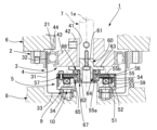
- FIG. 2 is a schematic vertical cross-sectional view showing a wave gear device incorporating an MR fluid brake mechanism as a brake mechanism;
- FIG. 2 is a schematic vertical cross-sectional view showing a wave gear device incorporating an MR fluid brake mechanism as a brake mechanism;
- a strain wave gearing device 1 comprises a rigid ring-shaped internal gear 2 and a cup-shaped flexible external gear 3 coaxially arranged therein. , a wave generator 4 coaxially attached to the inner side thereof, and a brake mechanism 5 incorporated inside the external gear 3.
- the internal gear 2 is fixed to the device housing 6,
- the wave generator 4 is a member on the input side that is coaxially connected to the motor shaft 7 and receives high-speed rotation, and the external gear 3 is a disk-shaped It is an output-side member to which the output shaft 8 is coaxially connected and which outputs reduced rotation.
- a brake mechanism 5 is attached to the external gear 3 and applies a braking force to the wave generator 4 to restrain or stop its rotation.
- the external gear 3 comprises a radially flexible cylindrical body 31 , external teeth 32 formed on the outer peripheral surface of the cylindrical body 31 on the side of the open end of the cylindrical body 31 , and the open end of the cylindrical body 31 .
- a diaphragm 33 extends radially inwardly from the opposite end, and an annular rigid boss 34 connected to the inner peripheral edge of the diaphragm 33 .
- the external gear 3 is coaxially mounted inside the internal gear 2, and the external teeth 32 face the internal teeth 21 of the internal gear 2 from the inside in the radial direction.
- the boss 34 is sandwiched between the annular pressing member 9 and the output shaft 8 , and these three members are fastened and fixed by a plurality of fastening bolts 10 .
- the wave generator 4 includes a hollow input shaft portion 42 having a shaft hole 41, a rigid plug 43 having a fixed width and an elliptical outer peripheral surface integrally formed with the circular outer peripheral surface of the input shaft portion 42, and an elliptical plug. and a wave bearing 44 mounted on its outer peripheral surface.
- the motor shaft 7 is inserted into and fixed to the shaft hole 41 of the input shaft portion 42 of the wave generator 4 .
- a portion of the cylindrical body 31 of the external gear 3 on which the external teeth 32 are formed is elliptically flexed by a wave bearing 44 attached to the plug 43 and elliptically flexed.
- the external teeth 32 positioned at both end portions of the elliptical major axis Lmax mesh with the internal teeth 21 of the internal gear 2 .
- the meshing position of the external gear 3 with respect to the internal gear 2 moves in the circumferential direction of the internal gear 2.
- the external gear 3 has 2n fewer teeth than the internal gear 2 (n: positive integer).
- n positive integer
- the external gear 3 rotates at a reduced speed as the wave generator 4 rotates.
- the reduced rotation of the external gear 3 is output from the output shaft 8 connected to the boss 34 to the load side.
- the brake mechanism 5 is incorporated between the diaphragm 33 and the boss 34 and the wave generator 4 in the inner space of the cylindrical body portion 31 of the external gear 3 .
- the brake mechanism 5 is, for example, a non-excitation electromagnetic brake.
- an electromagnet section 53 having a yoke 51 and an exciting coil 52
- an armature disc 54 that can be attracted by the electromagnet section 53
- a rotating disc A friction disc 55 and a stationary disc 56 are arranged.
- the armature disc 54 is slidable along the guide pin 57 in the direction of the axis 1a.
- a spring member 58 is arranged between the electromagnet portion 53 and the armature disk 54 .
- a spring member 58 presses the armature disc 54 against the friction disc 55 .
- the brake mechanism 5 also has a rotating shaft 60 coaxially fixed to the plug 43 of the wave generator 4 .
- the friction disk 55 is attached to the outer peripheral surface of the rotating shaft 60 so as to be slidable in the direction of the axis 1a and to rotate integrally with the rotating shaft 60 .
- the friction disc 55 has a cylindrical boss 55a and a disc main body 55b integrally formed on the outer peripheral surface of the cylindrical boss 55a. is supported via the slide guide portion 64 of the .
- the friction disc 55 is pressed against the fixed disc 56 by the armature disc 54 biased by the spring member 58 .
- a frictional force between the friction disk 55 and the fixed disk 56 acts as a braking force on the rotary shaft 60 fixed to the plug 43 .
- the yoke 51 of the electromagnet portion 53 of the brake mechanism 5 has an annular shape with a predetermined thickness. It is coaxially fixed to the boss 34 .
- a cylindrical case 59 is coaxially fixed to the outer peripheral portion of the yoke 51 , and a fixed disk 56 is coaxially fixed to the open end of the cylindrical case 59 .
- the rotary shaft 60 is formed between an insertion shaft portion 61 to be inserted into the shaft hole 41 of the plug 43 of the wave generator 4, a hollow shaft portion 62 having an outer peripheral surface supporting the friction disc 55, and these. and a large-diameter flange 63 .
- the hollow shaft portion 62 is a spline shaft having splines formed on its outer peripheral surface, and is inserted into the inner peripheral surface of the cylindrical boss 55a of the friction disc 55 having spline grooves formed thereon.
- the friction disk 55 is connected to the hollow shaft portion 62 of the rotary shaft 60 via the spline type slide guide portion 64 so as to be slidable in the direction of the axis 1a and to rotate integrally therewith.
- the friction disk 55 is supported by the inner peripheral end of the electromagnet portion 53 via the bearing 65 at the outer peripheral surface of the cylindrical boss 55a.
- an oil seal 66 (sealing member).
- a spline type slide guide portion 64 between the rotary shaft 60 and the friction disc 55 exposed on the side of the boss 34 of the external gear 3 is a seal attached to the end surface of the cylindrical boss 55a of the friction disc 55. It is closed by a cap 67 for.
- the oil seal 66 and the sealing cap 67 (sealing member) prevent the lubricant filled or supplied in the strain wave gearing 1 from entering between the friction disc 55 and the fixed disc 56 and into the spline slide guide portion 64.
- FIGS. 2A, 2B, and 2C are explanatory diagrams showing an example of the spline-type slide guide portion 64 formed between the friction disc and the rotating shaft 60.
- FIG. The male spline and female spline that constitute the slide guide portion 64 extend parallel to the axis and are formed in plural at equal angular intervals in the circumferential direction.
- the cross-sectional shapes of the male spline and female spline can be various shapes as shown in FIGS. 2A to 2C.
- the slide guide portion 64 is a mechanism in which the friction disc 55 is slidable in the direction of the axis 1a with respect to the rotary shaft 60 and is connected to the rotary shaft 60 so as to rotate integrally with the rotary shaft 60.
- it is not limited to splined mechanisms.
- FIG. 3A and 3B are explanatory diagrams showing an example of a slide guide section composed of rolling elements and splines that can be used in place of the spline type slide guide section 64.
- FIG. 3A In the slide guide portion 64A shown in FIG. 3A, spline grooves (V grooves) extending parallel to the axis are formed on the outer peripheral surface of the rotary shaft 60 and the inner peripheral surface of the friction disk 55 at equal angular intervals in the circumferential direction.
- a rolling element raceway groove 64a extending in the axial direction and having a rectangular cross section is formed between the spline groove on the inner peripheral side and the spline groove on the outer peripheral side opposed thereto. In this example, six rows of rolling element raceway grooves 64a are formed.
- One or a plurality of balls 64b are inserted into each of the rolling element raceway grooves 64a.
- the rolling element raceway grooves 64a are desirably arranged in three or more rows in the circumferential direction.
- one or a plurality of rollers 64c are inserted as rolling elements into the rolling element raceway grooves 64a having a rectangular cross section.
- an electric brake excited and unexcited electromagnetic brake
- a fluid brake or other types
- an electric brake excited and unexcited electromagnetic brake
- an MR fluid brake using a MR fluid Magnetic Rheological Fluid
- the MR fluid brake does not emit abrasion powder, noise, or vibration, and is excellent in responsiveness and controllability.
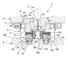
- FIG. 4A is a schematic longitudinal sectional view showing a case where an MR fluid brake mechanism 100 is attached instead of the brake mechanism 5 in the strain wave gearing 1 shown in FIG. 1A.
- the MR fluid brake mechanism 100 includes a brake case 110, a fixed disc 120 formed integrally with the brake case 110, a rotary disc 130 attached to the rotary shaft 60 so as to rotate integrally, and the fixed disc 120 and the rotary disc 130. It comprises an MR fluid 140 filled in a gap formed therebetween and an electromagnet portion 150 arranged inside the brake case 110 to excite the MR fluid 140 .
- the rotary disk 130 is a multi-layered disk, and in this example, two of them are formed on the outer peripheral surface of the hollow shaft 131 at regular intervals in the axial direction.
- Fixed discs 120 of brake case 110 have a certain gap filled with MR fluid 140 between rotating discs 130 .
- a certain gap filled with the MR fluid 140 is also formed between the outer end surfaces of the two rotary discs 130 and the brake case 110 .
- An electromagnet portion 150 for exciting the MR fluid 140 is arranged inside the brake case 110 on the outer peripheral side of the rotating disk 130 .
- a rotating shaft 60 that rotates integrally with the wave generator 4 is coaxially inserted into the hollow portion of the hollow shaft 131 of the rotating disk 130 .
- the hollow shaft 131 is connected to the rotary shaft 60 via a spline type slide guide portion 64 . Therefore, the rotating disk 130 is attached to the rotating shaft 60 so as to be slidable in the direction of the axis 1a and to rotate together with the rotating shaft 60.
- slide guide portions 64A and 64B see FIGS. 3A and 3B having a structure in which the rolling elements are inserted into the rolling element raceway grooves can also be used. .
- a space between the brake case 110 and the axially opposite sides of the hollow shaft 131 of the rotary disc 130 is sealed by oil seals 171 and 172 .
- a shaft end portion 132 of the hollow shaft 131 on the side of the boss 34 of the external gear 3 is supported by the inner peripheral surface of the brake case 110 via a bearing 180 .
- a sealing cap 190 is attached to the shaft end portion 132 to seal the hollow portion of the hollow shaft 131 .
- the MR fluid brake mechanism 100 has a structure in which fixed discs 120 and rotating discs 130 that rotate integrally with the shaft to be braked are alternately arranged, and MR fluid 140 is filled between them.
- the electromagnet part 150 is excited to apply a magnetic field to the MR fluid 140
- the MR fluid 140 changes from a liquid to a semi-solid, and a shearing force is generated between the fixed disk 120 and the rotating disk 130, which acts on the rotating disk 130 as a braking force ( resistance).
- the MR fluid brake mechanism 100 changes the viscous friction on the disk surface in accordance with the change in the magnetic field applied to the MR fluid 140, thereby continuously controlling the torque with respect to the rotational motion. It is suitable for the brake mechanism of
- the total number of multilayer discs, gaps, and surface area of the rotating portion are appropriately designed according to the coil performance and the MR fluid used.
- the kinematic viscosity of MR fluid (commercially available) for excitation varies from 2.6 to 800 mm 2 /s (40°C), but the MR fluid brake mechanism used in strain wave gearing has a viscosity of 68 mm 2 /s or less. is desirable.
- FIG. 4B is a schematic longitudinal view showing the strain wave gearing 1 in which an MR fluid brake mechanism 100A having a configuration different from that of the MR fluid brake mechanism 100 is incorporated.
- the MR fluid brake mechanism 100A is formed between a fixed disc 120A formed in the brake case 110A, a rotary disc 130A connected to the rotary shaft 60 via a slide guide portion 64A, and between the fixed disc 120A and the rotary disc 130A. It has an MR fluid 140A filled in the gap and an electromagnet part 150A for applying a magnetic field to the MR fluid 140A.
- the rotating disk 130A is configured such that three cylindrical disks are concentrically formed on the circular end surface of one radially expanding disk 134 formed on the hollow shaft 131A.
- the shape of the fixed disk 120A on the side of the brake case 110A is set so as to face these cylindrical disks with a certain gap, and the gap is filled with the MR fluid 140A.
- the electromagnet portion 150A is arranged at a position facing the cylindrical disk in the direction of the axis 1a.
- Oil seals 171A and 172A seal the space between the brake case 110A and the axially opposite sides of the hollow shaft 131A of the rotary disk 130A.
- a shaft end portion 132A of the hollow shaft 131A on the side of the boss 34 of the external gear 3 is supported by the inner peripheral surface of the brake case 110A via a bearing 180A.
- a sealing cap 190A is attached to the shaft end portion 132A to close the hollow portion of the hollow shaft 131A.
- a laminated piezoelectric actuator proposed in Japanese Patent Application Laid-Open No. 2009-264544 can be used.
- a small and compact brake mechanism capable of restraining the rotational motion around the axis of the shaft and the linear motion in the axial direction by utilizing the elastic deformation of the annular body proposed in Japanese Patent Application Laid-Open No. 2005-207544 is provided. can be used.
- the strain wave gearing 1 of this example incorporates the brake mechanism 5 (100, 100A) in the empty space inside the external gear 3 thereof.
- an actuator is constructed by connecting the strain wave gearing 1 to a motor, it is not necessary to secure an installation space in the direction of the axis 1a for arranging the brake mechanism 5 (100, 100A). Therefore, a flat brake-equipped actuator having a short axial length can be realized.
- the brake mechanism 5 (100, 100A) is fixed to the external gear 3, and its rotation shaft 60 is connected to the plug 43 of the wave generator 4 via the spline type slide guide portion 64 (64A). , the assembly of the brake mechanism 5 (100, 100A) is easy.
- the slide guide portion 64 (64A) of the brake mechanism 5 (100, 100A) is provided with sealing caps 67 (190, 190A).
- the space between the friction discs 55 (rotating discs 130, 130A) and the fixed discs 56 (120, 120A) is sealed by oil seals 66 (171, 172; 171A, 172A).
- the brake mechanism 5 (100, 100A) is isolated from the part on the strain wave gearing main body side, and it is possible to prevent foreign matter such as lubricant from entering the brake mechanism 5 (100, 100A) and causing malfunction. .
Landscapes
- Engineering & Computer Science (AREA)
- General Engineering & Computer Science (AREA)
- Mechanical Engineering (AREA)
- Retarders (AREA)
- Braking Arrangements (AREA)
Priority Applications (7)
| Application Number | Priority Date | Filing Date | Title |
|---|---|---|---|
| JP2023544853A JPWO2023032055A1 (https=) | 2021-08-31 | 2021-08-31 | |
| KR1020247002346A KR20240023639A (ko) | 2021-08-31 | 2021-08-31 | 파동기어장치 |
| EP21955945.7A EP4397886A1 (en) | 2021-08-31 | 2021-08-31 | Strain wave gear device |
| CN202180101339.9A CN117795226A (zh) | 2021-08-31 | 2021-08-31 | 波动齿轮装置 |
| PCT/JP2021/032014 WO2023032055A1 (ja) | 2021-08-31 | 2021-08-31 | 波動歯車装置 |
| US18/574,880 US20240301944A1 (en) | 2021-08-31 | 2021-08-31 | Strain wave gearing |
| TW111125919A TW202311642A (zh) | 2021-08-31 | 2022-07-11 | 諧波齒輪裝置 |
Applications Claiming Priority (1)
| Application Number | Priority Date | Filing Date | Title |
|---|---|---|---|
| PCT/JP2021/032014 WO2023032055A1 (ja) | 2021-08-31 | 2021-08-31 | 波動歯車装置 |
Publications (1)
| Publication Number | Publication Date |
|---|---|
| WO2023032055A1 true WO2023032055A1 (ja) | 2023-03-09 |
Family
ID=85410926
Family Applications (1)
| Application Number | Title | Priority Date | Filing Date |
|---|---|---|---|
| PCT/JP2021/032014 Ceased WO2023032055A1 (ja) | 2021-08-31 | 2021-08-31 | 波動歯車装置 |
Country Status (7)
| Country | Link |
|---|---|
| US (1) | US20240301944A1 (https=) |
| EP (1) | EP4397886A1 (https=) |
| JP (1) | JPWO2023032055A1 (https=) |
| KR (1) | KR20240023639A (https=) |
| CN (1) | CN117795226A (https=) |
| TW (1) | TW202311642A (https=) |
| WO (1) | WO2023032055A1 (https=) |
Citations (8)
| Publication number | Priority date | Publication date | Assignee | Title |
|---|---|---|---|---|
| JPS6098246A (ja) * | 1983-10-31 | 1985-06-01 | Shimadzu Corp | 原動装置 |
| JP2002031170A (ja) * | 2000-07-12 | 2002-01-31 | Shinko Electric Co Ltd | スプリングクローズ型電磁ブレーキ |
| JP2002257163A (ja) * | 2001-02-28 | 2002-09-11 | Daido Seimitsu Kogyo Kk | ブレーキ装置及びブレーキ装置のバックラッシュ低減方法 |
| JP2003061333A (ja) * | 2001-08-10 | 2003-02-28 | Shimazu Mectem Inc | 電動モータ |
| JP2005207544A (ja) | 2004-01-26 | 2005-08-04 | Harmonic Drive Syst Ind Co Ltd | ブレーキ機構 |
| JP2008115896A (ja) | 2006-11-01 | 2008-05-22 | Harmonic Drive Syst Ind Co Ltd | 波動歯車減速機を備えたアクチュエータ |
| JP2009264544A (ja) | 2008-04-28 | 2009-11-12 | Harmonic Drive Syst Ind Co Ltd | ブレーキ装置 |
| JP2020205742A (ja) | 2019-06-14 | 2020-12-24 | 日本電産シンポ株式会社 | 回転アクチュエータおよびロボット |
Family Cites Families (1)
| Publication number | Priority date | Publication date | Assignee | Title |
|---|---|---|---|---|
| US4506590A (en) * | 1982-07-28 | 1985-03-26 | Shimadzu Coporation | Hydraulic rotary actuator |
-
2021
- 2021-08-31 KR KR1020247002346A patent/KR20240023639A/ko not_active Ceased
- 2021-08-31 WO PCT/JP2021/032014 patent/WO2023032055A1/ja not_active Ceased
- 2021-08-31 CN CN202180101339.9A patent/CN117795226A/zh active Pending
- 2021-08-31 US US18/574,880 patent/US20240301944A1/en not_active Abandoned
- 2021-08-31 JP JP2023544853A patent/JPWO2023032055A1/ja active Pending
- 2021-08-31 EP EP21955945.7A patent/EP4397886A1/en not_active Withdrawn
-
2022
- 2022-07-11 TW TW111125919A patent/TW202311642A/zh unknown
Patent Citations (8)
| Publication number | Priority date | Publication date | Assignee | Title |
|---|---|---|---|---|
| JPS6098246A (ja) * | 1983-10-31 | 1985-06-01 | Shimadzu Corp | 原動装置 |
| JP2002031170A (ja) * | 2000-07-12 | 2002-01-31 | Shinko Electric Co Ltd | スプリングクローズ型電磁ブレーキ |
| JP2002257163A (ja) * | 2001-02-28 | 2002-09-11 | Daido Seimitsu Kogyo Kk | ブレーキ装置及びブレーキ装置のバックラッシュ低減方法 |
| JP2003061333A (ja) * | 2001-08-10 | 2003-02-28 | Shimazu Mectem Inc | 電動モータ |
| JP2005207544A (ja) | 2004-01-26 | 2005-08-04 | Harmonic Drive Syst Ind Co Ltd | ブレーキ機構 |
| JP2008115896A (ja) | 2006-11-01 | 2008-05-22 | Harmonic Drive Syst Ind Co Ltd | 波動歯車減速機を備えたアクチュエータ |
| JP2009264544A (ja) | 2008-04-28 | 2009-11-12 | Harmonic Drive Syst Ind Co Ltd | ブレーキ装置 |
| JP2020205742A (ja) | 2019-06-14 | 2020-12-24 | 日本電産シンポ株式会社 | 回転アクチュエータおよびロボット |
Also Published As
| Publication number | Publication date |
|---|---|
| CN117795226A (zh) | 2024-03-29 |
| EP4397886A1 (en) | 2024-07-10 |
| KR20240023639A (ko) | 2024-02-22 |
| US20240301944A1 (en) | 2024-09-12 |
| TW202311642A (zh) | 2023-03-16 |
| JPWO2023032055A1 (https=) | 2023-03-09 |
Similar Documents
| Publication | Publication Date | Title |
|---|---|---|
| CN103782491B (zh) | 带减速机的马达 | |
| JP2021021488A (ja) | クラッチ装置 | |
| JP5439935B2 (ja) | 駆動力伝達装置 | |
| WO2021020321A1 (ja) | クラッチ装置 | |
| CN114144596A (zh) | 离合器装置 | |
| EP1900081A1 (en) | Direct drive electromechanical linear actuators | |
| CN114144599A (zh) | 离合器装置 | |
| JP5496836B2 (ja) | 電動式直動アクチュエータおよび電動式ディスクブレーキ装置 | |
| JP5082725B2 (ja) | トルク変動吸収装置 | |
| WO2023032055A1 (ja) | 波動歯車装置 | |
| CN115681365A (zh) | 盘式制动装置用马达齿轮单元及盘式制动装置 | |
| CN109923331A (zh) | 电动致动器 | |
| JP4959639B2 (ja) | 電動ブレーキ装置 | |
| JP5797929B2 (ja) | 電動式直動アクチュエータおよび電動式ディスクブレーキ装置 | |
| JP7563164B2 (ja) | 回転式アクチュエータ | |
| WO2018088244A1 (ja) | 直動式電動アクチュエータ | |
| WO2024023918A1 (ja) | 電磁摩擦クラッチ装置 | |
| JP7456370B2 (ja) | クラッチ装置 | |
| JP7854817B2 (ja) | アクチュエータ | |
| JP2022170458A (ja) | クラッチアクチュエータ | |
| JP2022119644A (ja) | クラッチ装置 | |
| TWI920346B (zh) | 諧波齒輪裝置 | |
| JP7456362B2 (ja) | クラッチ装置 | |
| JP2012241825A (ja) | 電動式直動アクチュエータおよび電動式ディスクブレーキ装置 | |
| WO2022118846A1 (ja) | クラッチ装置 |
Legal Events
| Date | Code | Title | Description |
|---|---|---|---|
| 121 | Ep: the epo has been informed by wipo that ep was designated in this application |
Ref document number: 21955945 Country of ref document: EP Kind code of ref document: A1 |
|
| WWE | Wipo information: entry into national phase |
Ref document number: 2023544853 Country of ref document: JP |
|
| ENP | Entry into the national phase |
Ref document number: 20247002346 Country of ref document: KR Kind code of ref document: A |
|
| WWE | Wipo information: entry into national phase |
Ref document number: 1020247002346 Country of ref document: KR |
|
| WWE | Wipo information: entry into national phase |
Ref document number: 202180101339.9 Country of ref document: CN |
|
| WWE | Wipo information: entry into national phase |
Ref document number: 2021955945 Country of ref document: EP |
|
| NENP | Non-entry into the national phase |
Ref country code: DE |
|
| ENP | Entry into the national phase |
Ref document number: 2021955945 Country of ref document: EP Effective date: 20240402 |
|
| WWR | Wipo information: refused in national office |
Ref document number: 1020247002346 Country of ref document: KR |