EP4397886A1 - Strain wave gear device - Google Patents
Strain wave gear device Download PDFInfo
- Publication number
- EP4397886A1 EP4397886A1 EP21955945.7A EP21955945A EP4397886A1 EP 4397886 A1 EP4397886 A1 EP 4397886A1 EP 21955945 A EP21955945 A EP 21955945A EP 4397886 A1 EP4397886 A1 EP 4397886A1
- Authority
- EP
- European Patent Office
- Prior art keywords
- toothed gear
- brake mechanism
- brake
- disc
- strain wave
- Prior art date
- Legal status (The legal status is an assumption and is not a legal conclusion. Google has not performed a legal analysis and makes no representation as to the accuracy of the status listed.)
- Withdrawn
Links
Images

Classifications
-
- F—MECHANICAL ENGINEERING; LIGHTING; HEATING; WEAPONS; BLASTING
- F16—ENGINEERING ELEMENTS AND UNITS; GENERAL MEASURES FOR PRODUCING AND MAINTAINING EFFECTIVE FUNCTIONING OF MACHINES OR INSTALLATIONS; THERMAL INSULATION IN GENERAL
- F16H—GEARING
- F16H1/00—Toothed gearings for conveying rotary motion
- F16H1/28—Toothed gearings for conveying rotary motion with gears having orbital motion
- F16H1/32—Toothed gearings for conveying rotary motion with gears having orbital motion in which the central axis of the gearing lies inside the periphery of an orbital gear
-
- F—MECHANICAL ENGINEERING; LIGHTING; HEATING; WEAPONS; BLASTING
- F16—ENGINEERING ELEMENTS AND UNITS; GENERAL MEASURES FOR PRODUCING AND MAINTAINING EFFECTIVE FUNCTIONING OF MACHINES OR INSTALLATIONS; THERMAL INSULATION IN GENERAL
- F16H—GEARING
- F16H49/00—Other gearings
- F16H49/001—Wave gearings, e.g. harmonic drive transmissions
-
- F—MECHANICAL ENGINEERING; LIGHTING; HEATING; WEAPONS; BLASTING
- F16—ENGINEERING ELEMENTS AND UNITS; GENERAL MEASURES FOR PRODUCING AND MAINTAINING EFFECTIVE FUNCTIONING OF MACHINES OR INSTALLATIONS; THERMAL INSULATION IN GENERAL
- F16D—COUPLINGS FOR TRANSMITTING ROTATION; CLUTCHES; BRAKES
- F16D55/00—Brakes with substantially-radial braking surfaces pressed together in axial direction, e.g. disc brakes
- F16D55/02—Brakes with substantially-radial braking surfaces pressed together in axial direction, e.g. disc brakes with axially-movable discs or pads pressed against axially-located rotating members
-
- F—MECHANICAL ENGINEERING; LIGHTING; HEATING; WEAPONS; BLASTING
- F16—ENGINEERING ELEMENTS AND UNITS; GENERAL MEASURES FOR PRODUCING AND MAINTAINING EFFECTIVE FUNCTIONING OF MACHINES OR INSTALLATIONS; THERMAL INSULATION IN GENERAL
- F16D—COUPLINGS FOR TRANSMITTING ROTATION; CLUTCHES; BRAKES
- F16D57/00—Liquid-resistance brakes; Brakes using the internal friction of fluids or fluid-like media, e.g. powders
- F16D57/002—Liquid-resistance brakes; Brakes using the internal friction of fluids or fluid-like media, e.g. powders comprising a medium with electrically or magnetically controlled internal friction, e.g. electrorheological fluid, magnetic powder
-
- F—MECHANICAL ENGINEERING; LIGHTING; HEATING; WEAPONS; BLASTING
- F16—ENGINEERING ELEMENTS AND UNITS; GENERAL MEASURES FOR PRODUCING AND MAINTAINING EFFECTIVE FUNCTIONING OF MACHINES OR INSTALLATIONS; THERMAL INSULATION IN GENERAL
- F16D—COUPLINGS FOR TRANSMITTING ROTATION; CLUTCHES; BRAKES
- F16D65/00—Parts or details
- F16D65/005—Components of axially engaging brakes not otherwise provided for
-
- F—MECHANICAL ENGINEERING; LIGHTING; HEATING; WEAPONS; BLASTING
- F16—ENGINEERING ELEMENTS AND UNITS; GENERAL MEASURES FOR PRODUCING AND MAINTAINING EFFECTIVE FUNCTIONING OF MACHINES OR INSTALLATIONS; THERMAL INSULATION IN GENERAL
- F16H—GEARING
- F16H49/00—Other gearings
- F16H49/001—Wave gearings, e.g. harmonic drive transmissions
- F16H2049/003—Features of the flexsplines therefor
Definitions
- Actuators in which strain wave gearings are used are typically configured such that a motor, a brake, a detector, and a strain wave gearing are arranged in an axial direction.
- an actuator is configured such that a strain wave gearing is disposed on a load side, and a brake and a detection unit are disposed on a counter-load side, so as to sandwich a motor.
- an electromagnetic brake is used as the brake, but other types of brakes, such as MR fluid brakes or other fluid brakes, are also known as brakes that can be used (for example, see the brakes disclosed in Patent Documents 3 and 4).
- an actuator employing a strain wave gearing, a motor, a brake, or other structures that are linked in the axial direction increases the axial length of the actuator. It is difficult to keep the axial length of the actuator from increasing so as to achieve a flatter profile.
- the strain wave gearing according to the present invention is provided with a rigid internally toothed gear, a flexible externally toothed gear that is coaxially disposed inside the internally toothed gear, and a wave generator coaxially disposed inside the externally toothed gear, the strain wave gearing being characterized by comprising a brake mechanism that is incorporated inside the externally toothed gear in addition to the wave generator, the brake mechanism constraining or preventing rotation of the wave generator.
- a strain wave gearing comprising a brake can be realized without increasing the axial length of the strain wave gearing.
- using the above-described strain wave gearing makes it possible to keep the axial length of an actuator equipped with a brake from increasing so as to achieve a flatter profile.
- Embodiments of a strain wave gearing to which the present invention is applied are described below with reference to the accompanying drawings.
- the embodiments illustrate cases in which the present invention is applied to cup-shaped strain wave gearings, but the present invention can also be applied to top-hat-shaped strain wave gearings in a similar manner.
- the present invention can additionally be applied to pancake-shaped strain wave gearings comprising two internally toothed gears and a cylindrical flexible externally toothed gear.
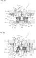
- the strain wave gearing 1 comprises an annular rigid internally toothed gear 2, a cup-shaped flexible externally toothed gear 3 that is coaxially disposed inside the internally toothed gear 2, a wave generator 4 that is coaxially mounted inside the externally toothed gear 3, and a brake mechanism 5 that is incorporated inside the externally toothed gear 3.
- the wave generator 4 is provided with a hollow input shaft section 42 that is provided with a shaft hole 41, a rigid plug 43 of uniform width that is provided with an ellipsoidal outer peripheral surface and is formed integrally with the cylindrical outer peripheral surface of the input shaft section 42, and a wave bearing 44 that is mounted on the ellipsoidal outer peripheral surface of the plug 43.
- a motor shaft 7 is inserted into the shaft hole 41 in the input shaft 42 of the wave generator 4 and fixed to the wave generator 4.
- the wave bearing 44 which is mounted on the plug 43 and is caused to flex into an ellipsoidal shape, causes the portion of the cylindrical barrel part 31 where the external teeth 32 are formed on the externally toothed gear 3 to flex into an ellipsoidal shape.
- the external teeth 32 that are positioned at both end portions on a long axis Lmax of the ellipsoidal shape mesh with the internal teeth 21 of the internally toothed gear 2.
- the externally toothed gear 3 has 2n fewer teeth than the internally toothed gear 2 (where n is a positive integer).
- n is a positive integer.
- the externally toothed gear 3 rotates at a reduced speed in association with rotation of the wave generator 4.
- the reduced rotation of the externally toothed gear 3 is outputted to the load side from the output shaft 8, which is linked to the boss 34 of the externally toothed gear 3.
- the brake mechanism 5 is incorporated within an internal space in the cylindrical barrel part 31 of the externally toothed gear 3 at a location between the wave generator 4 and the diaphragm 33 and boss 34.
- the brake mechanism 5 is, for example, a power-off activated type electromagnetic brake.
- an electromagnet part 53 that is provided with a yoke 51 and an excitation coil 52
- an armature disc 54 that can be attracted by the electromagnet part 53
- a friction disc 55 and a fixed disc 56 that are rotating discs are disposed along the direction of an axis 1a from the boss 34 side toward the plug 43.
- the armature disc 54 is capable of sliding in the direction of the axis 1a along a guide pin 57.
- a spring member 58 is disposed between the electromagnet part 53 and the armature disc 54. The armature disc 54 is pressed toward the friction disc 55 by the spring member 58.
- the brake mechanism 5 is also provided with a rotating shaft 60 that is coaxially fixed to the plug 43 of the wave generator 4.
- the friction disc 55 is attached to the outer peripheral surface of the rotating shaft 60 so as to be capable of sliding in the direction of the axis 1a and so as to rotate integrally with the rotating shaft 60.
- the friction disc 55 is provided with a cylindrical boss 55a and a disc body part 55b that is formed integrally with the outer peripheral surface of the cylindrical boss 55a, and the inner peripheral surface of the cylindrical boss 55a is supported on the outer peripheral surface of the rotating shaft 60 via a splined slide guide part 64.
- the friction disc 55 is pressed toward the fixed disc 56 by the armature disc 54, which is biased by the spring member 58. Frictional force between the friction disc 55 and the fixed disc 56 acts as braking force on the rotating shaft 60, which is fixed to the plug 43.
- the electromagnet part 53 is excited, the armature disc 54 is attracted toward the electromagnet part 53 against the spring force, the friction disc 55 is released from the fixed disc 56, and the braking force applied to the rotating shaft 60 is canceled.
- the yoke 51 of the electromagnet part 53 of the brake mechanism 5 is formed in a cylindrical shape having a prescribed thickness and is coaxially fixed to the boss 34 of the externally toothed gear 3 by fastening bolts or other fastening fixtures (not shown), with the pressing member 9 interposed therebetween.
- a cylindrical case 59 is coaxially fixed to the outer peripheral section of the yoke 51, and the fixed disc 56 is coaxially fixed to an open end of the cylindrical case 59.
- the rotating shaft 60 is provided with an insertion shaft section 61 that is inserted into the shaft hole 41 in the plug 43 of the wave generator 4, a hollow shaft section 62 that is provided with an outer peripheral surface by which the friction disc 55 is supported, and a large-diameter flange 63 that is formed between the insertion shaft section 61 and the hollow shaft section 62.
- the hollow shaft section 62 is a spline shaft having splines formed on the outer peripheral surface thereof, the hollow shaft section 62 being inserted into the inner peripheral surface of the cylindrical boss 55a of the friction disc 55, in which spline grooves are formed.
- the friction disc 55 is linked to the hollow shaft section 62 of the rotating shaft 60 via the splined slide guide part 64 so as to rotate integrally with the rotating shaft 60 in a state of being capable of sliding in the direction of the axis 1a. Additionally, the outer peripheral surface of the cylindrical boss 55a of the friction disc 55 is supported by an inner peripheral end section of the electromagnet part 53 via a bearing 65.
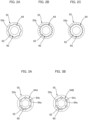
- FIGS. 2A, 2B, and 2C show examples of the splined slide guide part 64, which is formed between the friction disc and the rotating shaft 60.
- a plurality of male-side splines and female-side splines that constitute the slide guide part 64 are formed at equiangular intervals in the circumferential direction, the male-side and female-side splines extending parallel to the axis.
- a variety of shapes can be employed for the cross-sectional shapes of the male-side and female-side splines, as shown in FIGS. 2A to 2C .
- FIGS. 3A and 3B show examples of a slide guide part that is configured from rolling elements and splines, said slide guide part being usable in lieu of the splined slide guide part 64.
- spline grooves V grooves
- FIGS. 3A and 3B show examples of a slide guide part that is configured from rolling elements and splines, said slide guide part being usable in lieu of the splined slide guide part 64.
- spline grooves V grooves
- Rolling-element raceway grooves 64a of rectangular cross-section that extend in the axial direction are formed between the inner-peripheral-side spline grooves and the outer-peripheral-side spline grooves that face the inner-peripheral-side spline grooves.
- six rolling-element raceway grooves 64a are formed.
- One or a plurality of balls 64b (rolling elements) are inserted into each of the rolling-element raceway grooves 64a. It is desirable for there to be three or more rolling-element raceway grooves 64a in the circumferential direction.
- one or a plurality of rollers 64c serving as rolling elements are inserted into the rolling-element raceway grooves 64 of rectangular cross-section.
- An electric brake power-on activated type or power-off activated type electromagnetic brake
- a fluid brake or other types of brakes
- MR fluid magneto-rheological fluid
- MR fluid brakes do not release abrasive powders or emit sound/vibration and have exceptional responsiveness/control properties.
- a shaft end section 132 of the hollow shaft 131 that is located on the side where the boss 34 of the externally toothed gear 3 is located is supported by the inner peripheral surface of the brake case 110 via a bearing 180.
- a sealing cap 190 is attached to the shaft end section 132 to seal the hollow section within the hollow shaft 131.
- the viscous friction of the disc surfaces is changed in association with changes in the magnetic field applied to the MR fluid 140, thereby making it possible to continuously control torque relative to a rotation action, this feature being suited for the brake mechanism of the strain wave gearing 1.
- the total number of multilayer discs, features pertaining to the gaps, and the surface area of rotating parts are designed, as appropriate, in accordance with the coil performance and the MR fluid used.
- the dynamic viscosity for excitation of the (commercially available) MR fluid varies at 2.6-800 mm 2 /s (40°C), but it is desirable for the dynamic viscosity in an MR fluid brake mechanism that is used in a strain wave gearing to be 68 mm 2 /s or lower.
- the brake mechanism 5 (100, 100A) is fixed to the externally toothed gear 3, and the rotating shaft 60 of the brake mechanism 5 (100, 100A) is linked to the plug 43 of the wave generator 4 via the splined slide guide part 64 (64A), it is easy to assemble the brake mechanism 5 (100, 100A).
Landscapes
- Engineering & Computer Science (AREA)
- General Engineering & Computer Science (AREA)
- Mechanical Engineering (AREA)
- Retarders (AREA)
- Braking Arrangements (AREA)
Applications Claiming Priority (1)
| Application Number | Priority Date | Filing Date | Title |
|---|---|---|---|
| PCT/JP2021/032014 WO2023032055A1 (ja) | 2021-08-31 | 2021-08-31 | 波動歯車装置 |
Publications (1)
| Publication Number | Publication Date |
|---|---|
| EP4397886A1 true EP4397886A1 (en) | 2024-07-10 |
Family
ID=85410926
Family Applications (1)
| Application Number | Title | Priority Date | Filing Date |
|---|---|---|---|
| EP21955945.7A Withdrawn EP4397886A1 (en) | 2021-08-31 | 2021-08-31 | Strain wave gear device |
Country Status (7)
| Country | Link |
|---|---|
| US (1) | US20240301944A1 (https=) |
| EP (1) | EP4397886A1 (https=) |
| JP (1) | JPWO2023032055A1 (https=) |
| KR (1) | KR20240023639A (https=) |
| CN (1) | CN117795226A (https=) |
| TW (1) | TW202311642A (https=) |
| WO (1) | WO2023032055A1 (https=) |
Family Cites Families (9)
| Publication number | Priority date | Publication date | Assignee | Title |
|---|---|---|---|---|
| US4506590A (en) * | 1982-07-28 | 1985-03-26 | Shimadzu Coporation | Hydraulic rotary actuator |
| JPS6098246A (ja) * | 1983-10-31 | 1985-06-01 | Shimadzu Corp | 原動装置 |
| JP2002031170A (ja) * | 2000-07-12 | 2002-01-31 | Shinko Electric Co Ltd | スプリングクローズ型電磁ブレーキ |
| JP2002257163A (ja) * | 2001-02-28 | 2002-09-11 | Daido Seimitsu Kogyo Kk | ブレーキ装置及びブレーキ装置のバックラッシュ低減方法 |
| JP2003061333A (ja) * | 2001-08-10 | 2003-02-28 | Shimazu Mectem Inc | 電動モータ |
| JP4240384B2 (ja) | 2004-01-26 | 2009-03-18 | 株式会社ハーモニック・ドライブ・システムズ | ブレーキ機構 |
| JP4833028B2 (ja) | 2006-11-01 | 2011-12-07 | 株式会社ハーモニック・ドライブ・システムズ | 波動歯車減速機を備えたアクチュエータ |
| JP2009264544A (ja) | 2008-04-28 | 2009-11-12 | Harmonic Drive Syst Ind Co Ltd | ブレーキ装置 |
| JP7512560B2 (ja) | 2019-06-14 | 2024-07-09 | ニデックドライブテクノロジー株式会社 | 回転アクチュエータおよびロボット |
-
2021
- 2021-08-31 KR KR1020247002346A patent/KR20240023639A/ko not_active Ceased
- 2021-08-31 WO PCT/JP2021/032014 patent/WO2023032055A1/ja not_active Ceased
- 2021-08-31 CN CN202180101339.9A patent/CN117795226A/zh active Pending
- 2021-08-31 US US18/574,880 patent/US20240301944A1/en not_active Abandoned
- 2021-08-31 JP JP2023544853A patent/JPWO2023032055A1/ja active Pending
- 2021-08-31 EP EP21955945.7A patent/EP4397886A1/en not_active Withdrawn
-
2022
- 2022-07-11 TW TW111125919A patent/TW202311642A/zh unknown
Also Published As
| Publication number | Publication date |
|---|---|
| WO2023032055A1 (ja) | 2023-03-09 |
| CN117795226A (zh) | 2024-03-29 |
| KR20240023639A (ko) | 2024-02-22 |
| US20240301944A1 (en) | 2024-09-12 |
| TW202311642A (zh) | 2023-03-16 |
| JPWO2023032055A1 (https=) | 2023-03-09 |
Similar Documents
| Publication | Publication Date | Title |
|---|---|---|
| US9624994B2 (en) | Electric linear motion actuator and electric brake system | |
| CN100480532C (zh) | 致动机构及制动组件 | |
| JP3436590B2 (ja) | 締結装置 | |
| EP2532915A1 (en) | Disk brake device equipped with electric parking mechanism | |
| EP2345830A1 (en) | Electric linear actuator and electric brake device | |
| CN114144596A (zh) | 离合器装置 | |
| EP3040573B1 (en) | Electric linear motion actuator and electric disc brake device | |
| US8641537B2 (en) | Damper mechanism | |
| EP4397886A1 (en) | Strain wave gear device | |
| US20080011574A1 (en) | Clutch Structure For Mechanical Automatic Transmission | |
| JP5082725B2 (ja) | トルク変動吸収装置 | |
| JP7833914B2 (ja) | ブレーキ装置用無励磁作動型ブレーキ及びディスクブレーキ装置 | |
| CN115681365A (zh) | 盘式制动装置用马达齿轮单元及盘式制动装置 | |
| JP5946399B2 (ja) | 電動式ディスクブレーキ装置 | |
| CN114396442A (zh) | 一种制动装置、动力总成以及设备 | |
| WO2018096939A1 (ja) | 電動アクチュエータ | |
| CN113280062A (zh) | 一种自锁式操纵机构制动器 | |
| KR20220158757A (ko) | 원형파 드라이브 | |
| JP4959639B2 (ja) | 電動ブレーキ装置 | |
| EP4733618A1 (en) | Electro-mechanical brake for integrated drive shaft, and vehicle | |
| JP2022119644A (ja) | クラッチ装置 | |
| EP4438916B1 (en) | Improved friction clutch system | |
| US20250180084A1 (en) | Brake device for a motor vehicle | |
| JP2026072266A (ja) | セルフロック装置および駆動装置 | |
| JP2025117301A (ja) | ボールねじ装置 |
Legal Events
| Date | Code | Title | Description |
|---|---|---|---|
| STAA | Information on the status of an ep patent application or granted ep patent |
Free format text: STATUS: THE INTERNATIONAL PUBLICATION HAS BEEN MADE |
|
| PUAI | Public reference made under article 153(3) epc to a published international application that has entered the european phase |
Free format text: ORIGINAL CODE: 0009012 |
|
| STAA | Information on the status of an ep patent application or granted ep patent |
Free format text: STATUS: REQUEST FOR EXAMINATION WAS MADE |
|
| 17P | Request for examination filed |
Effective date: 20231229 |
|
| AK | Designated contracting states |
Kind code of ref document: A1 Designated state(s): AL AT BE BG CH CY CZ DE DK EE ES FI FR GB GR HR HU IE IS IT LI LT LU LV MC MK MT NL NO PL PT RO RS SE SI SK SM TR |
|
| STAA | Information on the status of an ep patent application or granted ep patent |
Free format text: STATUS: THE APPLICATION HAS BEEN WITHDRAWN |
|
| 18W | Application withdrawn |
Effective date: 20240821 |