WO2023021644A1 - 乗りかごおよびエレベーター - Google Patents
乗りかごおよびエレベーター Download PDFInfo
- Publication number
- WO2023021644A1 WO2023021644A1 PCT/JP2021/030316 JP2021030316W WO2023021644A1 WO 2023021644 A1 WO2023021644 A1 WO 2023021644A1 JP 2021030316 W JP2021030316 W JP 2021030316W WO 2023021644 A1 WO2023021644 A1 WO 2023021644A1
- Authority
- WO
- WIPO (PCT)
- Prior art keywords
- car
- pulley
- floor
- support beam
- floor support
- Prior art date
- Legal status (The legal status is an assumption and is not a legal conclusion. Google has not performed a legal analysis and makes no representation as to the accuracy of the status listed.)
- Ceased
Links
Images


Classifications
-
- B—PERFORMING OPERATIONS; TRANSPORTING
- B66—HOISTING; LIFTING; HAULING
- B66B—ELEVATORS; ESCALATORS OR MOVING WALKWAYS
- B66B11/00—Main component parts of lifts in, or associated with, buildings or other structures
- B66B11/02—Cages, i.e. cars
- B66B11/0206—Car frames
-
- B—PERFORMING OPERATIONS; TRANSPORTING
- B66—HOISTING; LIFTING; HAULING
- B66B—ELEVATORS; ESCALATORS OR MOVING WALKWAYS
- B66B15/00—Main component parts of mining-hoist winding devices
- B66B15/02—Rope or cable carriers
- B66B15/04—Friction sheaves; "Koepe" pulleys
Definitions
- the present invention relates to cars and elevators.
- elevator cars are equipped with tie rods that suppress tilting of the car floor.
- the car floor is supported by floor support beams.
- the inclination of the car floor is suppressed by applying an upward force to the floor support beams via the tie rods.
- the technology described in Patent Document 1 is known.
- the car outer dimension is the dimension planned for installing equipment other than the car on the hoistway (hereinafter referred to as "hoistway equipment"), and as long as the car is designed within this planned dimension, There is no interference between the car and hoistway equipment. For this reason, equipment such as counterweights, which are one type of hoistway equipment, are designed to fit between the car exterior and the walls of the hoistway.
- hoistway equipment equipment such as counterweights, which are one type of hoistway equipment
- the protrusion of the tie rod imposes restrictions on the layout and design of the hoistway equipment. Also, at construction sites where elevator installation work is carried out, it is necessary to check whether the elevator car and hoistway equipment interfere with each other, and if they interfere, review the layout of the hoistway equipment and the structure of the elevator car.
- An object of the present invention is to provide a car and an elevator capable of suppressing inclination of the car floor without providing tie rods.
- the present application includes a plurality of means for solving the above problems.
- One of them is a car frame having a pair of vertical frames and a lower frame connecting the lower ends of the pair of vertical frames, and a car floor.
- a connection member that connects the vertical frame and the floor support beam.
- This car has a structure in which an upward force applied to the pulley support member and the floor support beam by the main rope wound around the pulley under the car is received by the connecting member and the vertical frame.
- FIG. 1 is a schematic configuration diagram of an elevator according to an embodiment
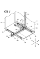
- FIG. It is a perspective view showing the appearance of the car concerning an embodiment. It is the figure which looked at the car shown in FIG. 2 from the diagonally downward direction. It is a figure which shows the structure of an anti-vibration part. It is the figure which looked at the principal part of the car shown in FIG. 2 from the left-right direction. It is the figure which looked at the principal part of the car shown in FIG. 2 from the diagonal direction. It is a figure which shows the structure of an intermediate member. It is a schematic diagram which shows the car which concerns on a comparative form. It is a mimetic diagram showing a car concerning an embodiment.
- FIG. 1 is a schematic configuration diagram of an elevator according to an embodiment.
- the elevator includes a hoisting machine 1 , a main rope 2 , a car 3 , a counterweight 5 and a pulley 6 .
- the car 3 has a pair of under-car pulleys 4A and 4B. The car 3 ascends and descends on the hoistway 50 according to the movement of the main rope 2 wound around the pair of lower car pulleys 4A and 4B.
- the hoist 1 is a device that hoists the main rope 2 in order to raise and lower the car 3.
- the hoisting machine 1 is installed above the hoistway 50 .
- One end and the other end of the main rope 2 are fixed to the top of the hoistway 50, respectively.
- the main rope 2 is wound around a pair of under-car pulleys 4A and 4B, the hoisting machine 1, and a pulley 6. - ⁇
- the car 3 ascends and descends while being guided by a pair of guide rails (not shown).
- a pair of under-car pulleys 4A and 4B are arranged below the car 3 .
- the counterweight 5 is a weight for reducing the load on the hoisting machine 1 by balancing the mass with the car 3 .
- the counterweight 5 moves up and down in the opposite direction to the car 3 when the main rope 2 is hoisted by the hoisting machine 1 .
- the pulley 6 is arranged above the counterweight 5 and moves up and down
- FIG. 2 is a perspective view showing the appearance of the car according to the embodiment.
- each direction of front and back, up and down, left and right is defined with reference to the line of sight of the elevator user facing the car 3 .
- the front side is the front
- the back side is the rear
- the upper side is the upper side
- the lower side is the lower side
- the left side is the left side
- the right side is the right side.
- the car 3 includes a car frame 7 and a car room 8 arranged inside the car frame 7 .
- the car room 8 has an accommodation space inside for carrying luggage and people.
- the car room 8 is formed by a car floor 12 , side plates 13 and a ceiling 15 .
- the car floor 12 and the ceiling 15 are arranged to face each other in the vertical direction with the accommodation space interposed therebetween.
- the side plates 13 are arranged so as to surround the storage space on all sides except for the car door 18 portion.
- the car frame 7 is formed in a vertically long rectangle when viewed from the front-rear direction.
- the car frame 7 is arranged so as to surround the car room 8.
- the car frame 7 includes an upper frame 9 arranged above the car chamber 8, a lower frame 10 arranged below the car chamber 8 (see FIG. 3), and It has a pair of vertical frames 11A and 11B.
- the upper frame 9 is a member that extends long in the left-right direction.
- the upper frame 9 extends horizontally between the upper ends of the pair of vertical frames 11A and 11B.
- One longitudinal end of the upper frame 9 is fixed to the upper end of the vertical frame 11A, and the other longitudinal end of the upper frame 9 is fixed to the upper end of the vertical frame 11B.
- the upper ends of the pair of vertical frames 11A and 11B are connected by the upper frame 9. As shown in FIG.
- a pair of vertical frames 11A and 11B are arranged to face each other in the left-right direction.
- Each of the vertical frames 11A and 11B is a member elongated in the vertical direction.
- Each vertical frame 11A, 11B is supported by the pair of guide rails described above.
- the guide rail is an elongated member installed vertically on the wall of the hoistway 50 .
- the lower frame 10 is arranged at a position facing the upper frame 9 with the car room 8 interposed therebetween.
- the lower frame 10 is a member that extends long in the left-right direction.
- the lower frame 10 spans horizontally between the lower ends of the pair of vertical frames 11A and 11B.
- One longitudinal end of the lower frame 10 is fixed to the lower end of the vertical frame 11A, and the other longitudinal end of the lower frame 10 is fixed to the lower end of the vertical frame 11B.
- the lower ends of the pair of vertical frames 11A and 11B are connected by the lower frame 10. As shown in FIG.
- the lower frame 10 supports the car floor 12 via a pair of floor support beams 14A and 14B.
- a pair of floor support beams 14A and 14B are beams that support the car floor 12.
- Vibration isolating portions 20 are provided at both ends in the longitudinal direction of the floor support beam 14A, and vibration isolating portions 20 are also provided at both ends in the longitudinal direction of the floor support beam 14B.
- the vibration isolator 20 is a portion that suppresses vibration of the car room 8 including the car floor 12 .
- the car floor 12 is supported by a pair of floor support beams 14A and 14B via a plurality of (four in this embodiment) vibration isolating sections 20 .
- the vibration isolator 20 includes two coil springs 20A, a plate-shaped spring pedestal 20B attached to the bottom surface of the car floor 12, and a plate-shaped spring pedestal attached to the bottom surface of the floor support beam 14A. (not shown).
- the coil spring 20A is an elastic member for vibration isolation.
- the spring seat 20B is provided with a spring receiving hole (not shown) for receiving the end of the coil spring 20A. This point also applies to the spring pedestals attached to the bottom surfaces of the floor support beams 14A.
- the vibration isolator 20 is not limited to a configuration using a coil spring, and may be configured using rubber, for example.
- the floor support beam 14A is arranged at one longitudinal end (right end) of the lower frame 10, and the floor support beam 14B is arranged at the other longitudinal end (left end) of the lower frame 10.
- Each of the floor support beams 14A and 14B is placed on the lower frame 10 and fixed to the upper surface of the lower frame 10 by bolts (not shown).
- Each of the floor support beams 14A, 14B is horizontally arranged in a direction perpendicular to the lower frame 10. As shown in FIG. Specifically, the lower frame 10 is arranged parallel to the left-right direction, and the respective floor support beams 14A and 14B are arranged parallel to the front-rear direction.
- Each of the floor support beams 14A, 14B is a member that extends long in the front-rear direction and has a closed cross-sectional structure.
- a closed cross-sectional structure means a structure with a closed cross section, more specifically, a rectangular or cylindrical cross-sectional structure.
- each of the floor support beams 14A, 14B has a rectangular cross-sectional structure.
- a car door 18 is installed in the front part of the car room 8 .
- the car door 18 is provided so as to be openable and closable in the left-right direction.
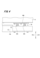
- a pair of under-car pulleys 4A and 4B are arranged below the cage 8, as shown in FIG.
- the under-car pulleys 4A and 4B are arranged in front of the vertical frames 11A and 11B.
- One under-car pulley 4A is attached to the floor support beam 14A, and the other under-car pulley 4B is attached to the floor support beam 14B.
- the mounting structure of the under-car pulleys 4A and 4B will be described in detail below.
- the mounting structure of the under-car pulley 4A to the floor support beam 14A and the mounting structure of the under-car pulley 4B to the floor support beam 14B are common to each other. Therefore, in this specification, only the mounting structure of the under-car pulley 4A to the floor support beam 14A will be described in order to avoid duplication of description.
- the under-car pulley 4A is supported by a pair of pulley support brackets 16A and 16B.
- a pair of pulley support brackets 16A and 16B correspond to pulley support members.
- the pair of pulley support brackets 16A and 16B are arranged to face each other in the longitudinal direction with the under-car pulley 4A interposed therebetween.
- the upper end of the pulley support bracket 16A is fixed to the lower surface of the floor support beam 14A using bolts (not shown).
- the upper end of the pulley support bracket 16B is fixed to the lower surface of the floor support beam 14A using bolts (not shown).
- a pair of pulley support brackets 16A and 16B rotatably supports the rotating shaft of the under-car pulley 4A. Further, the under-car pulley 4A is arranged below the car floor 12, and the floor support beam 14A is arranged between the under-car pulley 4A and the car floor 12 in the vertical direction.
- a rope guide 17 is attached to the lower ends of the pair of pulley support brackets 16A and 16B.
- the rope guide 17 is a rail-shaped member elongated in the left-right direction.
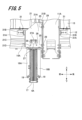
- One longitudinal end of the rope guide 17 is fixed by a bolt 19 (see FIG. 5) to the lower ends of a pair of pulley support brackets 16A and 16B that support the lower car pulley 4A.
- the other end of the rope guide 17 in the longitudinal direction is fixed by bolts (not shown) to the lower ends of a pair of pulley support brackets 16A and 16B that support the lower car pulley 4B.
- the rope guide 17 serves to protect the main rope 2 so that foreign objects are not caught in the main rope 2 wound around the under-car pulleys 4A and 4B.
- the car 3 includes a connecting member 21 connecting the vertical frame 11A and the floor supporting beam 14A, and a connecting member (not shown) connecting the vertical frame 11B and the floor supporting beam 14B.
- a connecting member 21 connecting the vertical frame 11A and the floor supporting beam 14A
- a connecting member (not shown) connecting the vertical frame 11B and the floor supporting beam 14B.
- the mounting structure of the connecting member 21 and the mounting structure of the connecting member (not shown) are common to each other. Therefore, in this specification, only the attachment structure of the connecting member 21 will be described in order to avoid duplication of description.
- the connecting member 21 is arranged directly above the under-car pulley 4A when viewed from the left-right direction corresponding to the depth direction of the paper.
- the connecting member 21 is an integral structure obtained by bending a metal plate.
- the connecting member 21 integrally includes a first plate portion 21A, a second plate portion 21B, a third plate portion 21C, and a fourth plate portion 21D.
- the first plate portion 21A has the largest area among the four plate portions 21A to 21D.
- 21 A of 1st board parts are arrange
- the second plate portion 21B and the third plate portion 21C are formed in a state of being bent at right angles from two corresponding sides of the first plate portion 21A. Further, the second plate portion 21B and the third plate portion 21C are arranged to face each other in the front-rear direction.
- the fourth plate portion 21D is formed in a state in which the lower side of the first plate portion 21A is bent at right angles in the same direction as the second plate portion 21B and the third plate portion 21C.
- the connecting member 21 configured as described above is fixed to the floor support beam 14A via the intermediate member 22.
- the intermediate member 22 is formed in a hat shape, as shown in FIG. In FIG. 7, the notation of the connecting member 21 is omitted in order to show the structure of the intermediate member 22.
- the intermediate member 22 is an integral structure obtained by bending a metal plate.
- the intermediate member 22 integrally has a pair of fixing portions 22A and a connecting portion 22B. A predetermined step is provided between the pair of fixed portions 22A and connecting portion 22B.
- the pair of fixed portions 22A are fixed to one side surface (right side surface) of the floor support beam 14A by bolts 23, respectively.
- the connecting portion 22B is arranged to protrude rightward from one side surface of the floor support beam 14A.
- the connecting portion 22B is provided with two screw holes (not shown), and a bolt 24 is attached to each screw hole.
- the bolt 24 is a bolt for fastening the first plate portion 21A of the connecting member 21 and the connecting portion 22B of the intermediate member 22 .
- the first plate portion 21A of the connecting member 21 is provided with two bolt insertion holes (not shown) corresponding to the two screw holes.
- the first plate portion 21A of the connecting member 21 is fixed to the connecting portion 22B of the intermediate member 22 by two bolts 24. As shown in FIG. Thereby, the connecting member 21 is fixed to the floor support beam 14A via the intermediate member 22.
- the second plate portion 21B of the connecting member 21 is fixed to the front surface of the vertical frame 11A with two bolts 25.
- a nut 29 (see FIG. 5) is attached to the male thread of each bolt 25 .
- the connecting member 21 and the vertical frame 11A are fixed to each other by the tightening force of the bolt 25 and the nut 29.
- the fourth plate portion 21D of the connecting member 21 is fixed by two bolts 26 to the upper ends of the pair of pulley support brackets 16A and 16b.
- a part of the pair of pulley support brackets 16A and 16B is arranged to protrude to the right from the floor support beam 14A, and each bolt 26 is tightened with the fourth plate portion 21D placed on this protruding part.
- a portion of the connecting member 21 is fixed to the pair of pulley support brackets 16A and 16b, which are pulley support members.
- a contamination prevention cover 27 is attached to the connecting member 21 as shown in FIGS.
- the foreign matter contamination prevention cover 27 is provided mainly to prevent foreign matter from entering the under-car pulley 4A.
- the foreign matter contamination prevention cover 27 is fixed to the first plate portion 21A of the connecting member 21 with two bolts 28 .
- the foreign matter contamination prevention cover 27 integrally has a shielding portion 27A projecting obliquely upward from the outer surface of the first plate portion 21A.
- the shielding portion 27A is arranged in a state of shielding the outer peripheral portion of the under-car pulley 4A when viewed vertically downward from a position above the connecting member 21 .
- the foreign object contamination prevention cover 27 is provided not only on the right connecting member 21 on which the vertical frame 11A and the floor support beam 14A are arranged, but also on the left connecting member (not shown) on which the vertical frame 11B and the floor support beam 14B are arranged. ) can also be attached.
- the anti-vibration portion 31 includes a rubber plate 31A as an elastic body and a metal support plate 31B that supports the rubber plate 31A.
- the rubber plate 31A is L-shaped, and the support plate 31B is also L-shaped.
- the rubber plate 31A and the support plate 31B are joined back to back.
- the rubber plate 31A is pressed against the third plate portion 21C of the connecting member 21 .
- the support plate 31B is fixed to the side surface of the car floor 12 with two bolts 32.
- the rubber plate 31A is pressed against the rear surface of the vertical frame 11A.
- FIG. 8 is a schematic diagram showing a car according to a comparative example.
- the car 100 according to the comparative embodiment includes a car floor 101 , vertical frames 102 , floor support beams 103 and tie rods 104 .
- the floor support beam 103 when a downward load P is applied to the front side of the floor support beam 103, the floor support beam 103 is tilted at an angle ⁇ .
- the floor support beams 103 tilt in this manner, the car floor 101 supported by the floor support beams 103 also tilts.
- the front end of the floor support beam 103 is attached to the lower end of the tie rod 104, and the front side of the floor support beam 103 is pulled up by the tie rod 104, whereby the floor support beam 103 and the car floor are mounted.
- the inclination of 101 is eliminated (adjusted).
- the downward load P is an unbalanced load caused by uneven mass balance between the front side and the rear side of the entire parts constituting the car 100 .
- FIG. 9 shows an unbalanced load P that occurs when the load applied to the front side of the floor support beam 103 is larger than the load applied to the rear side.
- the vertical frame 1111A and the floor support beam 14A are connected by the connecting member 21 as shown in FIG. Further, as shown in FIG. 5, a pair of pulley support brackets 16A and 16B are fixed to the floor support beam 14A.
- the pair of pulley support brackets 16A and 16B are arranged on the front side of the vertical frame 11A. Therefore, as shown in FIG. 1, when the main rope 2 is wound around the pair of under-car pulleys 4A and 4B to lift the car 3, an upward force corresponding to the self weight of the car 3 is applied to the main rope 2. joins the under-car pulleys 4A, 4B and the pair of pulley support brackets 16A, 16B.
- the upward force described above is also applied to the floor support beams 14A, 14B via the pair of pulley support brackets 16A, 16B. Therefore, on the right side of the car 3, as shown in FIG. 9, a downward load (unbalanced load) P applied to the front side of the floor support beam 14A causes an upward force Pu to oppose the floor support beam 14A. join. Therefore, tilting of the floor support beams 14A and the car floor 12 can be eliminated. Similarly, on the left side of the car 3, an upward force is applied to the floor support beam 14B to counter the downward load (unbalanced load) applied to the front side of the floor support beam 14B. Therefore, inclination of the floor support beams 14B and the car floor 12 can be eliminated.
- the vertical frame 11A and the floor support beam 14A are connected by a connecting member 21. Therefore, the connecting member 21 and the vertical frame 11A receive an upward force applied to the pair of pulley support brackets 16A, 16B and the floor support beams 14A, 14B. Specifically, an upward force applied to the floor support beam 14A is transmitted to the vertical frame 11A via the intermediate member 22 and the connecting member 21. As shown in FIG. Therefore, the second plate portion 21B of the connecting member 21 is pressed against the front surface of the vertical frame 11A. Further, the position and attitude of the vertical frame 11A in the hoistway 50 are held constant by guide rails (not shown).
- the vertical frame 11a supports the connecting member 21 which receives an upward force. Therefore, the posture of the floor support beam 14A can be horizontally maintained by the vertical frame 11A and the connecting member 21.
- the vertical frame 11B and the floor support beam 14B are connected by connecting members (not shown). Therefore, the posture of the floor support beam 14B can be horizontally maintained by the vertical frame 11B and the connecting member.
- a pair of pulley support brackets 16A and 16B are fixed to the floor support beams 14A and 14B that support the car floor 12, and the vertical frames 11A and 11B and the floor support beams 14A and 14B are connected by connecting members, respectively. 21. Therefore, the inclination of the floor support beams 14A, 14B can be eliminated by utilizing the upward force applied to the pair of pulley support brackets 16A, 16B by the main rope 2 wound around the under-car pulleys 4A, 4B. As a result, the inclination of the car floor 12 can be suppressed without providing the tie rods 104 required in the car 100 according to the comparative embodiment. In other words, a tie-rodless car can be realized.
- the connecting member 21 is arranged directly above the under-car pulleys 4A and 4B. Therefore, the upward force applied to the pair of pulley support brackets 16A and 16B by the main rope 2 wound around the under-car pulleys 4A and 4B can be efficiently transmitted to the connecting member 21 .
- a foreign matter contamination prevention cover 27 is attached to the connecting member 21 .
- the connecting member 21 For this reason, for example, when a foreign object falls from a position above the connecting member 21, the foreign object hits the blocking portion 27A of the foreign object contamination prevention cover 27 and stays there, or rebounds there to move to the sides of the lower car pulleys 4A and 4B. deviate from Therefore, foreign matter can be prevented from entering the under-car pulleys 4A and 4B.
- the floor support beams 14A and 14B having a closed cross section structure, the floor support beams 14A and 14B are made highly rigid. Therefore, the bending of the floor support beams 14A and 14B can be suppressed.
- an intermediate member 22 is fixed to one side surface of the floor support beam 14A, and the connection member 21 is fixed to the floor support beam 14A via this intermediate member 22.
- the projection dimension of the intermediate member 22 is determined according to the relationship between the fixed position of the intermediate member 22 on the vertical frame 11A and the fixed position of the connecting member 21 on the floor support beam 14A.
- the fourth plate portion 21D which is a part of the connecting member 21, is fixed to the pair of pulley support brackets 16A and 16B.
- the upward force applied to the pair of pulley support brackets 16A and 16B can be borne by both the floor support beams 14A and 14B and the connecting member 21 . Therefore, the load applied to the floor support beams 14A and 14B by the upward force can be reduced.
- the vertical frame 11A and the connecting member 21 are sandwiched between the pair of anti-vibration portions 31 in the longitudinal direction of the floor support beam 14A.
- swinging of the connecting member 21 when the car 3 is raised and lowered can be suppressed.
- This effect can also be obtained when the vertical frame 11B and the connecting member are sandwiched between the pair of anti-vibration portions 31 in the longitudinal direction of the floor support beam 14B.
- the under-car pulleys 4A and 4B are arranged in front of the vertical frames 11A and 11B. Therefore, when a downward load (unbalanced load) is applied to the front sides of the vertical frames 11A and 11B, an upward force can be generated on the front sides of the vertical frames 11A and 11B to counteract this load.
- the present invention is not limited to the above-described embodiments, and includes various modifications.
- the details of the present invention have been described for easy understanding, but the present invention is not necessarily limited to having all the configurations described in the above-described embodiments.
- part of the configuration of one embodiment can be replaced with the configuration of another embodiment.
- add the configuration of another embodiment to the configuration of one embodiment.
- the under-car pulleys 4A and 4B are arranged on the front side of the vertical frames 11A and 11b, but this is not the only option.
- the under-car pulleys 4A and 4B may be arranged behind the vertical frames 11A and 11b.
- a downward load unbalanced load
- an upward A force can be generated behind the vertical frames 11A, 11B.
- the connecting member 21 is fixed to the floor support beams 14A and 14B via the intermediate member 22.
- the present invention is not limited to this. It is also possible to fix the connection member 21 directly to the floor support beams 14A and 14B by adopting the attached structure.
Landscapes
- Engineering & Computer Science (AREA)
- Civil Engineering (AREA)
- Mechanical Engineering (AREA)
- Structural Engineering (AREA)
- Lift-Guide Devices, And Elevator Ropes And Cables (AREA)
- Cage And Drive Apparatuses For Elevators (AREA)
Priority Applications (7)
| Application Number | Priority Date | Filing Date | Title |
|---|---|---|---|
| US18/684,494 US12509330B2 (en) | 2021-08-19 | 2021-08-19 | Elevator car and elevator |
| JP2023542117A JP7531722B2 (ja) | 2021-08-19 | 2021-08-19 | 乗りかごおよびエレベーター |
| EP21954217.2A EP4389673A4 (en) | 2021-08-19 | 2021-08-19 | ELEVATOR CAR AND ELEVATOR |
| CN202180101534.1A CN117794841A (zh) | 2021-08-19 | 2021-08-19 | 轿厢及电梯 |
| PCT/JP2021/030316 WO2023021644A1 (ja) | 2021-08-19 | 2021-08-19 | 乗りかごおよびエレベーター |
| TW111131092A TWI830336B (zh) | 2021-08-19 | 2022-08-18 | 搭乘用梯箱及電梯 |
| US19/404,685 US20260084935A1 (en) | 2021-08-19 | 2025-12-01 | Elevator Car and Elevator |
Applications Claiming Priority (1)
| Application Number | Priority Date | Filing Date | Title |
|---|---|---|---|
| PCT/JP2021/030316 WO2023021644A1 (ja) | 2021-08-19 | 2021-08-19 | 乗りかごおよびエレベーター |
Related Child Applications (2)
| Application Number | Title | Priority Date | Filing Date |
|---|---|---|---|
| US18/684,494 A-371-Of-International US12509330B2 (en) | 2021-08-19 | 2021-08-19 | Elevator car and elevator |
| US19/404,685 Continuation US20260084935A1 (en) | 2021-08-19 | 2025-12-01 | Elevator Car and Elevator |
Publications (1)
| Publication Number | Publication Date |
|---|---|
| WO2023021644A1 true WO2023021644A1 (ja) | 2023-02-23 |
Family
ID=85240239
Family Applications (1)
| Application Number | Title | Priority Date | Filing Date |
|---|---|---|---|
| PCT/JP2021/030316 Ceased WO2023021644A1 (ja) | 2021-08-19 | 2021-08-19 | 乗りかごおよびエレベーター |
Country Status (6)
| Country | Link |
|---|---|
| US (2) | US12509330B2 (https=) |
| EP (1) | EP4389673A4 (https=) |
| JP (1) | JP7531722B2 (https=) |
| CN (1) | CN117794841A (https=) |
| TW (1) | TWI830336B (https=) |
| WO (1) | WO2023021644A1 (https=) |
Families Citing this family (1)
| Publication number | Priority date | Publication date | Assignee | Title |
|---|---|---|---|---|
| WO2024094915A1 (en) * | 2022-11-03 | 2024-05-10 | Kone Corporation | Elevator car and elevator |
Citations (7)
| Publication number | Priority date | Publication date | Assignee | Title |
|---|---|---|---|---|
| JPH05246658A (ja) | 1992-03-04 | 1993-09-24 | Hitachi Building Syst Eng & Service Co Ltd | エレベーターかご枠 |
| JP2004359368A (ja) * | 2003-06-03 | 2004-12-24 | Hitachi Ltd | せり上げ式エレベータ |
| JP2011051736A (ja) * | 2009-09-02 | 2011-03-17 | Toshiba Elevator Co Ltd | エレベータ装置 |
| WO2015015637A1 (ja) * | 2013-08-02 | 2015-02-05 | 三菱電機株式会社 | せり上げ式エレベータ |
| CN207275970U (zh) * | 2017-08-31 | 2018-04-27 | 东南电梯股份有限公司 | 用于浅底坑的电梯轿底 |
| CN209740465U (zh) * | 2019-02-28 | 2019-12-06 | 许昌奥仕达自动化设备有限公司 | 轿厢轿底及其带轿厢托架的一体式下梁 |
| WO2020213147A1 (ja) * | 2019-04-19 | 2020-10-22 | 株式会社日立製作所 | エレベーター乗りかご、及びこの乗りかごを備えたエレベーター |
Family Cites Families (18)
| Publication number | Priority date | Publication date | Assignee | Title |
|---|---|---|---|---|
| JPS5435784B2 (https=) * | 1974-12-09 | 1979-11-05 | ||
| JPH09110340A (ja) * | 1995-10-16 | 1997-04-28 | Hitachi Ltd | エレベーターのかご |
| US6435314B1 (en) * | 2000-03-24 | 2002-08-20 | Otis Elevator Company | Elevator platform stabilization coupler |
| JP5289115B2 (ja) * | 2009-03-13 | 2013-09-11 | 三菱電機株式会社 | エレベータ装置 |
| JP2010241563A (ja) | 2009-04-07 | 2010-10-28 | Mitsubishi Electric Corp | エレベータ振れ止め装置 |
| JP2011042422A (ja) * | 2009-08-19 | 2011-03-03 | Mitsubishi Electric Corp | せり上げ式エレベータのかご |
| JP5582801B2 (ja) * | 2010-01-27 | 2014-09-03 | 東芝エレベータ株式会社 | エレベータのかご枠 |
| WO2011155109A1 (ja) * | 2010-06-07 | 2011-12-15 | 三菱電機株式会社 | エレベーターのかご |
| JP2012006695A (ja) * | 2010-06-23 | 2012-01-12 | Toshiba Elevator Co Ltd | エレベータ乗りかごおよびエレベータ |
| CN103723602A (zh) * | 2013-12-20 | 2014-04-16 | 康力电梯股份有限公司 | 一种电梯下提升轿厢架 |
| CN110382393A (zh) * | 2017-03-07 | 2019-10-25 | 三菱电机株式会社 | 电梯的轿厢和电梯的轿厢架 |
| CN107235408A (zh) * | 2017-08-09 | 2017-10-10 | 西继迅达(许昌)电梯有限公司 | 家用电梯及其轿架 |
| CN107673173B (zh) * | 2017-09-27 | 2020-08-25 | 浙江巨人机电有限公司 | 一种家用电梯轿架结构 |
| CN110203797A (zh) * | 2019-04-30 | 2019-09-06 | 苏州帝奥电梯有限公司 | 钢带电梯用轿架 |
| CN210480540U (zh) * | 2019-08-09 | 2020-05-08 | 常州电梯厂有限公司 | 一种电梯滑轮的防护罩 |
| CN110980479A (zh) * | 2019-11-27 | 2020-04-10 | 沃克斯电梯(中国)有限公司 | 减少空间占用的电梯轿底结构 |
| CN114162698A (zh) * | 2021-12-22 | 2022-03-11 | 广东奥菱电梯有限公司 | 一种电梯轿架 |
| WO2024094915A1 (en) * | 2022-11-03 | 2024-05-10 | Kone Corporation | Elevator car and elevator |
-
2021
- 2021-08-19 WO PCT/JP2021/030316 patent/WO2023021644A1/ja not_active Ceased
- 2021-08-19 CN CN202180101534.1A patent/CN117794841A/zh active Pending
- 2021-08-19 EP EP21954217.2A patent/EP4389673A4/en active Pending
- 2021-08-19 US US18/684,494 patent/US12509330B2/en active Active
- 2021-08-19 JP JP2023542117A patent/JP7531722B2/ja active Active
-
2022
- 2022-08-18 TW TW111131092A patent/TWI830336B/zh active
-
2025
- 2025-12-01 US US19/404,685 patent/US20260084935A1/en active Pending
Patent Citations (7)
| Publication number | Priority date | Publication date | Assignee | Title |
|---|---|---|---|---|
| JPH05246658A (ja) | 1992-03-04 | 1993-09-24 | Hitachi Building Syst Eng & Service Co Ltd | エレベーターかご枠 |
| JP2004359368A (ja) * | 2003-06-03 | 2004-12-24 | Hitachi Ltd | せり上げ式エレベータ |
| JP2011051736A (ja) * | 2009-09-02 | 2011-03-17 | Toshiba Elevator Co Ltd | エレベータ装置 |
| WO2015015637A1 (ja) * | 2013-08-02 | 2015-02-05 | 三菱電機株式会社 | せり上げ式エレベータ |
| CN207275970U (zh) * | 2017-08-31 | 2018-04-27 | 东南电梯股份有限公司 | 用于浅底坑的电梯轿底 |
| CN209740465U (zh) * | 2019-02-28 | 2019-12-06 | 许昌奥仕达自动化设备有限公司 | 轿厢轿底及其带轿厢托架的一体式下梁 |
| WO2020213147A1 (ja) * | 2019-04-19 | 2020-10-22 | 株式会社日立製作所 | エレベーター乗りかご、及びこの乗りかごを備えたエレベーター |
Non-Patent Citations (1)
| Title |
|---|
| See also references of EP4389673A1 |
Also Published As
| Publication number | Publication date |
|---|---|
| EP4389673A4 (en) | 2025-06-11 |
| US20260084935A1 (en) | 2026-03-26 |
| EP4389673A1 (en) | 2024-06-26 |
| JP7531722B2 (ja) | 2024-08-09 |
| US20240425323A1 (en) | 2024-12-26 |
| US12509330B2 (en) | 2025-12-30 |
| JPWO2023021644A1 (https=) | 2023-02-23 |
| TW202308931A (zh) | 2023-03-01 |
| TWI830336B (zh) | 2024-01-21 |
| CN117794841A (zh) | 2024-03-29 |
Similar Documents
| Publication | Publication Date | Title |
|---|---|---|
| JP4351471B2 (ja) | せり上げ式エレベータ | |
| KR101714954B1 (ko) | 엘리베이터용 엘리베이터 칸 | |
| US20260084935A1 (en) | Elevator Car and Elevator | |
| JP7214847B2 (ja) | エレベーター乗りかご、及びこの乗りかごを備えたエレベーター | |
| JP5484572B2 (ja) | エレベーターのかご | |
| JP4766773B2 (ja) | エレベーターの案内レール装置 | |
| JP2008285282A (ja) | エレベータのかご | |
| CN105555698A (zh) | 电梯的轿厢 | |
| JP5733926B2 (ja) | エレベータかご室 | |
| JP2006264862A (ja) | マシンルームレスエレベータ | |
| KR100860935B1 (ko) | 기계실이 없는 엘리베이터 시스템 | |
| US20040188183A1 (en) | Elevator system | |
| JP6345374B1 (ja) | エレベータ装置 | |
| JP7569456B2 (ja) | エレベーター | |
| JP2003221177A (ja) | エレベーターの巻上機装置 | |
| JP2000086126A (ja) | トラクションエレベーター | |
| JP5518318B2 (ja) | エレベータ用マシンビーム | |
| JP2005162349A (ja) | エレベーターのかご床装置 | |
| JP7614372B2 (ja) | 乗りかご及びエレベーター | |
| JP2012041174A (ja) | エレベータのかご | |
| JP7400958B2 (ja) | エレベーターの防振装置 | |
| JP2025070440A (ja) | エレベーター | |
| CN103596869B (zh) | 电梯 | |
| JPH0295694A (ja) | エレベータにおける昇降体の床 | |
| WO2023021651A1 (ja) | 乗りかご及びエレベーター |
Legal Events
| Date | Code | Title | Description |
|---|---|---|---|
| 121 | Ep: the epo has been informed by wipo that ep was designated in this application |
Ref document number: 21954217 Country of ref document: EP Kind code of ref document: A1 |
|
| WWE | Wipo information: entry into national phase |
Ref document number: 2023542117 Country of ref document: JP |
|
| WWE | Wipo information: entry into national phase |
Ref document number: 202180101534.1 Country of ref document: CN |
|
| WWE | Wipo information: entry into national phase |
Ref document number: 18684494 Country of ref document: US |
|
| WWE | Wipo information: entry into national phase |
Ref document number: 202417011493 Country of ref document: IN |
|
| WWE | Wipo information: entry into national phase |
Ref document number: 2021954217 Country of ref document: EP |
|
| NENP | Non-entry into the national phase |
Ref country code: DE |
|
| ENP | Entry into the national phase |
Ref document number: 2021954217 Country of ref document: EP Effective date: 20240319 |
|
| WWG | Wipo information: grant in national office |
Ref document number: 18684494 Country of ref document: US |