WO2023017667A1 - スパッタリングターゲット及び、スパッタリングターゲットの製造方法 - Google Patents
スパッタリングターゲット及び、スパッタリングターゲットの製造方法 Download PDFInfo
- Publication number
- WO2023017667A1 WO2023017667A1 PCT/JP2022/023495 JP2022023495W WO2023017667A1 WO 2023017667 A1 WO2023017667 A1 WO 2023017667A1 JP 2022023495 W JP2022023495 W JP 2022023495W WO 2023017667 A1 WO2023017667 A1 WO 2023017667A1
- Authority
- WO
- WIPO (PCT)
- Prior art keywords
- component
- sputtering target
- base material
- alloy layer
- target
- Prior art date
- Legal status (The legal status is an assumption and is not a legal conclusion. Google has not performed a legal analysis and makes no representation as to the accuracy of the status listed.)
- Ceased
Links
Images






Classifications
-
- C—CHEMISTRY; METALLURGY
- C23—COATING METALLIC MATERIAL; COATING MATERIAL WITH METALLIC MATERIAL; CHEMICAL SURFACE TREATMENT; DIFFUSION TREATMENT OF METALLIC MATERIAL; COATING BY VACUUM EVAPORATION, BY SPUTTERING, BY ION IMPLANTATION OR BY CHEMICAL VAPOUR DEPOSITION, IN GENERAL; INHIBITING CORROSION OF METALLIC MATERIAL OR INCRUSTATION IN GENERAL
- C23C—COATING METALLIC MATERIAL; COATING MATERIAL WITH METALLIC MATERIAL; SURFACE TREATMENT OF METALLIC MATERIAL BY DIFFUSION INTO THE SURFACE, BY CHEMICAL CONVERSION OR SUBSTITUTION; COATING BY VACUUM EVAPORATION, BY SPUTTERING, BY ION IMPLANTATION OR BY CHEMICAL VAPOUR DEPOSITION, IN GENERAL
- C23C14/00—Coating by vacuum evaporation, by sputtering or by ion implantation of the coating forming material
- C23C14/22—Coating by vacuum evaporation, by sputtering or by ion implantation of the coating forming material characterised by the process of coating
- C23C14/34—Sputtering
- C23C14/3407—Cathode assembly for sputtering apparatus, e.g. Target
- C23C14/3414—Metallurgical or chemical aspects of target preparation, e.g. casting, powder metallurgy
-
- C—CHEMISTRY; METALLURGY
- C23—COATING METALLIC MATERIAL; COATING MATERIAL WITH METALLIC MATERIAL; CHEMICAL SURFACE TREATMENT; DIFFUSION TREATMENT OF METALLIC MATERIAL; COATING BY VACUUM EVAPORATION, BY SPUTTERING, BY ION IMPLANTATION OR BY CHEMICAL VAPOUR DEPOSITION, IN GENERAL; INHIBITING CORROSION OF METALLIC MATERIAL OR INCRUSTATION IN GENERAL
- C23C—COATING METALLIC MATERIAL; COATING MATERIAL WITH METALLIC MATERIAL; SURFACE TREATMENT OF METALLIC MATERIAL BY DIFFUSION INTO THE SURFACE, BY CHEMICAL CONVERSION OR SUBSTITUTION; COATING BY VACUUM EVAPORATION, BY SPUTTERING, BY ION IMPLANTATION OR BY CHEMICAL VAPOUR DEPOSITION, IN GENERAL
- C23C14/00—Coating by vacuum evaporation, by sputtering or by ion implantation of the coating forming material
- C23C14/22—Coating by vacuum evaporation, by sputtering or by ion implantation of the coating forming material characterised by the process of coating
- C23C14/34—Sputtering
-
- H—ELECTRICITY
- H01—ELECTRIC ELEMENTS
- H01J—ELECTRIC DISCHARGE TUBES OR DISCHARGE LAMPS
- H01J37/00—Discharge tubes with provision for introducing objects or material to be exposed to the discharge, e.g. for the purpose of examination or processing thereof
- H01J37/32—Gas-filled discharge tubes
- H01J37/34—Gas-filled discharge tubes operating with cathodic sputtering
- H01J37/3411—Constructional aspects of the reactor
- H01J37/3414—Targets
- H01J37/3426—Material
- H01J37/3429—Plural materials
-
- B—PERFORMING OPERATIONS; TRANSPORTING
- B22—CASTING; POWDER METALLURGY
- B22F—WORKING METALLIC POWDER; MANUFACTURE OF ARTICLES FROM METALLIC POWDER; MAKING METALLIC POWDER; APPARATUS OR DEVICES SPECIALLY ADAPTED FOR METALLIC POWDER
- B22F3/00—Manufacture of workpieces or articles from metallic powder characterised by the manner of compacting or sintering; Apparatus specially adapted therefor ; Presses and furnaces
- B22F3/12—Both compacting and sintering
- B22F3/14—Both compacting and sintering simultaneously
- B22F3/15—Hot isostatic pressing
-
- B—PERFORMING OPERATIONS; TRANSPORTING
- B23—MACHINE TOOLS; METAL-WORKING NOT OTHERWISE PROVIDED FOR
- B23K—SOLDERING OR UNSOLDERING; WELDING; CLADDING OR PLATING BY SOLDERING OR WELDING; CUTTING BY APPLYING HEAT LOCALLY, e.g. FLAME CUTTING; WORKING BY LASER BEAM
- B23K20/00—Non-electric welding by applying impact or other pressure, with or without the application of heat, e.g. cladding or plating
- B23K20/02—Non-electric welding by applying impact or other pressure, with or without the application of heat, e.g. cladding or plating by means of a press ; Diffusion bonding
-
- B—PERFORMING OPERATIONS; TRANSPORTING
- B23—MACHINE TOOLS; METAL-WORKING NOT OTHERWISE PROVIDED FOR
- B23K—SOLDERING OR UNSOLDERING; WELDING; CLADDING OR PLATING BY SOLDERING OR WELDING; CUTTING BY APPLYING HEAT LOCALLY, e.g. FLAME CUTTING; WORKING BY LASER BEAM
- B23K20/00—Non-electric welding by applying impact or other pressure, with or without the application of heat, e.g. cladding or plating
- B23K20/02—Non-electric welding by applying impact or other pressure, with or without the application of heat, e.g. cladding or plating by means of a press ; Diffusion bonding
- B23K20/023—Thermo-compression bonding
-
- C—CHEMISTRY; METALLURGY
- C22—METALLURGY; FERROUS OR NON-FERROUS ALLOYS; TREATMENT OF ALLOYS OR NON-FERROUS METALS
- C22C—ALLOYS
- C22C1/00—Making non-ferrous alloys
- C22C1/04—Making non-ferrous alloys by powder metallurgy
-
- C—CHEMISTRY; METALLURGY
- C22—METALLURGY; FERROUS OR NON-FERROUS ALLOYS; TREATMENT OF ALLOYS OR NON-FERROUS METALS
- C22C—ALLOYS
- C22C14/00—Alloys based on titanium
-
- C—CHEMISTRY; METALLURGY
- C22—METALLURGY; FERROUS OR NON-FERROUS ALLOYS; TREATMENT OF ALLOYS OR NON-FERROUS METALS
- C22C—ALLOYS
- C22C9/00—Alloys based on copper
-
- C—CHEMISTRY; METALLURGY
- C22—METALLURGY; FERROUS OR NON-FERROUS ALLOYS; TREATMENT OF ALLOYS OR NON-FERROUS METALS
- C22F—CHANGING THE PHYSICAL STRUCTURE OF NON-FERROUS METALS AND NON-FERROUS ALLOYS
- C22F1/00—Changing the physical structure of non-ferrous metals or alloys by heat treatment or by hot or cold working
- C22F1/04—Changing the physical structure of non-ferrous metals or alloys by heat treatment or by hot or cold working of aluminium or alloys based thereon
-
- C—CHEMISTRY; METALLURGY
- C22—METALLURGY; FERROUS OR NON-FERROUS ALLOYS; TREATMENT OF ALLOYS OR NON-FERROUS METALS
- C22F—CHANGING THE PHYSICAL STRUCTURE OF NON-FERROUS METALS AND NON-FERROUS ALLOYS
- C22F1/00—Changing the physical structure of non-ferrous metals or alloys by heat treatment or by hot or cold working
- C22F1/04—Changing the physical structure of non-ferrous metals or alloys by heat treatment or by hot or cold working of aluminium or alloys based thereon
- C22F1/047—Changing the physical structure of non-ferrous metals or alloys by heat treatment or by hot or cold working of aluminium or alloys based thereon of alloys with magnesium as the next major constituent
-
- C—CHEMISTRY; METALLURGY
- C22—METALLURGY; FERROUS OR NON-FERROUS ALLOYS; TREATMENT OF ALLOYS OR NON-FERROUS METALS
- C22F—CHANGING THE PHYSICAL STRUCTURE OF NON-FERROUS METALS AND NON-FERROUS ALLOYS
- C22F1/00—Changing the physical structure of non-ferrous metals or alloys by heat treatment or by hot or cold working
- C22F1/08—Changing the physical structure of non-ferrous metals or alloys by heat treatment or by hot or cold working of copper or alloys based thereon
-
- C—CHEMISTRY; METALLURGY
- C22—METALLURGY; FERROUS OR NON-FERROUS ALLOYS; TREATMENT OF ALLOYS OR NON-FERROUS METALS
- C22F—CHANGING THE PHYSICAL STRUCTURE OF NON-FERROUS METALS AND NON-FERROUS ALLOYS
- C22F1/00—Changing the physical structure of non-ferrous metals or alloys by heat treatment or by hot or cold working
- C22F1/16—Changing the physical structure of non-ferrous metals or alloys by heat treatment or by hot or cold working of other metals or alloys based thereon
- C22F1/18—High-melting or refractory metals or alloys based thereon
- C22F1/183—High-melting or refractory metals or alloys based thereon of titanium or alloys based thereon
-
- C—CHEMISTRY; METALLURGY
- C23—COATING METALLIC MATERIAL; COATING MATERIAL WITH METALLIC MATERIAL; CHEMICAL SURFACE TREATMENT; DIFFUSION TREATMENT OF METALLIC MATERIAL; COATING BY VACUUM EVAPORATION, BY SPUTTERING, BY ION IMPLANTATION OR BY CHEMICAL VAPOUR DEPOSITION, IN GENERAL; INHIBITING CORROSION OF METALLIC MATERIAL OR INCRUSTATION IN GENERAL
- C23C—COATING METALLIC MATERIAL; COATING MATERIAL WITH METALLIC MATERIAL; SURFACE TREATMENT OF METALLIC MATERIAL BY DIFFUSION INTO THE SURFACE, BY CHEMICAL CONVERSION OR SUBSTITUTION; COATING BY VACUUM EVAPORATION, BY SPUTTERING, BY ION IMPLANTATION OR BY CHEMICAL VAPOUR DEPOSITION, IN GENERAL
- C23C14/00—Coating by vacuum evaporation, by sputtering or by ion implantation of the coating forming material
- C23C14/22—Coating by vacuum evaporation, by sputtering or by ion implantation of the coating forming material characterised by the process of coating
- C23C14/34—Sputtering
- C23C14/3407—Cathode assembly for sputtering apparatus, e.g. Target
-
- H—ELECTRICITY
- H01—ELECTRIC ELEMENTS
- H01J—ELECTRIC DISCHARGE TUBES OR DISCHARGE LAMPS
- H01J37/00—Discharge tubes with provision for introducing objects or material to be exposed to the discharge, e.g. for the purpose of examination or processing thereof
- H01J37/32—Gas-filled discharge tubes
- H01J37/34—Gas-filled discharge tubes operating with cathodic sputtering
- H01J37/3411—Constructional aspects of the reactor
- H01J37/3414—Targets
- H01J37/3426—Material
-
- B—PERFORMING OPERATIONS; TRANSPORTING
- B22—CASTING; POWDER METALLURGY
- B22F—WORKING METALLIC POWDER; MANUFACTURE OF ARTICLES FROM METALLIC POWDER; MAKING METALLIC POWDER; APPARATUS OR DEVICES SPECIALLY ADAPTED FOR METALLIC POWDER
- B22F3/00—Manufacture of workpieces or articles from metallic powder characterised by the manner of compacting or sintering; Apparatus specially adapted therefor ; Presses and furnaces
- B22F3/12—Both compacting and sintering
- B22F3/14—Both compacting and sintering simultaneously
- B22F3/15—Hot isostatic pressing
- B22F2003/153—Hot isostatic pressing apparatus specific to HIP
-
- B—PERFORMING OPERATIONS; TRANSPORTING
- B23—MACHINE TOOLS; METAL-WORKING NOT OTHERWISE PROVIDED FOR
- B23K—SOLDERING OR UNSOLDERING; WELDING; CLADDING OR PLATING BY SOLDERING OR WELDING; CUTTING BY APPLYING HEAT LOCALLY, e.g. FLAME CUTTING; WORKING BY LASER BEAM
- B23K2101/00—Articles made by soldering, welding or cutting
- B23K2101/34—Coated articles ; Surface treated articles
-
- B—PERFORMING OPERATIONS; TRANSPORTING
- B23—MACHINE TOOLS; METAL-WORKING NOT OTHERWISE PROVIDED FOR
- B23K—SOLDERING OR UNSOLDERING; WELDING; CLADDING OR PLATING BY SOLDERING OR WELDING; CUTTING BY APPLYING HEAT LOCALLY, e.g. FLAME CUTTING; WORKING BY LASER BEAM
- B23K2103/00—Materials to be soldered, welded or cut
- B23K2103/18—Dissimilar materials
-
- C—CHEMISTRY; METALLURGY
- C22—METALLURGY; FERROUS OR NON-FERROUS ALLOYS; TREATMENT OF ALLOYS OR NON-FERROUS METALS
- C22C—ALLOYS
- C22C21/00—Alloys based on aluminium
- C22C21/06—Alloys based on aluminium with magnesium as the next major constituent
-
- C—CHEMISTRY; METALLURGY
- C22—METALLURGY; FERROUS OR NON-FERROUS ALLOYS; TREATMENT OF ALLOYS OR NON-FERROUS METALS
- C22C—ALLOYS
- C22C9/00—Alloys based on copper
- C22C9/06—Alloys based on copper with nickel or cobalt as the next major constituent
Definitions
- This specification discloses a technology related to a sputtering target and a method for manufacturing the sputtering target.
- Such thin films include, for example, thin films such as titanium or titanium alloy films, titanium silicide films, and titanium nitride films. target is used.
- a thin film is formed by sputtering, for example, as follows. First, a high voltage is applied between the substrate and the sputtering target in vacuum while introducing an inert gas such as Ar gas. Then, the ionized Ar + ions or the like are made to collide with the target material of the sputtering target. This collision energy ejects atoms in the target material and deposits them on the substrate. Thereby, a thin film is formed on the substrate.
- Sputtering targets may be flat or cylindrical, and generally comprise a target material and a base material superimposed on and bonded to the target material.
- Patent Documents 1 to 5 for example, as those related to target materials mainly containing titanium.
- This specification discloses a sputtering target capable of firmly bonding a first component and a second component in the sputtering target, which are laminated to each other, and a method for manufacturing the sputtering target.
- the sputtering target disclosed in this specification is a sputtering target composed of a plurality of constituent members including a target material and a base material, wherein the plurality of constituent members are a first constituent member and a second constituent member laminated to each other. wherein the first constituent member contains Al, the second constituent member contains Cu, at least one of the first constituent member and the second constituent member contains Mg, and the sputtering
- the target contains Al and Cu between the first component and the second component and has an alloy layer in contact with the first component and the second component, the alloy layer comprising at least A part of the alloy layer further includes an Mg-containing layer containing 5.0 atomic % or more of Mg.
- the method for manufacturing a sputtering target disclosed in this specification is a method for manufacturing a sputtering target composed of a plurality of constituent members including a target material and a base material, wherein the plurality of constituent members are laminated to each other. and a first constituent member and a second constituent member, wherein the first constituent member contains Al and the second constituent member contains Cu, and at least the first constituent member and the second constituent member A preparation step of preparing the plurality of constituent members, one of which contains Mg, including the first constituent member and the second constituent member; and laminating the plurality of constituent members including the first constituent member and the second constituent member. and a bonding step of bonding by applying pressure in a state of being pressed.
- the sputtering target and the method for manufacturing the sputtering target described above it is possible to firmly bond the mutually laminated first component member and second component member in the sputtering target.
- FIG. 2 is a plan view of a sputtering target showing the positions where samples are taken when measuring the bonding strength between the insert material and the base material;
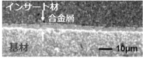
- 4 is a SEM image of a cross section in the thickness direction of the sputtering target of Example 1.
- FIG. 4 is a SEM image of a cross section in the thickness direction of the sputtering target of Example 2.
- FIG. 4 is a SEM image of a cross section in the thickness direction of the sputtering target of Comparative Example 1.
- FIG. 4 is a SEM image of a cross section in the thickness direction of the sputtering target of Comparative Example 2.
- FIG. 1 is a SEM image of a cross section in the thickness direction of the sputtering target of Comparative Example 2.
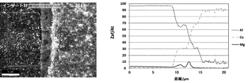
- FIG. 1 is a SEM image showing a scanning range of a cross section in the thickness direction of the sputtering target of Example 1, obtained by EDX LineScan, and a graph showing variations in the content of each element.
- FIG. 10 is an SEM image showing a scanning range of a cross section in the thickness direction of the sputtering target of Example 2 obtained by EDX LineScan, and a graph showing variations in the content of each element.
- FIG. FIG. 10 is an SEM image showing a scanning range of a cross-section in the thickness direction of the sputtering target of Example 3 obtained by EDX LineScan, and a graph showing variations in the content of each element.
- FIG. 10 is a SEM image showing the scanning range of a cross section in the thickness direction of the sputtering target of Comparative Example 1 obtained by EDX LineScan, and a graph showing variations in the content of each element.
- FIG. FIG. 10 is an SEM image showing the scanning range of a cross section in the thickness direction of the sputtering target of Comparative Example 2, which was obtained by EDX LineScan, and a graph showing variations in the content of each element.
- a sputtering target of one embodiment is composed of a plurality of components including a target material and a substrate.
- the plurality of constituent members includes a first constituent member and a second constituent member which are laminated to each other, the first constituent member contains Al, the second constituent member contains Cu, and the first At least one of the component and the second component contains Mg.
- the sputtering target contains Al and Cu between the first component and the second component, and has an alloy layer in contact with the first component and the second component.
- the alloy layer further includes a Mg-containing layer containing 5.0 atomic % or more of Mg in at least part of the alloy layer.
- one constituent member containing Al is referred to as the first constituent member
- the other constituent member containing Cu is called the second constituent member. called.
- the target material and the base material are laminated
- one of the target material and the base material is the first component containing Al
- the other is the second component containing Cu.
- the target material is the first component containing Al
- the insert material is the second component containing Cu.
- the insert material may be the first component containing Al
- the base material may be the second component containing Cu.
- the bonding strength of such a first component member containing Al and the second component member containing Cu is low even if they are directly laminated and joined together. It is believed that this is because Cu and Al form brittle intermetallic compounds (CuAl, CuAl2, etc.) at the interface between the first component and the second component due to interdiffusion. If the bonding strength between the first component and the second component is low, the first component and the second component may separate at the bonding interface due to thermal expansion during sputtering and contraction during cooling.
- an alloy layer containing Al and Cu is provided between the first component member and the second component member and is in contact with the first component member and the second component member, and the alloy layer is At least a part thereof includes an Mg-containing layer containing 5.0 at % or more of Mg in addition to Al and Cu.
- the first component and the second component are firmly joined together.
- the Mg-containing layer in at least a part of the alloy layer the formation of an intermetallic compound of Cu and Al is suppressed by containing Mg together with Cu and Al, and the alloy of Al, Cu, and Mg is stronger. is assumed to be formed.
- the alloy layer containing Al and Cu between the first component and the second component contains Al, Cu and Mg and contains Mg.
- a Mg-containing layer having a portion where the amount is 5.0 at % or more is sufficient.
- a sputtering target in which a target material, an insert material, and a base material are laminated in this order an example in which the first component member is the insert material and the second component member is the base material, or the first configuration
- the member is the base material and the second component is the insert material
- sputtering targets that do not contain insert material can also be targeted.
- the target material has a sputtering surface to be used for sputtering, and generally has a shape such as a disk or other flat plate, or a cylindrical shape.
- the material of this target material is appropriately determined according to the material of the thin film formed on the substrate or the like by sputtering. If the insert material contains Al, the target material should be a material that can be bonded to the Al-containing insert material, such as Ti, Ta, Cu, Cu alloy, W, WSi, Co, Al, etc. can be done.
- the target material typically contains Ti.
- the target material can be made of pure Ti containing mainly Ti.
- a target material made of pure Ti typically has a Ti content of 99.995% by mass or more, but it may be 99.999% by mass or more, or even 99.9995% by mass or more.
- a pure Ti target material may contain at least one impurity selected from the group consisting of Al, Fe, Ni and Cu.
- the target material can be made of a Ti alloy containing Ti and Al.
- the Al content is, for example, 30 at % to 70 at %, and may be about 50 at % as an example.
- the base material has a shape such as a flat plate or a cylindrical shape corresponding to the target material, and is arranged on the back side opposite to the sputtering surface of the target material, and is also called a backing plate or a backing tube.
- the base material is arranged with an insert material, which will be described later, sandwiched between the base material and the target material. That is, the sputtering target of this embodiment is obtained by laminating a target material, an insert material, and a base material in this order.
- the base material is the second constituent member containing Cu.
- the base material is the first component containing Al.
- the insert material is the first component containing Al and the substrate is the second component containing Cu.
- the base material when the base material is the second constituent member, it may be made of pure Cu that mainly contains Cu.
- the substrate if the substrate is the first component, it may be made of pure Al containing mainly Al.
- the base material is the second component, it can be made of a Cu alloy containing Cu and Mg.
- the substrate is the first component, it can be made of an Al alloy containing Al and Mg.
- the Al alloy may contain Si, Mn, Cr, Zn, etc. in addition to Mg.
- the substrate is free of Mg and the insert further contains Mg.
- both the base material and the insert material may contain Mg.
- the base material is preferably made of a Cu alloy or Al alloy containing Mg.
- the Mg content in the substrate is preferably 1.0% by mass to 10.0% by mass, more preferably 3.4% by mass or more.
- the Mg content in the base material is too low, it becomes difficult to form an alloy layer including a Mg-containing layer containing Al, Cu and Mg between the base material and the insert material, resulting in a required bond between the base material and the insert material. There is concern that the bonding strength may not be ensured. If the Mg content in the substrate is too high, the properties originally required for the Mg-containing substrate may be impaired.
- An insert material may be interposed between the target material and the base material.
- This insert material may be provided for the purpose of performing metal-to-metal diffusion bonding in order to improve the bonding strength between the target material and the base material.
- the insert material has a function of, for example, alleviating warpage of the sputtering target and absorbing strain during sputtering.
- the insert material is the first component and contains Al, or the base material is the first component and contains Cu. If it contains Al, the insert material is the second component and contains Cu.
- the insert material when the insert material is the first component, it may be made of pure Al containing mainly Al.
- the insert material when the insert material is the second component, it may be made of pure Cu containing mainly Cu.
- the insert material is the first component member, it can be made of an Al alloy containing Al and Mg.
- the Al alloy may contain Si, Mn, Cr, Zn, etc. in addition to Mg.
- the insert material is the second component, it can be made of a Cu alloy containing Cu and Mg.
- the insert material is preferably made of an Al alloy or a Cu alloy containing Mg.
- the Mg content in the insert material is preferably 1.0% by mass to 10.0% by mass, more preferably 3.4% by mass or more.
- the Mg content in the insert material is too small, it becomes difficult to form an alloy layer including a Mg-containing layer containing Al, Cu and Mg between the base material and the base material, resulting in a required bond between the base material and the insert material. There is concern that the bonding strength may not be ensured. If the Mg content in the insert material is too high, the properties originally required for the insert material containing Mg may be impaired.
- alloy layer An alloy layer containing at least Al and Cu is present between the first constituent member such as the insert material and the second constituent member such as the base material, and at least part of the alloy layer contains Al, Cu and Mg.
- a Mg-containing layer containing the three elements of The Mg-containing layer contains 5.0 atomic % or more of Mg.
- the Mg-containing layer firmly joins the first component and the second component.
- the alloy layer may include, in addition to the Mg-containing layer, a layer containing Al and Cu but not containing Mg.
- the alloy layer and the Mg-containing layer can be confirmed, and each content of the three elements Amount can be measured.
- the alloy layer is between the first component member and the second component member, Al and Cu, respectively.
- content is 5.0 at % or more in terms of element ratio on the line.
- the alloy layer is between the position on the side of the first component where both Al and Cu are 5.0 at% or more and the position on the side of the second component where both Al and Cu are 5.0 at% or more. be.
- the content of Al or Cu When the content of Al or Cu is confirmed from the alloy layer toward the first component member or the second component member near the boundary between the alloy layer and the first component member or the second component member, the content of Al or Cu does not decrease to less than 5.0 at %, the position where the content converges to a constant value is defined as the boundary position between the alloy layer and the first component or the second component.
- the Mg-containing layer is a portion of the alloy layer containing the three elements Al, Cu, and Mg, and the Mg content is 5.0 at% or more.
- the presence or absence of the Mg-containing layer can also be confirmed by performing a SEM-EDX LineScan along the thickness direction of the cross section along the thickness direction of the sputtering target. Even if there is a portion containing the three elements of Al, Cu and Mg in the alloy layer, if the Mg content is less than 5.0 at% at any point in the portion, that portion is a Mg-containing layer. does not consider
- the SEM-EDX Line Scan conditions are magnification: 1000 to 2000 times, distance between the objective lens and the sample (WD, working distance): 10 mm, scanning distance: 30 ⁇ m to 50 ⁇ m.
- the thickness of the alloy layer is preferably 5 ⁇ m to 20 ⁇ m, more preferably 10 ⁇ m to 15 ⁇ m. If the thickness of the alloy layer is too thin, there is a concern that the Mg-containing layer may not sufficiently improve the bonding strength, resulting in a decrease in bonding strength. On the other hand, if the thickness of the alloy layer is too thick, the bonding strength of the intermetallic compound layer of Cu and Al becomes dominant, and the bonding strength may decrease.
- the above-described thickness of the alloy layer is the thickness direction when performing a SEM-EDX LineScan on a cross section along the thickness direction passing through the center of the sputtering target in the radial direction, Al and Cu on the side of the first component. It means the distance between the position where the content of both is 5.0 at % or more and the position where the content of both Al and Cu is 5.0 at % or more on the second component member side.
- the thickness of the Mg-containing layer is preferably 20% or more of the thickness of the alloy layer. Thereby, the joint strength can be greatly improved.
- the Mg-containing layer is preferably formed over a relatively large area between the first component and the second component.
- the Mg-containing layer is preferably formed at a rate of 50% or more of the entire width of the first component member and the second component member along the direction orthogonal to the thickness direction of the cross section. .
- the width of the first component member and the second component member referred to here is the cross section along the thickness direction, and the width of the overlapping region of the first component member and the second component member in the direction orthogonal to the thickness direction. means length along When the Mg-containing layer is present in such a relatively large proportion in the direction perpendicular to the thickness direction, the bonding strength can be further improved. A part of the region where the first component member and the second component member overlap each other may have a portion where the Mg-containing layer does not exist.
- the alloy layer and the Mg-containing layer are preferably formed by diffusion bonding of the first constituent member and the second constituent member.
- the Al content in the alloy layer may be lower in the portion in contact with the second component than in the portion in contact with the first component.
- the Cu content may be less in the portion in contact with the first component than in the portion in contact with the second component.
- the bonding strength between the insert material (first component) and the base material (second component) is more preferably 5 kgf/mm 2 or more, more preferably 10 kgf/mm 2 . If the bonding strength between the insert material and the base material is too low, thermal expansion occurs during sputtering, and shrinkage during cooling may cause separation at the bonding interface via the alloy layer. Although there is no particular problem due to excessively high bonding strength, it may be 15 kgf/mm 2 or less.
- the bonding strength between the insert material and the base material is measured as follows. First, from a sputtering target comprising a target material, an insert material and a base material, a sample is taken in the thickness direction of the target material, the insert material and the base material. In the sputtering target 1 having a circular planar view as shown in FIG. A total of 7 points, ie, 3 points in the center in the radial direction between the points, are set as sample collection points Ps. After that, each sample is subjected to a uniaxial tensile test along the thickness direction using a tensile tester. Then, the strength when the portion corresponding to the insert material and the portion corresponding to the base material in the sample are separated is measured. Let the average value of the strength in each sample be the bonding strength.
- a sputtering target as described above can be manufactured, for example, as described below.
- a plurality of constituent members including a first constituent member and a second constituent member are prepared.
- the first component contains Al
- the second component contains Cu
- at least one of the first component and the second component is made of an alloy containing Mg.
- the target material, the insert material, and the base material described above are prepared respectively.
- one of the insert material and the base material is used as the above-described first component member, and the other is used as the above-described second component member.
- the insert material is the first constituent member containing Al, and the base material is the second constituent member containing Cu.
- the base material does not contain Mg, and the insert material further contains Mg.
- the insert material is an Al alloy containing Mg.
- the target material may contain Ti, for example.
- a bonding step is performed in which a plurality of constituent members including the first constituent member and the second constituent member are laminated and joined by applying pressure.
- the target material, the insert material, and the base material are laminated in this order, and in the laminated state, they are pressed in the thickness direction and joined.
- the Mg diffuses from the first component and/or the second component containing Mg to the interface between the first component and the second component, and the first component and/or the second component Al and Cu contained in the two components also diffuse at the interface.
- an alloy layer containing at least Al and Cu is formed at the interface between the insert material and the base material, and a Mg-containing layer containing 5.0 at% or more of Mg is formed in the alloy layer.
- the Mg-containing layer containing the three elements Al, Cu, and Mg in the alloy layer has high strength, the formation of the Mg-containing layer at the interface between the first component and the second component reduces the first The component and the second component are firmly joined together.
- the insert material which is either the first component member or the second component member, and the base material, which is the other, are firmly joined.
- the bonding process can be performed by hot isostatic pressing (HIP), hot pressing or cold isostatic pressing (CIP) and various other methods, but hot isostatic pressing is Since isotropic pressure (hydrostatic pressure) is applied while heating at a relatively high temperature, the entire interface can be effectively diffusion-bonded.
- HIP hot isostatic pressing
- CIP cold isostatic pressing
- hot isostatic pressing is Since isotropic pressure (hydrostatic pressure) is applied while heating at a relatively high temperature, the entire interface can be effectively diffusion-bonded.
- a sputtering target is obtained in which the target material, insert material, and base material are laminated in this order.
- an alloy layer including a Mg-containing layer containing Al, Cu and Mg is formed at least partially between the insert material and the base material, so the insert material and the base material are required. It is joined with the strength of
- a target material made of pure Ti, an insert material, and a base material were prepared.
- the substrate was made of a Cu—Ni—Si alloy containing 1.8 to 3.0% by mass of Ni, 0.4 to 0.8% by mass of Si, and the balance being Cu.
- an insert material it contains about 4.0 to 4.9% by mass of Mg, about 0.05 to 0.25% by mass of Cr, and about 0.4 to 1.0% by mass of Mn, and the balance is An Mg-based Al alloy containing Al was prepared. Then, the target material, the insert material and the base material were laminated in this order, and hot isostatic pressing (HIP) was performed. A sputtering target was thus manufactured.
- HIP hot isostatic pressing
- Example 2 the insert material is made of Mg-based Al alloy containing about 2.2 to 2.8% by mass of Mg, 0.15 to 0.35% by mass of Cr, and the balance being Al.
- a sputtering target was produced in the same manner as in Example 1, except that
- Example 3 a sputtering target was manufactured in the same manner as in Example 1, except that the HIP temperature was increased and the time was increased.
- Comparative Example 1 a sputtering target was manufactured in the same manner as in Example 1, except that pure Al made mainly of Al was used as the insert material.
- Comparative Example 2 as the insert material, about 3.5 to 4.5% by mass of Cu, about 0.4 to 0.8% by mass of Mg, about 0.2 to 0.8% by mass of Si, and about 0.2 to 0.8% by mass of Mn.
- a sputtering target was produced in the same manner as in Example 1, except that a Cu-based Al alloy containing 0.4 to 0.8% by mass and the balance being Al was used.
- LineScan by EDX was performed on the cross section in the thickness direction of each of the sputtering targets of Examples 1 to 3 and Comparative Examples 1 and 2. This LineScan was performed on a sample taken from a position of 1/2R (a half position of the radius R, a position of the center of the radius) of the cross section along the thickness direction passing through the center of the sputtering target in the radial direction. The results are shown in FIGS. 6-10. In the graphs shown in FIGS. 6 to 10, the horizontal axis is the number of measurement points, and the vertical axis is the element ratio (at %).
- the Mg-containing layer containing Al, Cu and Mg and at least a portion of which has a Mg content of 5.0 at% or more is included in the alloy layer. known to exist.
- the thickness of the alloy layer was about 10 ⁇ m, and the thickness of the Mg-containing layer was about 4 ⁇ m.
- the thickness of the alloy layer was about 7.63 ⁇ m, and the thickness of the Mg-containing layer was about 1.55 ⁇ m.
- the thickness of the alloy layer was about 15 ⁇ m, and the thickness of the Mg-containing layer was about 7 ⁇ m.
- the thickness of the Mg-containing layer was 20% or more of the thickness of the alloy layer.
- Example 2 (FIG. 7), the Al content in the alloy layer on the substrate side did not decrease to less than 5.0 at%, but the Al content converged to a constant value (about 10 at%). , and the position where the convergence starts is recognized as the boundary position between the alloy layer and the base material.
- At least part of the alloy layer between the first component and the second component such as the insert material and the base material contains Al, Cu and Mg, and contains Mg containing 5.0 at% or more of Mg. It has been found that the formation of the layers allows the first component member and the second component member to be firmly joined together.
Landscapes
- Chemical & Material Sciences (AREA)
- Engineering & Computer Science (AREA)
- Mechanical Engineering (AREA)
- Materials Engineering (AREA)
- Metallurgy (AREA)
- Organic Chemistry (AREA)
- Physics & Mathematics (AREA)
- Chemical Kinetics & Catalysis (AREA)
- Thermal Sciences (AREA)
- Crystallography & Structural Chemistry (AREA)
- Plasma & Fusion (AREA)
- Analytical Chemistry (AREA)
- Manufacturing & Machinery (AREA)
- Physical Vapour Deposition (AREA)
Priority Applications (6)
| Application Number | Priority Date | Filing Date | Title |
|---|---|---|---|
| KR1020237004384A KR102870278B1 (ko) | 2021-08-11 | 2022-06-10 | 스퍼터링 타깃 및 스퍼터링 타깃의 제조 방법 |
| IL301507A IL301507A (en) | 2021-08-11 | 2022-06-10 | A splash target and a method for producing a splash target |
| US18/026,437 US12234544B2 (en) | 2021-08-11 | 2022-06-10 | Sputtering target and method for producing sputtering target |
| CN202280006272.5A CN116261605B (zh) | 2021-08-11 | 2022-06-10 | 溅射靶及溅射靶的制造方法 |
| JP2023501674A JP7551893B2 (ja) | 2021-08-11 | 2022-06-10 | スパッタリングターゲット及び、スパッタリングターゲットの製造方法 |
| EP22855731.0A EP4386108A4 (en) | 2021-08-11 | 2022-06-10 | Sputtering target and method for producing sputtering target |
Applications Claiming Priority (2)
| Application Number | Priority Date | Filing Date | Title |
|---|---|---|---|
| JP2021131384 | 2021-08-11 | ||
| JP2021-131384 | 2021-08-11 |
Publications (1)
| Publication Number | Publication Date |
|---|---|
| WO2023017667A1 true WO2023017667A1 (ja) | 2023-02-16 |
Family
ID=85199733
Family Applications (1)
| Application Number | Title | Priority Date | Filing Date |
|---|---|---|---|
| PCT/JP2022/023495 Ceased WO2023017667A1 (ja) | 2021-08-11 | 2022-06-10 | スパッタリングターゲット及び、スパッタリングターゲットの製造方法 |
Country Status (8)
| Country | Link |
|---|---|
| US (1) | US12234544B2 (https=) |
| EP (1) | EP4386108A4 (https=) |
| JP (1) | JP7551893B2 (https=) |
| KR (1) | KR102870278B1 (https=) |
| CN (1) | CN116261605B (https=) |
| IL (1) | IL301507A (https=) |
| TW (1) | TWI841980B (https=) |
| WO (1) | WO2023017667A1 (https=) |
Families Citing this family (1)
| Publication number | Priority date | Publication date | Assignee | Title |
|---|---|---|---|---|
| KR102901902B1 (ko) * | 2023-05-26 | 2025-12-19 | 제엠제코(주) | 금속 클립 구조체 및 이를 구비한 반도체 패키지 |
Citations (8)
| Publication number | Priority date | Publication date | Assignee | Title |
|---|---|---|---|---|
| JPH06172993A (ja) * | 1992-12-07 | 1994-06-21 | Japan Energy Corp | 拡散接合されたスパッタリングターゲット組立体及びその製造方法 |
| JPH1177365A (ja) * | 1997-07-18 | 1999-03-23 | Kobe Steel Ltd | TiAl系金属間化合物とTi基合金を接合するためのインサート材およびその接合方法、並びに接合体 |
| US5993621A (en) | 1997-07-11 | 1999-11-30 | Johnson Matthey Electronics, Inc. | Titanium sputtering target |
| WO2001038598A1 (fr) | 1999-11-22 | 2001-05-31 | Nikko Materials Company, Limited | Cible en titane pour la pulverisation cathodique |
| JP2002105635A (ja) * | 2000-10-02 | 2002-04-10 | Nikko Materials Co Ltd | 高純度コバルトターゲットと銅合金製バッキングプレートとの拡散接合ターゲット組立体及びその製造方法 |
| JP2003500546A (ja) * | 1999-06-02 | 2003-01-07 | ジョンソン・マッセイ・エレクトロニクス・インコーポレーテッド | 銅スパッター用ターゲットアセンブリー及びその製造方法 |
| JP2010235998A (ja) | 2009-03-31 | 2010-10-21 | Nippon Mining & Metals Co Ltd | スパッタリング用チタンターゲット |
| WO2020195030A1 (ja) * | 2019-03-28 | 2020-10-01 | Jx金属株式会社 | スパッタリングターゲット製品及びスパッタリングターゲット製品の再生品を製造する方法 |
Family Cites Families (12)
| Publication number | Priority date | Publication date | Assignee | Title |
|---|---|---|---|---|
| US5693203A (en) | 1992-09-29 | 1997-12-02 | Japan Energy Corporation | Sputtering target assembly having solid-phase bonded interface |
| JP3866320B2 (ja) | 1995-02-09 | 2007-01-10 | 日本碍子株式会社 | 接合体、および接合体の製造方法 |
| JP3829367B2 (ja) * | 1996-08-02 | 2006-10-04 | 東ソー株式会社 | スパッタリングターゲット |
| JPH11236665A (ja) * | 1998-02-20 | 1999-08-31 | Japan Energy Corp | スパッタリングタ−ゲット用バッキングプレ−ト及びスパッタリングタ−ゲット/バッキングプレ−ト組立体 |
| JP2002294437A (ja) * | 2001-04-02 | 2002-10-09 | Mitsubishi Materials Corp | 銅合金スパッタリングターゲット |
| JP2002294440A (ja) * | 2001-04-03 | 2002-10-09 | Sumitomo Chem Co Ltd | スパッタリング用ターゲットとその製造方法 |
| US20090078570A1 (en) * | 2003-08-11 | 2009-03-26 | Wuwen Yi | Target/backing plate constructions, and methods of forming target/backing plate constructions |
| SG189977A1 (en) * | 2010-10-27 | 2013-06-28 | Jx Nippon Mining & Metals Corp | Sputtering target backing plate assembly and method for producing same |
| US10844475B2 (en) | 2015-12-28 | 2020-11-24 | Jx Nippon Mining & Metals Corporation | Method for manufacturing sputtering target |
| JP6271798B2 (ja) | 2016-07-13 | 2018-01-31 | 住友化学株式会社 | スパッタリングターゲットの製造方法 |
| US10900102B2 (en) | 2016-09-30 | 2021-01-26 | Honeywell International Inc. | High strength aluminum alloy backing plate and methods of making |
| CN111989421B (zh) * | 2018-05-21 | 2022-12-06 | 株式会社爱发科 | 溅射靶材及其制造方法 |
-
2022
- 2022-06-10 WO PCT/JP2022/023495 patent/WO2023017667A1/ja not_active Ceased
- 2022-06-10 JP JP2023501674A patent/JP7551893B2/ja active Active
- 2022-06-10 IL IL301507A patent/IL301507A/en unknown
- 2022-06-10 CN CN202280006272.5A patent/CN116261605B/zh active Active
- 2022-06-10 TW TW111121660A patent/TWI841980B/zh active
- 2022-06-10 US US18/026,437 patent/US12234544B2/en active Active
- 2022-06-10 EP EP22855731.0A patent/EP4386108A4/en active Pending
- 2022-06-10 KR KR1020237004384A patent/KR102870278B1/ko active Active
Patent Citations (10)
| Publication number | Priority date | Publication date | Assignee | Title |
|---|---|---|---|---|
| JPH06172993A (ja) * | 1992-12-07 | 1994-06-21 | Japan Energy Corp | 拡散接合されたスパッタリングターゲット組立体及びその製造方法 |
| US5993621A (en) | 1997-07-11 | 1999-11-30 | Johnson Matthey Electronics, Inc. | Titanium sputtering target |
| JP2001509548A (ja) | 1997-07-11 | 2001-07-24 | ジョンソン マッティー エレクトロニクス インコーポレイテッド | チタンスパッタターゲット及びその製造方法 |
| JPH1177365A (ja) * | 1997-07-18 | 1999-03-23 | Kobe Steel Ltd | TiAl系金属間化合物とTi基合金を接合するためのインサート材およびその接合方法、並びに接合体 |
| JP2003500546A (ja) * | 1999-06-02 | 2003-01-07 | ジョンソン・マッセイ・エレクトロニクス・インコーポレーテッド | 銅スパッター用ターゲットアセンブリー及びその製造方法 |
| WO2001038598A1 (fr) | 1999-11-22 | 2001-05-31 | Nikko Materials Company, Limited | Cible en titane pour la pulverisation cathodique |
| US6755948B1 (en) | 1999-11-22 | 2004-06-29 | Nikko Materials Company, Limited | Titanium target for sputtering |
| JP2002105635A (ja) * | 2000-10-02 | 2002-04-10 | Nikko Materials Co Ltd | 高純度コバルトターゲットと銅合金製バッキングプレートとの拡散接合ターゲット組立体及びその製造方法 |
| JP2010235998A (ja) | 2009-03-31 | 2010-10-21 | Nippon Mining & Metals Co Ltd | スパッタリング用チタンターゲット |
| WO2020195030A1 (ja) * | 2019-03-28 | 2020-10-01 | Jx金属株式会社 | スパッタリングターゲット製品及びスパッタリングターゲット製品の再生品を製造する方法 |
Non-Patent Citations (1)
| Title |
|---|
| See also references of EP4386108A4 |
Also Published As
| Publication number | Publication date |
|---|---|
| US20240026525A1 (en) | 2024-01-25 |
| CN116261605A (zh) | 2023-06-13 |
| JPWO2023017667A1 (https=) | 2023-02-16 |
| EP4386108A4 (en) | 2025-06-18 |
| KR102870278B1 (ko) | 2025-10-15 |
| CN116261605B (zh) | 2025-04-25 |
| KR20230035626A (ko) | 2023-03-14 |
| TWI841980B (zh) | 2024-05-11 |
| TW202307238A (zh) | 2023-02-16 |
| IL301507A (en) | 2023-05-01 |
| JP7551893B2 (ja) | 2024-09-17 |
| EP4386108A1 (en) | 2024-06-19 |
| US12234544B2 (en) | 2025-02-25 |
Similar Documents
| Publication | Publication Date | Title |
|---|---|---|
| TWI335850B (en) | Joints and method for forming the same | |
| WO2014046130A1 (ja) | アルミニウム部材と銅部材との接合構造 | |
| Yang et al. | Experimental investigation of the failure mechanism of Cu–Sn intermetallic compounds in SAC solder joints | |
| JP7196193B2 (ja) | 放熱部材 | |
| JP7312825B2 (ja) | ベリリウム銅合金接合体及びその製造方法 | |
| US20170368607A1 (en) | Functionally graded w-cu composite | |
| WO2023017667A1 (ja) | スパッタリングターゲット及び、スパッタリングターゲットの製造方法 | |
| JPS60166165A (ja) | 窒化物系セラミックスと金属との接合方法 | |
| Abouie et al. | Eutectic and solid-state wafer bonding of silicon with gold | |
| WO2010110476A1 (ja) | 接合部材及び接合方法 | |
| CN111682002B (zh) | 散热板 | |
| JP2019143179A (ja) | スパッタリングターゲット | |
| JP2025024187A (ja) | W-Pt-Cu合金 | |
| JP2025144282A (ja) | 金属/セラミックス接合体、ろう材、および、金属/セラミックス接合体の製造方法 | |
| US20250327172A1 (en) | Cobalt-titanium alloy sputtering target assembly and method of making | |
| US20250263828A1 (en) | Molybdenum sputtering target with high transverse rupture strength | |
| JP2013180479A (ja) | 積層体、ヒートシンクおよび積層体の製造方法 | |
| JPH0849069A (ja) | スパッタリング用ターゲットおよびその製造方法 | |
| US20250327171A1 (en) | Cobalt-tantalum alloy sputtering target assembly and method of making | |
| TWI856716B (zh) | 複合靶材及其製法 | |
| US20250122608A1 (en) | Diffusion bonded tungsten containing target to titanium or titanium alloy backing plate | |
| CN120513316A (zh) | 将含钨靶扩散接合到铜合金背板 | |
| JP2025131783A (ja) | 金属/セラミックス接合体、ろう材、金属/セラミックス接合体の製造方法、および、ろう材の製造方法 | |
| TW202600843A (zh) | 鈷鈮合金濺鍍靶材總成及製造方法 | |
| JP2004355922A (ja) | X線管用ターゲットおよびその製造方法 |
Legal Events
| Date | Code | Title | Description |
|---|---|---|---|
| ENP | Entry into the national phase |
Ref document number: 2023501674 Country of ref document: JP Kind code of ref document: A |
|
| ENP | Entry into the national phase |
Ref document number: 20237004384 Country of ref document: KR Kind code of ref document: A |
|
| WWE | Wipo information: entry into national phase |
Ref document number: 18026437 Country of ref document: US |
|
| 121 | Ep: the epo has been informed by wipo that ep was designated in this application |
Ref document number: 22855731 Country of ref document: EP Kind code of ref document: A1 |
|
| NENP | Non-entry into the national phase |
Ref country code: DE |
|
| ENP | Entry into the national phase |
Ref document number: 2022855731 Country of ref document: EP Effective date: 20240311 |
|
| WWG | Wipo information: grant in national office |
Ref document number: 18026437 Country of ref document: US |
|
| WWG | Wipo information: grant in national office |
Ref document number: 202280006272.5 Country of ref document: CN |