WO2023007550A1 - 車高調整機能付き緩衝器 - Google Patents
車高調整機能付き緩衝器 Download PDFInfo
- Publication number
- WO2023007550A1 WO2023007550A1 PCT/JP2021/027556 JP2021027556W WO2023007550A1 WO 2023007550 A1 WO2023007550 A1 WO 2023007550A1 JP 2021027556 W JP2021027556 W JP 2021027556W WO 2023007550 A1 WO2023007550 A1 WO 2023007550A1
- Authority
- WO
- WIPO (PCT)
- Prior art keywords
- shock absorber
- passage
- vehicle height
- height adjustment
- side chamber
- Prior art date
- Legal status (The legal status is an assumption and is not a legal conclusion. Google has not performed a legal analysis and makes no representation as to the accuracy of the status listed.)
- Ceased
Links
Images




Classifications
-
- B—PERFORMING OPERATIONS; TRANSPORTING
- B60—VEHICLES IN GENERAL
- B60G—VEHICLE SUSPENSION ARRANGEMENTS
- B60G17/00—Resilient suspensions having means for adjusting the spring or vibration-damper characteristics, for regulating the distance between a supporting surface and a sprung part of vehicle or for locking suspension during use to meet varying vehicular or surface conditions, e.g. due to speed or load
- B60G17/015—Resilient suspensions having means for adjusting the spring or vibration-damper characteristics, for regulating the distance between a supporting surface and a sprung part of vehicle or for locking suspension during use to meet varying vehicular or surface conditions, e.g. due to speed or load the regulating means comprising electric or electronic elements
-
- B—PERFORMING OPERATIONS; TRANSPORTING
- B60—VEHICLES IN GENERAL
- B60G—VEHICLE SUSPENSION ARRANGEMENTS
- B60G15/00—Resilient suspensions characterised by arrangement, location or type of combined spring and vibration damper, e.g. telescopic type
- B60G15/02—Resilient suspensions characterised by arrangement, location or type of combined spring and vibration damper, e.g. telescopic type having mechanical spring
- B60G15/06—Resilient suspensions characterised by arrangement, location or type of combined spring and vibration damper, e.g. telescopic type having mechanical spring and fluid damper
- B60G15/062—Resilient suspensions characterised by arrangement, location or type of combined spring and vibration damper, e.g. telescopic type having mechanical spring and fluid damper the spring being arranged around the damper
-
- B—PERFORMING OPERATIONS; TRANSPORTING
- B60—VEHICLES IN GENERAL
- B60G—VEHICLE SUSPENSION ARRANGEMENTS
- B60G17/00—Resilient suspensions having means for adjusting the spring or vibration-damper characteristics, for regulating the distance between a supporting surface and a sprung part of vehicle or for locking suspension during use to meet varying vehicular or surface conditions, e.g. due to speed or load
- B60G17/02—Spring characteristics, e.g. mechanical springs and mechanical adjusting means
- B60G17/027—Mechanical springs regulated by fluid means
- B60G17/0272—Mechanical springs regulated by fluid means the mechanical spring being a coil spring
-
- B—PERFORMING OPERATIONS; TRANSPORTING
- B60—VEHICLES IN GENERAL
- B60G—VEHICLE SUSPENSION ARRANGEMENTS
- B60G17/00—Resilient suspensions having means for adjusting the spring or vibration-damper characteristics, for regulating the distance between a supporting surface and a sprung part of vehicle or for locking suspension during use to meet varying vehicular or surface conditions, e.g. due to speed or load
- B60G17/02—Spring characteristics, e.g. mechanical springs and mechanical adjusting means
- B60G17/04—Spring characteristics, e.g. mechanical springs and mechanical adjusting means fluid spring characteristics
- B60G17/056—Regulating distributors or valves for hydropneumatic systems
- B60G17/0565—Height adjusting valves
-
- B—PERFORMING OPERATIONS; TRANSPORTING
- B60—VEHICLES IN GENERAL
- B60G—VEHICLE SUSPENSION ARRANGEMENTS
- B60G17/00—Resilient suspensions having means for adjusting the spring or vibration-damper characteristics, for regulating the distance between a supporting surface and a sprung part of vehicle or for locking suspension during use to meet varying vehicular or surface conditions, e.g. due to speed or load
- B60G17/06—Characteristics of dampers, e.g. mechanical dampers
- B60G17/08—Characteristics of fluid dampers
-
- B—PERFORMING OPERATIONS; TRANSPORTING
- B60—VEHICLES IN GENERAL
- B60G—VEHICLE SUSPENSION ARRANGEMENTS
- B60G2202/00—Indexing codes relating to the type of spring, damper or actuator
- B60G2202/30—Spring/Damper and/or actuator Units
- B60G2202/31—Spring/Damper and/or actuator Units with the spring arranged around the damper, e.g. MacPherson strut
- B60G2202/312—The spring being a wound spring
-
- B—PERFORMING OPERATIONS; TRANSPORTING
- B60—VEHICLES IN GENERAL
- B60G—VEHICLE SUSPENSION ARRANGEMENTS
- B60G2202/00—Indexing codes relating to the type of spring, damper or actuator
- B60G2202/40—Type of actuator
- B60G2202/41—Fluid actuator
- B60G2202/416—Fluid actuator using a pump, e.g. in the line connecting the lower chamber to the upper chamber of the actuator
-
- B—PERFORMING OPERATIONS; TRANSPORTING
- B60—VEHICLES IN GENERAL
- B60G—VEHICLE SUSPENSION ARRANGEMENTS
- B60G2300/00—Indexing codes relating to the type of vehicle
- B60G2300/12—Cycles; Motorcycles
-
- B—PERFORMING OPERATIONS; TRANSPORTING
- B60—VEHICLES IN GENERAL
- B60G—VEHICLE SUSPENSION ARRANGEMENTS
- B60G2500/00—Indexing codes relating to the regulated action or device
- B60G2500/30—Height or ground clearance
-
- B—PERFORMING OPERATIONS; TRANSPORTING
- B60—VEHICLES IN GENERAL
- B60G—VEHICLE SUSPENSION ARRANGEMENTS
- B60G2800/00—Indexing codes relating to the type of movement or to the condition of the vehicle and to the end result to be achieved by the control action
- B60G2800/90—System Controller type
- B60G2800/91—Suspension Control
- B60G2800/914—Height Control System
-
- B—PERFORMING OPERATIONS; TRANSPORTING
- B62—LAND VEHICLES FOR TRAVELLING OTHERWISE THAN ON RAILS
- B62K—CYCLES; CYCLE FRAMES; CYCLE STEERING DEVICES; RIDER-OPERATED TERMINAL CONTROLS SPECIALLY ADAPTED FOR CYCLES; CYCLE AXLE SUSPENSIONS; CYCLE SIDECARS, FORECARS, OR THE LIKE
- B62K25/00—Axle suspensions
- B62K25/04—Axle suspensions for mounting axles resiliently on cycle frame or fork
- B62K2025/045—Suspensions with ride-height adjustment
-
- F—MECHANICAL ENGINEERING; LIGHTING; HEATING; WEAPONS; BLASTING
- F16—ENGINEERING ELEMENTS AND UNITS; GENERAL MEASURES FOR PRODUCING AND MAINTAINING EFFECTIVE FUNCTIONING OF MACHINES OR INSTALLATIONS; THERMAL INSULATION IN GENERAL
- F16F—SPRINGS; SHOCK-ABSORBERS; MEANS FOR DAMPING VIBRATION
- F16F9/00—Springs, vibration-dampers, shock-absorbers, or similarly-constructed movement-dampers using a fluid or the equivalent as damping medium
- F16F9/10—Springs, vibration-dampers, shock-absorbers, or similarly-constructed movement-dampers using a fluid or the equivalent as damping medium using liquid only; using a fluid of which the nature is immaterial
- F16F9/14—Devices with one or more members, e.g. pistons, vanes, moving to and fro in chambers and using throttling effect
- F16F9/16—Devices with one or more members, e.g. pistons, vanes, moving to and fro in chambers and using throttling effect involving only straight-line movement of the effective parts
- F16F9/18—Devices with one or more members, e.g. pistons, vanes, moving to and fro in chambers and using throttling effect involving only straight-line movement of the effective parts with a closed cylinder and a piston separating two or more working spaces therein
- F16F9/185—Bitubular units
-
- F—MECHANICAL ENGINEERING; LIGHTING; HEATING; WEAPONS; BLASTING
- F16—ENGINEERING ELEMENTS AND UNITS; GENERAL MEASURES FOR PRODUCING AND MAINTAINING EFFECTIVE FUNCTIONING OF MACHINES OR INSTALLATIONS; THERMAL INSULATION IN GENERAL
- F16F—SPRINGS; SHOCK-ABSORBERS; MEANS FOR DAMPING VIBRATION
- F16F9/00—Springs, vibration-dampers, shock-absorbers, or similarly-constructed movement-dampers using a fluid or the equivalent as damping medium
- F16F9/32—Details
Definitions
- the present invention relates to a shock absorber with a vehicle height adjustment function.
- a shock absorber with a vehicle height adjustment function of this type includes an outer shell and a piston rod inserted into the outer shell so as to be axially movable.
- a damper body that generates a damping force when the piston rod moves relative to the shell, an annular spring bearing that is slidably attached to the outer periphery of the outer shell, a rod-side spring bearing that is attached to the tip of the piston rod,
- a suspension spring interposed between the spring bearing and the rod-side spring bearing to urge the shock absorber body in the extension direction, and a vehicle height adjustment device attached to the outer periphery of the outer shell to axially drive the spring bearing. and is interposed between the motorcycle body and the swing arm.
- the vehicle height adjustment device includes a hydraulic jack that is attached to the outer periphery of the outer shell and drives the spring bearing in the axial direction, a pump that supplies and discharges pressure oil to and from the hydraulic jack via a hose, and hydraulic oil. It has a storage tank.
- the hydraulic jack contracts and moves the spring support along the outer circumference of the outer shell to the opposite side of the piston rod. move.
- the hydraulic jack extends to move the spring bearing along the outer circumference of the outer shell toward the piston rod.
- the shock absorber with a vehicle height adjustment function can adjust the vehicle height of the motorcycle by changing the position of the spring bearing with respect to the outer shell by driving the hydraulic jack. It is possible to improve the foot grounding of the person.
- shock absorbers with a height adjustment function adjust the vehicle height using a height adjustment device attached to the outer shell of the shock absorber body, and the shock absorber body is equipped with a separate reservoir.
- the vehicle height adjustment device is equipped with a hydraulic jack and a tank, it is large as a whole, and there is a problem in mounting it on a vehicle.
- an object of the present invention is to provide a shock absorber with a vehicle height adjustment function that is small even if it is equipped with the vehicle height adjustment function.
- the shock absorber with a vehicle height adjustment function in the problem solving means of the present invention comprises a cylinder filled with liquid, and a compression side chamber and a compression side chamber which are movably inserted into the cylinder and inserted into the cylinder. a piston rod that is movably inserted into a cylinder and connected to the piston; a suspension spring that biases the shock absorber body in the extension direction; and a reservoir that stores liquid.
- a damper circuit that is connected to the expansion side chamber, the compression side chamber and the reservoir and generates a damping force in the shock absorber body when the shock absorber body expands and contracts
- a pump that can suck and discharge liquid from the reservoir, the shock absorber body and the damper circuit and the pump, and can be switched between a damper mode in which the shock absorber body is connected to the damper circuit to generate damping force in the shock absorber body, and a vehicle height adjustment mode in which the shock absorber body is connected to the pump. and a switching valve.
- the damper circuit and the pump can be selectively activated by the switching valve, so when the shock absorber main body generates a damping force, excess or deficiency is generated in the cylinder.
- the reservoir that is used to supply and discharge the liquid to be used can be used as a tank that stores the liquid to be supplied into the shock absorber body when the vehicle height is adjusted.
- the pump can be driven to supply liquid into the shock absorber body to extend or contract the shock absorber body.
- a jack for driving the spring bearing is also unnecessary. Therefore, according to the shock absorber with a vehicle height adjustment function, it is possible to reduce the size even if the vehicle height adjustment function is provided.
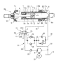
- FIG. 1 is a diagram showing a shock absorber with a vehicle height adjustment function according to the first embodiment.
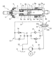
- FIG. 2 is a diagram showing a shock absorber with a vehicle height adjustment function in a first modified example of the first embodiment.
- FIG. 3 is a diagram showing a shock absorber with a vehicle height adjustment function in a second modification of the first embodiment.
- FIG. 4 is a diagram showing a shock absorber with a vehicle height adjustment function according to the second embodiment.
- FIG. 5 is a diagram showing a shock absorber with a vehicle height adjustment function in a first modified example of the second embodiment.
- FIG. 6 is a diagram showing a shock absorber with a vehicle height adjustment function in a second modified example of the second embodiment.
- FIG. 1 is a diagram showing a shock absorber with a vehicle height adjustment function according to the first embodiment.
- FIG. 2 is a diagram showing a shock absorber with a vehicle height adjustment function in a first modified example of the first embodiment.
- FIG. 3 is a
- FIG. 7 is a diagram showing a shock absorber with a vehicle height adjustment function according to the third embodiment.
- FIG. 8 is a diagram showing the structure of a cap in a concrete example of the shock absorber with a vehicle height adjustment function according to the third embodiment.
- FIG. 9 is a vertical cross-sectional view of a specific example of the shock absorber with a vehicle height adjustment function according to the third embodiment.
- the shock absorber D1 with a vehicle height adjustment function in the first embodiment includes a shock absorber body 1, a suspension spring S that biases the shock absorber body 1 in the extension direction, and a liquid reservoir. It has a reservoir R, a damper circuit C1, a pump P, and a switching valve V1, and is used by being interposed between the vehicle body and the axle (not shown).
- the vehicle in which the shock absorber with vehicle height adjustment function of each embodiment is used is not limited to a motorcycle, and may be an automobile or other vehicle.
- the shock absorber body 1 in the present embodiment includes a cylinder 2 filled with liquid, a piston 3 that is movably inserted into the cylinder 2 and partitions the inside of the cylinder 2 into an expansion side chamber R1 and a compression side chamber R2, and a cylinder A cylindrical outer that forms an annular gap 6 that covers the outer periphery of the cylinder 2 and communicates with the expansion side chamber R1 between the piston rod 4 that is movably inserted into the cylinder 2 and connected to the piston 3.
- a shell 5 is provided.
- the cylinder 2 has a cylindrical shape, and as described above, the piston 3 is inserted therein so as to be axially movable with respect to the cylinder 2.
- Pressure-side chambers R2 are respectively partitioned on the right side in FIG.
- hydraulic fluid for example, is filled in the expansion side chamber R1 and the compression side chamber R2 as hydraulic fluid.
- working liquid other than working oil, for example, liquid such as water or aqueous solution may be used.
- a flange 2b is provided at the right end of the cylinder 2 in FIG.
- a piston rod 4 connected to the piston 3 is inserted into the cylinder 2 so as to be axially movable. Furthermore, the cylinder 2 is accommodated in a cylindrical outer shell 5 arranged on the outer peripheral side, and an annular gap 6 is formed between the cylinder 2 and the outer shell 5 .
- An annular rod guide 7 is attached to the left end of the cylinder 2 and the outer shell 5 in FIG.
- the rod guide 7 includes a seal ring 7a that slides on the outer periphery of the piston rod 4, and a cylindrical bushing 7b that slides on the outer periphery of the piston rod 4. 2 guides axial movement.
- a cap 8 that closes the bottom ends of the cylinder 2 and the outer shell 5 is attached to the bottom end of the cylinder 2 and the outer shell 5, which is the right end in FIG. Openings at both ends of the cylinder 2 and the outer shell 5 are closed by rod guides 7 and caps 8, and both ends of the annular gap 6 in the cylinder 2 and between the cylinder 2 and the outer shell 5 are closed. .
- the cap 8 has a cylindrical shape with a bottom, and the outer circumference of the flange 2b of the cylinder 2 is fitted to the inner circumference.
- a screw portion 5b provided on the outer periphery of the outer shell 5 is screwed into the inner periphery of the cap 8, and the flange 2b of the cylinder 2 is held between the outer shell 5 and the bottom of the cap 8, and the cylinder 2 is held by the cap 8.
- the structure for fastening the cylinder 2 and the outer shell 5 to the cap 8 described above is an example, and other fastening structures may be employed.
- the cap 8 is also provided with a port 8a that opens from the side and communicates with the annular gap 6, and a port 8b that similarly opens from the side and communicates with the compression side chamber R2. Ports 8a and 8b are each connected to a damper circuit C1.
- a hole 2 a is provided in the vicinity of the head end of the cylinder 2 to communicate the expansion side chamber R 1 with the annular gap 6 . Therefore, the expansion side chamber R1 is connected to the damper circuit C1 via the annular gap 6 and the port 8a, and the compression side chamber R2 is connected to the damper circuit C1 via the port 8b.
- the cap 8 is provided with a bottom-side spring bearing 8c which is an annular stepped portion provided on the outer periphery closer to the cylinder than the openings of the ports 8a and 8b.
- the piston 3 is provided with a relief passage 9 that communicates the expansion side chamber R1 and the compression side chamber R2, and a relief valve 10 that opens and closes the relief passage 9.
- the relief valve 10 opens when the pressure in the expansion-side chamber R1 exceeds the pressure in the compression-side chamber R2 and the differential pressure between the two reaches the valve opening pressure, allowing only the flow of hydraulic oil from the expansion-side chamber R1 to the compression-side chamber R2. do.
- a bracket 11 for mounting the piston rod 4 to the vehicle is attached to the left end of the piston rod 4 in FIG. there is Note that the head-side spring bearing 12 may be directly attached to the piston rod 4 .
- a suspension spring S is interposed between the head-side spring bearing 12 and the bottom-side spring bearing 8c formed on the cap 8.
- the suspension spring S is interposed in a compressed state between the head-side spring bearing 12 and the bottom-side spring bearing 8c, and always biases the piston rod 4 in the direction of protruding outward from the cylinder 2. As shown in FIG. That is, the suspension spring S biases the shock absorber main body 1 in the extension direction.
- the inside of the reservoir R is partitioned by a diaphragm into a liquid chamber filled with hydraulic oil and an air chamber filled with gas, although not shown.
- the hydraulic oil in the liquid chamber is an accumulator pressurized by the pressure of the gas in the air chamber.
- the reservoir R may be one that only stores hydraulic fluid and does not pressurize the fluid chamber.
- the partition between the liquid chamber and the air chamber in the reservoir R may be a free piston, a bellows, or the like instead of the diaphragm.
- the damper circuit C1 includes a first passage 13 having one end connected to the expansion side chamber R1, a second passage 14 connecting the other end of the first passage 13 to the reservoir R, and the first passage 13 and the second passage 14.
- a third passage 15 that connects the first connection point J1, which is a connection point, to the compression side chamber R2, and a third passage 15 that is provided in the first passage 13 and provides resistance to the flow of hydraulic oil from the expansion side chamber R1 toward the first connection point J1.
- a first extension side damping valve 16 and a first extension side check valve provided in the first passage 13 in parallel with the first extension side damping valve to allow only the flow of hydraulic oil from the first connection point J1 toward the extension side chamber R1.
- valve 17 a valve 17; a first compression damping valve 18 provided in the second passage 14 to provide resistance to the flow of hydraulic oil from the first connection point J1 to the reservoir R; A first pressure side check valve 19 is provided in parallel and allows only the flow of hydraulic fluid from the reservoir R toward the first connection point J1.
- the first passage 13 has one end connected to the expansion side chamber R1 and the other end connected to the second passage 14 .
- the second passage 14 is connected to the first passage 13 at one end and to the reservoir R at the other end.
- the first passage 13 and the second passage 14 are connected in series, and the growth side chamber R1 is connected to the reservoir R via the first passage 13 and the second passage 14.
- the third passage 15 has one end connected to the pressure side chamber R2 and the other end connected to the first connection point J1 between the first passage 13 and the second passage 14 . Therefore, the growth side chamber R1 is connected to the compression side chamber R2 through the first passage 13 and the third passage 15, and the compression side chamber R2 is connected to the reservoir R through the third passage 15 and the second passage 14.
- the first extension side damping valve 16 allows only the flow of hydraulic oil passing through the first passage 13 from the extension side chamber R1 toward the first connection point J1. It is a damping valve that gives resistance to the flow of hydraulic oil that passes through it, and is, for example, a leaf valve or a poppet valve.
- the first rebound damping valve 16 may be a valve such as an orifice or a choke that allows bidirectional flow.
- the first expansion side check valve 17 is provided in the first passage 13 in parallel with the first expansion side damping valve, and passes through the first passage 13 from the first connection point J1 toward the expansion side chamber R1. Permits only the flow of hydraulic fluid and blocks the reverse flow of hydraulic fluid.
- the first compression side damping valve 18 only allows hydraulic oil to flow through the second passage 14 from the first connection point J1 toward the reservoir R. It is a damping valve that provides resistance to the flow of hydraulic oil passing through it, and is, for example, a leaf valve or a poppet valve.
- the first compression damping valve 18 may be a valve that allows bidirectional flow, such as an orifice or choke.
- the first pressure side check valve 19 is provided in the second passage 14 in parallel with the first pressure side damping valve 18, and the hydraulic oil passing through the second passage 14 from the reservoir R toward the first connection point J1 is Only allow the flow of hydraulic oil in the opposite direction and prevent the flow in the opposite direction.
- the pump P is provided in a pump passage 20, one end of which is connected to the reservoir R and the other end of which communicates with the switching valve V1. It is a one-way pump that discharges toward V1.
- the pump P is a gear pump, it may be a piston pump, a screw pump, or any other type of pump.
- the pump passage 20 is provided with a pump passage check valve 22 that allows only the flow of hydraulic oil from the pump P toward the switching valve V1. Hydraulic oil is prevented from flowing backward.
- the switching valve V1 is a 3-port, 2-position electromagnetic switching valve having three ports a, t, and p. 16 and the first expansion-side check valve 17 on the expansion-side chamber side, and the port p is connected to the other end of the pump passage 20 .
- the switching valve V1 has a first position 23a that connects the port a and the port t to communicate the first passage 13 and closes the port p to block the other end of the pump passage 20;
- a valve body 23 having a second position 23b that closes the first passage 13 by closing the first passage 13 and connects the port a and the port p to communicate the pump passage 20 and the expansion side chamber R1, and the first position It has a spring 24 for biasing the valve body 23 to take the position 23a, and a solenoid 25 for switching the valve body 23 to the second position 23b against the biasing force of the spring 24 when energized.
- the switching valve V1 when the switching valve V1 takes the first position 23a without energizing the solenoid 25, the pump passage 20 is blocked and the shock absorber main body 1 is connected to the damper circuit C1 through the first passage 13, thereby C1 becomes effective, and the shock absorber D1 with a vehicle height adjustment function enters the damper mode.
- the solenoid 25 is energized and the switching valve V1 takes the second position 23b, the first passage 13 is blocked, the pump passage 20 is connected to the expansion side chamber R1, and the pump P becomes effective, thereby enabling the vehicle height adjustment function.
- the attached shock absorber D1 is in the vehicle height adjustment mode.
- the switching valve V1 can select and switch the damper D1 with the vehicle height adjustment function between the damper mode in which only the damper circuit C1 is activated and the vehicle height adjustment mode in which the pump P is activated.
- the shock absorber D1 with the vehicle height adjustment function of the first embodiment is configured as described above, and its operation will be explained below. First, the operation when the switching valve V1 selects the first position 23a and the damper D1 with the vehicle height adjustment function is set to the damper mode will be described.
- the switching valve V1 connects the expansion side chamber R1 to the damper circuit C1 via the first passage 13, and connects the pressure side chamber R2 and the reservoir R via the damper circuit C1, while the pump passage 20 is connected to The connection between the expansion side chamber R1 and the pump P is cut off.
- This deficient hydraulic oil passes through the first pressure-side check valve 19 in the second passage 14 from the reservoir R, and is supplied to the pressure-side chamber R2 via the third passage 15 .
- the first extension damping valve 16 gives resistance to the flow of hydraulic oil moving from the extension side chamber R1 to the compression side chamber R2, so the pressure in the extension side chamber R1 increases, the pressure in the compression side chamber R2 becomes substantially equal to the pressure in the reservoir R, so the shock absorber D1 with a vehicle height adjustment function generates a rebound damping force that prevents the shock absorber main body 1 from extending.
- the excess hydraulic oil is discharged to the reservoir R via the first compression damping valve 18 in the second passage 14 .
- the first compression damping valve 18 gives resistance to the flow of hydraulic fluid moving from the compression side chamber R2 to the reservoir R, so that the expansion chamber R1 and the compression chamber R2 The internal pressure rises and becomes approximately equal.
- the shock absorber D1 with a vehicle height adjustment function is a shock absorber A compression side damping force is generated to prevent contraction of the main body 1 .
- the shock absorber D1 with a vehicle height adjustment function adopts the damper mode
- the shock absorber main body 1 is expanded and contracted by an external force
- the shock absorber D1 with a vehicle height adjustment function exerts a damping force that prevents the shock absorber main body 1 from expanding and contracting. Occur.
- the operation when the switching valve V1 selects the second position 23b and the shock absorber D1 with the vehicle height adjustment function is set to the vehicle height adjustment mode will be described.
- the switching valve V1 takes the second position 23b the pump passage 20 is connected to the expansion side chamber R1, the first passage 13 is blocked, and the portion of the first passage 13 from the switching valve V1 to the first connection point J1 is closed. , the hydraulic oil does not flow.
- the pump P is driven so that the shock absorber D1 with a vehicle height adjustment function compresses the suspension spring S to contract the shock absorber main body 1.
- Vehicle height can be lowered.
- the elastic force of the suspension spring S increases by the amount of compression of the suspension spring S, and the shock absorber body 1 is urged in the extension direction, so the pressure in the extension side chamber R1 becomes high.
- the pump passage check valve 22 is provided in the pump passage 20, and the hydraulic oil in the expansion side chamber R1 cannot move, so the shock absorber main body 1 is maintained in a contracted state.
- the vehicle height is also maintained in a lowered state.
- the shock absorber D1 with a vehicle height adjustment function can adjust the contraction amount of the shock absorber main body 1 according to the amount of hydraulic oil supplied from the pump P. If a stroke sensor for detecting the expansion and contraction displacement of the shock absorber main body 1 is provided, the contraction amount of the shock absorber main body 1 can be grasped. By controlling, the contraction amount of the shock absorber main body 1 can be adjusted to a predetermined contraction amount. Further, for example, when the passenger of the vehicle can operate the motor 21, the passenger can adjust the vehicle height by driving the pump P until the vehicle height desired by the passenger is achieved.
- the shock absorber D1 with the vehicle height adjustment function When the shock absorber D1 with the vehicle height adjustment function is in the vehicle height adjustment mode and the shock absorber body 1 is contracted, an external force acts on the shock absorber body 1 to expand it, and the pressure in the extension side chamber R1 is set in advance.
- the relief valve 10 opens to allow the hydraulic fluid to move from the expansion side chamber R1 to the compression side chamber R2. Therefore, even if the shock absorber D1 with a height adjustment function is in the height adjustment mode and the passenger drives the vehicle and the shock absorber main body 1 extends, the pressure in the extension side chamber R1 is excessive. Therefore, the shock absorber D1 with a vehicle height adjustment function is protected.
- the switching valve V1 is switched from the second position 23b to the first position 23a to shift the height-adjustable buffer D1 to the damping mode.
- the expansion side chamber R1 is connected to the damper circuit C1 through the first passage 13, the pump passage 20 is blocked, and the connection between the pump P and the expansion side chamber R1 is cut off.
- the suspension spring S which has been compressed by lowering the vehicle height, extends the shock absorber main body 1, so that the hydraulic oil is pushed out from the rebound side chamber R1, and the first rebound damping valve 16 and the third passage 15 are pushed out.
- the shock absorber main body 1 Since the suspension spring S expands until the elastic force exerted by itself balances the load received from the vehicle body of the vehicle, the shock absorber main body 1 also returns from the state in which the vehicle height was lowered to the state before the vehicle height was lowered. . Therefore, when the vehicle height adjustment mode is switched to the damper mode, the damper D1 with the vehicle height adjustment function can return to the state before the vehicle height adjustment by using the elastic force of the suspension spring S.
- the first extension damping valve 16 gives resistance to the flow of hydraulic oil, so the shock absorber body 1 expands at a moderately slow speed. As a result, the passenger does not feel uncomfortable.
- the damper D1 with the vehicle height adjustment function when the damper D1 with the vehicle height adjustment function is in the vehicle height adjustment mode, the vehicle height is lowered by driving the pump P.
- the vehicle height adjustment mode when it is desired to raise the vehicle height in the vehicle height adjustment mode, may be configured like the shock absorber D2 with a vehicle height adjustment function of the first modification of the first embodiment shown in FIG.
- the shock absorber D2 with a vehicle height adjustment function of the first modification of the first embodiment differs from the shock absorber D1 with a vehicle height adjustment function of the first embodiment in the installation position of the switching valve V1.
- the switching valve V1 is provided in the middle of the first passage 13, and by switching the switching valve V1, the expansion side chamber R1 and the damper circuit C1 are connected and the expansion side chamber R1 and the pump passage 20 are connected.
- the connection has been selectively switched, if it is desired to raise the vehicle height in the vehicle height adjustment mode, the switching valve V1 is provided in the middle of the third passage 15 like the shock absorber D2 with the vehicle height adjustment function.
- the connection between the pressure-side chamber R2 and the damper circuit C1 and the connection between the pressure-side chamber R2 and the pump passage 20 may be selectively switched.
- the switching valve V1 when the switching valve V1 takes the first position 23a, it connects the port a and the port t to communicate the third passage 15, connects the compression side chamber R2 and the damper circuit C1, and closes the port p. to cut off the connection between the pump P and the pressure side chamber R2.
- the switching valve V1 When the switching valve V1 is in the second position 23b, it closes the port t to cut off the third passage 15 to cut off the connection between the pressure side chamber R2 and the damper circuit C1, and to connect the port a and the port p.
- the switching valve V1 takes the first position 23a without energizing the solenoid 25, the pump passage 20 is blocked and the shock absorber main body 1 is connected to the damper circuit C1 through the third passage 15, thereby C1 becomes effective, and the shock absorber D2 with a vehicle height adjustment function enters the damper mode.
- the solenoid 25 is energized and the switching valve V1 assumes the second position 23b, the third passage 15 is blocked, the pump passage 20 is connected to the compression side chamber R2, and the pump P becomes effective, thus enabling the vehicle height adjustment function.
- the attached shock absorber D2 is in the vehicle height adjustment mode.
- the switching valve V1 enables the damper mode that enables only the damper circuit C1 and the pump P even in the shock absorber D2 with the vehicle height adjustment function of the first modification of the first embodiment. You can select and switch between vehicle height adjustment mode.
- the relief valve 101 is provided in the relief passage 9 in the opposite direction to the shock absorber D1 with the vehicle height adjustment function.
- the shock absorber D2 with a vehicle height adjustment function of the first modified example of the first embodiment is configured as described above, and its operation will be explained below. First, the operation when the switching valve V1 selects the first position 23a and the damper D1 with the vehicle height adjustment function is set to the damper mode will be described.
- the switching valve V1 connects the pressure side chamber R2 to the damper circuit C1 via the third passage 15, and connects the expansion side chamber R1 and the reservoir R via the damper circuit C1, while the pump passage 20 is The connection between the pressure-side chamber R2 and the pump P is cut off.
- This deficient hydraulic oil passes through the first pressure-side check valve 19 in the second passage 14 from the reservoir R, and is supplied to the pressure-side chamber R2 via the third passage 15 .
- the first extension damping valve 16 gives resistance to the flow of hydraulic oil moving from the extension side chamber R1 to the compression side chamber R2, so the pressure in the extension side chamber R1 increases, the pressure in the compression side chamber R2 becomes substantially equal to the pressure in the reservoir R, so the shock absorber D2 with a vehicle height adjustment function generates a rebound damping force that prevents the shock absorber main body 1 from extending.
- the excess hydraulic oil is discharged to the reservoir R via the first compression damping valve 18 in the second passage 14 .
- the first compression damping valve 18 gives resistance to the flow of hydraulic fluid moving from the compression side chamber R2 to the reservoir R, so that the expansion chamber R1 and the compression chamber R2 The internal pressure rises and becomes approximately equal.
- the shock absorber D2 with a vehicle height adjustment function is a shock absorber.
- a compression side damping force is generated to prevent contraction of the main body 1 .
- the shock absorber D2 with a vehicle height adjustment function of the first modified example of the first embodiment adopts the damper mode
- the shock absorber can When the main body 1 is expanded and contracted by an external force, the shock absorber D1 with a vehicle height adjustment function generates a damping force that prevents the expansion and contraction of the shock absorber main body 1. - ⁇
- the operation when the switching valve V1 selects the second position 23b and the shock absorber D2 with the vehicle height adjustment function is set to the vehicle height adjustment mode will be described.
- the switching valve V1 takes the second position 23b the pump passage 20 is connected to the pressure side chamber R2, the third passage 15 is blocked, and the portion of the third passage 15 from the switching valve V1 to the first connection point J1 is closed. , the hydraulic oil does not flow.
- the pump P is driven so that the shock absorber D2 with a vehicle height adjustment function extends the shock absorber main body 1 to lift the vehicle body. can raise the height.
- the suspension spring S also expands and the elastic force of the suspension spring S decreases. is high pressure.
- the pump passage check valve 22 is provided in the pump passage 20, and the hydraulic oil in the extension side chamber R1 cannot move, so the shock absorber main body 1 is maintained in an extended state. and the vehicle height is maintained in a raised state.
- the shock absorber D2 with a vehicle height adjustment function can adjust the extension amount of the shock absorber main body 1 according to the amount of hydraulic oil supplied from the pump P. If a stroke sensor for detecting the expansion and contraction displacement of the shock absorber main body 1 is provided, the extension amount of the shock absorber main body 1 can be grasped. By controlling, the extension amount of the shock absorber main body 1 can be adjusted to a predetermined extension amount. Further, for example, when the passenger of the vehicle can operate the motor 21, the passenger can adjust the vehicle height by driving the pump P until the vehicle height desired by the passenger is achieved.
- the valve opens to prevent the flow of hydraulic oil from the compression side chamber R2 to the expansion side chamber R1.
- a relief valve 101 is provided to allow. In this way, even if the shock absorber body 1 shrinks due to the passenger driving the vehicle while the shock absorber D2 with the height adjustment function is in the height adjustment mode, contraction is allowed, and the vibration of the vehicle body can be reduced.
- the switching valve V1 is switched from the second position 23b to the first position 23a to shift the vehicle height adjustment function buffer D2 to the damping mode.
- the pressure side chamber R2 is connected to the damper circuit C1 through the third passage 15, the pump passage 20 is blocked, and the connection between the pump P and the pressure side chamber R2 is cut off.
- the suspension spring S and the shock absorber main body 1 which have been elongated by raising the vehicle height, are contracted by the load received from the vehicle body, so that the hydraulic oil is pushed out from the compression side chamber R2 and the first expansion side check valve is opened.
- the shock absorber main body 1 Since the suspension spring S contracts until the elastic force exerted by itself balances the load received from the vehicle body of the vehicle, the shock absorber main body 1 also returns from the state in which the vehicle height is raised to the state before the vehicle height is raised. . Therefore, when the vehicle height adjustment mode is switched to the damper mode, the damper D2 with the vehicle height adjustment function can return to the state before the vehicle height adjustment by utilizing the load received from the vehicle body. In addition, when the shock absorber body 1 returns to its original state from the expanded state, the first compression damping valve 18 gives resistance to the flow of hydraulic oil, so the contraction speed of the shock absorber body 1 moderately slows down. , without causing discomfort to passengers.
- the damper D1 with a vehicle height adjustment function when the damper D1 with a vehicle height adjustment function is in the vehicle height adjustment mode, the vehicle height is lowered by driving the pump P, and when the damper D2 with a vehicle height adjustment function is in the vehicle height adjustment mode.
- the vehicle height is raised by driving the pump P, if it is desired to raise or lower the vehicle height in the vehicle height adjustment mode, the second modification of the first embodiment shown in FIG. It may be constructed like the shock absorber D3 with a vehicle height adjustment function.
- the shock absorber D3 with a vehicle height adjustment function of the second modification of the first embodiment differs from the shock absorber D1 with a vehicle height adjustment function of the first embodiment in that the configuration and installation position of the switching valve V2 are different. different.
- the switching valve V2 is provided in the middle of the first passage 13 and the third passage 15, and by switching the switching valve V2, the expansion side chamber R1 and the compression side chamber R2 are connected to the damper circuit C1. , the connection between the expansion side chamber R1 and the pump passage 20 and the connection between the compression side chamber R2 and the pump passage 20 are selectively switched.
- the damper D3 with a vehicle height adjustment function has two vehicle height adjustment modes, a mode for raising the vehicle height and a mode for lowering the vehicle height, and the vehicle height is raised by switching the switching valve V2. It is possible to switch between a mode and a mode that lowers the vehicle height, and it is also possible to select a damper mode.
- the switching valve V2 is a 5-port 3-position electromagnetic switching valve provided with 5 ports a1, b1, t1, t2, p1. It comprises a valve body 26 having a position 26b and a right position 26c, springs 27a and 27b that urge the valve body 26 to assume the neutral position 26b, and a push-pull solenoid 28.
- the switching valve V2 connects the ports a1 and t1 in the middle of the first passage 13, and in the middle of the first passage 13, the first expansion side damping valve 16 and the first expansion side check valve 17 are connected to the expansion side chamber.
- Ports b 1 and t 2 are connected in the middle of the third passage 15
- port p 1 is connected to the other end of the pump passage 20 .
- valve body 26 assumes a neutral position 26b by means of springs 27a and 27b, connects the port a1 and the port t1 to communicate the first passage 13, and connects the port b1 and the port t2.
- the third passage 15 is made to communicate, and the port p1 is closed to block the other end of the pump passage 20 .
- valve body 26 when the valve body 26 is pushed leftward by the energization of the solenoid 28, the valve body 26 assumes the left position 26a, closes the port t1 to shut off the first passage 13, connects the port a1 and the port p1, and opens the pump passage. 20 and the expansion side chamber R1 are communicated, and the port b1 and the port t2 are connected to communicate the third passage 15.
- valve body 26 when the valve body 26 is pushed rightward by the energization of the solenoid 28, the valve body 26 assumes the right position 26c, closes the port t2 to shut off the third passage 15, connects the port b1 and the port p1, and opens the pump passage. 20 and the pressure side chamber R2 are communicated, and the first passage 13 is communicated by connecting the port a1 and the port t1.
- the switching valve V2 takes the neutral position 26b without energizing the solenoid 28, the pump passage 20 is blocked and the shock absorber body 1 is connected to the damper circuit C1 through the first passage 13 and the third passage 15. As a result, the damper circuit C1 becomes effective, and the shock absorber D3 with a vehicle height adjustment function enters the damper mode.
- the solenoid 28 is energized to switch the switching valve V2 to the left position 26a, the first passage 13 is blocked, the pump passage 20 is connected to the expansion side chamber R1, the pump P becomes active, and the compression side chamber R2 is the first.
- the damper D3 with a vehicle height adjustment function Connected to the damper circuit C1 via the 3 passages 15, the damper D3 with a vehicle height adjustment function enters a vehicle height adjustment mode for lowering the vehicle height. Further, when the solenoid 28 is energized to switch the switching valve V2 to the right position 26c, the third passage 15 is blocked, the pump passage 20 is connected to the pressure side chamber R2, the pump P becomes effective, and the expansion side chamber R1 is the first. Connected to the damper circuit C1 via the 1 passage 13, the damper D3 with a vehicle height adjustment function enters a vehicle height adjustment mode for increasing the vehicle height.
- the switching valve V2 has a damper mode in which only the damper circuit C1 of the damper D3 with a vehicle height adjustment function is activated, a vehicle height adjustment mode in which the vehicle height is lowered while the pump P is activated, and a pump P is activated. You can select and switch to one of the vehicle height adjustment modes that increase the vehicle height while
- the shock absorber main body 1 includes a relief passage 9 connecting the expansion side chamber R1 and the compression side chamber R2, and a relief passage 9 provided in the relief passage 9 for the expansion side chamber R1.
- the valve opens and the hydraulic oil (liquid) flows from the expansion side chamber R1 to the compression side chamber R2.
- the shock absorber main body 1 may extend when the passenger drives the vehicle with the vehicle height lowered in the vehicle height adjustment mode. Also, even if the passenger drives the vehicle with the vehicle height raised in the vehicle height adjustment mode and the shock absorber main body 1 contracts, the compression side chamber The pressure in R2 does not become excessive, and the shock absorber D3 with a vehicle height adjustment function is protected.
- the shock absorber D3 with a vehicle height adjustment function of the second modification of the first embodiment is configured as described above, and its operation will be explained below.
- the operation when the switching valve V2 selects the neutral position 26b and the damper D3 with the vehicle height adjustment function is set to the damper mode will be described.
- the connection state between the shock absorber main body 1 and the damper circuit C1 in the shock absorber D3 with the vehicle height adjustment function is the same as that of the shock absorber D1 with the vehicle height adjustment function of the first embodiment in the damper mode. This is the same as the connection state between the device main body 1 and the damper circuit C1.
- the shock absorber D3 with the vehicle height adjustment function of the second modification of the first embodiment is similar to the shock absorber D1 with the vehicle height adjustment function of the first embodiment in the damper mode.
- a damping force that prevents the shock absorber main body 1 from expanding and contracting is generated.
- the connection state between the shock absorber main body 1, the pump P and the damper circuit C1 in the shock absorber D3 with the vehicle height adjustment function is the same as that of the first embodiment with the vehicle height adjustment function in the vehicle height adjustment mode. This is the same as the connection state between the shock absorber main body 1, the pump P and the damper circuit C1 in the shock absorber D1.
- the shock absorber main body 1 can be contracted by driving the pump P to lower the vehicle height.
- switching the switching valve V2 to the neutral position 26b and setting the damper D3 with the vehicle height adjustment function to the damper mode connects the expansion side chamber R1 to the compression side chamber R2 and the reservoir R through the damper circuit C1. Since the shock absorber main body 1 is allowed to extend, the shock absorber main body 1 returns to the original displaced state before the vehicle height is lowered by the resilient force of the suspension spring S.
- the connection state between the shock absorber main body 1, the pump P and the damper circuit C1 in the shock absorber D3 with a vehicle height adjustment function is the same as that of the first modification of the first embodiment in the vehicle height adjustment mode. This is the same as the connection state between the shock absorber main body 1, the pump P and the damper circuit C1 in the shock absorber D2 with a vehicle height adjustment function.
- the vehicle height adjustment mode is the same as that of the first embodiment in the vehicle height adjustment mode.
- the shock absorber body 1 can be extended by driving the pump P to raise the vehicle height in the same manner as the shock absorber D2 with a vehicle height adjustment function of the modified example. After raising the vehicle height, if the switching valve V2 is switched to the neutral position 26b and the damper D3 with the vehicle height adjustment function is set to the damper mode, the hydraulic oil in the compression side chamber R2 flows through the damper circuit C1 into the expansion side chamber R1 and the reservoir. Since the shock absorber main body 1 can be moved to R and contraction of the shock absorber main body 1 is allowed, the shock absorber main body 1 contracts, receives the load of the vehicle body, and returns to the original displaced state before the vehicle height is raised.
- the shock absorbers D1, D2, and D3 with a vehicle height adjustment function include the cylinder 2 filled with hydraulic oil (liquid), and the cylinder 2 movably inserted into the cylinder 2.
- a shock absorber main body 1 having a piston 3 that divides the into an expansion-side chamber R1 and a compression-side chamber R2; a piston rod 4 that is movably inserted into the cylinder 2 and connected to the piston 3;
- Suspension spring S biasing in the direction, reservoir R storing hydraulic oil (liquid), expansion side chamber R1, compression side chamber R2, and reservoir R connected to damping force on shock absorber body 1 when shock absorber body 1 expands and contracts a damper circuit C1 for generating a damper circuit C1, a pump P capable of sucking and discharging liquid from a reservoir R, and a damper body 1 installed between the damper body 1 and the damper circuit C1 and the pump P to connect the damper body 1 to the damper circuit C1 A damper mode for generating a damping force
- the damper circuit C1 and the pump P can be selectively activated by the switching valves V1, V2, so that the shock absorber main body 1 can reduce the damping force.
- the pump P is driven to supply hydraulic oil (liquid) into the shock absorber main body 1 to extend or extend the shock absorber main body 1. Since it can be contracted or expanded, a jack for driving the spring bearing of the suspension spring S becomes unnecessary.
- the jack and the tank for the jack which were required in the conventional shock absorber with the vehicle height adjustment function, are not required. , it can be made smaller even if it has a vehicle height adjustment function.
- the switching valves V1 and V2 move the pump P into the expansion side chamber R1 and the compression side chamber of the shock absorber main body 1.
- R2 and the other of the expansion side chamber R1 and the compression side chamber R2 is connected to the reservoir R via the damper circuit C1.
- the damper circuit C1 is used to reserve the compressed chamber of the expansion side chamber R1 and the compression side chamber R2 when adjusting the vehicle height. Since it is connected to R, there is no need to provide a passage that communicates the compression side chamber with the reservoir R only for adjusting the vehicle height, so that the size can be further reduced.
- the damper circuit C1 includes the first passage 13, one end of which is connected to the expansion side chamber R1, and the other end of the first passage 13, which serves as a reservoir.
- a third passage 15 connecting a first connection point J1, which is a connection point between the first passage 13 and the second passage 14, to the pressure-side chamber R2; a first expansion side damping valve 16 that provides resistance to the flow of hydraulic oil (liquid) from the expansion side chamber R1 toward the first connection point J1; A first expansion side check valve 17 that allows only the flow of hydraulic oil (liquid) from the first connection point J1 toward the expansion side chamber R1, and a first expansion side check valve 17 provided in the second passage 14 and directed from the first connection point J1 to the reservoir R A first pressure-side damping valve 18 that provides resistance to the flow of hydraulic oil (liquid); ), and a first pressure side check valve 19 that allows only the flow of .
- the vehicle height adjustment mode is switched to the damper mode, and the shock absorber main body 1 expands or contracts to adjust the vehicle height before the vehicle height adjustment.
- the first expansion-side damping valve 16 or the first compression-side damping valve 18 gives resistance to the flow of hydraulic oil (liquid), so that the expansion and contraction of the shock absorber main body 1 becomes gradual, without making people feel uncomfortable.
- the switching valve V1 has a first position 23a that connects the first passage 13 in the damper mode and disconnects the pump P and the shock absorber body 1, and a vehicle height adjustment mode that cuts off the first passage 13 to open the pump.
- P and the second position 23b connecting the shock absorber main body 1, the shock absorber D1 with a vehicle height adjustment function can contract the shock absorber main body 1 in the vehicle height adjustment mode to lower the vehicle height.
- the switching valve V1 has a first position 23a in which the third passage 15 is communicated in the damper mode to disconnect the pump P from the shock absorber main body 1, and a vehicle height adjustment mode in which the third passage 15 is cut off to open the pump.
- the shock absorber D2 with height adjustment function can raise the shock absorber main body 1 in the height adjusting mode to raise the vehicle height.
- the switching valve V2 has a neutral position 26b in which the first passage 13 and the third passage 15 are communicated in the damper mode to disconnect the pump P and the shock absorber main body 1, and the first passage in the vehicle height adjustment mode. 13 to connect the pump P to the shock absorber main body 1, and a right position 26c to cut off the third passage 15 and connect the pump P to the shock absorber main body 1.
- the shock absorber D3 with a vehicle height adjustment function can raise and lower the shock absorber main body 1 in the vehicle height adjustment mode, and raise and lower the vehicle height.
- the shock absorber body 1 includes a relief passage 9 connecting the expansion side chamber R1 and the compression side chamber R2, and the relief passage 9 provided in the expansion side chamber. It has relief valves 10 and 102 that open when the differential pressure between R1 and pressure side chamber R2 reaches the valve opening pressure to allow hydraulic oil (liquid) to flow from expansion side chamber R1 to pressure side chamber R2. According to the shock absorbers D1 and D3 with a vehicle height adjustment function configured in this manner, the shock absorber main body 1 may extend when the passenger drives the vehicle while the vehicle height is lowered in the vehicle height adjustment mode.
- the shock absorber main body 1 includes a relief passage 9 connecting the expansion side chamber R1 and the compression side chamber R2, and a compression side chamber provided in the relief passage 9. It has relief valves 101 and 102 that open when the differential pressure between R2 and the growth side chamber R1 reaches the valve opening pressure to allow hydraulic oil (liquid) to flow from the pressure side chamber R2 toward the growth side chamber R1.
- the shock absorber main body 1 is contracted when the passenger drives the vehicle with the vehicle height raised in the vehicle height adjustment mode. Even if this occurs, the pressure in the compression side chamber R2 does not become excessive, and the shock absorbers D2 and D3 with a vehicle height adjustment function are protected.
- the shock absorber D4 with a vehicle height adjustment function in the second embodiment includes a shock absorber main body 1, a suspension spring S that biases the shock absorber main body 1 in the extension direction, and a liquid reservoir. It has a reservoir R, a damper circuit C2, a pump P, and a switching valve V1.
- the shock absorber D4 with a vehicle height adjustment function of the second embodiment differs from the shock absorber D1 with a vehicle height adjustment function of the first embodiment in the configuration of the damper circuit C2.
- the damper circuit C2 includes a fourth passage 31 having one end connected to the expansion side chamber R1, a fifth passage 32 connecting the compression side chamber R2 to the other end of the fourth passage 31, and the fourth passage 31 and the fifth passage 32.
- a sixth passage 33 that connects the second connection point J2, which is a connection point of the second connection point J2, to the reservoir R, and a sixth passage 33 that is provided in the fourth passage 31 and provides resistance to the flow of hydraulic oil from the growth side chamber R1 toward the second connection point J2.
- a second expansion side damping valve 34 and a second expansion side reverse valve provided in the fourth passage 31 in parallel with the second expansion side damping valve 34 to allow only the flow of hydraulic oil from the second connection point J2 toward the expansion side chamber R1.
- the fourth passage 31 has one end connected to the expansion side chamber R1 and the other end connected to the fifth passage 32 .
- the fifth passage 32 has one end connected to the pressure-side chamber R ⁇ b>2 and the other end connected to the fourth passage 31 .
- the fourth passage 31 and the fifth passage 32 are connected in series, and the growth side chamber R1 is connected to the pressure side chamber R2 via the fourth passage 31 and the fifth passage 32.
- the sixth passage 33 has one end connected to the second connection point J2 between the fourth passage 31 and the fifth passage 32, and the other end connected to the reservoir R.
- the growth side house R1 and the compression side house R2 are connected to each other through the fourth passage 31 and the fifth passage 32.
- the growth side chamber R1 is connected to the reservoir R through the fourth passage 31 and the sixth passage 33
- the compression side chamber R2 is connected to the reservoir R through the fifth passage 32 and the sixth passage 33.
- the second extension side damping valve 34 allows only the flow of hydraulic oil passing through the fourth passage 31 from the extension side chamber R1 toward the second connection point J2. It is a damping valve that gives resistance to the flow of hydraulic oil that passes through it, and is, for example, a leaf valve or a poppet valve.
- the second expansion side damping valve 34 may be a valve such as an orifice or a choke that allows bidirectional flow.
- the second expansion side check valve 35 is provided in the fourth passage 31 in parallel with the second expansion side damping valve 34, and passes through the fourth passage 31 from the second connection point J2 toward the expansion side chamber R1.
- the second compression-side damping valve 36 allows only the flow of hydraulic oil passing through the fifth passage 32 from the compression-side chamber R2 toward the second connection point J2 in the damper D4 with a vehicle height adjustment function of the present embodiment. It is a damping valve that gives resistance to the flow of hydraulic oil that passes through it, and is, for example, a leaf valve or a poppet valve.
- the second compression damping valve 36 may be a valve such as an orifice or a choke that allows bidirectional flow.
- the second pressure-side check valve 37 is provided in the fifth passage 32 in parallel with the second pressure-side damping valve 36, and the second pressure-side check valve 37 passes through the fifth passage 32 from the second connection point J2 toward the pressure-side chamber R2.
- the switching valve V1 is a 3-port, 2-position electromagnetic switching valve provided with three ports a, t, and p, like the switching valve V1 in the shock absorber D1 with a vehicle height adjustment function of the first embodiment. Ports a and t are connected in the middle of the fourth passage 31 and provided on the expansion side chamber side of the second expansion side damping valve 34 and the second expansion side check valve 35, and the port p is connected to the other end of the pump passage 20. I am connecting.
- the switching valve V1 has a first position 23a that connects the port a and the port t to communicate the fourth passage 31 and closes the port p to block the other end of the pump passage 20;
- a valve body 23 having a second position 23b that closes the fourth passage 31 by closing the passage t and connects the port a and the port p to communicate the pump passage 20 and the expansion side chamber R1, and the first position It has a spring 24 for biasing the valve body 23 to take the position 23a, and a solenoid 25 for switching the valve body 23 to the second position 23b against the biasing force of the spring 24 when energized.
- the switching valve V1 when the switching valve V1 takes the first position 23a without energizing the solenoid 25, the pump passage 20 is blocked and the shock absorber main body 1 is connected to the damper circuit C2 via the fourth passage 31, thereby connecting the damper circuit to the damper circuit. C2 becomes effective, and the shock absorber D4 with a vehicle height adjustment function enters the damper mode.
- the solenoid 25 is energized and the switching valve V1 takes the second position 23b
- the fourth passage 31 is blocked, the pump passage 20 is connected to the extension side chamber R1, and the pump P becomes effective, thereby enabling the vehicle height adjustment function.
- the attached shock absorber D4 is in the vehicle height adjustment mode.
- the switching valve V1 can select and switch the damper D1 with the vehicle height adjustment function between the damper mode in which only the damper circuit C2 is activated and the vehicle height adjustment mode in which the pump P is activated.
- the shock absorber D4 with a vehicle height adjustment function of the second embodiment is configured as described above, and its operation will be explained below. First, the operation when the switching valve V1 selects the first position 23a and the damper D4 with the vehicle height adjustment function is set to the damper mode will be described.
- the switching valve V1 connects the expansion side chamber R1, the compression side chamber R2, and the reservoir R to each other through the damper circuit C2, while the pump passage 20 is blocked to disconnect the expansion side chamber R1 and the pump P. Cut off.
- This deficient hydraulic oil is supplied from the reservoir R through the second pressure-side check valves 37 of the sixth passage 33 and the fifth passage 32 to the pressure-side chamber R2.
- the second extension damping valve 34 gives resistance to the flow of hydraulic oil moving from the extension side chamber R1 to the compression side chamber R2, so the pressure in the extension side chamber R1 increases, the pressure in the compression side chamber R2 becomes substantially equal to the pressure in the reservoir R, so the shock absorber D4 with a vehicle height adjustment function generates a rebound damping force that prevents the shock absorber main body 1 from extending.
- the shock absorber D4 with a vehicle height adjustment function adopts the damper mode
- the shock absorber D4 with a vehicle height adjustment function exerts a damping force that prevents the shock absorber body 1 from expanding and contracting. Occur.
- the operation when the switching valve V1 selects the second position 23b and the shock absorber D4 with the vehicle height adjustment function is set to the vehicle height adjustment mode will be described.
- the switching valve V1 takes the second position 23b the pump passage 20 is connected to the expansion side chamber R1, the fourth passage 31 is blocked, and the portion of the fourth passage 31 from the switching valve V1 to the second connection point J2 is closed. , the hydraulic oil does not flow.
- the pump P is driven so that the shock absorber D4 with a vehicle height adjustment function compresses the suspension spring S to contract the shock absorber main body 1.
- Vehicle height can be lowered.
- the elastic force of the suspension spring S increases by the amount of compression of the suspension spring S, and the shock absorber body 1 is urged in the extension direction, so the pressure in the extension side chamber R1 becomes high.
- the pump passage check valve 22 is provided in the pump passage 20, and the hydraulic oil in the expansion side chamber R1 cannot move, so the shock absorber main body 1 is maintained in a contracted state.
- the vehicle height is also maintained in a lowered state.
- the shock absorber D4 with a vehicle height adjustment function can adjust the contraction amount of the shock absorber main body 1 according to the amount of hydraulic oil supplied from the pump P. If a stroke sensor for detecting the expansion and contraction displacement of the shock absorber body 1 is provided, the amount of extension of the shock absorber body 1 can be grasped. can be adjusted to a predetermined amount of shrinkage. Further, for example, when the passenger of the vehicle can operate the motor 21, the passenger can adjust the vehicle height by driving the pump P until the vehicle height desired by the passenger is achieved.
- the shock absorber D4 with the vehicle height adjustment function When the shock absorber D4 with the vehicle height adjustment function is in the vehicle height adjustment mode and the shock absorber body 1 is contracted, an external force acts on the shock absorber body 1 to expand it, and the pressure in the extension side chamber R1 is set in advance.
- the relief valve 10 opens to allow the hydraulic fluid to move from the expansion side chamber R1 to the compression side chamber R2. Therefore, even if the shock absorber D4 with a height adjustment function adopts the height adjustment mode and the passenger drives the vehicle and the shock absorber main body 1 extends, the pressure in the extension side chamber R1 is excessive. Therefore, the shock absorber D4 with a vehicle height adjustment function is protected.
- the switching valve V1 is switched from the second position 23b to the first position 23a, and the vehicle height adjustment function buffer D4 is turned into a damper.
- the expansion side chamber R1 is connected to the damper circuit C2 through the fourth passage 31, the pump passage 20 is blocked, and the connection between the pump P and the expansion side chamber R1 is cut off.
- the suspension spring S which has been compressed by lowering the vehicle height, expands the shock absorber main body 1, so that the hydraulic oil is pushed out from the rebound side chamber R1 and the second rebound side damping valve 34 and the fifth passage 32.
- the shock absorber main body 1 Since the suspension spring S expands until the elastic force exerted by itself balances the load received from the vehicle body of the vehicle, the shock absorber main body 1 also returns from the state in which the vehicle height was lowered to the state before the vehicle height was lowered. . Therefore, when the vehicle height adjustment mode is switched to the damper mode, the damper D4 with the vehicle height adjustment function can return to the state before the vehicle height adjustment by utilizing the elastic force of the suspension spring S.
- the second extension damping valve 34 gives resistance to the flow of hydraulic oil, so the shock absorber body 1 expands at a moderately slow speed. As a result, the passenger does not feel uncomfortable.
- the shock absorber D4 with a vehicle height adjustment function when the shock absorber D4 with a vehicle height adjustment function is in the vehicle height adjustment mode, the vehicle height is lowered by driving the pump P.
- the shock absorber D5 with the vehicle height adjustment function of the first modification of the second embodiment differs from the shock absorber D4 with the vehicle height adjustment function of the second embodiment in the installation position of the switching valve V1.
- the switching valve V1 is provided in the middle of the fourth passage 31, and by switching the switching valve V1, the connection between the expansion side chamber R1 and the damper circuit C2 and the connection between the expansion side chamber R1 and the pump passage 20 are achieved.
- the connection has been selectively switched, if it is desired to raise the vehicle height in the vehicle height adjustment mode, the switching valve V1 is provided in the middle of the fifth passage 32 as in the damper D5 with the vehicle height adjustment function. By switching V1, the connection between the pressure-side chamber R2 and the damper circuit C2 and the connection between the pressure-side chamber R2 and the pump passage 20 may be selectively switched.
- the ports a and t of the switching valve V1 are connected in the middle of the fifth passage 32 and the port p of the switching valve V1 is connected to the other end of the pump passage 20, good. That is, when the switching valve V1 takes the first position 23a, it connects the port a and the port t to communicate the fifth passage 32, connects the compression side chamber R2 and the damper circuit C2, and closes the port p. to cut off the connection between the pump P and the pressure side chamber R2. Further, when the switching valve V1 takes the second position 23b, the port t is closed to cut off the fifth passage 32 to cut off the connection between the pressure side chamber R2 and the damper circuit C2, and the port a and the port p.
- the switching valve V1 takes the first position 23a without energizing the solenoid 25, the pump passage 20 is blocked and the shock absorber main body 1 is connected to the damper circuit C2 via the fifth passage 32, thereby C2 becomes effective, and the shock absorber D5 with a vehicle height adjustment function enters the damper mode.
- the solenoid 25 is energized and the switching valve V1 assumes the second position 23b, the fifth passage 32 is blocked, the pump passage 20 is connected to the compression side chamber R2, and the pump P becomes active, thereby enabling the vehicle height adjustment function.
- the attached shock absorber D5 is in the vehicle height adjustment mode.
- the switching valve V1 enables the damper mode that enables only the damper circuit C2 and the pump P even in the shock absorber D5 with the vehicle height adjustment function of the first modification of the second embodiment. You can select and switch between vehicle height adjustment mode.
- a relief valve 101 is provided in the relief passage 9 in the opposite direction to the shock absorber D1 with a vehicle height adjustment function.
- the shock absorber D5 with a vehicle height adjustment function of the first modified example of the second embodiment is configured as described above, and its operation will be explained below. First, the operation when the switching valve V1 selects the first position 23a and the damper D5 with the vehicle height adjustment function is set to the damper mode will be described.
- the switching valve V1 connects the pressure-side chamber R2 to the damper circuit C2 via the fifth passage 32, and the expansion-side chamber R1, the pressure-side chamber R2, and the reservoir R are connected to each other via the damper circuit C2.
- the pump passage 20 is blocked and the connection between the pressure side chamber R2 and the pump P is cut off.
- the piston 3 moves leftward in FIG. 1 within the cylinder 2 to compress the extension side chamber R1 and expand the compression side chamber R2.
- the hydraulic fluid pushed out from the expansion side chamber R1 with the movement of the piston 3 passes through the second expansion side damping valve 34 of the fourth passage 31 and expands via the second pressure side check valve 37 of the fifth passage 32. to the pressure side chamber R2.
- the piston rod 4 moves out of the cylinder 2. Therefore, the amount of hydraulic oil that moves from the extension side chamber R1 to the compression side chamber R2 cannot cover the expanded volume of the compression side chamber R2. is withdrawn from the cylinder 2, the hydraulic oil becomes insufficient in the compression side chamber R2.
- This deficient hydraulic oil is supplied from the reservoir R through the second pressure-side check valves 37 of the sixth passage 33 and the fifth passage 32 to the pressure-side chamber R2.
- the second extension damping valve 34 gives resistance to the flow of hydraulic oil moving from the extension side chamber R1 to the compression side chamber R2, so the pressure in the extension side chamber R1 increases, the pressure in the compression side chamber R2 becomes substantially equal to the pressure in the reservoir R, so the shock absorber D2 with a vehicle height adjustment function generates a rebound damping force that prevents the shock absorber main body 1 from extending.
- This excess hydraulic oil is discharged from the compression-side chamber R2 to the reservoir R through the sixth passage 33 after passing through the second compression-side damping valve 36 in the fifth passage 32 .
- the shock absorber main body 1 performs the contraction operation, as described above, the hydraulic fluid pushed out from the compression side chamber R2 inevitably passes through the second compression damping valve 36, and resistance is applied to the flow of this hydraulic fluid. Therefore, the pressure in the compression side chamber R2 rises, the pressure in the expansion side chamber R1 becomes substantially equal to the pressure in the reservoir R, and the shock absorber D5 with a vehicle height adjustment function prevents contraction of the shock absorber main body 1. generate force.
- the shock absorber D5 with a vehicle height adjustment function adopts the damper mode
- the shock absorber main body 1 is expanded and contracted by an external force
- the shock absorber D5 with a vehicle height adjustment function exerts a damping force that prevents the shock absorber main body 1 from expanding and contracting. Occur.
- the operation when the switching valve V1 selects the second position 23b and the shock absorber D5 with the vehicle height adjustment function is set to the vehicle height adjustment mode will be described.
- the switching valve V1 takes the second position 23b the pump passage 20 is connected to the pressure side chamber R2, the fifth passage 32 is blocked, and the portion of the fifth passage 32 from the switching valve V1 to the second connection point J2 is closed. , the hydraulic oil does not flow.
- the pump P is driven so that the shock absorber D5 with a vehicle height adjustment function extends the shock absorber main body 1 to lift the vehicle body. can raise the height.
- the suspension spring S also expands and the elastic force of the suspension spring S decreases. is high pressure.
- the pump passage check valve 22 is provided in the pump passage 20, and the hydraulic oil in the extension side chamber R1 cannot move, so the shock absorber main body 1 is maintained in an extended state. and the vehicle height is maintained in a raised state.
- the shock absorber D5 with a vehicle height adjustment function can adjust the extension amount of the shock absorber main body 1 according to the amount of hydraulic oil supplied from the pump P. If a stroke sensor for detecting the expansion and contraction displacement of the shock absorber main body 1 is provided, the extension amount of the shock absorber main body 1 can be grasped. By controlling, the extension amount of the shock absorber main body 1 can be adjusted to a predetermined extension amount. Further, for example, when the passenger of the vehicle can operate the motor 21, the passenger can adjust the vehicle height by driving the pump P until the vehicle height desired by the passenger is achieved.
- the valve opens to prevent the flow of hydraulic oil from the compression side chamber R2 to the expansion side chamber R1.
- a relief valve 101 is provided to allow. In this way, even if a passenger causes the vehicle to run while the shock absorber D5 with the vehicle height adjustment function is in the vehicle height adjustment mode, the shock absorber body 1 is contracted. contraction is allowed, and the vibration of the vehicle body can be reduced.
- the switching valve V1 is switched from the second position 23b to the first position 23a, and the vehicle height adjustment function buffer D2 is turned into a damper.
- the pressure side chamber R2 is connected to the damper circuit C2 through the fifth passage 32, the pump passage 20 is blocked, and the connection between the pump P and the pressure side chamber R2 is cut off. Then, the suspension spring S and the shock absorber main body 1, which had been stretched by raising the vehicle height, contract due to the load received from the vehicle body.
- the shock absorber main body 1 While moving to the expansion side chamber R1 through the second expansion side check valve 35, the amount of hydraulic oil corresponding to the volume of the piston rod 4 entering the cylinder 2 flows from the compression side chamber R2 into the fifth passage 32 into the second It moves to the reservoir R via the compression side damping valve 36 and the sixth passage 33 . Since the suspension spring S contracts until the elastic force exerted by itself balances the load received from the vehicle body of the vehicle, the shock absorber main body 1 also returns from the state in which the vehicle height is raised to the state before the vehicle height is raised. . Therefore, when the vehicle height adjustment mode is switched to the damper mode, the damper D5 with the vehicle height adjustment function can return to the state before the vehicle height adjustment by utilizing the load received from the vehicle body. Further, when the shock absorber body 1 returns to its original state from the expanded state, the second compression damping valve 36 gives resistance to the flow of hydraulic oil, so the contraction speed of the shock absorber body 1 moderately slows down. , without causing discomfort to passengers.
- the vehicle height is lowered by driving the pump P when the damper D4 with the vehicle height adjustment function is in the vehicle height adjustment mode, and when the damper D5 with the vehicle height adjustment function is in the vehicle height adjustment mode.
- the vehicle height is raised by driving the pump P, if it is desired to raise or lower the vehicle height in the vehicle height adjustment mode, the second modification of the second embodiment shown in FIG. It may be configured like the shock absorber D6 with a vehicle height adjustment function.
- the shock absorber D6 with a vehicle height adjustment function of the second modification of the second embodiment differs from the shock absorber D1 with a vehicle height adjustment function of the first embodiment in that the configuration and installation position of the switching valve V2 are different. different.
- the switching valve V2 is provided in the middle of the fourth passage 31 and the fifth passage 32, and by switching the switching valve V2, the expansion side chamber R1 and the compression side chamber R2 are connected to the damper circuit C2. , the connection between the expansion side chamber R1 and the pump passage 20 and the connection between the compression side chamber R2 and the pump passage 20 are selectively switched.
- the damper D6 with a vehicle height adjustment function has two vehicle height adjustment modes, one for raising the vehicle height and one for lowering the vehicle height, and the vehicle height is raised by switching the switching valve V2. It is possible to switch between a mode and a mode that lowers the vehicle height, and it is also possible to select a damper mode.
- the configuration of the switching valve V2 is the same as that of the switching valve V2 in the shock absorber D3 with vehicle height adjustment function in the second modification of the first embodiment.
- the switching valve V2 connects the ports a1 and t1 in the middle of the fourth passage 31 and connects the second expansion side damping valve 34 and the second expansion side check valve 35 to the expansion side chamber in the middle of the fourth passage 31.
- provided in the middle of the fifth passage 32 to connect the ports b1 and t2 in the middle of the fifth passage 32 and in the middle of the fifth passage 32 and closer to the pressure side chamber than the second pressure side damping valve 36 and the second pressure side check valve 37 Both of them connect the port p1 to the other end of the pump passage 20 .
- valve body 26 When the solenoid 28 is not energized, the valve body 26 takes a neutral position 26b by means of springs 27a and 27b, connects the port a1 and the port t1 to communicate the fourth passage 31, and connects the port b1 and the port t2.
- the fifth passage 32 is made to communicate, and the port p1 is closed to block the other end of the pump passage 20 .
- valve body 26 when the valve body 26 is pushed leftward by the energization of the solenoid 28, the valve body 26 assumes the left position 26a, closes the port t1 to shut off the fourth passage 31, connects the port a1 and the port p1, and opens the pump passage. 20 and the expansion side chamber R1 are communicated, and the port b1 and the port t2 are connected to communicate the fifth passage 32.
- valve body 26 When the valve body 26 is pushed to the right by the energization of the solenoid 28, the valve body 26 assumes the right position 26c, closes the port t2 to shut off the fifth passage 32, connects the port b1 and the port p1, and opens the pump passage. 20 and the pressure side chamber R2 are communicated with each other, and the fourth passage 31 is communicated with the port a1 and the port t1.
- the solenoid 28 when the solenoid 28 is energized to switch the switching valve V2 to the left position 26a, the fourth passage 31 is blocked, the pump passage 20 is connected to the expansion side chamber R1, the pump P becomes effective, and the pressure side chamber R2 is the first.
- the damper D6 Connected to the damper circuit C2 via the 5 passage 32, the damper D6 with a vehicle height adjustment function enters a vehicle height adjustment mode for lowering the vehicle height.
- the solenoid 28 when the solenoid 28 is energized to switch the switching valve V2 to the right position 26c, the fifth passage 32 is blocked, the pump passage 20 is connected to the pressure side chamber R2, the pump P becomes effective, and the expansion side chamber R1 is the first.
- the damper D6 with a vehicle height adjustment function enters a vehicle height adjustment mode for raising the vehicle height.
- the switching valve V2 has a damper mode in which only the damper circuit C2 of the damper D6 with a vehicle height adjustment function is activated, a vehicle height adjustment mode in which the vehicle height is lowered while the pump P is activated, and a pump P is activated. You can select and switch to one of the vehicle height adjustment modes that increase the vehicle height while
- the shock absorber main body 1 includes a relief passage 9 connecting the expansion side chamber R1 and the compression side chamber R2, and a relief passage 9 provided in the relief passage 9 to extend the expansion side chamber R1.
- the valve opens and the hydraulic oil (liquid) flows from the expansion side chamber R1 to the compression side chamber R2.
- the shock absorber main body 1 may extend when the passenger drives the vehicle while the vehicle height is lowered in the vehicle height adjustment mode. Also, even if the passenger drives the vehicle with the vehicle height raised in the vehicle height adjustment mode and the shock absorber main body 1 contracts, the compression side chamber The pressure in R2 does not become excessive, and the shock absorber D3 with a vehicle height adjustment function is protected.
- the shock absorber D6 with the vehicle height adjustment function of the second modification of the second embodiment is configured as described above, and the operation will be explained below.
- the operation when the switching valve V2 selects the neutral position 26b and the damper D6 with the vehicle height adjustment function is set to the damper mode will be described.
- the connection state between the shock absorber main body 1 and the damper circuit C2 in the shock absorber D4 with the vehicle height adjustment function is the same as that of the shock absorber D4 with the vehicle height adjustment function of the second embodiment in the damper mode. This is the same as the connection state between the device main body 1 and the damper circuit C2.
- the shock absorber D6 with the vehicle height adjustment function of the second modification of the second embodiment is similar to the shock absorber D4 with the vehicle height adjustment function of the second embodiment in the damper mode.
- a damping force that prevents the shock absorber main body 1 from expanding and contracting is generated.
- the connection state between the shock absorber main body 1, the pump P and the damper circuit C2 in the shock absorber D6 with the vehicle height adjustment function is the same as that of the second embodiment with the vehicle height adjustment function in the vehicle height adjustment mode. This is the same as the connection state between the shock absorber main body 1 and the pump P and the damper circuit C2 in the shock absorber D4.
- the shock absorber main body 1 can be contracted by driving the pump P to lower the vehicle height.
- switching the switching valve V2 to the neutral position 26b and setting the damper D6 with the vehicle height adjustment function to the damper mode causes the hydraulic oil in the expansion side chamber R1 to flow through the damper circuit C2 to the compression side chamber R2 and the reservoir. Since the shock absorber main body 1 is allowed to extend by being connected to R, the shock absorber main body 1 returns to the original displaced state before the vehicle height is lowered by the resilient force of the suspension spring S.
- the connection state between the shock absorber main body 1, the pump P and the damper circuit C2 in the shock absorber D6 with a vehicle height adjustment function is the same as that of the first modification of the second embodiment in the vehicle height adjustment mode. This is the same as the connection state between the shock absorber main body 1, the pump P, and the damper circuit C2 in the shock absorber D5 with a vehicle height adjustment function.
- the shock absorber D6 with a vehicle height adjustment function of the second modified example of the second embodiment adopts the vehicle height adjustment mode for increasing the vehicle height
- the vehicle height adjustment function of the second embodiment in the vehicle height adjustment mode is adopted.
- the shock absorber body 1 can be extended by driving the pump P to raise the vehicle height in the same manner as the shock absorber D5 with a vehicle height adjustment function of the modified example.
- the switching valve V2 is switched to the neutral position 26b and the damper D6 with a vehicle height adjustment function is set to the damper mode
- the hydraulic oil in the compression side chamber R2 flows through the damper circuit C2 into the expansion side chamber R1 and the reservoir. Since the shock absorber main body 1 can be moved to R and contraction of the shock absorber main body 1 is allowed, the shock absorber main body 1 contracts, receives the load of the vehicle body, and returns to the original displaced state before the vehicle height is raised.
- the shock absorbers D4, D5, D6 with a vehicle height adjustment function include the cylinder 2 filled with hydraulic oil (liquid), and the cylinder 2 movably inserted into the cylinder 2.
- a shock absorber main body 1 having a piston 3 that divides the into an expansion-side chamber R1 and a compression-side chamber R2; a piston rod 4 that is movably inserted into the cylinder 2 and connected to the piston 3;
- Suspension spring S biasing in the direction, reservoir R storing hydraulic oil (liquid), expansion side chamber R1, compression side chamber R2, and reservoir R connected to damping force on shock absorber body 1 when shock absorber body 1 expands and contracts a damper circuit C1 for generating a damper circuit C1, a pump P capable of sucking and discharging liquid from a reservoir R, and a damper body 1 installed between the damper body 1 and the damper circuit C1 and the pump P to connect the damper body 1 to the damper circuit C1
- the damper circuit C2 and the pump P can be selectively activated by the switching valves V1, V2, so that the shock absorber main body 1 can reduce the damping force.
- the pump P is driven to supply hydraulic oil (liquid) into the shock absorber main body 1 to extend or extend the shock absorber main body 1. Since it can be contracted or expanded, a jack for driving the spring bearing of the suspension spring S becomes unnecessary.
- the jack and the tank for the jack which were required in the conventional shock absorber with the vehicle height adjustment function, are not required. , it can be made smaller even if it has a vehicle height adjustment function.
- the switching valves V1, V2 move the pump P to the expansion side chamber R1 of the shock absorber main body 1 and the compression side chamber R1.
- R2 and the other of the expansion side chamber R1 and the compression side chamber R2 is connected to the reservoir R via the damper circuit C2.
- the damper circuit C2 is used to store the compressed chamber of the expansion-side chamber R1 and the compression-side chamber R2 when adjusting the vehicle height. Since it is connected to R, there is no need to provide a passage that communicates the compression side chamber with the reservoir R only for adjusting the vehicle height, so that the size can be further reduced.
- the damper circuit C2 includes the fourth passage 31, one end of which is connected to the expansion side chamber R1, and the compression side chamber R2 of the fourth passage 31.
- a fifth passage 32 connected to the other end; a second expansion side damping valve 34 that provides resistance to the flow of hydraulic oil from the expansion side chamber R1 toward the second connection point J2;
- a second expansion-side check valve 35 that allows only the flow of hydraulic oil from the point J2 to the expansion-side chamber R1, and a flow of hydraulic oil provided in the fifth passage 32 from the compression-side chamber R2 to the second connection point J2.
- a second compression side damping valve 36 that provides resistance, and a second compression side that is provided in the fifth passage 32 in parallel with the second compression side damping valve 36 to allow only the flow of hydraulic oil from the second connection point J2 toward the compression side chamber R2.
- a check valve 37 is provided.
- the shock absorbers D4, D5, and D6 with a vehicle height adjustment function configured in this manner, the vehicle height adjustment mode is switched to the damper mode, and the shock absorber main body 1 extends or contracts to adjust the vehicle height before the vehicle height adjustment.
- the second expansion damping valve 34 or the second compression damping valve 36 gives resistance to the flow of hydraulic oil (liquid), so that the expansion and contraction of the shock absorber main body 1 becomes gradual. without making people feel uncomfortable.
- the switching valve V1 is placed in the first position 23a to connect the fourth passage 31 in the damper mode to disconnect the pump P and the shock absorber main body 1, and in the vehicle height adjustment mode to cut off the fourth passage 31 to open the pump. and the second position 23b connecting P to the shock absorber body 1, the shock absorber D4 with a vehicle height adjustment function can contract the shock absorber body 1 in the vehicle height adjustment mode to lower the vehicle height.
- the switching valve V1 has a first position 23a in which the fifth passage 32 is communicated in the damper mode to disconnect the pump P from the shock absorber main body 1, and a vehicle height adjustment mode in which the fifth passage 32 is cut off to open the pump.
- the shock absorber D5 with the height adjusting function can raise the shock absorber main body 1 in the height adjusting mode to raise the vehicle height.
- the switching valve V2 has a neutral position 26b in which the fourth passage 31 and the fifth passage 32 are communicated in the damper mode to disconnect the pump P and the shock absorber main body 1, and the fourth passage in the vehicle height adjustment mode.
- the shock absorber D6 with a vehicle height adjustment function can raise and lower the shock absorber main body 1 in the vehicle height adjustment mode, and raise and lower the vehicle height.
- the shock absorber main body 1 includes a relief passage 9 connecting the expansion side chamber R1 and the compression side chamber R2, and the relief passage 9 provided in the expansion side chamber. It has relief valves 10 and 102 that open when the differential pressure between R1 and pressure side chamber R2 reaches the valve opening pressure to allow hydraulic oil (liquid) to flow from expansion side chamber R1 to pressure side chamber R2. According to the shock absorbers D4 and D6 with a vehicle height adjustment function configured in this way, even if the passenger drives the vehicle in a state where the vehicle height is lowered in the vehicle height adjustment mode, the shock absorber main body 1 extends.
- the shock absorber main body 1 includes a relief passage 9 connecting the expansion side chamber R1 and the compression side chamber R2, and a compression side chamber provided in the relief passage 9. It has relief valves 101 and 102 that open when the differential pressure between R2 and the growth side chamber R1 reaches the valve opening pressure to allow hydraulic oil (liquid) to flow from the pressure side chamber R2 toward the growth side chamber R1.
- the shock absorber main body 1 will contract when the passenger drives the vehicle with the vehicle height raised in the vehicle height adjustment mode. Even if this occurs, the pressure in the compression side chamber R2 does not become excessive, and the shock absorbers D5 and D6 with a vehicle height adjustment function are protected.
- the shock absorber D7 with a vehicle height adjustment function in the third embodiment includes a shock absorber main body 1, a suspension spring S that biases the shock absorber main body 1 in the extension direction, and a liquid reservoir. It comprises a reservoir R, a damper circuit C1, a bidirectional pump P1, a pump circuit PC, and a switching valve V3.
- a damper D7 with a vehicle height adjustment function according to the third embodiment is different from the damper D1 with a vehicle height adjustment function according to the first embodiment, and further includes a pump circuit PC, a pump P1 and a switching valve V3. configuration is different.
- the pump circuit PC includes a supply passage 41, one end of which is connected to the switching valve V3, and a two-way discharge type pump P1 provided in the middle of the supply passage 41, and a supply passage 41 provided in the middle of the supply passage 41 on the switching valve V3 side of the pump P1.
- a first switching passage 42 whose one end is in the middle of the supply passage 41 and is connected between the pump P1 and the operate check valve OV; and whose one end is in the middle of the supply passage 41 and the pump P1
- a second switching passage 43 connected further to the side opposite to the switching valve, a suction passage 44 having one end connected to the reservoir R, and a pump A return passage 45 connected to the opposite side of the switching valve from P, and a pump whose one end is connected to the reservoir R and whose other end is in the middle of the supply passage 41 and is connected between the pump P and the operate check valve OV.
- the supply passage 41 has one end connected to the switching valve V3 and the other end connected to the operate check valve OV.
- the pump P1 is a two-way discharge type pump and is driven by a motor 21. When the pump P1 rotates forward, it discharges pressurized oil toward the switching valve V3 through the operate check valve OV. Supplied as pilot pressure to OV.
- the pump P1 is a gear pump, it is not limited to any type as long as it is capable of bi-directional discharge.
- Operate check valve OV allows hydraulic oil to flow through supply passage 41 from pump P1 to switching valve V3 only when no pilot pressure is applied, and blocks reverse flow. When the pilot pressure acts, the valve opens to allow not only the flow of hydraulic fluid passing through the supply passage 41 from the pump P1 toward the switching valve V3, but also the flow of hydraulic fluid from the switching valve V3 to the pump P1.
- the directional switching valve 47 is a 3-port 3-position directional switching valve provided with three ports a4, b4 and t4.
- the port a4 is connected to the other end of the first switching passage 42 and the port b4 is the second switching passage. It is connected to the other end of the switching passage 43 and the port t4 is connected to the other end of the suction passage 44 .
- the directional switching valve 47 connects the port b4 and the port t4 to a neutral position 50a that blocks the ports a4, b4, and t4, and connects the second switching passage 43 to the reservoir through the suction passage 44.
- a supply position 50b that connects the port a4 and the port t4 to connect the first switching passage 42 to the reservoir R through the suction passage 44 and blocks the port b4.
- 50c, springs 51a and 51b biasing the valve body 50 from both sides so as to take the neutral position 50a, the pump P1 of the supply passage 41 and the operation check valve OV.
- a first pilot passage 52 that acts so that the valve body 50 takes the supply position 50b using the pressure between them as a pilot pressure, and a pressure on the opposite switching valve side of the pump P1 in the supply passage 41 as a pilot pressure. and a second pilot passage 53 acting to take the position 50c.
- the pump circuit PC is configured as described above, and its operation will be explained below.
- the motor 21 is driven to rotate the pump P1 in the normal direction, the pressure on the switching valve side of the supply passage 41 rises more than the pump P1 by driving the pump P1, so the directional switching valve 47 moves from the neutral position 50a to the supply position 50b. switch.
- the pump P1 sucks hydraulic oil from the reservoir R and directs it to the switching valve V3. to discharge hydraulic oil. Hydraulic oil discharged from the pump P1 pushes open the operate check valve OV and goes to the switching valve V3.
- the pump relief valve 49 opens and hydraulic oil is discharged to the reservoir R through the pump relief passage 46. Therefore, the pump circuit PC is protected.
- the switching valve V3 differs from the switching valve V1 in that instead of the solenoid 25, it has a pilot passage 55 for guiding the discharge pressure of the pump P1 as a pilot pressure. Therefore, the switching valve V3 has a valve body 23 and a spring 24 similar to those of the switching valve V1, and has a pilot passage 55 for guiding the discharge pressure of the pump P1 as a pilot pressure instead of a solenoid.
- a port t1 of the switching valve V3 is connected to one end of the supply passage 41, and a pilot passage 55 is located in the middle of the supply passage 41 to reduce the pressure between the switching valve V3 and the operate check valve OV to the pilot pressure.
- the valve body 23 is made to take the second position 23b.
- the directional switching valve 47 When the pump P1 is rotated forward, the directional switching valve 47 is switched to the supply position 50b, and hydraulic oil discharged from the pump P1 flows through the supply passage 41 toward the switching valve V3, thereby causing the pump P1 in the supply passage 41 and the switching valve to flow. Since the pressure between it and V3 rises, the switching valve V3 switches to the second position 23b. Therefore, when the pump P1 is rotated forward, the switching valve V3 is automatically switched to the second position 23b by the input of the pilot pressure from the pump P1, and the shock absorber main body 1 is switched to the vehicle height adjustment mode, and the hydraulic oil expands. It comes to be supplied to the side chamber R1.
- the directional switching valve 47 is switched to the neutral position 50a, the operate check valve OV is closed, and the switching valve V3 in the supply passage 41 and the operate check valve OV are closed.
- the interval in between becomes high pressure, and the switching valve V3 continues to maintain the second position 23b. That is, even if the pump P1 is rotated forward and then stopped, the shock absorber main body 1 maintains the vehicle height adjustment mode.
- the operate check valve OV may be opened once in order to reduce the pressure between the switching valve V3 of the supply passage 41 and the operate check valve OV, which has become high due to the forward rotation of the pump P1. Reverse drive only needs to be performed for a very short period of time.
- the directional switching valve 47 takes the neutral position 50a, and the pressure on the switching valve side of the supply passage 41 from the pump P1 does not rise.
- the switching valve V3 adopts the first position 23a to maintain the damper mode of the shock absorber main body 1.
- the switching valve V3 assumes the first position 23a and the pump circuit PC is cut off, and the first passage 13 and the third passage 15 are connected.
- the damper main body 1 is connected to the damper circuit C1, the damper circuit C1 becomes effective, and the damper D7 with the vehicle height adjustment function continues to maintain the damper mode.
- the switching valve V3 is switched to the second position 23b by the pilot pressure received from the pump P1. is connected to the expansion side chamber R1 to enable the pump P1, the compression side chamber R2 is connected to the damper circuit C1 through the third passage 15, and the shock absorber D7 with a vehicle height adjustment function lowers the vehicle height. It will be in adjustment mode.
- the operate check valve OV is closed, and the pressure between the operate check valve OV and the switching valve V3 in the supply passage 41 is maintained at high pressure, and the switching valve V3 is in the second position 23b. , the damper D7 with a vehicle height adjustment function continues to maintain the vehicle height adjustment mode.
- the pump P1 is reversed to open the operate check valve OV, and the switching valve V3 and the operate check valve OV are opened.
- the pressure between the two is released, and the switching valve V3 is switched to the first position 23a.
- the switching valve V3 takes the first position 23a to shut off the pump circuit PC, and connects the shock absorber main body 1 to the damper circuit C1 through the first passage 13 and the third passage 15. Therefore, the communication between the pump P1 and the expansion side chamber R1 is cut off, the damper circuit C1 is activated, and the damper D7 with a vehicle height adjustment function returns to the damper mode.
- the switching valve V3 is switched to the second position 23b by the forward rotation of the pump P1 when it is in the first position 23a, and is switched to the second position 23b by the reverse rotation of the pump P1 when it is in the second position 23b.
- the damper D7 with a vehicle height adjustment function automatically switches the switching valve V3 by driving the pump P1, and activates only the damper circuit C1 in a damper mode and the pump P1. It is switched to a vehicle height adjustment mode that lowers the vehicle height.
- the connection state between the damper main body 1 and the damper circuit C1 in the damper D6 with the vehicle height adjustment function is the damper mode.
- This is the same as the connection state between the shock absorber body 1 and the damper circuit C1 in the shock absorber D1 with the vehicle height adjustment function of the first embodiment in the state shown in FIG. Therefore, when the damper D7 with the vehicle height adjustment function of the third embodiment adopts the damper mode, it operates in the same manner as the damper D1 with the vehicle height adjustment function of the first embodiment in the damper mode.
- a damping force is generated to prevent the shock absorber main body 1 from expanding and contracting.
- the shock absorber D7 with a vehicle height adjustment function can automatically switch the switching valve V3 by forward driving of the pump P1 to contract the shock absorber main body 1 and lower the vehicle height. .
- the switching valve V3 continues to take the second position 23b, and the expansion side chamber R1 is closed, while the compression side.
- Chamber R2 communicates with reservoir R through damper circuit C1. Therefore, the shock absorber D7 with a vehicle height adjustment function maintains the shock absorber main body 1 in a contracted state by adjusting the vehicle height when the pump P1 is stopped after the pump P1 rotates forward.
- the expansion side chamber R1 is connected to the compression side chamber R2 and the reservoir R through the damper circuit C1. Since the shock absorber main body 1 is allowed to contract, the shock absorber main body 1 returns to the original displaced state before the vehicle height is lowered by the resilient force of the suspension spring S.
- the shock absorber D7 with a vehicle height adjustment function includes the cylinder 2 filled with hydraulic oil (liquid), and the extension side chamber R1 which is movably inserted into the cylinder 2 and moves inside the cylinder 2. and a compression side chamber R2; and a piston rod 4 movably inserted into the cylinder 2 and connected to the piston 3; a suspension spring S, a reservoir R for storing hydraulic oil (liquid), a damper connected to the expansion side chamber R1, the compression side chamber R2, and the reservoir R to generate a damping force in the shock absorber body 1 when the shock absorber body 1 expands and contracts.
- a circuit C1 a pump P1 capable of sucking and discharging liquid from a reservoir R, and a damper main body 1 installed between the damper circuit C1 and the pump P to connect the damper main body 1 to the damper circuit C1 to operate the damper. It comprises a switching valve V3 capable of switching between a damper mode for generating a damping force in the main body 1 and a vehicle height adjustment mode for connecting the shock absorber main body 1 to the pump P1.
- the damper circuit C1 and the pump P1 can be selectively activated by the switching valve V3.
- the reservoir R which is used to supply and discharge hydraulic oil (liquid) that becomes excessive or insufficient, can be used as a tank for storing hydraulic oil (liquid) to be supplied into the shock absorber main body 1 for adjusting the vehicle height.
- the pump P1 is driven to supply hydraulic oil (liquid) into the shock absorber main body 1, thereby extending or contracting the shock absorber main body 1. Therefore, the jack for driving the spring bearing of the suspension spring S becomes unnecessary.
- shock absorber D7 with a vehicle height adjustment function configured in this way, a jack and a tank for the jack, which were required in a conventional shock absorber with a vehicle height adjustment function, are not required. Even if it is equipped with functions, it can be made smaller.
- the switching valve V3 connects the pump P to one of the expansion side chamber R1 and the compression side chamber R2 of the shock absorber main body 1 in the state of the vehicle height adjustment mode.
- the other of the expansion side chamber R1 and the compression side chamber R2 is connected to the reservoir R via the damper circuit C1.
- the damper circuit C1 is used to connect the compressed chamber of the expansion side chamber R1 and the compression side chamber R2 to the reservoir R when the vehicle height is adjusted. Therefore, there is no need to provide a passage that communicates the chamber on the compression side with the reservoir R only for adjusting the vehicle height, so that the size can be further reduced.
- the pump P1 can discharge in both directions, and the switching valve V3 switches to the vehicle height adjustment mode using the discharge pressure of the pump P1 as the pilot pressure.
- the switching valve V3 can be automatically switched by driving the pump P1
- the vehicle height adjustment mode and the damper mode can be automatically selected according to the driving of the pump P1. Since it becomes possible to switch between modes and it is not necessary to switch the switching valve V3 by a solenoid, the cost can be reduced.
- the pump circuit PC described above is an example, and the design can be changed as long as the discharge pressure of the pump P1 can be used as the pilot pressure for switching the switching valve V3.
- the switching valve V3 maintains the second position 23b and the shock absorber main body 1 can be maintained in the expanded or contracted state. Since it is not necessary to drive the pump P1 to maintain the expanded or contracted state, energy consumption can be reduced.
- the switching valve V1 is changed to the switching valve V3 in the configuration of the shock absorber D4 with the vehicle height adjustment function of the second embodiment, and the pump P If a pump circuit PC is provided together with the pump P1 in place of the pump passage 20 and the pump passage check valve 22, forward rotation of the pump P1 switches the shock absorber with a vehicle height adjustment function from the damper mode to the vehicle height adjustment mode to control the vehicle. The height is lowered, and the subsequent reverse rotation of the pump P1 can return from the vehicle height adjustment mode to the damper mode.
- the shock absorber D2 with the vehicle height adjustment function of the first modification of the first embodiment or the shock absorber with the vehicle height adjustment function of the second embodiment can be used. If the switching valve V1 is changed to the switching valve V3 and the pump circuit PC is provided together with the pump P1 in place of the pump P, the pump passage 20, and the pump passage check valve 22 in the configuration of D5, the positive of the pump P1 is changed.
- the damper with a vehicle height adjustment function can be switched from the damper mode to the vehicle height adjustment mode by the rotation to increase the vehicle height, and the subsequent reverse rotation of the pump P1 can return the vehicle height adjustment mode to the damper mode.
- the end is connected to the reservoir R.
- path 13 is connected to growth side house R1.
- the outer shell 5 is provided on the outer periphery of the cylinder 2 like the shock absorber D7 with a vehicle height adjustment function of the present embodiment, and the annular gap 6 between the cylinder 2 and the outer shell 5 is communicated with the expansion side chamber R1. Then, the damper circuit C1, the switching valve V3 and the reservoir R can be arranged on the bottom side.
- the cap 8 may be provided with a damper circuit C1, a switching valve V1 and a reservoir R.
- the cap 8 includes a bottomed cylindrical cap body 60 fitted to the ends of the cylinder 2 and the outer shell 5, a cylindrical first valve housing 61 continuing to the side of the cap body 60, and the first valve housing 61. a second valve housing 63, which is connected to the side of the cap body 60 and to the first valve housing 61; and a bracket 64 for enabling.
- the cap body 60, the first valve housing 61 and the second valve housing 63 are shown as cross sections taken at different levels, and FIG. Illustration of the first expansion-side damping valve 16, the first expansion-side check valve 17, the first compression-side damping valve 18, and the first compression-side check valve 19 housed in the one-valve housing 61 is omitted.
- the cap body 60 has a cylindrical shape with a bottom, and the outer circumference of the flange 2b of the cylinder 2 is fitted to the inner circumference.
- a screw portion 5b provided on the outer periphery of the outer shell 5 is screwed into the inner periphery of the cap body 60, and the flange 2b of the cylinder 2 is held between the outer shell 5 and the bottom of the cap 8, and the cylinder 2 is held by the cap.
- the cap body 60 closes the bottom-side ends of the cylinder 2 and the outer shell 5 .
- the structure for fastening the cylinder 2 and the outer shell 5 to the cap 8 described above is an example, and other fastening structures may be employed.
- the cap main body 60 also has a bottom-side spring bearing 60a formed of an annular stepped portion provided on the outer periphery on the cylinder side.
- the first valve housing 61 has a cylindrical shape and is integrated with the side of the cap main body 60.
- the first valve housing 61 is on a plane orthogonal to the axis of the shock absorber main body 1 and is twisted with respect to the axis. It is arranged to have the center line at the position.
- a port 60b provided in the cap body 60 communicates with the compression side chamber R2 in the cylinder 2 at the exact center of the first valve housing 61 .
- Port 60b functions as a third passage in damper circuit C1.
- the first expansion side damping valve 16 , the first expansion side check valve 17 , the first compression side damping valve 18 and the first compression side check valve 19 are accommodated in the first valve housing 61 .
- the reservoir cylinder 62 is connected to the left end side of the first valve housing 61 in FIG. 9 of the reservoir cylinder 62 is closed by a plug 65, and the inside of the reservoir cylinder 62 is sealed.
- a diaphragm 66 filled with compressed gas and attached to a plug 65 is inserted into the reservoir cylinder 62 . and a liquid chamber L filled with hydraulic oil.
- the upper liquid chamber L in the reservoir cylinder 62 and the left side in the first valve housing 61 communicate with each other through a port 62a.
- Port 62a functions as part of the second path in damper circuit C1.
- a port 62b is provided at the upper end of the reservoir cylinder 62 in FIG.
- the plug 65 is provided with a valve (not shown) capable of injecting gas into the diaphragm 66. After the diaphragm 66 is inserted into the reservoir cylinder 62, gas can be injected. is also made possible by the valve.
- the second valve housing 63 has a bottomed cylindrical shape with an open rear end, and is integrated with the side of the cap body 60 and the first valve housing 61 from the side to the tip. It is perpendicular to the axis of the main body 1 and on the plane on which the first valve housing 61 is arranged, so that it is perpendicular to the center line of the first valve housing 61 and has a center line at a twisted position with respect to the axis of the shock absorber main body 1. is provided in The inside of the second valve housing 63 communicates with the annular gap 6 between the cylinder 2 and the outer shell 5 through a passage 60c provided in the cap main body 60 and a hole 5a provided in the outer shell 5.
- the port 63a communicates with the inside of the first valve housing 61 to the right, and communicates with the outside via a port 63b provided on the rear end side of the second valve housing 63 relative to the passage 60c.
- the annular gap 6 between the cylinder 2 and the outer shell 5, the hole 5a, the passage 60c and the port 63a constitute a first passage in the damper circuit C1, and the passage 60c and the port 63a correspond to the port a and the port t, respectively.
- function as The port 63b functions as the port p of the switching valve V1 and is connected to the supply passage 41 in the pump circuit PC.
- the cap 8 is configured as described above, and as described above, the first expansion side damping valve 16, the first expansion side check valve 17, the first compression side damping valve 18 and the The first pressure side check valve 19 is accommodated, and the switching valve V3 is accommodated in the second valve housing 63 .
- a plug member 67 that closes the left end opening of the first valve housing 61 is screwed to the inner periphery of the first valve housing 61 at the left end in FIG.
- the plug member 67 has a shaft 67a protruding into the first valve housing 61.
- an annular partition member 68 and a partition member 68 are stacked on the left side in FIG.
- a 1 pressure side check valve 19 is mounted.
- the partition member 68 abuts against the inner circumference of the first valve housing 61 and communicates the inside of the first valve housing 61 with the liquid chamber L through the port 62a and the pressure side chamber R2 through the port 60b. It is partitioned into a space that communicates with.
- the partition member 68 has ports 68a and 68b that penetrate the partition member 68 in the axial direction. I am communicating.
- the first compression side damping valve 18 has its inner circumference fixed to the shaft 67a of the plug member 67 and is allowed to flex on its outer circumference side.
- the first compression-side damping valve 18 opens the port 68a by flexing the outer periphery of the port 68a against the flow of hydraulic oil from the compression-side chamber R2 to the reservoir R to provide resistance and allow the flow.
- Port 68a is closed and maintained against flow of hydraulic fluid to.
- the annular plate in the first pressure side check valve 19 is slidably mounted on the outer circumference of the shaft 67a of the plug member 67 to open and close the outlet end of the port 68b.
- the first pressure side check valve 19 opens the port 68b by separating the annular plate from the partition member 68 against the flow of hydraulic oil from the reservoir R to the pressure side chamber R2, thereby hardly giving any resistance to the flow. but to block or maintain port 68b for hydraulic fluid flow to the opposite side.
- a plug member 69 that closes the right end opening of the first valve housing 61 is screwed to the inner periphery of the first valve housing 61 at the right end in FIG.
- the plug member 69 has a shaft 69a protruding into the first valve housing 61.
- an annular partition member 70 and an annular partition member 70 are laminated on the left side of the partition member 70 in FIG.
- the first expansion side damping valve 16 made of an annular laminated leaf valve, the annular plate laminated on the left side of the partition member 70 in FIG.
- a first expansion side check valve 17 is mounted.
- the partition member 70 abuts against the inner periphery of the first valve housing 61 to partition the inside of the first valve housing 61 into a space communicating with the port 63a and a space communicating with the port 60b.
- the space on the right side of the partition member 70 in FIG. 8 communicates with the expansion side chamber R1 through the port 63a, the second valve housing 63, the passage 60c, and the annular gap 6 between the cylinder 2 and the outer shell 5.
- the left space of the member 70 in FIG. 8 communicates with the compression side chamber R2 via the port 60b.
- the partition member 70 has ports 70a and 70b that penetrate the partition member 70 in the axial direction. I am communicating.
- the first rebound damping valve 16 has its inner circumference fixed to the shaft 69a of the plug member 69 and is allowed to flex on its outer circumference side.
- the first expansion damping valve 16 opens the port 70a by bending the outer periphery of the port 70a against the flow of hydraulic oil from the expansion side chamber R1 to the compression side chamber R2 to allow the flow while giving resistance. Port 70a is closed and maintained for fluid flow to the opposite side.
- the annular plate in the first extension side check valve 17 is slidably mounted on the outer circumference of the shaft 69a of the plug member 69 to open and close the outlet end of the port 70b.
- the first expansion-side check valve 17 opens the port 70b by separating the annular plate from the partition member 70 against the flow of hydraulic oil from the reservoir R or the compression-side chamber R2 toward the expansion-side chamber R1, thereby reducing resistance. It does little to allow such flow, but blocks and maintains port 70b to hydraulic fluid flow to the opposite side.
- a plug member 71 that closes the upper end opening of the second valve housing 63 is screwed to the inner circumference of the upper end of the second valve housing 63 in FIG.
- the second valve housing 63 there are a cylindrical sleeve 72, a bottomed cylindrical valve body 73 slidably inserted into the sleeve 72, and a valve body 73 interposed between the sleeve 72 and the valve body 73.
- a spring 74 that is mounted and biases the valve body 73 toward the plug member 71 is accommodated.
- the sleeve 72 , the valve body 73 and the spring 74 constitute a switching valve V 3 , and the switching valve V 3 is housed inside the second valve housing 63 .
- the inner diameter of the sleeve 72 is expanded in two steps from the tip, which is the lower end in FIG. 8, to the rear end, which is the upper end in FIG.
- the outer circumference of the rear end is fitted to the inner circumference of the second valve housing 63 and is closer to the rear end than the passage 60 c , and the tip is brought into contact with the bottom of the tip of the second valve housing 63 .
- a hole 72c is provided on the rear end side of the stepped portion 72b on the rear end side of the sleeve 72, and the interior of the sleeve 72 communicates with the passage 60c and the port 63a through the hole 72c.
- a seal ring 75 is attached to the outer periphery of the rear end side of the sleeve 72 and is in close contact with the inner periphery of the second valve housing 63 between the opening of the passage 60c and the opening of the port 63b. This prevents the passage 60c from communicating with the port 63b without passing through the sleeve 72.
- a plug member 71 that closes the opening of the second valve housing 63 has a socket 71a fitted to the inner periphery of the rear end of the sleeve 72 and having a hole 71b. and port 63b.
- the valve body 73 has a cylindrical shape with a bottom, and has a flange 73a on its outer periphery.
- the outer circumference of the flange 73a is brought into sliding contact with the inner circumference of the sleeve 72 toward the rear end side of the stepped portion 72b.
- a hole 73b is provided in the side portion of the valve body 73 closer to the opening than the flange 73a.
- the valve body 73 can move in the direction of entering the sleeve 72 until the flange 73a abuts against the stepped portion 72b of the sleeve 72, and conversely, in the direction of leaving the sleeve 72, the flange 73a contacts the socket 71a of the plug member 71. can move until it touches
- the valve body 73 blocks the communication between the passage 60c and the port 63a because the hole 73b is closed by the inner circumference of the sleeve 72. It communicates with the port 63b of the second valve housing 63 . Further, in the state where the flange 73a is separated from the stepped portion 72b and abuts against the socket 71a of the plug member 71, the valve body 73 cuts off the communication between the ports 63a and 63b by abutment between the flange 73a and the socket 71a. Then, the hole 73b is opposed to the hole 72c of the sleeve 72 to communicate the passage 60c and the port 63a.
- a spring 74 made of a coil spring is interposed between the open end of the valve body 73 and the stepped portion 72a of the sleeve 72 in a compressed state.
- the spring 74 always biases the valve body 73 toward the plug member 71, and when the pressure in the space between the valve body 73 and the plug member 71 communicating with the port 63b is in a low pressure state, the flange 73a
- the valve body 73 is positioned at a position where it contacts the socket 71 a of the plug member 71 .
- the communication between the ports 63a and 63b is cut off due to the contact between the flange 73a and the socket 71a, and as described above, the port 63b is connected to the pump circuit PC. While the PC is disconnected from the expansion side chamber R1, the passage 60c and the port 63a are communicated to connect the damper circuit C1 and the expansion side chamber R1. That is, in this state, the switching valve V3 takes the first position.
- the damper circuit C1 communicates with the expansion side chamber R1 through the port 63a functioning as the first passage and the passage 60c.
- the damper circuit C1 is always communicated with the compression side chamber R2 via the port 60b functioning as the third passage.
- the shock absorber D7 with a vehicle height adjustment function shown in FIGS. 8 and 9 generates a rebound damping force that hinders the extension of the shock absorber body 1 when the shock absorber body 1 extends.
- the shock absorber main body 1 contracts in this state
- the hydraulic fluid pushed out from the compression side chamber R2 passes through the port 60b, passes through the first compression damping valve 18, moves to the reservoir R, and expands the expansion side chamber R1. to via the first expansion side check valve 17 . Therefore, the shock absorber D7 with a vehicle height adjustment function shown in FIGS. 8 and 9 generates a rebound damping force that prevents the contraction of the shock absorber body 1 when the shock absorber body 1 contracts.
- the pump circuit PC is communicated with the expansion side chamber R1 through the port 63b and the passage 60c, and the damper circuit C1 and the expansion side chamber R1 are communicated. is cut off. Then, since the shock absorber main body 1 is contracted by hydraulic oil supplied from the pump P1 to the extension side chamber R1, the vehicle height is lowered, and when the pump P1 is stopped, the shock absorber main body 1 maintains the contracted state and lowers the vehicle height. keep it as it is.
- the switching valve V3 is returned to the first position, and the shock absorber main body 1 is moved to the level before the vehicle height is lowered by the elastic force of the suspension spring S. Extend until high.
- the shock absorber main body 1 is contracted by forward rotation of the pump P1. You can lower the ride height.
- the second valve housing 63 is installed in the middle of the port 60b that connects the partition member 68 and the partition member 70 in the first valve housing 61 and the compression side chamber R2.
- the port 63a is eliminated, the passage 60c is connected to the space on the left side of the partition member 68 in the first valve housing 61, and the damper circuit C1 is always connected to the extension side chamber R1.
- the shock absorber with height adjustment function has the same circuit configuration as the shock absorber with height adjustment function D2, so that the vehicle height can be raised in the height adjustment mode.
- the outer shell 5 is provided on the outer circumference of the cylinder 2, and the annular gap 6 between the cylinder 2 and the outer shell 5 is formed into the expansion side chamber. Since the damper circuit C2, the switching valve V3, and the reservoir R can be arranged on the bottom side when they are communicated with R1, the damper circuit C2, the switching valve V3, and the reservoir R are connected to the cap 8 that closes the bottom end of the cylinder 2 and the outer shell 5. can be provided.
- the pump circuit PC, the pump P1 and the motor 21 may be integrated with the cap 8 if there is space.
- pump passage 20 , motor 21 , pump passage check valve 22 and pump P may be integrated into cap 8 .
- the shock absorber body 1 covers the outer periphery of the cylinder 2 and forms an annular gap 6 between the cylinder 2 and the annular gap 6 communicating with the expansion side chamber R1, one end of the cylinder 2 and the outer shell 5 and a cap 8 for closing one end of the reservoir R, the damper circuits C1 and C2 and the switching valves V1 and V3. Since it can be integrated into the cap 8, the assembly of the shock absorber main body 1 is facilitated, and the reservoir R, the damper circuits C1 and C2, and the switching valves V1 and V3 can be accessed from the outside of the shock absorber main body 1, which facilitates maintenance and tuning. is also easier.
- first expansion damping valve 16 and the first compression damping valve 18 are valves capable of adjusting the damping force.
- the cap 8 is provided with the first expansion side damping valve 16 and the first compression side damping valve 18 (the second expansion side damping valve 34 and the second compression side damping valve 36) so that the damping force can be easily adjusted. become.
- the first expansion side damping valve 16 the first compression side damping valve 18, the second expansion side damping valve 34 and the second The two-pressure side damping valve 36 may be a damping force adjustable damping valve or an electromagnetic valve using a solenoid.
- the first expansion side damping valve 16, the first expansion side check valve 17, the first compression side damping valve 18, and the first compression side check valve 19 (the second expansion side damping valve 34, the first compression side check valve 19) in the damper circuit C1 (C2)
- the structure of the cap 8 is In addition to avoiding complexity, installation of the third passage (sixth passage) is also facilitated.
- the first expansion side damping valve 16 and the first expansion side check valve 17 are respectively inserted from the openings on both end sides of the first valve housing 61.
- the first valve housing 61 may have a cylindrical shape with a bottom.
- Valve 16 partition member 68, first expansion side check valve 17, first compression side damping valve 18, partition member 70 and first compression side check valve 19 (second expansion side damping valve 34, partition member 68, second compression side A structure in which the side check valve 35, the second pressure side damping valve 36, the partition member 70 and the second pressure side check valve 37) may be adopted.
- first valve housing 61 is a first cylinder that houses the first expansion-side damping valve 16 and the first expansion-side check valve 17 (the second expansion-side damping valve 34 and the second expansion-side check valve 35). , and a second cylinder that accommodates the first compression side damping valve 18 and the first compression side check valve 19 (the second compression side damping valve 36 and the second compression side check valve 37).
- SYMBOLS 1 Shock absorber body, 2... Cylinder, 3... Piston, 4... Piston rod, 5... Outer shell, 6... Annular gap, 8... Cap, 9...
- Relief passages 10 101, 102
- Relief valves 13 First passages 14
- Second passages 15 Third passages 16
- Fourth passage 32 Fifth passage 33 6th passage 34 2nd expansion side damping valve 35 2nd expansion side check valve 36 2nd compression side damping valve 37 2nd compression side check valve , 23a... first position, 23b... second position, 26a... left position, 26b... neutral position, 26c... right position, C1, C2...
- damper circuit D1, D2 , D3, D4, D5, D6, D7... Shock absorber with vehicle height adjustment function, P, P1... Pump, R... Reservoir, R1... Growth side chamber, R2... Compression side chamber, S ... Suspension springs, V1, V2, V3 ... Switching valves
Landscapes
- Engineering & Computer Science (AREA)
- Mechanical Engineering (AREA)
- Vehicle Body Suspensions (AREA)
- Fluid-Damping Devices (AREA)
Priority Applications (5)
| Application Number | Priority Date | Filing Date | Title |
|---|---|---|---|
| US18/560,050 US12122209B2 (en) | 2021-07-26 | 2021-07-26 | Shock absorber with vehicle height adjustment function |
| PCT/JP2021/027556 WO2023007550A1 (ja) | 2021-07-26 | 2021-07-26 | 車高調整機能付き緩衝器 |
| DE112021008020.2T DE112021008020T5 (de) | 2021-07-26 | 2021-07-26 | Stossdämpfer mit funktion zum anpassen der fahrzeughöhe |
| CN202180098123.1A CN117677782A (zh) | 2021-07-26 | 2021-07-26 | 带有车辆高度调节功能的缓冲器 |
| JP2023537759A JP7482331B2 (ja) | 2021-07-26 | 2021-07-26 | 車高調整機能付き緩衝器 |
Applications Claiming Priority (1)
| Application Number | Priority Date | Filing Date | Title |
|---|---|---|---|
| PCT/JP2021/027556 WO2023007550A1 (ja) | 2021-07-26 | 2021-07-26 | 車高調整機能付き緩衝器 |
Publications (1)
| Publication Number | Publication Date |
|---|---|
| WO2023007550A1 true WO2023007550A1 (ja) | 2023-02-02 |
Family
ID=85086370
Family Applications (1)
| Application Number | Title | Priority Date | Filing Date |
|---|---|---|---|
| PCT/JP2021/027556 Ceased WO2023007550A1 (ja) | 2021-07-26 | 2021-07-26 | 車高調整機能付き緩衝器 |
Country Status (5)
| Country | Link |
|---|---|
| US (1) | US12122209B2 (https=) |
| JP (1) | JP7482331B2 (https=) |
| CN (1) | CN117677782A (https=) |
| DE (1) | DE112021008020T5 (https=) |
| WO (1) | WO2023007550A1 (https=) |
Cited By (1)
| Publication number | Priority date | Publication date | Assignee | Title |
|---|---|---|---|---|
| US20250178398A1 (en) * | 2022-03-08 | 2025-06-05 | Kyb Corporation | Fluid pressure shock absorber |
Families Citing this family (3)
| Publication number | Priority date | Publication date | Assignee | Title |
|---|---|---|---|---|
| JP7804491B2 (ja) * | 2022-03-08 | 2026-01-22 | カヤバ株式会社 | 流体圧緩衝器 |
| JP7282999B1 (ja) * | 2022-04-22 | 2023-05-29 | 日立Astemo株式会社 | 減衰力可変緩衝装置 |
| WO2024079862A1 (ja) * | 2022-10-13 | 2024-04-18 | 日立Astemo株式会社 | 緩衝器 |
Citations (6)
| Publication number | Priority date | Publication date | Assignee | Title |
|---|---|---|---|---|
| JPS6157416A (ja) * | 1984-08-29 | 1986-03-24 | Mazda Motor Corp | 車高調整装置 |
| JPS6385508U (https=) * | 1986-11-25 | 1988-06-04 | ||
| JPH09226341A (ja) * | 1996-02-06 | 1997-09-02 | Tenneco Automot Inc | 液圧アクチュエータ |
| JP2007161179A (ja) * | 2005-12-16 | 2007-06-28 | Toyota Motor Corp | 車高調整装置 |
| JP2015117812A (ja) * | 2013-12-20 | 2015-06-25 | カヤバ工業株式会社 | 緩衝器 |
| JP2020159504A (ja) * | 2019-03-27 | 2020-10-01 | Kyb株式会社 | サスペンション装置 |
Family Cites Families (5)
| Publication number | Priority date | Publication date | Assignee | Title |
|---|---|---|---|---|
| JP3088552B2 (ja) * | 1991-10-15 | 2000-09-18 | カヤバ工業株式会社 | 車高調整装置 |
| EP2156970A1 (en) * | 2008-08-12 | 2010-02-24 | Nederlandse Organisatie voor toegepast- natuurwetenschappelijk onderzoek TNO | Multi-point hydraulic suspension system for a land vehicle |
| DE102014207055B4 (de) * | 2014-03-04 | 2016-05-12 | Zf Friedrichshafen Ag | Schwingungsdämpfer mit Niveauregulierung |
| DE102018212109A1 (de) * | 2018-07-20 | 2020-01-23 | Bayerische Motoren Werke Aktiengesellschaft | Höhenverstellbare Federanordnung für ein Fahrzeug |
| DE102018214041A1 (de) * | 2018-08-21 | 2020-02-27 | Bayerische Motoren Werke Aktiengesellschaft | Höhenverstellbares Feder-Dämpfersystem für ein Fahrzeug |
-
2021
- 2021-07-26 CN CN202180098123.1A patent/CN117677782A/zh active Pending
- 2021-07-26 US US18/560,050 patent/US12122209B2/en active Active
- 2021-07-26 DE DE112021008020.2T patent/DE112021008020T5/de active Pending
- 2021-07-26 WO PCT/JP2021/027556 patent/WO2023007550A1/ja not_active Ceased
- 2021-07-26 JP JP2023537759A patent/JP7482331B2/ja active Active
Patent Citations (6)
| Publication number | Priority date | Publication date | Assignee | Title |
|---|---|---|---|---|
| JPS6157416A (ja) * | 1984-08-29 | 1986-03-24 | Mazda Motor Corp | 車高調整装置 |
| JPS6385508U (https=) * | 1986-11-25 | 1988-06-04 | ||
| JPH09226341A (ja) * | 1996-02-06 | 1997-09-02 | Tenneco Automot Inc | 液圧アクチュエータ |
| JP2007161179A (ja) * | 2005-12-16 | 2007-06-28 | Toyota Motor Corp | 車高調整装置 |
| JP2015117812A (ja) * | 2013-12-20 | 2015-06-25 | カヤバ工業株式会社 | 緩衝器 |
| JP2020159504A (ja) * | 2019-03-27 | 2020-10-01 | Kyb株式会社 | サスペンション装置 |
Cited By (2)
| Publication number | Priority date | Publication date | Assignee | Title |
|---|---|---|---|---|
| US20250178398A1 (en) * | 2022-03-08 | 2025-06-05 | Kyb Corporation | Fluid pressure shock absorber |
| US12384220B2 (en) * | 2022-03-08 | 2025-08-12 | Kyb Corporation | Fluid pressure shock absorber |
Also Published As
| Publication number | Publication date |
|---|---|
| JP7482331B2 (ja) | 2024-05-13 |
| CN117677782A (zh) | 2024-03-08 |
| DE112021008020T5 (de) | 2024-05-29 |
| US12122209B2 (en) | 2024-10-22 |
| US20240227488A1 (en) | 2024-07-11 |
| JPWO2023007550A1 (https=) | 2023-02-02 |
Similar Documents
| Publication | Publication Date | Title |
|---|---|---|
| WO2023007550A1 (ja) | 車高調整機能付き緩衝器 | |
| KR100675113B1 (ko) | 감쇠력 조정식 유압 완충기 | |
| CN102149925B (zh) | 气缸装置 | |
| RU2341383C2 (ru) | Гидравлическая система для подвески транспортного средства | |
| CA2941878C (en) | Cylinder device | |
| US20100109277A1 (en) | Adjustable Monotube Shock Absorber | |
| JPWO2023007550A5 (https=) | ||
| KR19980070478A (ko) | 서스펜션 장치 | |
| CN105556162A (zh) | 缓冲装置 | |
| WO2019239954A1 (ja) | 緩衝器 | |
| JPH06502824A (ja) | 車両に用いられる懸架システム | |
| JP4384888B2 (ja) | 内部レベル制御機能を備えた自動ポンプ油圧空気圧式スプリングストラット | |
| JPH0534167B2 (https=) | ||
| JP7680931B2 (ja) | シリンダ装置 | |
| JPH0154202B2 (https=) | ||
| JPS6198605A (ja) | 油圧緩衝装置 | |
| JPS6181811A (ja) | 車高調整装置 | |
| JP3265523B2 (ja) | 減衰力調整式油圧緩衝器 | |
| JPS5967180A (ja) | キヤブ懸架装置 | |
| GB2283075A (en) | Hydraulic damper | |
| JPS61249809A (ja) | 車高調整装置 | |
| JP2019100502A (ja) | 緩衝器 | |
| JP3066767B2 (ja) | 油圧制御装置 | |
| JP2024124000A (ja) | 車高調整機能付き緩衝器 | |
| JP3025854B2 (ja) | 油圧緩衝器 |
Legal Events
| Date | Code | Title | Description |
|---|---|---|---|
| 121 | Ep: the epo has been informed by wipo that ep was designated in this application |
Ref document number: 21951133 Country of ref document: EP Kind code of ref document: A1 |
|
| WWE | Wipo information: entry into national phase |
Ref document number: 2023537759 Country of ref document: JP |
|
| WWE | Wipo information: entry into national phase |
Ref document number: 18560050 Country of ref document: US |
|
| WWE | Wipo information: entry into national phase |
Ref document number: 202180098123.1 Country of ref document: CN |
|
| 122 | Ep: pct application non-entry in european phase |
Ref document number: 21951133 Country of ref document: EP Kind code of ref document: A1 |