WO2023007550A1 - 車高調整機能付き緩衝器 - Google Patents
車高調整機能付き緩衝器 Download PDFInfo
- Publication number
- WO2023007550A1 WO2023007550A1 PCT/JP2021/027556 JP2021027556W WO2023007550A1 WO 2023007550 A1 WO2023007550 A1 WO 2023007550A1 JP 2021027556 W JP2021027556 W JP 2021027556W WO 2023007550 A1 WO2023007550 A1 WO 2023007550A1
- Authority
- WO
- WIPO (PCT)
- Prior art keywords
- shock absorber
- passage
- vehicle height
- height adjustment
- side chamber
- Prior art date
Links
- 239000006096 absorbing agent Substances 0.000 title claims abstract description 501
- 230000035939 shock Effects 0.000 title claims abstract description 501
- 238000013016 damping Methods 0.000 claims abstract description 163
- 239000007788 liquid Substances 0.000 claims abstract description 63
- 239000000725 suspension Substances 0.000 claims abstract description 41
- 238000007599 discharging Methods 0.000 claims abstract description 6
- 230000006835 compression Effects 0.000 claims description 212
- 238000007906 compression Methods 0.000 claims description 212
- 230000000903 blocking effect Effects 0.000 claims description 4
- 238000000638 solvent extraction Methods 0.000 claims 1
- 239000010720 hydraulic oil Substances 0.000 description 151
- 239000012530 fluid Substances 0.000 description 44
- 230000008602 contraction Effects 0.000 description 33
- 238000005192 partition Methods 0.000 description 26
- 238000012986 modification Methods 0.000 description 22
- 230000004048 modification Effects 0.000 description 22
- 230000007935 neutral effect Effects 0.000 description 20
- 238000010586 diagram Methods 0.000 description 8
- 239000003921 oil Substances 0.000 description 6
- 230000002457 bidirectional effect Effects 0.000 description 5
- 238000004891 communication Methods 0.000 description 5
- 238000009434 installation Methods 0.000 description 5
- 230000002950 deficient Effects 0.000 description 4
- 238000006073 displacement reaction Methods 0.000 description 4
- 230000007423 decrease Effects 0.000 description 2
- 230000001747 exhibiting effect Effects 0.000 description 2
- 239000007864 aqueous solution Substances 0.000 description 1
- 238000005452 bending Methods 0.000 description 1
- 230000007812 deficiency Effects 0.000 description 1
- 238000005265 energy consumption Methods 0.000 description 1
- -1 for example Substances 0.000 description 1
- 238000012423 maintenance Methods 0.000 description 1
- 230000002093 peripheral effect Effects 0.000 description 1
- XLYOFNOQVPJJNP-UHFFFAOYSA-N water Substances O XLYOFNOQVPJJNP-UHFFFAOYSA-N 0.000 description 1
Images


Classifications
-
- B—PERFORMING OPERATIONS; TRANSPORTING
- B60—VEHICLES IN GENERAL
- B60G—VEHICLE SUSPENSION ARRANGEMENTS
- B60G17/00—Resilient suspensions having means for adjusting the spring or vibration-damper characteristics, for regulating the distance between a supporting surface and a sprung part of vehicle or for locking suspension during use to meet varying vehicular or surface conditions, e.g. due to speed or load
- B60G17/015—Resilient suspensions having means for adjusting the spring or vibration-damper characteristics, for regulating the distance between a supporting surface and a sprung part of vehicle or for locking suspension during use to meet varying vehicular or surface conditions, e.g. due to speed or load the regulating means comprising electric or electronic elements
-
- F—MECHANICAL ENGINEERING; LIGHTING; HEATING; WEAPONS; BLASTING
- F16—ENGINEERING ELEMENTS AND UNITS; GENERAL MEASURES FOR PRODUCING AND MAINTAINING EFFECTIVE FUNCTIONING OF MACHINES OR INSTALLATIONS; THERMAL INSULATION IN GENERAL
- F16F—SPRINGS; SHOCK-ABSORBERS; MEANS FOR DAMPING VIBRATION
- F16F9/00—Springs, vibration-dampers, shock-absorbers, or similarly-constructed movement-dampers using a fluid or the equivalent as damping medium
- F16F9/32—Details
- F16F9/44—Means on or in the damper for manual or non-automatic adjustment; such means combined with temperature correction
- F16F9/46—Means on or in the damper for manual or non-automatic adjustment; such means combined with temperature correction allowing control from a distance, i.e. location of means for control input being remote from site of valves, e.g. on damper external wall
Definitions
- the present invention relates to a shock absorber with a vehicle height adjustment function.
- a shock absorber with a vehicle height adjustment function of this type includes an outer shell and a piston rod inserted into the outer shell so as to be axially movable.
- a damper body that generates a damping force when the piston rod moves relative to the shell, an annular spring bearing that is slidably attached to the outer periphery of the outer shell, a rod-side spring bearing that is attached to the tip of the piston rod,
- a suspension spring interposed between the spring bearing and the rod-side spring bearing to urge the shock absorber body in the extension direction, and a vehicle height adjustment device attached to the outer periphery of the outer shell to axially drive the spring bearing. and is interposed between the motorcycle body and the swing arm.
- the vehicle height adjustment device includes a hydraulic jack that is attached to the outer periphery of the outer shell and drives the spring bearing in the axial direction, a pump that supplies and discharges pressure oil to and from the hydraulic jack via a hose, and hydraulic oil. It has a storage tank.
- the hydraulic jack contracts and moves the spring support along the outer circumference of the outer shell to the opposite side of the piston rod. move.
- the hydraulic jack extends to move the spring bearing along the outer circumference of the outer shell toward the piston rod.
- the shock absorber with a vehicle height adjustment function can adjust the vehicle height of the motorcycle by changing the position of the spring bearing with respect to the outer shell by driving the hydraulic jack. It is possible to improve the foot grounding of the person.
- shock absorbers with a height adjustment function adjust the vehicle height using a height adjustment device attached to the outer shell of the shock absorber body, and the shock absorber body is equipped with a separate reservoir.
- the vehicle height adjustment device is equipped with a hydraulic jack and a tank, it is large as a whole, and there is a problem in mounting it on a vehicle.
- an object of the present invention is to provide a shock absorber with a vehicle height adjustment function that is small even if it is equipped with the vehicle height adjustment function.
- the shock absorber with a vehicle height adjustment function in the problem solving means of the present invention comprises a cylinder filled with liquid, and a compression side chamber and a compression side chamber which are movably inserted into the cylinder and inserted into the cylinder. a piston rod that is movably inserted into a cylinder and connected to the piston; a suspension spring that biases the shock absorber body in the extension direction; and a reservoir that stores liquid.
- a damper circuit that is connected to the expansion side chamber, the compression side chamber and the reservoir and generates a damping force in the shock absorber body when the shock absorber body expands and contracts
- a pump that can suck and discharge liquid from the reservoir, the shock absorber body and the damper circuit and the pump, and can be switched between a damper mode in which the shock absorber body is connected to the damper circuit to generate damping force in the shock absorber body, and a vehicle height adjustment mode in which the shock absorber body is connected to the pump. and a switching valve.
- the damper circuit and the pump can be selectively activated by the switching valve, so when the shock absorber main body generates a damping force, excess or deficiency is generated in the cylinder.
- the reservoir that is used to supply and discharge the liquid to be used can be used as a tank that stores the liquid to be supplied into the shock absorber body when the vehicle height is adjusted.
- the pump can be driven to supply liquid into the shock absorber body to extend or contract the shock absorber body.
- a jack for driving the spring bearing is also unnecessary. Therefore, according to the shock absorber with a vehicle height adjustment function, it is possible to reduce the size even if the vehicle height adjustment function is provided.
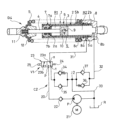
- FIG. 1 is a diagram showing a shock absorber with a vehicle height adjustment function according to the first embodiment.
- FIG. 2 is a diagram showing a shock absorber with a vehicle height adjustment function in a first modified example of the first embodiment.
- FIG. 3 is a diagram showing a shock absorber with a vehicle height adjustment function in a second modification of the first embodiment.
- FIG. 4 is a diagram showing a shock absorber with a vehicle height adjustment function according to the second embodiment.
- FIG. 5 is a diagram showing a shock absorber with a vehicle height adjustment function in a first modified example of the second embodiment.
- FIG. 6 is a diagram showing a shock absorber with a vehicle height adjustment function in a second modified example of the second embodiment.
- FIG. 1 is a diagram showing a shock absorber with a vehicle height adjustment function according to the first embodiment.
- FIG. 2 is a diagram showing a shock absorber with a vehicle height adjustment function in a first modified example of the first embodiment.
- FIG. 3 is a
- FIG. 7 is a diagram showing a shock absorber with a vehicle height adjustment function according to the third embodiment.
- FIG. 8 is a diagram showing the structure of a cap in a concrete example of the shock absorber with a vehicle height adjustment function according to the third embodiment.
- FIG. 9 is a vertical cross-sectional view of a specific example of the shock absorber with a vehicle height adjustment function according to the third embodiment.
- the shock absorber D1 with a vehicle height adjustment function in the first embodiment includes a shock absorber body 1, a suspension spring S that biases the shock absorber body 1 in the extension direction, and a liquid reservoir. It has a reservoir R, a damper circuit C1, a pump P, and a switching valve V1, and is used by being interposed between the vehicle body and the axle (not shown).
- the vehicle in which the shock absorber with vehicle height adjustment function of each embodiment is used is not limited to a motorcycle, and may be an automobile or other vehicle.
- the shock absorber body 1 in the present embodiment includes a cylinder 2 filled with liquid, a piston 3 that is movably inserted into the cylinder 2 and partitions the inside of the cylinder 2 into an expansion side chamber R1 and a compression side chamber R2, and a cylinder A cylindrical outer that forms an annular gap 6 that covers the outer periphery of the cylinder 2 and communicates with the expansion side chamber R1 between the piston rod 4 that is movably inserted into the cylinder 2 and connected to the piston 3.
- a shell 5 is provided.
- the cylinder 2 has a cylindrical shape, and as described above, the piston 3 is inserted therein so as to be axially movable with respect to the cylinder 2.
- Pressure-side chambers R2 are respectively partitioned on the right side in FIG.
- hydraulic fluid for example, is filled in the expansion side chamber R1 and the compression side chamber R2 as hydraulic fluid.
- working liquid other than working oil, for example, liquid such as water or aqueous solution may be used.
- a flange 2b is provided at the right end of the cylinder 2 in FIG.
- a piston rod 4 connected to the piston 3 is inserted into the cylinder 2 so as to be axially movable. Furthermore, the cylinder 2 is accommodated in a cylindrical outer shell 5 arranged on the outer peripheral side, and an annular gap 6 is formed between the cylinder 2 and the outer shell 5 .
- An annular rod guide 7 is attached to the left end of the cylinder 2 and the outer shell 5 in FIG.
- the rod guide 7 includes a seal ring 7a that slides on the outer periphery of the piston rod 4, and a cylindrical bushing 7b that slides on the outer periphery of the piston rod 4. 2 guides axial movement.
- a cap 8 that closes the bottom ends of the cylinder 2 and the outer shell 5 is attached to the bottom end of the cylinder 2 and the outer shell 5, which is the right end in FIG. Openings at both ends of the cylinder 2 and the outer shell 5 are closed by rod guides 7 and caps 8, and both ends of the annular gap 6 in the cylinder 2 and between the cylinder 2 and the outer shell 5 are closed. .
- the cap 8 has a cylindrical shape with a bottom, and the outer circumference of the flange 2b of the cylinder 2 is fitted to the inner circumference.
- a screw portion 5b provided on the outer periphery of the outer shell 5 is screwed into the inner periphery of the cap 8, and the flange 2b of the cylinder 2 is held between the outer shell 5 and the bottom of the cap 8, and the cylinder 2 is held by the cap 8.
- the structure for fastening the cylinder 2 and the outer shell 5 to the cap 8 described above is an example, and other fastening structures may be employed.
- the cap 8 is also provided with a port 8a that opens from the side and communicates with the annular gap 6, and a port 8b that similarly opens from the side and communicates with the compression side chamber R2. Ports 8a and 8b are each connected to a damper circuit C1.
- a hole 2 a is provided in the vicinity of the head end of the cylinder 2 to communicate the expansion side chamber R 1 with the annular gap 6 . Therefore, the expansion side chamber R1 is connected to the damper circuit C1 via the annular gap 6 and the port 8a, and the compression side chamber R2 is connected to the damper circuit C1 via the port 8b.
- the cap 8 is provided with a bottom-side spring bearing 8c which is an annular stepped portion provided on the outer periphery closer to the cylinder than the openings of the ports 8a and 8b.
- the piston 3 is provided with a relief passage 9 that communicates the expansion side chamber R1 and the compression side chamber R2, and a relief valve 10 that opens and closes the relief passage 9.
- the relief valve 10 opens when the pressure in the expansion-side chamber R1 exceeds the pressure in the compression-side chamber R2 and the differential pressure between the two reaches the valve opening pressure, allowing only the flow of hydraulic oil from the expansion-side chamber R1 to the compression-side chamber R2. do.
- a bracket 11 for mounting the piston rod 4 to the vehicle is attached to the left end of the piston rod 4 in FIG. there is Note that the head-side spring bearing 12 may be directly attached to the piston rod 4 .
- a suspension spring S is interposed between the head-side spring bearing 12 and the bottom-side spring bearing 8c formed on the cap 8.
- the suspension spring S is interposed in a compressed state between the head-side spring bearing 12 and the bottom-side spring bearing 8c, and always biases the piston rod 4 in the direction of protruding outward from the cylinder 2. As shown in FIG. That is, the suspension spring S biases the shock absorber main body 1 in the extension direction.
- the inside of the reservoir R is partitioned by a diaphragm into a liquid chamber filled with hydraulic oil and an air chamber filled with gas, although not shown.
- the hydraulic oil in the liquid chamber is an accumulator pressurized by the pressure of the gas in the air chamber.
- the reservoir R may be one that only stores hydraulic fluid and does not pressurize the fluid chamber.
- the partition between the liquid chamber and the air chamber in the reservoir R may be a free piston, a bellows, or the like instead of the diaphragm.
- the damper circuit C1 includes a first passage 13 having one end connected to the expansion side chamber R1, a second passage 14 connecting the other end of the first passage 13 to the reservoir R, and the first passage 13 and the second passage 14.
- a third passage 15 that connects the first connection point J1, which is a connection point, to the compression side chamber R2, and a third passage 15 that is provided in the first passage 13 and provides resistance to the flow of hydraulic oil from the expansion side chamber R1 toward the first connection point J1.
- a first extension side damping valve 16 and a first extension side check valve provided in the first passage 13 in parallel with the first extension side damping valve to allow only the flow of hydraulic oil from the first connection point J1 toward the extension side chamber R1.
- valve 17 a valve 17; a first compression damping valve 18 provided in the second passage 14 to provide resistance to the flow of hydraulic oil from the first connection point J1 to the reservoir R; A first pressure side check valve 19 is provided in parallel and allows only the flow of hydraulic fluid from the reservoir R toward the first connection point J1.
- the first passage 13 has one end connected to the expansion side chamber R1 and the other end connected to the second passage 14 .
- the second passage 14 is connected to the first passage 13 at one end and to the reservoir R at the other end.
- the first passage 13 and the second passage 14 are connected in series, and the growth side chamber R1 is connected to the reservoir R via the first passage 13 and the second passage 14.
- the third passage 15 has one end connected to the pressure side chamber R2 and the other end connected to the first connection point J1 between the first passage 13 and the second passage 14 . Therefore, the growth side chamber R1 is connected to the compression side chamber R2 through the first passage 13 and the third passage 15, and the compression side chamber R2 is connected to the reservoir R through the third passage 15 and the second passage 14.
- the first extension side damping valve 16 allows only the flow of hydraulic oil passing through the first passage 13 from the extension side chamber R1 toward the first connection point J1. It is a damping valve that gives resistance to the flow of hydraulic oil that passes through it, and is, for example, a leaf valve or a poppet valve.
- the first rebound damping valve 16 may be a valve such as an orifice or a choke that allows bidirectional flow.
- the first expansion side check valve 17 is provided in the first passage 13 in parallel with the first expansion side damping valve, and passes through the first passage 13 from the first connection point J1 toward the expansion side chamber R1. Permits only the flow of hydraulic fluid and blocks the reverse flow of hydraulic fluid.
- the first compression side damping valve 18 only allows hydraulic oil to flow through the second passage 14 from the first connection point J1 toward the reservoir R. It is a damping valve that provides resistance to the flow of hydraulic oil passing through it, and is, for example, a leaf valve or a poppet valve.
- the first compression damping valve 18 may be a valve that allows bidirectional flow, such as an orifice or choke.
- the first pressure side check valve 19 is provided in the second passage 14 in parallel with the first pressure side damping valve 18, and the hydraulic oil passing through the second passage 14 from the reservoir R toward the first connection point J1 is Only allow the flow of hydraulic oil in the opposite direction and prevent the flow in the opposite direction.
- the pump P is provided in a pump passage 20, one end of which is connected to the reservoir R and the other end of which communicates with the switching valve V1. It is a one-way pump that discharges toward V1.
- the pump P is a gear pump, it may be a piston pump, a screw pump, or any other type of pump.
- the pump passage 20 is provided with a pump passage check valve 22 that allows only the flow of hydraulic oil from the pump P toward the switching valve V1. Hydraulic oil is prevented from flowing backward.
- the switching valve V1 is a 3-port, 2-position electromagnetic switching valve having three ports a, t, and p. 16 and the first expansion-side check valve 17 on the expansion-side chamber side, and the port p is connected to the other end of the pump passage 20 .
- the switching valve V1 has a first position 23a that connects the port a and the port t to communicate the first passage 13 and closes the port p to block the other end of the pump passage 20;
- a valve body 23 having a second position 23b that closes the first passage 13 by closing the first passage 13 and connects the port a and the port p to communicate the pump passage 20 and the expansion side chamber R1, and the first position It has a spring 24 for biasing the valve body 23 to take the position 23a, and a solenoid 25 for switching the valve body 23 to the second position 23b against the biasing force of the spring 24 when energized.
- the switching valve V1 when the switching valve V1 takes the first position 23a without energizing the solenoid 25, the pump passage 20 is blocked and the shock absorber main body 1 is connected to the damper circuit C1 through the first passage 13, thereby C1 becomes effective, and the shock absorber D1 with a vehicle height adjustment function enters the damper mode.
- the solenoid 25 is energized and the switching valve V1 takes the second position 23b, the first passage 13 is blocked, the pump passage 20 is connected to the expansion side chamber R1, and the pump P becomes effective, thereby enabling the vehicle height adjustment function.
- the attached shock absorber D1 is in the vehicle height adjustment mode.
- the switching valve V1 can select and switch the damper D1 with the vehicle height adjustment function between the damper mode in which only the damper circuit C1 is activated and the vehicle height adjustment mode in which the pump P is activated.
- the shock absorber D1 with the vehicle height adjustment function of the first embodiment is configured as described above, and its operation will be explained below. First, the operation when the switching valve V1 selects the first position 23a and the damper D1 with the vehicle height adjustment function is set to the damper mode will be described.
- the switching valve V1 connects the expansion side chamber R1 to the damper circuit C1 via the first passage 13, and connects the pressure side chamber R2 and the reservoir R via the damper circuit C1, while the pump passage 20 is connected to The connection between the expansion side chamber R1 and the pump P is cut off.
- This deficient hydraulic oil passes through the first pressure-side check valve 19 in the second passage 14 from the reservoir R, and is supplied to the pressure-side chamber R2 via the third passage 15 .
- the first extension damping valve 16 gives resistance to the flow of hydraulic oil moving from the extension side chamber R1 to the compression side chamber R2, so the pressure in the extension side chamber R1 increases, the pressure in the compression side chamber R2 becomes substantially equal to the pressure in the reservoir R, so the shock absorber D1 with a vehicle height adjustment function generates a rebound damping force that prevents the shock absorber main body 1 from extending.
- the excess hydraulic oil is discharged to the reservoir R via the first compression damping valve 18 in the second passage 14 .
- the first compression damping valve 18 gives resistance to the flow of hydraulic fluid moving from the compression side chamber R2 to the reservoir R, so that the expansion chamber R1 and the compression chamber R2 The internal pressure rises and becomes approximately equal.
- the shock absorber D1 with a vehicle height adjustment function is a shock absorber A compression side damping force is generated to prevent contraction of the main body 1 .
- the shock absorber D1 with a vehicle height adjustment function adopts the damper mode
- the shock absorber main body 1 is expanded and contracted by an external force
- the shock absorber D1 with a vehicle height adjustment function exerts a damping force that prevents the shock absorber main body 1 from expanding and contracting. Occur.
- the operation when the switching valve V1 selects the second position 23b and the shock absorber D1 with the vehicle height adjustment function is set to the vehicle height adjustment mode will be described.
- the switching valve V1 takes the second position 23b the pump passage 20 is connected to the expansion side chamber R1, the first passage 13 is blocked, and the portion of the first passage 13 from the switching valve V1 to the first connection point J1 is closed. , the hydraulic oil does not flow.
- the pump P is driven so that the shock absorber D1 with a vehicle height adjustment function compresses the suspension spring S to contract the shock absorber main body 1.
- Vehicle height can be lowered.
- the elastic force of the suspension spring S increases by the amount of compression of the suspension spring S, and the shock absorber body 1 is urged in the extension direction, so the pressure in the extension side chamber R1 becomes high.
- the pump passage check valve 22 is provided in the pump passage 20, and the hydraulic oil in the expansion side chamber R1 cannot move, so the shock absorber main body 1 is maintained in a contracted state.
- the vehicle height is also maintained in a lowered state.
- the shock absorber D1 with a vehicle height adjustment function can adjust the contraction amount of the shock absorber main body 1 according to the amount of hydraulic oil supplied from the pump P. If a stroke sensor for detecting the expansion and contraction displacement of the shock absorber main body 1 is provided, the contraction amount of the shock absorber main body 1 can be grasped. By controlling, the contraction amount of the shock absorber main body 1 can be adjusted to a predetermined contraction amount. Further, for example, when the passenger of the vehicle can operate the motor 21, the passenger can adjust the vehicle height by driving the pump P until the vehicle height desired by the passenger is achieved.
- the shock absorber D1 with the vehicle height adjustment function When the shock absorber D1 with the vehicle height adjustment function is in the vehicle height adjustment mode and the shock absorber body 1 is contracted, an external force acts on the shock absorber body 1 to expand it, and the pressure in the extension side chamber R1 is set in advance.
- the relief valve 10 opens to allow the hydraulic fluid to move from the expansion side chamber R1 to the compression side chamber R2. Therefore, even if the shock absorber D1 with a height adjustment function is in the height adjustment mode and the passenger drives the vehicle and the shock absorber main body 1 extends, the pressure in the extension side chamber R1 is excessive. Therefore, the shock absorber D1 with a vehicle height adjustment function is protected.
- the switching valve V1 is switched from the second position 23b to the first position 23a to shift the height-adjustable buffer D1 to the damping mode.
- the expansion side chamber R1 is connected to the damper circuit C1 through the first passage 13, the pump passage 20 is blocked, and the connection between the pump P and the expansion side chamber R1 is cut off.
- the suspension spring S which has been compressed by lowering the vehicle height, extends the shock absorber main body 1, so that the hydraulic oil is pushed out from the rebound side chamber R1, and the first rebound damping valve 16 and the third passage 15 are pushed out.
- the shock absorber main body 1 Since the suspension spring S expands until the elastic force exerted by itself balances the load received from the vehicle body of the vehicle, the shock absorber main body 1 also returns from the state in which the vehicle height was lowered to the state before the vehicle height was lowered. . Therefore, when the vehicle height adjustment mode is switched to the damper mode, the damper D1 with the vehicle height adjustment function can return to the state before the vehicle height adjustment by using the elastic force of the suspension spring S.
- the first extension damping valve 16 gives resistance to the flow of hydraulic oil, so the shock absorber body 1 expands at a moderately slow speed. As a result, the passenger does not feel uncomfortable.
- the damper D1 with the vehicle height adjustment function when the damper D1 with the vehicle height adjustment function is in the vehicle height adjustment mode, the vehicle height is lowered by driving the pump P.
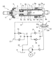
- the vehicle height adjustment mode when it is desired to raise the vehicle height in the vehicle height adjustment mode, may be configured like the shock absorber D2 with a vehicle height adjustment function of the first modification of the first embodiment shown in FIG.
- the shock absorber D2 with a vehicle height adjustment function of the first modification of the first embodiment differs from the shock absorber D1 with a vehicle height adjustment function of the first embodiment in the installation position of the switching valve V1.
- the switching valve V1 is provided in the middle of the first passage 13, and by switching the switching valve V1, the expansion side chamber R1 and the damper circuit C1 are connected and the expansion side chamber R1 and the pump passage 20 are connected.
- the connection has been selectively switched, if it is desired to raise the vehicle height in the vehicle height adjustment mode, the switching valve V1 is provided in the middle of the third passage 15 like the shock absorber D2 with the vehicle height adjustment function.
- the connection between the pressure-side chamber R2 and the damper circuit C1 and the connection between the pressure-side chamber R2 and the pump passage 20 may be selectively switched.
- the switching valve V1 when the switching valve V1 takes the first position 23a, it connects the port a and the port t to communicate the third passage 15, connects the compression side chamber R2 and the damper circuit C1, and closes the port p. to cut off the connection between the pump P and the pressure side chamber R2.
- the switching valve V1 When the switching valve V1 is in the second position 23b, it closes the port t to cut off the third passage 15 to cut off the connection between the pressure side chamber R2 and the damper circuit C1, and to connect the port a and the port p.
- the switching valve V1 takes the first position 23a without energizing the solenoid 25, the pump passage 20 is blocked and the shock absorber main body 1 is connected to the damper circuit C1 through the third passage 15, thereby C1 becomes effective, and the shock absorber D2 with a vehicle height adjustment function enters the damper mode.
- the solenoid 25 is energized and the switching valve V1 assumes the second position 23b, the third passage 15 is blocked, the pump passage 20 is connected to the compression side chamber R2, and the pump P becomes effective, thus enabling the vehicle height adjustment function.
- the attached shock absorber D2 is in the vehicle height adjustment mode.
- the switching valve V1 enables the damper mode that enables only the damper circuit C1 and the pump P even in the shock absorber D2 with the vehicle height adjustment function of the first modification of the first embodiment. You can select and switch between vehicle height adjustment mode.
- the relief valve 101 is provided in the relief passage 9 in the opposite direction to the shock absorber D1 with the vehicle height adjustment function.
- the shock absorber D2 with a vehicle height adjustment function of the first modified example of the first embodiment is configured as described above, and its operation will be explained below. First, the operation when the switching valve V1 selects the first position 23a and the damper D1 with the vehicle height adjustment function is set to the damper mode will be described.
- the switching valve V1 connects the pressure side chamber R2 to the damper circuit C1 via the third passage 15, and connects the expansion side chamber R1 and the reservoir R via the damper circuit C1, while the pump passage 20 is The connection between the pressure-side chamber R2 and the pump P is cut off.
- This deficient hydraulic oil passes through the first pressure-side check valve 19 in the second passage 14 from the reservoir R, and is supplied to the pressure-side chamber R2 via the third passage 15 .
- the first extension damping valve 16 gives resistance to the flow of hydraulic oil moving from the extension side chamber R1 to the compression side chamber R2, so the pressure in the extension side chamber R1 increases, the pressure in the compression side chamber R2 becomes substantially equal to the pressure in the reservoir R, so the shock absorber D2 with a vehicle height adjustment function generates a rebound damping force that prevents the shock absorber main body 1 from extending.
- the excess hydraulic oil is discharged to the reservoir R via the first compression damping valve 18 in the second passage 14 .
- the first compression damping valve 18 gives resistance to the flow of hydraulic fluid moving from the compression side chamber R2 to the reservoir R, so that the expansion chamber R1 and the compression chamber R2 The internal pressure rises and becomes approximately equal.
- the shock absorber D2 with a vehicle height adjustment function is a shock absorber.
- a compression side damping force is generated to prevent contraction of the main body 1 .
- the shock absorber D2 with a vehicle height adjustment function of the first modified example of the first embodiment adopts the damper mode
- the shock absorber can When the main body 1 is expanded and contracted by an external force, the shock absorber D1 with a vehicle height adjustment function generates a damping force that prevents the expansion and contraction of the shock absorber main body 1. - ⁇
- the operation when the switching valve V1 selects the second position 23b and the shock absorber D2 with the vehicle height adjustment function is set to the vehicle height adjustment mode will be described.
- the switching valve V1 takes the second position 23b the pump passage 20 is connected to the pressure side chamber R2, the third passage 15 is blocked, and the portion of the third passage 15 from the switching valve V1 to the first connection point J1 is closed. , the hydraulic oil does not flow.
- the pump P is driven so that the shock absorber D2 with a vehicle height adjustment function extends the shock absorber main body 1 to lift the vehicle body. can raise the height.
- the suspension spring S also expands and the elastic force of the suspension spring S decreases. is high pressure.
- the pump passage check valve 22 is provided in the pump passage 20, and the hydraulic oil in the extension side chamber R1 cannot move, so the shock absorber main body 1 is maintained in an extended state. and the vehicle height is maintained in a raised state.
- the shock absorber D2 with a vehicle height adjustment function can adjust the extension amount of the shock absorber main body 1 according to the amount of hydraulic oil supplied from the pump P. If a stroke sensor for detecting the expansion and contraction displacement of the shock absorber main body 1 is provided, the extension amount of the shock absorber main body 1 can be grasped. By controlling, the extension amount of the shock absorber main body 1 can be adjusted to a predetermined extension amount. Further, for example, when the passenger of the vehicle can operate the motor 21, the passenger can adjust the vehicle height by driving the pump P until the vehicle height desired by the passenger is achieved.
- the valve opens to prevent the flow of hydraulic oil from the compression side chamber R2 to the expansion side chamber R1.
- a relief valve 101 is provided to allow. In this way, even if the shock absorber body 1 shrinks due to the passenger driving the vehicle while the shock absorber D2 with the height adjustment function is in the height adjustment mode, contraction is allowed, and the vibration of the vehicle body can be reduced.
- the switching valve V1 is switched from the second position 23b to the first position 23a to shift the vehicle height adjustment function buffer D2 to the damping mode.
- the pressure side chamber R2 is connected to the damper circuit C1 through the third passage 15, the pump passage 20 is blocked, and the connection between the pump P and the pressure side chamber R2 is cut off.
- the suspension spring S and the shock absorber main body 1 which have been elongated by raising the vehicle height, are contracted by the load received from the vehicle body, so that the hydraulic oil is pushed out from the compression side chamber R2 and the first expansion side check valve is opened.
- the shock absorber main body 1 Since the suspension spring S contracts until the elastic force exerted by itself balances the load received from the vehicle body of the vehicle, the shock absorber main body 1 also returns from the state in which the vehicle height is raised to the state before the vehicle height is raised. . Therefore, when the vehicle height adjustment mode is switched to the damper mode, the damper D2 with the vehicle height adjustment function can return to the state before the vehicle height adjustment by utilizing the load received from the vehicle body. In addition, when the shock absorber body 1 returns to its original state from the expanded state, the first compression damping valve 18 gives resistance to the flow of hydraulic oil, so the contraction speed of the shock absorber body 1 moderately slows down. , without causing discomfort to passengers.
- the damper D1 with a vehicle height adjustment function when the damper D1 with a vehicle height adjustment function is in the vehicle height adjustment mode, the vehicle height is lowered by driving the pump P, and when the damper D2 with a vehicle height adjustment function is in the vehicle height adjustment mode.
- the vehicle height is raised by driving the pump P, if it is desired to raise or lower the vehicle height in the vehicle height adjustment mode, the second modification of the first embodiment shown in FIG. It may be constructed like the shock absorber D3 with a vehicle height adjustment function.
- the shock absorber D3 with a vehicle height adjustment function of the second modification of the first embodiment differs from the shock absorber D1 with a vehicle height adjustment function of the first embodiment in that the configuration and installation position of the switching valve V2 are different. different.
- the switching valve V2 is provided in the middle of the first passage 13 and the third passage 15, and by switching the switching valve V2, the expansion side chamber R1 and the compression side chamber R2 are connected to the damper circuit C1. , the connection between the expansion side chamber R1 and the pump passage 20 and the connection between the compression side chamber R2 and the pump passage 20 are selectively switched.
- the damper D3 with a vehicle height adjustment function has two vehicle height adjustment modes, a mode for raising the vehicle height and a mode for lowering the vehicle height, and the vehicle height is raised by switching the switching valve V2. It is possible to switch between a mode and a mode that lowers the vehicle height, and it is also possible to select a damper mode.
- the switching valve V2 is a 5-port 3-position electromagnetic switching valve provided with 5 ports a1, b1, t1, t2, p1. It comprises a valve body 26 having a position 26b and a right position 26c, springs 27a and 27b that urge the valve body 26 to assume the neutral position 26b, and a push-pull solenoid 28.
- the switching valve V2 connects the ports a1 and t1 in the middle of the first passage 13, and in the middle of the first passage 13, the first expansion side damping valve 16 and the first expansion side check valve 17 are connected to the expansion side chamber.
- Ports b 1 and t 2 are connected in the middle of the third passage 15
- port p 1 is connected to the other end of the pump passage 20 .
- valve body 26 assumes a neutral position 26b by means of springs 27a and 27b, connects the port a1 and the port t1 to communicate the first passage 13, and connects the port b1 and the port t2.
- the third passage 15 is made to communicate, and the port p1 is closed to block the other end of the pump passage 20 .
- valve body 26 when the valve body 26 is pushed leftward by the energization of the solenoid 28, the valve body 26 assumes the left position 26a, closes the port t1 to shut off the first passage 13, connects the port a1 and the port p1, and opens the pump passage. 20 and the expansion side chamber R1 are communicated, and the port b1 and the port t2 are connected to communicate the third passage 15.
- valve body 26 when the valve body 26 is pushed rightward by the energization of the solenoid 28, the valve body 26 assumes the right position 26c, closes the port t2 to shut off the third passage 15, connects the port b1 and the port p1, and opens the pump passage. 20 and the pressure side chamber R2 are communicated, and the first passage 13 is communicated by connecting the port a1 and the port t1.
- the switching valve V2 takes the neutral position 26b without energizing the solenoid 28, the pump passage 20 is blocked and the shock absorber body 1 is connected to the damper circuit C1 through the first passage 13 and the third passage 15. As a result, the damper circuit C1 becomes effective, and the shock absorber D3 with a vehicle height adjustment function enters the damper mode.
- the solenoid 28 is energized to switch the switching valve V2 to the left position 26a, the first passage 13 is blocked, the pump passage 20 is connected to the expansion side chamber R1, the pump P becomes active, and the compression side chamber R2 is the first.
- the damper D3 with a vehicle height adjustment function Connected to the damper circuit C1 via the 3 passages 15, the damper D3 with a vehicle height adjustment function enters a vehicle height adjustment mode for lowering the vehicle height. Further, when the solenoid 28 is energized to switch the switching valve V2 to the right position 26c, the third passage 15 is blocked, the pump passage 20 is connected to the pressure side chamber R2, the pump P becomes effective, and the expansion side chamber R1 is the first. Connected to the damper circuit C1 via the 1 passage 13, the damper D3 with a vehicle height adjustment function enters a vehicle height adjustment mode for increasing the vehicle height.
- the switching valve V2 has a damper mode in which only the damper circuit C1 of the damper D3 with a vehicle height adjustment function is activated, a vehicle height adjustment mode in which the vehicle height is lowered while the pump P is activated, and a pump P is activated. You can select and switch to one of the vehicle height adjustment modes that increase the vehicle height while
- the shock absorber main body 1 includes a relief passage 9 connecting the expansion side chamber R1 and the compression side chamber R2, and a relief passage 9 provided in the relief passage 9 for the expansion side chamber R1.
- the valve opens and the hydraulic oil (liquid) flows from the expansion side chamber R1 to the compression side chamber R2.
- the shock absorber main body 1 may extend when the passenger drives the vehicle with the vehicle height lowered in the vehicle height adjustment mode. Also, even if the passenger drives the vehicle with the vehicle height raised in the vehicle height adjustment mode and the shock absorber main body 1 contracts, the compression side chamber The pressure in R2 does not become excessive, and the shock absorber D3 with a vehicle height adjustment function is protected.
- the shock absorber D3 with a vehicle height adjustment function of the second modification of the first embodiment is configured as described above, and its operation will be explained below.
- the operation when the switching valve V2 selects the neutral position 26b and the damper D3 with the vehicle height adjustment function is set to the damper mode will be described.
- the connection state between the shock absorber main body 1 and the damper circuit C1 in the shock absorber D3 with the vehicle height adjustment function is the same as that of the shock absorber D1 with the vehicle height adjustment function of the first embodiment in the damper mode. This is the same as the connection state between the device main body 1 and the damper circuit C1.
- the shock absorber D3 with the vehicle height adjustment function of the second modification of the first embodiment is similar to the shock absorber D1 with the vehicle height adjustment function of the first embodiment in the damper mode.
- a damping force that prevents the shock absorber main body 1 from expanding and contracting is generated.
- the connection state between the shock absorber main body 1, the pump P and the damper circuit C1 in the shock absorber D3 with the vehicle height adjustment function is the same as that of the first embodiment with the vehicle height adjustment function in the vehicle height adjustment mode. This is the same as the connection state between the shock absorber main body 1, the pump P and the damper circuit C1 in the shock absorber D1.
- the shock absorber main body 1 can be contracted by driving the pump P to lower the vehicle height.
- switching the switching valve V2 to the neutral position 26b and setting the damper D3 with the vehicle height adjustment function to the damper mode connects the expansion side chamber R1 to the compression side chamber R2 and the reservoir R through the damper circuit C1. Since the shock absorber main body 1 is allowed to extend, the shock absorber main body 1 returns to the original displaced state before the vehicle height is lowered by the resilient force of the suspension spring S.
- the connection state between the shock absorber main body 1, the pump P and the damper circuit C1 in the shock absorber D3 with a vehicle height adjustment function is the same as that of the first modification of the first embodiment in the vehicle height adjustment mode. This is the same as the connection state between the shock absorber main body 1, the pump P and the damper circuit C1 in the shock absorber D2 with a vehicle height adjustment function.
- the vehicle height adjustment mode is the same as that of the first embodiment in the vehicle height adjustment mode.
- the shock absorber body 1 can be extended by driving the pump P to raise the vehicle height in the same manner as the shock absorber D2 with a vehicle height adjustment function of the modified example. After raising the vehicle height, if the switching valve V2 is switched to the neutral position 26b and the damper D3 with the vehicle height adjustment function is set to the damper mode, the hydraulic oil in the compression side chamber R2 flows through the damper circuit C1 into the expansion side chamber R1 and the reservoir. Since the shock absorber main body 1 can be moved to R and contraction of the shock absorber main body 1 is allowed, the shock absorber main body 1 contracts, receives the load of the vehicle body, and returns to the original displaced state before the vehicle height is raised.
- the shock absorbers D1, D2, and D3 with a vehicle height adjustment function include the cylinder 2 filled with hydraulic oil (liquid), and the cylinder 2 movably inserted into the cylinder 2.
- a shock absorber main body 1 having a piston 3 that divides the into an expansion-side chamber R1 and a compression-side chamber R2; a piston rod 4 that is movably inserted into the cylinder 2 and connected to the piston 3;
- Suspension spring S biasing in the direction, reservoir R storing hydraulic oil (liquid), expansion side chamber R1, compression side chamber R2, and reservoir R connected to damping force on shock absorber body 1 when shock absorber body 1 expands and contracts a damper circuit C1 for generating a damper circuit C1, a pump P capable of sucking and discharging liquid from a reservoir R, and a damper body 1 installed between the damper body 1 and the damper circuit C1 and the pump P to connect the damper body 1 to the damper circuit C1 A damper mode for generating a damping force
- the damper circuit C1 and the pump P can be selectively activated by the switching valves V1, V2, so that the shock absorber main body 1 can reduce the damping force.
- the pump P is driven to supply hydraulic oil (liquid) into the shock absorber main body 1 to extend or extend the shock absorber main body 1. Since it can be contracted or expanded, a jack for driving the spring bearing of the suspension spring S becomes unnecessary.
- the jack and the tank for the jack which were required in the conventional shock absorber with the vehicle height adjustment function, are not required. , it can be made smaller even if it has a vehicle height adjustment function.
- the switching valves V1 and V2 move the pump P into the expansion side chamber R1 and the compression side chamber of the shock absorber main body 1.
- R2 and the other of the expansion side chamber R1 and the compression side chamber R2 is connected to the reservoir R via the damper circuit C1.
- the damper circuit C1 is used to reserve the compressed chamber of the expansion side chamber R1 and the compression side chamber R2 when adjusting the vehicle height. Since it is connected to R, there is no need to provide a passage that communicates the compression side chamber with the reservoir R only for adjusting the vehicle height, so that the size can be further reduced.
- the damper circuit C1 includes the first passage 13, one end of which is connected to the expansion side chamber R1, and the other end of the first passage 13, which serves as a reservoir.
- a third passage 15 connecting a first connection point J1, which is a connection point between the first passage 13 and the second passage 14, to the pressure-side chamber R2; a first expansion side damping valve 16 that provides resistance to the flow of hydraulic oil (liquid) from the expansion side chamber R1 toward the first connection point J1; A first expansion side check valve 17 that allows only the flow of hydraulic oil (liquid) from the first connection point J1 toward the expansion side chamber R1, and a first expansion side check valve 17 provided in the second passage 14 and directed from the first connection point J1 to the reservoir R A first pressure-side damping valve 18 that provides resistance to the flow of hydraulic oil (liquid); ), and a first pressure side check valve 19 that allows only the flow of .
- the vehicle height adjustment mode is switched to the damper mode, and the shock absorber main body 1 expands or contracts to adjust the vehicle height before the vehicle height adjustment.
- the first expansion-side damping valve 16 or the first compression-side damping valve 18 gives resistance to the flow of hydraulic oil (liquid), so that the expansion and contraction of the shock absorber main body 1 becomes gradual, without making people feel uncomfortable.
- the switching valve V1 has a first position 23a that connects the first passage 13 in the damper mode and disconnects the pump P and the shock absorber body 1, and a vehicle height adjustment mode that cuts off the first passage 13 to open the pump.
- P and the second position 23b connecting the shock absorber main body 1, the shock absorber D1 with a vehicle height adjustment function can contract the shock absorber main body 1 in the vehicle height adjustment mode to lower the vehicle height.
- the switching valve V1 has a first position 23a in which the third passage 15 is communicated in the damper mode to disconnect the pump P from the shock absorber main body 1, and a vehicle height adjustment mode in which the third passage 15 is cut off to open the pump.
- the shock absorber D2 with height adjustment function can raise the shock absorber main body 1 in the height adjusting mode to raise the vehicle height.
- the switching valve V2 has a neutral position 26b in which the first passage 13 and the third passage 15 are communicated in the damper mode to disconnect the pump P and the shock absorber main body 1, and the first passage in the vehicle height adjustment mode. 13 to connect the pump P to the shock absorber main body 1, and a right position 26c to cut off the third passage 15 and connect the pump P to the shock absorber main body 1.
- the shock absorber D3 with a vehicle height adjustment function can raise and lower the shock absorber main body 1 in the vehicle height adjustment mode, and raise and lower the vehicle height.
- the shock absorber body 1 includes a relief passage 9 connecting the expansion side chamber R1 and the compression side chamber R2, and the relief passage 9 provided in the expansion side chamber. It has relief valves 10 and 102 that open when the differential pressure between R1 and pressure side chamber R2 reaches the valve opening pressure to allow hydraulic oil (liquid) to flow from expansion side chamber R1 to pressure side chamber R2. According to the shock absorbers D1 and D3 with a vehicle height adjustment function configured in this manner, the shock absorber main body 1 may extend when the passenger drives the vehicle while the vehicle height is lowered in the vehicle height adjustment mode.
- the shock absorber main body 1 includes a relief passage 9 connecting the expansion side chamber R1 and the compression side chamber R2, and a compression side chamber provided in the relief passage 9. It has relief valves 101 and 102 that open when the differential pressure between R2 and the growth side chamber R1 reaches the valve opening pressure to allow hydraulic oil (liquid) to flow from the pressure side chamber R2 toward the growth side chamber R1.
- the shock absorber main body 1 is contracted when the passenger drives the vehicle with the vehicle height raised in the vehicle height adjustment mode. Even if this occurs, the pressure in the compression side chamber R2 does not become excessive, and the shock absorbers D2 and D3 with a vehicle height adjustment function are protected.
- the shock absorber D4 with a vehicle height adjustment function in the second embodiment includes a shock absorber main body 1, a suspension spring S that biases the shock absorber main body 1 in the extension direction, and a liquid reservoir. It has a reservoir R, a damper circuit C2, a pump P, and a switching valve V1.
- the shock absorber D4 with a vehicle height adjustment function of the second embodiment differs from the shock absorber D1 with a vehicle height adjustment function of the first embodiment in the configuration of the damper circuit C2.
- the damper circuit C2 includes a fourth passage 31 having one end connected to the expansion side chamber R1, a fifth passage 32 connecting the compression side chamber R2 to the other end of the fourth passage 31, and the fourth passage 31 and the fifth passage 32.
- a sixth passage 33 that connects the second connection point J2, which is a connection point of the second connection point J2, to the reservoir R, and a sixth passage 33 that is provided in the fourth passage 31 and provides resistance to the flow of hydraulic oil from the growth side chamber R1 toward the second connection point J2.
- a second expansion side damping valve 34 and a second expansion side reverse valve provided in the fourth passage 31 in parallel with the second expansion side damping valve 34 to allow only the flow of hydraulic oil from the second connection point J2 toward the expansion side chamber R1.
- the fourth passage 31 has one end connected to the expansion side chamber R1 and the other end connected to the fifth passage 32 .
- the fifth passage 32 has one end connected to the pressure-side chamber R ⁇ b>2 and the other end connected to the fourth passage 31 .
- the fourth passage 31 and the fifth passage 32 are connected in series, and the growth side chamber R1 is connected to the pressure side chamber R2 via the fourth passage 31 and the fifth passage 32.
- the sixth passage 33 has one end connected to the second connection point J2 between the fourth passage 31 and the fifth passage 32, and the other end connected to the reservoir R.
- the growth side house R1 and the compression side house R2 are connected to each other through the fourth passage 31 and the fifth passage 32.
- the growth side chamber R1 is connected to the reservoir R through the fourth passage 31 and the sixth passage 33
- the compression side chamber R2 is connected to the reservoir R through the fifth passage 32 and the sixth passage 33.
- the second extension side damping valve 34 allows only the flow of hydraulic oil passing through the fourth passage 31 from the extension side chamber R1 toward the second connection point J2. It is a damping valve that gives resistance to the flow of hydraulic oil that passes through it, and is, for example, a leaf valve or a poppet valve.
- the second expansion side damping valve 34 may be a valve such as an orifice or a choke that allows bidirectional flow.
- the second expansion side check valve 35 is provided in the fourth passage 31 in parallel with the second expansion side damping valve 34, and passes through the fourth passage 31 from the second connection point J2 toward the expansion side chamber R1.
- the second compression-side damping valve 36 allows only the flow of hydraulic oil passing through the fifth passage 32 from the compression-side chamber R2 toward the second connection point J2 in the damper D4 with a vehicle height adjustment function of the present embodiment. It is a damping valve that gives resistance to the flow of hydraulic oil that passes through it, and is, for example, a leaf valve or a poppet valve.
- the second compression damping valve 36 may be a valve such as an orifice or a choke that allows bidirectional flow.
- the second pressure-side check valve 37 is provided in the fifth passage 32 in parallel with the second pressure-side damping valve 36, and the second pressure-side check valve 37 passes through the fifth passage 32 from the second connection point J2 toward the pressure-side chamber R2.
- the switching valve V1 is a 3-port, 2-position electromagnetic switching valve provided with three ports a, t, and p, like the switching valve V1 in the shock absorber D1 with a vehicle height adjustment function of the first embodiment. Ports a and t are connected in the middle of the fourth passage 31 and provided on the expansion side chamber side of the second expansion side damping valve 34 and the second expansion side check valve 35, and the port p is connected to the other end of the pump passage 20. I am connecting.
- the switching valve V1 has a first position 23a that connects the port a and the port t to communicate the fourth passage 31 and closes the port p to block the other end of the pump passage 20;
- a valve body 23 having a second position 23b that closes the fourth passage 31 by closing the passage t and connects the port a and the port p to communicate the pump passage 20 and the expansion side chamber R1, and the first position It has a spring 24 for biasing the valve body 23 to take the position 23a, and a solenoid 25 for switching the valve body 23 to the second position 23b against the biasing force of the spring 24 when energized.
- the switching valve V1 when the switching valve V1 takes the first position 23a without energizing the solenoid 25, the pump passage 20 is blocked and the shock absorber main body 1 is connected to the damper circuit C2 via the fourth passage 31, thereby connecting the damper circuit to the damper circuit. C2 becomes effective, and the shock absorber D4 with a vehicle height adjustment function enters the damper mode.
- the solenoid 25 is energized and the switching valve V1 takes the second position 23b
- the fourth passage 31 is blocked, the pump passage 20 is connected to the extension side chamber R1, and the pump P becomes effective, thereby enabling the vehicle height adjustment function.
- the attached shock absorber D4 is in the vehicle height adjustment mode.
- the switching valve V1 can select and switch the damper D1 with the vehicle height adjustment function between the damper mode in which only the damper circuit C2 is activated and the vehicle height adjustment mode in which the pump P is activated.
- the shock absorber D4 with a vehicle height adjustment function of the second embodiment is configured as described above, and its operation will be explained below. First, the operation when the switching valve V1 selects the first position 23a and the damper D4 with the vehicle height adjustment function is set to the damper mode will be described.
- the switching valve V1 connects the expansion side chamber R1, the compression side chamber R2, and the reservoir R to each other through the damper circuit C2, while the pump passage 20 is blocked to disconnect the expansion side chamber R1 and the pump P. Cut off.
- This deficient hydraulic oil is supplied from the reservoir R through the second pressure-side check valves 37 of the sixth passage 33 and the fifth passage 32 to the pressure-side chamber R2.
- the second extension damping valve 34 gives resistance to the flow of hydraulic oil moving from the extension side chamber R1 to the compression side chamber R2, so the pressure in the extension side chamber R1 increases, the pressure in the compression side chamber R2 becomes substantially equal to the pressure in the reservoir R, so the shock absorber D4 with a vehicle height adjustment function generates a rebound damping force that prevents the shock absorber main body 1 from extending.
- the shock absorber D4 with a vehicle height adjustment function adopts the damper mode
- the shock absorber D4 with a vehicle height adjustment function exerts a damping force that prevents the shock absorber body 1 from expanding and contracting. Occur.
- the operation when the switching valve V1 selects the second position 23b and the shock absorber D4 with the vehicle height adjustment function is set to the vehicle height adjustment mode will be described.
- the switching valve V1 takes the second position 23b the pump passage 20 is connected to the expansion side chamber R1, the fourth passage 31 is blocked, and the portion of the fourth passage 31 from the switching valve V1 to the second connection point J2 is closed. , the hydraulic oil does not flow.
- the pump P is driven so that the shock absorber D4 with a vehicle height adjustment function compresses the suspension spring S to contract the shock absorber main body 1.
- Vehicle height can be lowered.
- the elastic force of the suspension spring S increases by the amount of compression of the suspension spring S, and the shock absorber body 1 is urged in the extension direction, so the pressure in the extension side chamber R1 becomes high.
- the pump passage check valve 22 is provided in the pump passage 20, and the hydraulic oil in the expansion side chamber R1 cannot move, so the shock absorber main body 1 is maintained in a contracted state.
- the vehicle height is also maintained in a lowered state.
- the shock absorber D4 with a vehicle height adjustment function can adjust the contraction amount of the shock absorber main body 1 according to the amount of hydraulic oil supplied from the pump P. If a stroke sensor for detecting the expansion and contraction displacement of the shock absorber body 1 is provided, the amount of extension of the shock absorber body 1 can be grasped. can be adjusted to a predetermined amount of shrinkage. Further, for example, when the passenger of the vehicle can operate the motor 21, the passenger can adjust the vehicle height by driving the pump P until the vehicle height desired by the passenger is achieved.
- the shock absorber D4 with the vehicle height adjustment function When the shock absorber D4 with the vehicle height adjustment function is in the vehicle height adjustment mode and the shock absorber body 1 is contracted, an external force acts on the shock absorber body 1 to expand it, and the pressure in the extension side chamber R1 is set in advance.
- the relief valve 10 opens to allow the hydraulic fluid to move from the expansion side chamber R1 to the compression side chamber R2. Therefore, even if the shock absorber D4 with a height adjustment function adopts the height adjustment mode and the passenger drives the vehicle and the shock absorber main body 1 extends, the pressure in the extension side chamber R1 is excessive. Therefore, the shock absorber D4 with a vehicle height adjustment function is protected.
- the switching valve V1 is switched from the second position 23b to the first position 23a, and the vehicle height adjustment function buffer D4 is turned into a damper.
- the expansion side chamber R1 is connected to the damper circuit C2 through the fourth passage 31, the pump passage 20 is blocked, and the connection between the pump P and the expansion side chamber R1 is cut off.
- the suspension spring S which has been compressed by lowering the vehicle height, expands the shock absorber main body 1, so that the hydraulic oil is pushed out from the rebound side chamber R1 and the second rebound side damping valve 34 and the fifth passage 32.
- the shock absorber main body 1 Since the suspension spring S expands until the elastic force exerted by itself balances the load received from the vehicle body of the vehicle, the shock absorber main body 1 also returns from the state in which the vehicle height was lowered to the state before the vehicle height was lowered. . Therefore, when the vehicle height adjustment mode is switched to the damper mode, the damper D4 with the vehicle height adjustment function can return to the state before the vehicle height adjustment by utilizing the elastic force of the suspension spring S.
- the second extension damping valve 34 gives resistance to the flow of hydraulic oil, so the shock absorber body 1 expands at a moderately slow speed. As a result, the passenger does not feel uncomfortable.
- the shock absorber D4 with a vehicle height adjustment function when the shock absorber D4 with a vehicle height adjustment function is in the vehicle height adjustment mode, the vehicle height is lowered by driving the pump P.
- the shock absorber D5 with the vehicle height adjustment function of the first modification of the second embodiment differs from the shock absorber D4 with the vehicle height adjustment function of the second embodiment in the installation position of the switching valve V1.
- the switching valve V1 is provided in the middle of the fourth passage 31, and by switching the switching valve V1, the connection between the expansion side chamber R1 and the damper circuit C2 and the connection between the expansion side chamber R1 and the pump passage 20 are achieved.
- the connection has been selectively switched, if it is desired to raise the vehicle height in the vehicle height adjustment mode, the switching valve V1 is provided in the middle of the fifth passage 32 as in the damper D5 with the vehicle height adjustment function. By switching V1, the connection between the pressure-side chamber R2 and the damper circuit C2 and the connection between the pressure-side chamber R2 and the pump passage 20 may be selectively switched.
- the ports a and t of the switching valve V1 are connected in the middle of the fifth passage 32 and the port p of the switching valve V1 is connected to the other end of the pump passage 20, good. That is, when the switching valve V1 takes the first position 23a, it connects the port a and the port t to communicate the fifth passage 32, connects the compression side chamber R2 and the damper circuit C2, and closes the port p. to cut off the connection between the pump P and the pressure side chamber R2. Further, when the switching valve V1 takes the second position 23b, the port t is closed to cut off the fifth passage 32 to cut off the connection between the pressure side chamber R2 and the damper circuit C2, and the port a and the port p.
- the switching valve V1 takes the first position 23a without energizing the solenoid 25, the pump passage 20 is blocked and the shock absorber main body 1 is connected to the damper circuit C2 via the fifth passage 32, thereby C2 becomes effective, and the shock absorber D5 with a vehicle height adjustment function enters the damper mode.
- the solenoid 25 is energized and the switching valve V1 assumes the second position 23b, the fifth passage 32 is blocked, the pump passage 20 is connected to the compression side chamber R2, and the pump P becomes active, thereby enabling the vehicle height adjustment function.
- the attached shock absorber D5 is in the vehicle height adjustment mode.
- the switching valve V1 enables the damper mode that enables only the damper circuit C2 and the pump P even in the shock absorber D5 with the vehicle height adjustment function of the first modification of the second embodiment. You can select and switch between vehicle height adjustment mode.
- a relief valve 101 is provided in the relief passage 9 in the opposite direction to the shock absorber D1 with a vehicle height adjustment function.
- the shock absorber D5 with a vehicle height adjustment function of the first modified example of the second embodiment is configured as described above, and its operation will be explained below. First, the operation when the switching valve V1 selects the first position 23a and the damper D5 with the vehicle height adjustment function is set to the damper mode will be described.
- the switching valve V1 connects the pressure-side chamber R2 to the damper circuit C2 via the fifth passage 32, and the expansion-side chamber R1, the pressure-side chamber R2, and the reservoir R are connected to each other via the damper circuit C2.
- the pump passage 20 is blocked and the connection between the pressure side chamber R2 and the pump P is cut off.
- the piston 3 moves leftward in FIG. 1 within the cylinder 2 to compress the extension side chamber R1 and expand the compression side chamber R2.
- the hydraulic fluid pushed out from the expansion side chamber R1 with the movement of the piston 3 passes through the second expansion side damping valve 34 of the fourth passage 31 and expands via the second pressure side check valve 37 of the fifth passage 32. to the pressure side chamber R2.
- the piston rod 4 moves out of the cylinder 2. Therefore, the amount of hydraulic oil that moves from the extension side chamber R1 to the compression side chamber R2 cannot cover the expanded volume of the compression side chamber R2. is withdrawn from the cylinder 2, the hydraulic oil becomes insufficient in the compression side chamber R2.
- This deficient hydraulic oil is supplied from the reservoir R through the second pressure-side check valves 37 of the sixth passage 33 and the fifth passage 32 to the pressure-side chamber R2.
- the second extension damping valve 34 gives resistance to the flow of hydraulic oil moving from the extension side chamber R1 to the compression side chamber R2, so the pressure in the extension side chamber R1 increases, the pressure in the compression side chamber R2 becomes substantially equal to the pressure in the reservoir R, so the shock absorber D2 with a vehicle height adjustment function generates a rebound damping force that prevents the shock absorber main body 1 from extending.
- This excess hydraulic oil is discharged from the compression-side chamber R2 to the reservoir R through the sixth passage 33 after passing through the second compression-side damping valve 36 in the fifth passage 32 .
- the shock absorber main body 1 performs the contraction operation, as described above, the hydraulic fluid pushed out from the compression side chamber R2 inevitably passes through the second compression damping valve 36, and resistance is applied to the flow of this hydraulic fluid. Therefore, the pressure in the compression side chamber R2 rises, the pressure in the expansion side chamber R1 becomes substantially equal to the pressure in the reservoir R, and the shock absorber D5 with a vehicle height adjustment function prevents contraction of the shock absorber main body 1. generate force.
- the shock absorber D5 with a vehicle height adjustment function adopts the damper mode
- the shock absorber main body 1 is expanded and contracted by an external force
- the shock absorber D5 with a vehicle height adjustment function exerts a damping force that prevents the shock absorber main body 1 from expanding and contracting. Occur.
- the operation when the switching valve V1 selects the second position 23b and the shock absorber D5 with the vehicle height adjustment function is set to the vehicle height adjustment mode will be described.
- the switching valve V1 takes the second position 23b the pump passage 20 is connected to the pressure side chamber R2, the fifth passage 32 is blocked, and the portion of the fifth passage 32 from the switching valve V1 to the second connection point J2 is closed. , the hydraulic oil does not flow.
- the pump P is driven so that the shock absorber D5 with a vehicle height adjustment function extends the shock absorber main body 1 to lift the vehicle body. can raise the height.
- the suspension spring S also expands and the elastic force of the suspension spring S decreases. is high pressure.
- the pump passage check valve 22 is provided in the pump passage 20, and the hydraulic oil in the extension side chamber R1 cannot move, so the shock absorber main body 1 is maintained in an extended state. and the vehicle height is maintained in a raised state.
- the shock absorber D5 with a vehicle height adjustment function can adjust the extension amount of the shock absorber main body 1 according to the amount of hydraulic oil supplied from the pump P. If a stroke sensor for detecting the expansion and contraction displacement of the shock absorber main body 1 is provided, the extension amount of the shock absorber main body 1 can be grasped. By controlling, the extension amount of the shock absorber main body 1 can be adjusted to a predetermined extension amount. Further, for example, when the passenger of the vehicle can operate the motor 21, the passenger can adjust the vehicle height by driving the pump P until the vehicle height desired by the passenger is achieved.
- the valve opens to prevent the flow of hydraulic oil from the compression side chamber R2 to the expansion side chamber R1.
- a relief valve 101 is provided to allow. In this way, even if a passenger causes the vehicle to run while the shock absorber D5 with the vehicle height adjustment function is in the vehicle height adjustment mode, the shock absorber body 1 is contracted. contraction is allowed, and the vibration of the vehicle body can be reduced.
- the switching valve V1 is switched from the second position 23b to the first position 23a, and the vehicle height adjustment function buffer D2 is turned into a damper.
- the pressure side chamber R2 is connected to the damper circuit C2 through the fifth passage 32, the pump passage 20 is blocked, and the connection between the pump P and the pressure side chamber R2 is cut off. Then, the suspension spring S and the shock absorber main body 1, which had been stretched by raising the vehicle height, contract due to the load received from the vehicle body.
- the shock absorber main body 1 While moving to the expansion side chamber R1 through the second expansion side check valve 35, the amount of hydraulic oil corresponding to the volume of the piston rod 4 entering the cylinder 2 flows from the compression side chamber R2 into the fifth passage 32 into the second It moves to the reservoir R via the compression side damping valve 36 and the sixth passage 33 . Since the suspension spring S contracts until the elastic force exerted by itself balances the load received from the vehicle body of the vehicle, the shock absorber main body 1 also returns from the state in which the vehicle height is raised to the state before the vehicle height is raised. . Therefore, when the vehicle height adjustment mode is switched to the damper mode, the damper D5 with the vehicle height adjustment function can return to the state before the vehicle height adjustment by utilizing the load received from the vehicle body. Further, when the shock absorber body 1 returns to its original state from the expanded state, the second compression damping valve 36 gives resistance to the flow of hydraulic oil, so the contraction speed of the shock absorber body 1 moderately slows down. , without causing discomfort to passengers.
- the vehicle height is lowered by driving the pump P when the damper D4 with the vehicle height adjustment function is in the vehicle height adjustment mode, and when the damper D5 with the vehicle height adjustment function is in the vehicle height adjustment mode.
- the vehicle height is raised by driving the pump P, if it is desired to raise or lower the vehicle height in the vehicle height adjustment mode, the second modification of the second embodiment shown in FIG. It may be configured like the shock absorber D6 with a vehicle height adjustment function.
- the shock absorber D6 with a vehicle height adjustment function of the second modification of the second embodiment differs from the shock absorber D1 with a vehicle height adjustment function of the first embodiment in that the configuration and installation position of the switching valve V2 are different. different.
- the switching valve V2 is provided in the middle of the fourth passage 31 and the fifth passage 32, and by switching the switching valve V2, the expansion side chamber R1 and the compression side chamber R2 are connected to the damper circuit C2. , the connection between the expansion side chamber R1 and the pump passage 20 and the connection between the compression side chamber R2 and the pump passage 20 are selectively switched.
- the damper D6 with a vehicle height adjustment function has two vehicle height adjustment modes, one for raising the vehicle height and one for lowering the vehicle height, and the vehicle height is raised by switching the switching valve V2. It is possible to switch between a mode and a mode that lowers the vehicle height, and it is also possible to select a damper mode.
- the configuration of the switching valve V2 is the same as that of the switching valve V2 in the shock absorber D3 with vehicle height adjustment function in the second modification of the first embodiment.
- the switching valve V2 connects the ports a1 and t1 in the middle of the fourth passage 31 and connects the second expansion side damping valve 34 and the second expansion side check valve 35 to the expansion side chamber in the middle of the fourth passage 31.
- provided in the middle of the fifth passage 32 to connect the ports b1 and t2 in the middle of the fifth passage 32 and in the middle of the fifth passage 32 and closer to the pressure side chamber than the second pressure side damping valve 36 and the second pressure side check valve 37 Both of them connect the port p1 to the other end of the pump passage 20 .
- valve body 26 When the solenoid 28 is not energized, the valve body 26 takes a neutral position 26b by means of springs 27a and 27b, connects the port a1 and the port t1 to communicate the fourth passage 31, and connects the port b1 and the port t2.
- the fifth passage 32 is made to communicate, and the port p1 is closed to block the other end of the pump passage 20 .
- valve body 26 when the valve body 26 is pushed leftward by the energization of the solenoid 28, the valve body 26 assumes the left position 26a, closes the port t1 to shut off the fourth passage 31, connects the port a1 and the port p1, and opens the pump passage. 20 and the expansion side chamber R1 are communicated, and the port b1 and the port t2 are connected to communicate the fifth passage 32.
- valve body 26 When the valve body 26 is pushed to the right by the energization of the solenoid 28, the valve body 26 assumes the right position 26c, closes the port t2 to shut off the fifth passage 32, connects the port b1 and the port p1, and opens the pump passage. 20 and the pressure side chamber R2 are communicated with each other, and the fourth passage 31 is communicated with the port a1 and the port t1.
- the solenoid 28 when the solenoid 28 is energized to switch the switching valve V2 to the left position 26a, the fourth passage 31 is blocked, the pump passage 20 is connected to the expansion side chamber R1, the pump P becomes effective, and the pressure side chamber R2 is the first.
- the damper D6 Connected to the damper circuit C2 via the 5 passage 32, the damper D6 with a vehicle height adjustment function enters a vehicle height adjustment mode for lowering the vehicle height.
- the solenoid 28 when the solenoid 28 is energized to switch the switching valve V2 to the right position 26c, the fifth passage 32 is blocked, the pump passage 20 is connected to the pressure side chamber R2, the pump P becomes effective, and the expansion side chamber R1 is the first.
- the damper D6 with a vehicle height adjustment function enters a vehicle height adjustment mode for raising the vehicle height.
- the switching valve V2 has a damper mode in which only the damper circuit C2 of the damper D6 with a vehicle height adjustment function is activated, a vehicle height adjustment mode in which the vehicle height is lowered while the pump P is activated, and a pump P is activated. You can select and switch to one of the vehicle height adjustment modes that increase the vehicle height while
- the shock absorber main body 1 includes a relief passage 9 connecting the expansion side chamber R1 and the compression side chamber R2, and a relief passage 9 provided in the relief passage 9 to extend the expansion side chamber R1.
- the valve opens and the hydraulic oil (liquid) flows from the expansion side chamber R1 to the compression side chamber R2.
- the shock absorber main body 1 may extend when the passenger drives the vehicle while the vehicle height is lowered in the vehicle height adjustment mode. Also, even if the passenger drives the vehicle with the vehicle height raised in the vehicle height adjustment mode and the shock absorber main body 1 contracts, the compression side chamber The pressure in R2 does not become excessive, and the shock absorber D3 with a vehicle height adjustment function is protected.
- the shock absorber D6 with the vehicle height adjustment function of the second modification of the second embodiment is configured as described above, and the operation will be explained below.
- the operation when the switching valve V2 selects the neutral position 26b and the damper D6 with the vehicle height adjustment function is set to the damper mode will be described.
- the connection state between the shock absorber main body 1 and the damper circuit C2 in the shock absorber D4 with the vehicle height adjustment function is the same as that of the shock absorber D4 with the vehicle height adjustment function of the second embodiment in the damper mode. This is the same as the connection state between the device main body 1 and the damper circuit C2.
- the shock absorber D6 with the vehicle height adjustment function of the second modification of the second embodiment is similar to the shock absorber D4 with the vehicle height adjustment function of the second embodiment in the damper mode.
- a damping force that prevents the shock absorber main body 1 from expanding and contracting is generated.
- the connection state between the shock absorber main body 1, the pump P and the damper circuit C2 in the shock absorber D6 with the vehicle height adjustment function is the same as that of the second embodiment with the vehicle height adjustment function in the vehicle height adjustment mode. This is the same as the connection state between the shock absorber main body 1 and the pump P and the damper circuit C2 in the shock absorber D4.
- the shock absorber main body 1 can be contracted by driving the pump P to lower the vehicle height.
- switching the switching valve V2 to the neutral position 26b and setting the damper D6 with the vehicle height adjustment function to the damper mode causes the hydraulic oil in the expansion side chamber R1 to flow through the damper circuit C2 to the compression side chamber R2 and the reservoir. Since the shock absorber main body 1 is allowed to extend by being connected to R, the shock absorber main body 1 returns to the original displaced state before the vehicle height is lowered by the resilient force of the suspension spring S.
- the connection state between the shock absorber main body 1, the pump P and the damper circuit C2 in the shock absorber D6 with a vehicle height adjustment function is the same as that of the first modification of the second embodiment in the vehicle height adjustment mode. This is the same as the connection state between the shock absorber main body 1, the pump P, and the damper circuit C2 in the shock absorber D5 with a vehicle height adjustment function.
- the shock absorber D6 with a vehicle height adjustment function of the second modified example of the second embodiment adopts the vehicle height adjustment mode for increasing the vehicle height
- the vehicle height adjustment function of the second embodiment in the vehicle height adjustment mode is adopted.
- the shock absorber body 1 can be extended by driving the pump P to raise the vehicle height in the same manner as the shock absorber D5 with a vehicle height adjustment function of the modified example.
- the switching valve V2 is switched to the neutral position 26b and the damper D6 with a vehicle height adjustment function is set to the damper mode
- the hydraulic oil in the compression side chamber R2 flows through the damper circuit C2 into the expansion side chamber R1 and the reservoir. Since the shock absorber main body 1 can be moved to R and contraction of the shock absorber main body 1 is allowed, the shock absorber main body 1 contracts, receives the load of the vehicle body, and returns to the original displaced state before the vehicle height is raised.
- the shock absorbers D4, D5, D6 with a vehicle height adjustment function include the cylinder 2 filled with hydraulic oil (liquid), and the cylinder 2 movably inserted into the cylinder 2.
- a shock absorber main body 1 having a piston 3 that divides the into an expansion-side chamber R1 and a compression-side chamber R2; a piston rod 4 that is movably inserted into the cylinder 2 and connected to the piston 3;
- Suspension spring S biasing in the direction, reservoir R storing hydraulic oil (liquid), expansion side chamber R1, compression side chamber R2, and reservoir R connected to damping force on shock absorber body 1 when shock absorber body 1 expands and contracts a damper circuit C1 for generating a damper circuit C1, a pump P capable of sucking and discharging liquid from a reservoir R, and a damper body 1 installed between the damper body 1 and the damper circuit C1 and the pump P to connect the damper body 1 to the damper circuit C1
- the damper circuit C2 and the pump P can be selectively activated by the switching valves V1, V2, so that the shock absorber main body 1 can reduce the damping force.
- the pump P is driven to supply hydraulic oil (liquid) into the shock absorber main body 1 to extend or extend the shock absorber main body 1. Since it can be contracted or expanded, a jack for driving the spring bearing of the suspension spring S becomes unnecessary.
- the jack and the tank for the jack which were required in the conventional shock absorber with the vehicle height adjustment function, are not required. , it can be made smaller even if it has a vehicle height adjustment function.
- the switching valves V1, V2 move the pump P to the expansion side chamber R1 of the shock absorber main body 1 and the compression side chamber R1.
- R2 and the other of the expansion side chamber R1 and the compression side chamber R2 is connected to the reservoir R via the damper circuit C2.
- the damper circuit C2 is used to store the compressed chamber of the expansion-side chamber R1 and the compression-side chamber R2 when adjusting the vehicle height. Since it is connected to R, there is no need to provide a passage that communicates the compression side chamber with the reservoir R only for adjusting the vehicle height, so that the size can be further reduced.
- the damper circuit C2 includes the fourth passage 31, one end of which is connected to the expansion side chamber R1, and the compression side chamber R2 of the fourth passage 31.
- a fifth passage 32 connected to the other end; a second expansion side damping valve 34 that provides resistance to the flow of hydraulic oil from the expansion side chamber R1 toward the second connection point J2;
- a second expansion-side check valve 35 that allows only the flow of hydraulic oil from the point J2 to the expansion-side chamber R1, and a flow of hydraulic oil provided in the fifth passage 32 from the compression-side chamber R2 to the second connection point J2.
- a second compression side damping valve 36 that provides resistance, and a second compression side that is provided in the fifth passage 32 in parallel with the second compression side damping valve 36 to allow only the flow of hydraulic oil from the second connection point J2 toward the compression side chamber R2.
- a check valve 37 is provided.
- the shock absorbers D4, D5, and D6 with a vehicle height adjustment function configured in this manner, the vehicle height adjustment mode is switched to the damper mode, and the shock absorber main body 1 extends or contracts to adjust the vehicle height before the vehicle height adjustment.
- the second expansion damping valve 34 or the second compression damping valve 36 gives resistance to the flow of hydraulic oil (liquid), so that the expansion and contraction of the shock absorber main body 1 becomes gradual. without making people feel uncomfortable.
- the switching valve V1 is placed in the first position 23a to connect the fourth passage 31 in the damper mode to disconnect the pump P and the shock absorber main body 1, and in the vehicle height adjustment mode to cut off the fourth passage 31 to open the pump. and the second position 23b connecting P to the shock absorber body 1, the shock absorber D4 with a vehicle height adjustment function can contract the shock absorber body 1 in the vehicle height adjustment mode to lower the vehicle height.
- the switching valve V1 has a first position 23a in which the fifth passage 32 is communicated in the damper mode to disconnect the pump P from the shock absorber main body 1, and a vehicle height adjustment mode in which the fifth passage 32 is cut off to open the pump.
- the shock absorber D5 with the height adjusting function can raise the shock absorber main body 1 in the height adjusting mode to raise the vehicle height.
- the switching valve V2 has a neutral position 26b in which the fourth passage 31 and the fifth passage 32 are communicated in the damper mode to disconnect the pump P and the shock absorber main body 1, and the fourth passage in the vehicle height adjustment mode.
- the shock absorber D6 with a vehicle height adjustment function can raise and lower the shock absorber main body 1 in the vehicle height adjustment mode, and raise and lower the vehicle height.
- the shock absorber main body 1 includes a relief passage 9 connecting the expansion side chamber R1 and the compression side chamber R2, and the relief passage 9 provided in the expansion side chamber. It has relief valves 10 and 102 that open when the differential pressure between R1 and pressure side chamber R2 reaches the valve opening pressure to allow hydraulic oil (liquid) to flow from expansion side chamber R1 to pressure side chamber R2. According to the shock absorbers D4 and D6 with a vehicle height adjustment function configured in this way, even if the passenger drives the vehicle in a state where the vehicle height is lowered in the vehicle height adjustment mode, the shock absorber main body 1 extends.
- the shock absorber main body 1 includes a relief passage 9 connecting the expansion side chamber R1 and the compression side chamber R2, and a compression side chamber provided in the relief passage 9. It has relief valves 101 and 102 that open when the differential pressure between R2 and the growth side chamber R1 reaches the valve opening pressure to allow hydraulic oil (liquid) to flow from the pressure side chamber R2 toward the growth side chamber R1.
- the shock absorber main body 1 will contract when the passenger drives the vehicle with the vehicle height raised in the vehicle height adjustment mode. Even if this occurs, the pressure in the compression side chamber R2 does not become excessive, and the shock absorbers D5 and D6 with a vehicle height adjustment function are protected.
- the shock absorber D7 with a vehicle height adjustment function in the third embodiment includes a shock absorber main body 1, a suspension spring S that biases the shock absorber main body 1 in the extension direction, and a liquid reservoir. It comprises a reservoir R, a damper circuit C1, a bidirectional pump P1, a pump circuit PC, and a switching valve V3.
- a damper D7 with a vehicle height adjustment function according to the third embodiment is different from the damper D1 with a vehicle height adjustment function according to the first embodiment, and further includes a pump circuit PC, a pump P1 and a switching valve V3. configuration is different.
- the pump circuit PC includes a supply passage 41, one end of which is connected to the switching valve V3, and a two-way discharge type pump P1 provided in the middle of the supply passage 41, and a supply passage 41 provided in the middle of the supply passage 41 on the switching valve V3 side of the pump P1.
- a first switching passage 42 whose one end is in the middle of the supply passage 41 and is connected between the pump P1 and the operate check valve OV; and whose one end is in the middle of the supply passage 41 and the pump P1
- a second switching passage 43 connected further to the side opposite to the switching valve, a suction passage 44 having one end connected to the reservoir R, and a pump A return passage 45 connected to the opposite side of the switching valve from P, and a pump whose one end is connected to the reservoir R and whose other end is in the middle of the supply passage 41 and is connected between the pump P and the operate check valve OV.
- the supply passage 41 has one end connected to the switching valve V3 and the other end connected to the operate check valve OV.
- the pump P1 is a two-way discharge type pump and is driven by a motor 21. When the pump P1 rotates forward, it discharges pressurized oil toward the switching valve V3 through the operate check valve OV. Supplied as pilot pressure to OV.
- the pump P1 is a gear pump, it is not limited to any type as long as it is capable of bi-directional discharge.
- Operate check valve OV allows hydraulic oil to flow through supply passage 41 from pump P1 to switching valve V3 only when no pilot pressure is applied, and blocks reverse flow. When the pilot pressure acts, the valve opens to allow not only the flow of hydraulic fluid passing through the supply passage 41 from the pump P1 toward the switching valve V3, but also the flow of hydraulic fluid from the switching valve V3 to the pump P1.
- the directional switching valve 47 is a 3-port 3-position directional switching valve provided with three ports a4, b4 and t4.
- the port a4 is connected to the other end of the first switching passage 42 and the port b4 is the second switching passage. It is connected to the other end of the switching passage 43 and the port t4 is connected to the other end of the suction passage 44 .
- the directional switching valve 47 connects the port b4 and the port t4 to a neutral position 50a that blocks the ports a4, b4, and t4, and connects the second switching passage 43 to the reservoir through the suction passage 44.
- a supply position 50b that connects the port a4 and the port t4 to connect the first switching passage 42 to the reservoir R through the suction passage 44 and blocks the port b4.
- 50c, springs 51a and 51b biasing the valve body 50 from both sides so as to take the neutral position 50a, the pump P1 of the supply passage 41 and the operation check valve OV.
- a first pilot passage 52 that acts so that the valve body 50 takes the supply position 50b using the pressure between them as a pilot pressure, and a pressure on the opposite switching valve side of the pump P1 in the supply passage 41 as a pilot pressure. and a second pilot passage 53 acting to take the position 50c.
- the pump circuit PC is configured as described above, and its operation will be explained below.
- the motor 21 is driven to rotate the pump P1 in the normal direction, the pressure on the switching valve side of the supply passage 41 rises more than the pump P1 by driving the pump P1, so the directional switching valve 47 moves from the neutral position 50a to the supply position 50b. switch.
- the pump P1 sucks hydraulic oil from the reservoir R and directs it to the switching valve V3. to discharge hydraulic oil. Hydraulic oil discharged from the pump P1 pushes open the operate check valve OV and goes to the switching valve V3.
- the pump relief valve 49 opens and hydraulic oil is discharged to the reservoir R through the pump relief passage 46. Therefore, the pump circuit PC is protected.
- the switching valve V3 differs from the switching valve V1 in that instead of the solenoid 25, it has a pilot passage 55 for guiding the discharge pressure of the pump P1 as a pilot pressure. Therefore, the switching valve V3 has a valve body 23 and a spring 24 similar to those of the switching valve V1, and has a pilot passage 55 for guiding the discharge pressure of the pump P1 as a pilot pressure instead of a solenoid.
- a port t1 of the switching valve V3 is connected to one end of the supply passage 41, and a pilot passage 55 is located in the middle of the supply passage 41 to reduce the pressure between the switching valve V3 and the operate check valve OV to the pilot pressure.
- the valve body 23 is made to take the second position 23b.
- the directional switching valve 47 When the pump P1 is rotated forward, the directional switching valve 47 is switched to the supply position 50b, and hydraulic oil discharged from the pump P1 flows through the supply passage 41 toward the switching valve V3, thereby causing the pump P1 in the supply passage 41 and the switching valve to flow. Since the pressure between it and V3 rises, the switching valve V3 switches to the second position 23b. Therefore, when the pump P1 is rotated forward, the switching valve V3 is automatically switched to the second position 23b by the input of the pilot pressure from the pump P1, and the shock absorber main body 1 is switched to the vehicle height adjustment mode, and the hydraulic oil expands. It comes to be supplied to the side chamber R1.
- the directional switching valve 47 is switched to the neutral position 50a, the operate check valve OV is closed, and the switching valve V3 in the supply passage 41 and the operate check valve OV are closed.
- the interval in between becomes high pressure, and the switching valve V3 continues to maintain the second position 23b. That is, even if the pump P1 is rotated forward and then stopped, the shock absorber main body 1 maintains the vehicle height adjustment mode.
- the operate check valve OV may be opened once in order to reduce the pressure between the switching valve V3 of the supply passage 41 and the operate check valve OV, which has become high due to the forward rotation of the pump P1. Reverse drive only needs to be performed for a very short period of time.
- the directional switching valve 47 takes the neutral position 50a, and the pressure on the switching valve side of the supply passage 41 from the pump P1 does not rise.
- the switching valve V3 adopts the first position 23a to maintain the damper mode of the shock absorber main body 1.
- the switching valve V3 assumes the first position 23a and the pump circuit PC is cut off, and the first passage 13 and the third passage 15 are connected.
- the damper main body 1 is connected to the damper circuit C1, the damper circuit C1 becomes effective, and the damper D7 with the vehicle height adjustment function continues to maintain the damper mode.
- the switching valve V3 is switched to the second position 23b by the pilot pressure received from the pump P1. is connected to the expansion side chamber R1 to enable the pump P1, the compression side chamber R2 is connected to the damper circuit C1 through the third passage 15, and the shock absorber D7 with a vehicle height adjustment function lowers the vehicle height. It will be in adjustment mode.
- the operate check valve OV is closed, and the pressure between the operate check valve OV and the switching valve V3 in the supply passage 41 is maintained at high pressure, and the switching valve V3 is in the second position 23b. , the damper D7 with a vehicle height adjustment function continues to maintain the vehicle height adjustment mode.
- the pump P1 is reversed to open the operate check valve OV, and the switching valve V3 and the operate check valve OV are opened.
- the pressure between the two is released, and the switching valve V3 is switched to the first position 23a.
- the switching valve V3 takes the first position 23a to shut off the pump circuit PC, and connects the shock absorber main body 1 to the damper circuit C1 through the first passage 13 and the third passage 15. Therefore, the communication between the pump P1 and the expansion side chamber R1 is cut off, the damper circuit C1 is activated, and the damper D7 with a vehicle height adjustment function returns to the damper mode.
- the switching valve V3 is switched to the second position 23b by the forward rotation of the pump P1 when it is in the first position 23a, and is switched to the second position 23b by the reverse rotation of the pump P1 when it is in the second position 23b.
- the damper D7 with a vehicle height adjustment function automatically switches the switching valve V3 by driving the pump P1, and activates only the damper circuit C1 in a damper mode and the pump P1. It is switched to a vehicle height adjustment mode that lowers the vehicle height.
- the connection state between the damper main body 1 and the damper circuit C1 in the damper D6 with the vehicle height adjustment function is the damper mode.
- This is the same as the connection state between the shock absorber body 1 and the damper circuit C1 in the shock absorber D1 with the vehicle height adjustment function of the first embodiment in the state shown in FIG. Therefore, when the damper D7 with the vehicle height adjustment function of the third embodiment adopts the damper mode, it operates in the same manner as the damper D1 with the vehicle height adjustment function of the first embodiment in the damper mode.
- a damping force is generated to prevent the shock absorber main body 1 from expanding and contracting.
- the shock absorber D7 with a vehicle height adjustment function can automatically switch the switching valve V3 by forward driving of the pump P1 to contract the shock absorber main body 1 and lower the vehicle height. .
- the switching valve V3 continues to take the second position 23b, and the expansion side chamber R1 is closed, while the compression side.
- Chamber R2 communicates with reservoir R through damper circuit C1. Therefore, the shock absorber D7 with a vehicle height adjustment function maintains the shock absorber main body 1 in a contracted state by adjusting the vehicle height when the pump P1 is stopped after the pump P1 rotates forward.
- the expansion side chamber R1 is connected to the compression side chamber R2 and the reservoir R through the damper circuit C1. Since the shock absorber main body 1 is allowed to contract, the shock absorber main body 1 returns to the original displaced state before the vehicle height is lowered by the resilient force of the suspension spring S.
- the shock absorber D7 with a vehicle height adjustment function includes the cylinder 2 filled with hydraulic oil (liquid), and the extension side chamber R1 which is movably inserted into the cylinder 2 and moves inside the cylinder 2. and a compression side chamber R2; and a piston rod 4 movably inserted into the cylinder 2 and connected to the piston 3; a suspension spring S, a reservoir R for storing hydraulic oil (liquid), a damper connected to the expansion side chamber R1, the compression side chamber R2, and the reservoir R to generate a damping force in the shock absorber body 1 when the shock absorber body 1 expands and contracts.
- a circuit C1 a pump P1 capable of sucking and discharging liquid from a reservoir R, and a damper main body 1 installed between the damper circuit C1 and the pump P to connect the damper main body 1 to the damper circuit C1 to operate the damper. It comprises a switching valve V3 capable of switching between a damper mode for generating a damping force in the main body 1 and a vehicle height adjustment mode for connecting the shock absorber main body 1 to the pump P1.
- the damper circuit C1 and the pump P1 can be selectively activated by the switching valve V3.
- the reservoir R which is used to supply and discharge hydraulic oil (liquid) that becomes excessive or insufficient, can be used as a tank for storing hydraulic oil (liquid) to be supplied into the shock absorber main body 1 for adjusting the vehicle height.
- the pump P1 is driven to supply hydraulic oil (liquid) into the shock absorber main body 1, thereby extending or contracting the shock absorber main body 1. Therefore, the jack for driving the spring bearing of the suspension spring S becomes unnecessary.
- shock absorber D7 with a vehicle height adjustment function configured in this way, a jack and a tank for the jack, which were required in a conventional shock absorber with a vehicle height adjustment function, are not required. Even if it is equipped with functions, it can be made smaller.
- the switching valve V3 connects the pump P to one of the expansion side chamber R1 and the compression side chamber R2 of the shock absorber main body 1 in the state of the vehicle height adjustment mode.
- the other of the expansion side chamber R1 and the compression side chamber R2 is connected to the reservoir R via the damper circuit C1.
- the damper circuit C1 is used to connect the compressed chamber of the expansion side chamber R1 and the compression side chamber R2 to the reservoir R when the vehicle height is adjusted. Therefore, there is no need to provide a passage that communicates the chamber on the compression side with the reservoir R only for adjusting the vehicle height, so that the size can be further reduced.
- the pump P1 can discharge in both directions, and the switching valve V3 switches to the vehicle height adjustment mode using the discharge pressure of the pump P1 as the pilot pressure.
- the switching valve V3 can be automatically switched by driving the pump P1
- the vehicle height adjustment mode and the damper mode can be automatically selected according to the driving of the pump P1. Since it becomes possible to switch between modes and it is not necessary to switch the switching valve V3 by a solenoid, the cost can be reduced.
- the pump circuit PC described above is an example, and the design can be changed as long as the discharge pressure of the pump P1 can be used as the pilot pressure for switching the switching valve V3.
- the switching valve V3 maintains the second position 23b and the shock absorber main body 1 can be maintained in the expanded or contracted state. Since it is not necessary to drive the pump P1 to maintain the expanded or contracted state, energy consumption can be reduced.
- the switching valve V1 is changed to the switching valve V3 in the configuration of the shock absorber D4 with the vehicle height adjustment function of the second embodiment, and the pump P If a pump circuit PC is provided together with the pump P1 in place of the pump passage 20 and the pump passage check valve 22, forward rotation of the pump P1 switches the shock absorber with a vehicle height adjustment function from the damper mode to the vehicle height adjustment mode to control the vehicle. The height is lowered, and the subsequent reverse rotation of the pump P1 can return from the vehicle height adjustment mode to the damper mode.
- the shock absorber D2 with the vehicle height adjustment function of the first modification of the first embodiment or the shock absorber with the vehicle height adjustment function of the second embodiment can be used. If the switching valve V1 is changed to the switching valve V3 and the pump circuit PC is provided together with the pump P1 in place of the pump P, the pump passage 20, and the pump passage check valve 22 in the configuration of D5, the positive of the pump P1 is changed.
- the damper with a vehicle height adjustment function can be switched from the damper mode to the vehicle height adjustment mode by the rotation to increase the vehicle height, and the subsequent reverse rotation of the pump P1 can return the vehicle height adjustment mode to the damper mode.
- the end is connected to the reservoir R.
- path 13 is connected to growth side house R1.
- the outer shell 5 is provided on the outer periphery of the cylinder 2 like the shock absorber D7 with a vehicle height adjustment function of the present embodiment, and the annular gap 6 between the cylinder 2 and the outer shell 5 is communicated with the expansion side chamber R1. Then, the damper circuit C1, the switching valve V3 and the reservoir R can be arranged on the bottom side.
- the cap 8 may be provided with a damper circuit C1, a switching valve V1 and a reservoir R.
- the cap 8 includes a bottomed cylindrical cap body 60 fitted to the ends of the cylinder 2 and the outer shell 5, a cylindrical first valve housing 61 continuing to the side of the cap body 60, and the first valve housing 61. a second valve housing 63, which is connected to the side of the cap body 60 and to the first valve housing 61; and a bracket 64 for enabling.
- the cap body 60, the first valve housing 61 and the second valve housing 63 are shown as cross sections taken at different levels, and FIG. Illustration of the first expansion-side damping valve 16, the first expansion-side check valve 17, the first compression-side damping valve 18, and the first compression-side check valve 19 housed in the one-valve housing 61 is omitted.
- the cap body 60 has a cylindrical shape with a bottom, and the outer circumference of the flange 2b of the cylinder 2 is fitted to the inner circumference.
- a screw portion 5b provided on the outer periphery of the outer shell 5 is screwed into the inner periphery of the cap body 60, and the flange 2b of the cylinder 2 is held between the outer shell 5 and the bottom of the cap 8, and the cylinder 2 is held by the cap.
- the cap body 60 closes the bottom-side ends of the cylinder 2 and the outer shell 5 .
- the structure for fastening the cylinder 2 and the outer shell 5 to the cap 8 described above is an example, and other fastening structures may be employed.
- the cap main body 60 also has a bottom-side spring bearing 60a formed of an annular stepped portion provided on the outer periphery on the cylinder side.
- the first valve housing 61 has a cylindrical shape and is integrated with the side of the cap main body 60.
- the first valve housing 61 is on a plane orthogonal to the axis of the shock absorber main body 1 and is twisted with respect to the axis. It is arranged to have the center line at the position.
- a port 60b provided in the cap body 60 communicates with the compression side chamber R2 in the cylinder 2 at the exact center of the first valve housing 61 .
- Port 60b functions as a third passage in damper circuit C1.
- the first expansion side damping valve 16 , the first expansion side check valve 17 , the first compression side damping valve 18 and the first compression side check valve 19 are accommodated in the first valve housing 61 .
- the reservoir cylinder 62 is connected to the left end side of the first valve housing 61 in FIG. 9 of the reservoir cylinder 62 is closed by a plug 65, and the inside of the reservoir cylinder 62 is sealed.
- a diaphragm 66 filled with compressed gas and attached to a plug 65 is inserted into the reservoir cylinder 62 . and a liquid chamber L filled with hydraulic oil.
- the upper liquid chamber L in the reservoir cylinder 62 and the left side in the first valve housing 61 communicate with each other through a port 62a.
- Port 62a functions as part of the second path in damper circuit C1.
- a port 62b is provided at the upper end of the reservoir cylinder 62 in FIG.
- the plug 65 is provided with a valve (not shown) capable of injecting gas into the diaphragm 66. After the diaphragm 66 is inserted into the reservoir cylinder 62, gas can be injected. is also made possible by the valve.
- the second valve housing 63 has a bottomed cylindrical shape with an open rear end, and is integrated with the side of the cap body 60 and the first valve housing 61 from the side to the tip. It is perpendicular to the axis of the main body 1 and on the plane on which the first valve housing 61 is arranged, so that it is perpendicular to the center line of the first valve housing 61 and has a center line at a twisted position with respect to the axis of the shock absorber main body 1. is provided in The inside of the second valve housing 63 communicates with the annular gap 6 between the cylinder 2 and the outer shell 5 through a passage 60c provided in the cap main body 60 and a hole 5a provided in the outer shell 5.
- the port 63a communicates with the inside of the first valve housing 61 to the right, and communicates with the outside via a port 63b provided on the rear end side of the second valve housing 63 relative to the passage 60c.
- the annular gap 6 between the cylinder 2 and the outer shell 5, the hole 5a, the passage 60c and the port 63a constitute a first passage in the damper circuit C1, and the passage 60c and the port 63a correspond to the port a and the port t, respectively.
- function as The port 63b functions as the port p of the switching valve V1 and is connected to the supply passage 41 in the pump circuit PC.
- the cap 8 is configured as described above, and as described above, the first expansion side damping valve 16, the first expansion side check valve 17, the first compression side damping valve 18 and the The first pressure side check valve 19 is accommodated, and the switching valve V3 is accommodated in the second valve housing 63 .
- a plug member 67 that closes the left end opening of the first valve housing 61 is screwed to the inner periphery of the first valve housing 61 at the left end in FIG.
- the plug member 67 has a shaft 67a protruding into the first valve housing 61.
- an annular partition member 68 and a partition member 68 are stacked on the left side in FIG.
- a 1 pressure side check valve 19 is mounted.
- the partition member 68 abuts against the inner circumference of the first valve housing 61 and communicates the inside of the first valve housing 61 with the liquid chamber L through the port 62a and the pressure side chamber R2 through the port 60b. It is partitioned into a space that communicates with.
- the partition member 68 has ports 68a and 68b that penetrate the partition member 68 in the axial direction. I am communicating.
- the first compression side damping valve 18 has its inner circumference fixed to the shaft 67a of the plug member 67 and is allowed to flex on its outer circumference side.
- the first compression-side damping valve 18 opens the port 68a by flexing the outer periphery of the port 68a against the flow of hydraulic oil from the compression-side chamber R2 to the reservoir R to provide resistance and allow the flow.
- Port 68a is closed and maintained against flow of hydraulic fluid to.
- the annular plate in the first pressure side check valve 19 is slidably mounted on the outer circumference of the shaft 67a of the plug member 67 to open and close the outlet end of the port 68b.
- the first pressure side check valve 19 opens the port 68b by separating the annular plate from the partition member 68 against the flow of hydraulic oil from the reservoir R to the pressure side chamber R2, thereby hardly giving any resistance to the flow. but to block or maintain port 68b for hydraulic fluid flow to the opposite side.
- a plug member 69 that closes the right end opening of the first valve housing 61 is screwed to the inner periphery of the first valve housing 61 at the right end in FIG.
- the plug member 69 has a shaft 69a protruding into the first valve housing 61.
- an annular partition member 70 and an annular partition member 70 are laminated on the left side of the partition member 70 in FIG.
- the first expansion side damping valve 16 made of an annular laminated leaf valve, the annular plate laminated on the left side of the partition member 70 in FIG.
- a first expansion side check valve 17 is mounted.
- the partition member 70 abuts against the inner periphery of the first valve housing 61 to partition the inside of the first valve housing 61 into a space communicating with the port 63a and a space communicating with the port 60b.
- the space on the right side of the partition member 70 in FIG. 8 communicates with the expansion side chamber R1 through the port 63a, the second valve housing 63, the passage 60c, and the annular gap 6 between the cylinder 2 and the outer shell 5.
- the left space of the member 70 in FIG. 8 communicates with the compression side chamber R2 via the port 60b.
- the partition member 70 has ports 70a and 70b that penetrate the partition member 70 in the axial direction. I am communicating.
- the first rebound damping valve 16 has its inner circumference fixed to the shaft 69a of the plug member 69 and is allowed to flex on its outer circumference side.
- the first expansion damping valve 16 opens the port 70a by bending the outer periphery of the port 70a against the flow of hydraulic oil from the expansion side chamber R1 to the compression side chamber R2 to allow the flow while giving resistance. Port 70a is closed and maintained for fluid flow to the opposite side.
- the annular plate in the first extension side check valve 17 is slidably mounted on the outer circumference of the shaft 69a of the plug member 69 to open and close the outlet end of the port 70b.
- the first expansion-side check valve 17 opens the port 70b by separating the annular plate from the partition member 70 against the flow of hydraulic oil from the reservoir R or the compression-side chamber R2 toward the expansion-side chamber R1, thereby reducing resistance. It does little to allow such flow, but blocks and maintains port 70b to hydraulic fluid flow to the opposite side.
- a plug member 71 that closes the upper end opening of the second valve housing 63 is screwed to the inner circumference of the upper end of the second valve housing 63 in FIG.
- the second valve housing 63 there are a cylindrical sleeve 72, a bottomed cylindrical valve body 73 slidably inserted into the sleeve 72, and a valve body 73 interposed between the sleeve 72 and the valve body 73.
- a spring 74 that is mounted and biases the valve body 73 toward the plug member 71 is accommodated.
- the sleeve 72 , the valve body 73 and the spring 74 constitute a switching valve V 3 , and the switching valve V 3 is housed inside the second valve housing 63 .
- the inner diameter of the sleeve 72 is expanded in two steps from the tip, which is the lower end in FIG. 8, to the rear end, which is the upper end in FIG.
- the outer circumference of the rear end is fitted to the inner circumference of the second valve housing 63 and is closer to the rear end than the passage 60 c , and the tip is brought into contact with the bottom of the tip of the second valve housing 63 .
- a hole 72c is provided on the rear end side of the stepped portion 72b on the rear end side of the sleeve 72, and the interior of the sleeve 72 communicates with the passage 60c and the port 63a through the hole 72c.
- a seal ring 75 is attached to the outer periphery of the rear end side of the sleeve 72 and is in close contact with the inner periphery of the second valve housing 63 between the opening of the passage 60c and the opening of the port 63b. This prevents the passage 60c from communicating with the port 63b without passing through the sleeve 72.
- a plug member 71 that closes the opening of the second valve housing 63 has a socket 71a fitted to the inner periphery of the rear end of the sleeve 72 and having a hole 71b. and port 63b.
- the valve body 73 has a cylindrical shape with a bottom, and has a flange 73a on its outer periphery.
- the outer circumference of the flange 73a is brought into sliding contact with the inner circumference of the sleeve 72 toward the rear end side of the stepped portion 72b.
- a hole 73b is provided in the side portion of the valve body 73 closer to the opening than the flange 73a.
- the valve body 73 can move in the direction of entering the sleeve 72 until the flange 73a abuts against the stepped portion 72b of the sleeve 72, and conversely, in the direction of leaving the sleeve 72, the flange 73a contacts the socket 71a of the plug member 71. can move until it touches
- the valve body 73 blocks the communication between the passage 60c and the port 63a because the hole 73b is closed by the inner circumference of the sleeve 72. It communicates with the port 63b of the second valve housing 63 . Further, in the state where the flange 73a is separated from the stepped portion 72b and abuts against the socket 71a of the plug member 71, the valve body 73 cuts off the communication between the ports 63a and 63b by abutment between the flange 73a and the socket 71a. Then, the hole 73b is opposed to the hole 72c of the sleeve 72 to communicate the passage 60c and the port 63a.
- a spring 74 made of a coil spring is interposed between the open end of the valve body 73 and the stepped portion 72a of the sleeve 72 in a compressed state.
- the spring 74 always biases the valve body 73 toward the plug member 71, and when the pressure in the space between the valve body 73 and the plug member 71 communicating with the port 63b is in a low pressure state, the flange 73a
- the valve body 73 is positioned at a position where it contacts the socket 71 a of the plug member 71 .
- the communication between the ports 63a and 63b is cut off due to the contact between the flange 73a and the socket 71a, and as described above, the port 63b is connected to the pump circuit PC. While the PC is disconnected from the expansion side chamber R1, the passage 60c and the port 63a are communicated to connect the damper circuit C1 and the expansion side chamber R1. That is, in this state, the switching valve V3 takes the first position.
- the damper circuit C1 communicates with the expansion side chamber R1 through the port 63a functioning as the first passage and the passage 60c.
- the damper circuit C1 is always communicated with the compression side chamber R2 via the port 60b functioning as the third passage.
- the shock absorber D7 with a vehicle height adjustment function shown in FIGS. 8 and 9 generates a rebound damping force that hinders the extension of the shock absorber body 1 when the shock absorber body 1 extends.
- the shock absorber main body 1 contracts in this state
- the hydraulic fluid pushed out from the compression side chamber R2 passes through the port 60b, passes through the first compression damping valve 18, moves to the reservoir R, and expands the expansion side chamber R1. to via the first expansion side check valve 17 . Therefore, the shock absorber D7 with a vehicle height adjustment function shown in FIGS. 8 and 9 generates a rebound damping force that prevents the contraction of the shock absorber body 1 when the shock absorber body 1 contracts.
- the pump circuit PC is communicated with the expansion side chamber R1 through the port 63b and the passage 60c, and the damper circuit C1 and the expansion side chamber R1 are communicated. is cut off. Then, since the shock absorber main body 1 is contracted by hydraulic oil supplied from the pump P1 to the extension side chamber R1, the vehicle height is lowered, and when the pump P1 is stopped, the shock absorber main body 1 maintains the contracted state and lowers the vehicle height. keep it as it is.
- the switching valve V3 is returned to the first position, and the shock absorber main body 1 is moved to the level before the vehicle height is lowered by the elastic force of the suspension spring S. Extend until high.
- the shock absorber main body 1 is contracted by forward rotation of the pump P1. You can lower the ride height.
- the second valve housing 63 is installed in the middle of the port 60b that connects the partition member 68 and the partition member 70 in the first valve housing 61 and the compression side chamber R2.
- the port 63a is eliminated, the passage 60c is connected to the space on the left side of the partition member 68 in the first valve housing 61, and the damper circuit C1 is always connected to the extension side chamber R1.
- the shock absorber with height adjustment function has the same circuit configuration as the shock absorber with height adjustment function D2, so that the vehicle height can be raised in the height adjustment mode.
- the outer shell 5 is provided on the outer circumference of the cylinder 2, and the annular gap 6 between the cylinder 2 and the outer shell 5 is formed into the expansion side chamber. Since the damper circuit C2, the switching valve V3, and the reservoir R can be arranged on the bottom side when they are communicated with R1, the damper circuit C2, the switching valve V3, and the reservoir R are connected to the cap 8 that closes the bottom end of the cylinder 2 and the outer shell 5. can be provided.
- the pump circuit PC, the pump P1 and the motor 21 may be integrated with the cap 8 if there is space.
- pump passage 20 , motor 21 , pump passage check valve 22 and pump P may be integrated into cap 8 .
- the shock absorber body 1 covers the outer periphery of the cylinder 2 and forms an annular gap 6 between the cylinder 2 and the annular gap 6 communicating with the expansion side chamber R1, one end of the cylinder 2 and the outer shell 5 and a cap 8 for closing one end of the reservoir R, the damper circuits C1 and C2 and the switching valves V1 and V3. Since it can be integrated into the cap 8, the assembly of the shock absorber main body 1 is facilitated, and the reservoir R, the damper circuits C1 and C2, and the switching valves V1 and V3 can be accessed from the outside of the shock absorber main body 1, which facilitates maintenance and tuning. is also easier.
- first expansion damping valve 16 and the first compression damping valve 18 are valves capable of adjusting the damping force.
- the cap 8 is provided with the first expansion side damping valve 16 and the first compression side damping valve 18 (the second expansion side damping valve 34 and the second compression side damping valve 36) so that the damping force can be easily adjusted. become.
- the first expansion side damping valve 16 the first compression side damping valve 18, the second expansion side damping valve 34 and the second The two-pressure side damping valve 36 may be a damping force adjustable damping valve or an electromagnetic valve using a solenoid.
- the first expansion side damping valve 16, the first expansion side check valve 17, the first compression side damping valve 18, and the first compression side check valve 19 (the second expansion side damping valve 34, the first compression side check valve 19) in the damper circuit C1 (C2)
- the structure of the cap 8 is In addition to avoiding complexity, installation of the third passage (sixth passage) is also facilitated.
- the first expansion side damping valve 16 and the first expansion side check valve 17 are respectively inserted from the openings on both end sides of the first valve housing 61.
- the first valve housing 61 may have a cylindrical shape with a bottom.
- Valve 16 partition member 68, first expansion side check valve 17, first compression side damping valve 18, partition member 70 and first compression side check valve 19 (second expansion side damping valve 34, partition member 68, second compression side A structure in which the side check valve 35, the second pressure side damping valve 36, the partition member 70 and the second pressure side check valve 37) may be adopted.
- first valve housing 61 is a first cylinder that houses the first expansion-side damping valve 16 and the first expansion-side check valve 17 (the second expansion-side damping valve 34 and the second expansion-side check valve 35). , and a second cylinder that accommodates the first compression side damping valve 18 and the first compression side check valve 19 (the second compression side damping valve 36 and the second compression side check valve 37).
- SYMBOLS 1 Shock absorber body, 2... Cylinder, 3... Piston, 4... Piston rod, 5... Outer shell, 6... Annular gap, 8... Cap, 9...
- Relief passages 10 101, 102
- Relief valves 13 First passages 14
- Second passages 15 Third passages 16
- Fourth passage 32 Fifth passage 33 6th passage 34 2nd expansion side damping valve 35 2nd expansion side check valve 36 2nd compression side damping valve 37 2nd compression side check valve , 23a... first position, 23b... second position, 26a... left position, 26b... neutral position, 26c... right position, C1, C2...
- damper circuit D1, D2 , D3, D4, D5, D6, D7... Shock absorber with vehicle height adjustment function, P, P1... Pump, R... Reservoir, R1... Growth side chamber, R2... Compression side chamber, S ... Suspension springs, V1, V2, V3 ... Switching valves
Landscapes
- Engineering & Computer Science (AREA)
- General Engineering & Computer Science (AREA)
- Mechanical Engineering (AREA)
- Vehicle Body Suspensions (AREA)
- Fluid-Damping Devices (AREA)
Abstract
本発明における車高調整機能付き緩衝器(D1)は、液体が充填されるシリンダ(2)と、シリンダ(2)内を伸側室(R1)と圧側室(R2)とに区画するピストン(3)と、ピストン(3)に連結されるピストンロッド(4)とを有する緩衝器本体(1)と、緩衝器本体(1)を伸長方向へ付勢する懸架ばね(S)と、液体を貯留するリザーバ(R)と、伸側室(R1)、圧側室(R2)およびリザーバ(R)に接続されて緩衝器本体(1)の伸縮時に緩衝器本体(1)に減衰力を発生させるダンパ回路(C1)と、リザーバ(R)から液体を吸い込んで吐出可能なポンプ(P)と、緩衝器本体(1)とダンパ回路(C1)およびポンプ(P)との間に設置されて緩衝器本体(1)をダンパ回路(C1)に接続して緩衝器本体(1)に減衰力を発生させるダンパモードと、緩衝器本体(1)をポンプ(P)に接続する車高調整モードとに切り換え可能な切換弁(V1)とを備える。
Description
本発明は、車高調整機能付き緩衝器に関する。
この種の車高調整機能付き緩衝器としては、たとえば、JP2015-117812Aに開示されているように、アウターシェルと、アウターシェル内に軸方向へ移動可能に挿入されたピストンロッドとを備えてアウターシェルに対するピストンロッドの相対移動時に減衰力を発生する緩衝器本体と、アウターシェルの外周に摺動自在に装着された環状のばね受と、ピストンロッドの先端に装着されたロッド側ばね受と、ばね受とロッド側ばね受との間に介装されて緩衝器本体を伸長方向へ付勢する懸架ばねと、アウターシェルの外周に取り付けられてばね受を軸方向へ駆動する車高調整装置とを備えて自動二輪車の車体とスイングアームとの間に介装されるものがある。
車高調整装置は、具体的には、アウターシェルの外周に取り付けられてばね受を軸方向へ駆動する油圧ジャッキと、ホースを介して油圧ジャッキへ圧油を給排させるポンプと、作動油を貯留するタンクを備えている。
そして、車高調整装置は、ポンプを作動させて油圧ジャッキ内のジャッキ室からタンクへ圧油を排出させると、油圧ジャッキが収縮してばね受をアウターシェルの外周に沿って反ピストンロッド側へ移動させる。また、車高調整装置は、ポンプを作動させてタンクからジャッキ室内へ圧油を供給すると、油圧ジャッキが伸長してばね受をアウターシェルの外周に沿ってピストンロッド側へ移動させる。
よって、車高調整機能付き緩衝器は、油圧ジャッキの駆動によってアウターシェルに対するばね受の位置を変更して、自動二輪車の車高を調整し得るので、自動二輪車の停車時に車高を下げて搭乗者の足付性を向上できる。
前述のように、従来の車高調整機能付き緩衝器は、緩衝器本体のアウターシェルの外周に装着された車高調整装置によって車高調整を行っており、緩衝器本体が別体のリザーバを備える他、車高調整装置が油圧ジャッキおよびタンクを備えているため、全体として大型となっており、車両への搭載性に問題がある。
そこで、本発明は、車高調整機能を備えていても小型な車高調整機能付き緩衝器の提供を目的としている。
前記した目的を解決するために、本発明における課題解決手段における車高調整機能付き緩衝器は、液体が充填されるシリンダと、シリンダ内に移動可能に挿入されてシリンダ内を伸側室と圧側室とに区画するピストンと、シリンダ内に移動可能に挿入されてピストンに連結されるピストンロッドとを有する緩衝器本体と、緩衝器本体を伸長方向へ付勢する懸架ばねと、液体を貯留するリザーバと、伸側室、圧側室およびリザーバに接続されて緩衝器本体の伸縮時に緩衝器本体に減衰力を発生させるダンパ回路と、リザーバから液体を吸い込んで吐出可能なポンプと、緩衝器本体とダンパ回路およびポンプとの間に設置されて、緩衝器本体をダンパ回路に接続して緩衝器本体に減衰力を発生させるダンパモードと、緩衝器本体をポンプに接続する車高調整モードとに切り換え可能な切換弁とを備えている。
このように構成された車高調整機能付き緩衝器によれば、切換弁でダンパ回路とポンプとを選択的に有効にできるので、緩衝器本体が減衰力を発生する際にシリンダ内で過不足となる液体を給排するために利用されるリザーバを車高調整時に緩衝器本体内に供給する液体を貯留するタンクとして利用できる。また、このように構成された車高調整機能付き緩衝器によれば、ポンプを駆動して緩衝器本体内に液体を供給して緩衝器本体を伸長或いは収縮或いは伸縮させ得るので、懸架ばねのばね受を駆動するジャッキも不要となる。よって、車高調整機能付き緩衝器によれば、車高調整機能を備えていても小型化が可能となる。
以下、図に示した各実施の形態に基づき、本発明を説明する。各実施の形態の車高調整機能付き緩衝器において、共通の符号が付された部材、部品は、同一の構成を備えている。よって、説明の重複を避けるため、一つの実施の形態の車高調整機能付き緩衝器の説明中で詳細に説明した構成については、他の実施の形態の車高調整機能付き緩衝器の説明では詳しい説明を省略する。
<第1の実施の形態>
第1の実施の形態における車高調整機能付き緩衝器D1は、図1に示すように、緩衝器本体1と、緩衝器本体1を伸長方向へ付勢する懸架ばねSと、液体を貯留するリザーバRと、ダンパ回路C1と、ポンプPと、切換弁V1とを備えており、図示しない車両の車体と車軸との間に介装されて使用される。なお、各実施の形態の車高調整機能付き緩衝器が利用される車両は、自動二輪車に限られず、自動車その他の車両であってもよい。
第1の実施の形態における車高調整機能付き緩衝器D1は、図1に示すように、緩衝器本体1と、緩衝器本体1を伸長方向へ付勢する懸架ばねSと、液体を貯留するリザーバRと、ダンパ回路C1と、ポンプPと、切換弁V1とを備えており、図示しない車両の車体と車軸との間に介装されて使用される。なお、各実施の形態の車高調整機能付き緩衝器が利用される車両は、自動二輪車に限られず、自動車その他の車両であってもよい。
まず、緩衝器本体1について説明する。本実施の形態における緩衝器本体1は、液体が充填されるシリンダ2と、シリンダ2内に移動可能に挿入されてシリンダ2内を伸側室R1と圧側室R2とに区画するピストン3と、シリンダ2内に移動可能に挿入されてピストン3に連結されるピストンロッド4と、シリンダ2の外周を覆ってシリンダ2との間に伸側室R1に連通される環状隙間6を形成する筒状のアウターシェル5とを備えている。
シリンダ2は、筒状であって内部には、前述したようにピストン3がシリンダ2に対して軸方向へ移動可能に挿入されており、ピストン3の図1中左方に伸側室R1が、図1中右方に圧側室R2がそれぞれ区画されている。伸側室R1と圧側室R2内には、作動液体として、具体的にはたとえば、作動油が充填されている。なお、作動液体としては、作動油以外にも、たとえば、水、水溶液等の液体を利用してもよい。シリンダ2の図1中右端には、フランジ2bが設けられている。
また、シリンダ2内には、ピストン3に連結されるピストンロッド4が軸方向へ移動可能に挿入されている。さらに、シリンダ2は、外周側に配置される筒状のアウターシェル5内に収容されており、シリンダ2とアウターシェル5との間には環状隙間6が形成されている。
シリンダ2とアウターシェル5の図1中左端となるヘッド端には、環状のロッドガイド7が取り付けられており、ピストンロッド4は、ロッドガイド7の内周を通してシリンダ2外へ突出している。ロッドガイド7は、ピストンロッド4の外周に摺接するシールリング7aと、ピストンロッド4の外周に摺接する筒状のブッシュ7bを備えており、ピストンロッド4の外周をシールしつつピストンロッド4のシリンダ2に対する軸方向への移動を案内する。
また、シリンダ2とアウターシェル5の図1中右端となるボトム端には、シリンダ2とアウターシェル5のボトム端を閉塞するキャップ8が取り付けられている。そして、シリンダ2およびアウターシェル5の両端の開口部は、ロッドガイド7とキャップ8とによって閉塞され、シリンダ2内およびシリンダ2とアウターシェル5との間の環状隙間6の両端が閉塞されている。
キャップ8は、有底筒状であって、内周にシリンダ2のフランジ2bの外周が嵌合されている。また、キャップ8の内周にアウターシェル5の外周に設けた螺子部5bが螺合されており、アウターシェル5とキャップ8の底部とでシリンダ2のフランジ2bが挟持され、シリンダ2がキャップ8に固定される。なお、前述したシリンダ2およびアウターシェル5のキャップ8への締結する構造は、一例であって他の締結構造を採用してもよい。また、キャップ8には、側方から開口して環状隙間6に通じるポート8aと、同じく側方から開口して圧側室R2に通じるポート8bとが設けられている。ポート8aとポート8bは、それぞれダンパ回路C1に接続されている。そして、シリンダ2のヘッド端の近傍には、伸側室R1を環状隙間6に連通する孔2aが設けられている。よって、伸側室R1は、環状隙間6およびポート8aを介して、圧側室R2は、ポート8bを介して、それぞれダンパ回路C1に接続されている。さらに、キャップ8は、ポート8a,8bの開口よりもシリンダ側の外周に設けられた環状段部でなるボトム側ばね受8cを備えている。
ピストン3には、伸側室R1と圧側室R2とを連通するリリーフ通路9と、リリーフ通路9を開閉するリリーフ弁10が設けられている。リリーフ弁10は、伸側室R1の圧力が圧側室R2の圧力を上回って両者の差圧が開弁圧に達すると開弁して伸側室R1から圧側室R2へ向かう作動油の流れのみを許容する。
ピストンロッド4の図1中左端となる先端には、車両へピストンロッド4を取り付けるためのブラケット11が取り付けられるとともに、ヘッド側ばね受12がブラケット11を介して軸方向移動が不能に取り付けられている。なお、ヘッド側ばね受12は、ピストンロッド4に直接取り付けられてもよい。
そして、ヘッド側ばね受12とキャップ8に形成されたボトム側ばね受8cとの間には、懸架ばねSが介装されている。懸架ばねSは、ヘッド側ばね受12とボトム側ばね受8cとの間に圧縮状態で介装されており、常時、シリンダ2からピストンロッド4を外側へ突出させる方向へ付勢している。つまり、懸架ばねSは、緩衝器本体1を伸長方向へ付勢している。
本実施の形態の車高調整機能付き緩衝器D1では、リザーバRは、図示はしないが、内部がダイヤフラムによって作動油が充填された液室と気体が封入された気室とに仕切られており、液室内の作動油が気室内の気体の圧力によって加圧されるアキュムレータとされている。なお、リザーバRは、作動油を貯留するだけで液室を加圧しないものとされてもよい。また、リザーバRにおける液室と気室との仕切は、ダイヤフラムの他にもフリーピストンやベローズ等とされてもよい。
つづいて、ダンパ回路C1について説明する。ダンパ回路C1は、一端が伸側室R1に接続される第1通路13と、第1通路13の他端をリザーバRに接続する第2通路14と、第1通路13と第2通路14との接続点である第1接続点J1を圧側室R2に接続する第3通路15と、第1通路13に設けられて伸側室R1から第1接続点J1へ向かう作動油の流れに抵抗を与える第1伸側減衰弁16と、第1通路13に第1伸側減衰弁と並列に設けられて第1接続点J1から伸側室R1へ向かう作動油の流れのみを許容する第1伸側逆止弁17と、第2通路14に設けられて第1接続点J1からリザーバRへ向かう作動油の流れに抵抗を与える第1圧側減衰弁18と、第2通路14に第1圧側減衰弁18と並列に設けられてリザーバRから第1接続点J1へ向かう作動油の流れのみを許容する第1圧側逆止弁19とを備えている。
第1通路13は、前述したように、一端が伸側室R1に接続されるとともに、他端が第2通路14に接続されている。さらに、第2通路14は、一端が第1通路13に接続されるとともに、他端がリザーバRに接続されている。このように、第1通路13と第2通路14とが直列に接続されていて、伸側室R1は、第1通路13および第2通路14を介してリザーバRに接続される。また、第3通路15は、一端が圧側室R2に接続されるとともに他端が第1通路13と第2通路14との第1接続点J1に接続されている。よって、伸側室R1は、第1通路13および第3通路15を通じて圧側室R2に接続され、圧側室R2は、第3通路15および第2通路14を通じてリザーバRに接続されている。
第1伸側減衰弁16は、本実施の形態の車高調整機能付き緩衝器D1では、第1通路13を伸側室R1から第1接続点J1へ向かって通過する作動油の流れのみを許容して通過する作動油の流れに抵抗を与える減衰弁であって、たとえば、リーフバルブやポペット弁等とされる。なお、第1伸側減衰弁16は、オリフィスやチョークといった双方向の流れを許容する弁であってもよい。また、第1伸側逆止弁17は、第1通路13に第1伸側減衰弁と並列に設けられており、第1通路13を第1接続点J1から伸側室R1へ向かって通過する作動油の流れのみを許容し、作動油の逆向きの流れを阻止する。よって、作動油が第1通路13を伸側室R1から第1接続点J1へ向かって流れる場合には、作動油は第1伸側減衰弁16を通過し、反対に作動油が第1通路13を第1接続点J1から伸側室R1へ向かって流れる場合には、作動油は第1伸側逆止弁17を通過する。
第1圧側減衰弁18は、本実施の形態の車高調整機能付き緩衝器D1では、第2通路14を第1接続点J1からリザーバRへ向かって通過する作動油の流れのみを許容して通過する作動油の流れに抵抗を与える減衰弁であって、たとえば、リーフバルブやポペット弁等とされる。なお、第1圧側減衰弁18は、オリフィスやチョークといった双方向の流れを許容する弁であってもよい。また、第1圧側逆止弁19は、第2通路14に第1圧側減衰弁18と並列に設けられており、第2通路14をリザーバRから第1接続点J1へ向かって通過する作動油の流れのみを許容し、作動油の逆向きの流れを阻止する。よって、作動油が第2通路14を第1接続点J1からリザーバRへ向かって流れる場合には、作動油は第1圧側減衰弁18を通過し、反対に作動油が第2通路14をリザーバRから第1接続点J1へ向かって流れる場合には、作動油は第1圧側逆止弁19を通過する。
つづいて、ポンプPは、一端がリザーバRに接続されるとともに他端が切換弁V1に通じるポンプ通路20に設けられており、モータ21によって駆動されるとリザーバRから作動油を吸い込んで切換弁V1へ向けて吐出する一方向ポンプとされている。なお、ポンプPは、ギヤポンプとされているが、ピストンポンプやスクリューポンプ等、その他の種々の形式のポンプとされてもよい。また、ポンプ通路20には、ポンプ通路20をポンプPから切換弁V1へ向かう作動油の流れのみを許容するポンプ通路逆止弁22が設けられており、切換弁V1側からポンプPへ向けて作動油が逆流するのが防止される。
切換弁V1は、3つのポートa,t,pを備えた3ポート2位置の電磁切換弁とされており、第1通路13の途中にポートa,tを接続して第1伸側減衰弁16および第1伸側逆止弁17より伸側室側に設けられるともに、ポートpをポンプ通路20の他端に接続させている。具体的には、切換弁V1は、ポートaとポートtとを接続して第1通路13を連通させるとともにポートpを閉塞してポンプ通路20の他端を遮断する第1ポジション23aと、ポートtを閉塞して第1通路13を遮断するとともにポートaとポートpとを接続してポンプ通路20と伸側室R1とを連通させる第2ポジション23bとを備えた弁体23と、第1ポジション23aを採るように弁体23を付勢するばね24と、通電時にばね24の付勢力に抗して弁体23を第2ポジション23bへ切り換えるソレノイド25とを備えている。よって、ソレノイド25に通電せずに切換弁V1が第1ポジション23aを採る場合、ポンプ通路20が遮断されて、第1通路13を介して緩衝器本体1がダンパ回路C1に接続されてダンパ回路C1が有効となり、車高調整機能付き緩衝器D1はダンパモードとなる。他方、ソレノイド25に通電して切換弁V1が第2ポジション23bを採る場合、第1通路13が遮断されて、ポンプ通路20が伸側室R1に接続されてポンプPが有効となり、車高調整機能付き緩衝器D1は、車高調整モードとなる。このように切換弁V1は、車高調整機能付き緩衝器D1をダンパ回路C1のみを有効とするダンパモードとポンプPを有効とする車高調整モードとの一方を選択して切り換えできる。
第1の実施の形態の車高調整機能付き緩衝器D1は、以上のように構成されており、以下に作動を説明する。まず、切換弁V1が第1ポジション23aを選択して車高調整機能付き緩衝器D1をダンパモードとした場合の作動を説明する。
ダンパモードでは、切換弁V1によって、伸側室R1が第1通路13を介してダンパ回路C1に接続されて、ダンパ回路C1を介して圧側室R2およびリザーバRに接続される一方、ポンプ通路20が遮断されて伸側室R1とポンプPとの接続が断たれる。
そして、緩衝器本体1が外力によって伸長すると、シリンダ2内でピストン3が図1中左方へ移動して伸側室R1を押し縮めるとともに圧側室R2を拡大させる。ピストン3の移動に伴って伸側室R1から押し出された作動油は、第1通路13の第1伸側減衰弁16を通過して第3通路15を介して拡大する圧側室R2へ移動する。緩衝器本体1の伸長作動時には、ピストンロッド4がシリンダ2内から退出するため、伸側室R1から圧側室R2へ移動する作動油量では圧側室R2の拡大した容積を賄えず、ピストンロッド4がシリンダ2内から退出した体積分の作動油が圧側室R2内で不足する。この不足分の作動油は、リザーバRから第2通路14の第1圧側逆止弁19を通過して、第3通路15を経て圧側室R2へ供給される。緩衝器本体1が伸長作動を呈すると、前述したように、伸側室R1から圧側室R2へ移動する作動油の流れに第1伸側減衰弁16が抵抗を与えるため、伸側室R1内の圧力が上昇する一方で圧側室R2内の圧力がリザーバR内の圧力と略等しくなるので、車高調整機能付き緩衝器D1は、緩衝器本体1の伸長を妨げる伸側減衰力を発生する。
緩衝器本体1が外力によって収縮すると、シリンダ2内でピストン3が図1中右方へ移動して圧側室R2を押し縮めるとともに伸側室R1を拡大させる。ピストン3の移動に伴って圧側室R2から押し出された作動油は、第3通路15および第1通路13の第1伸側逆止弁17を通過して拡大する伸側室R1へ移動する。緩衝器本体1の収縮作動時には、ピストンロッド4がシリンダ2内へ侵入するため、圧側室R2から押し出された作動油量は、伸側室R1で拡大する容積よりもピストンロッド4がシリンダ2内に侵入した体積分だけ過剰になる。この過剰分の作動油は、圧側室R2から第3通路15を通過した後、第2通路14の第1圧側減衰弁18を介してリザーバRに排出される。緩衝器本体1が収縮作動を呈すると、前述したように、圧側室R2からリザーバRへ移動する作動油の流れに第1圧側減衰弁18が抵抗を与えるため、伸側室R1内と圧側室R2内の圧力が上昇して略等しくなる。圧側室R2の圧力を受けるピストン3の受圧面積は、伸側室R1の圧力を受けるピストン3の受圧面積よりもピストンロッド4の断面積分だけ大きいので、車高調整機能付き緩衝器D1は、緩衝器本体1の収縮を妨げる圧側減衰力を発生する。
よって、車高調整機能付き緩衝器D1がダンパモードを採る場合、緩衝器本体1が外力によって伸縮させられると、車高調整機能付き緩衝器D1は、緩衝器本体1の伸縮を妨げる減衰力を発生する。
つづいて、切換弁V1が第2ポジション23bを選択して車高調整機能付き緩衝器D1を車高調整モードとした場合の作動を説明する。切換弁V1が第2ポジション23bを採ると、ポンプ通路20が伸側室R1に接続され、第1通路13が遮断されて、第1通路13の切換弁V1から第1接続点J1までの部分には作動油が流れない状態となる。
この状態で、モータ21でポンプPを駆動してリザーバRから伸側室R1へ作動油を供給すると、作動油がピストン3を図1中右方へ押して緩衝器本体1が収縮作動を呈する。緩衝器本体1の収縮作動に伴って、伸側室R1が拡大されるとともに圧側室R2が圧縮され、圧側室R2から作動油が押し出される。押し出された作動油は、第3通路15および第2通路14の第1圧側減衰弁18を通過してリザーバRに排出される。
よって、車高調整機能付き緩衝器D1が車高調整モードを採る場合、ポンプPの駆動によって、車高調整機能付き緩衝器D1は、懸架ばねSを押し縮めて緩衝器本体1を収縮させて車両の車高を下降させ得る。懸架ばねSが押し縮められた分だけ懸架ばねSの弾発力が増加して緩衝器本体1が伸長方向に付勢されるため伸側室R1内の圧力は高圧となる。なお、ポンプPの駆動を停止してもポンプ通路20にはポンプ通路逆止弁22が設けられており伸側室R1内の作動油は移動できないため、緩衝器本体1が収縮した状態に維持されて車高も下降した状態に維持される。また、車高調整機能付き緩衝器D1は、ポンプPから供給する作動油量に応じて緩衝器本体1の収縮量を調整できる。緩衝器本体1の伸縮変位を検知するストロークセンサを設ければ、緩衝器本体1の収縮量を把握できるので、前記ストロークセンサを利用して緩衝器本体1の収縮量を監視しつつモータ21を制御すれば緩衝器本体1の収縮量を予め決められた収縮量に調整できる。また、たとえば、車両の搭乗者がモータ21の通電の操作ができる場合には搭乗者が希望する車高となるまでポンプPを駆動させることで車高を搭乗者が調整できる。
なお、車高調整機能付き緩衝器D1が車高調整モードを採った状態で緩衝器本体1が収縮した状態で緩衝器本体1に伸長させる外力が作用して伸側室R1内の圧力が予め設定された上限圧に達すると、リリーフ弁10が開弁して伸側室R1内から作動油が圧側室R2へ移動できるようになる。よって、車高調整機能付き緩衝器D1が車高調整モードを採った状態で、搭乗者が車両を走行させてしまい緩衝器本体1が伸長する事態が生じても伸側室R1内の圧力が過剰とならず、車高調整機能付き緩衝器D1が保護される。
そして、車高調整機能付き緩衝器D1を車高調整モードとして車高を下降させた後、切換弁V1を第2ポジション23bから第1ポジション23aに切り換えて車高調整機能付き緩衝器D1をダンパモードへすると、伸側室R1が第1通路13を通じてダンパ回路C1に接続され、ポンプ通路20が遮断されてポンプPと伸側室R1との接続が断たれる。すると、車高を下降させたことによって押し縮められていた懸架ばねSが緩衝器本体1を伸長させるので、伸側室R1から作動油が押し出されて第1伸側減衰弁16および第3通路15を通過して圧側室R2へ移動するとともに、ピストンロッド4がシリンダ2内から退出する体積に見合った量の作動油がリザーバRから第1圧側逆止弁19および第3通路15を介して圧側室R2へ移動する。懸架ばねSは、自身が発揮する弾発力が車両における車体から受ける荷重と釣り合うまで伸長するため、緩衝器本体1も車高を下降させた状態から車高を下降させる前の状態に復帰する。よって、車高調整機能付き緩衝器D1は、車高調整モードからダンパモードへ切り替わると、懸架ばねSの弾発力を利用して車高調整前の状態に復帰できる。また、緩衝器本体1が収縮した状態から元の状態に復帰する際には、作動油の流れに第1伸側減衰弁16が抵抗を与えるので、緩衝器本体1の伸長速度は適度に緩やかとなり、搭乗者に不快感を与えずに済む。
前述したところでは、車高調整機能付き緩衝器D1が車高調整モードとなる場合、ポンプPの駆動によって車高を下降させていたが、車高調整モードにて車高を上昇させたい場合には、図2に示した第1の実施の形態の第1変形例の車高調整機能付き緩衝器D2のように構成すればよい。
第1の実施の形態の第1変形例の車高調整機能付き緩衝器D2は、第1の実施の形態の車高調整機能付き緩衝器D1に対して、切換弁V1の設置位置が異なっている。
車高調整機能付き緩衝器D1では、切換弁V1を第1通路13の途中に設けて切換弁V1の切り換えによって、伸側室R1とダンパ回路C1との接続と伸側室R1とポンプ通路20との接続を選択的に切り換えていたが、車高調整モードで車高を上昇させたい場合、車高調整機能付き緩衝器D2のように、切換弁V1を第3通路15の途中に設けて切換弁V1の切り換えによって、圧側室R2とダンパ回路C1との接続と圧側室R2とポンプ通路20との接続を選択的に切り換えればよい。
具体的には、図2に示すように、第3通路15の途中に切換弁V1のポートa,tを接続して、切換弁V1のポートpをポンプ通路20の他端に接続させればよい。つまり、切換弁V1は、第1ポジション23aを採ると、ポートaとポートtとを接続して第3通路15を連通させて圧側室R2とダンパ回路C1とを接続するとともにポートpを閉塞してポンプPと圧側室R2との接続を断つ。また、切換弁V1は、第2ポジション23bを採ると、ポートtを閉塞して第3通路15を遮断して圧側室R2とダンパ回路C1との接続を断つとともに、ポートaとポートpとを接続してポンプPを圧側室R2に接続させる。よって、ソレノイド25に通電せずに切換弁V1が第1ポジション23aを採る場合、ポンプ通路20が遮断されて、第3通路15を介して緩衝器本体1がダンパ回路C1に接続されてダンパ回路C1が有効となり、車高調整機能付き緩衝器D2はダンパモードとなる。他方、ソレノイド25に通電して切換弁V1が第2ポジション23bを採る場合、第3通路15が遮断されて、ポンプ通路20が圧側室R2に接続されてポンプPが有効となり、車高調整機能付き緩衝器D2は、車高調整モードとなる。このように切換弁V1は、第1の実施の形態の第1変形例の車高調整機能付き緩衝器D2にあっても、ダンパ回路C1のみを有効とするダンパモードとポンプPを有効とする車高調整モードとの一方を選択して切り換えできる。なお、第1変形例の車高調整機能付き緩衝器D2では、リリーフ通路9にリリーフ弁101が車高調整機能付き緩衝器D1とは逆向きに設けられている。
第1の実施の形態の第1変形例の車高調整機能付き緩衝器D2は、以上のように構成されており、以下に作動を説明する。まず、切換弁V1が第1ポジション23aを選択して車高調整機能付き緩衝器D1をダンパモードとした場合の作動を説明する。
ダンパモードでは、切換弁V1によって、圧側室R2が第3通路15を介してダンパ回路C1に接続されて、ダンパ回路C1を介して伸側室R1およびリザーバRに接続される一方、ポンプ通路20が遮断されて圧側室R2とポンプPとの接続が断たれる。
まず、緩衝器本体1が外力によって伸長すると、シリンダ2内でピストン3が図1中左方へ移動して伸側室R1を押し縮めるとともに圧側室R2を拡大させる。ピストン3の移動に伴って伸側室R1から押し出された作動油は、第1通路13の第1伸側減衰弁16を通過して第3通路15を介して拡大する圧側室R2へ移動する。緩衝器本体1の伸長作動時には、ピストンロッド4がシリンダ2内から退出するため、伸側室R1から圧側室R2へ移動する作動油量では圧側室R2の拡大した容積を賄えず、ピストンロッド4がシリンダ2内から退出した体積分の作動油が圧側室R2内で不足する。この不足分の作動油は、リザーバRから第2通路14の第1圧側逆止弁19を通過して、第3通路15を経て圧側室R2へ供給される。緩衝器本体1が伸長作動を呈すると、前述したように、伸側室R1から圧側室R2へ移動する作動油の流れに第1伸側減衰弁16が抵抗を与えるため、伸側室R1内の圧力が上昇する一方で圧側室R2内の圧力がリザーバR内の圧力と略等しくなるので、車高調整機能付き緩衝器D2は、緩衝器本体1の伸長を妨げる伸側減衰力を発生する。
つづいて、緩衝器本体1が外力によって収縮すると、シリンダ2内でピストン3が図1中右方へ移動して圧側室R2を押し縮めるとともに伸側室R1を拡大させる。ピストン3の移動に伴って圧側室R2から押し出された作動油は、第3通路15および第1通路13の第1伸側逆止弁17を通過して拡大する伸側室R1へ移動する。緩衝器本体1の収縮作動時には、ピストンロッド4がシリンダ2内へ侵入するため、圧側室R2から押し出された作動油量は、伸側室R1で拡大する容積よりもピストンロッド4がシリンダ2内に侵入した体積分だけ過剰になる。この過剰分の作動油は、圧側室R2から第3通路15を通過した後、第2通路14の第1圧側減衰弁18を介してリザーバRに排出される。緩衝器本体1が収縮作動を呈すると、前述したように、圧側室R2からリザーバRへ移動する作動油の流れに第1圧側減衰弁18が抵抗を与えるため、伸側室R1内と圧側室R2内の圧力が上昇して略等しくなる。圧側室R2の圧力を受けるピストン3の受圧面積は、伸側室R1の圧力を受けるピストン3の受圧面積よりもピストンロッド4の断面積分だけ大きいので、車高調整機能付き緩衝器D2は、緩衝器本体1の収縮を妨げる圧側減衰力を発生する。
よって、第1の実施の形態の第1変形例の車高調整機能付き緩衝器D2がダンパモードを採る場合、第1の実施の形態の車高調整機能付き緩衝器D1と同様に、緩衝器本体1が外力によって伸縮させられると、車高調整機能付き緩衝器D1は、緩衝器本体1の伸縮を妨げる減衰力を発生する。
つづいて、切換弁V1が第2ポジション23bを選択して車高調整機能付き緩衝器D2を車高調整モードとした場合の作動を説明する。切換弁V1が第2ポジション23bを採ると、ポンプ通路20が圧側室R2に接続され、第3通路15が遮断されて、第3通路15の切換弁V1から第1接続点J1までの部分には作動油が流れない状態となる。
この状態で、モータ21でポンプPを駆動してリザーバRから圧側室R2へ作動油を供給すると、作動油がピストン3を図2中左方へ押して緩衝器本体1が伸長作動を呈する。緩衝器本体1の伸長作動に伴って、圧側室R2が拡大されるとともに伸側室R1が圧縮され、伸側室R1から作動油が押し出される。押し出された作動油は、第1通路13の第1伸側減衰弁16および第2通路14の第1圧側減衰弁18を通過してリザーバRに排出される。
よって、車高調整機能付き緩衝器D2が車高調整モードを採る場合、ポンプPの駆動によって、車高調整機能付き緩衝器D2は、緩衝器本体1を伸長させて車両における車体を持ち上げて車高を上昇させ得る。緩衝器本体1の伸長に伴って懸架ばねSも伸長して懸架ばねSの弾発力が減少するので、緩衝器本体1で車体の荷重を分担して支持するようになって圧側室R2内の圧力は高圧となる。なお、ポンプPの駆動を停止してもポンプ通路20にはポンプ通路逆止弁22が設けられており、伸側室R1内の作動油は移動できないため、緩衝器本体1が伸長した状態に維持され車高も上昇した状態に維持される。
また、車高調整機能付き緩衝器D2は、ポンプPから供給する作動油量に応じて緩衝器本体1の伸長量を調整できる。緩衝器本体1の伸縮変位を検知するストロークセンサを設ければ、緩衝器本体1の伸長量を把握できるので、前記ストロークセンサを利用して緩衝器本体1の伸長量を監視しつつモータ21を制御すれば緩衝器本体1の伸長量を予め決められた伸長量に調整できる。また、たとえば、車両の搭乗者がモータ21の通電の操作ができる場合には搭乗者が希望する車高となるまでポンプPを駆動させることで車高を搭乗者が調整できる。
なお、車高調整機能付き緩衝器D2にあっては、圧側室R2の圧力が伸側室R1の圧力より所定圧以上上回ると開弁して圧側室R2から伸側室R1へ向かう作動油の流れを許容するリリーフ弁101を設けている。このようにすれば、車高調整機能付き緩衝器D2が車高調整モードを採った状態で、搭乗者が車両を走行させてしまい緩衝器本体1が収縮する事態が生じても緩衝器本体1の収縮が許容され車体の振動を軽減できる。
そして、車高調整機能付き緩衝器D2を車高調整モードとして車高を上昇させた後、切換弁V1を第2ポジション23bから第1ポジション23aに切り換えて車高調整機能付き緩衝器D2をダンパモードへすると、圧側室R2が第3通路15を通じてダンパ回路C1に接続され、ポンプ通路20が遮断されてポンプPと圧側室R2との接続が断たれる。すると、車高を上昇させたことによって伸長していた懸架ばねSと緩衝器本体1とが車体から受ける荷重で収縮するので、圧側室R2から作動油が押し出されて第1伸側逆止弁17を通過して伸側室R1へ移動するとともに、ピストンロッド4がシリンダ2内へ侵入する体積に見合った量の作動油が圧側室R2から第3通路15および第1圧側減衰弁18を介してリザーバRへ移動する。懸架ばねSは、自身が発揮する弾発力が車両における車体から受ける荷重と釣り合うまで収縮するため、緩衝器本体1も車高を上昇させた状態から車高を上昇させる前の状態に復帰する。よって、車高調整機能付き緩衝器D2は、車高調整モードからダンパモードへ切り替わると、車体から受ける荷重を利用して車高調整前の状態に復帰できる。また、緩衝器本体1が伸長した状態から元の状態に復帰する際には、作動油の流れに第1圧側減衰弁18が抵抗を与えるので、緩衝器本体1の収縮速度は適度に緩やかとなり、搭乗者に不快感を与えずに済む。
前述したところでは、車高調整機能付き緩衝器D1が車高調整モードとなる場合にポンプPの駆動によって車高を下降させ、車高調整機能付き緩衝器D2が車高調整モードとなる場合にポンプPの駆動によって車高を上昇させていたが、車高調整モードにて車高を上昇も下降もさせたい場合には、図3に示した第1の実施の形態の第2変形例の車高調整機能付き緩衝器D3のように構成すればよい。
第1の実施の形態の第2変形例の車高調整機能付き緩衝器D3は、第1の実施の形態の車高調整機能付き緩衝器D1に対して、切換弁V2の構成と設置位置が異なっている。
車高調整機能付き緩衝器D3では、切換弁V2を第1通路13と第3通路15の途中に設けて切換弁V2の切り換えによって、伸側室R1および圧側室R2とダンパ回路C1との接続と、伸側室R1とポンプ通路20との接続と、圧側室R2とポンプ通路20との接続とを選択的に切り換える。車高調整機能付き緩衝器D3では、車高調整モードは、車高を上昇するモードと車高を下降するモードとの2つのモードを備えており、切換弁V2の切り換えによって車高を上昇させるモードと車高を下降させるモードとに切り換え可能であるとともに、ダンパモードの選択も可能となっている。
具体的には、図3に示すように、切換弁V2は、5つのポートa1,b1,t1,t2,p1を備えた5ポート3位置の電磁切換弁とされており、左ポジション26a、中立ポジション26bおよび右ポジション26cを備えた弁体26と、弁体26を挟んで中立ポジション26bを採るように付勢するばね27a,27bと、プッシュプル型のソレノイド28とを備えている。また、切換弁V2は、第1通路13の途中にポートa1,t1を接続して第1通路13の途中であって第1伸側減衰弁16および第1伸側逆止弁17より伸側室側に設けられ、第3通路15の途中にポートb1,t2を接続して設けられるともに、ポートp1をポンプ通路20の他端に接続させている。
弁体26は、ソレノイド28へ通電しないとばね27a,27bによって中立ポジション26bを採り、ポートa1とポートt1とを接続して第1通路13を連通させ、ポートb1とポートt2とを接続して第3通路15を連通させるとともに、ポートp1を閉塞してポンプ通路20の他端を遮断する。
また、弁体26は、ソレノイド28の通電によって左方へ押されると左ポジション26aを採り、ポートt1を閉塞して第1通路13を遮断し、ポートa1とポートp1とを接続してポンプ通路20と伸側室R1とを連通させるとともに、ポートb1とポートt2とを接続して第3通路15を連通させる。
また、弁体26は、ソレノイド28の通電によって右方へ押されると右ポジション26cを採り、ポートt2を閉塞して第3通路15を遮断し、ポートb1とポートp1とを接続してポンプ通路20と圧側室R2とを連通させるとともに、ポートa1とポートt1とを接続して第1通路13を連通させる。
よって、ソレノイド28に通電せずに切換弁V2が中立ポジション26bを採る場合、ポンプ通路20が遮断されて、第1通路13と第3通路15を介して緩衝器本体1がダンパ回路C1に接続されてダンパ回路C1が有効となり、車高調整機能付き緩衝器D3はダンパモードとなる。他方、ソレノイド28に通電して切換弁V2を左ポジション26aに切り換える場合、第1通路13が遮断されて、ポンプ通路20が伸側室R1に接続されてポンプPが有効となり、圧側室R2が第3通路15を介してダンパ回路C1に接続されて、車高調整機能付き緩衝器D3は、車高を下降させる車高調整モードとなる。さらに、ソレノイド28に通電して切換弁V2を右ポジション26cに切り換える場合、第3通路15が遮断されて、ポンプ通路20が圧側室R2に接続されてポンプPが有効となり、伸側室R1が第1通路13を介してダンパ回路C1に接続されて、車高調整機能付き緩衝器D3は、車高を上昇させる車高調整モードとなる。このように切換弁V2は、車高調整機能付き緩衝器D3をダンパ回路C1のみを有効とするダンパモードとポンプPを有効としつつ車高を下降させる車高調整モードと、ポンプPを有効としつつ車高を上昇させる車高調整モードとのうちから一つを選択して切り換えできる。
なお、本実施の形態の車高調整機能付き緩衝器D3では、緩衝器本体1は、伸側室R1と圧側室R2とを接続するリリーフ通路9と、リリーフ通路9に設けられて伸側室R1の圧力が圧側室R2の圧力よりも高くなり伸側室R1の圧力と圧側室R2の圧力の差が開弁圧になると開弁して伸側室R1から圧側室R2へ向かう作動油(液体)の流れを許容するとともに、圧側室R2の圧力が伸側室R1の圧力よりも高くなり圧側室R2の圧力と伸側室R1の圧力との差が開弁圧になると開弁して圧側室R2から伸側室R1へ向かう作動油(液体)の流れを許容するリリーフ弁102を備えている。このように構成された車高調整機能付き緩衝器D3によれば、車高調整モードで車高を下降させた状態で搭乗者が車両を走行させて緩衝器本体1が伸長する事態が生じても伸側室R1内の圧力が過剰とならず、また、車高調整モードで車高を上昇させた状態で搭乗者が車両を走行させて緩衝器本体1が収縮する事態が生じても圧側室R2内の圧力が過剰とならず、車高調整機能付き緩衝器D3が保護される。
第1の実施の形態の第2変形例の車高調整機能付き緩衝器D3は、以上のように構成されており、以下に作動を説明する。まず、切換弁V2が中立ポジション26bを選択して車高調整機能付き緩衝器D3をダンパモードとした場合の作動を説明する。この状態では、車高調整機能付き緩衝器D3における緩衝器本体1とダンパ回路C1との接続状態は、ダンパモードとした状態の第1の実施の形態の車高調整機能付き緩衝器D1における緩衝器本体1とダンパ回路C1との接続状態と同じになる。よって、第1の実施の形態の第2変形例の車高調整機能付き緩衝器D3は、ダンパモードを採る場合、ダンパモードの第1の実施の形態の車高調整機能付き緩衝器D1と同様の作動を呈して、緩衝器本体1が外力によって伸縮させられると、緩衝器本体1の伸縮を妨げる減衰力を発生する。
つづいて、切換弁V2が左ポジション26aを選択して車高調整機能付き緩衝器D3を車高を下降させる車高調整モードとした場合の作動を説明する。この状態では、車高調整機能付き緩衝器D3における緩衝器本体1とポンプPおよびダンパ回路C1との接続状態は、車高調整モードとした状態の第1の実施の形態の車高調整機能付き緩衝器D1における緩衝器本体1とポンプPおよびダンパ回路C1との接続状態と同じになる。よって、第1の実施の形態の第2変形例の車高調整機能付き緩衝器D3は、車高を下降させる車高調整モードを採る場合、車高調整モードの第1の実施の形態の車高調整機能付き緩衝器D1と同様の作動を呈して、ポンプPの駆動によって緩衝器本体1を収縮させて車高を下降させ得る。車高を下降させた後、切換弁V2を中立ポジション26bに切り換えて車高調整機能付き緩衝器D3をダンパモードにすれば、伸側室R1がダンパ回路C1を通じて圧側室R2およびリザーバRに接続されて緩衝器本体1の伸長が許容されるため、緩衝器本体1は、懸架ばねSの弾発力で車高の下降前の元の変位状態に復帰する。
さらに、切換弁V2が右ポジション26cを選択して車高調整機能付き緩衝器D3を車高を上昇させる車高調整モードとした場合の作動を説明する。この状態では、車高調整機能付き緩衝器D3における緩衝器本体1とポンプPおよびダンパ回路C1との接続状態は、車高調整モードとした状態の第1の実施の形態の第1変形例の車高調整機能付き緩衝器D2における緩衝器本体1とポンプPおよびダンパ回路C1との接続状態と同じになる。よって、第1の実施の形態の第2変形例の車高調整機能付き緩衝器D3は、車高を上昇させる車高調整モードを採る場合、車高調整モードの第1の実施の形態の第1変形例の車高調整機能付き緩衝器D2と同様の作動を呈して、ポンプPの駆動によって緩衝器本体1を伸長させて車高を上昇させ得る。車高を上昇させた後、切換弁V2を中立ポジション26bに切り換えて車高調整機能付き緩衝器D3をダンパモードにすれば、圧側室R2内の作動油がダンパ回路C1を通じて伸側室R1およびリザーバRに移動できるようになって緩衝器本体1の収縮が許容されるため、緩衝器本体1は、収縮して車体の荷重を受けて車高の上昇前の元の変位状態に復帰する。
以上のように、本実施の形態の車高調整機能付き緩衝器D1,D2,D3は、作動油(液体)が充填されるシリンダ2と、シリンダ2内に移動可能に挿入されてシリンダ2内を伸側室R1と圧側室R2とに区画するピストン3と、シリンダ2内に移動可能に挿入されてピストン3に連結されるピストンロッド4とを有する緩衝器本体1と、緩衝器本体1を伸長方向へ付勢する懸架ばねSと、作動油(液体)を貯留するリザーバRと、伸側室R1、圧側室R2およびリザーバRに接続されて緩衝器本体1の伸縮時に緩衝器本体1に減衰力を発生させるダンパ回路C1と、リザーバRから液体を吸い込んで吐出可能なポンプPと、緩衝器本体1とダンパ回路C1およびポンプPとの間に設置されて緩衝器本体1をダンパ回路C1に接続して緩衝器本体1に減衰力を発生させるダンパモードと、緩衝器本体1をポンプPに接続する車高調整モードとに切り換え可能な切換弁V1,V2とを備えて構成されている。
このように構成された車高調整機能付き緩衝器D1,D2,D3では、切換弁V1,V2でダンパ回路C1とポンプPとを選択的に有効にできるので、緩衝器本体1が減衰力を発生する際にシリンダ2内で過不足となる作動油(液体)を給排するために利用されるリザーバRを車高調整時に緩衝器本体1内に供給する作動油(液体)を貯留するタンクとして利用できる。また、このように構成された車高調整機能付き緩衝器D1,D2,D3では、ポンプPを駆動して緩衝器本体1内に作動油(液体)を供給して緩衝器本体1を伸長或いは収縮或いは伸縮させ得るので、懸架ばねSのばね受を駆動するジャッキも不要となる。
以上より、このように構成された車高調整機能付き緩衝器D1,D2,D3によれば、従来の車高調整機能付き緩衝器で必要であったジャッキおよびジャッキ用のタンクが不要となるので、車高調整機能を備えていても小型化できる。
また、本実施の形態における車高調整機能付き緩衝器D1,D2,D3では、車高調整モードの状態では、切換弁V1,V2は、ポンプPを緩衝器本体1の伸側室R1と圧側室R2の一方に接続するとともに、伸側室R1と圧側室R2との他方をリザーバRにダンパ回路C1を介して接続する。このように構成された車高調整機能付き緩衝器D1,D2,D3によれば、車高調整時に、ダンパ回路C1を利用して伸側室R1と圧側室R2とのうち圧縮される室をリザーバRに接続するため、車高調整だけに圧縮側の室をリザーバRに連通する通路を備える必要がないので、より一層小型化できる。
また、本実施の形態における車高調整機能付き緩衝器D1,D2,D3では、ダンパ回路C1は、一端が伸側室R1に接続される第1通路13と、第1通路13の他端をリザーバRに接続する第2通路14と、第1通路13と第2通路14との接続点である第1接続点J1を圧側室R2に接続する第3通路15と、第1通路13に設けられて伸側室R1から第1接続点J1へ向かう作動油(液体)の流れに抵抗を与える第1伸側減衰弁16と、第1通路13に第1伸側減衰弁16と並列に設けられて第1接続点J1から伸側室R1へ向かう作動油(液体)の流れのみを許容する第1伸側逆止弁17と、第2通路14に設けられて第1接続点J1からリザーバRへ向かう作動油(液体)の流れに抵抗を与える第1圧側減衰弁18と、第2通路14に第1圧側減衰弁18と並列に設けられてリザーバRから第1接続点J1へ向かう作動油(液体)の流れのみを許容する第1圧側逆止弁19とを備えている。このように構成された車高調整機能付き緩衝器D1,D2,D3によれば、車高調整モードからダンパモードに切り換わって緩衝器本体1が伸長或いは収縮して車高を車高調整前の元の状態に復帰させる際に、作動油(液体)の流れに第1伸側減衰弁16或いは第1圧側減衰弁18が抵抗を与えるため緩衝器本体1の伸縮が緩やかになって、搭乗者に不快感を与えずに済む。
さらに、切換弁V1が、ダンパモードで第1通路13を連通させてポンプPと緩衝器本体1との接続を断つ第1ポジション23aと、車高調整モードで第1通路13を遮断してポンプPを緩衝器本体1に接続する第2ポジション23bとを備えている場合、車高調整機能付き緩衝器D1は、車高調整モードで緩衝器本体1を収縮さて車高を下降させ得る。また、切換弁V1が、ダンパモードで第3通路15を連通させてポンプPと緩衝器本体1との接続を断つ第1ポジション23aと、車高調整モードで第3通路15を遮断してポンプPを緩衝器本体1に接続する第2ポジション23bを有する場合、車高調整機能付き緩衝器D2は、車高調整モードで緩衝器本体1を上昇さて車高を上昇させ得る。そしてさらに、切換弁V2が、ダンパモードで第1通路13と第3通路15とを連通させてポンプPと緩衝器本体1との接続を断つ中立ポジション26bと、車高調整モードで第1通路13を遮断してポンプPを緩衝器本体1に接続する左ポジション26aと第3通路15を遮断してポンプPを緩衝器本体1に接続する右ポジション26cとの2のポジションを選択的に採る場合、車高調整機能付き緩衝器D3は、車高調整モードで緩衝器本体1を上昇も下降もでき、車高を上昇および下降させ得る。
また、本実施の形態の車高調整機能付き緩衝器D1,D3では、緩衝器本体1は、伸側室R1と圧側室R2とを接続するリリーフ通路9と、リリーフ通路9に設けられて伸側室R1と圧側室R2の差圧が開弁圧になると開弁して伸側室R1から圧側室R2へ向かう作動油(液体)の流れを許容するリリーフ弁10,102とを有している。このように構成された車高調整機能付き緩衝器D1,D3によれば、車高調整モードで車高を下降させた状態で搭乗者が車両を走行させて緩衝器本体1が伸長する事態が生じても伸側室R1内の圧力が過剰とならず、車高調整機能付き緩衝器D1,D3が保護される。さらに、本実施の形態の車高調整機能付き緩衝器D2,D3では、緩衝器本体1は、伸側室R1と圧側室R2とを接続するリリーフ通路9と、リリーフ通路9に設けられて圧側室R2と伸側室R1の差圧が開弁圧になると開弁して圧側室R2から伸側室R1へ向かう作動油(液体)の流れを許容するリリーフ弁101,102とを有している。このように構成された車高調整機能付き緩衝器D2,D3によれば、車高調整モードで車高を上昇させた状態で搭乗者が車両を走行させて緩衝器本体1が収縮する事態が生じても圧側室R2内の圧力が過剰とならず、車高調整機能付き緩衝器D2,D3が保護される。
<第2の実施の形態>
第2の実施の形態における車高調整機能付き緩衝器D4は、図4に示すように、緩衝器本体1と、緩衝器本体1を伸長方向へ付勢する懸架ばねSと、液体を貯留するリザーバRと、ダンパ回路C2と、ポンプPと、切換弁V1とを備えている。第2の実施の形態の車高調整機能付き緩衝器D4は、第1の実施の形態の車高調整機能付き緩衝器D1に対して、ダンパ回路C2の構成が異なっている。
第2の実施の形態における車高調整機能付き緩衝器D4は、図4に示すように、緩衝器本体1と、緩衝器本体1を伸長方向へ付勢する懸架ばねSと、液体を貯留するリザーバRと、ダンパ回路C2と、ポンプPと、切換弁V1とを備えている。第2の実施の形態の車高調整機能付き緩衝器D4は、第1の実施の形態の車高調整機能付き緩衝器D1に対して、ダンパ回路C2の構成が異なっている。
ダンパ回路C2は、一端が伸側室R1に接続される第4通路31と、圧側室R2を第4通路31の他端に接続する第5通路32と、第4通路31と第5通路32との接続点である第2接続点J2をリザーバRに接続する第6通路33と、第4通路31に設けられて伸側室R1から第2接続点J2へ向かう作動油の流れに抵抗を与える第2伸側減衰弁34と、第4通路31に第2伸側減衰弁34と並列に設けられて第2接続点J2から伸側室R1へ向かう作動油の流れのみを許容する第2伸側逆止弁35と、第5通路32に設けられて圧側室R2から第2接続点J2へ向かう作動油の流れに抵抗を与える第2圧側減衰弁36と、第5通路32に第2圧側減衰弁36と並列に設けられて第2接続点J2から圧側室R2へ向かう作動油の流れのみを許容する第2圧側逆止弁37とを備えて構成されている。
第4通路31は、前述したように、一端が伸側室R1に接続されるとともに、他端が第5通路32に接続されている。さらに、第5通路32は、一端が圧側室R2に接続されるとともに、他端が第4通路31に接続されている。このように、第4通路31と第5通路32とが直列に接続されていて、伸側室R1は、第4通路31および第5通路32を介して圧側室R2に接続される。また、第6通路33は、一端が第4通路31と第5通路32との第2接続点J2に接続され、他端がリザーバRに接続されている。よって、伸側室R1と圧側室R2とは、第4通路31および第5通路32を通じて互いに接続されている。また、伸側室R1は、第4通路31および第6通路33を通じてリザーバRに接続され、圧側室R2は、第5通路32および第6通路33を通じてリザーバRに接続されている。
第2伸側減衰弁34は、本実施の形態の車高調整機能付き緩衝器D4では、第4通路31を伸側室R1から第2接続点J2へ向かって通過する作動油の流れのみを許容して通過する作動油の流れに抵抗を与える減衰弁であって、たとえば、リーフバルブやポペット弁等とされる。なお、第2伸側減衰弁34は、オリフィスやチョークといった双方向の流れを許容する弁であってもよい。また、第2伸側逆止弁35は、第4通路31に第2伸側減衰弁34と並列に設けられており、第4通路31を第2接続点J2から伸側室R1へ向かって通過する作動油の流れのみを許容し、作動油の逆向きの流れを阻止する。よって、作動油が第4通路31を伸側室R1から第2接続点J2へ向かって流れる場合には、作動油は第2伸側減衰弁34を通過し、反対に作動油が第4通路31を第2接続点J2から伸側室R1へ向かって流れる場合には、作動油は第2伸側逆止弁35を通過する。
第2圧側減衰弁36は、本実施の形態の車高調整機能付き緩衝器D4では、第5通路32を圧側室R2から第2接続点J2へ向かって通過する作動油の流れのみを許容して通過する作動油の流れに抵抗を与える減衰弁であって、たとえば、リーフバルブやポペット弁等とされる。なお、第2圧側減衰弁36は、オリフィスやチョークといった双方向の流れを許容する弁であってもよい。また、第2圧側逆止弁37は、第5通路32に第2圧側減衰弁36と並列に設けられており、第5通路32を第2接続点J2から圧側室R2へ向かって通過する作動油の流れのみを許容し、作動油の逆向きの流れを阻止する。よって、作動油が第5通路32を圧側室R2から第2接続点J2へ向かって流れる場合には、作動油は第2圧側減衰弁36を通過し、反対に作動油が第5通路32を第2接続点J2から圧側室R2へ向かって流れる場合には、作動油は第2圧側逆止弁37を通過する。
切換弁V1は、第1の実施の形態の車高調整機能付き緩衝器D1における切換弁V1と同様に、3つのポートa,t,pを備えた3ポート2位置の電磁切換弁であり、第4通路31の途中にポートa,tを接続して第2伸側減衰弁34および第2伸側逆止弁35より伸側室側に設けられるともに、ポートpをポンプ通路20の他端に接続させている。具体的には、切換弁V1は、ポートaとポートtとを接続して第4通路31を連通させるとともにポートpを閉塞してポンプ通路20の他端を遮断する第1ポジション23aと、ポートtを閉塞して第4通路31を遮断するとともにポートaとポートpとを接続してポンプ通路20と伸側室R1とを連通させる第2ポジション23bとを備えた弁体23と、第1ポジション23aを採るように弁体23を付勢するばね24と、通電時にばね24の付勢力に抗して弁体23を第2ポジション23bへ切り換えるソレノイド25とを備えている。よって、ソレノイド25に通電せずに切換弁V1が第1ポジション23aを採る場合、ポンプ通路20が遮断されて、第4通路31を介して緩衝器本体1がダンパ回路C2に接続されてダンパ回路C2が有効となり、車高調整機能付き緩衝器D4はダンパモードとなる。他方、ソレノイド25に通電して切換弁V1が第2ポジション23bを採る場合、第4通路31が遮断されて、ポンプ通路20が伸側室R1に接続されてポンプPが有効となり、車高調整機能付き緩衝器D4は、車高調整モードとなる。このように切換弁V1は、車高調整機能付き緩衝器D1をダンパ回路C2のみを有効とするダンパモードとポンプPを有効とする車高調整モードとの一方を選択して切り換えできる。
第2の実施の形態の車高調整機能付き緩衝器D4は、以上のように構成されており、以下に作動を説明する。まず、切換弁V1が第1ポジション23aを選択して車高調整機能付き緩衝器D4をダンパモードとした場合の作動を説明する。
ダンパモードでは、切換弁V1によって、ダンパ回路C2を介して伸側室R1と圧側室R2とリザーバRとが互いに接続される一方、ポンプ通路20が遮断されて伸側室R1とポンプPとの接続が断たれる。
そして、緩衝器本体1が外力によって伸長すると、シリンダ2内でピストン3が図4中左方へ移動して伸側室R1を押し縮めるとともに圧側室R2を拡大させる。ピストン3の移動に伴って伸側室R1から押し出された作動油は、第4通路31の第2伸側減衰弁34を通過して第5通路32の第2圧側逆止弁37を介して拡大する圧側室R2へ移動する。緩衝器本体1の伸長作動時には、ピストンロッド4がシリンダ2内から退出するため、伸側室R1から圧側室R2へ移動する作動油量では圧側室R2の拡大した容積を賄えず、ピストンロッド4がシリンダ2内から退出した体積分の作動油が圧側室R2内で不足する。この不足分の作動油は、リザーバRから第6通路33および第5通路32の第2圧側逆止弁37を通過して圧側室R2へ供給される。緩衝器本体1が伸長作動を呈すると、前述したように、伸側室R1から圧側室R2へ移動する作動油の流れに第2伸側減衰弁34が抵抗を与えるため、伸側室R1内の圧力が上昇する一方で圧側室R2内の圧力がリザーバR内の圧力と略等しくなるので、車高調整機能付き緩衝器D4は、緩衝器本体1の伸長を妨げる伸側減衰力を発生する。
緩衝器本体1が外力によって収縮すると、シリンダ2内でピストン3が図1中右方へ移動して圧側室R2を押し縮めるとともに伸側室R1を拡大させる。ピストン3の移動に伴って圧側室R2から押し出された作動油は、第5通路32における第2圧側減衰弁36および第4通路31の第2伸側逆止弁35を通過して拡大する伸側室R1へ移動する。緩衝器本体1の収縮作動時には、ピストンロッド4がシリンダ2内へ侵入するため、圧側室R2から押し出された作動油量は、伸側室R1で拡大する容積よりもピストンロッド4がシリンダ2内に侵入した体積分だけ過剰になる。この過剰分の作動油は、圧側室R2から第5通路32における第2圧側減衰弁36および第6通路33を通過してリザーバRに排出される。よって、緩衝器本体1が収縮作動を呈すると、圧側室R2から押し出された作動油は、第2圧側減衰弁36を必ず通過し、この作動油の流れに抵抗が与えられる。そのため、圧側室R2内の圧力が上昇し、伸側室R1内の圧力はリザーバR内の圧力と略等しくなって、車高調整機能付き緩衝器D4は、緩衝器本体1の収縮を妨げる圧側減衰力を発生する。
よって、車高調整機能付き緩衝器D4がダンパモードを採る場合、緩衝器本体1が外力によって伸縮させられると、車高調整機能付き緩衝器D4は、緩衝器本体1の伸縮を妨げる減衰力を発生する。
つづいて、切換弁V1が第2ポジション23bを選択して車高調整機能付き緩衝器D4を車高調整モードとした場合の作動を説明する。切換弁V1が第2ポジション23bを採ると、ポンプ通路20が伸側室R1に接続され、第4通路31が遮断されて、第4通路31の切換弁V1から第2接続点J2までの部分には作動油が流れない状態となる。
この状態で、モータ21でポンプPを駆動してリザーバRから伸側室R1へ作動油を供給すると、作動油がピストン3を図4中右方へ押して緩衝器本体1が収縮作動を呈する。緩衝器本体1の収縮作動に伴って、伸側室R1が拡大されるとともに圧側室R2が圧縮され、圧側室R2から作動油が押し出される。押し出された作動油は、第5通路32の第2圧側減衰弁36および第6通路33を通過してリザーバRに排出される。
よって、車高調整機能付き緩衝器D4が車高調整モードを採る場合、ポンプPの駆動によって、車高調整機能付き緩衝器D4は、懸架ばねSを押し縮めて緩衝器本体1を収縮させて車両の車高を下降させ得る。懸架ばねSが押し縮められた分だけ懸架ばねSの弾発力が増加して緩衝器本体1が伸長方向に付勢されるため伸側室R1内の圧力は高圧となる。なお、ポンプPの駆動を停止してもポンプ通路20にはポンプ通路逆止弁22が設けられており伸側室R1内の作動油は移動できないため、緩衝器本体1が収縮した状態に維持されて車高も下降した状態に維持される。また、車高調整機能付き緩衝器D4は、ポンプPから供給する作動油量に応じて緩衝器本体1の収縮量を調整できる。緩衝器本体1の伸縮変位を検知するストロークセンサを設ければ、緩衝器本体1の伸長量を把握できるので、緩衝器本体1の収縮量を監視しつつモータ21を制御すれば緩衝器本体1の収縮量を予め決められた収縮量に調整できる。また、たとえば、車両の搭乗者がモータ21の通電の操作ができる場合には搭乗者が希望する車高となるまでポンプPを駆動させることで車高を搭乗者が調整できる。
なお、車高調整機能付き緩衝器D4が車高調整モードを採った状態で緩衝器本体1が収縮した状態で緩衝器本体1に伸長させる外力が作用して伸側室R1内の圧力が予め設定された上限圧に達すると、リリーフ弁10が開弁して伸側室R1内から作動油が圧側室R2へ移動できるようになる。よって、車高調整機能付き緩衝器D4が車高調整モードを採った状態で、搭乗者が車両を走行させてしまい緩衝器本体1が伸長する事態が生じても伸側室R1内の圧力が過剰とならず、車高調整機能付き緩衝器D4が保護される。
そして、車高調整機能付き緩衝器D4を車高調整モードとして車高を下降させた後、切換弁V1を第2ポジション23bから第1ポジション23aに切り換えて車高調整機能付き緩衝器D4をダンパモードへすると、伸側室R1が第4通路31を通じてダンパ回路C2に接続され、ポンプ通路20が遮断されてポンプPと伸側室R1との接続が断たれる。すると、車高を下降させたことによって押し縮められていた懸架ばねSが緩衝器本体1を伸長させるので、伸側室R1から作動油が押し出されて第2伸側減衰弁34および第5通路32の第2圧側逆止弁37を通過して圧側室R2へ移動するとともに、ピストンロッド4がシリンダ2内から退出する体積に見合った量の作動油がリザーバRから第6通路33および第2圧側逆止弁37を介して圧側室R2へ移動する。懸架ばねSは、自身が発揮する弾発力が車両における車体から受ける荷重と釣り合うまで伸長するため、緩衝器本体1も車高を下降させた状態から車高を下降させる前の状態に復帰する。よって、車高調整機能付き緩衝器D4は、車高調整モードからダンパモードへ切り替わると、懸架ばねSの弾発力を利用して車高調整前の状態に復帰できる。また、緩衝器本体1が収縮した状態から元の状態に復帰する際には、作動油の流れに第2伸側減衰弁34が抵抗を与えるので、緩衝器本体1の伸長速度は適度に緩やかとなり、搭乗者に不快感を与えずに済む。
前述したところでは、車高調整機能付き緩衝器D4が車高調整モードとなる場合、ポンプPの駆動によって車高を下降させていたが、車高調整モードにて車高を上昇させたい場合には、図5に示した第2の実施の形態の第1変形例の車高調整機能付き緩衝器D5のように構成すればよい。
第2の実施の形態の第1変形例の車高調整機能付き緩衝器D5は、第2の実施の形態の車高調整機能付き緩衝器D4に対して、切換弁V1の設置位置が異なっている。
車高調整機能付き緩衝器D4では、切換弁V1を第4通路31の途中に設けて切換弁V1の切り換えによって、伸側室R1とダンパ回路C2との接続と伸側室R1とポンプ通路20との接続を選択的に切り換えていたが、車高調整モードで車高を上昇させたい場合、車高調整機能付き緩衝器D5のように、切換弁V1を第5通路32の途中に設けて切換弁V1の切り換えによって、圧側室R2とダンパ回路C2との接続と圧側室R2とポンプ通路20との接続を選択的に切り換えればよい。
具体的には、図5に示すように、第5通路32の途中に切換弁V1のポートa,tを接続して、切換弁V1のポートpをポンプ通路20の他端に接続させればよい。つまり、切換弁V1は、第1ポジション23aを採ると、ポートaとポートtとを接続して第5通路32を連通させて圧側室R2とダンパ回路C2とを接続するとともにポートpを閉塞してポンプPと圧側室R2との接続を断つ。また、切換弁V1は、第2ポジション23bを採ると、ポートtを閉塞して第5通路32を遮断して圧側室R2とダンパ回路C2との接続を断つとともに、ポートaとポートpとを接続してポンプPを圧側室R2に接続させる。よって、ソレノイド25に通電せずに切換弁V1が第1ポジション23aを採る場合、ポンプ通路20が遮断されて、第5通路32を介して緩衝器本体1がダンパ回路C2に接続されてダンパ回路C2が有効となり、車高調整機能付き緩衝器D5はダンパモードとなる。他方、ソレノイド25に通電して切換弁V1が第2ポジション23bを採る場合、第5通路32が遮断されて、ポンプ通路20が圧側室R2に接続されてポンプPが有効となり、車高調整機能付き緩衝器D5は、車高調整モードとなる。このように切換弁V1は、第2の実施の形態の第1変形例の車高調整機能付き緩衝器D5にあっても、ダンパ回路C2のみを有効とするダンパモードとポンプPを有効とする車高調整モードとの一方を選択して切り換えできる。なお、第1変形例の車高調整機能付き緩衝器D5では、リリーフ通路9にリリーフ弁101が車高調整機能付き緩衝器D1とは逆向きに設けられている。
第2の実施の形態の第1変形例の車高調整機能付き緩衝器D5は、以上のように構成されており、以下に作動を説明する。まず、切換弁V1が第1ポジション23aを選択して車高調整機能付き緩衝器D5をダンパモードとした場合の作動を説明する。
ダンパモードでは、切換弁V1によって、圧側室R2が第5通路32を介してダンパ回路C2に接続されて、ダンパ回路C2を介して伸側室R1と圧側室R2とリザーバRとが互いに接続される一方、ポンプ通路20が遮断されて圧側室R2とポンプPとの接続が断たれる。
まず、緩衝器本体1が外力によって伸長すると、シリンダ2内でピストン3が図1中左方へ移動して伸側室R1を押し縮めるとともに圧側室R2を拡大させる。ピストン3の移動に伴って伸側室R1から押し出された作動油は、第4通路31の第2伸側減衰弁34を通過して第5通路32の第2圧側逆止弁37を介して拡大する圧側室R2へ移動する。緩衝器本体1の伸長作動時には、ピストンロッド4がシリンダ2内から退出するため、伸側室R1から圧側室R2へ移動する作動油量では圧側室R2の拡大した容積を賄えず、ピストンロッド4がシリンダ2内から退出した体積分の作動油が圧側室R2内で不足する。この不足分の作動油は、リザーバRから第6通路33および第5通路32の第2圧側逆止弁37を通過して圧側室R2へ供給される。緩衝器本体1が伸長作動を呈すると、前述したように、伸側室R1から圧側室R2へ移動する作動油の流れに第2伸側減衰弁34が抵抗を与えるため、伸側室R1内の圧力が上昇する一方で圧側室R2内の圧力がリザーバR内の圧力と略等しくなるので、車高調整機能付き緩衝器D2は、緩衝器本体1の伸長を妨げる伸側減衰力を発生する。
つづいて、緩衝器本体1が外力によって収縮すると、シリンダ2内でピストン3が図1中右方へ移動して圧側室R2を押し縮めるとともに伸側室R1を拡大させる。ピストン3の移動に伴って圧側室R2から押し出された作動油は、第5通路32の第2圧側減衰弁36および第4通路31の第2伸側逆止弁35を通過して拡大する伸側室R1へ移動する。緩衝器本体1の収縮作動時には、ピストンロッド4がシリンダ2内へ侵入するため、圧側室R2から押し出された作動油量は、伸側室R1で拡大する容積よりもピストンロッド4がシリンダ2内に侵入した体積分だけ過剰になる。この過剰分の作動油は、圧側室R2から第5通路32の第2圧側減衰弁36を通過した後、第6通路33を介してリザーバRに排出される。緩衝器本体1が収縮作動を呈すると、前述したように、圧側室R2から押し出された作動油は、必ず第2圧側減衰弁36を通過し、この作動油の流れに抵抗が与えられる。そのため、圧側室R2内の圧力が上昇し、伸側室R1内の圧力はリザーバR内の圧力と略等しくなって、車高調整機能付き緩衝器D5は、緩衝器本体1の収縮を妨げる圧側減衰力を発生する。
よって、車高調整機能付き緩衝器D5がダンパモードを採る場合、緩衝器本体1が外力によって伸縮させられると、車高調整機能付き緩衝器D5は、緩衝器本体1の伸縮を妨げる減衰力を発生する。
つづいて、切換弁V1が第2ポジション23bを選択して車高調整機能付き緩衝器D5を車高調整モードとした場合の作動を説明する。切換弁V1が第2ポジション23bを採ると、ポンプ通路20が圧側室R2に接続され、第5通路32が遮断されて、第5通路32の切換弁V1から第2接続点J2までの部分には作動油が流れない状態となる。
この状態で、モータ21でポンプPを駆動してリザーバRから圧側室R2へ作動油を供給すると、作動油がピストン3を図5中左方へ押して緩衝器本体1が伸長作動を呈する。緩衝器本体1の伸長作動に伴って、圧側室R2が拡大されるとともに伸側室R1が圧縮され、伸側室R1から作動油が押し出される。押し出された作動油は、第4通路31の第2伸側減衰弁34および第6通路33を通過してリザーバRに排出される。
よって、車高調整機能付き緩衝器D5が車高調整モードを採る場合、ポンプPの駆動によって、車高調整機能付き緩衝器D5は、緩衝器本体1を伸長させて車両における車体を持ち上げて車高を上昇させ得る。緩衝器本体1の伸長に伴って懸架ばねSも伸長して懸架ばねSの弾発力が減少するので、緩衝器本体1で車体の荷重を分担して支持するようになって圧側室R2内の圧力は高圧となる。なお、ポンプPの駆動を停止してもポンプ通路20にはポンプ通路逆止弁22が設けられており、伸側室R1内の作動油は移動できないため、緩衝器本体1が伸長した状態に維持され車高も上昇した状態に維持される。
また、車高調整機能付き緩衝器D5は、ポンプPから供給する作動油量に応じて緩衝器本体1の伸長量を調整できる。緩衝器本体1の伸縮変位を検知するストロークセンサを設ければ、緩衝器本体1の伸長量を把握できるので、前記ストロークセンサを利用して緩衝器本体1の伸長量を監視しつつモータ21を制御すれば緩衝器本体1の伸長量を予め決められた伸長量に調整できる。また、たとえば、車両の搭乗者がモータ21の通電の操作ができる場合には搭乗者が希望する車高となるまでポンプPを駆動させることで車高を搭乗者が調整できる。
なお、車高調整機能付き緩衝器D5にあっては、圧側室R2の圧力が伸側室R1の圧力より所定圧以上上回ると開弁して圧側室R2から伸側室R1へ向かう作動油の流れを許容するリリーフ弁101を設けている。このようにすれば、車高調整機能付き緩衝器D5が車高調整モードを採った状態で、搭乗者が車両を走行させてしまい緩衝器本体1が収縮する事態が生じても緩衝器本体1の収縮が許容され車体の振動を軽減できる。
そして、車高調整機能付き緩衝器D5を車高調整モードとして車高を上昇させた後、切換弁V1を第2ポジション23bから第1ポジション23aに切り換えて車高調整機能付き緩衝器D2をダンパモードへすると、圧側室R2が第5通路32を通じてダンパ回路C2に接続され、ポンプ通路20が遮断されてポンプPと圧側室R2との接続が断たれる。すると、車高を上昇させたことによって伸長していた懸架ばねSと緩衝器本体1とが車体から受ける荷重で収縮するので、圧側室R2から作動油が押し出されて第2圧側減衰弁36および第2伸側逆止弁35を通過して伸側室R1へ移動するとともに、ピストンロッド4がシリンダ2内へ侵入する体積に見合った量の作動油が圧側室R2から第5通路32の第2圧側減衰弁36および第6通路33を介してリザーバRへ移動する。懸架ばねSは、自身が発揮する弾発力が車両における車体から受ける荷重と釣り合うまで収縮するため、緩衝器本体1も車高を上昇させた状態から車高を上昇させる前の状態に復帰する。よって、車高調整機能付き緩衝器D5は、車高調整モードからダンパモードへ切り替わると、車体から受ける荷重を利用して車高調整前の状態に復帰できる。また、緩衝器本体1が伸長した状態から元の状態に復帰する際には、作動油の流れに第2圧側減衰弁36が抵抗を与えるので、緩衝器本体1の収縮速度は適度に緩やかとなり、搭乗者に不快感を与えずに済む。
前述したところでは、車高調整機能付き緩衝器D4が車高調整モードとなる場合にポンプPの駆動によって車高を下降させ、車高調整機能付き緩衝器D5が車高調整モードとなる場合にポンプPの駆動によって車高を上昇させていたが、車高調整モードにて車高を上昇も下降もさせたい場合には、図6に示した第2の実施の形態の第2変形例の車高調整機能付き緩衝器D6のように構成すればよい。
第2の実施の形態の第2変形例の車高調整機能付き緩衝器D6は、第1の実施の形態の車高調整機能付き緩衝器D1に対して、切換弁V2の構成と設置位置が異なっている。
車高調整機能付き緩衝器D6では、切換弁V2を第4通路31と第5通路32の途中に設けて切換弁V2の切り換えによって、伸側室R1および圧側室R2とダンパ回路C2との接続と、伸側室R1とポンプ通路20との接続と、圧側室R2とポンプ通路20との接続とを選択的に切り換える。車高調整機能付き緩衝器D6では、車高調整モードは、車高を上昇するモードと車高を下降するモードとの2つのモードを備えており、切換弁V2の切り換えによって車高を上昇させるモードと車高を下降させるモードとに切り換え可能であるとともに、ダンパモードの選択も可能となっている。
切換弁V2の構成は、第1の実施の形態の第2変形例における車高調整機能付き緩衝器D3における切換弁V2と同様である。そして、切換弁V2は、第4通路31の途中にポートa1,t1を接続して第4通路31の途中であって第2伸側減衰弁34および第2伸側逆止弁35より伸側室側に設けられ、第5通路32の途中にポートb1,t2を接続して第5通路32の途中であって第2圧側減衰弁36および第2圧側逆止弁37より圧側室側に設けられるともに、ポートp1をポンプ通路20の他端に接続させている。
弁体26は、ソレノイド28へ通電しないとばね27a,27bによって中立ポジション26bを採り、ポートa1とポートt1とを接続して第4通路31を連通させ、ポートb1とポートt2とを接続して第5通路32を連通させるとともに、ポートp1を閉塞してポンプ通路20の他端を遮断する。
また、弁体26は、ソレノイド28の通電によって左方へ押されると左ポジション26aを採り、ポートt1を閉塞して第4通路31を遮断し、ポートa1とポートp1とを接続してポンプ通路20と伸側室R1とを連通させるとともに、ポートb1とポートt2とを接続して第5通路32を連通させる。
また、弁体26は、ソレノイド28の通電によって右方へ押されると右ポジション26cを採り、ポートt2を閉塞して第5通路32を遮断し、ポートb1とポートp1とを接続してポンプ通路20と圧側室R2とを連通させるとともに、ポートa1とポートt1とを接続して第4通路31を連通させる。
よって、ソレノイド28に通電せずに切換弁V2が中立ポジション26bを採る場合、ポンプ通路20が遮断されて、第4通路31と第5通路32を介して緩衝器本体1がダンパ回路C2に接続されてダンパ回路C2が有効となり、車高調整機能付き緩衝器D6はダンパモードとなる。
他方、ソレノイド28に通電して切換弁V2を左ポジション26aに切り換える場合、第4通路31が遮断されて、ポンプ通路20が伸側室R1に接続されてポンプPが有効となり、圧側室R2が第5通路32を介してダンパ回路C2に接続されて、車高調整機能付き緩衝器D6は、車高を下降させる車高調整モードとなる。さらに、ソレノイド28に通電して切換弁V2を右ポジション26cに切り換える場合、第5通路32が遮断されて、ポンプ通路20が圧側室R2に接続されてポンプPが有効となり、伸側室R1が第4通路31を介してダンパ回路C2に接続されて、車高調整機能付き緩衝器D6は、車高を上昇させる車高調整モードとなる。このように切換弁V2は、車高調整機能付き緩衝器D6をダンパ回路C2のみを有効とするダンパモードとポンプPを有効としつつ車高を下降させる車高調整モードと、ポンプPを有効としつつ車高を上昇させる車高調整モードとのうちから一つを選択して切り換えできる。
なお、本実施の形態の車高調整機能付き緩衝器D6では、緩衝器本体1は、伸側室R1と圧側室R2とを接続するリリーフ通路9と、リリーフ通路9に設けられて伸側室R1の圧力が圧側室R2の圧力よりも高くなり伸側室R1の圧力と圧側室R2の圧力の差が開弁圧になると開弁して伸側室R1から圧側室R2へ向かう作動油(液体)の流れを許容するとともに、圧側室R2の圧力が伸側室R1の圧力よりも高くなり圧側室R2の圧力と伸側室R1の圧力との差が開弁圧になると開弁して圧側室R2から伸側室R1へ向かう作動油(液体)の流れを許容するリリーフ弁102を備えている。このように構成された車高調整機能付き緩衝器D6によれば、車高調整モードで車高を下降させた状態で搭乗者が車両を走行させて緩衝器本体1が伸長する事態が生じても伸側室R1内の圧力が過剰とならず、また、車高調整モードで車高を上昇させた状態で搭乗者が車両を走行させて緩衝器本体1が収縮する事態が生じても圧側室R2内の圧力が過剰とならず、車高調整機能付き緩衝器D3が保護される。
第2の実施の形態の第2変形例の車高調整機能付き緩衝器D6は、以上のように構成されており、以下に作動を説明する。まず、切換弁V2が中立ポジション26bを選択して車高調整機能付き緩衝器D6をダンパモードとした場合の作動を説明する。この状態では、車高調整機能付き緩衝器D4における緩衝器本体1とダンパ回路C2との接続状態は、ダンパモードとした状態の第2の実施の形態の車高調整機能付き緩衝器D4における緩衝器本体1とダンパ回路C2との接続状態と同じになる。よって、第2の実施の形態の第2変形例の車高調整機能付き緩衝器D6は、ダンパモードを採る場合、ダンパモードの第2の実施の形態の車高調整機能付き緩衝器D4と同様の作動を呈して、緩衝器本体1が外力によって伸縮させられると、緩衝器本体1の伸縮を妨げる減衰力を発生する。
つづいて、切換弁V2が左ポジション26aを選択して車高調整機能付き緩衝器D6を車高を下降させる車高調整モードとした場合の作動を説明する。この状態では、車高調整機能付き緩衝器D6における緩衝器本体1とポンプPおよびダンパ回路C2との接続状態は、車高調整モードとした状態の第2の実施の形態の車高調整機能付き緩衝器D4における緩衝器本体1とポンプPおよびダンパ回路C2との接続状態と同じになる。よって、第2の実施の形態の第2変形例の車高調整機能付き緩衝器D6は、車高を下降させる車高調整モードを採る場合、車高調整モードの第2の実施の形態の車高調整機能付き緩衝器D4と同様の作動を呈して、ポンプPの駆動によって緩衝器本体1を収縮させて車高を下降させ得る。車高を下降させた後、切換弁V2を中立ポジション26bに切り換えて車高調整機能付き緩衝器D6をダンパモードにすれば、伸側室R1内の作動油がダンパ回路C2を通じて圧側室R2およびリザーバRに接続されて緩衝器本体1の伸長が許容されるため、緩衝器本体1は、懸架ばねSの弾発力で車高の下降前の元の変位状態に復帰する。
さらに、切換弁V2が右ポジション26cを選択して車高調整機能付き緩衝器D6を車高を上昇させる車高調整モードとした場合の作動を説明する。この状態では、車高調整機能付き緩衝器D6における緩衝器本体1とポンプPおよびダンパ回路C2との接続状態は、車高調整モードとした状態の第2の実施の形態の第1変形例の車高調整機能付き緩衝器D5における緩衝器本体1とポンプPおよびダンパ回路C2との接続状態と同じになる。よって、第2の実施の形態の第2変形例の車高調整機能付き緩衝器D6は、車高を上昇させる車高調整モードを採る場合、車高調整モードの第2の実施の形態の第1変形例の車高調整機能付き緩衝器D5と同様の作動を呈して、ポンプPの駆動によって緩衝器本体1を伸長させて車高を上昇させ得る。車高を上昇させた後、切換弁V2を中立ポジション26bに切り換えて車高調整機能付き緩衝器D6をダンパモードにすれば、圧側室R2内の作動油がダンパ回路C2を通じて伸側室R1およびリザーバRに移動できるようになって緩衝器本体1の収縮が許容されるため、緩衝器本体1は、収縮して車体の荷重を受けて車高の上昇前の元の変位状態に復帰する。
以上のように、本実施の形態の車高調整機能付き緩衝器D4,D5,D6は、作動油(液体)が充填されるシリンダ2と、シリンダ2内に移動可能に挿入されてシリンダ2内を伸側室R1と圧側室R2とに区画するピストン3と、シリンダ2内に移動可能に挿入されてピストン3に連結されるピストンロッド4とを有する緩衝器本体1と、緩衝器本体1を伸長方向へ付勢する懸架ばねSと、作動油(液体)を貯留するリザーバRと、伸側室R1、圧側室R2およびリザーバRに接続されて緩衝器本体1の伸縮時に緩衝器本体1に減衰力を発生させるダンパ回路C1と、リザーバRから液体を吸い込んで吐出可能なポンプPと、緩衝器本体1とダンパ回路C1およびポンプPとの間に設置されて緩衝器本体1をダンパ回路C1に接続して緩衝器本体1に減衰力を発生させるダンパモードと、緩衝器本体1をポンプPに接続する車高調整モードとに切り換え可能な切換弁V1,V2とを備えて構成されている。
このように構成された車高調整機能付き緩衝器D4,D5,D6では、切換弁V1,V2でダンパ回路C2とポンプPとを選択的に有効にできるので、緩衝器本体1が減衰力を発生する際にシリンダ2内で過不足となる作動油(液体)を給排するために利用されるリザーバRを車高調整時に緩衝器本体1内に供給する作動油(液体)を貯留するタンクとして利用できる。また、このように構成された車高調整機能付き緩衝器D4,D5,D6では、ポンプPを駆動して緩衝器本体1内に作動油(液体)を供給して緩衝器本体1を伸長或いは収縮或いは伸縮させ得るので、懸架ばねSのばね受を駆動するジャッキも不要となる。
以上より、このように構成された車高調整機能付き緩衝器D4,D5,D6によれば、従来の車高調整機能付き緩衝器で必要であったジャッキおよびジャッキ用のタンクが不要となるので、車高調整機能を備えていても小型化できる。
また、本実施の形態における車高調整機能付き緩衝器D4,D5,D6では、車高調整モードの状態では、切換弁V1,V2は、ポンプPを緩衝器本体1の伸側室R1と圧側室R2の一方に接続するとともに、伸側室R1と圧側室R2との他方をリザーバRにダンパ回路C2を介して接続する。このように構成された車高調整機能付き緩衝器D4,D5,D6によれば、車高調整時に、ダンパ回路C2を利用して伸側室R1と圧側室R2とのうち圧縮される室をリザーバRに接続するため、車高調整だけに圧縮側の室をリザーバRに連通する通路を備える必要がないので、より一層小型化できる。
また、本実施の形態における車高調整機能付き緩衝器D4,D5,D6では、ダンパ回路C2は、一端が伸側室R1に接続される第4通路31と、圧側室R2を第4通路31の他端に接続する第5通路32と、第4通路31と第5通路32との接続点である第2接続点J2をリザーバRに接続する第6通路33と、第4通路31に設けられて伸側室R1から第2接続点J2へ向かう作動油の流れに抵抗を与える第2伸側減衰弁34と、第4通路31に第2伸側減衰弁34と並列に設けられて第2接続点J2から伸側室R1へ向かう作動油の流れのみを許容する第2伸側逆止弁35と、第5通路32に設けられて圧側室R2から第2接続点J2へ向かう作動油の流れに抵抗を与える第2圧側減衰弁36と、第5通路32に第2圧側減衰弁36と並列に設けられて第2接続点J2から圧側室R2へ向かう作動油の流れのみを許容する第2圧側逆止弁37とを備えている。このように構成された車高調整機能付き緩衝器D4,D5,D6によれば、車高調整モードからダンパモードに切り換わって緩衝器本体1が伸長或いは収縮して車高を車高調整前の元の状態に復帰させる際に、作動油(液体)の流れに第2伸側減衰弁34或いは第2圧側減衰弁36が抵抗を与えるため緩衝器本体1の伸縮が緩やかになって、搭乗者に不快感を与えずに済む。
さらに、切換弁V1が、ダンパモードで第4通路31を連通させてポンプPと緩衝器本体1との接続を断つ第1ポジション23aと、車高調整モードで第4通路31を遮断してポンプPを緩衝器本体1に接続する第2ポジション23bとを備えている場合、車高調整機能付き緩衝器D4は、車高調整モードで緩衝器本体1を収縮さて車高を下降させ得る。また、切換弁V1が、ダンパモードで第5通路32を連通させてポンプPと緩衝器本体1との接続を断つ第1ポジション23aと、車高調整モードで第5通路32を遮断してポンプPを緩衝器本体1に接続する第2ポジション23bを有する場合、車高調整機能付き緩衝器D5は、車高調整モードで緩衝器本体1を上昇さて車高を上昇させ得る。そしてさらに、切換弁V2が、ダンパモードで第4通路31と第5通路32とを連通させてポンプPと緩衝器本体1との接続を断つ中立ポジション26bと、車高調整モードで第4通路31を遮断してポンプPを緩衝器本体1に接続する左ポジション26aと第5通路32を遮断してポンプPを緩衝器本体1に接続する右ポジション26cとの2のポジションを選択的に採る場合、車高調整機能付き緩衝器D6は、車高調整モードで緩衝器本体1を上昇も下降もでき、車高を上昇および下降させ得る。
また、本実施の形態の車高調整機能付き緩衝器D4,D6では、緩衝器本体1は、伸側室R1と圧側室R2とを接続するリリーフ通路9と、リリーフ通路9に設けられて伸側室R1と圧側室R2の差圧が開弁圧になると開弁して伸側室R1から圧側室R2へ向かう作動油(液体)の流れを許容するリリーフ弁10,102とを有している。このように構成された車高調整機能付き緩衝器D4,D6によれば、車高調整モードで車高を下降させた状態で搭乗者が車両を走行させても、緩衝器本体1が伸長する事態が生じても伸側室R1内の圧力が過剰とならず、車高調整機能付き緩衝器D4,D6が保護される。さらに、本実施の形態の車高調整機能付き緩衝器D5,D6では、緩衝器本体1は、伸側室R1と圧側室R2とを接続するリリーフ通路9と、リリーフ通路9に設けられて圧側室R2と伸側室R1の差圧が開弁圧になると開弁して圧側室R2から伸側室R1へ向かう作動油(液体)の流れを許容するリリーフ弁101,102とを有している。このように構成された車高調整機能付き緩衝器D5,D6によれば、車高調整モードで車高を上昇させた状態で搭乗者が車両を走行させて緩衝器本体1が収縮する事態が生じても圧側室R2内の圧力が過剰とならず、車高調整機能付き緩衝器D5,D6が保護される。
<第3の実施の形態>
第3の実施の形態における車高調整機能付き緩衝器D7は、図7に示すように、緩衝器本体1と、緩衝器本体1を伸長方向へ付勢する懸架ばねSと、液体を貯留するリザーバRと、ダンパ回路C1と、双方向へ吐出可能なポンプP1と、ポンプ回路PCと、切換弁V3とを備えている。第3の実施の形態の車高調整機能付き緩衝器D7は、第1の実施の形態の車高調整機能付き緩衝器D1に対して、さらにポンプ回路PCを備えるとともに、ポンプP1と切換弁V3の構成が異なっている。
第3の実施の形態における車高調整機能付き緩衝器D7は、図7に示すように、緩衝器本体1と、緩衝器本体1を伸長方向へ付勢する懸架ばねSと、液体を貯留するリザーバRと、ダンパ回路C1と、双方向へ吐出可能なポンプP1と、ポンプ回路PCと、切換弁V3とを備えている。第3の実施の形態の車高調整機能付き緩衝器D7は、第1の実施の形態の車高調整機能付き緩衝器D1に対して、さらにポンプ回路PCを備えるとともに、ポンプP1と切換弁V3の構成が異なっている。
ポンプ回路PCは、一端が切換弁V3に接続されるとともに途中に双方向吐出型のポンプP1が設けられる供給通路41と、供給通路41の途中であってポンプP1より切換弁V3側に設けられたオペレートチェック弁OVと、一端が供給通路41の途中であってポンプP1とオペレートチェック弁OVとの間に接続される第1切換通路42と、一端が供給通路41の途中であってポンプP1より反切換弁側に接続される第2切換通路43と、一端がリザーバRに接続される吸込通路44と、一端がリザーバRに接続されるとともに他端が供給通路41の途中であってポンプPより反切換弁側に接続される戻り通路45と、一端がリザーバRに接続されるとともに他端が供給通路41の途中であってポンプPとオペレートチェック弁OVとの間に接続されるポンプ用リリーフ通路46と、第1切換通路42および第2切換通路43と吸込通路44との接続状態を切り換える方向切換弁47と、戻り通路45に設けたオリフィス48と、ポンプ用リリーフ通路46に設けたポンプ用リリーフ弁49とを備えている。
供給通路41は、一端が切換弁V3に接続されるとともに他端がオペレートチェック弁OVに接続されている。ポンプP1は、双方向吐出型のポンプとされておりモータ21によって駆動され、正転時にオペレートチェック弁OVを介して圧油を切換弁V3へ向けて吐出し、逆転時に圧油をオペレートチェック弁OVへパイロット圧として供給する。なお、ポンプP1は、ギヤポンプとされているが、双方向吐出が可能なポンプであれば種々の形式は限定されない。
オペレートチェック弁OVは、パイロット圧が作用しない状態では、供給通路41をポンプP1から切換弁V3へ向かって通過する作動油の流れのみを許容して逆向きの流れを阻止するが、ポンプP1からパイロット圧が作用すると開弁して供給通路41をポンプP1から切換弁V3へ向かって通過する作動油の流れのみならず、切換弁V3からポンプP1へ向かう作動油の流れも許容する。
方向切換弁47は、3つのポートa4,b4,t4を備えた3ポート3位置の方向切換弁とされており、ポートa4が第1切換通路42の他端に接続され、ポートb4が第2切換通路43の他端に接続され、ポートt4が吸込通路44の他端に接続されている。
具体的には、方向切換弁47は、ポートa4、ポートb4およびポートt4を遮断する中立ポジション50aと、ポートb4とポートt4とを接続して第2切換通路43を吸込通路44を介してリザーバRに連通させるとともにポートa4を遮断する供給ポジション50bと、ポートa4とポートt4とを接続して第1切換通路42を吸込通路44を介してリザーバRに連通させるとともにポートb4を遮断する排出ポジション50cとを備えた弁体50と、弁体50を中立ポジション50aを採るように弁体50を挟んで両側から付勢するばね51a,51bと、供給通路41のポンプP1とオペレートチェック弁OVの間の圧力をパイロット圧力として弁体50が供給ポジション50bを採るように作用させる第1パイロット通路52と、供給通路41のポンプP1よりも反切換弁側の圧力をパイロット圧力として弁体50が排出ポジション50cを採るように作用させる第2パイロット通路53とを備えている。
ポンプ回路PCは、以上のように構成されており、以下に作動を説明する。モータ21を駆動してポンプP1を正転させると、ポンプP1の駆動によって供給通路41のポンプP1よりも切換弁側の圧力が上昇するため、方向切換弁47が中立ポジション50aから供給ポジション50bに切り換わる。すると、供給通路41のポンプP1より反切換弁側が第2切換通路43および吸込通路44を介してリザーバRに接続されるので、ポンプP1は、リザーバRから作動油を吸い込んで切換弁V3に向けて作動油を吐出する。ポンプP1から吐出された作動油はオペレートチェック弁OVを押し開いて切換弁V3へ向かう。なお、ポンプP1の正転によって供給通路41のポンプP1より切換弁側の圧力が過剰になるとポンプ用リリーフ弁49が開弁して作動油がポンプ用リリーフ通路46を介してリザーバRへ排出されるので、ポンプ回路PCが保護される。
反対に、モータ21を駆動してポンプP1を逆転させると、ポンプP1の駆動によって供給通路41のポンプP1よりも反切換弁側の圧力が上昇するため、方向切換弁47が中立ポジション50aから排出ポジション50cに切り換わる。すると、供給通路41のポンプP1より切換弁側が第1切換通路42および吸込通路44を介してリザーバRに接続されるので、ポンプP1は、リザーバRから作動油を吸い込んで作動油を吐出する。ポンプP1から吐出された作動油は、戻り通路45のオリフィス48を通過してリザーバRへ戻されるので、供給通路41のポンプP1の反切換弁側の圧力がオリフィス48の圧力損失分だけ上昇して、オペレートチェック弁OVのパイロット圧として作用する。パイロット圧を受けたオペレートチェック弁OVは、開弁して供給通路41の切換弁V3からポンプP1までの間を作動油が切換弁V3からポンプP1へ向かって流れるのを許容する。
つづいて、切換弁V3は、ソレノイド25の代わりにポンプP1の吐出圧力をパイロット圧力として導くパイロット通路55を備えている点で切換弁V1と異なっている。よって、切換弁V3は、切換弁V1と同様の弁体23とばね24とを備える一方、ソレノイドの代わりにポンプP1の吐出圧力をパイロット圧力として導くパイロット通路55を備えている。そして、切換弁V3のポートt1は、供給通路41の一端に接続されており、パイロット通路55は、供給通路41の途中であって切換弁V3とオペレートチェック弁OVとの間の圧力をパイロット圧力として弁体23に対して第2ポジション23bを採るように作用させる。
ポンプP1を正転させると、方向切換弁47が供給ポジション50bに切り換わり、ポンプP1から吐出された作動油が供給通路41を切換弁V3へ向けて流れ、供給通路41のポンプP1と切換弁V3との間の圧力が上昇するため切換弁V3が第2ポジション23bに切り換わる。よって、ポンプP1を正転させると切換弁V3がポンプP1からのパイロット圧の入力によって自動的に第2ポジション23bに切り換わって、緩衝器本体1を車高調整モードに切り替えて作動油が伸側室R1へ供給されるようになる。
また、ポンプP1を正転させてから停止させると、方向切換弁47が中立ポジション50aに切り換わり、オペレートチェック弁OVが閉弁して、供給通路41における切換弁V3とオペレートチェック弁OVとの間の区間は高圧となり、切換弁V3は第2ポジション23bを維持し続ける。つまり、ポンプP1を正転させてから停止しても、緩衝器本体1は車高調整モードを維持する。この状態から、ポンプP1を逆転させると、ポンプP1から吐出された作動油が戻り通路45を通じてリザーバRへ向けて流れ、方向切換弁47が排出ポジション50cに切り換わり、供給通路41のポンプP1より切換弁側がリザーバRに接続されるとともに、供給通路41のポンプP1とオペレートチェック弁OVとの間の圧力が上昇する。そのため、オペレートチェック弁OVが開弁して切換弁V3に作用していたパイロット圧力が解消され、切換弁V3は、第1ポジション23aに切り換わって緩衝器本体1をダンパモードに復帰させる。緩衝器本体1をダンパモードに復帰させる場合、切換弁V3が第2ポジション23bから第1ポジション23aに切り換わればよい。つまり、ポンプP1の正転によって高圧となった供給通路41の切換弁V3とオペレートチェック弁OVとの間の圧力を低下させるべくオペレートチェック弁OVを一旦開弁させればよいので、ポンプP1の逆転駆動はごく短い時間の間だけ行われればよい。
切換弁V3が第1ポジション23aに切り換わった後、ポンプP1を停止した状態では、方向切換弁47が中立ポジション50aを採り、供給通路41のポンプP1より切換弁側の圧力は上昇しないため、切換弁V3は、第1ポジション23aを採って、緩衝器本体1のダンパモードを維持する。
つまり、ダンパモードを採っている状態で、ポンプP1を駆動しなければ、切換弁V3は第1ポジション23aを採ってポンプ回路PCが遮断されて、第1通路13と第3通路15を介して緩衝器本体1がダンパ回路C1に接続されてダンパ回路C1が有効となり、車高調整機能付き緩衝器D7はダンパモードを維持し続ける。
他方、ダンパモードを採っている状態で、ポンプP1を正転駆動すると、切換弁V3がポンプP1から受けるパイロット圧力で第2ポジション23bに切り換わり、第1通路13が遮断されて、供給通路41が伸側室R1に接続されてポンプP1が有効となり、圧側室R2が第3通路15を介してダンパ回路C1に接続されて、車高調整機能付き緩衝器D7は、車高を下降させる車高調整モードとなる。ポンプP1を正転駆動してから停止させると、オペレートチェック弁OVが閉じて供給通路41におけるオペレートチェック弁OVと切換弁V3との間が高圧のまま維持されて切換弁V3は第2ポジション23bを採り続けるため、車高調整機能付き緩衝器D7は、車高調整モードを維持し続ける。
車高調整モードとなった車高調整機能付き緩衝器D7をダンパモードに復帰させるには、ポンプP1を逆転させてオペレートチェック弁OVを開弁させて、切換弁V3とオペレートチェック弁OVとの間の圧力を抜いて切換弁V3を第1ポジション23aに切り換える。すると、切換弁V3は、第1ポジション23aを採ってポンプ回路PCを遮断し、第1通路13と第3通路15を介して緩衝器本体1をダンパ回路C1に接続する。よって、ポンプP1と伸側室R1との連通が断たれるとともにダンパ回路C1が有効となり、車高調整機能付き緩衝器D7はダンパモードに復帰する。
このように切換弁V3は、第1ポジション23aを採っている場合にはポンプP1の正転によって第2ポジション23bに切り換わり、第2ポジション23bを採っている場合にはポンプP1の逆転によって第1ポジション23aに切り換わるため、車高調整機能付き緩衝器D7は、ポンプP1の駆動によって切換弁V3を自動的に切り換えて、ダンパ回路C1のみを有効とするダンパモードとポンプP1を有効としつつ車高を下降させる車高調整モードとに切り換えられる。
そして、第3の実施の形態の車高調整機能付き緩衝器D7は、ダンパモードを採る場合、車高調整機能付き緩衝器D6における緩衝器本体1とダンパ回路C1との接続状態は、ダンパモードとした状態の第1の実施の形態の車高調整機能付き緩衝器D1における緩衝器本体1とダンパ回路C1との接続状態と同じになる。よって、第3の実施の形態の車高調整機能付き緩衝器D7は、ダンパモードを採る場合、ダンパモードの第1の実施の形態の車高調整機能付き緩衝器D1と同様の作動を呈して、緩衝器本体1が外力によって伸縮させられると緩衝器本体1の伸縮を妨げる減衰力を発生する。
つづいて、ポンプP1を正転させて切換弁V3が第2ポジション23bを選択して車高調整機能付き緩衝器D7を車高を下降させる車高調整モードとした場合の作動を説明する。この状態では、車高調整機能付き緩衝器D7における緩衝器本体1の伸側室R1にポンプP1から作動油が供給され、緩衝器本体1とダンパ回路C1との接続状態は、車高調整モードとした状態の第1の実施の形態の車高調整機能付き緩衝器D1における緩衝器本体1とダンパ回路C1との接続状態と同じになる。よって、第3の実施の形態の車高調整機能付き緩衝器D7は、ポンプP1の正転駆動によって切換弁V3を自動的に切り換えて、緩衝器本体1を収縮させて車高を下降させ得る。車高を下降させた後、ポンプP1を停止させるとポンプP1から伸側室R1に作動油は供給されなくなるが切換弁V3が第2ポジション23bを採り続け、伸側室R1は閉鎖される一方、圧側室R2がダンパ回路C1を通じてリザーバRに連通される。よって、車高調整機能付き緩衝器D7は、ポンプP1を正転後に停止させれば、車高調整によって緩衝器本体1を収縮させた状態に維持する。
その後、ポンプP1を逆転させて切換弁V3を第1ポジション23aに切り換えて車高調整機能付き緩衝器D7をダンパモードにすれば、伸側室R1がダンパ回路C1を通じて圧側室R2およびリザーバRに接続されて緩衝器本体1の収縮が許容されるため、緩衝器本体1は、懸架ばねSの弾発力で車高の下降前の元の変位状態に復帰する。
以上のように、本実施の形態の車高調整機能付き緩衝器D7は、作動油(液体)が充填されるシリンダ2と、シリンダ2内に移動可能に挿入されてシリンダ2内を伸側室R1と圧側室R2とに区画するピストン3と、シリンダ2内に移動可能に挿入されてピストン3に連結されるピストンロッド4とを有する緩衝器本体1と、緩衝器本体1を伸長方向へ付勢する懸架ばねSと、作動油(液体)を貯留するリザーバRと、伸側室R1、圧側室R2およびリザーバRに接続されて緩衝器本体1の伸縮時に緩衝器本体1に減衰力を発生させるダンパ回路C1と、リザーバRから液体を吸い込んで吐出可能なポンプP1と、緩衝器本体1とダンパ回路C1およびポンプPとの間に設置されて緩衝器本体1をダンパ回路C1に接続して緩衝器本体1に減衰力を発生させるダンパモードと、緩衝器本体1をポンプP1に接続する車高調整モードとに切り換え可能な切換弁V3とを備えて構成されている。
このように構成された車高調整機能付き緩衝器D7では、切換弁V3でダンパ回路C1とポンプP1とを選択的に有効にできるので、緩衝器本体1が減衰力を発生する際にシリンダ2内で過不足となる作動油(液体)を給排するために利用されるリザーバRを車高調整に緩衝器本体1内に供給する作動油(液体)を貯留するタンクとして利用できる。また、このように構成された車高調整機能付き緩衝器D7では、ポンプP1を駆動して緩衝器本体1内に作動油(液体)を供給して緩衝器本体1を伸長或いは収縮或いは伸縮させ得るので、懸架ばねSのばね受を駆動するジャッキも不要となる。
以上より、このように構成された車高調整機能付き緩衝器D7によれば、従来の車高調整機能付き緩衝器で必要であったジャッキおよびジャッキ用のタンクが不要となるので、車高調整機能を備えていても小型化できる。
また、本実施の形態における車高調整機能付き緩衝器D7では、車高調整モードの状態では、切換弁V3は、ポンプPを緩衝器本体1の伸側室R1と圧側室R2の一方に接続するとともに、伸側室R1と圧側室R2との他方をリザーバRにダンパ回路C1を介して接続する。このように構成された車高調整機能付き緩衝器D7によれば、車高調整時に、ダンパ回路C1を利用して伸側室R1と圧側室R2とのうち圧縮される室をリザーバRに接続するため、車高調整だけに圧縮側の室をリザーバRに連通する通路を備える必要がないので、より一層小型化できる。
さらに、本実施の形態における車高調整機能付き緩衝器D7では、ポンプP1が双方向へ吐出可能であって、切換弁V3がポンプP1の吐出圧をパイロット圧として車高調整モードへ切り換わるように構成されている。このように構成された車高調整機能付き緩衝器D7によれば、ポンプP1の駆動によって切換弁V3を自動的に切り換えできるので、ポンプP1の駆動に応じて自動的に車高調整モードとダンパモードと切り換え可能となり、ソレノイドによって切換弁V3を切り換える必要がなくなるからコストを低減できる。前述したポンプ回路PCは、一例であって、ポンプP1の吐出圧をパイロット圧として切換弁V3の切り換えに利用できるような態様であれば、設計変更可能であるが、前述のポンプ回路PCでは、ポンプP1を正回転させてから停止させた場合に、切換弁V3が第2ポジション23bを維持して緩衝器本体1の伸長或いは収縮をさせたままの状態に維持できるので、緩衝器本体1の伸長或いは収縮をさせたままの状態に維持するのにポンプP1の駆動が不要となるために消費エネルギを低減できる。
なお、車高調整モードで車高を下降させたい場合、第2の実施の形態の車高調整機能付き緩衝器D4の構成に対して、切換弁V1を切換弁V3に変更するとともに、ポンプP、ポンプ通路20およびポンプ通路逆止弁22の代わりにポンプP1とともにポンプ回路PCを設ければ、ポンプP1の正転によって車高調整機能付き緩衝器をダンパモードから車高調整モードに切り換えて車高を下降させられ、その後のポンプP1の逆転によって車高調整モードからダンパモードへ復帰させ得る。さらに、車高調整モードで車高を上昇させたい場合、第1の実施の形態の第1変形例の車高調整機能付き緩衝器D2或いは第2の実施の形態の車高調整機能付き緩衝器D5の構成に対して、切換弁V1を切換弁V3に変更するとともに、ポンプP、ポンプ通路20およびポンプ通路逆止弁22の代わりにポンプP1とともにポンプ回路PCを設ければ、ポンプP1の正転によって車高調整機能付き緩衝器をダンパモードから車高調整モードに切り換えて車高を上昇させられ、その後のポンプP1の逆転によって車高調整モードからダンパモードへ復帰させ得る。
車高調整機能付き緩衝器D7におけるダンパ回路C1の構成では、第1伸側減衰弁16と第1伸側逆止弁17とが並列に設けられた第1通路13と、第1圧側減衰弁18と第1圧側逆止弁19とが並列に設けられた第2通路14との第1接続点J1を圧側室R2に接続し、第2通路14の第1接続点J1とは反対側の端部をリザーバRに接続している。そして、第1通路13の第1接続点J1とは反対側の端部は、伸側室R1に接続されている。
よって、本実施の形態の車高調整機能付き緩衝器D7のようにシリンダ2の外周にアウターシェル5を設けて、シリンダ2とアウターシェル5との間の環状隙間6を伸側室R1に連通させると、ダンパ回路C1、切換弁V3およびリザーバRをボトム側に配置できるため、ダンパ回路C1、切換弁V3およびリザーバRをシリンダ2とアウターシェル5のボトム端を閉塞するキャップ8に設け得る。
具体的には、たとえば、図8および図9に示すように、キャップ8にダンパ回路C1、切換弁V1およびリザーバRを設ければよい。キャップ8は、シリンダ2およびアウターシェル5の端部に嵌合する有底筒状のキャップ本体60と、キャップ本体60の側方に連なる筒状の第1バルブハウジング61と、第1バルブハウジング61に連なるリザーバ筒62と、キャップ本体60の側方と第1バルブハウジング61に連なる筒状の第2バルブハウジング63と、キャップ本体60の軸方向端部に設けられて図示しない車体への連結を可能とするブラケット64とを備えている。なお、理解を容易とするため、図8では、キャップ本体60と、第1バルブハウジング61および第2バルブハウジング63とを異なるレベルで切断した断面として表示しており、また、図9では、第1バルブハウジング61に収容される第1伸側減衰弁16、第1伸側逆止弁17、第1圧側減衰弁18および第1圧側逆止弁19の図示を省略している。
キャップ本体60は、有底筒状であって、有底筒状であって、内周にシリンダ2のフランジ2bの外周が嵌合されている。また、キャップ本体60の内周にアウターシェル5の外周に設けた螺子部5bが螺合されており、アウターシェル5とキャップ8の底部とでシリンダ2のフランジ2bが挟持され、シリンダ2がキャップ8に固定される。そして、キャップ本体60は、リンダ2およびアウターシェル5のボトム側の端部を閉塞している。なお、前述したシリンダ2およびアウターシェル5のキャップ8への締結する構造は、一例であって他の締結構造を採用してもよい。また、キャップ本体60は、シリンダ側の外周に設けられた環状段部でなるボトム側ばね受60aを備えている。
第1バルブハウジング61は、筒状であってキャップ本体60の側方に連なって一体化されており、緩衝器本体1の軸線に対して直交する平面上であって前記軸線に対してねじれの位置に中心線を持つように配置されている。第1バルブハウジング61内の丁度中央はキャップ本体60に設けられたポート60bによってシリンダ2内の圧側室R2に連通されている。ポート60bは、ダンパ回路C1における第3通路として機能する。第1バルブハウジング61内には、第1伸側減衰弁16、第1伸側逆止弁17、第1圧側減衰弁18および第1圧側逆止弁19が収容される。
他方、リザーバ筒62は、第1バルブハウジング61の図8中左端側に緩衝器本体1に平行な姿勢で連なっている。また、リザーバ筒62の図9中下端開口端は栓65によって閉塞されており、リザーバ筒62内が密閉されている。そして、リザーバ筒62内には、内部に圧縮気体が充填されるとともに栓65に取り付けられたダイヤフラム66が挿入されており、リザーバ筒62内が、ダイヤフラム66内の気室Gと、ダイヤフラム66外の作動油が充填される液室Lとに仕切られている。そして、リザーバ筒62内の上方側の液室Lと第1バルブハウジング61内の左方とがポート62aによって連通されている。ポート62aは、ダンパ回路C1における第2通路の一部として機能する。また、リザーバ筒62の図9中上端には液室Lをリザーバ筒62の外方に設置されるポンプ回路PCの吸込通路44に接続するポート62bが設けられている。なお、栓65には、ダイヤフラム66内に気体を注入可能な図示しない弁が設けられており、リザーバ筒62内にダイヤフラム66を挿入した後に気体の注入が可能となっており、気室G内の圧力調整も前記弁によって可能となっている。
さらに、第2バルブハウジング63は、後端が開口している有底筒状であって側方から先端にかけてキャップ本体60の側方と第1バルブハウジング61とに一体化されており、緩衝器本体1の軸線に対して直交するとともに第1バルブハウジング61が配置される平面上に第1バルブハウジング61の中心線に直交するとともに緩衝器本体1の軸線とねじれの位置に中心線を持つように設けられている。第2バルブハウジング63内は、キャップ本体60に設けた通路60cとアウターシェル5に設けられた孔5aを通じてシリンダ2とアウターシェル5との間の環状隙間6に連通されるとともに、先端に設けられたポート63aによって第1バルブハウジング61内の右方に連通され、さらに、通路60cよりも第2バルブハウジング63の後端側に設けられたポート63bによって外部に連通されている。シリンダ2とアウターシェル5との間の環状隙間6、孔5a、通路60cおよびポート63aは、ダンパ回路C1における第1通路を構成しており、通路60cおよびポート63aは、それぞれポートaとポートtとして機能する。また、ポート63bは、切換弁V1のポートpとして機能しており、ポンプ回路PCにおける供給通路41に接続される。
キャップ8は、以上のように構成されており、前述した通り、第1バルブハウジング61内には、第1伸側減衰弁16、第1伸側逆止弁17、第1圧側減衰弁18および第1圧側逆止弁19が収容され、第2バルブハウジング63内には切換弁V3が収容されている。
第1バルブハウジング61の図8中左端の内周には、第1バルブハウジング61の左端開口部を閉塞する栓部材67が螺着されている。栓部材67は、第1バルブハウジング61内に突出する軸67aを備えており、軸67aの外周には、環状の仕切部材68と、仕切部材68の図8中で左方側に積層された環状の積層リーフバルブでなる第1圧側減衰弁18と、仕切部材68の図8中で右方側に積層された環状板と環状板を仕切部材68側へ付勢するばね部材とでなる第1圧側逆止弁19とが装着されている。そして、仕切部材68は、第1バルブハウジング61の内周に当接して第1バルブハウジング61内を、ポート62aを介して液室L内に連通される空間とポート60bを介して圧側室R2に連通される空間とに仕切っている。また、仕切部材68は、仕切部材68を軸方向に貫くポート68a,68bを備えており、仕切部材68の図8中の左方側の空間と右方側の空間とをポート68a,68bによって連通させている。
第1圧側減衰弁18は、栓部材67の軸67aに内周が固定されていて外周側の撓みが許容されて、仕切部材68に積層されてポート68aの出口端を開閉する。そして、第1圧側減衰弁18は、ポート68aを圧側室R2からリザーバRへ向かう作動油の流れに対して外周を撓ませて開弁して抵抗を与えつつ当該流れを許容するが、反対側への作動油の流れに対してはポート68aを閉塞したまた維持する。
第1圧側逆止弁19における環状板は、栓部材67の軸67aの外周に摺動自在に装着されてポート68bの出口端を開閉する。そして、第1圧側逆止弁19は、ポート68bをリザーバRから圧側室R2へ向かう作動油の流れに対して仕切部材68から環状板を離間させて開弁して抵抗を殆ど与えず当該流れを許容するが、反対側への作動油の流れに対してはポート68bを閉塞したまた維持する。
第1バルブハウジング61の図8中右端の内周には、第1バルブハウジング61の右端開口部を閉塞する栓部材69が螺着されている。栓部材69は、第1バルブハウジング61内に突出する軸69aを備えており、軸69aの外周には、環状の仕切部材70と、仕切部材70の図8中で左方側に積層された環状の積層リーフバルブでなる第1伸側減衰弁16と、仕切部材70の図8中で左方側に積層された環状板と環状板を仕切部材70側へ付勢するばね部材とでなる第1伸側逆止弁17とが装着されている。そして、仕切部材70は、第1バルブハウジング61の内周に当接して第1バルブハウジング61内をポート63aに連通される空間とポート60bに連通される空間とに仕切っている。仕切部材70の図8中右方の空間は、ポート63a、第2バルブハウジング63内、通路60cおよびシリンダ2とアウターシェル5との間の環状隙間6を通じて伸側室R1に連通されており、仕切部材70の図8中左方の空間は、ポート60bを介して圧側室R2に連通されている。また、仕切部材70は、仕切部材70を軸方向に貫くポート70a,70bを備えており、仕切部材70の図8中の左方側の空間と右方側の空間とをポート70a,70bによって連通させている。
第1伸側減衰弁16は、栓部材69の軸69aに内周が固定されていて外周側の撓みが許容されて、仕切部材70に積層されてポート70aの出口端を開閉する。そして、第1伸側減衰弁16は、ポート70aを伸側室R1から圧側室R2へ向かう作動油の流れに対して外周を撓ませて開弁して抵抗を与えつつ当該流れを許容するが、反対側への作動油の流れに対してはポート70aを閉塞したまた維持する。
第1伸側逆止弁17における環状板は、栓部材69の軸69aの外周に摺動自在に装着されてポート70bの出口端を開閉する。そして、第1伸側逆止弁17は、ポート70bをリザーバR或いは圧側室R2から伸側室R1へ向かう作動油の流れに対して仕切部材70から環状板を離間させて開弁して抵抗を殆ど与えず当該流れを許容するが、反対側への作動油の流れに対してはポート70bを閉塞したまた維持する。
第2バルブハウジング63の図8中上端の内周には、第2バルブハウジング63の上端開口部を閉塞する栓部材71が螺着されている。さらに、第2バルブハウジング63内には、筒状のスリーブ72と、スリーブ72内に摺動自在に挿入された有底筒状の弁体73と、スリーブ72と弁体73との間に介装されて弁体73を栓部材71へ向けて付勢するばね74とが収容されている。そして、スリーブ72、弁体73およびばね74は切換弁V3を構成していて、切換弁V3は第2バルブハウジング63内に収容されている。
スリーブ72は、内径が図8中下端となる先端から図8中上端となる後端側へ向かう途中で2段階に拡径されており、内周に2つの段部72a,72bを備えて、後端の外周を第2バルブハウジング63の内周であって通路60cよりも後端側に嵌合させるとともに先端を第2バルブハウジング63の先端の底部に当接させている。また、スリーブ72の後端側の段部72bよりも後端側に孔72cを備えており、スリーブ72内が孔72cを介して通路60cに連通されるとともにポート63aに連通されている。さらに、スリーブ72の後端側の外周には、第2バルブハウジング63の内周であって通路60cの開口部とポート63bの開口部との間に密着するシールリング75が装着されており、通路60cがスリーブ72内を介さずにポート63bに連通されるのを阻止している。なお、第2バルブハウジング63の開口部を閉塞する栓部材71はスリーブ72の後端の内周に嵌合するとともに孔71bを有するソケット71aを備えており、孔71bを介して、スリーブ72内とポート63bとの連通が確保されている。
弁体73は、有底筒状であって外周にフランジ73aを備えており、フランジ73aより開口部側をスリーブ72の内周の段部72aと段部72bとの間に摺接させるとともに、フランジ73aの外周をスリーブ72の内周であって段部72bよりも後端側に摺接させている。また、弁体73のフランジ73aより開口部側の側部には孔73bが設けられている。
弁体73は、スリーブ72内に侵入する方向にはフランジ73aがスリーブ72の段部72bに当接するまで移動でき、反対に、スリーブ72から退出する方向にはフランジ73aが栓部材71のソケット71aに当接するまで移動できる。
そして、弁体73は、フランジ73aが段部72bに当接する位置では、孔73bがスリーブ72の内周によって閉塞されるため通路60cとポート63aとの連通を断つ一方、スリーブ72の孔72cと第2バルブハウジング63のポート63bとを連通させる。また、弁体73は、フランジ73aが段部72bから離間して栓部材71のソケット71aに当接する状態では、フランジ73aとソケット71aとの当接によってポート63aとポート63bとの連通を断つ一方で、孔73bをスリーブ72の孔72cに対向させて通路60cとポート63aとを連通させる。
また、弁体73の開口端とスリーブ72の段部72aとの間には、コイルスプリングでなるばね74が圧縮された状態で介装されている。ばね74は、弁体73を栓部材71へ向けて常時付勢しており、ポート63bに連通された弁体73と栓部材71との間の空間の圧力が低圧状態であるとフランジ73aが栓部材71のソケット71aに当接する位置に弁体73を位置決める。この状態では、前述したように、フランジ73aとソケット71aとの当接によってポート63aとポート63bとの連通が断たれ、前述した通り、ポート63bがポンプ回路PCに接続されているため、ポンプ回路PCと伸側室R1との接続が断たれる一方、通路60cとポート63aとの連通によってダンパ回路C1と伸側室R1とが接続される。つまり、この状態では、切換弁V3は、第1ポジションを採る。
切換弁V3が第1ポジションを採っている状態で、ポンプP1が正回転するように駆動されると、ポンプP1からポート63bを介して弁体73と栓部材71との間の空間に作動油が送り込まれて弁体73がばね74を押し縮めてフランジ73aが段部72bに当接し、ポート63bと通路60cとが連通されて作動油がポンプP1から伸側室R1に供給される。この状態では、フランジ73aと段部72bとの当接によって、第1通路を構成するポート63aと通路60cとの連通が断たれるため、伸側室R1とダンパ回路C1との接続が断たれる。つまり、切換弁V3は、第1ポジションから第2ポジションに切り換わる。
そして、切換弁V3が第2ポジションを採った後に、ポンプP1の駆動を停止すると、ポンプ回路PCにおけるオペレートチェック弁OVが閉弁するため、弁体73と栓部材71との間の空間は高圧に保たれ、弁体73のフランジ73aがスリーブ72の段部72bに当接した状態に維持され、切換弁V3は第2ポジションを維持し続ける。
その後、切換弁V3が第2ポジションを維持している状態で、ポンプP1が逆回転するように駆動されると、ポンプP1の逆回転によってオペレートチェック弁OVが開弁し、弁体73と栓部材71との間の空間内からポート63bを通じて作動油が排出される。そのため、弁体73がばね74の付勢力で押されてフランジ73aが栓部材71のソケット71aに当接して、ポート63bと通路60cとの連通が断たれるとともに、第1通路を構成するポート63aと通路60cとが連通される。よって、切換弁V3は、第2ポジションから第1ポジションへ復帰して、伸側室R1とポンプ回路PCとの接続を断つとともに、伸側室R1とダンパ回路C1とを接続させる。
切換弁V3が第1ポジションを採る場合、第1通路として機能するポート63aと通路60cとを通じてダンパ回路C1が伸側室R1に連通される。ダンパ回路C1は、常時、第3通路として機能するポート60bを介して圧側室R2に連通されている。この状態で、緩衝器本体1が伸長すると伸側室R1から押し出された作動油が第1伸側減衰弁16を通過して拡大する圧側室R2へ第1圧側逆止弁19を介して移動するので、図8および図9に示した車高調整機能付き緩衝器D7は、緩衝器本体1が伸長すると緩衝器本体1の伸長を妨げる伸側減衰力を発生する。また、この状態で、緩衝器本体1が収縮すると圧側室R2から押し出された作動油がポート60bおよび通過して第1圧側減衰弁18を通過してリザーバRへ移動するとともに拡大する伸側室R1へ第1伸側逆止弁17を介して移動する。よって、図8および図9に示した車高調整機能付き緩衝器D7は、緩衝器本体1が収縮すると緩衝器本体1の収縮を妨げる伸側減衰力を発生する。
他方、ポンプP1を正回転させて切換弁V3が第2ポジションに切り換わると、ポート63bと通路60cとを通じてポンプ回路PCが伸側室R1に連通されるとともにダンパ回路C1と伸側室R1との連通が断たれる。すると、ポンプP1から伸側室R1に供給される作動油によって緩衝器本体1が収縮するため、車高が下降し、ポンプP1を停止すると緩衝器本体1は収縮状態を維持して車高を下降させた状態に維持する。その後、ポンプP1をごく短い時間の間、逆回転させれば、切換弁V3が第1ポジションに復帰して、緩衝器本体1は懸架ばねSの弾発力で車高を下降させる前の車高になるまで伸長する。
このように、図8および図9に示した車高調整機能付き緩衝器D7にあっても、車高調整モードを採る場合には、ポンプP1の正回転駆動によって緩衝器本体1を収縮させて車高を下降させ得る。なお、車高調整モード時に車高を上昇させたい場合には、第1バルブハウジング61内の仕切部材68と仕切部材70と圧側室R2とを接続するポート60bの途中に第2バルブハウジング63が配置されるようにし、ポート63aを廃止するとともに、通路60cを第1バルブハウジング61内の仕切部材68より左方側の空間に接続して常時伸側室R1にダンパ回路C1が接続させるようにすればよい。このように構成すれば、車高調整機能付き緩衝器は、車高調整機能付き緩衝器D2と同じ回路構成となるので、車高調整モードにおいて車高を上昇させ得る。
また、車高調整機能付き緩衝器D3,D4のダンパ回路C2を採用する場合も、シリンダ2の外周にアウターシェル5を設けて、シリンダ2とアウターシェル5との間の環状隙間6を伸側室R1に連通させると、ダンパ回路C2、切換弁V3およびリザーバRをボトム側に配置できるため、ダンパ回路C2、切換弁V3およびリザーバRをシリンダ2とアウターシェル5のボトム端を閉塞するキャップ8に設け得る。
なお、スペースがあれば、ポンプ回路PC、ポンプP1およびモータ21をキャップ8に一体化してもよい。キャップ8に、ダンパ回路C1,C2、切換弁V3およびリザーバRを設けた例を説明したが、切換弁V3に代えて電磁切換弁である切換弁V1をキャップ8に設けてもよく、その場合、ポンプ通路20、モータ21、ポンプ通路逆止弁22およびポンプPをキャップ8に一体化してもよい。
そして、前述したように、緩衝器本体1がシリンダ2の外周を覆うとともにシリンダ2との間に伸側室R1に連通される環状隙間6を形成するアウターシェル5と、シリンダ2の一端とアウターシェル5の一端とを閉塞するキャップ8とを備え、リザーバR、ダンパ回路C1,C2および切換弁V1,V3がキャップ8に設けられる場合には、リザーバR、ダンパ回路C1,C2および切換弁V3をキャップ8に集約できるので、緩衝器本体1の組立が容易となるとともに、緩衝器本体1の外からリザーバR、ダンパ回路C1,C2および切換弁V1,V3にアクセスできるようになるからメンテナンスやチューニングも容易となる。
また、ダンパ回路C1(C2)における第1伸側減衰弁16および第1圧側減衰弁18(第2伸側減衰弁34および第2圧側減衰弁36)は、減衰力調整可能な弁とされてもよく、キャップ8にこれら第1伸側減衰弁16および第1圧側減衰弁18(第2伸側減衰弁34および第2圧側減衰弁36)が設けられることで、容易に減衰力調整できるようになる。このように、車高調整機能付き緩衝器D1,D2,D3,D4,D5,D6,D7において、第1伸側減衰弁16、第1圧側減衰弁18、第2伸側減衰弁34および第2圧側減衰弁36は、減衰力調整可能な減衰弁であってもよく、ソレノイドを利用した電磁弁であってもよい。
さらに、ダンパ回路C1(C2)における第1伸側減衰弁16、第1伸側逆止弁17、第1圧側減衰弁18および第1圧側逆止弁19(第2伸側減衰弁34、第2伸側逆止弁35、第2圧側減衰弁36および第2圧側逆止弁37)は、単一の筒状の第1バルブハウジング61内に収容される場合には、キャップ8の構造が複雑ならずに済むとともに第3通路(第6通路)の設置も容易となる。また、第1バルブハウジング61の両端側の開口部からそれぞれ第1伸側減衰弁16および第1伸側逆止弁17(第2伸側減衰弁34および第2伸側逆止弁35)を保持する栓部材67と、第1圧側減衰弁18および第1圧側逆止弁19(第2圧側減衰弁36および第2圧側逆止弁37)を保持する栓部材69と向かい合わせに挿入すれば、ダンパ回路C1,(C2)の組立が完了するので組付性も良好となる。なお、第1バルブハウジング61は、有底筒状とされてもよく、その場合、第1バルブハウジング61の開口部に螺着される栓部材に設けられる1つの軸部に第1伸側減衰弁16、仕切部材68、第1伸側逆止弁17、第1圧側減衰弁18、仕切部材70および第1圧側逆止弁19(第2伸側減衰弁34、仕切部材68、第2伸側逆止弁35、第2圧側減衰弁36、仕切部材70および第2圧側逆止弁37)を装着する構造を採用すればよい。また、第1バルブハウジング61は、第1伸側減衰弁16および第1伸側逆止弁17(第2伸側減衰弁34および第2伸側逆止弁35)を収容する第1筒と、第1圧側減衰弁18および第1圧側逆止弁19(第2圧側減衰弁36および第2圧側逆止弁37)を収容する第2筒とで構成されてもよい。
以上、本発明の好ましい実施の形態を詳細に説明したが、特許請求の範囲から逸脱しない限り、改造、変形、及び変更が可能である。
1・・・緩衝器本体、2・・・シリンダ、3・・・ピストン、4・・・ピストンロッド、5・・・アウターシェル、6・・・環状隙間、8・・・キャップ、9・・・リリーフ通路、10,101,102・・・リリーフ弁、13・・・第1通路、14・・・第2通路、15・・・第3通路、16・・・第1伸側減衰弁、17・・・第1伸側逆止弁、18・・・第1圧側減衰弁、19・・・第1圧側逆止弁、31・・・第4通路、32・・・第5通路、33・・・第6通路、34・・・第2伸側減衰弁、35・・・第2伸側逆止弁、36・・・第2圧側減衰弁、37・・・第2圧側逆止弁、23a・・・第1ポジション、23b・・・第2ポジション、26a・・・左ポジション、26b・・・中立ポジション、26c・・・右ポジション、C1,C2・・・ダンパ回路、D1,D2,D3,D4,D5,D6,D7・・・車高調整機能付き緩衝器、P,P1・・・ポンプ、R・・・リザーバ、R1・・・伸側室、R2・・・圧側室、S・・・懸架ばね、V1,V2,V3・・・切換弁
Claims (9)
- 車高調整機能付き緩衝器であって、
液体が充填されるシリンダと、前記シリンダ内に移動可能に挿入されて前記シリンダ内を伸側室と圧側室とに区画するピストンと、前記シリンダ内に移動可能に挿入されて前記ピストンに連結されるピストンロッドとを有する緩衝器本体と、
前記緩衝器本体を伸長方向へ付勢する懸架ばねと、
液体を貯留するリザーバと、
前記伸側室、前記圧側室および前記リザーバに接続されて前記緩衝器本体の伸縮時に前記緩衝器本体に減衰力を発生させるダンパ回路と、
前記リザーバから液体を吸い込んで吐出可能なポンプと、
前記緩衝器本体と前記ダンパ回路および前記ポンプとの間に設置されて、前記緩衝器本体を前記ダンパ回路に接続して前記緩衝器本体に減衰力を発生させるダンパモードと、前記緩衝器本体を前記ポンプに接続する車高調整モードとに切り換え可能な切換弁とを備えた
車高調整機能付き緩衝器。 - 請求項1に記載の車高調整機能付き緩衝器であって、
前記車高調整モードの状態では、前記切換弁は、前記ポンプを前記緩衝器本体の前記伸側室と前記圧側室の一方に接続するとともに、前記伸側室と前記圧側室との他方を前記リザーバに前記ダンパ回路を介して接続する
ことを特徴とする車高調整機能付き緩衝器。 - 請求項1または2に記載の車高調整機能付き緩衝器であって、
前記ダンパ回路は、
一端が前記伸側室に接続される第1通路と、
前記第1通路の他端を前記リザーバに接続する第2通路と、
前記第1通路と前記第2通路との接続点である第1接続点を前記圧側室に接続する第3通路と、
前記第1通路に設けられて前記伸側室から前記第1接続点へ向かう液体の流れに抵抗を与える第1伸側減衰弁と、
前記第1通路に前記第1伸側減衰弁と並列に設けられて前記第1接続点から前記伸側室へ向かう液体の流れのみを許容する第1伸側逆止弁と、
前記第2通路に設けられて前記第1接続点から前記リザーバへ向かう液体の流れに抵抗を与える第1圧側減衰弁と、
前記第2通路に前記第1圧側減衰弁と並列に設けられて前記リザーバから前記第1接続点へ向かう液体の流れのみを許容する第1圧側逆止弁とを有する
車高調整機能付き緩衝器。 - 請求項1または2に記載の車高調整機能付き緩衝器であって、
前記ダンパ回路は、
一端が前記伸側室に接続される第4通路と、
前記圧側室を前記第4通路の他端に接続する第5通路と、
前記第4通路と前記第5通路との接続点である第2接続点を前記リザーバに接続する第6通路と、
前記第4通路に設けられて前記伸側室から前記第2接続点へ向かう液体の流れに抵抗を与える第2伸側減衰弁と、
前記第4通路に前記第2伸側減衰弁と並列に設けられて前記第2接続点から前記伸側室へ向かう液体の流れのみを許容する第2伸側逆止弁と、
前記第5通路に設けられて前記圧側室から前記第2接続点へ向かう液体の流れに抵抗を与える第2圧側減衰弁と、
前記第5通路に前記第2圧側減衰弁と並列に設けられて前記第2接続点から前記圧側室へ向かう液体の流れのみを許容する第2圧側逆止弁とを有する
車高調整機能付き緩衝器。 - 請求項3に記載の車高調整機能付き緩衝器であって、
前記切換弁は、
前記ダンパモードで前記第1通路を連通させて前記ポンプと前記緩衝器本体との接続を断つポジションと、前記車高調整モードで前記第1通路を遮断して前記ポンプを前記緩衝器本体に接続するポジションとを有するか、
或いは、前記ダンパモードで前記第3通路を連通させて前記ポンプと前記緩衝器本体との接続を断つポジションと、前記車高調整モードで前記第3通路を遮断して前記ポンプを前記緩衝器本体に接続するポジションを有するか、
或いは、前記ダンパモードで前記第1通路と前記第3通路とを連通させて前記ポンプと前記緩衝器本体との接続を断つポジションと、前記車高調整モードでは前記第1通路を遮断して前記ポンプを前記緩衝器本体に接続するポジションと前記第3通路を遮断して前記ポンプを前記緩衝器本体に接続するポジションとの2のポジションを選択的に採る
車高調整機能付き緩衝器。 - 請求項4に記載の車高調整機能付き緩衝器であって、
前記切換弁は、
前記ダンパモードで前記第4通路を連通させて前記ポンプと前記緩衝器本体との接続を断つポジションと、前記車高調整モードで前記第4通路を遮断して前記ポンプを前記緩衝器本体に接続するポジションとを有するか、
或いは、前記ダンパモードで前記第5通路を連通させて前記ポンプと前記緩衝器本体との接続を断つポジションと、前記車高調整モードで前記第5通路を遮断して前記ポンプを前記緩衝器本体に接続するポジションを有するか、
或いは、前記ダンパモードで前記第4通路と前記第5通路とを連通させて前記ポンプと前記緩衝器本体との接続を断つポジションと、前記車高調整モードでは前記第4通路を遮断して前記ポンプを前記緩衝器本体に接続するポジションと前記第5通路を遮断して前記ポンプを前記緩衝器本体に接続するポジションとの2のポジションを選択的に採る
車高調整機能付き緩衝器。 - 請求項1に記載の車高調整機能付き緩衝器であって、
前記ポンプは、双方向へ吐出可能であって、
前記切換弁は、前記ポンプの吐出圧をパイロット圧として車高調整モードへ切り換わる
車高調整機能付き緩衝器。 - 請求項1に記載の車高調整機能付き緩衝器であって、
前記緩衝器本体は、
前記伸側室と前記圧側室とを接続するリリーフ通路と、
前記リリーフ通路に設けられて前記伸側室と前記圧側室の差圧が開弁圧になると開弁するリリーフ弁とを有する
ことを特徴とする請求項1から7のいずれか一項に記載の車高調整機能付き緩衝器。 - 請求項1に記載の車高調整機能付き緩衝器であって、
前記緩衝器本体は、
前記シリンダの外周を覆うとともに前記シリンダとの間に前記伸側室に連通される環状隙間を形成するアウターシェルと、
前記シリンダの一端と前記アウターシェルの一端とを閉塞するキャップとを有し、
前記リザーバ、前記ダンパ回路および前記切換弁は、前記キャップに設けられる
車高調整機能付き緩衝器。
Priority Applications (4)
| Application Number | Priority Date | Filing Date | Title |
|---|---|---|---|
| JP2023537759A JP7482331B2 (ja) | 2021-07-26 | 2021-07-26 | 車高調整機能付き緩衝器 |
| PCT/JP2021/027556 WO2023007550A1 (ja) | 2021-07-26 | 2021-07-26 | 車高調整機能付き緩衝器 |
| DE112021008020.2T DE112021008020T5 (de) | 2021-07-26 | 2021-07-26 | Stossdämpfer mit funktion zum anpassen der fahrzeughöhe |
| CN202180098123.1A CN117677782A (zh) | 2021-07-26 | 2021-07-26 | 带有车辆高度调节功能的缓冲器 |
Applications Claiming Priority (1)
| Application Number | Priority Date | Filing Date | Title |
|---|---|---|---|
| PCT/JP2021/027556 WO2023007550A1 (ja) | 2021-07-26 | 2021-07-26 | 車高調整機能付き緩衝器 |
Publications (1)
| Publication Number | Publication Date |
|---|---|
| WO2023007550A1 true WO2023007550A1 (ja) | 2023-02-02 |
Family
ID=85086370
Family Applications (1)
| Application Number | Title | Priority Date | Filing Date |
|---|---|---|---|
| PCT/JP2021/027556 WO2023007550A1 (ja) | 2021-07-26 | 2021-07-26 | 車高調整機能付き緩衝器 |
Country Status (4)
| Country | Link |
|---|---|
| JP (1) | JP7482331B2 (ja) |
| CN (1) | CN117677782A (ja) |
| DE (1) | DE112021008020T5 (ja) |
| WO (1) | WO2023007550A1 (ja) |
Citations (6)
| Publication number | Priority date | Publication date | Assignee | Title |
|---|---|---|---|---|
| JPS6157416A (ja) * | 1984-08-29 | 1986-03-24 | Mazda Motor Corp | 車高調整装置 |
| JPS6385508U (ja) * | 1986-11-25 | 1988-06-04 | ||
| JPH09226341A (ja) * | 1996-02-06 | 1997-09-02 | Tenneco Automot Inc | 液圧アクチュエータ |
| JP2007161179A (ja) * | 2005-12-16 | 2007-06-28 | Toyota Motor Corp | 車高調整装置 |
| JP2015117812A (ja) * | 2013-12-20 | 2015-06-25 | カヤバ工業株式会社 | 緩衝器 |
| JP2020159504A (ja) * | 2019-03-27 | 2020-10-01 | Kyb株式会社 | サスペンション装置 |
-
2021
- 2021-07-26 DE DE112021008020.2T patent/DE112021008020T5/de active Pending
- 2021-07-26 JP JP2023537759A patent/JP7482331B2/ja active Active
- 2021-07-26 WO PCT/JP2021/027556 patent/WO2023007550A1/ja active Application Filing
- 2021-07-26 CN CN202180098123.1A patent/CN117677782A/zh active Pending
Patent Citations (6)
| Publication number | Priority date | Publication date | Assignee | Title |
|---|---|---|---|---|
| JPS6157416A (ja) * | 1984-08-29 | 1986-03-24 | Mazda Motor Corp | 車高調整装置 |
| JPS6385508U (ja) * | 1986-11-25 | 1988-06-04 | ||
| JPH09226341A (ja) * | 1996-02-06 | 1997-09-02 | Tenneco Automot Inc | 液圧アクチュエータ |
| JP2007161179A (ja) * | 2005-12-16 | 2007-06-28 | Toyota Motor Corp | 車高調整装置 |
| JP2015117812A (ja) * | 2013-12-20 | 2015-06-25 | カヤバ工業株式会社 | 緩衝器 |
| JP2020159504A (ja) * | 2019-03-27 | 2020-10-01 | Kyb株式会社 | サスペンション装置 |
Also Published As
| Publication number | Publication date |
|---|---|
| DE112021008020T5 (de) | 2024-05-29 |
| CN117677782A (zh) | 2024-03-08 |
| JP7482331B2 (ja) | 2024-05-13 |
| JPWO2023007550A1 (ja) | 2023-02-02 |
Similar Documents
| Publication | Publication Date | Title |
|---|---|---|
| KR100675113B1 (ko) | 감쇠력 조정식 유압 완충기 | |
| US7497452B2 (en) | Hydro-pneumatic vehicle suspension system with a double acting cylinder and accumulators | |
| RU2341383C2 (ru) | Гидравлическая система для подвески транспортного средства | |
| KR100311864B1 (ko) | 서스펜션장치 | |
| US20100109277A1 (en) | Adjustable Monotube Shock Absorber | |
| JPH10338017A (ja) | シリンダ装置および車高調整装置 | |
| KR20030044814A (ko) | 감쇠력 조정식 유압 완충기 | |
| JP2628948B2 (ja) | 能動型懸架装置の油圧制御装置 | |
| JP2000186736A (ja) | エアサスペンション装置 | |
| JP4384888B2 (ja) | 内部レベル制御機能を備えた自動ポンプ油圧空気圧式スプリングストラット | |
| WO2023007550A1 (ja) | 車高調整機能付き緩衝器 | |
| JPH0534167B2 (ja) | ||
| JP4487192B2 (ja) | ショック・アブソーバ用の制御可能なピストン・バルブおよび/またはボトム・バルブ | |
| JPH08207545A (ja) | セルフポンピング式ショックアブソーバ | |
| WO2019239954A1 (ja) | 緩衝器 | |
| JPS6181811A (ja) | 車高調整装置 | |
| JPS6198605A (ja) | 油圧緩衝装置 | |
| JPH0154202B2 (ja) | ||
| JP3265523B2 (ja) | 減衰力調整式油圧緩衝器 | |
| JPWO2023007550A5 (ja) | ||
| WO2004111488A1 (ja) | 車両用油圧式緩衝装置 | |
| JPS5967180A (ja) | キヤブ懸架装置 | |
| JP2019100502A (ja) | 緩衝器 | |
| JP3066767B2 (ja) | 油圧制御装置 | |
| JPS61249809A (ja) | 車高調整装置 |
Legal Events
| Date | Code | Title | Description |
|---|---|---|---|
| 121 | Ep: the epo has been informed by wipo that ep was designated in this application |
Ref document number: 21951133 Country of ref document: EP Kind code of ref document: A1 |
|
| WWE | Wipo information: entry into national phase |
Ref document number: 2023537759 Country of ref document: JP |
|
| WWE | Wipo information: entry into national phase |
Ref document number: 18560050 Country of ref document: US |
|
| WWE | Wipo information: entry into national phase |
Ref document number: 202180098123.1 Country of ref document: CN |