WO2022264579A1 - Système de support guidé par rail - Google Patents
Système de support guidé par rail Download PDFInfo
- Publication number
- WO2022264579A1 WO2022264579A1 PCT/JP2022/012017 JP2022012017W WO2022264579A1 WO 2022264579 A1 WO2022264579 A1 WO 2022264579A1 JP 2022012017 W JP2022012017 W JP 2022012017W WO 2022264579 A1 WO2022264579 A1 WO 2022264579A1
- Authority
- WO
- WIPO (PCT)
- Prior art keywords
- track
- traveling
- space
- light
- light projector
- Prior art date
Links
- 238000007689 inspection Methods 0.000 claims abstract description 115
- 238000001514 detection method Methods 0.000 claims abstract description 71
- 230000002265 prevention Effects 0.000 description 16
- 230000005856 abnormality Effects 0.000 description 4
- 230000002159 abnormal effect Effects 0.000 description 2
- 238000012790 confirmation Methods 0.000 description 2
- 238000010586 diagram Methods 0.000 description 2
- 239000004065 semiconductor Substances 0.000 description 2
- 230000015572 biosynthetic process Effects 0.000 description 1
- 210000000078 claw Anatomy 0.000 description 1
- 238000004140 cleaning Methods 0.000 description 1
- 230000009351 contact transmission Effects 0.000 description 1
- 230000000694 effects Effects 0.000 description 1
- 238000005530 etching Methods 0.000 description 1
- 230000006870 function Effects 0.000 description 1
- 239000011521 glass Substances 0.000 description 1
- 238000010438 heat treatment Methods 0.000 description 1
- 238000001459 lithography Methods 0.000 description 1
- 239000000463 material Substances 0.000 description 1
- 238000012986 modification Methods 0.000 description 1
- 230000004048 modification Effects 0.000 description 1
- 230000003287 optical effect Effects 0.000 description 1
- 239000011347 resin Substances 0.000 description 1
- 229920005989 resin Polymers 0.000 description 1
- 239000000758 substrate Substances 0.000 description 1
- 239000000725 suspension Substances 0.000 description 1
- 235000012431 wafers Nutrition 0.000 description 1
- 238000004804 winding Methods 0.000 description 1
Images


Classifications
-
- B—PERFORMING OPERATIONS; TRANSPORTING
- B61—RAILWAYS
- B61B—RAILWAY SYSTEMS; EQUIPMENT THEREFOR NOT OTHERWISE PROVIDED FOR
- B61B13/00—Other railway systems
-
- B—PERFORMING OPERATIONS; TRANSPORTING
- B61—RAILWAYS
- B61B—RAILWAY SYSTEMS; EQUIPMENT THEREFOR NOT OTHERWISE PROVIDED FOR
- B61B13/00—Other railway systems
- B61B13/04—Monorail systems
- B61B13/06—Saddle or like balanced type
-
- B—PERFORMING OPERATIONS; TRANSPORTING
- B61—RAILWAYS
- B61B—RAILWAY SYSTEMS; EQUIPMENT THEREFOR NOT OTHERWISE PROVIDED FOR
- B61B3/00—Elevated railway systems with suspended vehicles
- B61B3/02—Elevated railway systems with suspended vehicles with self-propelled vehicles
Definitions
- One aspect of the present invention relates to a track guided vehicle system.
- Patent Literature 1 discloses an automatic operation confirmation device that moves an automatically driven vehicle to a home position and automatically inspects an obstacle detection sensor at the home position.
- the automatic operation confirmation device of Patent Document 1 is intended to inspect an obstacle detection unit provided on a truck traveling on the ground, and inspects an obstacle detection unit provided on a truck traveling on a track. It is not assumed.
- an object of one aspect of the present invention is to provide a track-guided carriage system that can automatically check the operation of an obstacle detection unit provided on a carriage that travels on a track.
- a track-guided vehicle system is a track-guided vehicle system in which a plurality of vehicles provided with obstacle detection units that detect obstacles positioned forward in a running direction run along a track.
- the state of the obstacle detection unit is determined based on the detected part detected by the obstacle detection part and the detection result of the detected part by the obstacle detection part.
- a controller for determining the detection part advances into the travel space of the truck during inspection for confirming the operation of the obstacle detection part, and the truck travels when the truck passes through the advance position of the detection part It is movably provided so as to retreat from the space.
- the part to be detected is advanced in front of the traveling space of the truck, and the obstacle detection unit at this time
- the state of the obstacle detection section is determined based on the detection result of the detection target section. Further, when the truck passes through the advancing position of the detected portion (at the time of passage), the detected portion is retracted from the traveling space of the truck, so that the traveling of the truck is not hindered. As a result, it is possible to automatically check the operation of the obstacle detection unit provided on the truck traveling on the track.
- the obstacle detection section may be a light receiver, and the detected section may be a light projector attached to a plate member.
- the track has an internal space separated from the external space along the extending direction of the track, and the vehicle has a running section that runs in the internal space.
- the obstacle detection unit is attached to the traveling unit, and the projector is provided so as to be movable between the internal space and the external space. may be movably provided in the With this configuration, it is possible to automatically check the operation of the light projector attached to the traveling section that travels in the inner space of the track.
- the track is formed with a notch that allows the light projector and the plate member to move between the internal space and the external space, and the light projector moves into the internal space.
- the plate-like member may be formed with a lid portion that covers an area through which the light projector passes in the notch portion when the plate-like member advances to the rear side.
- the vehicle is equipped with a rear floodlight for detecting the presence of the own vehicle in the vehicle located behind the track, and the track guided vehicle system is positioned at a predetermined position.
- a light projector detection unit is provided at the rear of the truck and detects light projected from the rear light projector. It is movably provided so as to retreat from the running space of the truck when the truck passes through the advance position of the detector, and the controller determines the state of the rear projector based on the detection result of the projector detector. good too.
- the floodlight detector When checking the status of the rear floodlight of the truck positioned at a predetermined position (during inspection), the floodlight detector is made to appear behind the truck, and the status of the rear floodlight is determined based on the detection result of the floodlight detector at this time. is determined. As a result, it is possible to automatically check the operation of the rear light projector provided on the truck traveling on the track.
- the obstacle detection section may include a light receiver and a light projector, and the detected section may be a reflecting member capable of reflecting the light projected from the light projector.
- the reflecting member is movably attached to the frame-shaped main body surrounding the traveling space of the vehicle so that the vehicle can pass in the traveling direction, and the reflecting member is It may be provided movably so as to advance into the traveling space of the truck during inspection and to retreat from the traveling space of the truck when passing. With this configuration, the reflecting member can be retracted from the running space of the truck so as not to interfere with the running of the truck when the truck passes.
- FIG. 1 is a schematic plan view showing the configuration of a track guided vehicle system according to one embodiment.
- FIG. 2 is a front view of the traveling vehicle as seen from the front in the traveling direction.
- FIG. 3 is a side view of the inspection unit viewed from the side.
- FIG. 4 is a top view of the inspection unit viewed from above.
- FIG. 5 is a side view of the first inspection device as seen from the side.
- FIG. 6 is a top view of part of the first inspection device as viewed from above.
- FIG. 7A is a perspective view of the plate member and the light projector in the retracted state.
- FIG. 7B is a perspective view of the plate member and the light projector in the advanced state.
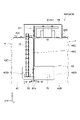
- FIG. 8A is a cross-sectional view of the track at the position where the first inspection device is arranged, viewed from the front in the running direction.
- FIG. 8(B) is a diagram showing the arrangement of the first guidance guide and the second guidance guide arranged on the track in the vicinity of the arrangement position of the first inspection device.
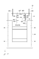
- FIG. 9(A) is a perspective view of the third inspection device when the first target plate and the second target plate are in the retracted state.
- FIG. 9B is a perspective view of the third inspection device when the first target plate and the second target plate are in the advanced state.
- FIG. 10 is a front view of the third inspection device seen from the inspection position.
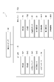
- FIG. 11 is a block diagram showing the functional configuration of the track guided vehicle system.
- the track guided vehicle system 1 uses an overhead traveling vehicle (carriage) 6 (hereinafter referred to as "traveling vehicle 6") that can move along a track 4 to transport articles.
- 10 is a system for transporting
- the article 10 includes, for example, a FOUP (Front Opening Unified Pod) for storing a plurality of semiconductor wafers, a container such as a reticle pod for storing a glass substrate, general parts, and the like.
- the track guided vehicle system 1 includes a track 4 , a plurality of traveling vehicles 6 , a plurality of placement sections 9 , an inspection unit 100 and a transport controller 90 .
- the track 4 is laid, for example, near the ceiling, which is the overhead space of the worker.
- the track 4 is suspended from the ceiling, for example.
- the track 4 is a predetermined travel path for the traveling vehicle 6 to travel.
- the track 4 is supported by struts 40A, 40A.
- the track 4 of the track-guided vehicle system 1 includes a main track portion 4A where the traveling vehicle 6 circulates in one direction D1 in a predetermined area, and a retreat portion 4B where the traveling vehicle 6 is introduced into an inspection unit 100 for inspecting the traveling vehicle 6. and have Note that the traveling vehicle 6 also moves in the predetermined one direction D1 in the retraction section 4B.
- the track 4 has a pair of lower surface portions 40B, 40B, a pair of side surface portions 40C, 40C, and a top surface portion 40D. 40F.
- the rail body portion 40 forms an internal space A1 partitioned from an external space A2.
- the internal space A1 extends along the direction in which the track 4 extends.
- the rail body portion 40 accommodates a traveling portion 50 of the traveling vehicle 6, which will be described in detail later.
- the lower surface portion 40 ⁇ /b>B extends in the traveling direction D ⁇ b>1 of the traveling vehicle 6 and constitutes the lower surface of the rail body portion 40 .
- the lower surface portion 40B is a plate-like member on which the traveling rollers 51 of the traveling vehicle 6 roll and on which the traveling vehicle 6 travels.
- the side surface portion 40 ⁇ /b>C extends in the traveling direction D ⁇ b>1 of the traveling vehicle 6 and constitutes the side surface of the rail body portion 40 .
- the top surface portion 40 ⁇ /b>D extends in the running direction D ⁇ b>1 of the traveling vehicle 6 and constitutes the top surface of the rail body portion 40 .
- the power supply unit 40E is a part that supplies electric power to the power supply core 57 of the traveling vehicle 6 and transmits and receives signals to and from the power supply core 57 .
- the power feeding portion 40E is fixed to each of the pair of side portions 40C, 40C and extends along the running direction D1.
- the power supply unit 40E supplies power to the power supply core 57 in a non-contact manner.
- the magnetic plate 40F causes the LDM (Linear DC Motor) 59 of the traveling vehicle 6 to generate magnetic force for traveling or stopping.
- the magnetic plate 40F is fixed to the top surface portion 40D and extends along the running direction D1.
- the traveling vehicle 6 travels along the track 4 and conveys the article 10.
- the traveling vehicle 6 is configured so that the article 10 can be transferred.
- the traveling vehicle 6 is an overhead traveling unmanned vehicle.
- the number of traveling vehicles 6 included in the track guided vehicle system 1 is not particularly limited, and is plural.
- the traveling vehicle 6 has a main body section 7 , a traveling section 50 and a main body controller 35 .
- the body portion 7 includes a body frame 22, a lateral feed portion 24, a .theta. and a sensor (obstacle detection unit) 34B.
- the body frame 22 is connected to the traveling section 50 and supports the lateral feed section 24, the ⁇ drive 26, the elevation drive section 28, the elevation table 30, and the cover 33.
- the traverse section 24 collectively traverses the .theta.
- the ⁇ drive 26 rotates at least one of the elevation drive unit 28 and the elevation table 30 within a predetermined angle range in the horizontal plane.
- the lift drive unit 28 lifts and lowers the lift table 30 by winding or feeding a suspension material such as a wire, rope, or belt.
- the lifting table 30 is provided with a chuck so that the article 10 can be freely grasped or released.
- a pair of covers 33 are provided, for example, on the front and rear sides of the traveling vehicle 6 in the traveling direction D1. The cover 33 prevents the article 10 from falling during transportation by allowing claws or the like (not shown) to appear and disappear.
- the collision prevention sensor 34A is provided above the front cover 33 of the pair of covers 33,33.
- the collision prevention sensor 34A emits light forward in the running direction D1, and detects the presence or absence of another traveling vehicle 6 located forward in the running direction D1 based on the presence or absence of detection of the reflected light. That is, the anti-collision sensor 34A has a light projecting portion and a light receiving portion.
- the obstacle sensor 34B is provided below the front cover 33 of the pair of covers 33,33.
- the obstacle sensor 34B emits light forward in the running direction D1, and detects the presence or absence of an obstacle located forward in the running direction D1 based on the presence or absence of detection of the reflected light. That is, the obstacle sensor 34B has a light projecting section and a light receiving section.
- the body controller 35 acquires detection results from the collision prevention sensor 34A and the obstacle sensor 34B.
- the traveling part 50 travels in the internal space A1 formed in the track 4 as described above.
- the traveling unit 50 mainly includes a traveling roller 51, a side roller 52, a light receiver (obstacle detection unit) 54A, a light projector (rear light projector) 54B (see FIGS. 3 and 4), a power supply core 57, and an LDM 59.
- the running roller 51 is a pair of rollers including an outer wheel as a running wheel and an inner wheel as an auxiliary running wheel.
- the running rollers 51 are arranged at both the front and rear left and right ends of the running portion 50 .
- the running rollers 51 roll on the pair of lower surface portions 40B, 40B of the track 4. As shown in FIG.
- the side rollers 52 are arranged so as to sandwich the outer rings of the running rollers 51 in the front-rear direction.
- the side roller 52 is provided so as to be able to contact the side surface portion 40C of the track 4 .
- the power supply cores 57 are arranged in front and behind the running portion 50, and are arranged so as to sandwich the LDM 59 in the left-right direction.
- the power supply unit 40 ⁇ /b>E arranged on the track 4 performs non-contact power supply and non-contact transmission/reception of various signals with the power supply core 57 .
- the power supply core 57 also exchanges signals with the body controller 35 .
- the LDM 59 is provided before and after the traveling portion 50 .
- the LDM 59 generates magnetic force for running or stopping between the magnetic plate 40F arranged on the upper surface of the track 4 by an electromagnet.
- the light receiver 54A is provided on the front surface of the traveling portion 50.
- the light receiver 54A receives light projected from a light projector 54B provided on a forward traveling vehicle 6 positioned within a predetermined distance from the own traveling vehicle 6 . In other words, the light receiver 54A cannot receive the light projected from the light projector 54B provided on the preceding vehicle 6 located outside the predetermined distance from the vehicle 6 .
- a detection result by the light receiver 54A is acquired by the body controller 35 .
- the body controller 35 determines that the traveling vehicle 6 exists within a predetermined distance ahead of the own traveling vehicle 6 when the light is received by the light receiver 54A.
- the light projector 54B is provided on the rear surface of the traveling portion 50.
- the light projector 54B projects light toward the rear of the vehicle 6 .
- the light projection distance of the light projector 54B is set so that the light receiver 54A provided in the following vehicle 6 located within a predetermined distance from the vehicle 6 can receive the light.
- Light projection by the light projector 54B is controlled by the body controller 35 .
- the traveling unit 50 is controlled via the body controller 35 by a transport controller (controller) 90 which will be described in detail later. Specifically, a command from the transport controller 90 is transmitted to the body controller 35 , and the body controller 35 that receives the command controls the traveling section 50 .
- the placing section 9 is arranged along the track 4 and provided at a position where the traveling vehicle 6 can transfer the article 10 .
- the receiver 9 includes a buffer and a transfer port.
- the buffer is a placement section on which the article 10 is temporarily placed. For example, when the article 10 being transported by the traveling vehicle 6 cannot be transferred to the target delivery port because another article 10 is placed on the target delivery port, the buffer This is a placement section for temporary placement.
- the delivery port is a placement for delivering the article 10 to a semiconductor processing apparatus (not shown) such as a cleaning apparatus, a film formation apparatus, a lithography apparatus, an etching apparatus, a heat treatment apparatus, and a planarization apparatus. Department. Note that the processing device is not particularly limited, and may be various devices.
- the placement section 9 is arranged on the side of the track 4 .
- the traveling vehicle 6 laterally feeds the elevation driving section 28 and the like by the lateral feeding section 24 and slightly raises and lowers the elevator table 30 to deliver the article 10 to and from the placement section 9 .
- the placement section 9 may be arranged directly below the track 4 . In this case, the traveling vehicle 6 transfers the articles 10 to and from the placement section 9 by raising and lowering the elevator platform 30 .
- the main body controller 35 is an electronic control unit consisting of a CPU (Central Processing Unit), ROM (Read Only Memory), RAM (Random Access Memory), and the like.
- the body controller 35 controls various operations in the traveling vehicle 6 . Specifically, the body controller 35 controls the traveling section 50 , the transverse feeding section 24 , the ⁇ drive 26 , the elevation drive section 28 , and the platform 30 .
- the body controller 35 can be configured as software in which, for example, a program stored in the ROM is loaded onto the RAM and executed by the CPU.
- the body controller 35 may be configured as hardware such as an electronic circuit.
- the body controller 35 communicates with the transport controller 90 by using the feeder 40E (feeder line) of the track 4 or the like.
- the inspection unit 100 is provided in a part of the evacuation section 4B, and as shown in FIGS. A device group for checking the operation of the sensor 34A and the obstacle sensor 34B.
- the inspection unit 100 includes a first inspection device 60A, a second inspection device 60B, and a third inspection device 80. As shown in FIG.
- the first inspection device 60A and the second inspection device 60B are arranged in the extending direction of the track 4 so as to sandwich an inspection position (predetermined position) P1 at which the traveling vehicle 6 stops when being inspected by the inspection unit 100. are placed in
- the first inspection device 60A is arranged at a position forward in the traveling direction D1 when viewed from the traveling vehicle 6 stopped at the inspection position P1.
- the distance between the inspection position P1 and the first inspection device 60A is, for example, about 2 m.
- the first inspection device 60A is a device for checking the operation of the light receiver 54A mounted on the traveling vehicle 6 stopped at the inspection position P1.
- the light projector (detected part) 70 of the first inspection device 60A advances into the traveling space of the traveling vehicle 6 during the inspection for confirming the operation of the light receiver 54A, and when the traveling vehicle 6 passes the advanced position of the light projector 70.
- the light projector 70 is provided movably between the internal space A1 and the external space A2, and as shown in FIG. As shown in (A), it is driven by the first drive section 64 (see FIG. 5) so as to retreat to the external space A2 during passage (normal time).
- the first inspection device 60A includes a plate member 61, a slide mechanism 63, a first drive section 64, a lower connection member 65, an upper connection member 66, a light projector 70 And prepare.
- the plate member 61 is formed in a plate shape.
- the plate-like member 61 is provided so as to be able to pass through the X-direction gap 40G formed in the track 4 .
- the size of the gap 40G is, for example, 5 mm, and the plate member 61 is formed to have a thickness that allows it to be inserted into the gap 40G.
- the gap 40G may be formed by connecting the tracks 4, 4 with a gap in the X direction, for example.
- the connection of the tracks 4 , 4 is performed using, for example, a lower connecting member 65 and an upper connecting member 66 .
- the plate-shaped member 61 is connected to a slide mechanism 63 arranged on the top surface portion 40D of the track 4.
- the slide mechanism 63 is, for example, a linear guide, and supports the plate member 61 having a main surface in the X direction so as to be movable in the Y direction.
- a pair of guide rollers 65A, 65A provided on the lower connecting member 65.
- the guide rollers 65A, 65A are made of resin, for example. Since the lower connection member 65 having such guide rollers 65A, 65A is provided at three locations along the Y direction, the plate-like member 61 moved in the Y direction by the slide mechanism 63 is located in the gap of the track 4.
- the portion 40G can be moved smoothly. Further, one lower connecting member 65 having only the function of connecting the track 4 without having the guide rollers 65A, 65A is provided.
- the slide mechanism 63 is driven by the first driving section 64 .
- the first drive unit 64 is provided so as to communicate with a transport controller 90 (see FIG. 11) and is controlled by the transport controller 90 .
- the light projector 70 is movable between the internal space A1 and the external space A2 by being attached to the plate member 61 as described above.
- the light projector 70 is attached so as to protrude toward the inspection position P1.
- the light projector 70 is connected to a control box (not shown) arranged on the top surface 40 ⁇ /b>D of the track 4 or the like via a cable 72 housed in a cable guide 75 .
- the control box is provided so as to communicate with the transport controller 90 .
- the light projector 70 is supplied with power necessary for operation through a cable 72 and communicates with a transport controller 90 through the cable 72 .
- a side surface 40C of the track 4 has a notch that allows the projector 70 attached to the plate member 61 to move between the internal space A1 and the external space A2.
- 40W is provided.
- the plate-like member 61 is provided with a lid portion 62 that covers an area through which the light projector 70 passes in the notch portion 40W when the light projector 70 advances into the internal space A1. ing. That is, when the light projector 70 advances into the internal space A1, the lid portion 62 shields the space formed by the notch portion 40W and communicating between the internal space A1 and the external space A2.
- the space between the traveling vehicle 6 and the plate-like member 61 receives disturbance from the external space. It can prevent light from entering.
- a side surface portion 40C (inner surface) of the track 4 is provided with a first guide 40K and a second guide 40L.
- the first guide 40K has a side surface 40Ka with which the side roller 52 contacts.
- the first guiding guide 40K is provided on the left side portion 40C in the traveling direction D1.
- the side surface 40Ka has a portion that guides the side rollers 52 (that is, the traveling vehicle 6) to the right in the running direction D1 toward the gap 40G, and and a portion that guides the side roller 52 to the left in the running direction D1.
- the second guide 40L has a side surface 40La that contacts the side roller 52.
- the second guide 40L is provided on the right side portion 40C in the running direction D1 (X direction).
- the second guiding guide 40L guides the side roller 52 to the left in the running direction D1 by the side 40Ka from the position where the side roller 52 has been guided to the right in the running direction D1 by the side 40Ka. is extended to the position where is induced.
- the traveling part 50 traveling on the track 4 having the first guiding guide 40K and the second guiding guide 40L is guided to the right side of the internal space A1 at the inspection position P1.
- the side rollers 52 are prevented from protruding from the notch portion 40W provided in the left side portion 40C in the running direction D1.
- the first guiding guide 40K and the second guiding guide 40L guide (position) the traveling portion 50 so that the light projected from the light projector 70 can be received by the light receiver 54A, and will be described in detail later.
- the traveling portion 50 is guided (positioned) so that the light emitted from the light emitter 54B is received by the light receiver (light emitter detection portion) 70B.
- the first guiding guide 40K and the second guiding guide 40L are divided across the gap 40G so as not to hinder the movement of the plate-like member 61 in the inner space A1 of the track 4 (Fig. 8(B)).
- the power supply unit 40E must have a similar configuration.
- the power feeding portion 40E is separated across the gap 40G, and terminal boxes 40T are provided in front of and behind the gap 40G in the X direction, as shown in FIG. Then, the cables C and the like that constitute the power supply portion 40E are pulled out from the terminal box 40T to the external space A2 of the track 4, and these cables C are connected in the external space A2.
- the second inspection device 60B is arranged at a position behind in the traveling direction D1 when viewed from the traveling vehicle 6 stopped at the inspection position P1.
- the distance between the inspection position P1 and the second inspection device 60B is, for example, about 2 m.
- the second inspection device 60B is a device for checking the operation of the light projector 54B mounted on the traveling vehicle 6 stopped at the inspection position P1.
- the light receiver 70B of the second inspection device 60B advances into the traveling space of the traveling vehicle 6 at the time of inspection for confirming the operation of the light emitter 54B, and when the traveling vehicle 6 passes through the advance position of the light receiver 70B ( It is configured to be movable so as to be retracted from the traveling space of the traveling vehicle 6 when passing without checking the operation.
- the photodetector 70B of the second inspection device 60B is provided movably between the internal space A1 and the external space A2, advances into the internal space A1 during inspection, and moves into the external space A2 during passage. It is driven by the second driving section 64B so as to retreat.
- the configuration of the second inspection device 60B is similar to the configuration of the first inspection device 60A mainly described using FIGS. That is, the second inspection device 60B differs from the first inspection device 60A in that a light receiver 70B is provided instead of the light projector 70, but the light receiver 70B is moved between the inner space A1 and the outer space A2.
- the enabling configuration is the same as the first inspection device 60A. That is, the second inspection device 60B includes a plate-like member 61B, a slide mechanism 63B, a second drive section 64B, a lower connection member 65, and an upper connection member 66.
- the second inspection device 60B also has a cable 72 and a cable guide 75 connected to the light receiver 70B.
- the first inspection device 60A and the second inspection device 60B have opposite left and right positional relationships (symmetrical about the inspection position P1 as the center line) when viewed from the side (Y direction). different in that Here, detailed description of each part constituting the second inspection device 60B is omitted.
- the internal space A1 between the traveling vehicle 6 and the plate-shaped member 61B of the second inspection device 60B (in other words, the internal space A1 between the light projector 54B and the light receiver 70B It is possible to prevent disturbance light from entering from the external space A2 into the space through which the light projected from the light projector 54B passes. More specifically, it is possible to prevent ambient light from entering the internal space A1 between the plate member 61 of the first inspection device 60A and the plate member 61B of the second inspection device 60B from the external space A2.
- the third inspection device 80 is arranged at a position forward in the traveling direction D1 when viewed from the traveling vehicle 6 stopped at the inspection position P1.
- the distance between the inspection position P1 and the third inspection device 80 is, for example, about 3 m.
- the third inspection device 80 is a device that checks the operation of the collision prevention sensor 34A and the obstacle sensor 34B mounted on the traveling vehicle 6 stopped at the inspection position P1.
- a first target plate (detected portion/reflecting member) 84 of the third inspection device 80 advances into the traveling space of the traveling vehicle 6 during an inspection for confirming the operation of the anti-collision sensor 34A, and the first target plate 84 advances.
- a second target plate (detected portion/reflecting member) 85 of the third inspection device 80 advances into the traveling space of the traveling vehicle 6 during an inspection for confirming the operation of the obstacle sensor 34B, and the second target plate 85 advances. It is configured to be movable so as to be retracted from the traveling space of the traveling vehicle 6 when the traveling vehicle 6 passes through the position (normal time when the operation of the obstacle sensor 34B is not confirmed).
- the third inspection device 80 includes a fixed portion 81, a frame-shaped body portion 82, a first target plate 84, a second target plate 85, a left slide mechanism 87, a third drive section 88, a right slide mechanism 87A, a fourth drive section 88A, and a third target plate 89.
- a fixed portion 81 As shown in FIGS. 9A, 9B, and 10, the third inspection device 80 includes a fixed portion 81, a frame-shaped body portion 82, a first target plate 84, a second target plate 85, a left slide mechanism 87, a third drive section 88, a right slide mechanism 87A, a fourth drive section 88A, and a third target plate 89.
- the fixed part 81 is fixed to the ceiling or the track 4, and supports the frame-shaped main body part 82 in a suspended state.
- the frame-shaped body portion 82 is formed so as to enclose the traveling space of the traveling vehicle 6 so that the traveling vehicle 6 can pass therethrough when viewed from the X direction of the traveling vehicle 6 .
- a reflective sticker similar to the reflective sticker attached to at least a part of the rear cover 33 of the traveling vehicle 6 is attached to the first target plate 84 .
- the first target plate 84 reflects the light projected from the anti-collision sensor 34A by a reflective seal.
- the light projected from the collision prevention sensor 34A is reflected only by the reflective seal and is not reflected by other members.
- the second target plate 85 reflects light projected from the obstacle sensor 34B.
- the first target plate 84 is connected to a left slide mechanism 87 arranged on the left side of the frame-shaped body portion 82 when the third inspection device 80 is viewed from the inspection position P1.
- the left slide mechanism 87 is, for example, a linear guide, and supports the first target plate 84 movably in the Z direction.
- the left slide mechanism 87 is driven by the third driving section 88 .
- the third drive unit 88 is provided so as to communicate with a transport controller 90 (see FIG. 11) and is controlled by the transport controller 90 .
- the first target plate 84 is attached to such a left slide mechanism 87 so that it can move with respect to the traveling space of the traveling vehicle 6 .
- the first target plate 84 retreats below the travel space.
- the second target plate 85 is connected to a right slide mechanism 87A arranged on the right side of the frame-shaped body portion 82 when the third inspection device 80 is viewed from the inspection position P1.
- the right slide mechanism 87A is, for example, a linear guide, and supports the second target plate 85 movably in the Z direction.
- the right slide mechanism 87A is driven by the fourth drive section 88A.
- the fourth drive unit 88A is provided so as to be able to communicate with the transport controller 90 (see FIG. 11) and is controlled by the transport controller 90.
- the second target plate 85 is attached to such a right slide mechanism 87A so that it can move with respect to the traveling space of the traveling vehicle 6 .
- the second target plate 85 retreats below the travel space.
- the first target plate 84 and the second target plate 85 are configured to retract to the lower part of the travel space by their own weight when power is not supplied to the third inspection device 80 for some reason (for example, a power failure). It is At the retracted positions of the first target plate 84 and the second target plate 85, a buffer member is provided to reduce the impact caused by the weight of the first target plate 84 and the second target plate 85 when they are dropped.
- the third target plate 89 is a flat member provided on the side where the traveling vehicle 6 enters.
- the third target plate 89 is configured to be able to reflect the light projected from the anti-collision sensor 34A.
- a reflective sticker is attached to at least a portion of the third target plate 89 .
- the position detection sensor 83 detects the positions of the first target plate 84 and the second target plate 85 . That is, the position detection sensor 83 detects whether or not the first target plate 84 and the second target plate 85 have advanced into the traveling space of the traveling vehicle 6 . A detection result by the position detection sensor 83 is acquired by the transport controller 90 .
- the transport controller 90 controls a plurality of traveling vehicles 6 traveling on the track 4 via the main body controller 35 . Further, the transport controller 90 controls the light projector 70, the light receiver 70B, the position detection sensor 83, the first drive section 64, the second drive section 64A, the third drive section 88 and the fourth drive section 88A included in the inspection unit 100. do.
- the transport controller 90 causes the traveling vehicle 6 to travel to the inspection unit 100 with a predetermined condition as a trigger.
- the predetermined condition is, for example, when an operator inputs an inspection start command via an input unit (not shown), when a traveling vehicle 6 appears after a predetermined period of time has passed since the previous inspection, or when the vehicle 6 has passed since the previous inspection. For example, when a traveling vehicle 6 that has traveled a predetermined distance appears, the transport controller 90 causes the traveling vehicle 6 that meets the conditions to travel to the inspection position P ⁇ b>1 of the inspection unit 100 .
- the transport controller 90 controls the first driving section 64 to advance the projector 70 of the first inspection device 60A into the internal space A1, and controls the second driving section 64A. Then, the light receiver 70B of the second inspection device 60B is advanced into the internal space A1.
- the transport controller 90 controls the light projector 70 of the first inspection device 60A to emit light.
- the transport controller 90 determines the state of the light receiver 54A based on the detection result of the light receiver 54A of the traveling vehicle 6 at this time. That is, if the light can be detected, it is determined that the light receiver 54A of the traveling vehicle 6 is normal, and if the light cannot be detected, it is determined that the light receiver 54A of the traveling vehicle 6 is abnormal.
- the transport controller 90 controls the light projector 54B of the traveling vehicle 6 via the main body controller 35 to emit light.
- the transport controller 90 determines the state of the light projector 54B based on the detection result of the light receiver 70B of the second inspection device 60B at this time. That is, if the light receiver 70B of the second inspection device 60B can detect light, it is determined that there is no abnormality in the light projector 54B of the traveling vehicle 6, and if the light receiver 70B of the second inspection device 60B cannot detect light, It is determined that there is an abnormality in the light projector 54B.
- the transport controller 90 controls the third drive section 88 to advance the first target plate 84 into the traveling space of the traveling vehicle 6, and controls the fourth drive section 88A to move the second target plate 85. It advances into the traveling space of the traveling vehicle 6. - ⁇ The transport controller 90 controls the collision prevention sensor 34A of the traveling vehicle 6 to emit light. The transport controller 90 determines the state of the collision prevention sensor 34A based on the detection result of the collision prevention sensor 34A at this time. That is, if light can be detected, it is determined that there is no abnormality in the collision prevention sensor 34A, and if light cannot be detected, it is determined that there is an abnormality in the collision prevention sensor 34A.
- the amount of light received by the anti-collision sensor 34A changes depending on the amount of light reflected by the first target plate 84 and the third target plate 89 from the light projected from the anti-collision sensor 34A. Based on the amount of light received by the collision prevention sensor 34A, the transport controller 90 determines whether or not the optical axis of the collision prevention sensor 34A is misaligned in the horizontal direction.
- the transport controller 90 controls the obstacle sensor 34B of the traveling vehicle 6 to emit light.
- the transport controller 90 determines the state of the obstacle sensor 34B based on the detection result of the obstacle sensor 34B at this time. That is, if light can be detected, it is determined that the obstacle sensor 34B is normal, and if light cannot be detected, it is determined that the obstacle sensor 34B is abnormal.
- the transport controller 90 determines that at least one of the first target plate 84 and the second target plate 85 has advanced into the traveling space of the traveling vehicle 6 based on the detection result of the position detection sensor 83, the traveling vehicle 6 are prohibited from entering the third inspection device 80.
- the track guided vehicle system 1 of the above embodiment when inspecting the state of the light receiver 54A of the traveling vehicle 6 positioned at the inspection position P1, the projector 70 is advanced in front of the traveling space of the traveling vehicle 6.
- the state of the photodetector 54A is determined based on the result of detection by the photodetector 54A. Further, when the traveling vehicle 6 passes through the advance position of the light projector 70, the light projector 70 is retracted from the traveling space of the traveling vehicle 6, so that the traveling of the traveling vehicle 6 is not hindered.
- the first target plate 84 is advanced in front of the traveling space of the traveling vehicle 6, and based on the detection result by the collision prevention sensor 34A at this time, The state of the anti-collision sensor 34A is determined.
- the second target plate 85 is advanced in front of the traveling space of the traveling vehicle 6, and based on the detection result of the obstacle sensor 34B at this time, the obstacle sensor 34B state is determined. Therefore, it is possible to automatically check the operation of the light receiver 54A, the light receivers 54A and 54A, and the obstacle sensor 34B provided in the vehicle 6 traveling on the track 4.
- the light projector 70 is provided movably between the internal space A1 and the external space A2. do. With such a configuration, it is possible to automatically check the operation of the light projector 70 attached to the traveling section 50 that travels in the inner space A1 of the track 4 .
- the notch 40W is covered with the lid 62 when the light projector 70 advances into the internal space A1 of the track 4, so ambient light or the like enters the internal space A1 from the external space A2. is prevented. As a result, the operation of the light projector 70 can be confirmed more reliably without being affected by disturbance light.
- the light receiver 70B appears behind the traveling vehicle 6 at the time of inspection for checking the state of the light projector 54B of the traveling vehicle 6 positioned at the inspection position P1.
- the state of the light projector 54B is determined based on the result of detection by. As a result, it is possible to automatically check the operation of the light projector 54B provided on the traveling vehicle 6 traveling on the track 4 .
- the light receiver 54A for receiving the light projected from the forward traveling vehicle 6 is provided on the front surface of the traveling section 50
- a forward sensor with receiver and projector may be provided.
- a target plate capable of reflecting light projected from the front sensor is provided.
- a sensor having the same configuration as the front sensor may be provided on the rear surface of the traveling portion 50 .
- the traveling section 50 may be provided with a distance sensor or the like instead of the above-described sensor.
- the target plate is applied to the first inspection device 60A.
- the inspection unit 100 is arranged in the retraction section 4B retracted from the main line section 4A. However, it may be provided in the main line section 4A. .
- control of the traveling vehicle 6 during inspection including control of each configuration of the inspection unit 100
- the transport controller 90 executes control of the traveling vehicle 6 during inspection, including control of each component of the inspection unit 100 .
- the overhead traveling vehicle 6 was used as an example of a vehicle. This includes unmanned vehicles, etc.
- SYMBOLS 1 Track-guided truck system, 4... Track, 6... Overhead traveling vehicle (carriage), 34A... Collision prevention sensor (obstacle detection part), 34B... Obstacle sensor (obstacle detection part), 35... Main body controller, 40W Notch portion 50 Traveling portion 54A Photoreceiver (obstacle detection portion) 54B Projector (rear projector) 60A First inspection device 60B Second inspection device 61 Plate member 62 Lid part 70... Light emitter (detected part) 70B... Light receiver (light emitter detection part) 80... Third inspection device 82... Frame-shaped main body 84... First target plate (detected part/reflective member) , 85... Second target plate (part to be detected/reflecting member), 90... Conveyance controller (controller), 100... Inspection unit, A1... Internal space, A2... External space, D1... Running direction, P1... Inspection position (predetermined position).
Landscapes
- Engineering & Computer Science (AREA)
- Transportation (AREA)
- Mechanical Engineering (AREA)
- Control Of Position, Course, Altitude, Or Attitude Of Moving Bodies (AREA)
- Platform Screen Doors And Railroad Systems (AREA)
Abstract
Ce système de support guidé par rail (1) comprend une partie détectée (70, 84, 85) qui est disposée devant un support (6) positionné à une position prédéterminée (P1) dans une direction de déplacement (D1) du support (6) et est détectée par une partie de détection d'obstacle (54A, 34A, 34B) et un dispositif de commande (90) qui détermine l'état de la partie de détection d'obstacle (54A, 34A, 34B) sur la base d'un résultat de détection pour la partie détectée (70, 84, 85) par la partie de détection d'obstacle (54A, 34A, 34B). La partie détectée (70, 84, 85) est prévue pour se déplacer de façon à avancer jusqu'à un espace de déplacement du support (6) lors de l'inspection pour vérifier le fonctionnement de la partie de détection d'obstacle (54A, 34A, 34B) et de façon à se rétracter à partir de l'espace de déplacement du support (6) lorsque le support (6) passe à travers la position avancée de la partie détectée (70, 84, 85).
Priority Applications (2)
| Application Number | Priority Date | Filing Date | Title |
|---|---|---|---|
| CN202280028994.0A CN117157221A (zh) | 2021-06-16 | 2022-03-16 | 有轨台车系统 |
| JP2023529562A JPWO2022264579A1 (fr) | 2021-06-16 | 2022-03-16 |
Applications Claiming Priority (2)
| Application Number | Priority Date | Filing Date | Title |
|---|---|---|---|
| JP2021099980 | 2021-06-16 | ||
| JP2021-099980 | 2021-06-16 |
Publications (1)
| Publication Number | Publication Date |
|---|---|
| WO2022264579A1 true WO2022264579A1 (fr) | 2022-12-22 |
Family
ID=84527023
Family Applications (1)
| Application Number | Title | Priority Date | Filing Date |
|---|---|---|---|
| PCT/JP2022/012017 WO2022264579A1 (fr) | 2021-06-16 | 2022-03-16 | Système de support guidé par rail |
Country Status (4)
| Country | Link |
|---|---|
| JP (1) | JPWO2022264579A1 (fr) |
| CN (1) | CN117157221A (fr) |
| TW (1) | TW202301057A (fr) |
| WO (1) | WO2022264579A1 (fr) |
Citations (2)
| Publication number | Priority date | Publication date | Assignee | Title |
|---|---|---|---|---|
| JP2019049447A (ja) * | 2017-09-08 | 2019-03-28 | 株式会社ダイフク | 検査システム |
| JP2020143983A (ja) * | 2019-03-06 | 2020-09-10 | 株式会社ダイフク | 検査システム |
-
2022
- 2022-03-16 WO PCT/JP2022/012017 patent/WO2022264579A1/fr active Application Filing
- 2022-03-16 JP JP2023529562A patent/JPWO2022264579A1/ja active Pending
- 2022-03-16 CN CN202280028994.0A patent/CN117157221A/zh active Pending
- 2022-06-15 TW TW111122146A patent/TW202301057A/zh unknown
Patent Citations (2)
| Publication number | Priority date | Publication date | Assignee | Title |
|---|---|---|---|---|
| JP2019049447A (ja) * | 2017-09-08 | 2019-03-28 | 株式会社ダイフク | 検査システム |
| JP2020143983A (ja) * | 2019-03-06 | 2020-09-10 | 株式会社ダイフク | 検査システム |
Also Published As
| Publication number | Publication date |
|---|---|
| JPWO2022264579A1 (fr) | 2022-12-22 |
| CN117157221A (zh) | 2023-12-01 |
| TW202301057A (zh) | 2023-01-01 |
Similar Documents
| Publication | Publication Date | Title |
|---|---|---|
| CN107291076B (zh) | 物品输送设备 | |
| KR100729986B1 (ko) | 자동반송시스템 | |
| KR102463268B1 (ko) | 물품 반송 설비, 및 물품 반송차 | |
| JP2018128914A (ja) | 物品搬送設備 | |
| TWI636935B (zh) | Temporary storage device for carrier and temporary storage method | |
| KR101733717B1 (ko) | 반송 시스템 | |
| JP2006323435A (ja) | 搬送台車の障害物検出装置 | |
| TWI636936B (zh) | Temporary storage device and storage method of vehicle | |
| KR102535709B1 (ko) | 검사 시스템 | |
| KR20190141086A (ko) | 물품 반송 설비 | |
| WO2022264579A1 (fr) | Système de support guidé par rail | |
| JP7380637B2 (ja) | 有軌道台車 | |
| JP4887804B2 (ja) | 搬送システム | |
| CN113557487B (zh) | 输送车系统 | |
| JP4352925B2 (ja) | 無人搬送車のセンサ制御装置及び無人搬送システム | |
| CN113906359A (zh) | 行驶系统 | |
| WO2023037773A1 (fr) | Système de véhicule de déplacement et véhicule de déplacement | |
| JP7480797B2 (ja) | 天井搬送車システム | |
| WO2023032293A1 (fr) | Système de véhicule en déplacement | |
| WO2022113529A1 (fr) | Étagère de stockage et système de cabine de transport de plafond | |
| JP3496823B2 (ja) | トラックへの荷積みシステム | |
| JP4093206B2 (ja) | 搬送車システム | |
| KR102436163B1 (ko) | 이송 시스템 및 이송 시스템의 운영방법 | |
| KR20120018990A (ko) | 수하물 운송장치 | |
| JP3555079B2 (ja) | 有軌道台車システム |
Legal Events
| Date | Code | Title | Description |
|---|---|---|---|
| 121 | Ep: the epo has been informed by wipo that ep was designated in this application |
Ref document number: 22822857 Country of ref document: EP Kind code of ref document: A1 |
|
| WWE | Wipo information: entry into national phase |
Ref document number: 2023529562 Country of ref document: JP |
|
| WWE | Wipo information: entry into national phase |
Ref document number: 18287479 Country of ref document: US |
|
| NENP | Non-entry into the national phase |
Ref country code: DE |