WO2022254705A1 - 空調システム - Google Patents
空調システム Download PDFInfo
- Publication number
- WO2022254705A1 WO2022254705A1 PCT/JP2021/021407 JP2021021407W WO2022254705A1 WO 2022254705 A1 WO2022254705 A1 WO 2022254705A1 JP 2021021407 W JP2021021407 W JP 2021021407W WO 2022254705 A1 WO2022254705 A1 WO 2022254705A1
- Authority
- WO
- WIPO (PCT)
- Prior art keywords
- fan
- air
- room
- pressure
- clean room
- Prior art date
- Legal status (The legal status is an assumption and is not a legal conclusion. Google has not performed a legal analysis and makes no representation as to the accuracy of the status listed.)
- Ceased
Links
Images





Classifications
-
- F—MECHANICAL ENGINEERING; LIGHTING; HEATING; WEAPONS; BLASTING
- F24—HEATING; RANGES; VENTILATING
- F24F—AIR-CONDITIONING; AIR-HUMIDIFICATION; VENTILATION; USE OF AIR CURRENTS FOR SCREENING
- F24F11/00—Control or safety arrangements
- F24F11/70—Control systems characterised by their outputs; Constructional details thereof
- F24F11/72—Control systems characterised by their outputs; Constructional details thereof for controlling the supply of treated air, e.g. its pressure
- F24F11/74—Control systems characterised by their outputs; Constructional details thereof for controlling the supply of treated air, e.g. its pressure for controlling air flow rate or air velocity
- F24F11/77—Control systems characterised by their outputs; Constructional details thereof for controlling the supply of treated air, e.g. its pressure for controlling air flow rate or air velocity by controlling the speed of ventilators
-
- F—MECHANICAL ENGINEERING; LIGHTING; HEATING; WEAPONS; BLASTING
- F24—HEATING; RANGES; VENTILATING
- F24F—AIR-CONDITIONING; AIR-HUMIDIFICATION; VENTILATION; USE OF AIR CURRENTS FOR SCREENING
- F24F11/00—Control or safety arrangements
- F24F11/70—Control systems characterised by their outputs; Constructional details thereof
- F24F11/72—Control systems characterised by their outputs; Constructional details thereof for controlling the supply of treated air, e.g. its pressure
-
- F—MECHANICAL ENGINEERING; LIGHTING; HEATING; WEAPONS; BLASTING
- F24—HEATING; RANGES; VENTILATING
- F24F—AIR-CONDITIONING; AIR-HUMIDIFICATION; VENTILATION; USE OF AIR CURRENTS FOR SCREENING
- F24F3/00—Air-conditioning systems in which conditioned primary air is supplied from one or more central stations to distributing units in the rooms or spaces where it may receive secondary treatment; Apparatus specially designed for such systems
- F24F3/12—Air-conditioning systems in which conditioned primary air is supplied from one or more central stations to distributing units in the rooms or spaces where it may receive secondary treatment; Apparatus specially designed for such systems characterised by the treatment of the air otherwise than by heating and cooling
- F24F3/16—Air-conditioning systems in which conditioned primary air is supplied from one or more central stations to distributing units in the rooms or spaces where it may receive secondary treatment; Apparatus specially designed for such systems characterised by the treatment of the air otherwise than by heating and cooling by purification, e.g. by filtering; by sterilisation; by ozonisation
- F24F3/167—Clean rooms, i.e. enclosed spaces in which a uniform flow of filtered air is distributed
-
- F—MECHANICAL ENGINEERING; LIGHTING; HEATING; WEAPONS; BLASTING
- F24—HEATING; RANGES; VENTILATING
- F24F—AIR-CONDITIONING; AIR-HUMIDIFICATION; VENTILATION; USE OF AIR CURRENTS FOR SCREENING
- F24F7/00—Ventilation
- F24F7/04—Ventilation with ducting systems, e.g. by double walls; with natural circulation
- F24F7/06—Ventilation with ducting systems, e.g. by double walls; with natural circulation with forced air circulation, e.g. by fan positioning of a ventilator in or against a conduit
-
- F—MECHANICAL ENGINEERING; LIGHTING; HEATING; WEAPONS; BLASTING
- F24—HEATING; RANGES; VENTILATING
- F24F—AIR-CONDITIONING; AIR-HUMIDIFICATION; VENTILATION; USE OF AIR CURRENTS FOR SCREENING
- F24F2110/00—Control inputs relating to air properties
- F24F2110/40—Pressure, e.g. wind pressure
-
- Y—GENERAL TAGGING OF NEW TECHNOLOGICAL DEVELOPMENTS; GENERAL TAGGING OF CROSS-SECTIONAL TECHNOLOGIES SPANNING OVER SEVERAL SECTIONS OF THE IPC; TECHNICAL SUBJECTS COVERED BY FORMER USPC CROSS-REFERENCE ART COLLECTIONS [XRACs] AND DIGESTS
- Y02—TECHNOLOGIES OR APPLICATIONS FOR MITIGATION OR ADAPTATION AGAINST CLIMATE CHANGE
- Y02B—CLIMATE CHANGE MITIGATION TECHNOLOGIES RELATED TO BUILDINGS, e.g. HOUSING, HOUSE APPLIANCES OR RELATED END-USER APPLICATIONS
- Y02B30/00—Energy efficient heating, ventilation or air conditioning [HVAC]
- Y02B30/70—Efficient control or regulation technologies, e.g. for control of refrigerant flow, motor or heating
Definitions
- Patent Literature 1 describes "... individually controlling the air supply fan 22 of each FFU 20 so as to maintain the differential pressure measured by the differential pressure gauge 25 within a predetermined range".
- a user-friendly air conditioning system can be provided.
- FIG. 4 is an explanatory diagram showing the arrangement and the like of a plurality of fan filter units provided in the air conditioning system according to the first embodiment
- FIG. 4 is an explanatory diagram showing the arrangement and the like of a plurality of fan filter units provided in the air conditioning system according to the first embodiment
- FIG. 3 is a configuration diagram related to control of a fan filter unit on the supply air side and a fan filter unit on the return air side provided in the air conditioning system according to the first embodiment
- FIG. 4 is a characteristic diagram showing the relationship between the rotational speed of a return air fan provided in the air conditioning system according to the first embodiment and the air volume; It is an explanatory view of an air-conditioning system concerning a 2nd embodiment.
- FIG. 1 is an explanatory diagram showing the layout of each room in an air conditioning system S according to the first embodiment.
- the direction in which air flows when a predetermined door (for example, door Dm) is opened is indicated by an outline dashed arrow.
- the adjustment of the room pressure in each clean room will be mainly described, but the "air conditioning” also includes the adjustment of the temperature and humidity of the air in addition to the room pressure. In addition, adjustment of room pressure alone is also included in "air conditioning.”
- the air conditioning system S is a system that adjusts the room pressure of multiple clean rooms such as the pretreatment room R3 and the preparation room R7, and is installed in regenerative medicine facilities, for example.
- a plurality of rooms with different air cleanliness levels are often provided.
- a difference is provided between the room pressures of adjacent rooms.
- the pretreatment room R3 shown in FIG. 1 has higher air cleanliness and higher room pressure than the primary changing room R2. Therefore, when the worker opens the door De when entering the pretreatment room R3 from the primary changing room R2, as indicated by the dashed arrow in FIG. Air flows into R2, but rarely reverses. This prevents dust from entering the pretreatment room R3 from the primary changing room R2, and maintains the cleanliness of the pretreatment room R3.
- a dressing room R1, a primary dressing room R2, a pretreatment room R3, a dressing room R10, and an antechamber R11 are provided adjacent to each other in this order.
- the pretreatment chamber R3 is provided with a biohazard cabinet BSC1 for handling predetermined samples.
- a sample to be used in the biohazard cabinet BSC1 is carried in through the antechamber R4 and the pass box PB1 in sequence.
- the products (processed cell products, etc.) produced in the biohazard cabinet BSC1 are carried out through the pass box PB2 and the anteroom R5 in sequence.
- the pass boxes PB1 and PB2 are spaces for suppressing contamination (sample contamination).
- a dressing room R1, a primary dressing room R2, a secondary dressing room R6, an air lock AL1, a preparation room R7, an air lock AL2, a dressing room R10, and an antechamber R11 are arranged next to each other in this order.
- the airlocks AL1 and AL2 are spaces for suppressing dust from entering the preparation room R7, which has a high degree of cleanliness, and have a higher room pressure than other clean rooms.
- biohazard cabinets BSC2 and BSC3 for handling predetermined samples are provided in preparation room R7.
- Products (processed cell products, etc.) produced in the biohazard cabinets BSC2 and BSC3 are carried out through the pass box PB3 and the front chamber R8 in sequence.
- wastes and the like are carried out through the pass box PB4 and the anteroom R9 in sequence.
- airlocks AL1 and AL2 each correspond to a "clean room".
- the air handling unit 50 will be described later.
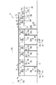
- FIG. 2 is an explanatory diagram showing the arrangement and the like of a plurality of fan filter units.
- solid arrows indicate air flow
- broken arrows indicate signal lines.
- 2 shows a part of each clean room of FIG. 1 (floor plan)
- FIG. 3 shows the rest of the clean room.
- 2 and 3 are schematic cross-sectional views focusing on the flow of air, for example, air is led from the preparation chamber R7 to the chamber C via the duct shaft DS2.
- the outlet of the fan 53 and the chamber C are connected via a duct D1.
- the duct D ⁇ b>1 is an air conduit that guides the air, the temperature of which has been adjusted by the air handling unit 50 , to the chamber C.
- a damper B1 is provided in the duct D1. Then, for example, the damper B1 is set to a predetermined degree of opening during trial operation of the air conditioning system S, and is maintained at the predetermined degree of opening during subsequent air conditioning operation.
- air whose temperature and the like have been adjusted is led to the chamber C via another duct D2.
- the air supplied via ducts D1 and D2 joins in chamber C.
- the fan filter unit 1 (first unit) shown in FIG. 2 is a device that supplies air from the chamber C to the preparation room R7, and is embedded in the ceiling E.
- the fan filter unit 1 includes an air supply fan 1a (first fan) and a filter 1b.
- the air supply fan 1a is a blower that supplies air from the chamber C to the preparation room R7 (clean room). As shown in FIG. 2, the suction side of the air supply fan 1a communicates with the chamber C (common space).
- the filter 1b collects dust from the air flowing from the air supply fan 1a toward the preparation chamber R7, and is provided on the blowout side of the air supply fan 1a.
- a filter 1b for example, HEPA (High Efficiency Particulate Air Filter) or ULPA (Ultra Low Penetration Air Filter) is used.
- a housing (not shown) housing the air supply fan 1a and the filter 1b is fitted into the opening of the ceiling E of the preparation room R7 and fixed with metal fittings or the like.
- Another fan filter unit 2 provided on the ceiling E of the preparation room R7 has the same configuration as the fan filter unit 1 described above.
- the pressure sensor 31 shown in FIG. 2 is a sensor that detects the room pressure of the preparation room R7 (clean room), and is provided in the preparation room R7. Then, the air supply fans 1a and 2a and the return air fan 3a are controlled so that the room pressure of the preparation chamber R7 becomes a predetermined target pressure (set pressure).
- a predetermined target pressure set pressure
- the room pressure of a general room not shown
- a preset predetermined pressure value may be used as the reference pressure.
- the other gap K2 shown in FIG. 2 is, for example, between the packing (not shown) at the lower end of the door Dp separating the preparation room R7 and the space R12 (see FIG. 1) and the floor surface of the preparation room R7. It's a gap.
- the space R12 shown in FIG. 1 is provided on the suction side of the return air fan 3a (see FIG. 2) and communicates with the chamber C (see FIG. 2) via the duct shaft DS2 (see FIG. 2). .
- the height position of the lower end of the packing of the door Dp is adjustable so that the size of the gap K2 can be adjusted.
- the sizes (opening ratios) of the gaps K1 and K2 are appropriately adjusted at the time of design and trial operation of the air conditioning system S based on the volume of the preparation chamber R7, the number of ventilation times per unit time, the target pressure, and the like.
- the intake side of the supply air fan 1a (first fan) and the return air fan 3a respectively communicate with the chamber C (common space).
- the chamber C common space
- a fan filter unit 6 including an air supply fan 6a (first fan) and a filter 6b is embedded in the ceiling E of the airlock AL2 shown in FIG.
- a fan filter unit 7 (second unit) including a return air fan 7a (second fan) and a filter 7b is embedded in the side wall of the airlock AL2.
- the air lock AL2 is provided with a pressure sensor 34 that detects the room pressure. Then, the supply air fan 6a and the return air fan 7a are controlled so that the room pressure of the airlock AL2 becomes a predetermined target pressure. The air blown out from the return air fan 7a is returned to the chamber C sequentially through the duct shaft DS3 and the plurality of holes in the thin plate H3.
- the return air fan 7a (second fan) returns air from the airlock AL2 (clean room) and does not exhaust air from the airlock AL2
- the supply air fan 6a (first fan) and the blowout side of the return air fan 7a (second fan) communicate with the chamber C (common space).
- the configuration related to the room pressure adjustment of the other airlock AL1 and the secondary changing room R6 is the same as that of the airlock AL2, so the explanation is omitted.
- FIG. 3 is an explanatory diagram showing the arrangement of a plurality of fan filter units.
- the ceiling E shown in FIG. 3 is the same as that shown in FIG.
- the chamber C shown in FIG. 3 is the same as that shown in FIG.
- the fan filter unit 12 includes an air supply fan 12a (first fan) and a filter 12b.
- the fan filter unit 13 (second unit) is a device that exhausts air from the primary changing room R2 (clean room).
- the example of FIG. 3 is different from the fan filter units 3, 7, 9 and 11 (see FIG. 2) in that the fan filter unit 13 is not used for return air.
- the fan filter unit 13 is shown below the floor G of the primary changing room R2, but as shown in FIG. 1, the primary changing room R2 and the outside are separated.
- a fan filter unit 13 is embedded in the wall.
- the fan filter unit 13 includes an exhaust fan 13a (second fan) and a filter 13b.
- a pressure sensor 37 for detecting room pressure is provided in the primary changing room R2. Then, the air supply fan 12a and the exhaust fan 13a are controlled so that the room pressure of the primary changing room R2 becomes a predetermined target pressure.
- the configuration related to the room pressure adjustment of the front chambers R4, R5, and R11 is the same as that of the front chamber R9 (see FIG. 2), so the description is omitted.
- the configuration regarding the room pressure adjustment of the changing room R10 shown in FIG. 3 is the same as that of the primary changing room R2 described above, so a description thereof will be omitted.
- Fan filter units 20 to 22 are embedded in the ceiling E of the pretreatment room R3 shown in FIG.
- the blowing side of the exhaust fan 22a provided in the fan filter unit 22 (second unit) is open to the outside.
- a pressure sensor 43 is provided in the pretreatment chamber R3. Then, the air supply fans 20a and 21a and the exhaust fan 22a are controlled so that the pressure in the pretreatment chamber R3 becomes a predetermined target pressure.
- a part of the air supplied to the pretreatment chamber R3 by driving the air supply fans 20a and 21a is discharged by the exhaust fan 22a.
- the rest of the air is led to an air handling unit (not shown) through the gap K3, the duct shaft DS6 and the duct D3 shown in FIG. 3 in order.
- the opening degree of the damper B3 provided in the duct D3 is maintained in a predetermined state during trial operation or the like.
- the "first unit” having the "first fan” for supplying air to the "clean room” includes The illustrated fan filter units 12, 14-17, 19-21 are also included. In addition to the fan filter units 3, 7, 9 and 11 shown in FIG. 3 (see FIG. 5) are also included. Next, the details of room pressure adjustment in each clean room will be described with reference to FIG.
- FIG. 4 is an explanatory diagram of the air conditioning system S.
- arbitrary two clean rooms Rs and Rt are extracted from the plurality of clean rooms shown in FIGS. 2 and 3 to facilitate the understanding of the explanation.
- the configuration of the clean rooms Rs and Rt for room pressure adjustment is similar to that of the secondary changing room R6 (see FIG. 2) and the air locks AL1 and AL2 (see FIG. 2). That is, the air sent into the clean room Rs by the supply air fan Ua is returned to the chamber C via the duct shaft DS7 by the return air fan Va. The same applies to the supply air and return air of the other clean room Rt.
- a damper (not shown) as an air resistance may be provided near the upper ends of the duct shafts DS7 and DS8.
- the primary room where the exhaust fan 13a (see FIG. 3) is provided It can also be applied to the room pressure adjustment of each clean room such as the dressing room R2 (see FIG. 3).
- the "positive pressure room” is a clean room in which the room pressure is set relatively high in order to suppress the inflow of air from other adjacent clean rooms through the door.
- positive pressure means a room pressure higher than a preset reference pressure.
- a “negative pressure room” is, for example, a room pressure that prevents viruses, etc. from leaking into other clean rooms adjacent to each other through doors when handling infectious disease viruses or radioactive materials. is set relatively low in a clean room.
- "negative pressure” means a room pressure lower than a preset reference pressure.
- the reference pressure for the "positive pressure” and “negative pressure” the room pressure of a general room (not shown) other than the clean room may be used in addition to the room pressure of the predetermined clean room.
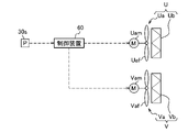
- FIG. 5 is a configuration diagram relating to control of the fan filter unit U on the air supply side and the fan filter unit V on the return air side.
- the air supply side fan filter unit U (first unit) includes an air supply fan Ua (first fan) and a filter Ub.
- the air supply fan Ua is a blower that supplies air to the clean room Rs (see FIG. 4), and includes a fan body Uaf and a fan motor Uam.
- a fan filter unit V (second unit) on the return air side includes a return air fan Va (second fan) and a filter Vb.
- the return air fan Va is a blower for returning air from the clean room Rs (see FIG. 4), and includes a fan main body Vaf and a fan motor Vam.
- a pressure sensor 30s shown in FIG. 5 is a sensor for detecting the room pressure of the clean room Rs (see FIG. 4), and is provided in the clean room Rs.
- the control device 60 (control unit) is a device that controls the supply air fan Ua and the return air fan Va.
- the input side of the control device 60 is connected to the pressure sensor 30s via wiring, while the output side is connected to the supply air fan Ua and the return air fan Va via wiring.
- the control device 60 includes electronic circuits such as a CPU (Central Processing Unit), ROM (Read Only Memory), RAM (Random Access Memory), and various interfaces. Then, the program stored in the ROM is read out and developed in the RAM, and the CPU executes various processes.
- the control device 60 may be configured to include a PLC (Programmable Logic Controller: not shown).
- FIG. 5 shows an example in which the supply air fan Ua and the return air fan Va are connected to one control device 60.
- a controller (not shown) may be provided separately.
- one control device may control supply air fans and return air fans of a plurality of clean rooms.
- the control device 60 drives the supply air fan Ua at a constant speed and controls the return air fan Va based on the detection value of the pressure sensor 30s. do.
- driving the air supply fan Ua at a "constant speed” means that the rotational speed of the air supply fan Ua is kept constant regardless of the detection value of the pressure sensor 30s.
- the controller 60 controls the rotational speed of the air supply fan Ua (that is, the air volume ). Thereby, the cleanliness of the clean room Rs can be maintained at a predetermined level. It should be noted that the degree of “constant” in the "constant speed” need not be strictly “constant” as long as it is effective.
- control device 60 controls the return air fan Va based on the detection value of the pressure sensor 30s so that the room pressure of the clean room Rs (see FIG. 4) reaches a predetermined target pressure (set pressure). For example, when the room pressure of the clean room Rs exceeds the target pressure, the controller 60 increases the rotational speed of the return air fan Va to a predetermined value. This increases the flow rate of air flowing out from the clean room Rs (see FIG. 4) to the duct shaft DS7 (see FIG. 4). On the other hand, the air supply fan Ua is driven at a constant speed as described above. As a result, the room pressure temporarily increased in the clean room Rs is returned to the target pressure.
- the controller 60 reduces the rotation speed of the return air fan Va by a predetermined value.
- the control device 60 changes the rotation speed of the return air fan 3a based on the detection value of the pressure sensor 30s, thereby maintaining the room pressure of the clean room Rs at a predetermined target pressure.
- the clean room Rs is used as a positive pressure room, it is often preferable to set the supply air fan Ua at a constant speed and the return air fan Va at a variable speed based on the room pressure, as described above.
- FIG. 6 is a characteristic diagram showing the relationship between the rotation speed of the return air fan and the air volume.
- the horizontal axis of FIG. 6 is the rotation speed of the return air fan Va (see FIG. 5), and the vertical axis is the air volume of the return air fan Va.
- the higher the rotation speed of the return air fan Va the greater the air volume.
- a DC motor for example, is used as the fan motor Vam (see FIG. 5) of the return air fan Va, the rotation speed and the air volume have a linear relationship (proportional relationship).
- the supply air fan Ua (see FIG. 5) also has the same characteristics as in FIG.
- the return air fan Va (see FIG. 5) is preset with a rotational speed lower limit value N1 shown in FIG. 6 and a corresponding air volume lower limit value Q1.
- an upper limit value N2 of the rotation speed of the return air fan Va and an upper limit value Q2 of the corresponding air volume are also set in advance.
- the lower limit value Q1 of the air volume of the return air fan Va its specific numerical example is 50 [m 3 /h], which is the air volume when adjusting the air volume with a conventional damper (not shown). is about one third of the lower limit of (about 150 [m 3 /h]).
- the return air fan Va has a linear relationship between the rotation speed and the air volume characteristic, so the control device 60 can finely adjust the air volume of the return air fan Va around the lower limit value Q2. Therefore, the room pressure can be adjusted with high accuracy and the power consumption of the air conditioning system S (see FIG. 4) can be greatly reduced compared to the case where the air volume is adjusted by a damper (not shown).
- the controller 60 controls, for example, the air supply fan Wa (see FIG. 4) based on the detected value of the pressure sensor 30t (see FIG. 4). , the return air fan Za (see FIG. 4) is driven at a constant speed.
- the air supply fan Wa also has a linear rotation speed-airflow characteristic (see FIG. 6)
- fine adjustment of the rotation speed of the air supply fan Wa is performed near the lower limit value Q1 (see FIG. 6) of the airflow. Cheap. Therefore, the room pressure of the clean room Rt can be maintained with high accuracy while reducing the power consumption of the air conditioning system S (see FIG. 4).
- the air supply fan It is often better to make the return air fan Za constant speed while Wa is variable speed based on the room pressure.
- the clean room Rs shown in FIG. 4 has been used as a positive pressure room, but at some point, it may be desired to change the purpose and use this clean room Rs as a negative pressure room.
- the controller 60 controls the supply air fan Ua, which has been driven at a constant speed, based on the detection value of the pressure sensor 30s, and controls the return air fan Va, which has been driven at a variable speed. Switch to drive at a constant speed.
- the other clean room Rt shown in FIG. 4 was used as a negative pressure room, but from a certain point in time, it may be desired to change the purpose and use this clean room Rt as a positive pressure room.
- the control device 60 drives the supply air fan Wa, which has been driven at a variable speed, at a constant speed, and drives the return air fan Za, which has been driven at a constant speed, to the detection value of the pressure sensor 30t. switch to control based on
- control device 60 controls one of the supply air fan Ua (first fan) and the return air fan Va (second fan) based on the detection value of the pressure sensor 30s, and controls the other one. Control at constant speed. Further, the control device 60 is configured to be able to switch between the supply air fan Ua and the return air fan Va, which are controlled based on the detection value of the pressure sensor 30s, and which are controlled at a constant speed. there is In other words, the room pressure of the clean room Rs can be switched from one of positive pressure and negative pressure to the other.
- the above-described "switching" may be performed by a user's operation via input means (not shown).
- the control device 60 may temporarily stop the supply air fan Ua and the return air fan Va and then drive them again. . Alternatively, the control device 60 may switch the control method of each fan while continuing to drive the supply air fan Ua and the return air fan Va.
- the one that is controlled based on the detection value of the pressure sensor 30s (see FIG. 4) and the constant It is configured to be switchable between fast control and high speed control. Therefore, one clean room Rs can be selectively used as a positive pressure room or a negative pressure room, so that the user-friendly air conditioning system S can be provided.
- the work load and cost can be greatly reduced, so that it can contribute to society.
- the configuration of the air conditioning system S is simplified. can.
- the construction period for installing the air conditioning system S can be shortened, and the cost required for installation can be reduced.
- the damper opening-air volume characteristic Due to non-linearity and other factors, response delays and overshoots tend to occur in clean room pressure regulation.
- the room pressure of the clean room Rs (see FIG. 4) is adjusted by the return air fan Va or the supply air fan Ua, so the above-described pressure loss and response delay may occur. rare.
- the rotation speed-air volume characteristics of the return air fan Va and the supply air fan Ua are linear (see FIG. 6), the room pressure of the clean room Rs can be maintained with high accuracy. The same can be said for other clean rooms.
- the second embodiment differs from the first embodiment in that no chamber is provided in the space above the ceiling of the clean room.
- the second embodiment differs from the first embodiment in that two clean rooms Rs and Rt (see FIG. 7) are provided in a relatively large large room Ro (see FIG. 7).
- the configuration and control of the fan filter units U, W on the supply air side and the fan filter units V, Z on the return air side are the same as in the first embodiment (see FIGS. 4 and 5).
- the controller 60 can switch the clean rooms Rs and Rt from one of the positive pressure room and the negative pressure room to the other. Therefore, the portions different from the first embodiment will be described, and the description of the overlapping portions will be omitted.
- FIG. 7 is an explanatory diagram of the air conditioning system SA according to the second embodiment.
- two clean rooms Rs and Rt are provided in the large room Ro.
- a filter unit F4 is provided on the ceiling of the large room Ro.
- the filter unit F4 collects dust from the air flowing through the duct D4. HEPA or ULPA, for example, is used as such a filter unit F4.
- the air that has passed through the filter unit F4 is led to the space of the large room Ro.
- a damper B4 is provided near the filter unit F4 in the duct D4. Then, for example, the damper B4 is set to a predetermined degree of opening during the trial operation of the air conditioning system SA, and is maintained at the predetermined degree of opening during subsequent air conditioning operation.
- the gaps Ka and Kb shown in FIG. 7 are ventilation paths through which air flows out from the large room Ro. Then, the air is guided to an air handling unit (not shown) sequentially through the gaps Ka, Kb and the duct D5. The air whose temperature etc. have been adjusted by this air handling unit (not shown) is returned to the large room Ro via another duct D4.
- a fan filter unit U (first unit) on the air supply side is provided on the ceiling of the clean room Rs.
- a fan filter unit V (second unit) on the return air side is provided on the side wall of the clean room Rs.
- the air led to the clean room Rs via the supply air fan Ua is returned to the space of the large room Ro via the return air fan Va and the duct shaft DS7 in sequence. The same applies to the other clean room Rt.
- the control device 60 selects which of the supply air fan Ua (first fan) and the return air fan Va (second fan) is controlled based on the detection value of the pressure sensor 30s and which is controlled at a constant speed. It is configured to be switchable between what is done and what is done. This allows the clean room Rs to be selectively used as a positive pressure room or a negative pressure room. Note that the room pressure adjustment of the clean rooms Rs and Rt is the same as in the first embodiment, so description thereof will be omitted.
- the clean rooms Rs and Rt can be selectively used as positive pressure chambers or negative pressure chambers.
- a good air conditioning system SA can be provided.
- the work load and cost can be greatly reduced compared to the case of separately providing a clean room with a positive pressure chamber or a negative pressure chamber.
- the air volume of the fan controlled at a constant speed may be set by the control device 60, or may be set based on the user's operation via input means (not shown).
- the controller 60 sets the air volume of the air supply fan Ua to increase as the target pressure of the clean room Rs increases.
- the control device 60 sets the air volume of the return air fan Va to be smaller as the target pressure of the clean room Rs is higher.
- the control device 60 drives the supply air fan Ua at a constant speed, while the return air fan Va is operated according to the room pressure.
- the present invention is not limited to this. That is, depending on the usage conditions, when the clean room Rs is used as a positive pressure room, it may be better to drive the return air fan Va at a constant speed while driving the supply air fan Ua at a variable speed based on the room pressure.
- the controller 60 drives the supply air fan Ua at a variable speed based on the room pressure, while the return air fan Va is driven at a constant speed.
- the speed is assumed to be high has been described, the present invention is not limited to this. That is, depending on the conditions of use, when the clean room Rs is used as a negative pressure room, it may be better to drive the supply air fan Ua at a constant speed and make the return air fan Va variable in speed based on the room pressure.
- a return air fan (not shown) for exhausting and returning air from the clean room Rs (see FIG. 4) may be provided. good too.
- the return air fan (second fan) performs exhaust and return air from the clean room Rs
- the suction side of the supply air fan (first fan) and the suction side of the return air fan (second fan) Each side communicates with the space (common space) of the large room Ro.
- part of the clean air in the clean room Rs can be returned to the space in the large room Ro while the rest of the air can be exhausted.
- the one that is controlled based on the detection value of the pressure sensor 30s and the one that is controlled at a constant speed. may be switchable. This allows the clean room Rs to be selectively used as a positive pressure room or a negative pressure room.
- an exhaust fan (not shown) for exhausting air from the clean room Rs may be provided.
- the air supply fan (first fan) and the exhaust fan (second fan) the one that is controlled based on the detection value of the pressure sensor 30s and the one that is controlled at a constant speed are It may be switchable. This allows the clean room Rs to be selectively used as a positive pressure room or a negative pressure room.
- the present invention is not limited to this. That is, the embodiments can be applied to various other fields such as manufacturing of industrial products, food industry, manufacturing of pharmaceuticals, and the like.
- each embodiment is described in detail in order to explain the present invention in an easy-to-understand manner, and is not necessarily limited to those having all the described configurations. Moreover, it is possible to add, delete, or replace a part of the configuration of the embodiment with another configuration. Further, the mechanisms and configurations described above show those considered necessary for explanation, and do not necessarily show all the mechanisms and configurations on the product.
Landscapes
- Engineering & Computer Science (AREA)
- Chemical & Material Sciences (AREA)
- Combustion & Propulsion (AREA)
- Mechanical Engineering (AREA)
- General Engineering & Computer Science (AREA)
- Physics & Mathematics (AREA)
- Fluid Mechanics (AREA)
- Ventilation (AREA)
- Central Air Conditioning (AREA)
- Air Conditioning Control Device (AREA)
Priority Applications (7)
| Application Number | Priority Date | Filing Date | Title |
|---|---|---|---|
| US18/562,476 US20240247817A1 (en) | 2021-06-04 | 2021-06-04 | Air Conditioning System |
| CA3219696A CA3219696C (en) | 2021-06-04 | Air conditioning system | |
| PCT/JP2021/021407 WO2022254705A1 (ja) | 2021-06-04 | 2021-06-04 | 空調システム |
| JP2023525323A JP7649850B2 (ja) | 2021-06-04 | 2021-06-04 | 空調システム |
| TW113135073A TWI908335B (zh) | 2021-06-04 | 2022-04-28 | 空調系統 |
| TW114125948A TW202542459A (zh) | 2021-06-04 | 2022-04-28 | 空調系統 |
| TW111116129A TWI893301B (zh) | 2021-06-04 | 2022-04-28 | 空調系統 |
Applications Claiming Priority (1)
| Application Number | Priority Date | Filing Date | Title |
|---|---|---|---|
| PCT/JP2021/021407 WO2022254705A1 (ja) | 2021-06-04 | 2021-06-04 | 空調システム |
Publications (1)
| Publication Number | Publication Date |
|---|---|
| WO2022254705A1 true WO2022254705A1 (ja) | 2022-12-08 |
Family
ID=84323001
Family Applications (1)
| Application Number | Title | Priority Date | Filing Date |
|---|---|---|---|
| PCT/JP2021/021407 Ceased WO2022254705A1 (ja) | 2021-06-04 | 2021-06-04 | 空調システム |
Country Status (4)
| Country | Link |
|---|---|
| US (1) | US20240247817A1 (https=) |
| JP (1) | JP7649850B2 (https=) |
| TW (3) | TWI893301B (https=) |
| WO (1) | WO2022254705A1 (https=) |
Cited By (4)
| Publication number | Priority date | Publication date | Assignee | Title |
|---|---|---|---|---|
| WO2024166344A1 (ja) * | 2023-02-10 | 2024-08-15 | 日立グローバルライフソリューションズ株式会社 | クリーンルーム施設 |
| WO2025062587A1 (ja) * | 2023-09-21 | 2025-03-27 | 日立グローバルライフソリューションズ株式会社 | クリーンルーム施設 |
| WO2025154283A1 (ja) * | 2024-01-19 | 2025-07-24 | 日立グローバルライフソリューションズ株式会社 | クリーンルーム施設 |
| EP4610178A1 (de) * | 2024-02-29 | 2025-09-03 | Rotzinger PharmaPack GmbH | Automatisierte produktionseinrichtung und produktionslinie |
Citations (7)
| Publication number | Priority date | Publication date | Assignee | Title |
|---|---|---|---|---|
| JPH07145958A (ja) * | 1993-11-26 | 1995-06-06 | Matsushita Seiko Co Ltd | 空調用吹出し装置 |
| JPH08327106A (ja) * | 1995-05-31 | 1996-12-13 | Taikisha Ltd | クリーンルーム設備 |
| JP2000337675A (ja) * | 1999-05-25 | 2000-12-08 | Takasago Thermal Eng Co Ltd | 低露点のクリーンルーム装置 |
| JP2003083578A (ja) * | 2001-09-11 | 2003-03-19 | Hitachi Ltd | クリーンルーム |
| JP2005114317A (ja) * | 2003-10-10 | 2005-04-28 | Taikisha Ltd | 陰陽圧切換式換気設備 |
| JP2010107064A (ja) * | 2008-10-28 | 2010-05-13 | Taikisha Ltd | 室圧制御システム |
| JP2017048940A (ja) * | 2015-08-31 | 2017-03-09 | 株式会社日立製作所 | クリーンルーム用空調システム |
Family Cites Families (14)
| Publication number | Priority date | Publication date | Assignee | Title |
|---|---|---|---|---|
| JPS61291848A (ja) * | 1985-06-19 | 1986-12-22 | Hitachi Ltd | クリ−ンル−ム |
| JPH0560356A (ja) * | 1991-09-03 | 1993-03-09 | Hitachi Plant Eng & Constr Co Ltd | クリーンルーム |
| US5350336A (en) * | 1993-04-23 | 1994-09-27 | Industrial Technology Research Institute | Building and method for manufacture of integrated semiconductor circuit devices |
| JPH1096332A (ja) * | 1996-09-20 | 1998-04-14 | Mitsubishi Electric Corp | クリーンルーム |
| TWM340427U (en) * | 2008-04-16 | 2008-09-11 | Powertech Technology Inc | Cleanroom system |
| TWM396937U (en) * | 2010-04-30 | 2011-01-21 | Taiwan Mika Engineering Consultants Co Ltd | The dry cooling coil (FFU+ Dry coil) for cleanroom. |
| JP2014070748A (ja) | 2012-09-27 | 2014-04-21 | Dainippon Printing Co Ltd | クリーンルームの区画方法、クリーンルーム |
| JP6505551B2 (ja) | 2015-08-31 | 2019-04-24 | 株式会社日立製作所 | クリーンルーム用排気ユニット |
| JP6770357B2 (ja) | 2016-07-11 | 2020-10-14 | 株式会社日立プラントサービス | クリーンルーム用空調システム |
| CN110307603A (zh) | 2019-07-22 | 2019-10-08 | 伍刚 | 一种用于洁净室的集成式空调净化系统 |
| CA3150088C (en) | 2019-12-04 | 2023-10-10 | Mitsuru SEKIZAWA | Air conditioning system |
| JP6810301B1 (ja) | 2020-04-21 | 2021-01-06 | 日立グローバルライフソリューションズ株式会社 | クリーンブース |
| JP7491773B2 (ja) | 2020-08-19 | 2024-05-28 | 株式会社日立プラントサービス | 給排気システム及びクリーンルームシステム |
| CN111829103A (zh) | 2020-08-19 | 2020-10-27 | 江苏博创翰林光电高科技有限公司 | 分布式节能型恒温洁净室 |
-
2021
- 2021-06-04 JP JP2023525323A patent/JP7649850B2/ja active Active
- 2021-06-04 WO PCT/JP2021/021407 patent/WO2022254705A1/ja not_active Ceased
- 2021-06-04 US US18/562,476 patent/US20240247817A1/en active Pending
-
2022
- 2022-04-28 TW TW111116129A patent/TWI893301B/zh active
- 2022-04-28 TW TW114125948A patent/TW202542459A/zh unknown
- 2022-04-28 TW TW113135073A patent/TWI908335B/zh active
Patent Citations (7)
| Publication number | Priority date | Publication date | Assignee | Title |
|---|---|---|---|---|
| JPH07145958A (ja) * | 1993-11-26 | 1995-06-06 | Matsushita Seiko Co Ltd | 空調用吹出し装置 |
| JPH08327106A (ja) * | 1995-05-31 | 1996-12-13 | Taikisha Ltd | クリーンルーム設備 |
| JP2000337675A (ja) * | 1999-05-25 | 2000-12-08 | Takasago Thermal Eng Co Ltd | 低露点のクリーンルーム装置 |
| JP2003083578A (ja) * | 2001-09-11 | 2003-03-19 | Hitachi Ltd | クリーンルーム |
| JP2005114317A (ja) * | 2003-10-10 | 2005-04-28 | Taikisha Ltd | 陰陽圧切換式換気設備 |
| JP2010107064A (ja) * | 2008-10-28 | 2010-05-13 | Taikisha Ltd | 室圧制御システム |
| JP2017048940A (ja) * | 2015-08-31 | 2017-03-09 | 株式会社日立製作所 | クリーンルーム用空調システム |
Cited By (7)
| Publication number | Priority date | Publication date | Assignee | Title |
|---|---|---|---|---|
| WO2024166344A1 (ja) * | 2023-02-10 | 2024-08-15 | 日立グローバルライフソリューションズ株式会社 | クリーンルーム施設 |
| JPWO2024166344A1 (https=) * | 2023-02-10 | 2024-08-15 | ||
| WO2025062587A1 (ja) * | 2023-09-21 | 2025-03-27 | 日立グローバルライフソリューションズ株式会社 | クリーンルーム施設 |
| WO2025154283A1 (ja) * | 2024-01-19 | 2025-07-24 | 日立グローバルライフソリューションズ株式会社 | クリーンルーム施設 |
| JPWO2025154283A1 (https=) * | 2024-01-19 | 2025-07-24 | ||
| JP7825739B2 (ja) | 2024-01-19 | 2026-03-06 | 日立グローバルライフソリューションズ株式会社 | クリーンルーム施設 |
| EP4610178A1 (de) * | 2024-02-29 | 2025-09-03 | Rotzinger PharmaPack GmbH | Automatisierte produktionseinrichtung und produktionslinie |
Also Published As
| Publication number | Publication date |
|---|---|
| US20240247817A1 (en) | 2024-07-25 |
| JP7649850B2 (ja) | 2025-03-21 |
| TWI908335B (zh) | 2025-12-11 |
| CA3219696A1 (en) | 2022-12-08 |
| TW202542459A (zh) | 2025-11-01 |
| TWI893301B (zh) | 2025-08-11 |
| TW202500927A (zh) | 2025-01-01 |
| TW202248575A (zh) | 2022-12-16 |
| JPWO2022254705A1 (https=) | 2022-12-08 |
Similar Documents
| Publication | Publication Date | Title |
|---|---|---|
| JP7649905B2 (ja) | 空調システム及びクリーンルーム施設 | |
| WO2022254705A1 (ja) | 空調システム | |
| AU2020259881B2 (en) | Fan unit, fan unit system, and air treatment system | |
| JP6505551B2 (ja) | クリーンルーム用排気ユニット | |
| JP5490485B2 (ja) | 大型空間室の置換換気設備 | |
| CN203240682U (zh) | 高洁净与高精度实验室 | |
| JP2012202558A (ja) | クリーンルーム空調システム | |
| WO2018180607A1 (ja) | 送風装置およびそれを用いた室内空気搬送システム | |
| JP2014070748A (ja) | クリーンルームの区画方法、クリーンルーム | |
| CA3219696C (en) | Air conditioning system | |
| JP7046642B2 (ja) | クリーンルーム及びクリーンルームの排気量調整方法 | |
| JPS5995327A (ja) | クリ−ンル−ムの空気調和装置 | |
| JP4712853B2 (ja) | 室圧制御システム | |
| JP5785633B2 (ja) | 給気装置 | |
| HK40068920A (en) | Air conditioning system | |
| JP2025174569A (ja) | 工場の空調設備、及び工場の空調設備の制御方法 | |
| Handy et al. | Two approaches to effective ventilation system design for the biomedical device and pharmaceutical industries | |
| WO2024166344A1 (ja) | クリーンルーム施設 | |
| JP2022025268A (ja) | 空調ユニット | |
| JPS6071845A (ja) | 空調防塵室の局所排気装置 | |
| JP2022157580A (ja) | 室圧制御システム | |
| JP2020070955A (ja) | クリーンルームシステム | |
| JP2021008998A (ja) | 空調機、および空調設備 |
Legal Events
| Date | Code | Title | Description |
|---|---|---|---|
| 121 | Ep: the epo has been informed by wipo that ep was designated in this application |
Ref document number: 21944199 Country of ref document: EP Kind code of ref document: A1 |
|
| WWE | Wipo information: entry into national phase |
Ref document number: 2023525323 Country of ref document: JP |
|
| WWE | Wipo information: entry into national phase |
Ref document number: 18562476 Country of ref document: US Ref document number: 3219696 Country of ref document: CA |
|
| NENP | Non-entry into the national phase |
Ref country code: DE |
|
| 122 | Ep: pct application non-entry in european phase |
Ref document number: 21944199 Country of ref document: EP Kind code of ref document: A1 |