WO2024166344A1 - クリーンルーム施設 - Google Patents
クリーンルーム施設 Download PDFInfo
- Publication number
- WO2024166344A1 WO2024166344A1 PCT/JP2023/004512 JP2023004512W WO2024166344A1 WO 2024166344 A1 WO2024166344 A1 WO 2024166344A1 JP 2023004512 W JP2023004512 W JP 2023004512W WO 2024166344 A1 WO2024166344 A1 WO 2024166344A1
- Authority
- WO
- WIPO (PCT)
- Prior art keywords
- room
- air
- clean
- chamber
- duct
- Prior art date
- Legal status (The legal status is an assumption and is not a legal conclusion. Google has not performed a legal analysis and makes no representation as to the accuracy of the status listed.)
- Ceased
Links
Images


Classifications
-
- A—HUMAN NECESSITIES
- A61—MEDICAL OR VETERINARY SCIENCE; HYGIENE
- A61L—METHODS OR APPARATUS FOR STERILISING MATERIALS OR OBJECTS IN GENERAL; DISINFECTION, STERILISATION OR DEODORISATION OF AIR; CHEMICAL ASPECTS OF BANDAGES, DRESSINGS, ABSORBENT PADS OR SURGICAL ARTICLES; MATERIALS FOR BANDAGES, DRESSINGS, ABSORBENT PADS OR SURGICAL ARTICLES
- A61L2/00—Disinfection or sterilisation of materials or objects, in general; Accessories therefor
- A61L2/16—Disinfection or sterilisation of materials or objects, in general; Accessories therefor using chemical substances
- A61L2/20—Gaseous substances, e.g. vapours
- A61L2/208—Hydrogen peroxide
-
- F—MECHANICAL ENGINEERING; LIGHTING; HEATING; WEAPONS; BLASTING
- F24—HEATING; RANGES; VENTILATING
- F24F—AIR-CONDITIONING; AIR-HUMIDIFICATION; VENTILATION; USE OF AIR CURRENTS FOR SCREENING
- F24F3/00—Air-conditioning systems in which conditioned primary air is supplied from one or more central stations to distributing units in the rooms or spaces where it may receive secondary treatment; Apparatus specially designed for such systems
- F24F3/12—Air-conditioning systems in which conditioned primary air is supplied from one or more central stations to distributing units in the rooms or spaces where it may receive secondary treatment; Apparatus specially designed for such systems characterised by the treatment of the air otherwise than by heating and cooling
- F24F3/16—Air-conditioning systems in which conditioned primary air is supplied from one or more central stations to distributing units in the rooms or spaces where it may receive secondary treatment; Apparatus specially designed for such systems characterised by the treatment of the air otherwise than by heating and cooling by purification, e.g. by filtering; by sterilisation; by ozonisation
- F24F3/167—Clean rooms, i.e. enclosed spaces in which a uniform flow of filtered air is distributed
-
- F—MECHANICAL ENGINEERING; LIGHTING; HEATING; WEAPONS; BLASTING
- F24—HEATING; RANGES; VENTILATING
- F24F—AIR-CONDITIONING; AIR-HUMIDIFICATION; VENTILATION; USE OF AIR CURRENTS FOR SCREENING
- F24F7/00—Ventilation
- F24F7/04—Ventilation with ducting systems, e.g. by double walls; with natural circulation
- F24F7/06—Ventilation with ducting systems, e.g. by double walls; with natural circulation with forced air circulation, e.g. by fan positioning of a ventilator in or against a conduit
-
- A—HUMAN NECESSITIES
- A61—MEDICAL OR VETERINARY SCIENCE; HYGIENE
- A61L—METHODS OR APPARATUS FOR STERILISING MATERIALS OR OBJECTS IN GENERAL; DISINFECTION, STERILISATION OR DEODORISATION OF AIR; CHEMICAL ASPECTS OF BANDAGES, DRESSINGS, ABSORBENT PADS OR SURGICAL ARTICLES; MATERIALS FOR BANDAGES, DRESSINGS, ABSORBENT PADS OR SURGICAL ARTICLES
- A61L2103/00—Materials or objects being the target of disinfection or sterilisation
- A61L2103/75—Room floors or walls
-
- A—HUMAN NECESSITIES
- A61—MEDICAL OR VETERINARY SCIENCE; HYGIENE
- A61L—METHODS OR APPARATUS FOR STERILISING MATERIALS OR OBJECTS IN GENERAL; DISINFECTION, STERILISATION OR DEODORISATION OF AIR; CHEMICAL ASPECTS OF BANDAGES, DRESSINGS, ABSORBENT PADS OR SURGICAL ARTICLES; MATERIALS FOR BANDAGES, DRESSINGS, ABSORBENT PADS OR SURGICAL ARTICLES
- A61L2202/00—Aspects relating to methods or apparatus for disinfecting or sterilising materials or objects
- A61L2202/10—Apparatus features
- A61L2202/11—Apparatus for generating biocidal substances, e.g. vaporisers, UV lamps
-
- A—HUMAN NECESSITIES
- A61—MEDICAL OR VETERINARY SCIENCE; HYGIENE
- A61L—METHODS OR APPARATUS FOR STERILISING MATERIALS OR OBJECTS IN GENERAL; DISINFECTION, STERILISATION OR DEODORISATION OF AIR; CHEMICAL ASPECTS OF BANDAGES, DRESSINGS, ABSORBENT PADS OR SURGICAL ARTICLES; MATERIALS FOR BANDAGES, DRESSINGS, ABSORBENT PADS OR SURGICAL ARTICLES
- A61L2202/00—Aspects relating to methods or apparatus for disinfecting or sterilising materials or objects
- A61L2202/10—Apparatus features
- A61L2202/15—Biocide distribution means, e.g. nozzles, pumps, manifolds, fans, baffles, sprayers
-
- F—MECHANICAL ENGINEERING; LIGHTING; HEATING; WEAPONS; BLASTING
- F24—HEATING; RANGES; VENTILATING
- F24F—AIR-CONDITIONING; AIR-HUMIDIFICATION; VENTILATION; USE OF AIR CURRENTS FOR SCREENING
- F24F2221/00—Details or features not otherwise provided for
- F24F2221/22—Cleaning ducts or apparatus
Definitions
- the present invention relates to clean room facilities.
- Patent Document 1 describes such clean rooms as follows: "Of the first fan and the second fan, it is possible to switch between one that is controlled based on the detection value of the pressure sensor and one that is controlled at a constant speed.”
- Patent Document 1 makes it possible to switch a given clean room from one of a positive pressure room and a negative pressure room to the other, but there is room for improvement in terms of air conditioning in the clean room.
- the present invention aims to provide a clean room facility that properly conditions the air in the clean room.
- the clean room facility of the present invention comprises a plurality of clean rooms provided inside a specified room, a first air handling unit that adjusts the temperature of air supplied to the specified rooms, a chamber provided as a single common space above the ceiling of the plurality of clean rooms and into which air is guided from the specified rooms, an air supply fan provided in each of the plurality of clean rooms and that supplies air from the chamber to the clean room, and a duct shaft provided on the outside of a side wall of at least one of the clean rooms, the duct shafts including one that does not communicate with the chambers, and air is guided from the clean rooms to the duct shaft that does not communicate with the chambers and exhausted via the duct shaft.
- the present invention provides a clean room facility that properly conditions the air in the clean room.
- FIG. 2 is an explanatory diagram showing the layout of each room in the clean room facility according to the first embodiment.
- 1 is a schematic cross-sectional view of a clean room facility according to a first embodiment.
- FIG. FIG. 2 is an explanatory diagram showing an example of a process for sterilizing a working room and an antechamber in the clean room facility according to the first embodiment.
- FIG. 11 is an explanatory diagram showing another example of a process for sterilizing a working chamber or an antechamber in the clean room facility according to the first embodiment.
- FIG. 2 is a schematic cross-sectional view of a clean room facility according to a first modified example of the first embodiment.
- FIG. 11 is a schematic cross-sectional view of a clean room facility according to a second modified example of the first embodiment.
- FIG. 11 is a schematic cross-sectional view of a clean room facility according to a second embodiment.
- FIG. 1 is a schematic cross-sectional view of a clean room facility according to a comparative
- FIG. 1 is an explanatory diagram showing the layout of each room of a clean room facility 100 according to the first embodiment.
- the clean room facility 100 is a facility that adjusts the temperature, room pressure, cleanliness, etc. of multiple clean rooms such as antechambers R2 and R4 and work rooms R3 and R5.
- Such clean room facility 100 is used, for example, for cell culture processing and the manufacture of sterile preparations (vaccines, injections, eye drops, etc.).
- the clean room facility 100 includes a large room R1 (a specified room), as well as antechambers R2 and R4 (clean rooms) and work rooms R3 and R5 (clean rooms).
- Large room R1 is a relatively large room where predetermined pre-processing, analysis, etc. are carried out. Although not shown, control panels for equipment used in workrooms R3 and R5, monitoring devices, and utility devices may be provided in large room R1. Below, we will explain the case where large room R1 is a clean room, but large room R1 may also be a normal room.
- a normal room is, for example, a room where the cleanliness level is not controlled, unlike a clean room.
- doors 21-23 are provided at predetermined locations in large room R1 (three locations in the example in Figure 1) that are opened and closed when people enter and exit and when equipment is brought in and out.
- air outlets H1 and H2 are provided in the ceiling of large room R1, from which air whose temperature has been adjusted by air handling unit 30 (first air handling unit: see Figure 2) is blown out.
- Ducts D1 and D2 are provided at predetermined locations (two corners in FIG. 1) of the large room R1.
- Duct D1 is provided with an intake port H3 (second intake port) through which air is drawn from the large room R1 toward the air handling unit 30 (first air handling unit: see FIG. 2).
- the other duct D2 is provided with an intake port H4.
- a fan F1 is provided at the intake port H3 of the duct D1.
- the fan F1 is a blower that sends air from the large room R1 through the duct D1 to the air handling unit 30 (see FIG. 2).
- a fan F2 is provided at the other duct D2.
- the fans F1 and F2 are not essential, and if the fans F1 and F2 are not provided, for example, the duct D3 may be connected to a wall near the fan F1 to replace the duct D1, or the configuration may simply not include the fan F1.
- the anteroom R2 is used, for example, as an airlock to prevent sample contamination.
- the anteroom R2 may also be used for undressing and dressing and for specified pre-processing.
- a door 24 allows people to enter and exit between the anteroom R2 and the large room R1.
- the cleanliness of the anteroom R2 may be higher than that of the large room R1, or may be equal to that of the large room R1. In other words, the cleanliness of the anteroom R2 is higher than that of the large room R1.
- Working room R3 is a clean room where sample preparation and the like are carried out. Examples of such “samples” include, but are not limited to, cells and sterile preparations. Since sample preparation and the like are carried out in working room R3, the cleanliness of working room R3 is higher than that of antechamber R2 and large room R1. If large room R1 is a clean room, the cleanliness of working room R3 is equal to or higher than that of antechamber R2 and large room R1. In addition, people can enter and exit between antechamber R2 and working room R3 via door 25.
- the room pressure of each clean room may be set to be lower than that of the large room R1 and the work room R3, for example. This prevents dust from entering the work room R3 from the large room R1 via the front room R2 when people come and go by opening and closing the doors 24, 25. It also prevents the sample (aerosol) from flowing out from the work room R3 to the large room R1 via the front room R2.
- the room pressures of the large room R1 and the work room R3 may be equal to each other, or one may be higher than the other.
- the front room R2 functions as an airlock. The same applies to the room pressures of the other front room R4 and the work room R5.
- the front room R2 is adjacent to another front room R4 via a wall W1.
- the work room R3 is adjacent to another work room R5 via a wall W1.
- the front rooms R2 and R4 are separated by a wall W1
- the work rooms R3 and R5 are also separated by a wall W1.
- the clean room facility 100 also includes duct shafts DS1, DS2, DS3, and DS4 shown in FIG. 1.
- Duct shaft DS1 is a flow path that guides air from the work room R3 to the large room R1, and extends vertically in a cylindrical shape (see also FIG. 2).
- This duct shaft DS1 is provided in the gap between the work room R3 (a specified clean room) and the large room R1 (a specified room).
- duct shaft DS1 is provided in one corner of work room R3.
- duct shaft DS1 is provided on the outside of the side wall of work room R3.
- duct shaft DS1 may be formed by fitting a cylindrical duct (not shown) into the gap between the work chamber R3 and the large room R1. The same applies to the other duct shafts DS2, DS3, and DS4. As shown in FIG. 1, a fan filter unit 11 is installed in the duct shaft DS1 to exhaust air from the work chamber R3 to the large room R1.
- the other duct shaft DS2 is a flow path that guides air from the front room R2 and the work room R3 to the large room R1, and extends in a cylindrical shape in the vertical direction (see also FIG. 2).
- the duct shaft DS2 is provided in the gap between the front room R2 and the work room R3 (i.e., between the clean rooms).
- the duct shaft DS2 is provided in the gap between the work room R3 (a specified clean room) and the large room R1 (a specified room).
- the duct shaft DS2 is provided on the outside of the side wall of the front room R2 and on the outside of the side wall of the work room R3.
- the duct shaft DS2 is provided with a fan filter unit 14 for exhausting air from the front room R2 to the large room R1.
- the front room R4, work room R5, and duct shafts DS3 and DS4 shown in Figure 1 are arranged generally symmetrically in a plan view with respect to the front room R2, work room R3, and duct shafts DS1 and DS2, with the wall W1 as the base, so a description thereof will be omitted.
- the layout and number of clean rooms in Figure 1 are merely examples, and are not limited to this, and may be changed, for example, by rotating the layout by 90 degrees.
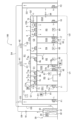
- FIG. 2 is a schematic cross-sectional view of the clean room facility 100. Note that Figure 2 is generally a cross-sectional view taken along line II-II in Figure 1, but in order to clearly show the air flow, the air handling unit 30 as well as the ducts D1 and D2 (see also Figure 1) of the large room R1 are also shown in Figure 2.
- ducts D1 and D2 are air guides through which air exhausted from large room R1 flows, and extend in the vertical direction.
- the air flowing from large room R1 through ducts D1 and D3 in sequence and the air flowing from large room R1 through ducts D2 and D4 in sequence join together, and the joined air is led to the suction side of the air handling unit 30 via duct D5.
- the clean room facility 100 includes an air handling unit 30 (first air handling unit), chambers C1 and C2, a temperature sensor 51, and pressure sensors 61-64.
- the clean room facility 100 also includes dampers 71 and 72 (first dampers), other dampers 81-84 (second dampers), fan filter units 1-8 on the air supply side, and fan filter units 11-18 on the air exhaust side.
- the air handling unit 30 is a device that adjusts the temperature, humidity, etc. of the air supplied to the large room R1 (a specified room). As shown in FIG. 2, the air handling unit 30 includes a filter 31, a cooling coil 32, a fan 33, and an inverter 34.
- the filter 31 collects dust from the air that flows from the large room R1 toward the cooling coil 32 through a duct D5 or the like.
- the cooling coil 32 is a heat exchanger that exchanges heat between the air that has passed through the filter 31 and the refrigerant that flows through a heat transfer tube (not shown). It is also possible to provide the heat exchanger with a humidifying function to adjust the humidity of the air supplied to the large room R1.
- the fan 33 is a blower that sends the air that has been heat exchanged by the cooling coil 32 into the large room R1 through the duct D6.
- the inverter 34 drives the motor (not shown) of the fan 33 in a specified manner.
- the blowing side of the fan 33 and the air outlets H1 and H2 on the ceiling of the large room R1 are connected via a duct D6.
- a filter 41 is installed in the air outlet H1 to collect dust from the air (similar to the other air outlet H2). Note that if the large room R1 is used as a normal room rather than a clean room, there is no particular need to install the filters 41 and 42.
- the air cooled by the air handling unit 30 flows through duct D6 and is then blown out into the large room R1 through the air outlets H1 and H2.
- a damper 10 is installed in the duct D6.
- the damper 10 is set to a predetermined opening during the test run of the air handling unit 30, for example, and is maintained at the above-mentioned predetermined opening during the subsequent air conditioning operation.
- the temperature sensor 51 is a sensor that detects the temperature of the large room R1, and is installed at a specified location in the large room R1. The detected value of the temperature sensor 51 is used to control the air handling unit 30. Although not shown, a humidity sensor may be provided in addition to the temperature sensor 51 so that the temperature and humidity of the large room R1 can be adjusted by the air handling unit 30.
- the pressure sensor 61 is a sensor that detects the chamber pressure in the work chamber R3 and is installed in the work chamber R3. The detection value of the pressure sensor 61 is used to control the fan filter units 11-13 on the exhaust side of the work chamber R3. Note that the fan filter unit 13 (see Figure 1) at the rear of the duct shaft DS2 and the fan filter unit 16 (see Figure 1) at the rear of another duct shaft DS3 are not shown in Figure 2.
- the pressure sensor 62 is a sensor that detects the chamber pressure in the front chamber R2 and is installed in the front chamber R2. The detection value of the pressure sensor 62 is used to control the fan filter unit 14 on the exhaust side of the front chamber R2. The same is true for the remaining pressure sensor 63 in the front chamber R4 and the pressure sensor 64 in the working chamber R5.
- Chamber C1 shown in Figure 2 is the space above the ceiling of the work room R3 and the anteroom R2.
- chamber C1 is provided as a common space above the ceiling of multiple clean rooms such as the work room R3 and the anteroom R2.
- Another chamber C2 shown in Figure 2 is the space above the ceiling of the anteroom R4 and the work room R5.
- These two chambers C1 and C2 are adjacent to each other via a wall W1.
- This wall W1 not only separates chambers C1 and C2, but also, as mentioned above, separates the anterooms R2 and R4, and also separates the work rooms R3 and R5 (see Figure 1).
- the grill G1 shown in FIG. 2 is a member that guides air from the large room R1 to the damper 71 while preventing the damper 71 from being exposed to the large room R1.
- the grill G1 may be configured with multiple blades (louvers) arranged in parallel at a specified interval, or may be configured in a mesh-like manner.
- the gaps between the blades of the grill G1 function as a "first suction port" through which air is sucked in from the large room R1 (a specified room) toward the chamber C1. This "first suction port" is provided near the chamber C1.
- grill G1 is shown on the left side of the page, and another grill G2 is shown on the right side of the page, but grills G1 and G2 may be provided on the front side where doors 24 and 26 (see FIG. 1) are provided.
- Damper 71 switches between communication and blocking between large room R1 (a specified room) and chamber C1.
- This damper 71 is provided on the air inlet side of chamber C1, in a position facing grill G1.
- damper 72 is provided on the air inlet side of another chamber C2.
- These dampers 71 and 72 should preferably be non-leak dampers (airtight dampers) that are highly airtight when closed. In this way, when sterilization is being performed in working rooms R3 and R5 or anterooms R2 and R4, the dampers 71 and 72 can be closed to prevent sterilization gas from flowing into large room R1.
- the dampers 71 and 72 are maintained in the open state during normal use of the clean room facility 100.
- each of the chambers C1 and C2 is connected to the large room R1.
- the air from the large room R1 is led to the chamber C1 through the grill G1 and damper 71 (open state) in sequence.
- the air from the large room R1 is led to the other chamber C2 through the grill G2 and damper 72 (open state) in sequence.
- Chamber C1 is composed of the ceilings of the work chamber R3 and front chamber R2, an upper plate C1a, and a side plate C1b.
- the upper plate C1a is higher than the ceilings of the work chamber R3 and front chamber R2 and is approximately parallel to these ceilings.
- the side plate C1b is a plate that connects the edges of the ceilings of the work chamber R3 and front chamber R2 to the edges of the upper plate C1a and extends in the vertical direction. The same is true for the other chamber C2.
- a structure including multiple clean rooms with a common chamber will be referred to as a "clean unit.”
- a structure including a work chamber R3 and antechamber R2 with a common chamber C1 above the ceiling will be referred to as a first clean unit U1.
- a structure including antechamber R4 and work chamber R5 with a common chamber C2 above the ceiling will be referred to as a second clean unit U2.
- the first clean unit U1 and the second clean unit U2 are adjacent to each other via a wall W1, but they may also be configured to be separated from each other.
- Fan filter units 1-3 shown in Figure 2 are devices that supply air from chamber C1 to work room R3, and are embedded in the ceiling of work room R3.
- Fan filter unit 1 includes supply air fan 1a and filter 1b.
- Supply air fan 1a is a blower that supplies air from chamber C1 to work room R3 (clean room).
- Filter 1b collects dust from the air flowing from supply air fan 1a to work chamber R3 and is provided on the outlet side of supply air fan 1a.
- a HEPA High Efficiency Particulate Air Filter
- ULPA Ultra Low Penetration Air Filter
- the remaining fan filter units 2 and 3 used to supply air to work chamber R3 are also configured in the same way.
- the fan filter unit 4 is a device that supplies air from the chamber C1 to the front room R2.
- the fan filter unit 4 is equipped with an air supply fan 4a and a filter 4b, and is embedded in the ceiling of the front room R2. In this way, an "air supply fan” is provided in each of the multiple “clean rooms.”
- the other fan filter units 5 to 8 on the air supply side are also configured in the same way.
- the fan filter unit 11 shown in FIG. 2 is a device that exhausts air from the work chamber R3, and includes an exhaust fan 11a and a filter 11b.
- the exhaust fan 11a is a blower that exhausts air from the work chamber R3, and is installed in the duct shaft DS1. That is, an opening is provided in a predetermined location on the duct shaft DS1 facing the work chamber R3, and the fan filter unit 11 is fitted into this opening.
- the filter 11b collects dust from the air flowing from the work chamber R3 toward the exhaust fan 11a, and is provided on the suction side of the exhaust fan 11a.
- the other fan filter units 12 to 18 on the exhaust side are configured in the same way.
- the upper end of the duct shaft DS1 is closed and does not communicate with the chamber C1.
- the duct shaft DS1 also communicates with the work room R3 via the exhaust fan 11a. Air is guided from the work room R3 (clean room) to the duct shaft DS1 that does not communicate with the chamber C1, and is exhausted through the duct shaft DS1. In other words, air is exhausted from the work room R3 (clean room) that communicates with the duct shaft DS1 through the duct shaft DS1 that does not communicate with the chamber C1.
- the exhaust destination when exhausting air from the work room R3 through the duct shaft DS1 is the large room R1 (a specified room). The same can be said for exhausting air through the other duct shafts DS2, DS3, and DS4.
- the damper 81 (second damper) shown in FIG. 2 switches between communication and blocking between the duct shaft DS1 and the large room R1 (a specific room), and is provided on the side of the duct shaft DS1 facing the large room R1.
- the damper 82 (second damper) shown in FIG. 2 switches between communication and blocking between the duct shaft DS2 and the large room R1.
- Fan filter unit 12 shown in FIG. 2 and fan filter unit 13 shown in FIG. 1 are devices that exhaust air from work chamber R3 and are installed in duct shaft DS2.
- Another fan filter unit 14 is a device that exhausts air from front chamber R2 and is also installed in duct shaft DS2.
- the duct shaft DS2 is provided in the gap between the work chamber R3 and the front room R2.
- the upper end of this duct shaft DS2 is also closed, so it does not communicate with the chamber C1.
- the duct shaft DS2 also communicates with the work chamber R3 via the exhaust fan 12a, etc., and also communicates with the front room R2 via another exhaust fan 14a.
- the air in the work chamber R3 and the front room R2 is exhausted to the large room R1 through the duct shaft DS2 and the damper 82 (open state) in sequence (see also Figure 1).
- the downward arrow near the damper 82 in Figure 2 indicates the flow of air toward the large room R1.
- the fan filter units 1-8 on the intake side and the fan filter units 11-18 on the exhaust side are controlled by a control device (not shown). Note that each of the fan filter units 1-8 and 11-18 may have a built-in control device, or multiple fan filter units may be connected to a single control device via wiring.
- the rotation speed of exhaust fans 11a, 12a, 13a is controlled, for example, to maintain the room pressure in work chamber R3 at a predetermined set pressure (target pressure).
- the rotation speed of supply fans 1a, 2a, 3a may be constant or may be adjusted appropriately based on the room pressure in work chamber R3.
- the clean room facility 100 is generally symmetrical with respect to wall W1, a description of the configuration related to air conditioning in antechamber R4 and work chamber R5 will be omitted.
- FIG. 8 is a schematic cross-sectional view of a clean room facility 200 according to a comparative example.
- the comparative example of Fig. 8 differs from the first embodiment (see Fig. 2) in that no damper is provided, and that duct shafts DS1 and DS2 communicate with chamber C1, while duct shafts DS3 and DS4 communicate with another chamber C2.
- the comparative example of Fig. 8 also differs from the first embodiment in that duct shafts DS1 and DS4 do not communicate with large room R1.
- the comparative example of Fig. 8 also differs from the first embodiment (see Fig. 2) in that duct shaft DS2 communicates with large room R1 through opening A1, and the remaining duct shaft DS3 communicates with large room R1 through another opening A2.
- the duct shafts DS1 and DS2 of the clean unit U1 include those that do not communicate with the chamber C1.
- neither of the duct shafts DS1 and DS2 communicate with the chamber C1.
- the same can be said for the duct shafts DS3 and DS4 of the other clean unit U2.
- the air handling unit 30, the fan filter units 1-8 on the air supply side, and the fan filter units 11-18 on the air exhaust side are driven in a predetermined manner.
- the damper 71 on the air inlet side of the chamber C1 is open, and the large room R1 and the chamber C1 communicate with each other through the damper 71 (similar to the other damper 72).
- the damper 81 provided on the duct shaft DS1 is open, and the duct shaft DS1 and the large room R1 communicate with each other through the damper 81 (similar to the other dampers 82-84).
- part of the air led from the large room R1 to the chamber C1 via the damper 71 is led to the work room R3, and part of the air in the work room R3 is exhausted to the large room R1 via the duct shaft DS1 and damper 81 in sequence.
- the work room R3 can be conditioned with high efficiency. The same can be said for the air conditioning of the other antechambers R2, R4 and the work room R5.
- FIG. 3 is an explanatory diagram showing an example of a process during sterilization of the working chamber R3 and the anterior chamber R2.
- the sterilization gas generator 91 shown in Fig. 3 is a device that generates a specified sterilization gas (hydrogen peroxide gas, etc.).
- the sterilization gas generator 91 is arranged in the working room R3, and when the sterilization gas generator 91 is driven with all the doors closed, the sterilization gas generator 91 generates a sterilization gas.
- chambers C1 and C2 are separated by wall W1, for example, sterilization gas generated by sterilization gas generator 91 does not flow from working chamber R3 through chamber C1 into the adjacent chamber C2. Therefore, even during sterilization of working chamber R3 or antechamber R2, there is no problem if the fan filter units 15-18 on the air supply side and the fan filter units 15-18 on the exhaust side of the other antechamber R4 and working chamber R5 continue to be driven, and there is also no problem if dampers 72, 83, and 84 remain open.
- the fan filter units 1-4 on the air supply side in the chamber C1 are kept stopped, and the fan filter units 11-14 that exhaust air from the working chamber R3 and the front chamber R2 are also kept stopped.
- the damper 71 (first damper) and dampers 81, 82 (second dampers) are kept closed.
- the sterilizing gas filling the working chamber R3 flows into the chamber C1 through the stopped air supply side fan filter units 1-3, and further flows into the front chamber R2 through the remaining air supply side fan filter unit 4.
- the sterilizing gas filling the working chamber R3 also flows into the duct shaft DS1 through the stopped exhaust side fan filter unit 11, and also flows into the duct shaft DS2 through the fan filter unit 12, etc.
- the sterilizing gas flows into the front chamber R2 through the exhaust side fan filter unit 14 from the duct shaft DS2.
- the sterilizing gas generator 91 in one clean room (working chamber R3 in the example of Figure 3), the working chamber R3, front chamber R2, and duct shafts DS1 and DS2, which share the common chamber C1, can be sterilized all at once.
- the damper 71 on the air inlet side of chamber C1 is closed, blocking the communication between large room R1 and chamber C1. This prevents sterilized gas from leaking from chamber C1 to large room R1.
- the damper 81 provided on duct shaft DS1 is also closed, blocking the communication between large room R1 and duct shaft DS1. This prevents sterilized gas from leaking into large room R1 through duct shaft DS1. Similarly, sterilized gas can be prevented from leaking into large room R1 through the other duct shaft DS2.
- a sterilization gas generator 91 may be placed in the anterior chamber R2. Also, a sterilization gas generator 91 may be placed in each of the working chamber R3 and the anterior chamber R2. In short, when sterilizing multiple clean rooms, it is advisable to place a sterilization gas generator 91 in at least one of the multiple clean rooms.
- the air handling unit 30 and fans F1, F2 running even during sterilization of the work room R3 or the front room R2. This allows the large room R1 to be maintained at a specified temperature even during sterilization.
- the fan filter units 5-8, 15-18 can be kept running to air-condition the front room R4 and work room R5, which have chambers C2 different from the chamber C1 in the ceiling above the work room R3, even during sterilization of the work room R3, etc. Therefore, work such as sample preparation can continue to be carried out in the front room R4 and work room R5.
- FIG. 4 is an explanatory diagram showing another example of the process during sterilization of the working chamber R3 and the anterior chamber R2.
- a sterilization gas generator 92 may be disposed outside the working chamber R3 (inside the large room R1 or outside the large room R1), and sterilization gas may be supplied from this sterilization gas generator 92 to the working chamber R3 via a hose 93. That is, when multiple clean rooms such as the working chamber R3 and the anteroom R2 are to be sterilized, sterilization gas may be supplied from the sterilization gas generator 92 to at least one of the multiple clean rooms from the outside via the hose 93. With this configuration, the same effects as in Fig. 3 can be achieved.
- an exhaust hose (not shown) for exhausting air from the working chamber R3 may be connected to the sterilization gas generator 92.
- air that has been rendered harmless by catalytic gas air in which the concentration of sterilization gas is equal to or lower than a predetermined value
- the exhaust hose (not shown).
- sterilization gas or the like may be circulated via a predetermined pipe or duct.
- a decomposition device (not shown) equipped with a specified catalytic filter (not shown) that renders the sterilization gas harmless may be provided separately.
- a catalytic filter may be provided downstream of the dampers 81 and 82 on the exhaust side to reduce the concentration of the sterilization gas by the catalyst.
- the working chamber R3 can be appropriately conditioned, and the efficiency of air conditioning when cooling the working chamber R3 is improved. The same can be said about the air conditioning of the other anterior chambers R2, R4 and the working chamber R5.
- the anterooms R2 and R4 and the workrooms R3 and R5 are provided inside the large room R1, it becomes easier to, for example, add a new clean room inside the large room R1 or change the layout.
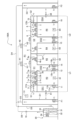
- FIG. 5 is a schematic cross-sectional view of a clean room facility 100A according to a first modified example of the first embodiment.
- the clean room facility 100A shown in Fig. 5 differs from the first embodiment (see Fig. 2) in that the duct shaft DS2 communicates with the chamber C1 and the duct shaft DS3 communicates with another chamber C2.
- the clean room facility 100A shown in Fig. 5 also differs from the first embodiment in that no dampers are provided in the duct shafts DS2 and DS3, and neither of the duct shafts DS2 and DS3 communicates with the large room R1. Other points are the same as those in the first embodiment, so a description of the overlapping parts will be omitted.
- the duct shaft DS2 is connected to the chamber C1, but the other duct shafts DS1 are not connected to the chamber C1. Therefore, at least in the flow path via the duct shaft DS1, the occurrence of a closed-loop air flow can be suppressed. Similarly, in the flow path via the duct shaft DS4 of the second clean unit U2, a closed-loop air flow hardly occurs. Therefore, although the air conditioning efficiency is slightly inferior to the first embodiment, the working room R3 and the like can be appropriately air-conditioned.
- the air that flows into the duct shaft DS2 from the work chamber R3 is returned (returned) to the chamber C1 via the duct shaft DS2. Therefore, the highly clean air supplied to the chamber C1 can be reused.
- duct shaft DS1 may be connected to chamber C1
- another duct shaft DS4 may be connected to chamber C2
- the remaining duct shafts DS2, DS3 may not be connected to chambers C1, C2.
- air conditioning of the work room R3, etc. can be performed appropriately.
- the configuration includes at least one duct shaft that is not connected to chambers C1, C2 among the multiple duct shafts DS1, DS2, DS3, DS4.
- no dampers are installed in the duct shafts DS2 and DS3 that communicate with the chamber C1, but this is not limited to the above. That is, a damper (not shown) may be installed in each of the duct shafts DS2 and DS3. In this case, for example, a portion of the air that flows into the duct shaft DS2 from the work room R3 is returned to the chamber C1 via the duct shaft DS2, and the remaining air is led to the large room R1 via an open damper (not shown). Even with this configuration, clean air can be reused while properly conditioning each clean room such as the work room R3.
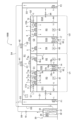
- FIG. 6 is a schematic cross-sectional view of a clean room facility 100B according to a second modified example of the first embodiment. 6 differs from the first embodiment in that the duct shaft DS1 is not provided with an exhaust fan filter unit, but instead has an opening A3 (the same applies to the other duct shafts DS4). Other points are similar to those in the first embodiment, so descriptions of overlapping parts will be omitted.
- an opening A3 is provided on the work chamber R3 side of the duct shaft DS1. Air is exhausted from the work chamber R3 through the opening A3, duct shaft DS1, and damper 81 (open) in that order to the large room R1. The same applies to exhaust through duct shaft DS4.
- the positions of the openings A3 and A4 are not limited to the example in FIG. 6, and some or all of the exhaust fans 11a to 18a (see FIG. 2) described in the first embodiment may be omitted, and openings may be provided in the omitted locations. Filters may also be installed in each of these openings as appropriate.
- the second embodiment differs from the first embodiment in that a first clean unit U3 (see FIG. 7) having a predetermined chamber C3 and a second clean unit U4 (see FIG. 7) having another chamber C4 are provided separately from each other.
- the second embodiment also differs from the first embodiment in that an air handling unit 9 (see FIG. 7) that individually conditions the air for the second clean unit U4 is provided.
- the rest of the second embodiment is similar to the first embodiment. Therefore, only the parts that differ from the first embodiment will be described, and the explanation of the overlapping parts will be omitted.
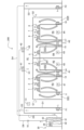
- FIG. 7 is a schematic cross-sectional view of a clean room facility 100C according to the second embodiment.
- the clean room facility 100C includes a first clean unit U3, a second clean unit U4, and an air handling unit 9 (second air handling unit).
- the first clean unit U3 includes a work room R3 and an antechamber R2 as a plurality of clean rooms that share a chamber C3 in common.
- the second clean unit U4 includes a work room R5 and an antechamber R4 as a plurality of clean rooms that share a chamber C4 in common.
- the first clean unit U3 and the second clean unit U4 are provided inside a large room R1 (a specified room).
- R1 a specified room
- the configuration of the first clean unit U3 is similar to that of the first clean unit U1 (see FIG. 2) described in the first embodiment, so a description thereof will be omitted.
- the second clean unit U4 has a configuration generally similar to that of the first clean unit U3.
- the second clean unit U4 differs from the first clean unit U3 in that a grill is not provided upstream of the damper 72, and instead a wall W3 is provided.
- the downstream end of a duct D7, through which air cooled by the air handling unit 9 flows, is inserted into this wall W3. It is also possible to configure the downstream end of the duct D7 to be directly connected to the damper 72.
- the second clean unit U4 has a larger air conditioning load than the first clean unit U3. For example, if the amount of heat generated by equipment (not shown) installed in the workroom R5, etc. is large, or if the set temperature (target temperature) of the workroom R5, etc. is lower than that of the workroom R3, etc. of the first clean unit U3, the air conditioning load of the second clean unit U4 will often be relatively large. Therefore, in the second embodiment, the air in the large room R1 is additionally cooled by the air handling unit 9 before being supplied to the second clean unit U4.
- the air handling unit 9 is an air conditioner that draws in air from the large room R1 (a specified room), adjusts the temperature, and supplies the temperature-adjusted air to the chamber C4 of the second clean unit U4.
- the air handling unit 9 is equipped with a filter 9a, a cooling coil 9b, a fan 9c, and an inverter 9d.
- the configuration of the air handling unit 9 shown in FIG. 7 is similar to that of another air handling unit 30 for cooling the air in the large room R1, so a description thereof will be omitted.
- the air drawn into the air handling unit 9 from the large room R1 is cooled to a specified degree, and the cooled air is led to the chamber C4 via the duct D7 and the damper 72 (open state) in sequence.
- a damper 10a is installed in duct D7.
- Damper 10a is set to a predetermined opening degree, for example, during a trial run of air handling unit 9, and is maintained at the predetermined opening degree during subsequent air conditioning operation.
- the opening degree of damper 10a may be adjusted as appropriate based on the air conditioning load of front room R4 and work room R5.
- the working room R3 and the anteroom R2 are maintained at a predetermined set temperature by directly supplying the air from the large room R1 (i.e., the air cooled by the air handling unit 30) to the first clean unit U3. Therefore, for the first clean unit U3, there is no particular need to provide an air handling unit for individual air conditioning.
- the air handling unit 9 is configured to suck in the air of the large room R1, but this is not limited thereto.
- the air handling unit 9 may be configured to selectively suck in the air of the large room R1 and the air of the work room R5 based on the temperature information of the large room R1 and the temperature information of the work room R5.
- the air handling unit 9 when the air handling unit 9 performs cooling operation, when the temperature of the work room R5 is lower than the temperature of the large room R1, the air handling unit 9 is configured to suck in the air of the work room R5. Also, when the temperature of the large room R1 is lower than the temperature of the work room R5, the air handling unit 9 is configured to suck in the air of the large room R1. This reduces the air conditioning load of the air handling unit 9, thereby achieving energy conservation.
- the target for the air handling unit 9 to suck in the air may be either the large room R1 or the work room R5.
- air further cooled by the air handling unit 9 is supplied to the chamber C4 of the second clean unit U4. Therefore, even if the air conditioning load of the second clean unit U4 is larger than that of the first clean unit U3, air conditioning suitable for the usage environment of the second clean unit U4 can be performed individually.
- the large room R1 and the first clean unit U3 can also be appropriately air-conditioned by a separate air handling unit 30.
- a predetermined gap is provided between the ceiling of the large room R1 and the upper plate C1a of the chamber C1, and between the ceiling of the large room R1 and the upper plate C2a of the chamber C2, but this is not limited to the above.
- the upper plates C1a, C2a may be integrated into the ceiling of the large room R1.
- the side walls of the first clean unit U1, etc. may be integrated into part of the side walls of the large room R1.
- the exhaust destination from the clean room such as the working room R3 is the large room R1
- the exhaust destination from the clean room such as the working room R3 may be a space outside the clean room facility 100.
- the number of clean room units is two, but the present invention is not limited to this. That is, the large room R1 (predetermined room) may be configured to have at least one clean room unit.
- the dampers 81 to 84 are provided to correspond to the duct shafts DS1, DS2, DS3, and DS4, but the present invention is not limited to this.
- the dampers 81 to 84 may be omitted, and a specific duct shaft may communicate with the large room R1 via an exhaust port (second exhaust port: not shown).
- an operator may cover the exhaust port so that sterilization gas does not flow into the large room R1 via the exhaust port.
- the sterilization gas generators 91, 92 (see Figs. 3 and 4) that generate sterilization gas are provided, but the present invention is not limited to this.
- a device having an aeration function using a catalyst or the like in addition to the functions of dehumidification and predetermined gas generation may be provided.
- the sterilization gas generators 91, 92 may also have these functions.
- the air in the large room R1 (see FIG. 2) is guided to the air handling unit 30, and the air cooled by the air handling unit 30 is returned to the large room R1, but this is not limited to the above.
- an air handling unit (not shown) outdoors in the clean room facility may take in outside air, and the air cooled by this air handling unit may be guided to the large room R1.
- the exhaust destination from a specified clean room may be outdoors.
- the layout of the clean room facility 100 etc. described in each embodiment is one example, but other layouts may also be configured as follows. That is, the clean room facility may be provided with duct shafts that are provided in the gaps between the clean rooms among the multiple clean rooms and/or in the gaps between a specific clean room and the large room R1 (specific room). Also, one or more duct shafts may be provided on the outside of the side wall of at least one clean room. In such a configuration, the one or more duct shafts include one that is not connected to the chamber. This allows air to be exhausted from the specific clean room to the large room R1 etc. via the duct shaft that is not connected to the chamber, thereby preventing air from circulating in a closed loop.
- the duct shafts DS1, DS2, DS3, and DS4 may be arranged in a straight line along a specific side wall facing the large room R1. This allows workers to open the maintenance covers (not shown) of the duct shafts DS1, DS2, DS3, and DS4 to expose the fan filter units 11-18, and work sequentially along the side wall, making maintenance work easier.
- a porous plate or grating may be provided at the upper end (downstream end of the air flow) of the duct shaft DS2.
- a porous plate or grating may be provided at the upper end (downstream end of the air flow) of the duct shaft DS2.
- Such a configuration is also included in the matter of the duct shaft DS2 being in communication with the chamber C1.
- the air handling unit 9 individually performs air conditioning for the second clean unit U4, but this is not limited to the above. That is, two air handling units 9 (second air handling units) may be installed inside the large room R1 so as to correspond one-to-one to the first clean unit U3 and the second clean unit U4. The air in the large room R1 may then be cooled by each air handling unit 9, and the cooled air may be guided to the chambers C3 and C4. With this configuration, even if the set temperatures of the first clean unit U3 and the second clean unit U4 are different from that of the large room R1, the air handling units 9 can assist in air conditioning.
- a duct shaft may be provided in the gap between the side wall of the large room R1 and a specified clean room.
- a duct shaft may not communicate with the chamber C1, and furthermore, air may be exhausted from the clean room to the outside of the large room R1 via the duct shaft.
- the damper 71 (see FIG. 2) is hidden by the grill G1 when viewed from inside the large room R1, and another damper 72 (see FIG. 2) is hidden by the grill G2, but this is not limiting.
- the grills G1 and G2 may be omitted as appropriate, and the dampers 71 and 72 may be exposed to the large room R1.
- a configuration has been described in which the damper 81 is provided on the large room R1 side of the duct shaft DS1 (the main body of the damper 81 is exposed to the large room R1), but this is not limited to the above.
- the damper 81 may be installed inside the duct shaft DS1. This makes the damper 81 hidden when viewed from inside the large room R1, improving the design. The same applies to the other dampers 82 to 84.
- the air outlets H1, H2 first air outlets: see FIG. 1
- the air handling unit 30 first air handling unit
- the air outlets H1, H2 are provided upstream in the air flow direction relative to the intake ports (first intake ports: gaps in the grills G1, G2) near the chambers C1, C2.
- the conditioned air blown out from the outlets H1, H2 is led directly to the chamber C1 via the intake port, so that cooled air can be sent to the front rooms R2, R4 and the work rooms R3, R5.
- a damper 81 (second damper) or a second exhaust port (not shown) that guides the air exhausted from the duct shaft DS1 (see FIG. 2) to the large room R1 (a specified room) may be provided on the duct shaft DS1.
- an intake port H3 (second intake port: see FIG. 1) that draws in air from the large room R1 toward the air handling unit 30 (first air handling unit) may be provided on the duct D1 (see FIG. 1).
- an intake port H3 (second intake port) is provided downstream of the damper 81 (second damper) or the second exhaust port in the air flow direction.
- the chambers C1 and C2 are described as being separated by a wall W1, but this is not limited thereto.
- the wall W1 may not be provided, and the chambers C1 and C2 may be one common space.
- the clean rooms such as the work chambers R3 and R5 and the anterooms R2 and R4 are described as being used as positive pressure rooms, but depending on the application, the clean rooms may be used as negative pressure rooms.
- the clean room facility 100 and the like are described as being used for cell culture processing and pharmaceutical manufacturing, but this is not limited to this.
- each embodiment can be applied to various fields such as the manufacturing of semiconductors, precision machinery, and liquid crystal panels, the food industry, the cosmetics industry, and experiments using radioactive materials.
Landscapes
- Engineering & Computer Science (AREA)
- Chemical & Material Sciences (AREA)
- General Engineering & Computer Science (AREA)
- Mechanical Engineering (AREA)
- Combustion & Propulsion (AREA)
- Health & Medical Sciences (AREA)
- Animal Behavior & Ethology (AREA)
- General Health & Medical Sciences (AREA)
- Public Health (AREA)
- Veterinary Medicine (AREA)
- Life Sciences & Earth Sciences (AREA)
- Epidemiology (AREA)
- General Chemical & Material Sciences (AREA)
- Chemical Kinetics & Catalysis (AREA)
- Ventilation (AREA)
Abstract
クリーンルームの空調を適切に行うクリーンルーム施設を提供する。クリーンルーム施設(100)は、大部屋(R1)の内部に設けられるクリーンルームである前室(R2)及び作業室(R3)と、大部屋(R1)に供給される空気の温度を調整するエアハンドリングユニット(30)と、前室(R2)及び作業室(R3)の天井裏に1つの共通の空間として設けられ、大部屋(R1)から空気が導かれるチャンバ(C1)と、給気ファン(1a,2a,3a,4a)と、ダクトシャフト(DS1,DS2)と、を備え、ダクトシャフト(DS1,DS2)には、チャンバ(C1)に連通していないものが含まれ、チャンバ(C1)に連通していないダクトシャフト(DS1,DS2)に前室(R2)や作業室(R3)から空気が導かれ、ダクトシャフト(DS1,DS2)を介して排気される。
Description
本発明は、クリーンルーム施設に関する。
再生医療や医薬品の製造等において、空気の清浄度の高いクリーンルームが用いられている。このようなクリーンルームに関して、例えば、特許文献1には、「前記第1ファン及び前記第2ファンのうち、前記圧力センサの検出値に基づいて制御されるものと、一定速で制御されるものと、が切替可能である」ことが記載されている。
特許文献1に記載の技術では、所定のクリーンルームを陽圧室及び陰圧室のうちの一方から他方に切り替えることが可能になるが、クリーンルームの空調の点では改善の余地がある。
そこで、本発明は、クリーンルームの空調を適切に行うクリーンルーム施設を提供することを課題とする。
前記した課題を解決するために、本発明に係るクリーンルーム施設は、所定の部屋の内部に設けられる複数のクリーンルームと、前記所定の部屋に供給される空気の温度を調整する第1エアハンドリングユニットと、複数の前記クリーンルームの天井裏に1つの共通の空間として設けられ、前記所定の部屋から空気が導かれるチャンバと、複数の前記クリーンルームのそれぞれに設けられ、前記チャンバから当該クリーンルームへの給気を行う給気ファンと、少なくとも一つの前記クリーンルームの側壁の外側に設けられるダクトシャフトと、を備え、前記ダクトシャフトには、前記チャンバに連通していないものが含まれ、前記チャンバに連通していない前記ダクトシャフトに前記クリーンルームから空気が導かれ、当該ダクトシャフトを介して排気されることとした。
本発明によれば、クリーンルームの空調を適切に行うクリーンルーム施設を提供できる。
≪第1実施形態≫
<クリーンルーム施設の構成>
図1は、第1実施形態に係るクリーンルーム施設100の各部屋の間取りを示す説明図である。
なお、図1では、空気が流れる向きを矢印で示している。クリーンルーム施設100は、前室R2,R4や作業室R3,R5といった複数のクリーンルームの温度や室圧、清浄度等を調整する施設である。このようなクリーンルーム施設100は、例えば、細胞の培養加工や無菌製剤(ワクチン、注射剤、点眼剤等)の製造に用いられる。図1の例では、クリーンルーム施設100が大部屋R1(所定の部屋)を備える他、前室R2,R4(クリーンルーム)と、作業室R3,R5(クリーンルーム)と、を備えている。
<クリーンルーム施設の構成>
図1は、第1実施形態に係るクリーンルーム施設100の各部屋の間取りを示す説明図である。
なお、図1では、空気が流れる向きを矢印で示している。クリーンルーム施設100は、前室R2,R4や作業室R3,R5といった複数のクリーンルームの温度や室圧、清浄度等を調整する施設である。このようなクリーンルーム施設100は、例えば、細胞の培養加工や無菌製剤(ワクチン、注射剤、点眼剤等)の製造に用いられる。図1の例では、クリーンルーム施設100が大部屋R1(所定の部屋)を備える他、前室R2,R4(クリーンルーム)と、作業室R3,R5(クリーンルーム)と、を備えている。
大部屋R1は、所定の前処理や分析等が行われる比較的広い部屋である。なお、図示はしないが、作業室R3,R5で用いられる機器の操作盤やモニタリング装置やユーティリティ装置が大部屋R1に設けられるようにしてもよい。以下では、大部屋R1がクリーンルームである場合について説明するが、大部屋R1は通常の部屋であってもよい。通常の部屋とは、例えばクリーンルームに対して清浄度が管理されていない部屋のことである。
図1に示すように、大部屋R1の所定箇所(図1の例では3箇所)には、人の出入りや機器の搬入・搬出の際に開閉されるドア21~23が設けられている。また、大部屋R1の天井には、エアハンドリングユニット30(第1エアハンドリングユニット:図2参照)で温度が調整された空気が吹き出される吹出口H1,H2(第1吹出口)が設けられている。
大部屋R1の所定箇所(図1では2箇所の隅部)には、ダクトD1,D2が設けられている。ダクトD1には、大部屋R1からエアハンドリングユニット30(第1エアハンドリングユニット:図2参照)に向かう空気が吸い込まれる吸込口H3(第2吸込口)が設けられている。同様に、他方のダクトD2にも吸込口H4が設けられている。図1に示すように、ダクトD1の吸込口H3には、ファンF1が設置されている。ファンF1は、大部屋R1からダクトD1を介して、エアハンドリングユニット30(図2参照)に空気を送り込む送風機である。同様に、他方のダクトD2にもファンF2が設置されている。なお、ファンF1,F2は必須ではなく、これらのファンF1,F2が設けられない場合は、例えば、ダクトD3をファンF1近傍の壁に接続してダクトD1の代わりにしてもよく、また、単にファンF1が設けられない構成としてもよい。
大部屋R1(所定の部屋)の内部には、複数のクリーンルームとして、前室R2,R4及び作業室R3,R5が設けられている。前室R2は、例えば、試料汚染(コンタミネーション)を抑制するためのエアロックとして用いられる。なお、脱衣・着衣や所定の前処理に前室R2が用いられてもよい。図1の例では、前室R2と大部屋R1との間でドア24を介して、人が出入りできるようになっている。前室R2の清浄度は、大部屋R1の清浄度よりも高くてもよいし、また、大部屋R1の清浄度と同等であってもよい。つまり、前室R2の清浄度は、大部屋R1の清浄度以上になっている。
作業室R3は、試料の調製等が行われるクリーンルームである。このような「試料」として、例えば、細胞や無菌製剤が挙げられるが、これに限定されるものではない。このように作業室R3では試料の調整等が行われるため、作業室R3の清浄度は、前室R2や大部屋R1の清浄度よりも高くなっている。なお、大部屋R1がクリーンルームの場合は、作業室R3の清浄度は、前室R2や大部屋R1の清浄度以上になっている。また、前室R2と作業室R3との間でドア25を介して、人が出入りできるようになっている。
各クリーンルームの室圧については、試料汚染を抑制するために、例えば、大部屋R1や作業室R3の室圧よりも前室R2の室圧の方が低くなるようにしてもよい。これによって、ドア24,25を開閉して人が行き来する過程で、大部屋R1から前室R2を介して作業室R3に塵埃が入り込むことを抑制できる。また、作業室R3から前室R2を介して大部屋R1に試料(エアロゾル)が流出することも抑制できる。なお、大部屋R1と作業室R3の室圧が互いに等しくなるようにしてよいし、また、一方が他方よりも高くなるようにしてもよい。その他、大部屋R1や作業室R3の室圧よりも前室R2の室圧の方が高い場合でも、前室R2がエアロックとして機能する。なお、別の前室R4や作業室R5の室圧についても同様である。
図1の例では、壁W1を介して、前室R2が別の前室R4に隣り合っている。同様に、壁W1を介して、作業室R3が別の作業室R5に隣り合っている。つまり、前室R2,R4が壁W1で仕切られるとともに、作業室R3,R5も壁W1で仕切られている。
クリーンルーム施設100は、前記した各構成の他に、図1に示すダクトシャフトDS1,DS2,DS3,DS4を備えている。ダクトシャフトDS1は、作業室R3から大部屋R1に空気を導く流路であり、上下方向に筒状に延びている(図2も参照)。このダクトシャフトDS1は、作業室R3(所定のクリーンルーム)と大部屋R1(所定の部屋)との間の隙間に設けられている。図1の例では、作業室R3の隅部の一つにダクトシャフトDS1が設けられている。また、別の観点から説明すると、作業室R3の側壁の外側にダクトシャフトDS1が設けられている。
なお、作業室R3の側壁の一部がダクトシャフトDS1の一部を形成するようにしてもよい。また、作業室R3と大部屋R1との間の隙間に筒状のダクト(図示せず)が嵌め込まれることで、ダクトシャフトDS1が形成されるようにしてもよい。なお、他のダクトシャフトDS2,DS3,DS4についても同様である。図1に示すように、ダクトシャフトDS1には、作業室R3から大部屋R1への排気を行うためのファンフィルタユニット11が設置されている。
別のダクトシャフトDS2は、前室R2や作業室R3から大部屋R1に空気を導く流路であり、上下方向に筒状に延びている(図2も参照)。図1に示すように、ダクトシャフトDS2は、前室R2と作業室R3との間(つまり、クリーンルーム同士の間)の隙間に設けられている。また、別の観点では、作業室R3(所定のクリーンルーム)と大部屋R1(所定の部屋)との間の隙間にダクトシャフトDS2が設けられている、ともいえる。また、ダクトシャフトDS2は、前室R2の側壁の外側に設けられるとともに、作業室R3の側壁の外側に設けられている。ダクトシャフトDS2には、作業室R3から大部屋R1への排気を行うためのファンフィルタユニット12,13の他、前室R2から大部屋R1への排気を行うためのファンフィルタユニット14が設置されている。
図1に示す前室R4や作業室R5やダクトシャフトDS3,DS4については、壁W1を基準として、前室R2や作業室R3やダクトシャフトDS1,DS2に対して、平面視で概ね対称の配置になっているから、その説明を省略する。なお、図1の間取りやクリーンルームの数は一例であり、例えば間取りを90°回転させるなど、これに限定されるものではない。
図2は、クリーンルーム施設100の模式的な断面図である。
なお、図2は概ね、図1のII‐II線の断面図になっているが、空気の流れを分かりやすく示すために、大部屋R1のダクトD1,D2(図1も参照)の他、エアハンドリングユニット30も図2に示すようにしている。
なお、図2は概ね、図1のII‐II線の断面図になっているが、空気の流れを分かりやすく示すために、大部屋R1のダクトD1,D2(図1も参照)の他、エアハンドリングユニット30も図2に示すようにしている。
前記したように、ダクトD1,D2は、大部屋R1から排気された空気が通流する風導管であり、上下方向に延びている。そして、大部屋R1からダクトD1,D3を順次に介して通流する空気と、大部屋R1からダクトD2,D4を順次に介して通流する空気と、が合流し、合流した空気がダクトD5を介して、エアハンドリングユニット30の吸込側に導かれるようになっている。
図2に示すように、クリーンルーム施設100は、エアハンドリングユニット30(第1エアハンドリングユニット)と、チャンバC1,C2と、温度センサ51と、圧力センサ61~64と、を備えている。また、クリーンルーム施設100は、前記した構成の他に、ダンパ71,72(第1ダンパ)と、別のダンパ81~84(第2ダンパ)と、給気側のファンフィルタユニット1~8と、排気側のファンフィルタユニット11~18と、を備えている。
エアハンドリングユニット30は、大部屋R1(所定の部屋)に供給される空気の温度や湿度等を調整する装置である。図2に示すように、エアハンドリングユニット30は、フィルタ31と、冷却コイル32と、ファン33と、インバータ34と、を備えている。フィルタ31は、大部屋R1からダクトD5等を介して冷却コイル32に向かう空気から塵埃を捕集するものである。冷却コイル32は、フィルタ31を通過した空気と、伝熱管(図示せず)を通流する冷媒と、の間で熱交換が行われる熱交換器である。なお、熱交換器に加湿機能を設けて、大部屋R1に供給される空気の湿度を調整する場合も考えられる。ファン33は、冷却コイル32で熱交換した空気を、ダクトD6を介して、大部屋R1に送り込む送風機である。インバータ34は、ファン33のモータ(図示せず)を所定に駆動させる。
図2に示すように、ファン33の吹出側と、大部屋R1の天井の吹出口H1,H2とは、ダクトD6を介して接続されている。吹出口H1には、空気から塵埃を捕集するためのフィルタ41が設置されている(他方の吹出口H2も同様)。なお、大部屋R1がクリーンルームではなく通常の部屋として用いられる場合には、フィルタ41,42を設置する必要は特にない。
そして、エアハンドリングユニット30で冷やされた空気がダクトD6を介して通流し、さらに、吹出口H1,H2を介して大部屋R1に吹き出されるようになっている。図1に示すように、ダクトD6には、ダンパ10が設置されている。ダンパ10は、例えば、エアハンドリングユニット30の試運転時に所定開度に設定され、その後の空調運転中は、前記した所定開度で維持される。
温度センサ51は、大部屋R1の温度を検出するセンサであり、大部屋R1の所定箇所に設置されている。温度センサ51の検出値は、エアハンドリングユニット30の制御に用いられる。その他、図示はしないが、温度センサ51の他に湿度センサを設け、エアハンドリングユニット30によって大部屋R1の温度及び湿度が調整されるようにしてもよい。
圧力センサ61は、作業室R3の室圧を検出するセンサであり、作業室R3に設置されている。圧力センサ61の検出値は、作業室R3の排気側のファンフィルタユニット11~13等の制御に用いられる。なお、ダクトシャフトDS2の奥側のファンフィルタユニット13(図1参照)や、別のダクトシャフトDS3の奥側のファンフィルタユニット16(図1参照)については、図2では図示を省略している。
圧力センサ62は、前室R2の室圧を検出するセンサであり、前室R2に設置されている。圧力センサ62の検出値は、前室R2の排気側のファンフィルタユニット14等の制御に用いられる。なお、残りの前室R4の圧力センサ63や作業室R5の圧力センサ64についても同様である。
図2に示すチャンバC1は、作業室R3や前室R2の天井裏の空間である。つまり、作業室R3や前室R2といった複数のクリーンルームの天井裏に1つの共通の空間として、チャンバC1が設けられている。図2に示す別のチャンバC2は、前室R4や作業室R5の天井裏の空間である。これら2つのチャンバC1,C2は、壁W1を介して隣り合っている。この壁W1は、チャンバC1,C2を仕切る他、前記したように、前室R2,R4を仕切り、また、作業室R3,R5も仕切っている(図1参照)。
図2に示すグリルG1は、ダンパ71を大部屋R1に露出させないようにしつつ、大部屋R1の空気をダンパ71に導く部材である。グリルG1は、複数の羽根(ルーバ)が所定の間隔で平行に配置された構成であってもよいし、また、網状の構成であってもよい。グリルG1の羽根の間の隙間(網状の場合には複数の孔)は、大部屋R1(所定の部屋)からチャンバC1に向かう空気が吸い込まれる「第1吸込口」として機能する。この「第1吸込口」は、チャンバC1の付近に設けられている。なお、図2の紙面右側の別のグリルG2についても同様である。
ちなみに、図2では紙面左側にグリルG1を図示し、また、紙面右側に別のグリルG2を図示しているが、ドア24,26(図1参照)が設けられている正面側にグリルG1,G2が設けられていてもよい。
ダンパ71(第1ダンパ)は、大部屋R1(所定の部屋)とチャンバC1との間の連通又は遮断を切り替えるものである。このダンパ71は、チャンバC1の空気入口側において、グリルG1に面する位置に設けられている。同様に、別のチャンバC2の空気入口側にもダンパ72が設けられている。これらのダンパ71,72として、閉状態での気密性が高いノンリークダンパ(気密ダンパ)を用いるようにするとよい。これによって、作業室R3,R5や前室R2,R4の滅菌が行われるとき、ダンパ71,72を閉状態にすることで、滅菌ガスが大部屋R1に流入することを防止できる。
なお、ダンパ71,72は、クリーンルーム施設100の通常使用時には開状態で維持される。つまり、クリーンルーム施設100の通常使用時には、それぞれのチャンバC1,C2が大部屋R1に連通している。そして、大部屋R1の空気がグリルG1及びダンパ71(開状態とする)を順次に介して、チャンバC1に導かれるようになっている。同様に、大部屋R1の空気がグリルG2及びダンパ72(開状態とする)を順次に介して、他方のチャンバC2に導かれる。
チャンバC1は、作業室R3や前室R2の天井と、上板C1aと、側板C1bと、を含んで構成されている。上板C1aは、作業室R3や前室R2の天井よりも高さ位置が高く、この天井に対して略平行になっている。側板C1bは、作業室R3や前室R2の天井の縁部と上板C1aの縁部とを接続する板であり、上下方向に延びている。なお、他方のチャンバC2についても同様である。
以下では、チャンバが共通である複数のクリーンルームを含む構造物を「クリーンユニット」という。図2の例では、天井裏のチャンバC1が共通である作業室R3や前室R2を含む構造体を第1クリーンユニットU1とする。また、天井裏のチャンバC2が共通である前室R4や作業室R5を含む構造体を第2クリーンユニットU2とする。なお、第1クリーンユニットU1と第2クリーンユニットU2とは壁W1を介して隣り合っているが、これらが互いに離れた構成であってもよい。
図2に示すファンフィルタユニット1~3は、チャンバC1から作業室R3への給気を行う機器であり、作業室R3の天井に埋設されている。ファンフィルタユニット1は、給気ファン1aと、フィルタ1bと、を備えている。給気ファン1aは、チャンバC1から作業室R3(クリーンルーム)への給気を行う送風機である。
フィルタ1bは、給気ファン1aから作業室R3に向かう空気から塵埃を捕集するものであり、給気ファン1aの吹出側に設けられている。このようなフィルタ1bとして、例えば、HEPA(High Efficiency Particulate Air Filter)やULPA(Ultra Low Penetration Air Filter)が用いられる。なお、作業室R3への給気に用いられる残りのファンフィルタユニット2,3も同様の構成になっている。
ファンフィルタユニット4は、チャンバC1から前室R2への給気を行う機器である。ファンフィルタユニット4は、給気ファン4aと、フィルタ4bと、を備え、前室R2の天井に埋設されている。このように、複数の「クリーンルーム」のそれぞれに「給気ファン」が設けられている。なお、給気側の他のファンフィルタユニット5~8も同様の構成になっている。
図2に示すファンフィルタユニット11は、作業室R3からの排気を行う機器であり、排気ファン11aと、フィルタ11bと、を備えている。排気ファン11aは、作業室R3からの排気を行う送風機であり、ダクトシャフトDS1に設置されている。つまり、ダクトシャフトDS1において作業室R3に面する所定箇所に開口が設けられ、この開口にファンフィルタユニット11が嵌め込まれている。フィルタ11bは、作業室R3から排気ファン11aに向かう空気から塵埃を捕集するものであり、排気ファン11aの吸込側に設けられている。なお、排気側の他のファンフィルタユニット12~18も同様の構成になっている。
図2に示すように、ダクトシャフトDS1は、その上端が閉塞された状態であり、チャンバC1には連通していない。また、ダクトシャフトDS1は、排気ファン11aを介して、作業室R3に連通している。そして、チャンバC1に連通していないダクトシャフトDS1に作業室R3(クリーンルーム)から空気が導かれ、ダクトシャフトDS1を介して排気されるようになっている。換言すると、チャンバC1に連通していないダクトシャフトDS1を介して、このダクトシャフトDS1に連通している作業室R3(クリーンルーム)から排気される。図2の例では、ダクトシャフトDS1を介して作業室R3から排気される際の排気先が、大部屋R1(所定の部屋)になっている。なお、他のダクトシャフトDS2,DS3,DS4を介した排気についても同様のことがいえる。
図2に示すダンパ81(第2ダンパ)は、ダクトシャフトDS1と大部屋R1(所定の部屋)との間の連通又は遮断を切り替えるものであり、ダクトシャフトDS1において大部屋R1に面する側に設けられている。図2に示すダンパ82(第2ダンパ)は、ダクトシャフトDS2と大部屋R1との間の連通又は遮断を切り替えるものである。なお、他のダンパ82,83,84についても同様である。これらのダンパ81~84として、閉状態での気密性が高いノンリークダンパ(気密ダンパ)を用いるようにするとよい。これによって、例えば、作業室R3,R5や前室R2,R4の滅菌が行われるとき、ダンパ81~84を閉状態にすることで、滅菌ガスが大部屋R1に流入することを防止できる。なお、ダンパ81~84は、クリーンルーム施設100の通常使用時には開状態で維持される。
図2に示すファンフィルタユニット12や、図1に示すファンフィルタユニット13は、作業室R3からの排気を行う機器であり、ダクトシャフトDS2に設置されている。また、別のファンフィルタユニット14は、前室R2からの排気を行う機器であり、ダクトシャフトDS2に設置されている。
ダクトシャフトDS2は、前記したように、作業室R3と前室R2との間の隙間に設けられている。このダクトシャフトDS2も、上端が閉塞されているため、チャンバC1には連通していない。また、ダクトシャフトDS2は、排気ファン12a等を介して作業室R3に連通するとともに、別の排気ファン14aを介して前室R2にも連通している。これらの排気ファン12a~14aが駆動することで、作業室R3や前室R2の空気が、ダクトシャフトDS2及びダンパ82(開状態とする)を順次に介して、大部屋R1に排気されるようになっている(図1も参照)。なお、図2のダンパ82の付近の下向き矢印は、大部屋R1に向かう空気の流れを示している。
給気側のファンフィルタユニット1~8や排気側のファンフィルタユニット11~18は、制御装置(図示せず)によって制御される。なお、ファンフィルタユニット1~8,11~18のそれぞれに制御装置が内蔵されていてもよいし、また、複数のファンフィルタユニットが配線を介して1つの制御装置に接続されるようにしてもよい。
排気ファン11a,12a,13a(図1も参照)の回転速度は、例えば、作業室R3の室圧を所定の設定圧力(目標圧力)で維持するように制御される。給気ファン1a,2a,3aの回転速度については、一定であってもよいし、また、作業室R3の室圧に基づいて適宜に調整されるようにしてもよい。なお、残りの前室R2,R4や作業室R5の室圧制御についても同様である。また、クリーンルーム施設100は、壁W1を基準として概ね対称の構成であるため、前室R4や作業室R5の空調に関わる構成については説明を省略する。
<比較例>
図8は、比較例に係るクリーンルーム施設200の模式的な断面図である。
図8の比較例は、ダンパが設けられておらず、また、ダクトシャフトDS1,DS2がチャンバC1に連通するとともに、ダクトシャフトDS3,DS4が別のチャンバC2に連通している点が、第1実施形態(図2参照)とは異なっている。また、図8の比較例は、ダクトシャフトDS1,DS4が大部屋R1に連通していない点が、第1実施形態とは異なっている。また、図8の比較例は、ダクトシャフトDS2が開口部A1を介して大部屋R1に連通し、また、残りのダクトシャフトDS3が別の開口部A2を介して大部屋R1に連通している点が、第1実施形態(図2参照)とは異なっている。
図8の比較例の構成では、例えば、排気側のファンフィルタユニット11の駆動に伴い、作業室R3からダクトシャフトDS1に流入した空気がチャンバC1に戻される。また、排気側のファンフィルタユニット12~14の駆動に伴い、作業室R3や前室R2からダクトシャフトDS2に流出した空気の一部は開口部A1を介して大部屋R1に排気されるが、残りの空気はダクトシャフトDS2を介してチャンバC1に戻される。
そうすると、図8の白抜き矢印で示すように、例えば、作業室R3で吸熱した空気がダクトシャフトDS1を介してチャンバC1に戻され、さらに、この空気のほとんどが給気側のファンフィルタユニット1~3によって作業室R3に給気される。このような空気の循環(クローズドループ)が生じると、大部屋R1からチャンバC1に導かれた調和空気(エアハンドリングユニット30で冷やされた空気)が作業室R3に給気される際の流れが阻害される。その結果、作業室R3を所定の目標とする温度に維持する際の空調効率の低下を招き、作業室R3が目標とする温度に維持されにくくなる。なお、他の前室R2,R4や作業室R5の空調についても同様のことがいえる。
これに対して、第1実施形態では、クリーンユニットU1のダクトシャフトDS1,DS2には、チャンバC1に連通していないものが含まれている。図2の例では、ダクトシャフトDS1,DS2のいずれもチャンバC1には連通していない。なお、他方のクリーンユニットU2のダクトシャフトDS3,DS4についても同様のことがいえる。これによって、前記したクローズドループの流れが生じることを抑制できる。したがって、作業室R3,R5や前室R2,R4の空調効率が高められる。
次に、クリーンルーム施設100の通常使用時の処理と、滅菌時の処理と、について順に説明する。なお、通常使用時の処理については、主に図2を用いて説明する。
次に、クリーンルーム施設100の通常使用時の処理と、滅菌時の処理と、について順に説明する。なお、通常使用時の処理については、主に図2を用いて説明する。
<通常使用時の処理>
クリーンルーム施設100の通常使用時には、エアハンドリングユニット30の他、給気側のファンフィルタユニット1~8や排気側のファンフィルタユニット11~18が所定に駆動される。また、チャンバC1の空気入口側のダンパ71は開状態であり、大部屋R1とチャンバC1とがダンパ71を介して連通している(他方のダンパ72も同様)。また、ダクトシャフトDS1に設けられたダンパ81は開状態であり、ダクトシャフトDS1と大部屋R1とがダンパ81を介して連通している(他のダンパ82~84も同様)。このように、作業室R3,R5や前室R2,R4といったクリーンルームの空調が行われているとき、ダンパ71,72(第1ダンパ)及びダンパ81~84(第2ダンパ)が開状態で維持される。
クリーンルーム施設100の通常使用時には、エアハンドリングユニット30の他、給気側のファンフィルタユニット1~8や排気側のファンフィルタユニット11~18が所定に駆動される。また、チャンバC1の空気入口側のダンパ71は開状態であり、大部屋R1とチャンバC1とがダンパ71を介して連通している(他方のダンパ72も同様)。また、ダクトシャフトDS1に設けられたダンパ81は開状態であり、ダクトシャフトDS1と大部屋R1とがダンパ81を介して連通している(他のダンパ82~84も同様)。このように、作業室R3,R5や前室R2,R4といったクリーンルームの空調が行われているとき、ダンパ71,72(第1ダンパ)及びダンパ81~84(第2ダンパ)が開状態で維持される。
例えば、大部屋R1からダンパ71を介してチャンバC1に導かれた空気の一部は、作業室R3に導かれ、さらに作業室R3の空気の一部がダクトシャフトDS1及びダンパ81を順次に介して、大部屋R1に排気される。前記したように、ダクトシャフトDS1はチャンバC1に連通していないため、空気のクローズドループの流れが生じることはほとんどない。したがって、作業室R3の空調を高効率で行うことができる。なお、他の前室R2,R4や作業室R5の空調についても同様のことがいえる。
<滅菌時の処理>
例えば、作業室R3で人が作業を行っているときに試料をこぼすといったことが生じる可能性がある。また、清浄な作業環境を維持するために、各クリーンルームの滅菌を定期的に行うことが望ましい。そこで、滅菌時には、図3や図4に示すような処理が適宜に行われる。
例えば、作業室R3で人が作業を行っているときに試料をこぼすといったことが生じる可能性がある。また、清浄な作業環境を維持するために、各クリーンルームの滅菌を定期的に行うことが望ましい。そこで、滅菌時には、図3や図4に示すような処理が適宜に行われる。
図3は、作業室R3や前室R2の滅菌時の処理の例を示す説明図である。
図3に示す滅菌ガス発生装置91は、所定の滅菌ガス(過酸化水素ガス等)を発生させる装置である。例えば、作業室R3に滅菌ガス発生装置91が配置され、各ドアが閉められた状態で滅菌ガス発生装置91が駆動されると、滅菌ガス発生装置91から滅菌ガスが発生するようになっている。
図3に示す滅菌ガス発生装置91は、所定の滅菌ガス(過酸化水素ガス等)を発生させる装置である。例えば、作業室R3に滅菌ガス発生装置91が配置され、各ドアが閉められた状態で滅菌ガス発生装置91が駆動されると、滅菌ガス発生装置91から滅菌ガスが発生するようになっている。
なお、チャンバC1,C2は壁W1で仕切られているため、例えば、滅菌ガス発生装置91で発生した滅菌ガスが、作業室R3からチャンバC1を介して、隣のチャンバC2に入り込むといったことは生じない。したがって、作業室R3や前室R2の滅菌中も、別の前室R4や作業室R5の給気側のファンフィルタユニット15~18や排気側のファンフィルタユニット15~18が駆動され続けても特に支障はなく、また、ダンパ72,83,84が開状態のままであっても特に支障はない。
一方、作業室R3及び前室R2の滅菌中は、チャンバC1における給気側のファンフィルタユニット1~4が停止状態で維持されるとともに、作業室R3や前室R2からの排気を行うファンフィルタユニット11~14も停止状態で維持される。また、滅菌ガスを用いて、作業室R3及び前室R2(複数のクリーンルーム)の滅菌が行われているとき、ダンパ71(第1ダンパ)及びダンパ81,82(第2ダンパ)は閉状態で維持される。
例えば、作業室R3に充満した滅菌ガスは、停止状態の給気側のファンフィルタユニット1~3を介してチャンバC1に流入し、さらに、給気側の残りのファンフィルタユニット4を介して、前室R2にも流入する。また、作業室R3に充満した滅菌ガスは、停止状態の排気側のファンフィルタユニット11を介してダクトシャフトDS1に流入する他、ファンフィルタユニット12等を介してダクトシャフトDS2にも流入する。その他、ダクトシャフトDS2から排気側のファンフィルタユニット14を介して、前室R2に滅菌ガスが流入する。このように、一つのクリーンルーム(図3の例では作業室R3)で滅菌ガス発生装置91を駆動させることで、共通のチャンバC1を有する作業室R3や前室R2やダクトシャフトDS1,DS2の滅菌を一括で行うことができる。
前記したように、チャンバC1の空気入口側のダンパ71は閉状態であるため、大部屋R1とチャンバC1との間がダンパ71で遮断されている。したがって、チャンバC1から大部屋R1に滅菌ガスが漏れ出ることを防止できる。また、ダクトシャフトDS1に設けられたダンパ81も閉状態であるため、大部屋R1とダクトシャフトDS1との間がダンパ81で遮断されている。したがって、ダクトシャフトDS1を介して、大部屋R1に滅菌ガスが漏れ出ることを防止できる。同様に、他のダクトシャフトDS2を介して大部屋R1に滅菌ガスが漏れ出ることも防止できる。
なお、第1クリーンユニットU1の滅菌を行う際、図3の例に代えて、前室R2に滅菌ガス発生装置91が配置されるようにしてもよい。また、作業室R3と前室R2のそれぞれに滅菌ガス発生装置91が配置されるようにしてもよい。要するに、複数のクリーンルームを滅菌する際、複数のクリーンルームのうちの少なくとも一つに滅菌ガス発生装置91が配置されるようにするとよい。
また、作業室R3や前室R2の滅菌中でも、エアハンドリングユニット30やファンF1,F2を駆動させ続けることが可能である。これによって、滅菌中でも大部屋R1を所定温度で維持できる。また、例えば、滅菌ガス発生装置91が作業室R3に配置される場合において、作業室R3の天井裏のチャンバC1とは異なるチャンバC2を有する前室R4や作業室R5の空調については、作業室R3等の滅菌中もファンフィルタユニット5~8,15~18を駆動させ続けることができる。したがって、前室R4や作業室R5で試料の調整等の作業を行い続けることができる。
図4は、作業室R3や前室R2の滅菌時の処理の別の例を示す説明図である。
図4に示すように、作業室R3の外側(大部屋R1の内側、又は、大部屋R1の外側)に滅菌ガス発生装置92を配置し、この滅菌ガス発生装置92からホース93を介して、作業室R3に滅菌ガスを供給するようにしてもよい。すなわち、作業室R3や前室R2といった複数のクリーンルームを滅菌する際、複数のクリーンルームのうちの少なくとも一つに外側からホース93を介して、滅菌ガス発生装置92から滅菌ガスが供給されるようにしてもよい。このような構成でも、図3の場合と同様の効果が奏される。
また、図4に示すホース93の他、作業室R3からの排気を行うための排気ホース(図示せず)が滅菌ガス発生装置92に接続されるようにしてもよい。この場合において、例えば、触媒ガスで無害化された空気(滅菌ガスの濃度が所定値以下の空気)が排気ホース(図示せず)を介して排気されるようにしてもよい。また、ホースに代えて、所定の配管やダクトを介して、滅菌ガス等が循環するようにしてもよい。
その他、滅菌ガスを無害化する所定の触媒フィルタ(図示せず)を備えた分解装置(図示せず)を別途設けるようにしてもよい。また、排気側のダンパ81,82の下流側に触媒フィルタを設け、触媒によって滅菌ガスの濃度を低下させるようにしてもよい。
<効果>
第1実施形態によれば、例えば、ダクトシャフトDS1(図2参照)がチャンバC1に連通していないため、ダクトシャフトDS1及びチャンバC1を介して空気が循環する(クローズドループが生じる)といったことを防止できる。したがって、作業室R3の空調を適切に行うことができる他、作業室R3の冷房を行う際の空調効率が高められる。なお、他の前室R2,R4や作業室R5の空調についても同様のことがいえる。
第1実施形態によれば、例えば、ダクトシャフトDS1(図2参照)がチャンバC1に連通していないため、ダクトシャフトDS1及びチャンバC1を介して空気が循環する(クローズドループが生じる)といったことを防止できる。したがって、作業室R3の空調を適切に行うことができる他、作業室R3の冷房を行う際の空調効率が高められる。なお、他の前室R2,R4や作業室R5の空調についても同様のことがいえる。
また、例えば、作業室R3と大部屋R1との間にダクトシャフトDS1を設けることで、ダクトシャフトDS1にダンパ81を設けることが可能になる。したがって、作業室R3等の滅菌時にダンパ81を閉じた状態にすることで、大部屋R1に滅菌ガスが漏れることを防止できる。また、ダクトシャフトDS1の内部に排気側のファンフィルタユニット11を設置することで、大部屋R1からファンフィルタユニット11が見えないようにすることができる。これによって、クリーンルーム施設100の意匠性が高められる。
また、前室R2,R4や作業室R3,R5が大部屋R1の内部に設けられるため、例えば、大部屋R1の内部で新たなクリーンルームを増設したり、レイアウトを変更したりするといったことが行いやすくなる。
≪第1実施形態の第1の変形例≫
図5は、第1実施形態の第1の変形例に係るクリーンルーム施設100Aの模式的な断面図である。
なお、図5に示すクリーンルーム施設100Aは、ダクトシャフトDS2がチャンバC1に連通し、また、ダクトシャフトDS3が別のチャンバC2に連通している点が、第1実施形態(図2参照)とは異なっている。また、図5に示すクリーンルーム施設100Aは、ダクトシャフトDS2,DS3にダンパが設けられておらず、ダクトシャフトDS2,DS3がいずれも大部屋R1と連通していない点が、第1実施形態とは異なっている。なお、その他の点は第1実施形態と同様の構成であるから、重複する部分については説明を省略する。
図5は、第1実施形態の第1の変形例に係るクリーンルーム施設100Aの模式的な断面図である。
なお、図5に示すクリーンルーム施設100Aは、ダクトシャフトDS2がチャンバC1に連通し、また、ダクトシャフトDS3が別のチャンバC2に連通している点が、第1実施形態(図2参照)とは異なっている。また、図5に示すクリーンルーム施設100Aは、ダクトシャフトDS2,DS3にダンパが設けられておらず、ダクトシャフトDS2,DS3がいずれも大部屋R1と連通していない点が、第1実施形態とは異なっている。なお、その他の点は第1実施形態と同様の構成であるから、重複する部分については説明を省略する。
図5に示すように、例えば、第1クリーンユニットU1において、ダクトシャフトDS2はチャンバC1に連通しているが、他のダクトシャフトDS1はチャンバC1には連通していない。したがって、少なくともダクトシャフトDS1を介した流路では、空気のクローズドループの流れが生じることを抑制できる。同様に、第2クリーンユニットU2のダクトシャフトDS4を介した流路でも、空気のクローズドループの流れはほとんど生じない。したがって、第1実施形態に比べると空調効率が若干劣るものの、作業室R3等の空調を適切に行うことができる。
また、作業室R3からダクトシャフトDS2に流入した空気は、ダクトシャフトDS2を介してチャンバC1に戻される(還気される)。したがって、チャンバC1に供給された清浄度の高い空気を再利用できる。
なお、所定のダクトシャフトとチャンバC1,C2との間の連通・非連通の組合せは、図5の例に限定されない。例えば、ダクトシャフトDS1がチャンバC1に連通し、また、別のダクトシャフトDS4がチャンバC2に連通し、残りのダクトシャフトDS2,DS3はチャンバC1,C2に連通しない構成であってもよい。このような構成でも、作業室R3等の空調を適切に行うことができる。要するに、複数のダクトシャフトDS1,DS2,DS3,DS4のうち、チャンバC1,C2に連通していないダクトシャフトが少なくとも一つ含まれる構成であればよい。
また、図5の例では、チャンバC1に連通しているダクトシャフトDS2,DS3にダンパが設置されない例を示したが、これに限らない。すなわち、ダクトシャフトDS2,DS3にそれぞれダンパ(図示せず)が設置されるようにしてもよい。この場合には、例えば、作業室R3からダクトシャフトDS2に流入した空気の一部がダクトシャフトDS2を介してチャンバC1に戻され、残りの空気が開状態のダンパ(図示せず)を介して大部屋R1に導かれる。このような構成でも、作業室R3等の各クリーンルームの空調を適切に行いつつ、清浄な空気を再利用できる。
≪第1実施形態の第2の変形例≫
図6は、第1実施形態の第2の変形例に係るクリーンルーム施設100Bの模式的な断面図である。
なお、図6に示すクリーンルーム施設100Bは、ダクトシャフトDS1に排気側のファンフィルタユニットが設けられておらず、これに代えて、開口部A3が設けられている点が第1実施形態とは異なっている(他のダクトシャフトDS4も同様)。なお、その他の点は第1実施形態と同様の構成であるから、重複する部分については説明を省略する。
図6は、第1実施形態の第2の変形例に係るクリーンルーム施設100Bの模式的な断面図である。
なお、図6に示すクリーンルーム施設100Bは、ダクトシャフトDS1に排気側のファンフィルタユニットが設けられておらず、これに代えて、開口部A3が設けられている点が第1実施形態とは異なっている(他のダクトシャフトDS4も同様)。なお、その他の点は第1実施形態と同様の構成であるから、重複する部分については説明を省略する。
図6に示すように、ダクトシャフトDS1の作業室R3側には、開口部A3が設けられている。そして、作業室R3から開口部A3、ダクトシャフトDS1、及びダンパ81(開状態とする)を順次に介して、大部屋R1に排気されるようになっている。なお、ダクトシャフトDS4を介した排気についても同様である。このような構成でも、第1実施形態と同様の効果が奏される。なお、開口部A3,A4の位置は図6の例に限定されず、第1実施形態で説明した排気ファン11a~18a(図2参照)のうちの一部又は全部を省略し、省略した箇所に開口部を設けるようにしてもよい。また、これらの開口部のそれぞれにフィルタが適宜に設置されるようにしてもよい。
≪第2実施形態≫
第2実施形態は、所定のチャンバC3を有する第1クリーンユニットU3(図7参照)と、別のチャンバC4を有する第2クリーンユニットU4(図7参照)と、が互いに離れた状態で設けられている点が、第1実施形態とは異なっている。また、第2実施形態は、第2クリーンユニットU4に対して個別的に空調を行うエアハンドリングユニット9(図7参照)が設けられている点が、第1実施形態とは異なっている。なお、その他については第1実施形態と同様である。したがって、第1実施形態とは異なる部分について説明し、重複する部分については説明を省略する。
第2実施形態は、所定のチャンバC3を有する第1クリーンユニットU3(図7参照)と、別のチャンバC4を有する第2クリーンユニットU4(図7参照)と、が互いに離れた状態で設けられている点が、第1実施形態とは異なっている。また、第2実施形態は、第2クリーンユニットU4に対して個別的に空調を行うエアハンドリングユニット9(図7参照)が設けられている点が、第1実施形態とは異なっている。なお、その他については第1実施形態と同様である。したがって、第1実施形態とは異なる部分について説明し、重複する部分については説明を省略する。
図7は、第2実施形態に係るクリーンルーム施設100Cの模式的な断面図である。
図7に示すように、クリーンルーム施設100Cは、第1クリーンユニットU3と、第2クリーンユニットU4と、エアハンドリングユニット9(第2エアハンドリングユニット)と、を備えている。第1クリーンユニットU3は、チャンバC3が共通である複数のクリーンルームとして、作業室R3や前室R2を含んでいる。同様に、第2クリーンユニットU4は、チャンバC4が共通である複数のクリーンルームとして、作業室R5や前室R4を含んでいる。これらの第1クリーンユニットU3及び第2クリーンユニットU4は、大部屋R1(所定の部屋)の内部に設けられている。
なお、図7の例では、第1クリーンユニットU3と第2クリーンユニットU4とが離れた状態になっているが、例えば、図2や図5や図6のように、クリーンユニット間が壁W1で仕切られた構成でも、エアハンドリングユニット9(空調機)の設置は可能である。
第1クリーンユニットU3の構成については、第1実施形態で説明した第1クリーンユニットU1(図2参照)と同様であるから、説明を省略する。第2クリーンユニットU4は、第1クリーンユニットU3と概ね同様の構成になっている。ただし、第2クリーンユニットU4では、ダンパ72の上流側にグリルが設けられておらず、これに代えて、壁W3が設けられている点が、第1クリーンユニットU3とは異なっている。この壁W3には、エアハンドリングユニット9で冷やされた空気が通流するダクトD7の下流端が差し込まれている。ちなみに、ダクトD7の下流端をダンパ72に直接的に接続するといった構成も可能である。
なお、第2クリーンユニットU4は、空調負荷が第1クリーンユニットU3よりも大きいものとする。例えば、作業室R5等に設置される機器(図示せず)の発熱量が大きい場合や、作業室R5等の設定温度(目標温度)が第1クリーンユニットU3の作業室R3等よりも低い場合には、第2クリーンユニットU4の空調負荷が相対的に大きくなることが多い。そこで、第2実施形態では、大部屋R1の空気をエアハンドリングユニット9で追加的に冷やした上で第2クリーンユニットU4に供給するようにしている。
エアハンドリングユニット9は、大部屋R1(所定の部屋)の空気を吸い込んで温度を調整し、温度が調整された空気を第2クリーンユニットU4のチャンバC4に供給する空調機である。エアハンドリングユニット9は、フィルタ9aと、冷却コイル9bと、ファン9cと、インバータ9dと、を備えている。なお、図7に示すエアハンドリングユニット9の構成は、大部屋R1の空気を冷やすための別のエアハンドリングユニット30と同様であるから、その説明を省略する。そして、大部屋R1からエアハンドリングユニット9に吸い込まれた空気が所定に冷やされ、冷やされた空気がダクトD7及びダンパ72(開状態とする)を順次に介して、チャンバC4に導かれるようになっている。
図7に示すように、ダクトD7にはダンパ10aが設置されている。ダンパ10aは、例えば、エアハンドリングユニット9の試運転時に所定開度に設定され、その後の空調運転時も所定開度で維持される。なお、前室R4や作業室R5の空調負荷に基づいて、ダンパ10aの開度が適宜に調整されるようにしてもよい。
第1クリーンユニットU3については、大部屋R1の空気(つまり、エアハンドリングユニット30で冷やされた空気)をそのまま供給することで、作業室R3や前室R2が所定の設定温度で維持されるものとする。したがって、第1クリーンユニットU3については、個別空調を行うエアハンドリングユニットを設ける必要は特にない。
なお、図7に示す構成では、エアハンドリングユニット9が大部屋R1の空気を吸い込む構成になっているが、これに限らない。例えば、大部屋R1の温度情報と、作業室R5の温度情報と、に基づいて、大部屋R1の空気と作業室R5の空気とをエアハンドリングユニット9が選択的に吸い込むように構成してもよい。具体例を挙げると、エアハンドリングユニット9で冷房運転が行われる場合において、大部屋R1の温度よりも作業室R5の温度の方が低いときには、エアハンドリングユニット9が作業室R5の空気を吸い込むようにする。また、作業室R5の温度よりも大部屋R1の温度の方が低いときには、エアハンドリングユニット9が大部屋R1の空気を吸い込むようにする。これによって、エアハンドリングユニット9の空調負荷が小さくなるため、省エネ化を図ることができる。なお、前記した構成において、大部屋R1の温度と作業室R5の温度とが略等しいときには、エアハンドリングユニット9が空気を吸い込む際の対象は、大部屋R1及び作業室R5のうちのいずれであってもよい。
また、前記した構成において、仮に、エアハンドリングユニット9と作業室R5とを接続するダクトにダンパが設けられなかった場合、作業室R5を滅菌する際、作業室R5を介してエアハンドリングユニット9に滅菌ガスが流入することになる。このような事態を避けるために、エアハンドリングユニット9と作業室R5とを接続するダクトにダンパを設けるようにするとよい。このようなダンパとして、例えば、ノンリークダンパを設けることで、エアハンドリングユニット9への滅菌ガスの流入を効果的に防止できる。
<効果>
第2実施形態によれば、エアハンドリングユニット9でさらに冷やされた空気が第2クリーンユニットU4のチャンバC4に供給される。したがって、第2クリーンユニットU4の空調負荷が第1クリーンユニットU3に比べて大きい場合でも、第2クリーンユニットU4の使用環境に適した空調を個別的に行うことができる。また、別のエアハンドリングユニット30によって、大部屋R1や第1クリーンユニットU3の空調も適切に行うことができる。
第2実施形態によれば、エアハンドリングユニット9でさらに冷やされた空気が第2クリーンユニットU4のチャンバC4に供給される。したがって、第2クリーンユニットU4の空調負荷が第1クリーンユニットU3に比べて大きい場合でも、第2クリーンユニットU4の使用環境に適した空調を個別的に行うことができる。また、別のエアハンドリングユニット30によって、大部屋R1や第1クリーンユニットU3の空調も適切に行うことができる。
≪変形例≫
以上、本発明に係るクリーンルーム施設100等について各実施形態で説明したが、本発明はこれらの記載に限定されるものではなく、種々の変更を行うことができる。
例えば、各実施形態では、大部屋R1(図2参照)の天井とチャンバC1の上板C1aとの間に隙間に板部材(図示せず)が特に設けられない構成について説明したが、これに限らない。すなわち、チャンバC1の上板C1aに埃が溜まらないように、また、チャンバC1の上側の見た目も考慮して、大部屋R1の天井とチャンバC1の上板C1aとを上下方向に接続する板部材(図示せず)がチャンバC1の縁に沿って設けられてもよい。このような構成も、第1クリーンユニットU1が大部屋R1の内部に存在するという事項に含まれる。
また、各実施形態では、大部屋R1の天井とチャンバC1の上板C1aとの間や、大部屋R1の天井とチャンバC2の上板C2aとの間に所定の隙間が設けられる場合について説明したが、これに限らない。例えば、上板C1a,C2aが大部屋R1の天井に一体化している構成であってもよい。また、第1クリーンユニットU1等の側壁が大部屋R1の側壁の一部に一体化している構成であってもよい。これらの構成も、第1クリーンユニットU1等が大部屋R1の内部に存在するという事項に含まれる。
また、各実施形態では、作業室R3等のクリーンルームからの排気先が大部屋R1である場合について説明したが、これに限らない。例えば、作業室R3等のクリーンルームからの排気先がクリーンルーム施設100の外側の空間であってもよい。
また、各実施形態では、クリーンルームユニット(第1クリーンユニットU1や第2クリーンユニットU2)の数が2つである場合について説明したが、これに限らない。すなわち、大部屋R1(所定の部屋)の内部に少なくとも一つのクリーンルームユニットが設けられる構成であってもよい。
また、各実施形態では、クリーンルームユニット(第1クリーンユニットU1や第2クリーンユニットU2)の数が2つである場合について説明したが、これに限らない。すなわち、大部屋R1(所定の部屋)の内部に少なくとも一つのクリーンルームユニットが設けられる構成であってもよい。
また、各実施形態では、ダクトシャフトDS1,DS2,DS3,DS4に対応するようにダンパ81~84(第2ダンパ)が設けられる場合について説明したが、これに限らない。例えば、ダンパ81~84のうちの少なくとも一部を省略し、所定のダクトシャフトと大部屋R1とが排気口(第2排気口:図示せず)を介して連通するようにしてもよい。このような構成において、クリーンルームの滅菌時には、前記した排気口を介して滅菌ガスが大部屋R1に流入しないように、作業員が排気口に目張りするようにしてもよい。
また、第1実施形態では、滅菌ガスを発生させる滅菌ガス発生装置91,92(図3,図4参照)を設ける場合について説明したが、これに限らない。例えば、除湿や所定のガス発生の機能の他、触媒等によるエアレーションの機能を備える機器を設けるようにしてもよい。また、当該機能を滅菌ガス発生装置91,92が兼ね備えるようにしてもよい。
また、第1実施形態では、滅菌ガスを発生させる滅菌ガス発生装置91,92(図3,図4参照)を設ける場合について説明したが、これに限らない。例えば、除湿や所定のガス発生の機能の他、触媒等によるエアレーションの機能を備える機器を設けるようにしてもよい。また、当該機能を滅菌ガス発生装置91,92が兼ね備えるようにしてもよい。
また、各実施形態では、大部屋R1(図2参照)の空気がエアハンドリングユニット30に導かれ、さらに、エアハンドリングユニット30で冷やされた空気が大部屋R1に戻される場合について説明したが、これに限らない。例えば、クリーンルーム施設の屋外のエアハンドリングユニット(図示せず)が外気を取り込み、このエアハンドリングユニットで冷やした空気を大部屋R1に導く構成であってもよい。この場合において、所定のクリーンルームからの排気先が屋外になるようにしてもよい。
また、各実施形態で説明したクリーンルーム施設100等の間取りは一例であるが、他の間取りにおいても、次のように構成するとよい。すなわち、複数のクリーンルームのうち、クリーンルーム同士の間の隙間に設けられる、及び/又は、所定のクリーンルームと大部屋R1(所定の部屋)との間の隙間に設けられるダクトシャフトをクリーンルーム施設が備えるようにするとよい。また、少なくとも一つのクリーンルームの側壁の外側に一つ又は複数のダクトシャフトが設けられるようにするとよい。このような構成において、一つ又は複数のダクトシャフトには、チャンバに連通していないものが含まれるものとする。これによって、チャンバに連通していないダクトシャフトを介して、所定のクリーンルームから大部屋R1等に排気することができるため、空気がクローズドループで循環することを抑制できる。
また、図1に示すように、ダクトシャフトDS1,DS2,DS3,DS4が、大部屋R1に面する所定の側壁に沿って、一直線上に配置されるようにしてもよい。これによって、作業員が各ダクトシャフトDS1,DS2,DS3,DS4のメンテナンスカバー(図示せず)を開けて、ファンフィルタユニット11~18を露出させる際、側壁に沿って順次に作業を行うことができるため、メンテナンス時の作業が行いやすくなる。
また、図5の構成(第1実施形態の第1の変形例)において、例えば、ダクトシャフトDS2の上端(空気の流れの下流端)に多孔板やグレーチングが設けられるようにしてもよい。このような構成も、ダクトシャフトDS2がチャンバC1に連通しているという事項に含まれる。
また、第2実施形態(図7参照)では、エアハンドリングユニット9が第2クリーンユニットU4の空調を個別的に行う場合について説明したが、これに限らない。すなわち、第1クリーンユニットU3及び第2クリーンユニットU4に一対一で対応するように、2台のエアハンドリングユニット9(第2エアハンドリングユニット)が大部屋R1の内部に設置されるようにしてもよい。そして、大部屋R1の空気がそれぞれのエアハンドリングユニット9で冷やされ、冷やされた空気がチャンバC3,C4に導かれるようにしてもよい。このような構成によれば、第1クリーンユニットU3や第2クリーンユニットU4の設定温度が大部屋R1とは異なる場合でも、それぞれのエアハンドリングユニット9によって空調をアシストできる。
また、例えば、大部屋R1の側壁と所定のクリーンルームとの間の隙間にダクトシャフトが設けられるようにしてもよい。このような構成も、クリーンルームと大部屋R1との間の隙間にダクトシャフトが設けられるという事項に含まれる。このダクトシャフトがチャンバC1に連通しないようにし、さらに、クリーンルームからダクトシャフトを介して大部屋R1の外側に排気されるようにしてもよい。このような構成でも、ダクトシャフトを介して、クローズドループで空気が循環することが抑制されるため、空調効率が高められる。
また、各実施形態では、大部屋R1の内部から見てダンパ71(図2参照)がグリルG1で隠され、また、別のダンパ72(図2参照)がグリルG2で隠される構成について説明したが、これに限らない。すなわち、グリルG1,G2を適宜に省略し、ダンパ71,72が大部屋R1に露出するようにしてもよい。
また、各実施形態では、ダクトシャフトDS1に対して大部屋R1側にダンパ81が設けられる(ダンパ81の本体部が大部屋R1に露出する)構成について説明したが、これに限らない。例えば、ダクトシャフトDS1の内部にダンパ81が設置されるようにしてもよい。これによって、大部屋R1の内側から見てダンパ81が隠されるため、意匠性が高められる。なお、他のダンパ82~84についても同様である。
また、各実施形態では、ダクトシャフトDS1に対して大部屋R1側にダンパ81が設けられる(ダンパ81の本体部が大部屋R1に露出する)構成について説明したが、これに限らない。例えば、ダクトシャフトDS1の内部にダンパ81が設置されるようにしてもよい。これによって、大部屋R1の内側から見てダンパ81が隠されるため、意匠性が高められる。なお、他のダンパ82~84についても同様である。
また、前室R2,R4や作業室R3,R5といった複数のクリーンルームの空調負荷が比較的大きい場合には、次のような構成にするとよい。すなわち、エアハンドリングユニット30(第1エアハンドリングユニット)で温度が調整された空気の吹出口H1,H2(第1吹出口:図1参照)が、チャンバC1,C2の付近の吸込口(第1吸込口:グリルG1,G2の隙間)に対して、空気の流れ方向の上流側に設けられることが好ましい。これによって、吹出口H1,H2から吹き出された調和空気がそのまま、吸込口を介してチャンバC1に導かれるため、冷えた空気を前室R2,R4や作業室R3,R5に送り込むことができる。
また、例えば、ダクトシャフトDS1(図2参照)から大部屋R1(所定の部屋)に排気される空気を導くダンパ81(第2ダンパ)又は第2排気口(図示せず)がダクトシャフトDS1に設けられるようにしてもよい。さらに、大部屋R1からエアハンドリングユニット30(第1エアハンドリングユニット)に向かう空気が吸い込まれる吸込口H3(第2吸込口:図1参照)がダクトD1(図1参照)に設けられるようにしてもよい。このような構成において、ダンパ81(第2ダンパ)又は第2排気口に対して、空気の流れ方向の下流側に吸込口H3(第2吸込口)が設けられることが好ましい。これによって、各クリーンルームで吸熱した空気がダンパ81等や吸込口H3を順次に介して、ダクトD1にそのまま導かれるため、大部屋R1の空気の温度上昇を抑制できる。
また、各実施形態では、チャンバC1,C2(図2参照)が壁W1で仕切られる構成について説明したが、これに限らない。すなわち、壁W1を設けないようにして、チャンバC1,C2を一つの共通の空間にしてもよい。
また、各実施形態では、作業室R3,R5や前室R2,R4といったクリーンルームが陽圧室として用いられる場合について説明したが、その用途によっては、クリーンルームが陰圧室として用いられてもよい。
また、各実施形態では、クリーンルーム施設100等が細胞の培養加工や医薬品の製造に用いられる場合について説明したが、これに限らない。例えば、半導体や精密機械や液晶パネルの製造、食品産業、化粧品産業、放射性物質を用いた実験といった様々な分野に各実施形態を適用できる。
また、各実施形態は本発明を分かりやすく説明するために詳細に記載したものであり、必ずしも説明した全ての構成を備えるものに限定されない。また、実施形態の構成の一部について、他の構成の追加・削除・置換をすることが可能である。
また、前記した機構や構成は説明上必要と考えられるものを示しており、製品上必ずしも全ての機構や構成を示しているとは限らない。
また、前記した機構や構成は説明上必要と考えられるものを示しており、製品上必ずしも全ての機構や構成を示しているとは限らない。
1,2,3,4,5,6,7,8 ファンフィルタユニット
1a,2a,3a,4a 給気ファン
9 エアハンドリングユニット(第2エアハンドリングユニット)
11,12,13,14,15,16,17,18 ファンフィルタユニット
11a,12a,13a,14a 排気ファン
30 エアハンドリングユニット(第1エアハンドリングユニット)
71,72 ダンパ(第1ダンパ)
81,82,83,84 ダンパ(第2ダンパ)
91,92 滅菌ガス発生装置
93 ホース
100,100A,100B,100C クリーンルーム施設
C1,C2 チャンバ
D1,D2 ダクト
DS1,DS2,DS3,DS4 ダクトシャフト
G1,G2 グリル(第1吸込口)
H1,H2 吹出口(第1吹出口)
H3,H4 吸込口(第2吸込口)
R1 大部屋(所定の部屋)
R2,R4 前室(クリーンルーム)
R3,R5 作業室(クリーンルーム)
U1,U3 第1クリーンユニット(クリーンユニット)
U2,U4 第2クリーンユニット(クリーンユニット)
Claims (10)
- 所定の部屋の内部に設けられる複数のクリーンルームと、
前記所定の部屋に供給される空気の温度を調整する第1エアハンドリングユニットと、
複数の前記クリーンルームの天井裏に1つの共通の空間として設けられ、前記所定の部屋から空気が導かれるチャンバと、
複数の前記クリーンルームのそれぞれに設けられ、前記チャンバから当該クリーンルームへの給気を行う給気ファンと、
少なくとも一つの前記クリーンルームの側壁の外側に設けられるダクトシャフトと、を備え、
前記ダクトシャフトには、前記チャンバに連通していないものが含まれ、
前記チャンバに連通していない前記ダクトシャフトに前記クリーンルームから空気が導かれ、当該ダクトシャフトを介して排気される、クリーンルーム施設。 - 前記ダクトシャフトを介して前記クリーンルームから排気される際の排気先は、前記所定の部屋であること
を特徴とする請求項1に記載のクリーンルーム施設。 - 前記所定の部屋の天井には、前記第1エアハンドリングユニットで温度が調整された空気が吹き出される第1吹出口が設けられ、
前記チャンバの付近には、前記所定の部屋から前記チャンバに向かう空気が吸い込まれる第1吸込口が設けられ、
前記第1吸込口に対して、空気の流れ方向の上流側に前記第1吹出口が設けられること
を特徴とする請求項1に記載のクリーンルーム施設。 - 前記ダクトシャフトには、当該ダクトシャフトから前記所定の部屋に排気される空気を導く第2ダンパ又は第2排気口が設けられ、
前記所定の部屋から前記第1エアハンドリングユニットに向かう空気が吸い込まれる第2吸込口がダクトに設けられ、
前記第2ダンパ又は前記第2排気口に対して、空気の流れ方向の下流側に前記第2吸込口が設けられること
を特徴とする請求項1に記載のクリーンルーム施設。 - 前記ダクトシャフトには、前記チャンバに連通しているものが含まれること
を特徴とする請求項1に記載のクリーンルーム施設。 - 前記所定の部屋と前記チャンバとの間の連通又は遮断を切り替える第1ダンパを備えるとともに、
前記ダクトシャフトと前記所定の部屋との間の連通又は遮断を切り替える第2ダンパを備え、
複数の前記クリーンルームの空調が行われているとき、前記第1ダンパ及び前記第2ダンパは開状態で維持されること
を特徴とする請求項1に記載のクリーンルーム施設。 - 前記所定の部屋と前記チャンバとの間の連通又は遮断を切り替える第1ダンパを備えるとともに、
前記ダクトシャフトと前記所定の部屋との間の連通又は遮断を切り替える第2ダンパを備え、
滅菌ガスを用いて複数の前記クリーンルームの滅菌が行われているとき、前記第1ダンパ及び前記第2ダンパは閉状態で維持されること
を特徴とする請求項1に記載のクリーンルーム施設。 - 複数の前記クリーンルームを滅菌する際、複数の前記クリーンルームのうちの少なくとも一つに配置される滅菌ガス発生装置を備えること
を特徴とする請求項7に記載のクリーンルーム施設。 - 複数の前記クリーンルームを滅菌する際、複数の前記クリーンルームのうちの少なくとも一つに外側からホースを介して滅菌ガスを供給する滅菌ガス発生装置を備えること
を特徴とする請求項7に記載のクリーンルーム施設。 - 前記チャンバが共通である複数の前記クリーンルームを含むクリーンユニットが、前記所定の部屋の内部に少なくとも一つ設けられ、
前記所定の部屋の空気を吸い込んで温度を調整し、温度が調整された空気を前記チャンバに供給する第2エアハンドリングユニットを備えること
を特徴とする請求項1に記載のクリーンルーム施設。
Priority Applications (4)
| Application Number | Priority Date | Filing Date | Title |
|---|---|---|---|
| US19/111,366 US20260104171A1 (en) | 2023-02-10 | 2023-02-10 | Clean room facility |
| JP2024576034A JPWO2024166344A1 (ja) | 2023-02-10 | 2023-02-10 | |
| PCT/JP2023/004512 WO2024166344A1 (ja) | 2023-02-10 | 2023-02-10 | クリーンルーム施設 |
| TW112141451A TWI893499B (zh) | 2023-02-10 | 2023-10-30 | 無塵室設施 |
Applications Claiming Priority (1)
| Application Number | Priority Date | Filing Date | Title |
|---|---|---|---|
| PCT/JP2023/004512 WO2024166344A1 (ja) | 2023-02-10 | 2023-02-10 | クリーンルーム施設 |
Publications (1)
| Publication Number | Publication Date |
|---|---|
| WO2024166344A1 true WO2024166344A1 (ja) | 2024-08-15 |
Family
ID=92262262
Family Applications (1)
| Application Number | Title | Priority Date | Filing Date |
|---|---|---|---|
| PCT/JP2023/004512 Ceased WO2024166344A1 (ja) | 2023-02-10 | 2023-02-10 | クリーンルーム施設 |
Country Status (4)
| Country | Link |
|---|---|
| US (1) | US20260104171A1 (ja) |
| JP (1) | JPWO2024166344A1 (ja) |
| TW (1) | TWI893499B (ja) |
| WO (1) | WO2024166344A1 (ja) |
Citations (7)
| Publication number | Priority date | Publication date | Assignee | Title |
|---|---|---|---|---|
| JPS63116037A (ja) * | 1986-11-03 | 1988-05-20 | Hirayama Setsubi Kk | クリーンルームシステム用ユニット |
| JPH08327106A (ja) * | 1995-05-31 | 1996-12-13 | Taikisha Ltd | クリーンルーム設備 |
| JPH10277339A (ja) * | 1997-02-07 | 1998-10-20 | Fuji Electric Co Ltd | クリーンルームのファンフィルタユニット |
| JP2006036266A (ja) * | 2004-07-27 | 2006-02-09 | Daiwa Can Co Ltd | 製造設備 |
| JP2011257019A (ja) * | 2010-06-05 | 2011-12-22 | Takenaka Komuten Co Ltd | クリーンルーム区画ユニット及びクリーンルーム区画方法 |
| JP2014070748A (ja) * | 2012-09-27 | 2014-04-21 | Dainippon Printing Co Ltd | クリーンルームの区画方法、クリーンルーム |
| WO2022254705A1 (ja) * | 2021-06-04 | 2022-12-08 | 日立グローバルライフソリューションズ株式会社 | 空調システム |
Family Cites Families (6)
| Publication number | Priority date | Publication date | Assignee | Title |
|---|---|---|---|---|
| JP3835883B2 (ja) * | 1997-04-25 | 2006-10-18 | 株式会社大気社 | 清浄空気吹出ユニット、及び、クリーンルーム |
| JP4221539B2 (ja) * | 2000-06-23 | 2009-02-12 | 株式会社日立プラントテクノロジー | クリーンルーム設備 |
| JP2016142448A (ja) * | 2015-02-02 | 2016-08-08 | パナソニックIpマネジメント株式会社 | ファンフィルタユニットシステム |
| CN211286806U (zh) * | 2019-11-05 | 2020-08-18 | 深圳市冠航环境科技工程有限公司 | 一种布袋送风的洁净室 |
| CA3150088C (en) * | 2019-12-04 | 2023-10-10 | Mitsuru SEKIZAWA | Air conditioning system |
| CN111829103A (zh) * | 2020-08-19 | 2020-10-27 | 江苏博创翰林光电高科技有限公司 | 分布式节能型恒温洁净室 |
-
2023
- 2023-02-10 JP JP2024576034A patent/JPWO2024166344A1/ja active Pending
- 2023-02-10 WO PCT/JP2023/004512 patent/WO2024166344A1/ja not_active Ceased
- 2023-02-10 US US19/111,366 patent/US20260104171A1/en active Pending
- 2023-10-30 TW TW112141451A patent/TWI893499B/zh active
Patent Citations (7)
| Publication number | Priority date | Publication date | Assignee | Title |
|---|---|---|---|---|
| JPS63116037A (ja) * | 1986-11-03 | 1988-05-20 | Hirayama Setsubi Kk | クリーンルームシステム用ユニット |
| JPH08327106A (ja) * | 1995-05-31 | 1996-12-13 | Taikisha Ltd | クリーンルーム設備 |
| JPH10277339A (ja) * | 1997-02-07 | 1998-10-20 | Fuji Electric Co Ltd | クリーンルームのファンフィルタユニット |
| JP2006036266A (ja) * | 2004-07-27 | 2006-02-09 | Daiwa Can Co Ltd | 製造設備 |
| JP2011257019A (ja) * | 2010-06-05 | 2011-12-22 | Takenaka Komuten Co Ltd | クリーンルーム区画ユニット及びクリーンルーム区画方法 |
| JP2014070748A (ja) * | 2012-09-27 | 2014-04-21 | Dainippon Printing Co Ltd | クリーンルームの区画方法、クリーンルーム |
| WO2022254705A1 (ja) * | 2021-06-04 | 2022-12-08 | 日立グローバルライフソリューションズ株式会社 | 空調システム |
Also Published As
| Publication number | Publication date |
|---|---|
| TW202432993A (zh) | 2024-08-16 |
| US20260104171A1 (en) | 2026-04-16 |
| TWI893499B (zh) | 2025-08-11 |
| JPWO2024166344A1 (ja) | 2024-08-15 |
Similar Documents
| Publication | Publication Date | Title |
|---|---|---|
| US7251953B2 (en) | Environmental control unit for hospital room | |
| EP4071415B1 (en) | Air conditioning system | |
| JP7491773B2 (ja) | 給排気システム及びクリーンルームシステム | |
| TWI893301B (zh) | 空調系統 | |
| TWI911489B (zh) | 無塵室設施 | |
| JP2012202558A (ja) | クリーンルーム空調システム | |
| JP3410389B2 (ja) | クリーンルーム | |
| JP4374294B2 (ja) | 安全キャビネット | |
| WO2024166344A1 (ja) | クリーンルーム施設 | |
| JP4486727B2 (ja) | 循環型クリーンルーム | |
| JP3516507B2 (ja) | クリーンルームシステム | |
| JP2021162210A (ja) | 微生物を制御する室の空調システム | |
| JP2019143933A (ja) | クリーンルーム及びクリーンルームの排気量調整方法 | |
| JPH07250870A (ja) | 無菌病室 | |
| KR102683004B1 (ko) | 실내 멸균 벤틸레이션 방법 및 실내 멸균 벤틸레이션 시스템 | |
| JP7825739B2 (ja) | クリーンルーム施設 | |
| JPH0132557Y2 (ja) | ||
| JP3521801B2 (ja) | クリーンルーム設備 | |
| CN105689025A (zh) | 一种具有热交换功能的生物安全柜 | |
| KR20220060885A (ko) | 안티바이러스 전열교환 환기시스템 | |
| KR102532434B1 (ko) | 환기 장치 | |
| JPWO2024166344A5 (ja) | ||
| TWI913696B (zh) | 無塵室設施 | |
| CN205517813U (zh) | 一种具有热交换功能的生物安全柜 | |
| CN212901865U (zh) | 一种用于门诊室的空调通风系统 |
Legal Events
| Date | Code | Title | Description |
|---|---|---|---|
| 121 | Ep: the epo has been informed by wipo that ep was designated in this application |
Ref document number: 23920306 Country of ref document: EP Kind code of ref document: A1 |
|
| WWE | Wipo information: entry into national phase |
Ref document number: 2024576034 Country of ref document: JP |
|
| NENP | Non-entry into the national phase |
Ref country code: DE |
|
| 122 | Ep: pct application non-entry in european phase |
Ref document number: 23920306 Country of ref document: EP Kind code of ref document: A1 |