WO2022208762A1 - 回転電機 - Google Patents
回転電機 Download PDFInfo
- Publication number
- WO2022208762A1 WO2022208762A1 PCT/JP2021/013911 JP2021013911W WO2022208762A1 WO 2022208762 A1 WO2022208762 A1 WO 2022208762A1 JP 2021013911 W JP2021013911 W JP 2021013911W WO 2022208762 A1 WO2022208762 A1 WO 2022208762A1
- Authority
- WO
- WIPO (PCT)
- Prior art keywords
- phase line
- phase
- connection portion
- electric machine
- fastening member
- Prior art date
- Legal status (The legal status is an assumption and is not a legal conclusion. Google has not performed a legal analysis and makes no representation as to the accuracy of the status listed.)
- Ceased
Links
Images


Classifications
-
- H—ELECTRICITY
- H02—GENERATION; CONVERSION OR DISTRIBUTION OF ELECTRIC POWER
- H02K—DYNAMO-ELECTRIC MACHINES
- H02K15/00—Processes or apparatus specially adapted for manufacturing, assembling, maintaining or repairing of dynamo-electric machines
- H02K15/10—Applying solid insulation to windings, stators or rotors, e.g. applying insulating tapes
-
- H—ELECTRICITY
- H02—GENERATION; CONVERSION OR DISTRIBUTION OF ELECTRIC POWER
- H02K—DYNAMO-ELECTRIC MACHINES
- H02K3/00—Details of windings
- H02K3/32—Windings characterised by the shape, form or construction of the insulation
- H02K3/34—Windings characterised by the shape, form or construction of the insulation between conductors or between conductor and core, e.g. slot insulation
Definitions
- the present invention relates to rotating electric machines.
- Patent Literature 1 discloses a bus ring in which a plurality of ring-shaped conductive bus bars are integrally molded with resin in a state in which they are laminated via insulating spacers, which are insulating resin molded products.
- bus ring in forming the bus ring, spacers are required in addition to the bus bars, and resin must be molded. Therefore, the use of the bus ring may increase the manufacturing cost of the rotating electric machine.
- the present invention provides a rotating electric machine capable of providing a bus bar that connects coils to each other while reducing manufacturing costs.
- a rotary electric machine has an inner rotor (2) having permanent magnets (10) and a plurality of teeth (24) along the circumferential direction, the diameter of the inner rotor (2)
- a stator core (20) arranged on the direction outside, an insulator (30) surrounding the teeth (24), and windings (41) around the teeth (24) through the insulators (30)
- Coils (40U, 40V, 40W) to be formed, a plurality of bus bars (50N, 50U, 50V, 50W) electrically connecting the coils (40U, 40V, 40W), and the insulator (30) are integrally formed.
- a holding portion (80) provided radially to hold the plurality of busbars (50N, 50U, 50V, 50W) apart from each other in the radial direction and arranged radially inward of the stator core (20); , provided.
- the holding portion that holds the busbar is provided integrally with the insulator, so that the number of parts can be reduced compared to a configuration in which the parts that hold the busbar are provided separately from the insulator. Therefore, the busbar can be provided while reducing the manufacturing cost. Moreover, by arranging the holding portion radially inward of the stator core, it is possible to prevent the rotary electric machine from increasing in size in the radial direction. Therefore, the rotating electric machine can be miniaturized.
- a rotating electrical machine according to a second aspect of the present invention is the rotating electrical machine according to the first aspect, wherein the holding portion (80) is an insulating wall interposed between the plurality of bus bars (50N, 50U, 50V, 50W). (82).
- the busbars can be insulated from each other by the holding portion without using a separate member such as a spacer. Therefore, the number of parts can be reduced, and the manufacturing cost can be reduced.
- a rotating electrical machine is the rotating electrical machine according to the first aspect or the second aspect, wherein the windings (41) are radially inside the coils (40U, 40V, 40W). extending to and connected to any one of the plurality of bus bars (50N, 50U, 50V, 50W), and the insulator (30) includes the lead portions (42, 43 ) through which a slit (37) may be formed.
- the lead-out portion can be positioned with respect to the holding portion integrated with the insulator, so that the winding can be easily routed to the busbar held by the holding portion.
- a rotating electric machine is the rotating electric machine according to any one of the first aspect to the third aspect, wherein each of the plurality of bus bars (50U, 50V, 50W) extends in the radial direction.
- a winding connection portion (52) extending outward along and connected to the winding (41), and the plurality of bus bars (50U, 50V, 50W) are attached to the holding portion (80).
- a plurality of separately arranged holding grooves (83) are formed, and the holding portion (80) abuts on the winding connection portion (52) radially outward of the plurality of holding grooves (83). It may have a contact portion (85).
- the abutment portions are arranged radially outside the portions of the busbar held in the plurality of holding grooves.
- the winding connection portion of the busbar connected to the coil of any phase can be positioned by the abutment portion using the holding portion having the same structure. Therefore, it is not necessary to use different insulators integrated with the holding portion depending on the phase of the coil, and parts in which the insulator and the holding portion are integrated can be shared. Therefore, it is possible to suppress an increase in the number of types of parts and reduce the manufacturing cost.
- a rotating electrical machine is the rotating electrical machine according to any one of the first to fourth aspects, further comprising a casing (105) to which the stator core (20) is fixed, A holding part (80) may be arranged between the inner rotor (2) and the casing (105).
- the holding part would be an obstacle, making it difficult to post-assemble the inner rotor with the stator core fixed to the casing.
- the holding portion is not arranged in the region through which the inner rotor passes during the process of assembling the inner rotor at a predetermined position. As a result, the inner rotor can be assembled while the stator core is fixed to the casing. Therefore, the manufacturing cost can be reduced by simplifying the manufacturing process.
- a rotating electrical machine is the rotating electrical machine according to the fifth aspect, wherein the bus bars (50U, 50V, 50W) extend along the axial direction and are connected to a three-phase line (60).
- a three-phase wire connection portion (53) may be provided, and the three-phase wire connection portion (53) may be fastened to the three-phase wire (60) in the radial direction.
- the connecting portion between the three-phase wire connecting portion and the three-phase wire is further axially extended from the three-phase wire connecting portion extending along the axial direction. provided so as to protrude into the
- the connecting portion between the three-phase line connecting portion and the three-phase line may be enlarged in the radial direction or the axial direction.
- a rotating electrical machine is the rotating electrical machine according to any one of the first to sixth aspects, wherein the busbar (50U, 50V, 50W) extends along the axial direction. It has a three-phase line connection portion (53) that is fastened to a terminal (61) of a three-phase line (60), and the three-phase line connection portion (53) is an engaging portion that engages with the terminal (61). (54), and the engaging portion (54) may abut against the terminal (61) from the rotational direction of the fastening member (71).
- a rotating electrical machine is the rotating electrical machine according to the seventh aspect, comprising: a first fastening member (71); and a second fastening member (72) screwed to the first fastening member (71). ), and includes a fastening member set (70) for fastening the three-phase line connection portion (53) and the terminal (61), wherein the first fastening member (71) and the second fastening member (72) One is in contact with one of the three-phase line connection portion (53) and the terminal (61) in the rotational direction of the other of the first fastening member (71) and the second fastening member (72). good too.
- the rotation of one of the first fastening member and the second fastening member is restricted by one of the three-phase wire connection portion and the terminal, so that the other of the first fastening member and the second fastening member is The other of the first fastening member and the second fastening member can be screwed to one by simply rotating. Therefore, simplification of the manufacturing process can be achieved.
- FIG. 2 is a cross-sectional view taken along line II-II of FIG. 1; It is the figure which looked at the rotor and stator of embodiment from the axial direction. It is a perspective view which shows the insulator and holding
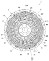
- FIG. 1 is an axial view of the power unit of the embodiment.
- FIG. 2 is a cross-sectional view taken along line II-II of FIG.
- the rotating electric machine 1 is an inner rotor type three-phase permanent magnet synchronous motor.
- the rotary electric machine 1 is, for example, a running motor mounted on a vehicle such as an electric motorcycle.
- the rotary electric machine 1 includes a cylindrical rotor 2 , a stator 3 surrounding the rotor 2 , a rotary shaft 4 fixed to the rotor 2 , and a motor case 102 housing the rotor 2 and the stator 3 .
- the rotating electric machine 1 is part of the power unit 100 .
- the power unit 100 includes a rotating electrical machine 1 , a speed reducer (not shown) that reduces and outputs the driving rotation of the rotating electrical machine 1 , and a power unit case 101 that forms an outer shell of the power unit 100 .
- Power unit case 101 will be described later.
- the rotor 2, the stator 3 and the rotating shaft 4 are arranged with the axis C as a common axis.
- the direction in which the axis C extends will be referred to as the axial direction
- the direction orthogonal to the axis C will be referred to as the radial direction
- the direction of rotation around the axis C will be referred to as the circumferential direction.
- the rotor 2 is an embedded magnet type rotor.
- the rotor 2 is rotatable around an axis C.
- the rotor 2 includes permanent magnets 10 and a rotor core 11 that holds the permanent magnets 10 .
- the rotor core 11 is formed in a cylindrical shape extending in the axial direction.
- the rotor core 11 is formed, for example, by laminating a plurality of electromagnetic steel sheets in the axial direction.
- the rotor core 11 may be a so-called dust core obtained by compression-molding metal magnetic powder (soft magnetic powder).
- the outer peripheral portion of rotor core 11 holds permanent magnets 10 .
- the outer peripheral portion has a plurality of magnetic pole portions 12 .
- the magnetic pole portions 12 are provided evenly in the circumferential direction.
- a pair of magnet slots 13 into which the permanent magnets 10 are inserted are formed in each magnetic pole portion 12 .
- the magnet slot 13 axially penetrates the rotor core 11 .
- the permanent magnet 10 is a rare earth magnet. Examples of rare earth magnets include neodymium magnets, samarium cobalt magnets, praseodymium magnets, and the like.
- the permanent magnets 10 are inserted into the respective magnet slots 13 of the rotor core 11 and fixed to the rotor core 11 by, for example, resin or adhesive.
- the permanent magnet 10 is radially magnetized.
- the permanent magnet 10 is arranged such that the magnetization directions of the plurality of magnetic pole portions 12 are alternately reversed in the circumferential direction.
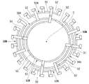
- FIG. 3 is an axial view of the rotor and stator of the embodiment.
- the stator 3 is a three-phase Y-connection salient pole stator.
- Stator 3 includes stator core 20 , insulator 30 , coils 40U, 40V, 40W, bus bars 50N, 50U, 50V, 50W, and holding portion 80 .
- the stator core 20 is formed by annularly arranging a plurality of (12 in this embodiment) split cores 22 along the circumferential direction.
- the split cores 22 are configured by laminating a plurality of T-shaped electromagnetic steel sheets punched out by pressing.
- the split core 22 includes back yoke pieces 23 extending along the circumferential direction and teeth 24 extending radially inward from the back yoke pieces 23 .
- the back yoke pieces 23 form the annular back yoke 21 of the stator core 20 by connecting the split cores 22 in the circumferential direction.
- the teeth 24 form slots 26 between adjacent teeth 24 by connecting the split cores 22 in the circumferential direction.
- a radially inner end of the tooth 24 faces the magnetic pole portion 12 (see FIG. 1) of the rotor 2 .
- the split cores 22 connected in the circumferential direction are fixed to each other by a stator ring 28 (see FIG. 1).
- FIG. 4 is a perspective view showing an insulator and a holding portion according to the embodiment; As shown in FIGS. 3 and 4 , the insulator 30 is attached to each split core 22 so as to surround the teeth 24 .
- the insulator 30 is made of an electrical insulating material such as resin.
- the insulator 30 is divided into two parts, a first insulator 30A and a second insulator 30B. The dividing position of the first insulator 30A and the second insulator 30B is in the axial intermediate portion of the teeth 24 .
- the intermediate portion may be positioned between one axial end and the other axial end of the teeth 24 .
- the first insulator 30 ⁇ /b>A covers end faces of the teeth 24 facing the first axial direction and portions of both side faces facing the circumferential direction in the first axial direction.
- the second insulator 30B covers the end faces of the teeth 24 facing the second axial direction and the second axial direction portions of both side faces facing the circumferential direction.
- the insulator 30 includes an inner peripheral wall 31 along the outer peripheral surface of the tooth 24 , an inner flange 32 projecting from the radially inner edge of the inner peripheral wall 31 , and an outer flange 33 projecting from the radially outer edge of the inner peripheral wall 31 . And prepare. These inner peripheral wall 31, inner flange 32 and outer flange 33 are formed on both the first insulator 30A and the second insulator 30B. The inner peripheral wall 31, the inner flange 32 and the outer flange 33 are arranged so as to surround the teeth 24 over the entire circumference except for the dividing positions of the first insulator 30A and the second insulator 30B.
- the inner peripheral wall 31, the inner flange 32 and the outer flange 33 are formed integrally with each of the first insulator 30A and the second insulator 30B. Between the inner flange 32 and the outer flange 33, a winding groove 34 is formed in which the coils 40U, 40V, 40W wound around the inner peripheral wall 31 are arranged.
- a turn locking portion 36 and a pair of slits 37 are formed in the first insulator 30A.
- the turn locking portion 36 is a convex portion protruding from the outer flange 33 .
- the turn locking portion 36 protrudes in the first direction from the edge of the outer flange 33 in the first direction in the axial direction.
- a slit 37 is formed in the inner flange 32 .
- the slit 37 is formed at the edge of the inner flange 32 in the first axial direction.
- the slits 37 are formed at intervals in the circumferential direction.
- the coils 40U, 40V, and 40W are formed by winding windings 41 around the teeth 24 with insulators 30 interposed therebetween.
- Coils 40U, 40V, 40W are wound around inner peripheral wall 31 of insulator 30 and positioned between inner flange 32 and outer flange 33 .
- Coils 40U, 40V, and 40W are a U-phase coil 40U, a V-phase coil 40V, and a W-phase coil 40W arranged with a phase difference of 120° relative to each other in the circumferential direction.
- U-phase coil 40U, V-phase coil 40V, and W-phase coil 40W are arranged in this order in the circumferential direction.
- each coil 40U, 40V, 40W is electrically commonly connected to the neutral point of the Y-connection.
- the other end of each coil 40U, 40V, 40W is electrically commonly connected to each phase wire of a three-phase line 60, which will be described later.
- FIG. 5 is a perspective view showing the essential parts of the stator of the embodiment.
- the winding 41 includes a pair of lead portions 42, 43 extending radially inward from the coils 40U, 40V, 40W.
- the pair of lead-out portions 42 and 43 are formed from the first lead-out portion 42 extending from the winding end portions of the coils 40U, 40V, and 40W toward the first end portion 41a of the winding 41 and the second end portion 41b of the winding 41. and a second lead-out portion 43 extending toward the winding start portions of the coils 40U, 40V, and 40W.
- the first lead-out portion 42 and the second lead-out portion 43 extend from the winding groove 34 in the first axial direction.
- the first lead-out portion 42 passes through one slit 37 of the first insulator 30A.
- a portion of the first lead-out portion 42 closer to the coils 40U, 40V, and 40W than the slit 37 is wound around the turn locking portion 36 of the first insulator 30A once.
- the second lead-out portion 43 passes through the other slit 37 of the first insulator 30A.
- FIG. 6 is an axial view of the bus bar of the embodiment.
- bus bars 50N, 50U, 50V and 50W electrically connect coils 40U, 40V and 40W.
- the busbars 50N, 50U, 50V, 50W are a neutral point busbar 50N, a U-phase busbar 50U, a V-phase busbar 50V, and a W-phase busbar 50W.
- the neutral point bus bar 50N is connected to the first ends 41a of the windings 41 forming the coils 40U, 40V, 40W.
- the neutral point busbars 50N are arranged in the circumferential direction so as to be connected one by one to the windings 41 of the U-phase coil 40U, the V-phase coil 40V, and the W-phase coil 40W, which are consecutively arranged in the circumferential direction. .
- four neutral point bus bars 50N are provided.
- U-phase bus bar 50U is connected to second ends 41b of all windings 41 forming U-phase coil 40U.
- the V-phase bus bar 50V is connected to the second ends 41b of all the windings 41 forming the V-phase coil 40V.
- the W-phase bus bar 50W is connected to the second ends 41b of all the windings 41 forming the W-phase coil 40W.
- These busbars 50N, 50U, 50V, 50W are arranged inside insulators 30 arranged annularly when viewed from the axial direction.
- Bus bars 50N, 50U, 50V, and 50W are made of metal plates.
- Bus bars 50N, 50U, 50V, and 50W include winding connection portions 52 connected to windings 41 and connecting portions 51 connecting winding connection portions 52 .
- FIG. 7 is a perspective view showing a busbar for each phase of the embodiment.
- the connecting portion 51 has a thickness in the radial direction and extends with a substantially constant width along the circumferential direction.
- the connecting portions 51 of the neutral point bus bars 50N are arranged at regular intervals along the circumferential direction.
- the connecting portions 51 of the neutral point bus bar 50N, the U-phase bus bar 50U, the V-phase bus bar 50V and the W-phase bus bar 50W are radially spaced apart at predetermined positions in the axial direction.
- connecting portion 51 of W-phase bus bar 50W, connecting portion 51 of V-phase bus bar 50V, connecting portion 51 of U-phase bus bar 50U, and connecting portion 51 of neutral point bus bar 50N. are placed.
- Connecting portions 51 of neutral point bus bar 50N, U-phase bus bar 50U, V-phase bus bar 50V, and W-phase bus bar 50W have radii of curvature corresponding to their positions in the radial direction so as not to cross each other.
- the winding connection portion 52 is connected to the winding 41 .
- the winding connection portion 52 extends radially outward from the connecting portion 51 when viewed in the axial direction.
- the winding connection portion 52 is formed integrally with the connection portion 51 .
- the neutral point busbar 50N is connected to each of the windings 41 of the coils 40U, 40V, and 40W of each phase. It extends three from 51.
- four coils 40U, 40V, 40W are provided for each phase, four winding connection portions 52 extend from the connecting portions 51 in the bus bars 50U, 50V, 50W for each phase. there is
- the winding connection portion 52 extends axially outward (first direction) from the connecting portion 51, then bends radially outward and extends radially outward.
- a radially outer tip portion of the winding connection portion 52 is positioned radially outwardly of a plurality of holding grooves 83 described later and is close to the inner flange 32 of the insulator 30 .
- the tip portion of the winding connection portion 52 is folded outward in the axial direction to sandwich the winding 41 .
- the winding connection portion 52 of the neutral point bus bar 50N sandwiches the first end portion 41a of the winding 41 therebetween.
- the winding connection portions 52 of the bus bars 50U, 50V, and 50W of each phase sandwich the second end portion 41b of the winding 41 .
- the neutral point bus bar 50N electrically connects the U-phase coil 40U, the V-phase coil 40V, and the W-phase coil 40W that are continuously arranged along the circumferential direction.
- the bus bars 50U, 50V, 50W of each phase electrically connect the coils 40U, 40V, 40W of the same phase.
- each phase bus bar 50 U, 50 V, 50 W further includes a three-phase line connection portion 53 extending from the connection portion 51 .
- the three-phase line connection portion 53 extends outward along the axial direction from the intermediate portion of the connecting portion 51 .
- the three-phase line connection portion 53 is formed integrally with the connecting portion 51 .
- the entire three-phase line connection portion 53 has a thickness in the radial direction.
- a through hole 53 h is formed in the three-phase line connection portion 53 .
- the through hole 53h radially penetrates the axially outer tip of the three-phase line connection portion 53 .
- a shaft portion of a bolt 71 for fastening a terminal 61 of the three-phase line 60 is inserted through the through hole 53h.
- the three-phase line connection portion 53 has an engaging portion 54 that engages with the terminal 61 of the three-phase line 60 .
- the engaging portion 54 protrudes in the circumferential direction.
- the engaging portions 54 of the U-phase bus bar 50U and the W-phase bus bar 50W protrude clockwise when viewed from the extension direction (first direction) of the three-phase line connection portion 53 in the axial direction.
- the engaging portion 54 of the V-phase bus bar 50V protrudes counterclockwise when viewed from the extending direction of the three-phase line connecting portion 53 in the axial direction.
- Three-phase line connection portions 53 of U-phase bus bar U, V-phase bus bar 50V, and W-phase bus bar 50W are arranged circumferentially offset from each other.
- a terminal 61 of a three-phase line 60 is connected to the three-phase line connection portion 53 .
- a terminal 61 for the three-phase line is provided for each phase.
- the terminals 61 are formed in the same shape.
- the terminal 61 is made of metal.
- the terminal 61 includes a fastening portion 62 fastened to the three-phase line connection portion 53, and a crimped portion 65 mechanically and electrically connected to the fastening portion 62 and coupled to the tip of the electric wire of the three-phase line 60.
- the fastening portion 62 includes a base portion 63 that overlaps the tip portion of the three-phase line connection portion 53 and a pair of side portions 64 that extend from the base portion 63 in the same direction.
- the base portion 63 overlaps the tip portion of the three-phase line connection portion 53 from the outside in the radial direction.
- the base portion 63 is formed with a through hole (not shown) concentric with the through hole 53h passing through the three-phase line connection portion 53 .
- the pair of side portions 64 extends from both circumferential side edges of the base portion 63 .
- the pair of side portions 64 extend toward the axis C so as to be inclined at approximately 90° with respect to the base portion 63 .
- the pair of side portions 64 are arranged so as to sandwich the tip portion of the three-phase line connection portion 53 from the outside in the circumferential direction.
- One side portion 64 of the pair of side portions 64 is in contact with the engaging portion 54 of the three-phase line connection portion 53 in the clockwise direction around the through hole 53h when viewed from the outside in the radial direction.
- a crimping portion 65 is connected to the other side portion 64 of the pair of side portions 64 .
- the electric wire of the three-phase line 60 is connected to the crimped portion 65 so as to extend in the opposite direction to the engaging portion 54 with the front end portion of the three-phase line connection portion 53 as the center.
- the three-phase line connection portion 53 and the terminal 61 of the three-phase line 60 are radially fastened by a fastening member set 70 .
- the fastening member set 70 has a bolt 71 (first fastening member) and a nut 72 (second fastening member) screwed onto the bolt 71 .
- the bolt 71 is inserted through the through hole 53h of the three-phase line connection portion 53 and the through hole of the terminal 61 from the radially outer side.
- Nut 72 is a square nut. The nut 72 is screwed onto the shaft portion of the bolt 71 with the base portion 63 of the terminal 61 and the three-phase line connection portion 53 sandwiched between the nut 72 and the head portion of the bolt 71 .
- the nut 72 abuts against the pair of side portions 64 of the terminal 61 in the clockwise direction around the through hole 53h when viewed from the radially outer side.
- the clockwise direction around the through hole 53h as seen from the radially outer side is the direction of rotation when the bolt 71 is screwed.
- the holding portion 80 is provided for each of the coils 40U, 40V and 40W.
- the holding portion 80 is integrally provided with the first insulator 30A by being molded integrally with the first insulator 30A.
- the holding portion 80 is arranged radially inward of the stator core 20 in the first axial direction with respect to the rotor 2 .
- the plurality of holding portions 80 are arranged annularly along the circumferential direction.
- the holding portion 80 holds the connecting portions 51 of the plurality of busbars 50N, 50U, 50V, 50W while being spaced apart from each other in the radial direction.
- the holding portion 80 includes a bottom portion 81 extending radially inward from the inner flange 32 of the insulator 30 and an insulating wall 82 rising axially outward (first direction) from the bottom portion 81 .
- Bottom portion 81 extends along an end surface of rotor core 11 in the first axial direction.
- the bottom portion 81 extends radially inward from the inner flange 32 while narrowing in width in the circumferential direction when viewed in the axial direction.
- a plurality of insulating walls 82 are formed for each holding portion 80 . In this embodiment, five insulating walls 82 are formed for each holding portion 80 .
- the insulating walls 82 extend in an arc shape along the circumferential direction and are spaced apart from each other in the radial direction.
- Holding grooves 83 in which connecting portions 51 of busbars 50N, 50U, 50V, and 50W are arranged are formed between insulating walls 82 adjacent in the radial direction.
- the holding groove 83 is open in the first axial direction and extends in an arc shape along the circumferential direction. By arranging all the holding portions 80 in an annular shape, the holding grooves 83 extend in an annular shape as a whole. In this embodiment, four holding grooves 83 are formed along the radial direction.
- the connecting portions 51 of the bus bars 50U, 50V, and 50W of the respective phases are arranged in the three holding grooves 83 positioned radially inward among the four holding grooves 83 .
- connection portion 51 of the neutral point bus bar 50N is arranged in the holding groove 83 positioned radially outermost among the four holding grooves 83 .
- the insulating wall 82 is interposed between the plurality of busbars 50N, 50U, 50V, 50W.
- a first insulating wall, a second insulating wall, a third insulating wall, a fourth insulating wall, and a It is called the fifth insulating wall.
- the fourth insulating wall 82 is formed higher than the second insulating wall 82 and the third insulating wall 82 with respect to the bottom portion 81 . Specifically, the edge of the fourth insulating wall 82 in the first axial direction is greater than the edge in the first axial direction of each of the second insulating wall 82 and the third insulating wall 82 . located in the direction The edge of the fourth insulating wall 82 in the first axial direction is in contact with the winding connection portion 52 in the first axial direction.
- the holding portion 80 has a first contact portion 85 (contact portion) that contacts the winding connection portions 52 of the busbars 50U, 50V, and 50W of each phase, and the winding connection portion 52 of the neutral point busbar 50N. and a second contact portion 86 .
- the first contact portion 85 protrudes in the axial direction from the edge of the fourth insulating wall 82 in the first axial direction.
- the first contact portion 85 contacts the winding connection portions 52 of the bus bars 50U, 50V, and 50W of each phase from one side in the circumferential direction. Thereby, the first contact portions 85 position the winding connection portions 52 of the bus bars 50U, 50V, and 50W of the respective phases in the circumferential direction.
- the second contact portion 86 protrudes in the axial direction from the edge of the fifth insulating wall 82 in the first axial direction.
- the second contact portion 86 is displaced from the first contact portion 85 in one direction in the circumferential direction.
- the second contact portion 86 contacts the winding connection portion 52 of the neutral point bus bar 50N from one side in the circumferential direction. Thereby, the second contact portion 86 positions the winding connection portion 52 of the neutral point bus bar 50N in the circumferential direction.
- a through hole 87 is formed in the holding portion 80 .
- a through hole 87 is formed between the fifth insulating wall 82 and the inner flange 32 .
- the through hole 87 axially penetrates the holding portion 80 .
- a pair of through holes 87 are formed in each holding portion 80 at intervals in the circumferential direction.
- the through hole 87 overlaps the tip of the winding connection portion 52 when viewed in the axial direction.
- one of the pair of through holes 87 overlaps the connecting portion between the winding connection portion 52 of the neutral point bus bar 50N and the first end portion 41a of the winding 41 when viewed from the axial direction.
- the other of the pair of through-holes 87 overlaps the connecting portion between the winding connection portion 52 of each phase bus bar 50U, 50V, 50W and the second end portion 41b of the winding 41 when viewed in the axial direction.
- the power unit case includes the motor case 102 described above and a speed reducer case 103 that houses a speed reducer.
- Motor case 102 and reduction gear case 103 are arranged in the axial direction.
- a rotary shaft 4 fixed to the rotor 2 passes through a partition wall 104 that separates the inner space of the motor case 102 and the inner space of the speed reducer case 103 .
- the motor case 102 has a case main body 105 (casing) that opens on the side opposite to the speed reducer case 103 in the axial direction.
- the outer peripheral portion of the stator core 20 is fastened and fixed to the case main body 105 from the side opposite to the speed reducer case 103 .
- Rotor 2 and stator 3 are arranged such that holding portion 80 is positioned between case body 105 and rotor 2 . That is, holding portion 80 and bus bars 50N, 50U, 50V, and 50W are arranged between rotor 2 and reduction gear case 103 in the axial direction.
- the opening of case body 105 is closed by a cover (not shown).
- the rotary electric machine 1 of the present embodiment is integrally provided with the plurality of bus bars 50N, 50U, 50V, and 50W electrically connecting the coils 40U, 40V, and 40W, and the insulator 30, and a holding portion 80 that holds the plurality of busbars 50N, 50U, 50V, 50W while being spaced apart from each other in the radial direction, and arranged radially inward of the stator core 20 .
- the holding portion 80 for holding the busbars 50N, 50U, 50V, and 50W is provided integrally with the insulator 30, the parts for holding the busbars are provided separately from the insulators. You can reduce your score.
- the bus bars 50N, 50U, 50V and 50W can be provided while reducing the manufacturing cost. Moreover, by arranging the holding portion 80 radially inward of the stator core 20 , it is possible to prevent the rotary electric machine 1 from increasing in size in the radial direction. Therefore, the rotary electric machine 1 can be miniaturized.
- the holding portion 80 has insulating walls 82 interposed between the plurality of busbars 50N, 50U, 50V, and 50W. According to this configuration, the bus bars 50N, 50U, 50V, and 50W can be insulated from each other by the holding portion without using a separate member such as a spacer. Therefore, the number of parts can be reduced, and the manufacturing cost can be reduced.
- the winding 41 includes lead portions 42 and 43 extending radially inward from the coils 40U, 40V and 40W and connected to any one of the plurality of bus bars 50N, 50U, 50V and 50W.
- the insulator 30 is formed with a slit 37 through which the lead portions 42 and 43 pass. According to this configuration, the draw-out portions 42 and 43 of the winding 41 can be positioned with respect to the holding portion 80 integrated with the insulator 30, so that the bus bars 50N, 50U, 50V and 50W held by the holding portion 80 can be wound.
- the wire 41 can be routed easily.
- Each of the plurality of busbars 50U, 50V, 50W has a winding connection portion 52 extending radially outward and connected to the winding 41 .
- the holding portion 80 is formed with a plurality of holding grooves 83 in which the plurality of busbars 50U, 50V, and 50W are separately arranged.
- the holding portion 80 has a first contact portion 85 that contacts the winding connection portion 52 radially outside the plurality of holding grooves 83 . According to this configuration, the first abutment portions 85 are arranged radially outside the connecting portions 51 of the busbars 50U, 50V, and 50W held in the plurality of holding grooves 83, respectively.
- the winding connection portions 52 of the bus bars 50U, 50V, and 50W connected to the coils 40U, 40V, and 40W of any phase can be positioned by the contact portions 85 using the holding portions 80 having the same structure. Therefore, it is not necessary to use the insulator 30 integrated with the holding portion 80 according to the phases of the coils 40U, 40V, and 40W, and the parts in which the insulator 30 and the holding portion 80 are integrated can be shared. Therefore, it is possible to suppress an increase in the number of types of parts and reduce the manufacturing cost.
- the holding portion 80 is arranged between the rotor 2 and the case body 105 of the motor case 102 . If the holding portion were to be placed on the opposite side of the case body 105 with the rotor 2 interposed therebetween, the holding portion would be an obstacle, making it difficult to post-assemble the rotor 2 with the stator core fixed to the case body 105. . According to this embodiment, the holding portion 80 is not arranged in the region through which the rotor 2 passes during the process of assembling the rotor 2 at the predetermined position. As a result, the rotor 2 can be assembled while the stator core 20 is fixed to the case body 105 . Therefore, the manufacturing cost can be reduced by simplifying the manufacturing process.
- the busbars 50U, 50V, 50W have a three-phase line connection portion 53 that extends along the axial direction and is connected to the three-phase line 60.
- the three-phase line 60 is radially fastened to the three-phase line connection portion 53 . If the three-phase wire connecting portion and the three-phase wire are to be fastened in the axial direction, the connecting portion between the three-phase wire connecting portion and the three-phase wire is further axially extended from the three-phase wire connecting portion extending along the axial direction.
- the connecting portion between the three-phase line connecting portion and the three-phase line may be enlarged in the radial direction or the axial direction.
- the three-phase wire connection portion 53 and the three-phase wire connection portion 60 can be arranged in the limited space between the rotor 2 and the case body 105 . Further, in the space near the axis C, the connecting portions of the three-phase line connection portion 53 and the three-phase line 60 can be prevented from interfering with other components such as the rotating shaft 4 fixed to the rotor 2 . Therefore, the enlargement of the distance between the rotor 2 and the case main body 105 can be suppressed, and the size of the rotary electric machine 1 can be reduced.
- the three-phase line 60 has a terminal 61 that is fastened to the three-phase line connection portion 53 .
- the three-phase line connection portion 53 includes an engaging portion 54 that engages with the terminal 61 .
- the terminal 61 contacts the engaging portion 54 in the rotational direction of the bolt 71 . According to this configuration, when the bolt 71 is rotated to fasten the terminal 61 to the three-phase line connection portion 53, the terminal 61 is brought into contact with the engaging portion 54 of the three-phase line connection portion 53, thereby Co-rotation of the terminal 61 with respect to the line connection portion 53 is restricted, and the three-phase line connection portion 53 and the terminal 61 can be positioned relative to each other.
- the rotation of the nut 72 is restricted by the terminal 61 , so the bolt 71 can be screwed onto the nut 72 simply by rotating the bolt 71 . Therefore, simplification of the manufacturing process can be achieved.
- the rotary electric machine 1 is a three-phase permanent magnet synchronous motor having an inner rotor of an embedded magnet type, but the scope of application of the present invention is not limited to this.
- the rotating electric machine may be a motor having a surface magnet type inner rotor in which magnets are attached to the outer peripheral surface of the rotor core.
- the present invention provides a motor having a plurality of bus bars for electrically connecting coils, such as a three-phase AC motor other than a three-phase permanent magnet synchronous motor, a brushless DC motor, etc., and a configuration similar to those motors. It is also applicable to generators with
- the neutral point bus bar 50N and the bus bars 50U, 50V, and 50W of each phase in the holding portion are not particularly limited.
- the connecting portion of the neutral point bus bar may be arranged radially inside the connecting portion of the bus bar of each phase.
- the terminal 61 is superimposed on the three-phase line connection portion 53 from the outside in the radial direction at the connection portion between the busbars 50U, 50V, and 50W and the three-phase line 60, and then the bolt 71 is installed radially. It is screwed from the outside of the direction. Co-rotation of the terminal 61 is restricted by bringing the side portion 64 of the terminal 61 into contact with the engaging portion 54 of the three-phase line connection portion 53 in the rotational direction when the bolt 71 is screwed.
- the structure of the bus bar and the connecting portion of the three-phase line is not particularly limited.
- the terminals may overlap from the inside in the radial direction with respect to the three-phase line connection portion.
- the first contact portions 85 that contact the winding connection portions 52 of the busbars 50U, 50V, and 50W of each phase are formed on the fourth insulating wall 82, but the configuration is not limited to this.
- the first contact portion may be formed on the fifth insulating wall.
Landscapes
- Engineering & Computer Science (AREA)
- Power Engineering (AREA)
- Manufacturing & Machinery (AREA)
- Insulation, Fastening Of Motor, Generator Windings (AREA)
Priority Applications (3)
| Application Number | Priority Date | Filing Date | Title |
|---|---|---|---|
| CN202180095996.7A CN116982242A (zh) | 2021-03-31 | 2021-03-31 | 旋转电机 |
| PCT/JP2021/013911 WO2022208762A1 (ja) | 2021-03-31 | 2021-03-31 | 回転電機 |
| JP2023510053A JP7728332B2 (ja) | 2021-03-31 | 2021-03-31 | 回転電機 |
Applications Claiming Priority (1)
| Application Number | Priority Date | Filing Date | Title |
|---|---|---|---|
| PCT/JP2021/013911 WO2022208762A1 (ja) | 2021-03-31 | 2021-03-31 | 回転電機 |
Publications (1)
| Publication Number | Publication Date |
|---|---|
| WO2022208762A1 true WO2022208762A1 (ja) | 2022-10-06 |
Family
ID=83458209
Family Applications (1)
| Application Number | Title | Priority Date | Filing Date |
|---|---|---|---|
| PCT/JP2021/013911 Ceased WO2022208762A1 (ja) | 2021-03-31 | 2021-03-31 | 回転電機 |
Country Status (3)
| Country | Link |
|---|---|
| JP (1) | JP7728332B2 (https=) |
| CN (1) | CN116982242A (https=) |
| WO (1) | WO2022208762A1 (https=) |
Cited By (1)
| Publication number | Priority date | Publication date | Assignee | Title |
|---|---|---|---|---|
| EP4580009A1 (en) * | 2023-12-28 | 2025-07-02 | Toyota Jidosha Kabushiki Kaisha | Motor |
Citations (6)
| Publication number | Priority date | Publication date | Assignee | Title |
|---|---|---|---|---|
| JP2011244627A (ja) * | 2010-05-19 | 2011-12-01 | Toyota Motor Corp | 固定子製造方法 |
| JP2012130179A (ja) * | 2010-12-16 | 2012-07-05 | Honda Motor Co Ltd | ステータ |
| WO2013077190A1 (ja) * | 2011-11-22 | 2013-05-30 | 本田技研工業株式会社 | 回転電機 |
| JP2013240128A (ja) * | 2012-05-11 | 2013-11-28 | Honda Motor Co Ltd | モータのステータ |
| US20140015349A1 (en) * | 2012-07-11 | 2014-01-16 | Remy Technologies, Llc | Interlocking coil isolators for resin retention in a segmented stator assembly |
| JP2019097261A (ja) * | 2017-11-20 | 2019-06-20 | 株式会社ミツバ | ブラシレスモータ |
Family Cites Families (5)
| Publication number | Priority date | Publication date | Assignee | Title |
|---|---|---|---|---|
| JP4077673B2 (ja) * | 2002-07-17 | 2008-04-16 | 本田技研工業株式会社 | 回転電機 |
| JP5094505B2 (ja) * | 2008-03-28 | 2012-12-12 | 三洋電機株式会社 | 電動機 |
| JP2014050187A (ja) * | 2012-08-30 | 2014-03-17 | Asmo Co Ltd | ステータ、ステータの製造方法及びブラシレスモータ |
| DE112016007442T5 (de) * | 2016-11-16 | 2019-08-14 | Mitsubishi Electric Corporation | Drehende elektrische Maschine |
| JP6676099B2 (ja) * | 2018-05-18 | 2020-04-08 | 三菱電機株式会社 | 回転電機 |
-
2021
- 2021-03-31 JP JP2023510053A patent/JP7728332B2/ja active Active
- 2021-03-31 WO PCT/JP2021/013911 patent/WO2022208762A1/ja not_active Ceased
- 2021-03-31 CN CN202180095996.7A patent/CN116982242A/zh active Pending
Patent Citations (6)
| Publication number | Priority date | Publication date | Assignee | Title |
|---|---|---|---|---|
| JP2011244627A (ja) * | 2010-05-19 | 2011-12-01 | Toyota Motor Corp | 固定子製造方法 |
| JP2012130179A (ja) * | 2010-12-16 | 2012-07-05 | Honda Motor Co Ltd | ステータ |
| WO2013077190A1 (ja) * | 2011-11-22 | 2013-05-30 | 本田技研工業株式会社 | 回転電機 |
| JP2013240128A (ja) * | 2012-05-11 | 2013-11-28 | Honda Motor Co Ltd | モータのステータ |
| US20140015349A1 (en) * | 2012-07-11 | 2014-01-16 | Remy Technologies, Llc | Interlocking coil isolators for resin retention in a segmented stator assembly |
| JP2019097261A (ja) * | 2017-11-20 | 2019-06-20 | 株式会社ミツバ | ブラシレスモータ |
Cited By (2)
| Publication number | Priority date | Publication date | Assignee | Title |
|---|---|---|---|---|
| EP4580009A1 (en) * | 2023-12-28 | 2025-07-02 | Toyota Jidosha Kabushiki Kaisha | Motor |
| JP2025104507A (ja) * | 2023-12-28 | 2025-07-10 | トヨタ自動車株式会社 | モータ |
Also Published As
| Publication number | Publication date |
|---|---|
| JP7728332B2 (ja) | 2025-08-22 |
| CN116982242A (zh) | 2023-10-31 |
| JPWO2022208762A1 (https=) | 2022-10-06 |
Similar Documents
| Publication | Publication Date | Title |
|---|---|---|
| CN102801242B (zh) | 旋转电机 | |
| JP6068953B2 (ja) | 電動モータ | |
| EP3176912B1 (en) | Stator and rotating machine | |
| JP4331231B2 (ja) | ステータおよび回転電機 | |
| JP6720306B2 (ja) | 回転電機の固定子 | |
| JP5734794B2 (ja) | ステータおよびこのステータを備える回転電機 | |
| JP4914288B2 (ja) | バスバーユニット | |
| US20180175570A1 (en) | Bus bar unit and rotary electric machine having the same | |
| JP4971025B2 (ja) | 回転電機用ステータ | |
| WO2020246406A1 (ja) | ステータ、モータ及びステータの製造方法 | |
| KR20060131282A (ko) | 부등슬롯형 스테이터 및 이를 구비한 하이브리드 인덕션모터 | |
| CN104364996B (zh) | 旋转电机、旋转电机用定子和车辆 | |
| JP2017046508A (ja) | 回転電機およびその製造方法 | |
| JP7728332B2 (ja) | 回転電機 | |
| JP6279122B1 (ja) | 回転電機 | |
| JP6660606B2 (ja) | 回転電機、回転電機の製造方法 | |
| JP7280070B2 (ja) | ステータ及びブラシレスモータ | |
| WO2024122140A1 (ja) | モータ | |
| JP4547228B2 (ja) | 3相回転電機 | |
| JP2018153040A (ja) | 回転電機 | |
| JP2023047885A (ja) | 回転電機 | |
| JP2018137836A (ja) | ステータおよび回転電機 | |
| JP7735694B2 (ja) | モータ | |
| US20250253720A1 (en) | Stator and motor | |
| JP7423930B2 (ja) | スロットレス回転電機、及びスロットレス回転電機の製造方法 |
Legal Events
| Date | Code | Title | Description |
|---|---|---|---|
| 121 | Ep: the epo has been informed by wipo that ep was designated in this application |
Ref document number: 21934928 Country of ref document: EP Kind code of ref document: A1 |
|
| DPE1 | Request for preliminary examination filed after expiration of 19th month from priority date (pct application filed from 20040101) | ||
| WWE | Wipo information: entry into national phase |
Ref document number: 2023510053 Country of ref document: JP |
|
| WWE | Wipo information: entry into national phase |
Ref document number: 202180095996.7 Country of ref document: CN |
|
| WWE | Wipo information: entry into national phase |
Ref document number: 202347064177 Country of ref document: IN |
|
| NENP | Non-entry into the national phase |
Ref country code: DE |
|
| 122 | Ep: pct application non-entry in european phase |
Ref document number: 21934928 Country of ref document: EP Kind code of ref document: A1 |