WO2022201666A1 - ウエハ裏面洗浄装置 - Google Patents
ウエハ裏面洗浄装置 Download PDFInfo
- Publication number
- WO2022201666A1 WO2022201666A1 PCT/JP2021/045925 JP2021045925W WO2022201666A1 WO 2022201666 A1 WO2022201666 A1 WO 2022201666A1 JP 2021045925 W JP2021045925 W JP 2021045925W WO 2022201666 A1 WO2022201666 A1 WO 2022201666A1
- Authority
- WO
- WIPO (PCT)
- Prior art keywords
- wafer
- cleaning
- back surface
- hand
- cleaning water
- Prior art date
- Legal status (The legal status is an assumption and is not a legal conclusion. Google has not performed a legal analysis and makes no representation as to the accuracy of the status listed.)
- Ceased
Links
Images



Classifications
-
- H—ELECTRICITY
- H10—SEMICONDUCTOR DEVICES; ELECTRIC SOLID-STATE DEVICES NOT OTHERWISE PROVIDED FOR
- H10P—GENERIC PROCESSES OR APPARATUS FOR THE MANUFACTURE OR TREATMENT OF DEVICES COVERED BY CLASS H10
- H10P72/00—Handling or holding of wafers, substrates or devices during manufacture or treatment thereof
- H10P72/04—Apparatus for manufacture or treatment
- H10P72/0402—Apparatus for fluid treatment
- H10P72/0406—Apparatus for fluid treatment for cleaning followed by drying, rinsing, stripping, blasting or the like
- H10P72/0411—Apparatus for fluid treatment for cleaning followed by drying, rinsing, stripping, blasting or the like for wet cleaning or washing
- H10P72/0412—Apparatus for fluid treatment for cleaning followed by drying, rinsing, stripping, blasting or the like for wet cleaning or washing using mainly scrubbing means, e.g. brushes
-
- B—PERFORMING OPERATIONS; TRANSPORTING
- B08—CLEANING
- B08B—CLEANING IN GENERAL; PREVENTION OF FOULING IN GENERAL
- B08B1/00—Cleaning by methods involving the use of tools
- B08B1/10—Cleaning by methods involving the use of tools characterised by the type of cleaning tool
- B08B1/14—Wipes; Absorbent members, e.g. swabs or sponges
-
- B—PERFORMING OPERATIONS; TRANSPORTING
- B08—CLEANING
- B08B—CLEANING IN GENERAL; PREVENTION OF FOULING IN GENERAL
- B08B1/00—Cleaning by methods involving the use of tools
- B08B1/10—Cleaning by methods involving the use of tools characterised by the type of cleaning tool
- B08B1/14—Wipes; Absorbent members, e.g. swabs or sponges
- B08B1/143—Wipes
-
- B—PERFORMING OPERATIONS; TRANSPORTING
- B08—CLEANING
- B08B—CLEANING IN GENERAL; PREVENTION OF FOULING IN GENERAL
- B08B1/00—Cleaning by methods involving the use of tools
- B08B1/30—Cleaning by methods involving the use of tools by movement of cleaning members over a surface
- B08B1/32—Cleaning by methods involving the use of tools by movement of cleaning members over a surface using rotary cleaning members
- B08B1/36—Cleaning by methods involving the use of tools by movement of cleaning members over a surface using rotary cleaning members rotating about an axis orthogonal to the surface
-
- B—PERFORMING OPERATIONS; TRANSPORTING
- B08—CLEANING
- B08B—CLEANING IN GENERAL; PREVENTION OF FOULING IN GENERAL
- B08B3/00—Cleaning by methods involving the use or presence of liquid or steam
- B08B3/02—Cleaning by the force of jets or sprays
-
- H—ELECTRICITY
- H10—SEMICONDUCTOR DEVICES; ELECTRIC SOLID-STATE DEVICES NOT OTHERWISE PROVIDED FOR
- H10P—GENERIC PROCESSES OR APPARATUS FOR THE MANUFACTURE OR TREATMENT OF DEVICES COVERED BY CLASS H10
- H10P52/00—Grinding, lapping or polishing of wafers, substrates or parts of devices
-
- H—ELECTRICITY
- H10—SEMICONDUCTOR DEVICES; ELECTRIC SOLID-STATE DEVICES NOT OTHERWISE PROVIDED FOR
- H10P—GENERIC PROCESSES OR APPARATUS FOR THE MANUFACTURE OR TREATMENT OF DEVICES COVERED BY CLASS H10
- H10P72/00—Handling or holding of wafers, substrates or devices during manufacture or treatment thereof
- H10P72/04—Apparatus for manufacture or treatment
- H10P72/0402—Apparatus for fluid treatment
- H10P72/0406—Apparatus for fluid treatment for cleaning followed by drying, rinsing, stripping, blasting or the like
- H10P72/0411—Apparatus for fluid treatment for cleaning followed by drying, rinsing, stripping, blasting or the like for wet cleaning or washing
- H10P72/0414—Apparatus for fluid treatment for cleaning followed by drying, rinsing, stripping, blasting or the like for wet cleaning or washing using mainly spraying means, e.g. nozzles
-
- H—ELECTRICITY
- H10—SEMICONDUCTOR DEVICES; ELECTRIC SOLID-STATE DEVICES NOT OTHERWISE PROVIDED FOR
- H10P—GENERIC PROCESSES OR APPARATUS FOR THE MANUFACTURE OR TREATMENT OF DEVICES COVERED BY CLASS H10
- H10P72/00—Handling or holding of wafers, substrates or devices during manufacture or treatment thereof
- H10P72/30—Handling or holding of wafers, substrates or devices during manufacture or treatment thereof for conveying, e.g. between different workstations
- H10P72/33—Handling or holding of wafers, substrates or devices during manufacture or treatment thereof for conveying, e.g. between different workstations into and out of processing chamber
- H10P72/3302—Mechanical parts of transfer devices
-
- H—ELECTRICITY
- H10—SEMICONDUCTOR DEVICES; ELECTRIC SOLID-STATE DEVICES NOT OTHERWISE PROVIDED FOR
- H10P—GENERIC PROCESSES OR APPARATUS FOR THE MANUFACTURE OR TREATMENT OF DEVICES COVERED BY CLASS H10
- H10P72/00—Handling or holding of wafers, substrates or devices during manufacture or treatment thereof
- H10P72/70—Handling or holding of wafers, substrates or devices during manufacture or treatment thereof for supporting or gripping
-
- H—ELECTRICITY
- H10—SEMICONDUCTOR DEVICES; ELECTRIC SOLID-STATE DEVICES NOT OTHERWISE PROVIDED FOR
- H10P—GENERIC PROCESSES OR APPARATUS FOR THE MANUFACTURE OR TREATMENT OF DEVICES COVERED BY CLASS H10
- H10P72/00—Handling or holding of wafers, substrates or devices during manufacture or treatment thereof
- H10P72/70—Handling or holding of wafers, substrates or devices during manufacture or treatment thereof for supporting or gripping
- H10P72/76—Handling or holding of wafers, substrates or devices during manufacture or treatment thereof for supporting or gripping using mechanical means, e.g. clamps or pinches
- H10P72/7602—Handling or holding of wafers, substrates or devices during manufacture or treatment thereof for supporting or gripping using mechanical means, e.g. clamps or pinches the wafers being placed on a robot blade or gripped by a gripper for conveyance
-
- H—ELECTRICITY
- H10—SEMICONDUCTOR DEVICES; ELECTRIC SOLID-STATE DEVICES NOT OTHERWISE PROVIDED FOR
- H10P—GENERIC PROCESSES OR APPARATUS FOR THE MANUFACTURE OR TREATMENT OF DEVICES COVERED BY CLASS H10
- H10P72/00—Handling or holding of wafers, substrates or devices during manufacture or treatment thereof
- H10P72/70—Handling or holding of wafers, substrates or devices during manufacture or treatment thereof for supporting or gripping
- H10P72/78—Handling or holding of wafers, substrates or devices during manufacture or treatment thereof for supporting or gripping using vacuum or suction, e.g. Bernoulli chucks
-
- B—PERFORMING OPERATIONS; TRANSPORTING
- B08—CLEANING
- B08B—CLEANING IN GENERAL; PREVENTION OF FOULING IN GENERAL
- B08B1/00—Cleaning by methods involving the use of tools
- B08B1/30—Cleaning by methods involving the use of tools by movement of cleaning members over a surface
- B08B1/32—Cleaning by methods involving the use of tools by movement of cleaning members over a surface using rotary cleaning members
Definitions
- the present invention relates to a wafer back surface cleaning apparatus that cleans the back surface of a semiconductor wafer, for example, before grinding the semiconductor wafer.
- wafers semiconductor wafers
- wafers silicon wafers
- a rotatable rotating plate is provided on the back surface side of the wafer, and a hole provided in the center of the rotating plate is provided with a wafer support mechanism and a liquid discharge port.
- the liquid ejection plate can be moved up and down to receive the wafer with the liquid ejection plate protruding upward.
- the wafer is horizontally held by the holding member, and a liquid film is formed by supplying a processing liquid or a rinsing liquid between the wafer and the rotating plate from a liquid discharge nozzle continuously provided below the liquid discharge port.
- FIG. 7 is an overall perspective view of the wafer back surface cleaning apparatus 101
- FIG. 8 is a perspective view showing the inside of the cleaning position with some components omitted.
- a wafer back surface cleaning apparatus 101 shown in FIGS. 7 and 8 includes a hand h2 that transports a wafer W before grinding with the front surface of the wafer W facing upward from the position of the alignment 102 to the cleaning position (the position shown in FIG. 7). and a hand h1 (not shown) that receives the wafer W that has been cleaned at the cleaning position and transports it to the next wafer grinding step.
- a rotating plate 103 there are a rotating plate 103, a cleaning pad 104 made of, for example, a sponge that rotates together with the rotating plate 103, and a cleaning pad 104 that supplies cleaning water (pure water) to the cleaning pad 104 during cleaning. Equipped with a water supply nozzle 105 and a wafer suction pad 106 for holding the wafer W after cleaning, and in a non-rotating position where drying air is blown to the back surface of the wafer W after cleaning, the hand h2 and the wafer suction pad 106. It has an air blower 107 provided.
- FIG. 1 An example of the operation of the wafer back surface cleaning apparatus 101 configured in this way is shown as an operation flow in FIG.
- the operation of the wafer back surface cleaning apparatus 101 will be described in order of steps S101 to S106 according to the operation flow shown in FIG.
- the hand h2 chucks (holds) the wafer W before grinding that has been transported onto the alignment 102, and the hand h2 rotates to carry the chucked wafer W directly to the cleaning position (step S101).
- the hand h2 presses the wafer W against the rotating cleaning pad 104 to perform scrub cleaning (step S102).
- the hand h2 moves away from the cleaning pad 104 while holding the wafer W. Also, at the cleaning position, the wafer suction pad 106 is raised and positioned above the cleaning pad 104 . Then, drying air is blown from the air blower 107 to the back surface of the wafer W and from the air blower 108 to the wafer suction pad 106 , respectively. and water are removed (step S103).
- step S104 the hand h2 descends, and the hand h2 once transfers the gripped wafer W onto the wafer suction pad 106 (step S104). Then, only the hand h2 rises to a predetermined position. Thereafter, in order to prevent sticking of the pad portion of the hand h2 and the surface of the wafer W due to water during transfer, dry air is blown from the air blower 107 to remove foreign matter and water adhering to the pad portion of the hand h2. be Drying air is also blown from the air blower 108 to remove foreign matter and water adhering to the surface of the wafer W (step S105).
- step S106 the wafer W on the wafer suction pad 106 is transferred to another hand h1, and the hand h1 transfers the cleaned wafer W to the next wafer grinding step (step S106). . This completes one cycle of operation.
- the front surface of the wafer W and the hand are blown with air to prevent sticking due to water.
- a second hand that holds the wafer with its surface facing upward, conveys the wafer before cleaning to a cleaning position, and transfers the wafer after cleaning to the first hand;
- a cleaning pad that is arranged at a cleaning position and is slidably contactable with the back surface of the wafer, and a cleaning water supply nozzle that discharges cleaning water onto the back surface of the wafer, wherein the second hand
- scrub cleaning the back surface of the wafer is brought into contact with the cleaning pad while the cleaning water supply nozzle is supplying cleaning water to the back surface of the wafer.
- the back surface cleaning apparatus for a wafer separates the wafer after scrub cleaning from the cleaning pad while cleaning water is being supplied to the back surface of the wafer, and transfers the wafer to the first hand after the rinse cleaning.
- the second hand grips the wafer placed at the alignment position or the like with the back surface facing down, conveys the wafer to the cleaning position, and scrubs and cleans the wafer at the cleaning position. Perform rinse cleaning.
- scrub cleaning the second hand brings the cleaning pad into contact with the back surface of the wafer while the cleaning water supply nozzle is supplying cleaning water to the back surface of the wafer.
- the scrub-cleaned wafer can be separated from the cleaning pad while cleaning water is being supplied to the rear surface of the wafer, and after rinsing, the wafer can be transferred to the first hand.
- the back surface of the wafer is scrub-cleaned with a cleaning pad such as a sponge, and as a finishing step, cleaning water is poured over the entire back surface of the wafer from a cleaning water supply nozzle to perform a rinse-cleaning process, thereby washing off the stains raised by the scrub-cleaning process. expected to be effective.
- the second hand receives the wafer from a predetermined position such as an alignment position, cleans the wafer, and then transfers the wafer to the first hand. Therefore, it is possible to prevent foreign substances from adhering again to the front and back surfaces of the wafer W during and after cleaning.
- the invention according to claim 2 provides the wafer back surface cleaning apparatus in the configuration according to claim 1, wherein the cleaning water supply nozzle obliquely discharges the cleaning water to the back surface of the wafer.
- the cleaning water supply nozzle rotates integrally with the rotary plate and discharges the cleaning water from the cleaning water supply nozzle obliquely toward the back surface of the wafer. can be spread throughout. As a result, it is possible to further remove foreign matter and the like that could not be completely removed by the scrub cleaning process by this cleaning process.
- the invention according to claim 3 provides the wafer back surface cleaning apparatus in the configuration according to claim 1 or 2, wherein the cleaning position is provided with a cylindrical cover arranged to surround the outer periphery of the wafer.
- the cylindrical cover prevents the cleaning liquid from splashing to the surface side of the wafer during the scrub cleaning process and the rinse cleaning process, respectively, and from running around to the surface side of the wafer and the second hand side. be able to.
- the invention according to claim 4 is the configuration according to claim 1, 2 or 3, wherein the first hand grips the outer peripheral portion of the wafer when receiving the wafer from the second hand. provides a wafer backside cleaning apparatus.
- the wafer after cleaning is received by the first hand from the second hand by gripping the outer peripheral portion of the wafer, thereby maintaining the state of the wafer after cleaning and performing the next grinding process. can be transported to
- the back surface of the wafer is scrub-washed with a cleaning pad such as a sponge, and then the back surface of the wafer is rinsed with cleaning water such as pure water over the entire back surface of the wafer.
- a cleaning pad such as a sponge
- cleaning water such as pure water over the entire back surface of the wafer.
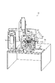
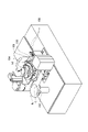
- FIG. 1 is a schematic overall perspective view of a wafer back surface cleaning apparatus shown as an example according to an embodiment of the present invention
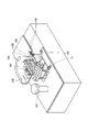
- FIG. FIG. 2 is a perspective view showing the internal structure of the same wafer back surface cleaning apparatus with a part broken away
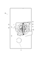
- FIG. 2 is a plan view showing the inside of the same wafer back surface cleaning apparatus with a part thereof omitted
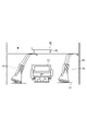
- FIG. 4 is a schematic diagram for explaining cleaning water discharge from a cleaning water supply nozzle and action of a cylindrical cover in the same wafer back surface cleaning apparatus
- FIG. 4 is an operation flow diagram showing an example of operations in the same wafer back surface cleaning apparatus
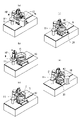
- FIG. 4 is an operation explanatory diagram of the same wafer back surface cleaning apparatus
- 1 is an overall perspective view showing an example of a conventional wafer back surface cleaning apparatus
- FIG. FIG. 8 is a perspective view showing the internal structure of the wafer back surface cleaning apparatus shown in FIG. 7, with some components omitted
- FIG. 8 is a flowchart showing an operation example of the conventional wafer back surface
- a wafer back surface cleaning apparatus comprising: a first hand for receiving the wafer after cleaning; a second hand that transfers the wafer to the first hand; a cleaning pad that is arranged at the cleaning position and is slidably contactable with the back surface of the wafer; and a cleaning water that is applied to the back surface of the wafer.
- the second hand presses the back surface of the wafer against the cleaning pad while the cleaning water supply nozzle is supplying cleaning water to the back surface of the wafer.
- the wafer after scrub cleaning is separated from the cleaning pad while the cleaning water supply nozzle is supplying cleaning water to the back surface of the wafer, and after the rinse cleaning, the wafer is This is realized by the configuration of handing over to the first hand.
- drawings may exaggerate by enlarging and exaggerating characteristic parts in order to make the features easier to understand, and the dimensional ratios, etc. of the constituent elements may not necessarily be the same as the actual ones.
- hatching of some components may be omitted in order to facilitate understanding of the cross-sectional structure of the components.
- FIG. 1 to 3 show a wafer back surface cleaning apparatus 10 according to the present invention.
- FIG. 1 is a schematic perspective view of the entire wafer back surface cleaning apparatus 10.
- FIG. FIG. 3 is a perspective view, and
- FIG. 3 is a plan view showing the inside of the wafer back surface cleaning apparatus 10 with a part omitted.
- the wafer back surface cleaning apparatus 10 is an automated apparatus that grips the wafer W before grinding from a position on the alignment 11 with the surface of the wafer W facing upward, and A hand H2 as a second hand that transports W to the cleaning position (the position shown in FIGS. 1 and 2) and holds it until the cleaning process is completed, and the wafer W that has been cleaned at the cleaning position.
- a hand H1 is provided as a first hand that receives and conveys to the next process.
- a rotating plate 12 At the cleaning position, there are provided a rotating plate 12, a cleaning pad 13 made of, for example, a sponge that rotates integrally with the rotating plate 12, and a supply of cleaning water (pure water) to the cleaning pad 13 during cleaning. and a cleaning water supply nozzle 14 for supplying cleaning water (pure water) for rinsing to the back surface of the wafer W.
- FIG. A cylindrical cover 20 is provided at the washing position so as to surround the outside of the rotating plate 12 .
- the hand H2 is equipped with a wafer suction pad 15 that serves as a ceramic porous chuck that vacuum-chucks the upper surface of the wafer W to hold it. Further, the hand H2 is capable of horizontal turning and vertical movement.
- the hand H1 carries the wafer W from a predetermined position onto the alignment 11 before processing, receives the wafer W cleaned at the cleaning position from the hand H2, holds it, and carries it to the next grinding step. have.
- the hand H1 grips the wafer W so that the front surface of the wafer W faces upward, and the outer peripheral surface of the wafer W is gripped and conveyed.
- the position of the cleaning pad 13 can be adjusted vertically with respect to the rotary plate 12 and the cleaning water supply nozzle 14 . That is, when the scrub cleaning process is performed, the cleaning water supply nozzle 14 moves to an upper position, that is, a position protruding upward from the ejection of cleaning water from the cleaning water supply nozzle 14, and the cleaning water is ejected from the outlet of the cleaning water supply nozzle 14 toward the back surface of the wafer W. Scrub cleaning is performed using the cleaning water.
- the cleaning water supply nozzle 14 moves to a lower position, that is, below the discharge of cleaning water from the cleaning water supply nozzle 14, and is arranged at a position that does not interfere with the rinse cleaning process by the cleaning water supply nozzle 14, which will be described later. be.
- a pair of cleaning water supply nozzles 14 are provided on the left and right sides of the cleaning pad 13 .
- the direction of the ejection port of the cleaning water supply nozzle 14 is set so that the cleaning water is ejected obliquely downward to the back surface of the wafer W, as shown in detail in FIG.
- the cleaning water is discharged and sprayed onto the back surface of the wafer W.
- the cleaning water flows along the entire back surface of the wafer W, so that the cleaning water can be distributed over the entire back surface of the wafer W.
- FIG. Although a pair of cleaning water supply nozzles 14 are provided on the left and right sides of the cleaning pad 13, the structure may be such that only one nozzle is provided on one side.
- the cover 20 is a cylindrical cover made by molding plastic such as polyvinyl chloride (PVC), fixed to the rotating plate 12, and rotated integrally.
- the inner diameter of the cover 20 is slightly larger than the outer diameter of the wafer W. As shown in FIG.
- the gap between the outer peripheral edge of the wafer W and the cover 20 can prevent the cleaning water discharged obliquely from the cleaning water supply nozzle 14 onto the back surface of the wafer W from going around to the front side of the wafer W. set to an extent.
- the operation of the wafer back surface cleaning apparatus 10 is controlled by control means (not shown).
- the control means controls each component constituting the wafer back surface cleaning apparatus 10 .
- the control means is, for example, a computer, and is composed of a CPU, a memory, and the like.
- the function of the control means may be realized by controlling using software, or may be realized by operating using hardware.
- FIG. 5 is a flowchart showing an operation example of the wafer back surface cleaning apparatus 10
- FIG. 6 is an operation diagram of the wafer back surface cleaning apparatus 10 corresponding to the flowchart of FIG. Therefore, steps S1 to S5 in FIG. 5 will be described in order by adding the operation diagram shown in FIG. 6 to the operation flow shown in FIG.
- the wafer W before grinding is brought onto the alignment 11 by the hand H1 and placed with the surface of the wafer W facing upward.
- the hand H2 chucks (holds) the wafer W before grinding that has been transported onto the alignment 11, and the hand H2 rotates as it is to carry the wafer W to the cleaning position (step S1 and FIG. 6B). , (c)).
- the cleaning pad 13 is arranged at an upper position where scrub cleaning processing is performed. Then, the hand H2 presses the back side of the wafer W against the cleaning pad 13 rotating integrally with the rotating plate 12 to perform scrub cleaning (step S2). In this scrub cleaning process, the cleaning pad 13 is moved to a position protruding upward from the cleaning water discharge port of the cleaning water supply nozzle 14, and the cleaning water is discharged from the discharge port of the cleaning water supply nozzle 14 onto the back surface of the wafer W. Scrub cleaning is performed by using the cleaning water discharged toward. As a result, dirt on the back surface of the wafer can be removed with a cleaning pad 13 such as a sponge.
- a rinse cleaning process is performed with the cleaning water discharged from the cleaning water supply nozzle 14 (step S3 and (d) of FIG. 6). That is, by performing the rinsing process by pouring the finishing cleaning water over the entire back surface of the wafer, it is possible to further remove the stains raised by the scrubbing process.
- the rotation of the rotating plate 12 stops and the discharge of cleaning water from the cleaning water supply nozzle 14 stops.
- the hand H2 is raised to a predetermined position together with the wafer W that has finished the cleaning process, and then the wafer W is transferred to the hand H1 with the wafer surface facing upward (step S4, FIG. 6(e)).
- the hand H1 receives the wafer W from the hand H2 while gripping the outer periphery of the wafer W so that the front and back surfaces of the wafer W are not soiled.
- the hand H1 which has received the wafer W for which the cleaning process has been completed, carries the received wafer W to the wafer grinding process, which is the next process (step S5), thereby completing one cycle of operation.
- the hand H2 grips the wafer W before wafer grinding placed at a predetermined position such as the alignment 11 with the back surface of the wafer W facing downward.
- the wafer W is transported to the cleaning position, and the back surface of the wafer W is pressed against the cleaning pad 13 at the cleaning position to perform the scrub cleaning process of the wafer back surface.
- the back surface of the wafer is rinsed with cleaning water supplied from the cleaning water supply nozzle 14, and then the wafer W can be transferred to the hand H1 with the front side up.
- the back surface of the wafer W is scrub-cleaned with a cleaning pad 13 such as a sponge, and then, as a finishing step, cleaning water is applied to the entire back surface of the wafer W from a cleaning water supply nozzle 14 to perform a rinse cleaning process. You can remove the dirt that has come to the fore with the rinse cleaning process.
- a cleaning pad 13 such as a sponge
- the hand H2 can continuously perform a series of operations from receiving the wafer W from a predetermined position such as the alignment 11 and transferring it to the hand H1 after cleaning, the hand H2 can hold the wafer W continuously. In addition, it is possible to prevent foreign matter from adhering again to the front and rear surfaces of the wafer W after cleaning.
- the cleaning water supply nozzle 14 rotates integrally with the rotating plate 12 and discharges the cleaning water from the cleaning water supply nozzle 14 obliquely to the wafer back surface. Since it is designed to spread over the entire surface, the foreign substances that could not be removed by the scrub cleaning process can be further removed by the rinsing process.
- the cleaning position is provided with a cylindrical cover 20 that surrounds the outer circumference of the wafer W, the cleaning liquid is splashed onto the surface side of the wafer W during the scrub cleaning process and the rinse cleaning process. , the surface side of the wafer W and the hand H2 side can be prevented from being contaminated.
Landscapes
- Cleaning Or Drying Semiconductors (AREA)
- Mechanical Treatment Of Semiconductor (AREA)
- Engineering & Computer Science (AREA)
- Robotics (AREA)
- Cleaning In General (AREA)
- Cleaning By Liquid Or Steam (AREA)
Abstract
Description
また、アライメント位置等の所定の位置からウエハを受け取り、洗浄後、第1のハンドに受け渡すまでの一連の動作を、第2のハンドで把持して連続的に行うことができるので、洗浄時及び洗浄後に、ウエハWの表裏面に異物等が再付着するのを防ぐことができる。
また、一連の動作を第2のハンドで把持して連続的に行うことができるので、タクトタイムの短縮が図れ、生産性の向上に寄与する。
11:アライメント
12:回転プレート
13:洗浄パッド
14:洗浄水供給ノズル
15:ウエハ吸着パッド
20:カバー
H1:ハンド(第1のハンド)
H2:ハンド(第2のハンド)
W :ウエハ
Claims (4)
- ウエハの裏面を洗浄するウエハ裏面洗浄装置であって、
洗浄を終えた前記ウエハを受け取る第1のハンドと、
前記ウエハの表面を上側にした状態で保持し、洗浄前の前記ウエハを洗浄位置まで搬送し、洗浄後の前記ウエハを前記第1のハンドに受け渡す第2のハンドと、
前記洗浄位置に配置された、前記ウエハの裏面に摺動して接触可能な洗浄パッド、及び、前記ウエハの裏面へ洗浄水を吐出する洗浄水供給ノズルと、を備え、
前記第2のハンドは、スクラブ洗浄では、前記洗浄水供給ノズルが前記ウエハの裏面に洗浄水を供給している状態で前記ウエハの裏面を前記洗浄パッドに接触させ、リンス洗浄では、前記洗浄水供給ノズルが前記ウエハの裏面に洗浄水を供給している状態でスクラブ洗浄後の前記ウエハを前記洗浄パッドから離間させ、前記リンス洗浄後に、前記ウエハを前記第1のハンドに受け渡す、
ことを特徴とするウエハ裏面洗浄装置。 - 前記洗浄水供給ノズルは、前記洗浄水を、前記ウエハの裏面に対して斜めに吐出する、ことを特徴とする請求項1に記載のウエハ裏面洗浄装置。
- 前記洗浄位置に、前記ウエハの外周を囲って配置された円筒形のカバーを備える、ことを特徴とする請求項1又は2に記載のウエハ裏面洗浄装置。
- 前記第1のハンドは、前記第2のハンドから前記ウエハを受け取る際に、前記ウエハの外周部を把持する、ことを特徴とする請求項1、2又は3に記載のウエハ裏面洗浄装置。
Priority Applications (3)
| Application Number | Priority Date | Filing Date | Title |
|---|---|---|---|
| KR1020237032808A KR102823886B1 (ko) | 2021-03-26 | 2021-12-14 | 웨이퍼 이면 세정 장치 |
| CN202180096325.2A CN117063263A (zh) | 2021-03-26 | 2021-12-14 | 晶圆内面清洗装置 |
| US18/283,186 US12447507B2 (en) | 2021-03-26 | 2021-12-14 | Wafer back surface cleaning device |
Applications Claiming Priority (2)
| Application Number | Priority Date | Filing Date | Title |
|---|---|---|---|
| JP2021052536A JP7611043B2 (ja) | 2021-03-26 | 2021-03-26 | ウエハ裏面洗浄装置 |
| JP2021-052536 | 2021-03-26 |
Publications (1)
| Publication Number | Publication Date |
|---|---|
| WO2022201666A1 true WO2022201666A1 (ja) | 2022-09-29 |
Family
ID=83396583
Family Applications (1)
| Application Number | Title | Priority Date | Filing Date |
|---|---|---|---|
| PCT/JP2021/045925 Ceased WO2022201666A1 (ja) | 2021-03-26 | 2021-12-14 | ウエハ裏面洗浄装置 |
Country Status (5)
| Country | Link |
|---|---|
| US (1) | US12447507B2 (ja) |
| JP (1) | JP7611043B2 (ja) |
| KR (1) | KR102823886B1 (ja) |
| CN (1) | CN117063263A (ja) |
| WO (1) | WO2022201666A1 (ja) |
Families Citing this family (2)
| Publication number | Priority date | Publication date | Assignee | Title |
|---|---|---|---|---|
| CN118543574B (zh) * | 2024-07-30 | 2024-10-01 | 烟台美丰机械集团有限公司 | 刹车盘热处理前高效率清洗装置 |
| CN120692980B (zh) * | 2025-08-22 | 2025-11-07 | 山西星心半导体科技有限公司 | 一种led显示模组的固晶结构 |
Citations (4)
| Publication number | Priority date | Publication date | Assignee | Title |
|---|---|---|---|---|
| JPH07335599A (ja) * | 1994-06-03 | 1995-12-22 | Dainippon Screen Mfg Co Ltd | 基板処理装置及び基板処理方法 |
| JPH1167705A (ja) * | 1997-08-18 | 1999-03-09 | Tokyo Electron Ltd | 処理装置 |
| JP2003297793A (ja) * | 2002-04-05 | 2003-10-17 | Tokyo Electron Ltd | 基板処理装置及び洗浄処理方法 |
| JP2010094785A (ja) * | 2008-10-17 | 2010-04-30 | Disco Abrasive Syst Ltd | 研削装置 |
Family Cites Families (10)
| Publication number | Priority date | Publication date | Assignee | Title |
|---|---|---|---|---|
| JPH09298181A (ja) | 1996-05-07 | 1997-11-18 | Tokyo Ohka Kogyo Co Ltd | 基板の裏面洗浄装置 |
| EP0898301B1 (en) * | 1997-08-18 | 2006-09-27 | Tokyo Electron Limited | Apparatus for cleaning both sides of a substrate |
| US6652662B1 (en) * | 1998-04-03 | 2003-11-25 | Tokyo Electron Limited | Substrate surface processing apparatus and method |
| JP4108941B2 (ja) * | 2000-10-31 | 2008-06-25 | 株式会社荏原製作所 | 基板の把持装置、処理装置、及び把持方法 |
| JP2003115474A (ja) * | 2001-10-03 | 2003-04-18 | Ebara Corp | 基板処理装置及び方法 |
| JP4940066B2 (ja) | 2006-10-23 | 2012-05-30 | 東京エレクトロン株式会社 | 洗浄装置、洗浄方法、およびコンピュータ読取可能な記憶媒体 |
| US8578953B2 (en) * | 2006-12-20 | 2013-11-12 | Tokyo Electron Limited | Substrate cleaning apparatus, substrate cleaning method, and computer-readable storage medium |
| JP5136103B2 (ja) * | 2008-02-12 | 2013-02-06 | 東京エレクトロン株式会社 | 洗浄装置及びその方法、塗布、現像装置及びその方法、並びに記憶媒体 |
| JP2009298181A (ja) | 2008-06-10 | 2009-12-24 | Mazda Motor Corp | 自動車荷室のボード昇降装置 |
| US10651057B2 (en) * | 2017-05-01 | 2020-05-12 | Ebara Corporation | Apparatus and method for cleaning a back surface of a substrate |
-
2021
- 2021-03-26 JP JP2021052536A patent/JP7611043B2/ja active Active
- 2021-12-14 US US18/283,186 patent/US12447507B2/en active Active
- 2021-12-14 WO PCT/JP2021/045925 patent/WO2022201666A1/ja not_active Ceased
- 2021-12-14 KR KR1020237032808A patent/KR102823886B1/ko active Active
- 2021-12-14 CN CN202180096325.2A patent/CN117063263A/zh active Pending
Patent Citations (4)
| Publication number | Priority date | Publication date | Assignee | Title |
|---|---|---|---|---|
| JPH07335599A (ja) * | 1994-06-03 | 1995-12-22 | Dainippon Screen Mfg Co Ltd | 基板処理装置及び基板処理方法 |
| JPH1167705A (ja) * | 1997-08-18 | 1999-03-09 | Tokyo Electron Ltd | 処理装置 |
| JP2003297793A (ja) * | 2002-04-05 | 2003-10-17 | Tokyo Electron Ltd | 基板処理装置及び洗浄処理方法 |
| JP2010094785A (ja) * | 2008-10-17 | 2010-04-30 | Disco Abrasive Syst Ltd | 研削装置 |
Also Published As
| Publication number | Publication date |
|---|---|
| US20240173750A1 (en) | 2024-05-30 |
| JP2022150097A (ja) | 2022-10-07 |
| CN117063263A (zh) | 2023-11-14 |
| KR20230152086A (ko) | 2023-11-02 |
| KR102823886B1 (ko) | 2025-06-20 |
| US12447507B2 (en) | 2025-10-21 |
| JP7611043B2 (ja) | 2025-01-09 |
Similar Documents
| Publication | Publication Date | Title |
|---|---|---|
| JP6727044B2 (ja) | 基板処理装置 | |
| TWI746763B (zh) | 基板處理裝置、基板處理方法及記憶媒體 | |
| TWI712081B (zh) | 基板洗淨裝置、基板處理裝置、基板洗淨方法及基板處理方法 | |
| US10651057B2 (en) | Apparatus and method for cleaning a back surface of a substrate | |
| WO2022201666A1 (ja) | ウエハ裏面洗浄装置 | |
| JP7491774B2 (ja) | 基板保持回転機構、基板処理装置 | |
| KR20150075357A (ko) | 기판 세정 장치 및 기판 처리 장치 | |
| JP2019034379A (ja) | 基板を研磨する方法および装置、並びに基板を処理する方法 | |
| JP6420415B2 (ja) | 基板処理装置 | |
| KR102794697B1 (ko) | 기판 세정 장치 및 기판 세정 방법 | |
| JPH10177999A (ja) | 基板搬送用ハンド及びポリッシング装置 | |
| JP2004235216A (ja) | 基板処理装置及び方法 | |
| TW201934209A (zh) | 清洗裝置、清洗方法及電腦記錄媒體 | |
| JP3227448U (ja) | 基板研削システム | |
| JP2003100687A (ja) | 基板処理装置及びその洗浄方法 | |
| US20080237066A1 (en) | Electrolytic processing unit device, and method for electrolytic processing, washing, and drying | |
| JP2000183020A (ja) | 洗浄装置 | |
| JP7200345B2 (ja) | 基板処理装置 | |
| JP6892176B1 (ja) | ワーク洗浄装置 | |
| JP2023038253A (ja) | 基板処理装置 | |
| JP2000040684A (ja) | 洗浄装置 | |
| JPH1022204A5 (ja) | ||
| JP3762176B2 (ja) | 洗浄装置 | |
| JP3818333B2 (ja) | 基板洗浄装置 | |
| TW202437438A (zh) | 基板處理裝置及基板處理方法 |
Legal Events
| Date | Code | Title | Description |
|---|---|---|---|
| 121 | Ep: the epo has been informed by wipo that ep was designated in this application |
Ref document number: 21933258 Country of ref document: EP Kind code of ref document: A1 |
|
| WWE | Wipo information: entry into national phase |
Ref document number: 18283186 Country of ref document: US |
|
| ENP | Entry into the national phase |
Ref document number: 20237032808 Country of ref document: KR Kind code of ref document: A |
|
| WWE | Wipo information: entry into national phase |
Ref document number: 202180096325.2 Country of ref document: CN |
|
| NENP | Non-entry into the national phase |
Ref country code: DE |
|
| 122 | Ep: pct application non-entry in european phase |
Ref document number: 21933258 Country of ref document: EP Kind code of ref document: A1 |
|
| WWR | Wipo information: refused in national office |
Ref document number: 1020237032808 Country of ref document: KR |
|
| WWG | Wipo information: grant in national office |
Ref document number: 1020237032808 Country of ref document: KR |
|
| WWG | Wipo information: grant in national office |
Ref document number: 18283186 Country of ref document: US |