WO2022190650A1 - 建設機械 - Google Patents
建設機械 Download PDFInfo
- Publication number
- WO2022190650A1 WO2022190650A1 PCT/JP2022/001670 JP2022001670W WO2022190650A1 WO 2022190650 A1 WO2022190650 A1 WO 2022190650A1 JP 2022001670 W JP2022001670 W JP 2022001670W WO 2022190650 A1 WO2022190650 A1 WO 2022190650A1
- Authority
- WO
- WIPO (PCT)
- Prior art keywords
- controller
- switch
- control valve
- construction machine
- angle cylinder
- Prior art date
Links
- 238000010276 construction Methods 0.000 title claims abstract description 13
- 239000012530 fluid Substances 0.000 abstract 1
- 238000000034 method Methods 0.000 description 8
- 230000008602 contraction Effects 0.000 description 5
- 239000004576 sand Substances 0.000 description 5
- 238000007599 discharging Methods 0.000 description 3
- 239000002689 soil Substances 0.000 description 3
- 238000010586 diagram Methods 0.000 description 2
- 230000003014 reinforcing effect Effects 0.000 description 2
- 238000009412 basement excavation Methods 0.000 description 1
- 230000003028 elevating effect Effects 0.000 description 1
- 238000005516 engineering process Methods 0.000 description 1
- 230000002787 reinforcement Effects 0.000 description 1
Images


Classifications
-
- E—FIXED CONSTRUCTIONS
- E02—HYDRAULIC ENGINEERING; FOUNDATIONS; SOIL SHIFTING
- E02F—DREDGING; SOIL-SHIFTING
- E02F9/00—Component parts of dredgers or soil-shifting machines, not restricted to one of the kinds covered by groups E02F3/00 - E02F7/00
- E02F9/20—Drives; Control devices
- E02F9/22—Hydraulic or pneumatic drives
- E02F9/2278—Hydraulic circuits
- E02F9/2296—Systems with a variable displacement pump
-
- E—FIXED CONSTRUCTIONS
- E02—HYDRAULIC ENGINEERING; FOUNDATIONS; SOIL SHIFTING
- E02F—DREDGING; SOIL-SHIFTING
- E02F3/00—Dredgers; Soil-shifting machines
- E02F3/04—Dredgers; Soil-shifting machines mechanically-driven
- E02F3/76—Graders, bulldozers, or the like with scraper plates or ploughshare-like elements; Levelling scarifying devices
- E02F3/80—Component parts
- E02F3/815—Blades; Levelling or scarifying tools
-
- E—FIXED CONSTRUCTIONS
- E02—HYDRAULIC ENGINEERING; FOUNDATIONS; SOIL SHIFTING
- E02F—DREDGING; SOIL-SHIFTING
- E02F3/00—Dredgers; Soil-shifting machines
- E02F3/04—Dredgers; Soil-shifting machines mechanically-driven
- E02F3/76—Graders, bulldozers, or the like with scraper plates or ploughshare-like elements; Levelling scarifying devices
- E02F3/80—Component parts
- E02F3/84—Drives or control devices therefor, e.g. hydraulic drive systems
- E02F3/844—Drives or control devices therefor, e.g. hydraulic drive systems for positioning the blade, e.g. hydraulically
-
- E—FIXED CONSTRUCTIONS
- E02—HYDRAULIC ENGINEERING; FOUNDATIONS; SOIL SHIFTING
- E02F—DREDGING; SOIL-SHIFTING
- E02F3/00—Dredgers; Soil-shifting machines
- E02F3/04—Dredgers; Soil-shifting machines mechanically-driven
- E02F3/28—Dredgers; Soil-shifting machines mechanically-driven with digging tools mounted on a dipper- or bucket-arm, i.e. there is either one arm or a pair of arms, e.g. dippers, buckets
- E02F3/30—Dredgers; Soil-shifting machines mechanically-driven with digging tools mounted on a dipper- or bucket-arm, i.e. there is either one arm or a pair of arms, e.g. dippers, buckets with a dipper-arm pivoted on a cantilever beam, i.e. boom
- E02F3/32—Dredgers; Soil-shifting machines mechanically-driven with digging tools mounted on a dipper- or bucket-arm, i.e. there is either one arm or a pair of arms, e.g. dippers, buckets with a dipper-arm pivoted on a cantilever beam, i.e. boom working downwardly and towards the machine, e.g. with backhoes
- E02F3/325—Backhoes of the miniature type
-
- E—FIXED CONSTRUCTIONS
- E02—HYDRAULIC ENGINEERING; FOUNDATIONS; SOIL SHIFTING
- E02F—DREDGING; SOIL-SHIFTING
- E02F3/00—Dredgers; Soil-shifting machines
- E02F3/04—Dredgers; Soil-shifting machines mechanically-driven
- E02F3/28—Dredgers; Soil-shifting machines mechanically-driven with digging tools mounted on a dipper- or bucket-arm, i.e. there is either one arm or a pair of arms, e.g. dippers, buckets
- E02F3/36—Component parts
- E02F3/42—Drives for dippers, buckets, dipper-arms or bucket-arms
- E02F3/43—Control of dipper or bucket position; Control of sequence of drive operations
- E02F3/435—Control of dipper or bucket position; Control of sequence of drive operations for dipper-arms, backhoes or the like
- E02F3/439—Automatic repositioning of the implement, e.g. automatic dumping, auto-return
-
- E—FIXED CONSTRUCTIONS
- E02—HYDRAULIC ENGINEERING; FOUNDATIONS; SOIL SHIFTING
- E02F—DREDGING; SOIL-SHIFTING
- E02F9/00—Component parts of dredgers or soil-shifting machines, not restricted to one of the kinds covered by groups E02F3/00 - E02F7/00
- E02F9/20—Drives; Control devices
- E02F9/2004—Control mechanisms, e.g. control levers
-
- E—FIXED CONSTRUCTIONS
- E02—HYDRAULIC ENGINEERING; FOUNDATIONS; SOIL SHIFTING
- E02F—DREDGING; SOIL-SHIFTING
- E02F9/00—Component parts of dredgers or soil-shifting machines, not restricted to one of the kinds covered by groups E02F3/00 - E02F7/00
- E02F9/24—Safety devices, e.g. for preventing overload
-
- B—PERFORMING OPERATIONS; TRANSPORTING
- B60—VEHICLES IN GENERAL
- B60Y—INDEXING SCHEME RELATING TO ASPECTS CROSS-CUTTING VEHICLE TECHNOLOGY
- B60Y2200/00—Type of vehicle
- B60Y2200/40—Special vehicles
- B60Y2200/41—Construction vehicles, e.g. graders, excavators
- B60Y2200/412—Excavators
-
- E—FIXED CONSTRUCTIONS
- E02—HYDRAULIC ENGINEERING; FOUNDATIONS; SOIL SHIFTING
- E02F—DREDGING; SOIL-SHIFTING
- E02F3/00—Dredgers; Soil-shifting machines
- E02F3/04—Dredgers; Soil-shifting machines mechanically-driven
- E02F3/96—Dredgers; Soil-shifting machines mechanically-driven with arrangements for alternate or simultaneous use of different digging elements
- E02F3/963—Arrangements on backhoes for alternate use of different tools
- E02F3/964—Arrangements on backhoes for alternate use of different tools of several tools mounted on one machine
-
- E—FIXED CONSTRUCTIONS
- E02—HYDRAULIC ENGINEERING; FOUNDATIONS; SOIL SHIFTING
- E02F—DREDGING; SOIL-SHIFTING
- E02F9/00—Component parts of dredgers or soil-shifting machines, not restricted to one of the kinds covered by groups E02F3/00 - E02F7/00
- E02F9/20—Drives; Control devices
- E02F9/22—Hydraulic or pneumatic drives
- E02F9/2203—Arrangements for controlling the attitude of actuators, e.g. speed, floating function
-
- E—FIXED CONSTRUCTIONS
- E02—HYDRAULIC ENGINEERING; FOUNDATIONS; SOIL SHIFTING
- E02F—DREDGING; SOIL-SHIFTING
- E02F9/00—Component parts of dredgers or soil-shifting machines, not restricted to one of the kinds covered by groups E02F3/00 - E02F7/00
- E02F9/26—Indicating devices
- E02F9/264—Sensors and their calibration for indicating the position of the work tool
- E02F9/265—Sensors and their calibration for indicating the position of the work tool with follow-up actions (e.g. control signals sent to actuate the work tool)
Definitions
- the present invention relates to a construction machine equipped with an earth removing device.
- a hydraulic excavator which is one type of construction machinery, generally includes a self-propelled undercarriage and an upper revolving body that is rotatably provided above the undercarriage. and the upper rotating body constitute the vehicle body.
- the upper revolving body is provided with a work device for performing earth and sand excavation work and the like.
- the lower traveling body is provided with a soil removal device for performing soil removal work and the like.
- the earth removing device described in Patent Document 1 includes a stay provided on the front side of a lower traveling body so as to be capable of rotating in the vertical direction, and a vertical pin shaft (connecting pin) at the tip of the stay.
- a blade is provided to be able to swing in the direction, an elevating cylinder (blade cylinder) that vertically rotates the stay to move the blade up and down, and a blade that swings back and forth. and an angle cylinder.
- the hydraulic excavator is run, and the earth and sand on the ground are pushed out by the earth removal plate to level the ground.
- the posture of the blade is a predetermined reference posture (more precisely, the posture in which the length direction of the blade is perpendicular to the straight traveling direction of the hydraulic excavator)
- the posture of the blade is a predetermined reference posture (more precisely, the posture in which the length direction of the blade is perpendicular to the straight traveling direction of the hydraulic excavator)
- the left side of the blade will move. It is possible to level the ground while discharging the earth and sand.
- the right side of the blade will move. It is possible to level the ground while discharging the earth and sand.
- the above conventional technology has room for improvement as follows.
- the operator when the operator wants to return the position of the blade from the rocking position to the predetermined reference position according to the progress of the leveling work, the operator operates the operation device while confirming the position of the blade. was operated to adjust the posture of the blade. Therefore, it was not easy to return the swing posture of the blade to a predetermined reference posture.
- An object of the present invention is to provide a construction machine that can easily return the rocking posture of the blade to a predetermined reference posture.
- the present invention provides a stay provided on a vehicle body so as to be rotatable in the vertical direction; an angle cylinder for rocking the earth plate in the front-rear direction; a control valve for controlling the flow of pressure oil from a hydraulic pump to the angle cylinder; and a controller for controlling the control valve in accordance with an instruction from the operating device, wherein the controller is instructed to set the rocking posture of the earth removing plate in the longitudinal direction to a predetermined reference posture.
- a standardization switch is provided, and the controller controls the control valve according to an instruction of the standardization switch so that the rocking posture of the earth removing plate in the longitudinal direction becomes a predetermined standard posture.
- the rocking posture of the blade can be easily returned to the predetermined reference posture.
- FIG. 1 is a perspective view showing the structure of a hydraulic excavator according to one embodiment of the present invention
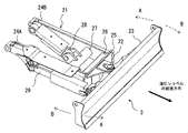
- FIG. FIG. 2 is a perspective view showing the structure of the earth removing device in one embodiment of the present invention, showing a case where the earth removing plate has a predetermined reference attitude.
- 1 is a block diagram showing the configuration of a drive system for driving an angle cylinder in one embodiment of the present invention
- FIG. 4 is a flow chart showing processing contents of a controller relating to standardization of the attitude of the blade in one embodiment of the present invention.
- FIG. 1 is a perspective view showing the structure of the hydraulic excavator in this embodiment.
- FIG. 2 is a perspective view showing the structure of the earth removing device according to this embodiment. vertical position).
- left side upper side in FIG. 1 are simply referred to as the front side, the rear side, the right side, and the left side.
- the hydraulic excavator of this embodiment includes a self-propellable lower traveling body 1 and an upper revolving body 2 provided above the lower traveling body 1 so as to be able to turn. 2 constitutes the vehicle body.
- the hydraulic excavator also includes a soil removal device 3 provided on the front side of the lower traveling body 1 and a working device 5 connected to the front side of the upper revolving body 2 via a swing post 4 .
- the upper revolving body 2 includes a revolving frame 6 forming a basic structure, a cab 7 provided at the front of the revolving frame 6 in which a driver rides, and a counterweight 8 provided at the rear end of the revolving frame 6. , and a machine room 9 provided at the rear of the swing frame 6 (more specifically, between the cab 7 and the counterweight 8).
- the driver's cab 7 has a plurality of units for the operator to instruct the traveling motion of the lower traveling structure 1, the swinging motion of the upper rotating structure 2, the operation of the earth removing device 3, the motion of the swing post 4, and the motion of the working device 5. operating devices, etc. An engine, a hydraulic pump, and the like are arranged in the machine room 9 .
- the swing post 4 is connected to the front side of the revolving frame 6 so as to be rotatable in the left-right direction.
- the extension and contraction drive of the swing cylinder 10 rotates the swing post 4 in the left-right direction, and thus the working device 5 rotates in the left-right direction.
- the work device 5 includes a boom 11 vertically rotatably connected to the swing post 4 , an arm 12 vertically rotatably connected to the boom 11 , and a vertically rotatable arm 12 . and a connected bucket 13 .
- the boom 11, the arm 12, and the bucket 13 are rotated by the telescopic drive of the boom cylinder 14, the arm cylinder 15, and the bucket cylinder 16. As shown in FIG.
- the undercarriage 1 is provided with a track frame 17.
- the track frame 17 is composed of a center frame (not shown), a right side frame 18A provided on the right side of the center frame, and a left side frame 18B provided on the left side of the center frame.
- a driving wheel 19 and a driving motor (not shown) for rotating the driving wheel 19 are provided on the rear end side of the right side frame 18A, and a driven wheel (not shown) is rotatably provided on the front end side,
- a crawler belt (crawler) 20A is wound around the driving wheels and the driven wheels.
- the drive of the right travel motor rotates the right drive wheel 19, which in turn rotates the right crawler belt 20A.
- a drive wheel (not shown) and a drive motor (not shown) for rotating the drive wheel are provided on the rear end side of the left side frame 18B, and a driven wheel (not shown) is provided on the front end side. It is rotatably provided, and a crawler belt (crawler) 20B is wound around the drive wheel and the driven wheel. The drive of the left traveling motor rotates the left drive wheel, and thus the left crawler belt 20B rotates.
- a slewing ring (not shown) is provided on the center frame, and the upper slewing body 2 is rotatably provided through this slewing ring.
- a turning motor (not shown) is driven to turn the upper turning body 2 .
- the earth removing device 3 includes a stay 21 provided on the front side of the center frame of the track frame 17 so as to be vertically rotatable, and a vertically oriented pin shaft 22 at the tip of the stay 21 that is vertically swingable. and a blade plate (blade) 23 provided in the .
- the stay 21 is composed of a pair of support arms 24A, 24B, a removal plate support member 25, a reinforcement beam 26, and a cylinder attachment beam 27.
- the support arms 24A and 24B extend in the front-rear direction, are separated from each other in the left-right direction, and are connected to the front side of the center frame of the track frame 17 so as to be vertically rotatable.
- the unloading plate support member 25 is provided on the tip side of the support arms 24A and 24B, and has a bracket structure consisting of a vertical plate and a pair of horizontal plates provided on the vertical plate with a space therebetween in the vertical direction. And, via the pin shaft 22, the earth removing plate 23 is swingably supported.
- the reinforcing beams 26 are joined to the support arms 24A and 24B and the blade support member 25.
- the cylinder mounting beam 27 is positioned behind the reinforcing beam 26 and joined to the support arms 24A and 24B.
- a lifting cylinder 28 is provided between the cylinder mounting beam 27 and the center frame of the track frame 17 .
- the stay 21 is vertically rotated by the extension/contraction drive of the lifting cylinder 28, and the earth removal plate 23 is lifted/lowered.
- an angle cylinder 29 is provided between the right support arm 24A and the earth removal plate 23.
- the expansion and contraction drive of the angle cylinder 29 swings the earth removal plate 23 forward and backward about the pin shaft 22 .
- FIG. 3 is a diagram showing the configuration of a drive system for driving the angle cylinders in this embodiment.
- the drive system of this embodiment includes a hydraulic pump 31 driven by an engine 30 (prime mover), a control valve 32 for controlling the flow of pressure oil from the hydraulic pump 31 to the angle cylinder 29, and a controller 34 for controlling the control valve 32 according to the instruction of the operation device 33 .
- the operation device 33 includes an operation switch 35A for instructing rocking of one side of the earth removing plate 23 and an operation switch 35B for instructing the rocking of the other side of the earth removing plate 23. As shown in FIG.
- the operation switches 35A and 35B are, for example, push button type.
- the controller 34 outputs a drive signal (extension signal) to the solenoid portion on the left side of the control valve 32 in the drawing when an instruction signal is input from the operation switch 35A.
- a drive signal extension signal
- the control valve 32 is switched to the switching position on the left side in the drawing, and the pressure oil from the hydraulic pump 31 is supplied to the bottom side of the angle cylinder 29 .
- the angle cylinder 29 extends and the earth removal plate 23 swings in the direction of arrow A in FIG.
- the controller 34 outputs a drive signal (contraction signal) to the solenoid portion on the right side of the control valve 32 in the drawing when an instruction signal is input from the operation switch 35B.
- a drive signal contraction signal
- the control valve 32 is switched to the switching position on the right side in the drawing, and pressure oil from the hydraulic pump 31 is supplied to the rod side of the angle cylinder 29 .
- the angle cylinder 29 contracts and the earth removal plate 23 swings in the direction of arrow B in FIG.
- the drive system sets the rocking posture of the blade 23 in the longitudinal direction to a predetermined reference posture (more specifically, the longitudinal direction of the blade 23 is the straight-ahead direction of the hydraulic excavator).
- a reference switch 36 is provided to instruct the controller 34 to assume a vertical orientation.
- the controller 34 controls the control valve 32 in accordance with an instruction from the standardizing switch 36 so that the swing posture of the earth removing plate 23 in the front-rear direction becomes a predetermined standard posture (standardizing the posture of the earth removing plate 23). ).
- the drive system includes pressure sensors 37A and 37B that detect the load pressure of the angle cylinder 29.
- the controller 34 stops controlling the control valve 32 when the load pressure detected by the pressure sensor 37A or 37B is higher than a predetermined threshold when controlling the control valve 32 according to the instruction of the reference switch 36. It's like
- the controller 34 calculates and stores the stroke of the angle cylinder 29 based on the instruction signals from the operation switches 35A and 35B. Further, the reference amount of the stroke of the angle cylinder 29, which is set in advance corresponding to the predetermined reference posture of the earth removing plate 23, is stored.
- the reference switch 36 is, for example, a push button type.
- FIG. 4 is a flow chart showing the processing contents of the controller relating to the standardization of the attitude of the earth removing plate in this embodiment.
- step S1 the controller 34 determines whether or not an instruction signal from the reference switch 36 has been input. If the instruction signal from the reference switch 36 is not input, the determination in step S1 is repeated. On the other hand, when the instruction signal from the reference switch 36 is input, the process proceeds to step S2.
- step S2 the controller 34 determines whether the stroke of the angle cylinder 29 is a predetermined reference amount. Thereby, it is determined whether or not the posture of the ejector plate 23 is a predetermined reference posture. If the stroke of the angle cylinder 29 is not the predetermined reference amount, the process proceeds to step S3.
- step S3 the controller 34 selects the rod side pressure sensor 37A when the stroke of the angle cylinder 29 is smaller than a predetermined reference amount, and selects the bottom side pressure sensor 37A when the stroke of the angle cylinder 29 is greater than the predetermined reference amount.
- a pressure sensor 37B is selected, and it is determined whether or not the load pressure of the angle cylinder 29 detected by the selected pressure sensor is equal to or higher than a predetermined threshold. Thereby, it is determined whether or not the angle cylinder 29 is overloaded.
- the process proceeds to step S4.
- step S4 the controller 34 determines whether the stroke of the angle cylinder 29 is greater than a predetermined reference amount. If the stroke of the angle cylinder 29 is smaller than the predetermined reference amount, the process proceeds to step S5. At step S5, the controller 34 outputs the extension signal described above to switch the control valve 32 to extend the angle cylinder 29. As shown in FIG. On the other hand, when the stroke of the angle cylinder 29 is greater than the predetermined reference amount, the process proceeds to step S6. At step S6, the controller 34 outputs the above-described contraction signal to switch the control valve 32, causing the angle cylinder 29 to contract.
- step S2 After completing step S5 or S6, return to step S2 described above.
- step S2 when the stroke of the angle cylinder 29 is a predetermined reference amount, that is, when the posture of the earth removing plate 23 is a predetermined reference posture, the standardization processing ends. On the other hand, if the stroke of the angle cylinder 29 is not the predetermined reference amount, the process moves to step S3 and repeats the same procedure as described above.
- step S3 if the load pressure of the angle cylinder 29 is equal to or higher than the predetermined threshold, that is, if the angle cylinder 29 is in an overloaded state, the process proceeds to step S7.
- the controller 34 stops controlling the control valve 32 and, for example, sounds the buzzer 38. As shown in FIG.
- the driver can easily return the rocking posture of the earth removing plate 23 to the predetermined standard posture simply by pressing the standardization switch 36 . As a result, working efficiency can be improved.
- the operation switches 35A and 35B and the standardization switch 36 are configured separately, but the configuration is not limited to this.
- the operation switches 35A and 35B may also serve as standardization switches.
- the controller 34 may determine the content of the instruction according to the length of the instruction signal from the operation switch 35A or 35B. That is, the operation switches 35A and 35B instruct rocking of one side and the other side of the earth removal plate 23 by short pressing, respectively, and at least one of the operation switches 35A and 35B is pressed long.
- the controller 34 may be instructed to set the rocking posture of the earth removing plate 23 to a predetermined reference posture by an operation.
- the operation device 33 has been described as an example in which the push-button operation switches 35A and 35B are used, but the present invention is not limited to this.
- the operation device 33 may be composed of, for example, a toggle type operation switch.
- the earth removal device 3 is provided with the earth removal plate 23 at the tip of the stay 21 through the vertical pin shaft 22 so as to be swingable only in the front-rear direction.
- the angle cylinder 29 is provided for swinging in the direction has been described as an example, it is not limited to this.
- a free pin specifically, a pin shaft rotatably supported at the tip of the stay in the front-rear direction and a pin hole in a direction orthogonal to this
- a rotating pin specifically, a is passed through the pin hole of the free pin and supports the blade so that it can swing in the front-back direction
- An angle cylinder for swinging in the longitudinal direction and a tilt cylinder for swinging the earth removing plate in the vertical direction may be provided.
Abstract
Description
2 上部旋回体
21 ステー
23 排土板
29 アングルシリンダ
31 油圧ポンプ
32 制御弁
33 操作装置
34 コントローラ
35A,35B 操作スイッチ
36 基準化スイッチ
37A,37B 圧力センサ
Claims (3)
- 車体に上下方向に回動可能に設けられたステーと、前記ステーの先端部に前後方向に揺動可能に設けられた排土板と、前記排土板を前後方向に揺動させるアングルシリンダと、油圧ポンプから前記アングルシリンダへの圧油の流れを制御する制御弁と、前記排土板の前後方向の揺動動作を指示する操作装置と、前記操作装置の指示に応じて前記制御弁を制御するコントローラとを備えた建設機械であって、
前記排土板の前後方向に対する揺動姿勢を所定の基準姿勢にすることを前記コントローラに指示する基準化スイッチを備え、
前記コントローラは、前記基準化スイッチの指示に応じて、前記排土板の前後方向に対する揺動姿勢が所定の基準姿勢となるように前記制御弁を制御することを特徴とする建設機械。 - 請求項1に記載の建設機械において、
前記アングルシリンダの負荷圧を検出する圧力センサを備え、
前記コントローラは、前記基準化スイッチの指示に応じて前記制御弁を制御する際に、前記圧力センサで検出された負荷圧が所定の閾値より高い場合は、前記制御弁の制御を停止することを特徴とする建設機械。 - 請求項1に記載の建設機械において、
前記操作装置は、短押し操作によって前記排土板の一方側の揺動を指示する押しボタン式の第1操作スイッチと、短押し操作によって前記排土板の他方側の揺動を指示する押しボタン式の第2操作スイッチとで構成されており、
前記第1操作スイッチ及び前記第2操作スイッチのうちの少なくともいずれか一方は、前記基準化スイッチを兼用し、長押し操作によって前記排土板の揺動姿勢を所定の基準姿勢にすることを前記コントローラに指示することを特徴とする建設機械。
Priority Applications (4)
| Application Number | Priority Date | Filing Date | Title |
|---|---|---|---|
| US18/039,585 US20240093463A1 (en) | 2021-03-11 | 2022-01-18 | Construction machine |
| KR1020237021518A KR20230110610A (ko) | 2021-03-11 | 2022-01-18 | 건설 기계 |
| CN202280008039.0A CN116635593A (zh) | 2021-03-11 | 2022-01-18 | 工程机械 |
| EP22766618.7A EP4234818A1 (en) | 2021-03-11 | 2022-01-18 | Construction machine |
Applications Claiming Priority (2)
| Application Number | Priority Date | Filing Date | Title |
|---|---|---|---|
| JP2021-039743 | 2021-03-11 | ||
| JP2021039743A JP7096388B1 (ja) | 2021-03-11 | 2021-03-11 | 建設機械 |
Publications (1)
| Publication Number | Publication Date |
|---|---|
| WO2022190650A1 true WO2022190650A1 (ja) | 2022-09-15 |
Family
ID=82308090
Family Applications (1)
| Application Number | Title | Priority Date | Filing Date |
|---|---|---|---|
| PCT/JP2022/001670 WO2022190650A1 (ja) | 2021-03-11 | 2022-01-18 | 建設機械 |
Country Status (6)
| Country | Link |
|---|---|
| US (1) | US20240093463A1 (ja) |
| EP (1) | EP4234818A1 (ja) |
| JP (1) | JP7096388B1 (ja) |
| KR (1) | KR20230110610A (ja) |
| CN (1) | CN116635593A (ja) |
| WO (1) | WO2022190650A1 (ja) |
Families Citing this family (1)
| Publication number | Priority date | Publication date | Assignee | Title |
|---|---|---|---|---|
| DE202023106779U1 (de) | 2023-08-23 | 2024-01-11 | Hyundai Mobis Co., Ltd. | Luftauslass für Fahrzeug |
Citations (10)
| Publication number | Priority date | Publication date | Assignee | Title |
|---|---|---|---|---|
| JPH073836A (ja) * | 1993-06-11 | 1995-01-06 | Komatsu Ltd | ブルドーザの作業機コントロール装置 |
| JPH10259618A (ja) * | 1997-03-18 | 1998-09-29 | Shin Caterpillar Mitsubishi Ltd | 建設機械の制御装置 |
| JPH11280118A (ja) * | 1998-03-30 | 1999-10-12 | Shin Caterpillar Mitsubishi Ltd | 小型油圧ショベル |
| JP2010126932A (ja) * | 2008-11-26 | 2010-06-10 | Komatsu Ltd | 作業車両の作業機操作装置 |
| JP2011014104A (ja) * | 2009-07-06 | 2011-01-20 | Sumitomo (Shi) Construction Machinery Co Ltd | 建設機械の操作レバースイッチ装置 |
| JP2012072636A (ja) * | 2010-09-30 | 2012-04-12 | Hitachi Constr Mach Co Ltd | 油圧ショベルの操作システム |
| JP2013181274A (ja) | 2012-02-29 | 2013-09-12 | Hitachi Constr Mach Co Ltd | 建設機械の排土装置 |
| JP2014031696A (ja) * | 2012-08-06 | 2014-02-20 | Komatsu Ltd | 作業機械及び作業機械のブレードの自動制御方法 |
| JP2019167686A (ja) * | 2018-03-22 | 2019-10-03 | 株式会社日立建機ティエラ | 建設機械 |
| JP2020084460A (ja) * | 2018-11-19 | 2020-06-04 | 株式会社小松製作所 | 作業機を含む作業機械を自動制御するためのシステム及び方法 |
-
2021
- 2021-03-11 JP JP2021039743A patent/JP7096388B1/ja active Active
-
2022
- 2022-01-18 US US18/039,585 patent/US20240093463A1/en active Pending
- 2022-01-18 WO PCT/JP2022/001670 patent/WO2022190650A1/ja active Application Filing
- 2022-01-18 CN CN202280008039.0A patent/CN116635593A/zh active Pending
- 2022-01-18 EP EP22766618.7A patent/EP4234818A1/en active Pending
- 2022-01-18 KR KR1020237021518A patent/KR20230110610A/ko unknown
Patent Citations (10)
| Publication number | Priority date | Publication date | Assignee | Title |
|---|---|---|---|---|
| JPH073836A (ja) * | 1993-06-11 | 1995-01-06 | Komatsu Ltd | ブルドーザの作業機コントロール装置 |
| JPH10259618A (ja) * | 1997-03-18 | 1998-09-29 | Shin Caterpillar Mitsubishi Ltd | 建設機械の制御装置 |
| JPH11280118A (ja) * | 1998-03-30 | 1999-10-12 | Shin Caterpillar Mitsubishi Ltd | 小型油圧ショベル |
| JP2010126932A (ja) * | 2008-11-26 | 2010-06-10 | Komatsu Ltd | 作業車両の作業機操作装置 |
| JP2011014104A (ja) * | 2009-07-06 | 2011-01-20 | Sumitomo (Shi) Construction Machinery Co Ltd | 建設機械の操作レバースイッチ装置 |
| JP2012072636A (ja) * | 2010-09-30 | 2012-04-12 | Hitachi Constr Mach Co Ltd | 油圧ショベルの操作システム |
| JP2013181274A (ja) | 2012-02-29 | 2013-09-12 | Hitachi Constr Mach Co Ltd | 建設機械の排土装置 |
| JP2014031696A (ja) * | 2012-08-06 | 2014-02-20 | Komatsu Ltd | 作業機械及び作業機械のブレードの自動制御方法 |
| JP2019167686A (ja) * | 2018-03-22 | 2019-10-03 | 株式会社日立建機ティエラ | 建設機械 |
| JP2020084460A (ja) * | 2018-11-19 | 2020-06-04 | 株式会社小松製作所 | 作業機を含む作業機械を自動制御するためのシステム及び方法 |
Also Published As
| Publication number | Publication date |
|---|---|
| JP7096388B1 (ja) | 2022-07-05 |
| CN116635593A (zh) | 2023-08-22 |
| JP2022139384A (ja) | 2022-09-26 |
| KR20230110610A (ko) | 2023-07-24 |
| US20240093463A1 (en) | 2024-03-21 |
| EP4234818A1 (en) | 2023-08-30 |
Similar Documents
| Publication | Publication Date | Title |
|---|---|---|
| US10246855B2 (en) | Material handling machine with bucket shake control system and method | |
| JP2000096601A (ja) | 作業機の角度制御方法及びその制御装置 | |
| US7637039B2 (en) | Method and apparatus for controlling hydraulic pump for working machine of working vehicle | |
| JP6625575B2 (ja) | 建設機械 | |
| CN108699803B (zh) | 机动平路机的控制方法以及机动平路机 | |
| WO2022190650A1 (ja) | 建設機械 | |
| WO2019082600A1 (ja) | 作業車両 | |
| CN114174598B (zh) | 建筑机械 | |
| EP3719217B1 (en) | A control method for actuating a return-to-dig movement of an implement, such as a bucket, in a work vehicle, a corresponding control system and a work vehicle comprising such control system | |
| CN114207223A (zh) | 控制系统、作业车辆的控制方法以及作业车辆 | |
| CN111287232A (zh) | 用于作业机械的改进的作业机具附接件 | |
| WO2021193321A1 (ja) | 作業機械および作業機械の制御方法 | |
| JP3853208B2 (ja) | 作業車両の作業機用油圧ポンプの制御方法と制御装置 | |
| US20220136203A1 (en) | Coordinated actuator control by an operator control | |
| JP7042781B2 (ja) | 作業車両 | |
| JPH0771057A (ja) | バックホウ | |
| JPH089234Y2 (ja) | 持上げ運搬作業機 | |
| JP3922701B2 (ja) | 作業車両の作業機用油圧ポンプの制御方法と制御装置 | |
| JP3461281B2 (ja) | 建設機械の作業機制御装置 | |
| JP4183722B2 (ja) | 作業車両の作業機用油圧ポンプの制御装置 | |
| JP4227936B2 (ja) | ホイール式建設機械 | |
| JPH08259195A (ja) | フォークリフトの作業装置 | |
| WO2023067943A1 (ja) | 作業機械の制御システムおよび制御方法 | |
| JP7264557B1 (ja) | 昇降式クローラ作業車両 | |
| JP2019172383A (ja) | 建設機械 |
Legal Events
| Date | Code | Title | Description |
|---|---|---|---|
| 121 | Ep: the epo has been informed by wipo that ep was designated in this application |
Ref document number: 22766618 Country of ref document: EP Kind code of ref document: A1 |
|
| ENP | Entry into the national phase |
Ref document number: 2022766618 Country of ref document: EP Effective date: 20230524 |
|
| WWE | Wipo information: entry into national phase |
Ref document number: 18039585 Country of ref document: US |
|
| WWE | Wipo information: entry into national phase |
Ref document number: 202280008039.0 Country of ref document: CN |
|
| ENP | Entry into the national phase |
Ref document number: 20237021518 Country of ref document: KR Kind code of ref document: A |
|
| NENP | Non-entry into the national phase |
Ref country code: DE |