WO2022176288A1 - 天井搬送車 - Google Patents
天井搬送車 Download PDFInfo
- Publication number
- WO2022176288A1 WO2022176288A1 PCT/JP2021/042080 JP2021042080W WO2022176288A1 WO 2022176288 A1 WO2022176288 A1 WO 2022176288A1 JP 2021042080 W JP2021042080 W JP 2021042080W WO 2022176288 A1 WO2022176288 A1 WO 2022176288A1
- Authority
- WO
- WIPO (PCT)
- Prior art keywords
- holding unit
- stereo camera
- overhead
- unit
- transport vehicle
- Prior art date
- Legal status (The legal status is an assumption and is not a legal conclusion. Google has not performed a legal analysis and makes no representation as to the accuracy of the status listed.)
- Ceased
Links
Images


Classifications
-
- H—ELECTRICITY
- H10—SEMICONDUCTOR DEVICES; ELECTRIC SOLID-STATE DEVICES NOT OTHERWISE PROVIDED FOR
- H10P—GENERIC PROCESSES OR APPARATUS FOR THE MANUFACTURE OR TREATMENT OF DEVICES COVERED BY CLASS H10
- H10P72/00—Handling or holding of wafers, substrates or devices during manufacture or treatment thereof
- H10P72/50—Handling or holding of wafers, substrates or devices during manufacture or treatment thereof for positioning, orientation or alignment
- H10P72/53—Handling or holding of wafers, substrates or devices during manufacture or treatment thereof for positioning, orientation or alignment using optical controlling means
-
- B—PERFORMING OPERATIONS; TRANSPORTING
- B65—CONVEYING; PACKING; STORING; HANDLING THIN OR FILAMENTARY MATERIAL
- B65G—TRANSPORT OR STORAGE DEVICES, e.g. CONVEYORS FOR LOADING OR TIPPING, SHOP CONVEYOR SYSTEMS OR PNEUMATIC TUBE CONVEYORS
- B65G1/00—Storing articles, individually or in orderly arrangement, in warehouses or magazines
-
- H—ELECTRICITY
- H10—SEMICONDUCTOR DEVICES; ELECTRIC SOLID-STATE DEVICES NOT OTHERWISE PROVIDED FOR
- H10P—GENERIC PROCESSES OR APPARATUS FOR THE MANUFACTURE OR TREATMENT OF DEVICES COVERED BY CLASS H10
- H10P72/00—Handling or holding of wafers, substrates or devices during manufacture or treatment thereof
- H10P72/06—Apparatus for monitoring, sorting, marking, testing or measuring
- H10P72/0606—Position monitoring, e.g. misposition detection or presence detection
-
- B—PERFORMING OPERATIONS; TRANSPORTING
- B65—CONVEYING; PACKING; STORING; HANDLING THIN OR FILAMENTARY MATERIAL
- B65G—TRANSPORT OR STORAGE DEVICES, e.g. CONVEYORS FOR LOADING OR TIPPING, SHOP CONVEYOR SYSTEMS OR PNEUMATIC TUBE CONVEYORS
- B65G1/00—Storing articles, individually or in orderly arrangement, in warehouses or magazines
- B65G1/02—Storage devices
- B65G1/04—Storage devices mechanical
-
- B—PERFORMING OPERATIONS; TRANSPORTING
- B65—CONVEYING; PACKING; STORING; HANDLING THIN OR FILAMENTARY MATERIAL
- B65G—TRANSPORT OR STORAGE DEVICES, e.g. CONVEYORS FOR LOADING OR TIPPING, SHOP CONVEYOR SYSTEMS OR PNEUMATIC TUBE CONVEYORS
- B65G1/00—Storing articles, individually or in orderly arrangement, in warehouses or magazines
- B65G1/02—Storage devices
- B65G1/04—Storage devices mechanical
- B65G1/0457—Storage devices mechanical with suspended load carriers
-
- B—PERFORMING OPERATIONS; TRANSPORTING
- B65—CONVEYING; PACKING; STORING; HANDLING THIN OR FILAMENTARY MATERIAL
- B65G—TRANSPORT OR STORAGE DEVICES, e.g. CONVEYORS FOR LOADING OR TIPPING, SHOP CONVEYOR SYSTEMS OR PNEUMATIC TUBE CONVEYORS
- B65G1/00—Storing articles, individually or in orderly arrangement, in warehouses or magazines
- B65G1/02—Storage devices
- B65G1/04—Storage devices mechanical
- B65G1/137—Storage devices mechanical with arrangements or automatic control means for selecting which articles are to be removed
- B65G1/1373—Storage devices mechanical with arrangements or automatic control means for selecting which articles are to be removed for fulfilling orders in warehouses
- B65G1/1375—Storage devices mechanical with arrangements or automatic control means for selecting which articles are to be removed for fulfilling orders in warehouses the orders being assembled on a commissioning stacker-crane or truck
-
- B—PERFORMING OPERATIONS; TRANSPORTING
- B65—CONVEYING; PACKING; STORING; HANDLING THIN OR FILAMENTARY MATERIAL
- B65G—TRANSPORT OR STORAGE DEVICES, e.g. CONVEYORS FOR LOADING OR TIPPING, SHOP CONVEYOR SYSTEMS OR PNEUMATIC TUBE CONVEYORS
- B65G35/00—Mechanical conveyors not otherwise provided for
- B65G35/06—Mechanical conveyors not otherwise provided for comprising a load-carrier moving along a path, e.g. a closed path, and adapted to be engaged by any one of a series of traction elements spaced along the path
-
- B—PERFORMING OPERATIONS; TRANSPORTING
- B66—HOISTING; LIFTING; HAULING
- B66C—CRANES; LOAD-ENGAGING ELEMENTS OR DEVICES FOR CRANES, CAPSTANS, WINCHES, OR TACKLES
- B66C13/00—Other constructional features or details
- B66C13/18—Control systems or devices
- B66C13/46—Position indicators for suspended loads or for crane elements
-
- B—PERFORMING OPERATIONS; TRANSPORTING
- B66—HOISTING; LIFTING; HAULING
- B66C—CRANES; LOAD-ENGAGING ELEMENTS OR DEVICES FOR CRANES, CAPSTANS, WINCHES, OR TACKLES
- B66C13/00—Other constructional features or details
- B66C13/18—Control systems or devices
- B66C13/48—Automatic control of crane drives for producing a single or repeated working cycle; Program control
-
- B—PERFORMING OPERATIONS; TRANSPORTING
- B66—HOISTING; LIFTING; HAULING
- B66C—CRANES; LOAD-ENGAGING ELEMENTS OR DEVICES FOR CRANES, CAPSTANS, WINCHES, OR TACKLES
- B66C19/00—Cranes comprising trolleys or crabs running on fixed or movable bridges or gantries
-
- G—PHYSICS
- G01—MEASURING; TESTING
- G01B—MEASURING LENGTH, THICKNESS OR SIMILAR LINEAR DIMENSIONS; MEASURING ANGLES; MEASURING AREAS; MEASURING IRREGULARITIES OF SURFACES OR CONTOURS
- G01B11/00—Measuring arrangements characterised by the use of optical techniques
- G01B11/02—Measuring arrangements characterised by the use of optical techniques for measuring length, width or thickness
- G01B11/026—Measuring arrangements characterised by the use of optical techniques for measuring length, width or thickness by measuring distance between sensor and object
-
- H—ELECTRICITY
- H04—ELECTRIC COMMUNICATION TECHNIQUE
- H04N—PICTORIAL COMMUNICATION, e.g. TELEVISION
- H04N23/00—Cameras or camera modules comprising electronic image sensors; Control thereof
- H04N23/90—Arrangement of cameras or camera modules, e.g. multiple cameras in TV studios or sports stadiums
-
- H—ELECTRICITY
- H10—SEMICONDUCTOR DEVICES; ELECTRIC SOLID-STATE DEVICES NOT OTHERWISE PROVIDED FOR
- H10P—GENERIC PROCESSES OR APPARATUS FOR THE MANUFACTURE OR TREATMENT OF DEVICES COVERED BY CLASS H10
- H10P72/00—Handling or holding of wafers, substrates or devices during manufacture or treatment thereof
- H10P72/06—Apparatus for monitoring, sorting, marking, testing or measuring
- H10P72/0618—Apparatus for monitoring, sorting, marking, testing or measuring using identification means, e.g. labels on substrates or labels on containers
-
- H—ELECTRICITY
- H10—SEMICONDUCTOR DEVICES; ELECTRIC SOLID-STATE DEVICES NOT OTHERWISE PROVIDED FOR
- H10P—GENERIC PROCESSES OR APPARATUS FOR THE MANUFACTURE OR TREATMENT OF DEVICES COVERED BY CLASS H10
- H10P72/00—Handling or holding of wafers, substrates or devices during manufacture or treatment thereof
- H10P72/30—Handling or holding of wafers, substrates or devices during manufacture or treatment thereof for conveying, e.g. between different workstations
- H10P72/32—Handling or holding of wafers, substrates or devices during manufacture or treatment thereof for conveying, e.g. between different workstations between different workstations
- H10P72/3206—Handling or holding of wafers, substrates or devices during manufacture or treatment thereof for conveying, e.g. between different workstations between different workstations the substrate being handled substantially vertically
-
- H—ELECTRICITY
- H10—SEMICONDUCTOR DEVICES; ELECTRIC SOLID-STATE DEVICES NOT OTHERWISE PROVIDED FOR
- H10P—GENERIC PROCESSES OR APPARATUS FOR THE MANUFACTURE OR TREATMENT OF DEVICES COVERED BY CLASS H10
- H10P72/00—Handling or holding of wafers, substrates or devices during manufacture or treatment thereof
- H10P72/30—Handling or holding of wafers, substrates or devices during manufacture or treatment thereof for conveying, e.g. between different workstations
- H10P72/32—Handling or holding of wafers, substrates or devices during manufacture or treatment thereof for conveying, e.g. between different workstations between different workstations
- H10P72/3218—Conveying cassettes, containers or carriers
-
- H—ELECTRICITY
- H10—SEMICONDUCTOR DEVICES; ELECTRIC SOLID-STATE DEVICES NOT OTHERWISE PROVIDED FOR
- H10P—GENERIC PROCESSES OR APPARATUS FOR THE MANUFACTURE OR TREATMENT OF DEVICES COVERED BY CLASS H10
- H10P72/00—Handling or holding of wafers, substrates or devices during manufacture or treatment thereof
- H10P72/30—Handling or holding of wafers, substrates or devices during manufacture or treatment thereof for conveying, e.g. between different workstations
- H10P72/32—Handling or holding of wafers, substrates or devices during manufacture or treatment thereof for conveying, e.g. between different workstations between different workstations
- H10P72/3221—Overhead conveying
-
- B—PERFORMING OPERATIONS; TRANSPORTING
- B65—CONVEYING; PACKING; STORING; HANDLING THIN OR FILAMENTARY MATERIAL
- B65G—TRANSPORT OR STORAGE DEVICES, e.g. CONVEYORS FOR LOADING OR TIPPING, SHOP CONVEYOR SYSTEMS OR PNEUMATIC TUBE CONVEYORS
- B65G2201/00—Indexing codes relating to handling devices, e.g. conveyors, characterised by the type of product or load being conveyed or handled
- B65G2201/02—Articles
- B65G2201/0297—Wafer cassette
-
- B—PERFORMING OPERATIONS; TRANSPORTING
- B65—CONVEYING; PACKING; STORING; HANDLING THIN OR FILAMENTARY MATERIAL
- B65G—TRANSPORT OR STORAGE DEVICES, e.g. CONVEYORS FOR LOADING OR TIPPING, SHOP CONVEYOR SYSTEMS OR PNEUMATIC TUBE CONVEYORS
- B65G2203/00—Indexing code relating to control or detection of the articles or the load carriers during conveying
- B65G2203/04—Detection means
- B65G2203/041—Camera
-
- B—PERFORMING OPERATIONS; TRANSPORTING
- B65—CONVEYING; PACKING; STORING; HANDLING THIN OR FILAMENTARY MATERIAL
- B65G—TRANSPORT OR STORAGE DEVICES, e.g. CONVEYORS FOR LOADING OR TIPPING, SHOP CONVEYOR SYSTEMS OR PNEUMATIC TUBE CONVEYORS
- B65G2203/00—Indexing code relating to control or detection of the articles or the load carriers during conveying
- B65G2203/04—Detection means
- B65G2203/042—Sensors
Definitions
- One aspect of the present invention relates to an overhead transport vehicle.
- the carrier described in Patent Document 1 is known as a technology related to the overhead carrier.
- the transport vehicle described in Patent Document 1 includes a main body, an elevator (holding unit) having a holding portion for holding an article, and a flexible suspension member that is extended and wound to move the elevator up and down.
- An elevation driving unit and a look-down sensor provided in the elevation driving unit for irradiating detection waves having directivity such as laser light are provided.
- detection waves are emitted from the look-down sensor toward the vicinity of the descent destination of the platform to determine the presence or absence of a foreign object (obstacle).
- An overhead transport vehicle is provided to be able to move up and down, and includes a holding unit that holds an article, and a three-dimensional measuring range that includes, in a detection range, the periphery of a lower space formed directly below the article held by the holding unit.
- a distance sensor and a control device that determines the presence or absence of an obstacle based on the detection result of the three-dimensional distance measurement sensor.
- the three-dimensional distance measuring sensor can detect objects in a wider detection range than lookdown sensors.
- the three-dimensional ranging sensor can detect objects existing in the detection range in three dimensions, it is possible to suppress erroneous judgments such as protruding parts such as peripheral devices at high positions as obstacles. It becomes possible. Therefore, it is possible to accurately and reliably determine the presence or absence of an obstacle.
- the three-dimensional ranging sensor includes at least one of the holding unit and the article held by the holding unit in its detection range, and the control device detects the detection result of the three-dimensional ranging sensor. Based on this, at least one of shaking, tilting, and rotating of the article held by the holding unit may be determined. In this case, when the article is transferred, for example, the determination result of at least one of shaking, tilting and rotation of the article can be used to control the lifting and lowering of the holding unit. etc. can be prevented.
- At least one of the holding unit and the article held by the holding unit may have a light emitter, and the three-dimensional distance measuring sensor may detect light emission from the light emitter. This makes it possible to determine at least one of shaking, tilting, and rotation of the article using light emitted from the light emitter.
- At least one of the holding unit and the article held by the holding unit may have an AR marker, and the three-dimensional ranging sensor may detect the AR marker. This makes it possible to determine at least one of swing, tilt and rotation of the article using the AR marker.
- the three-dimensional ranging sensor may include a stereo camera.
- the stereo camera does not interfere with the other infrared sensors, etc. It is possible to suppress the adverse effect of the sensor.
- the stereo camera may be provided at a position above the holding unit so as to be able to overlook the holding unit, and may include the holding unit at the lowest point in the angle of view.
- a stereo camera can be effectively used as a three-dimensional ranging sensor.
- An overhead transport vehicle includes a lifting drive unit that lifts and lowers the holding unit, and the three-dimensional distance measuring sensor is arranged in the lifting drive unit at a position directly above the article held by the holding unit. good.
- the three-dimensional distance measuring sensor is arranged in the lifting drive unit at a position directly above the article held by the holding unit. good.
- An overhead guided vehicle may include a gyro sensor and an acceleration sensor that detect the shake and tilt of the three-dimensional ranging sensor. In this case, it is possible to determine the presence or absence of an obstacle more accurately and reliably.
- an overhead guided vehicle capable of accurately and reliably determining the presence or absence of an obstacle.
- FIG. 1 is a side view showing an overhead transport vehicle according to one embodiment.
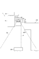
- FIG. 2 is a front view showing a detection range of a stereo camera in the ceiling transport vehicle of FIG. 1;
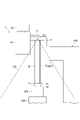
- FIG. 2 is a front view showing a detection range of a stereo camera in the ceiling transport vehicle of FIG. 1;
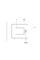
- FIG. 4 is a diagram showing an image including light emitters according to a modification.
- FIG. 5 is a diagram showing an image including AR markers according to a modification.
- the ceiling transport vehicle 1 of one embodiment travels along a track 20 laid near the ceiling of a clean room where semiconductor devices are manufactured.
- the overhead transport vehicle 1 transports a FOUP (Front Opening Unified Pod) (goods) 200 containing a plurality of semiconductor wafers, and a load port (transfer unit) provided in a processing apparatus that performs various processes on semiconductor wafers.
- FOUP 200 is transferred to 300 and the like.
- the overhead carrier 1 includes a frame unit 2 , a traveling unit 3 , a lateral unit 4 , a sheeter unit 5 , an elevation drive unit 6 , a holding unit 7 , a carrier controller (control unit) 8 , and a communication unit 9 . And prepare.
- the frame unit 2 has a center frame 15 , a front frame 16 and a rear frame 17 .
- the front frame 16 extends downward from the front end of the center frame 15 (the front side in the running direction of the overhead transport vehicle 1).
- the rear frame 17 extends downward from the rear end of the center frame 15 (the rear side in the running direction of the overhead transport vehicle 1).
- the traveling unit 3 is arranged above the center frame 15 .
- the traveling unit 3 travels along the track 20 by being supplied with electric power in a non-contact manner from, for example, a high-frequency current line laid along the track 20 .
- the lateral unit 4 is arranged below the center frame 15 .
- the lateral unit 4 moves the sheeter unit 5, the lifting drive unit 6, and the holding unit 7 in the lateral direction (sideways in the traveling direction of the overhead transport vehicle 1).
- the theta unit 5 is arranged below the lateral unit 4 .
- the sheeter unit 5 rotates the elevation drive unit 6 and the holding unit 7 in the horizontal plane.
- the elevation drive unit 6 is arranged below the sheeter unit 5 .
- the elevation drive unit 6 raises and lowers the holding unit 7 .
- the elevation drive unit 6 raises and lowers the holding unit 7 by winding or unwinding the belt B connected to the holding unit 7 .
- the holding unit 7 is provided so as to be able to move up and down.
- the holding unit 7 is arranged below the elevation drive unit 6 .
- the holding unit 7 is suspended by a plurality of belts B.
- the holding unit 7 moves up and down as the belt B is wound up or drawn out by the up-and-down drive unit 6 .
- the holding unit 7 holds (grips) the flange 201 of the FOUP 200 .
- the holding unit 7 has a pair of grippers 12,12. A pair of grippers 12, 12 are opened and closed by, for example, a drive motor and a link mechanism.
- the transport vehicle controller 8 is arranged on the center frame 15, for example.
- the transport vehicle controller 8 is an electronic control unit composed of a CPU (Central Processing Unit), a ROM (Read only memory), a RAM (Random access memory), and the like.
- the transport vehicle controller 8 controls each part of the overhead transport vehicle 1 .
- the ceiling guided vehicle 1 configured as described above operates as follows.
- the overhead transport vehicle 1 that does not hold the FOUP 200 is stopped at a position corresponding to the load port 300 .
- the horizontal position and horizontal angle of the holding unit 7 are adjusted by driving the lateral unit 4 and the theta unit 5.
- the lifting unit 6 lowers the holding unit 7 to hold the flange 201 of the FOUP 200 placed on the load port 300 .
- the lifting drive unit 6 raises the holding unit 7 to the highest position.
- the overhead carrier 1 holding the FOUP 200 is stopped at a position corresponding to the load port 300 .
- the lateral unit 4 and the theta unit 5 are driven to adjust the horizontal position and horizontal angle of the holding unit.
- the holding unit 7 is lowered by the elevation drive unit 6, the FOUP 200 is placed on the load port 300, and the holding of the flange 201 by the holding unit 7 is released.
- the lifting drive unit 6 raises the holding unit 7 to the highest position.
- the ceiling guided vehicle 1 of this embodiment includes a light emitter 7K and a stereo camera SC.
- the light emitter 7K is provided in the holding unit 7. As shown in FIG.
- the light emitter 7K is arranged at a position within the angle of view of the stereo camera SC.
- the light emitter 7K is provided above the holding unit 7. As shown in FIG.
- the light emitter 7K emits a straight laser beam upward.
- the light emitter 7K emits infrared rays.
- an infrared LED is used as the light emitter 7K.
- the position where the light emitter 7K is provided is not particularly limited as long as it is within the detection range of the stereo camera SC.
- the stereo camera SC is a device capable of recognizing an object within its detection range and acquiring information on the distance to that object by using multiple cameras to shoot from multiple different directions at the same time.
- a passive stereo camera that captures ambient light is used.
- Stereo camera SC constitutes a three-dimensional ranging sensor.
- object recognition various known image recognition techniques and image processing techniques can be used.
- the object distance information in this embodiment corresponds to the object height information.
- the stereo camera SC is provided at a position above the holding unit 7 so as to be able to overlook the holding unit 7 .
- the stereo camera SC is arranged at a position directly above the FOUP 200 held by the holding unit 7 in the elevation drive unit 6 .
- the stereo camera SC is provided in the central portion of the elevation drive unit 6 facing downward.
- the detection range DA includes at least the holding unit 7, the FOUP 200 held by the holding unit 7, and the surroundings of the lower space R formed immediately below the FOUP 200 held by the holding unit 7.
- the lower space R forms a three-dimensional route for unloading the FOUP 200 onto the load port 300 .
- the lower space R constitutes an elevating path for the FOUP 200 when the holding unit 7 is moved up and down to transfer the FOUP 200 .
- the stereo camera SC can capture an image of the surroundings of the load port 300 in a bird's-eye view.
- the stereo camera SC includes the holding unit 7 at the lowest position (the holding unit 7 at the height position holding the FOUP 200 placed on the load port 300) in the angle of view.
- the stereo camera SC can detect light emission (infrared rays) from the light emitter 7K.
- the transport vehicle controller 8 determines the presence or absence of an obstacle based on the detection result of the stereo camera SC. Obstacles include, for example, people around the load port 300, hanging rods, stepladder top plates, rolling towers, and the like. As an example, the transport vehicle controller 8, based on the object recognized by the stereo camera SC and its distance information, determines that the object interferes with the lower space R or is likely to interfere with the object. is determined as an obstacle. Various known determination methods can be used to determine whether an object is interfering with the lower space R (whether there is a high possibility of such interference).
- the transport vehicle controller 8 determines shaking, tilting, and rotation of the FOUP 200 held by the holding unit 7 based on the detection results of the stereo camera SC. As an example, the transport vehicle controller 8 determines whether or not the FOUP 200 is shaking by a predetermined amount or more and the shaking speed from the light emission behavior of the light emitter 7K detected by the stereo camera SC. Shaking of the FOUP 200 can be determined based on how much the laser beam emitted from the light emitter 7K deviates from the target axis. Further, as an example, the transport vehicle controller 8 determines whether or not the FOUP 200 is tilted by a predetermined amount or more based on the light emission position of the light emitter 7K detected by the stereo camera SC. As an example, the transport vehicle controller 8 determines whether or not the FOUP 200 is rotated about the vertical axis by a predetermined amount or more based on the light emission position of the light emitter 7K detected by the stereo camera SC.
- the transport vehicle controller 8 transmits determination result information regarding the presence or absence of obstacles to a host controller (not shown) or the like.
- the host controller notifies the operator of determination result information regarding the presence or absence of an obstacle.
- the transport vehicle controller 8 stops or prohibits the lifting of the holding unit 7 .
- the transport vehicle controller 8 controls the transfer operation of the FOUP 200 based on the determination result information regarding the swing, tilt and rotation of the FOUP 200 held by the holding unit 7 . For example, the transport vehicle controller 8 moves up and down the holding unit 7, drives the lateral unit 4, and rotates the sheeter unit so that the shaking of the FOUP 200 is reduced, the inclination of the FOUP 200 is reduced, and the rotation of the FOUP 200 is reduced.
- At least one of 5 drives is controlled. If any one of the swing, tilt, and rotation of the FOUP 200 held by the holding unit 7 exceeds a predetermined amount, the transport vehicle controller 8 stops or prohibits the lifting and lowering of the holding unit 7, and the host controller , sway, tilt and rotation error information to the operator.
- the stereo camera SC can detect an object in a wider detection range DA than a lookdown sensor or the like. With the stereo camera SC, range detection can be performed in a plane. In addition, since the stereo camera SC can three-dimensionally detect an object existing in the detection range, for example, the projecting portion 400T (see FIGS. 2 and 3) of the peripheral device 400 or the like at a high position may be used as an obstacle. erroneous determination can be suppressed. Therefore, according to the ceiling guided vehicle 1, it is possible to accurately and reliably determine the presence or absence of an obstacle.
- the stereo camera SC includes the holding unit 7 and the FOUP 200 held by the holding unit 7 in its detection range.
- the transport vehicle controller 8 determines shaking, tilting, and rotation of the FOUP 200 held by the holding unit 7 based on the detection result of the stereo camera SC. In this case, it is possible to widen the range and improve the accuracy of detection of shaking, tilting, and rotation of the FOUP 200 .
- the FOUP 200 is transferred, it is possible to control the lifting and lowering of the holding unit 7 by using the determination result of the shaking, tilting, and rotation of the FOUP 200, thereby preventing mistakes in transferring the FOUP 200. becomes.
- the holding unit 7 has a light emitter 7K, and the stereo camera SC detects the light emission of this light emitter 7K. As a result, it is possible to determine the shake, tilt, and rotation of the FOUP 200 using the light emitted from the light emitter 7K.
- the ceiling transport vehicle 1 uses a stereo camera SC as a three-dimensional ranging sensor.
- the stereo camera SC does not interfere with the other infrared sensors or the like. It is possible to suppress the adverse effects of SC.
- the stereo camera SC as a three-dimensional ranging sensor, it is possible to determine the presence or absence of an obstacle without being affected by other infrared sensors in the surroundings.
- the stereo camera SC as a three-dimensional ranging sensor, it becomes possible to easily recognize obstacles.
- the stereo camera SC is provided at a position above the holding unit 7 so that the holding unit 7 can be viewed from above, and the angle of view includes the holding unit 7 at the lowest point.
- the stereo camera SC can be effectively used as a three-dimensional ranging sensor.
- the ceiling transport vehicle 1 includes an elevation drive unit 6 that raises and lowers the holding unit 7 .
- the stereo camera SC is arranged at a position directly above the FOUP 200 held by the holding unit 7 in the elevation drive unit 6 . In this case, an effective arrangement configuration of the stereo cameras SC can be realized.
- the FOUP 200 is targeted as an article, but the article is not particularly limited, and various objects may be used as long as they are conveyed by the overhead transport vehicle 1.
- the stereo camera SC is used as the three-dimensional ranging sensor in the above embodiment, the three-dimensional ranging sensor is not particularly limited.
- a three-dimensional distance measuring sensor for example, a TOF (Time of Flight) camera may be used, an infrared distance measuring sensor having an infrared light projecting part and a light receiving part may be used, or a plurality of laser range finders may be used.
- 3DLIDAR Light Detection and Ranging
- the position where the stereo camera SC is provided is not particularly limited, and it may be arranged so that the surroundings of the lower space R are included in the detection range.
- the carrier controller 8 determines whether the FOUP 200 shakes, tilts, or rotates.
- the holding unit 7 has the light emitter 7K, but instead of or in addition to this, the FOUP 200 may have the light emitter 200K, for example, as shown in FIG.
- the stereo camera SC detects light emission from the light emitter 200K.
- the light emitter 200K is arranged above the FOUP 200 so as to be reflected in the image G captured by the stereo camera SC.
- the position where the light emitter 200K is provided is not particularly limited, and may be within the detection range of the stereo camera SC.
- a plurality of light emitters 7K and 200K may be arranged, and the light emission shape may be unique.
- At least one of the holding unit 7 and the FOUP 200 held by the holding unit 7 may have an AR (Augmented Reality) marker, and the stereo camera SC may detect the AR marker.
- an AR marker 200M may be attached to the top of the FOUP 200.
- FIG. The AR marker 200M is a type of two-dimensional code, and is arranged so as to appear in the image G captured by the stereo camera SC. In this case, using the AR marker 200M, it is possible to determine at least one of shaking, tilting, and rotation of the FOUP 200.
- FIG. The position where the AR marker 200M is attached is not particularly limited, and may be within the detection range of the stereo camera SC.
- the shapes of the holding unit 7 and the FOUP 200 may be recognized from the detection results of the stereo camera SC.
- using the recognized shapes of the holding unit 7 and the FOUP 200 it is possible to determine at least one of shaking, tilting, and rotation of the FOUP 200.
- a gyro sensor and an acceleration sensor may be mounted on the ceiling guided vehicle 1 to detect shaking and tilting of the ceiling guided vehicle 1 (that is, shaking and tilting of the stereo camera SC).
- the detection result of the stereo camera SC may be appropriately corrected according to the shake and tilt detected by the gyro sensor and the acceleration sensor.
- the transport vehicle controller 8 is provided as a control device, but instead of this, one or a plurality of controllers other than the transport vehicle controller 8 may be provided as control devices.
Landscapes
- Engineering & Computer Science (AREA)
- Mechanical Engineering (AREA)
- Automation & Control Theory (AREA)
- General Physics & Mathematics (AREA)
- Signal Processing (AREA)
- Physics & Mathematics (AREA)
- Multimedia (AREA)
- Control And Safety Of Cranes (AREA)
- Control Of Position, Course, Altitude, Or Attitude Of Moving Bodies (AREA)
- Warehouses Or Storage Devices (AREA)
- Container, Conveyance, Adherence, Positioning, Of Wafer (AREA)
- Forklifts And Lifting Vehicles (AREA)
- Cosmetics (AREA)
Priority Applications (6)
| Application Number | Priority Date | Filing Date | Title |
|---|---|---|---|
| KR1020237024678A KR102790557B1 (ko) | 2021-02-17 | 2021-11-16 | 천장 반송차 |
| JP2023500536A JP7306596B2 (ja) | 2021-02-17 | 2021-11-16 | 天井搬送車 |
| IL303727A IL303727B1 (en) | 2021-02-17 | 2021-11-16 | Aerial transport vehicle |
| CN202180085091.1A CN116783127A (zh) | 2021-02-17 | 2021-11-16 | 空中搬送车 |
| EP21926716.8A EP4249402A4 (en) | 2021-02-17 | 2021-11-16 | Overhead transport vehicle |
| US18/273,062 US12588468B2 (en) | 2021-02-17 | 2021-11-16 | Overhead transport vehicle |
Applications Claiming Priority (2)
| Application Number | Priority Date | Filing Date | Title |
|---|---|---|---|
| JP2021023227 | 2021-02-17 | ||
| JP2021-023227 | 2021-02-17 |
Publications (1)
| Publication Number | Publication Date |
|---|---|
| WO2022176288A1 true WO2022176288A1 (ja) | 2022-08-25 |
Family
ID=82931337
Family Applications (1)
| Application Number | Title | Priority Date | Filing Date |
|---|---|---|---|
| PCT/JP2021/042080 Ceased WO2022176288A1 (ja) | 2021-02-17 | 2021-11-16 | 天井搬送車 |
Country Status (8)
| Country | Link |
|---|---|
| US (1) | US12588468B2 (https=) |
| EP (1) | EP4249402A4 (https=) |
| JP (1) | JP7306596B2 (https=) |
| KR (1) | KR102790557B1 (https=) |
| CN (1) | CN116783127A (https=) |
| IL (1) | IL303727B1 (https=) |
| TW (1) | TWI876129B (https=) |
| WO (1) | WO2022176288A1 (https=) |
Cited By (4)
| Publication number | Priority date | Publication date | Assignee | Title |
|---|---|---|---|---|
| US20240295461A1 (en) * | 2023-03-03 | 2024-09-05 | Gudeng Equipment Co., Ltd. | Inspection device for sub-element of reticle pod |
| US20240295830A1 (en) * | 2023-03-03 | 2024-09-05 | Gudeng Equipment Co., Ltd. | Optical inspection device for surface of reticle pod and optical inspection method for surface of reticle pod |
| WO2024252719A1 (ja) * | 2023-06-06 | 2024-12-12 | 村田機械株式会社 | 天井搬送車 |
| US12619167B2 (en) * | 2023-03-03 | 2026-05-05 | Gudeng Equipment Co., Ltd. | Optical inspection device for surface of reticle pod and optical inspection method for surface of reticle pod |
Families Citing this family (4)
| Publication number | Priority date | Publication date | Assignee | Title |
|---|---|---|---|---|
| KR102667158B1 (ko) * | 2022-04-07 | 2024-05-17 | 세메스 주식회사 | 컨테이너 운반 장치 및 이를 포함하는 물류 반송 시스템 |
| KR20240031731A (ko) * | 2022-09-01 | 2024-03-08 | 삼성전자주식회사 | 천장 저장 시스템 및 그 제어 방법 |
| JP7786322B2 (ja) * | 2022-09-08 | 2025-12-16 | 株式会社ダイフク | 搬送装置および搬送方法 |
| KR20250072614A (ko) * | 2022-09-16 | 2025-05-23 | 모벤시스 코포레이션 | 반도체 제작 공구의 로드 포트에 대한 오버헤드 이송 차량의 자동 정렬 |
Citations (6)
| Publication number | Priority date | Publication date | Assignee | Title |
|---|---|---|---|---|
| JP2001261284A (ja) * | 2000-03-15 | 2001-09-26 | Shinko Electric Co Ltd | 天井走行搬送装置 |
| JP2009155056A (ja) * | 2007-12-27 | 2009-07-16 | Seiko Precision Inc | 画像処理装置、荷物搬送設備、及びプログラム |
| JP2014106176A (ja) * | 2012-11-29 | 2014-06-09 | Tadano Ltd | 高さ測定装置 |
| WO2017199593A1 (ja) | 2016-05-20 | 2017-11-23 | 村田機械株式会社 | 搬送車及び搬送方法 |
| WO2020121765A1 (ja) * | 2018-12-14 | 2020-06-18 | 村田機械株式会社 | 搬送車 |
| JP2020111419A (ja) * | 2019-01-10 | 2020-07-27 | 株式会社ダイフク | 天井搬送車 |
Family Cites Families (13)
| Publication number | Priority date | Publication date | Assignee | Title |
|---|---|---|---|---|
| US20020090282A1 (en) * | 2001-01-05 | 2002-07-11 | Applied Materials, Inc. | Actuatable loadport system |
| JP5700255B2 (ja) * | 2012-03-27 | 2015-04-15 | 株式会社ダイフク | 物品保管設備及び物品搬送設備 |
| JP6020265B2 (ja) * | 2012-04-11 | 2016-11-02 | 株式会社ダイフク | 物品搬送設備 |
| US9300954B2 (en) * | 2012-09-21 | 2016-03-29 | Tadano Ltd. | Surrounding information-obtaining device for working vehicle |
| US10937187B2 (en) * | 2013-10-07 | 2021-03-02 | Apple Inc. | Method and system for providing position or movement information for controlling at least one function of an environment |
| WO2015075926A1 (ja) * | 2013-11-20 | 2015-05-28 | パナソニックIpマネジメント株式会社 | 測距撮像システム |
| JP6652107B2 (ja) * | 2017-05-16 | 2020-02-19 | 株式会社ダイフク | 高所作業用台車 |
| JP6845106B2 (ja) * | 2017-07-21 | 2021-03-17 | 株式会社タダノ | 点群データのクラスタリング方法、ガイド情報表示装置およびクレーン |
| DE202017104706U1 (de) * | 2017-08-07 | 2017-09-27 | Liebherr-Werk Ehingen Gmbh | Raupenkran |
| JP6662836B2 (ja) * | 2017-11-24 | 2020-03-11 | ファナック株式会社 | 収容領域又は治具にワークを配置するワーク配置システム |
| US10519008B1 (en) * | 2018-06-19 | 2019-12-31 | Jim Riley | Crane load centering assembly |
| SI3594167T1 (sl) * | 2018-07-13 | 2021-11-30 | Epsilon Kran Gmbh. | Žerjav s sistemom za zajemanje slike |
| WO2021010013A1 (ja) * | 2019-07-17 | 2021-01-21 | 村田機械株式会社 | 走行車、走行車システム及び走行車検出方法 |
-
2021
- 2021-11-16 IL IL303727A patent/IL303727B1/en unknown
- 2021-11-16 CN CN202180085091.1A patent/CN116783127A/zh active Pending
- 2021-11-16 KR KR1020237024678A patent/KR102790557B1/ko active Active
- 2021-11-16 JP JP2023500536A patent/JP7306596B2/ja active Active
- 2021-11-16 WO PCT/JP2021/042080 patent/WO2022176288A1/ja not_active Ceased
- 2021-11-16 EP EP21926716.8A patent/EP4249402A4/en active Pending
- 2021-11-16 US US18/273,062 patent/US12588468B2/en active Active
-
2022
- 2022-02-10 TW TW111104835A patent/TWI876129B/zh active
Patent Citations (6)
| Publication number | Priority date | Publication date | Assignee | Title |
|---|---|---|---|---|
| JP2001261284A (ja) * | 2000-03-15 | 2001-09-26 | Shinko Electric Co Ltd | 天井走行搬送装置 |
| JP2009155056A (ja) * | 2007-12-27 | 2009-07-16 | Seiko Precision Inc | 画像処理装置、荷物搬送設備、及びプログラム |
| JP2014106176A (ja) * | 2012-11-29 | 2014-06-09 | Tadano Ltd | 高さ測定装置 |
| WO2017199593A1 (ja) | 2016-05-20 | 2017-11-23 | 村田機械株式会社 | 搬送車及び搬送方法 |
| WO2020121765A1 (ja) * | 2018-12-14 | 2020-06-18 | 村田機械株式会社 | 搬送車 |
| JP2020111419A (ja) * | 2019-01-10 | 2020-07-27 | 株式会社ダイフク | 天井搬送車 |
Non-Patent Citations (1)
| Title |
|---|
| See also references of EP4249402A4 |
Cited By (4)
| Publication number | Priority date | Publication date | Assignee | Title |
|---|---|---|---|---|
| US20240295461A1 (en) * | 2023-03-03 | 2024-09-05 | Gudeng Equipment Co., Ltd. | Inspection device for sub-element of reticle pod |
| US20240295830A1 (en) * | 2023-03-03 | 2024-09-05 | Gudeng Equipment Co., Ltd. | Optical inspection device for surface of reticle pod and optical inspection method for surface of reticle pod |
| US12619167B2 (en) * | 2023-03-03 | 2026-05-05 | Gudeng Equipment Co., Ltd. | Optical inspection device for surface of reticle pod and optical inspection method for surface of reticle pod |
| WO2024252719A1 (ja) * | 2023-06-06 | 2024-12-12 | 村田機械株式会社 | 天井搬送車 |
Also Published As
| Publication number | Publication date |
|---|---|
| US20240128113A1 (en) | 2024-04-18 |
| IL303727A (en) | 2023-08-01 |
| JPWO2022176288A1 (https=) | 2022-08-25 |
| IL303727B1 (en) | 2026-02-01 |
| TWI876129B (zh) | 2025-03-11 |
| EP4249402A1 (en) | 2023-09-27 |
| EP4249402A4 (en) | 2024-10-23 |
| TW202237510A (zh) | 2022-10-01 |
| KR102790557B1 (ko) | 2025-04-07 |
| US12588468B2 (en) | 2026-03-24 |
| KR20230123508A (ko) | 2023-08-23 |
| JP7306596B2 (ja) | 2023-07-11 |
| CN116783127A (zh) | 2023-09-19 |
Similar Documents
| Publication | Publication Date | Title |
|---|---|---|
| JP7306596B2 (ja) | 天井搬送車 | |
| JP6710622B2 (ja) | 搬送装置および搬送方法 | |
| KR101323705B1 (ko) | 무인 화물 이송로봇을 이용한 무인 화물 이송시스템 | |
| US20160236347A1 (en) | Movable object controller and method for controlling movable object | |
| JP2014144836A (ja) | コンテナクレーン | |
| US12119252B2 (en) | Ceiling traveling vehicle system and method for detecting obstacle | |
| JP2022075659A (ja) | 自動走行車、搬送装置、自動走行車の制御方法、及び搬送装置の制御方法 | |
| TW201841815A (zh) | 高架搬運車系統及教學單元 | |
| WO2020100945A1 (ja) | 移動体 | |
| JP7151863B2 (ja) | 走行車及び走行車システム | |
| JP2022104733A (ja) | ロボットアーム付き移動ロボット | |
| US20230202817A1 (en) | Control method for mobile object, mobile object, and computer-readable storage medium | |
| KR102903588B1 (ko) | 검사 시스템 | |
| JP7544277B2 (ja) | 天井搬送車 | |
| KR102879574B1 (ko) | 천장 반송차 | |
| JP6593940B1 (ja) | 無人飛行体を用いた無人搬送システム | |
| JP7786322B2 (ja) | 搬送装置および搬送方法 | |
| CN116714955A (zh) | 行驶车系统 | |
| US12543532B2 (en) | Transport vehicle | |
| CN120660183A (zh) | 空中搬送车 | |
| JP2026010475A (ja) | 天井搬送車及び天井搬送車システム | |
| TW202441341A (zh) | 移行車及移行車系統 | |
| WO2021235039A1 (ja) | 移動ロボット |
Legal Events
| Date | Code | Title | Description |
|---|---|---|---|
| 121 | Ep: the epo has been informed by wipo that ep was designated in this application |
Ref document number: 21926716 Country of ref document: EP Kind code of ref document: A1 |
|
| ENP | Entry into the national phase |
Ref document number: 2023500536 Country of ref document: JP Kind code of ref document: A |
|
| WWE | Wipo information: entry into national phase |
Ref document number: 202180085091.1 Country of ref document: CN |
|
| ENP | Entry into the national phase |
Ref document number: 2021926716 Country of ref document: EP Effective date: 20230621 |
|
| ENP | Entry into the national phase |
Ref document number: 20237024678 Country of ref document: KR Kind code of ref document: A |
|
| WWE | Wipo information: entry into national phase |
Ref document number: 18273062 Country of ref document: US |
|
| NENP | Non-entry into the national phase |
Ref country code: DE |
|
| WWG | Wipo information: grant in national office |
Ref document number: 18273062 Country of ref document: US |