WO2022168850A1 - ステアリング装置 - Google Patents
ステアリング装置 Download PDFInfo
- Publication number
- WO2022168850A1 WO2022168850A1 PCT/JP2022/003987 JP2022003987W WO2022168850A1 WO 2022168850 A1 WO2022168850 A1 WO 2022168850A1 JP 2022003987 W JP2022003987 W JP 2022003987W WO 2022168850 A1 WO2022168850 A1 WO 2022168850A1
- Authority
- WO
- WIPO (PCT)
- Prior art keywords
- axial direction
- column
- steering
- diameter portion
- lower column
- Prior art date
- Legal status (The legal status is an assumption and is not a legal conclusion. Google has not performed a legal analysis and makes no representation as to the accuracy of the status listed.)
- Ceased
Links
Images




Classifications
-
- B—PERFORMING OPERATIONS; TRANSPORTING
- B62—LAND VEHICLES FOR TRAVELLING OTHERWISE THAN ON RAILS
- B62D—MOTOR VEHICLES; TRAILERS
- B62D1/00—Steering controls, i.e. means for initiating a change of direction of the vehicle
- B62D1/02—Steering controls, i.e. means for initiating a change of direction of the vehicle vehicle-mounted
- B62D1/16—Steering columns
- B62D1/20—Connecting steering column to steering gear
-
- B—PERFORMING OPERATIONS; TRANSPORTING
- B62—LAND VEHICLES FOR TRAVELLING OTHERWISE THAN ON RAILS
- B62D—MOTOR VEHICLES; TRAILERS
- B62D1/00—Steering controls, i.e. means for initiating a change of direction of the vehicle
- B62D1/02—Steering controls, i.e. means for initiating a change of direction of the vehicle vehicle-mounted
- B62D1/16—Steering columns
- B62D1/18—Steering columns yieldable or adjustable, e.g. tiltable
- B62D1/19—Steering columns yieldable or adjustable, e.g. tiltable incorporating energy-absorbing arrangements, e.g. by being yieldable or collapsible
-
- B—PERFORMING OPERATIONS; TRANSPORTING
- B62—LAND VEHICLES FOR TRAVELLING OTHERWISE THAN ON RAILS
- B62D—MOTOR VEHICLES; TRAILERS
- B62D1/00—Steering controls, i.e. means for initiating a change of direction of the vehicle
- B62D1/02—Steering controls, i.e. means for initiating a change of direction of the vehicle vehicle-mounted
- B62D1/16—Steering columns
-
- B—PERFORMING OPERATIONS; TRANSPORTING
- B62—LAND VEHICLES FOR TRAVELLING OTHERWISE THAN ON RAILS
- B62D—MOTOR VEHICLES; TRAILERS
- B62D5/00—Power-assisted or power-driven steering
- B62D5/04—Power-assisted or power-driven steering electrical, e.g. using an electric servo-motor connected to, or forming part of, the steering gear
- B62D5/0403—Power-assisted or power-driven steering electrical, e.g. using an electric servo-motor connected to, or forming part of, the steering gear characterised by constructional features, e.g. common housing for motor and gear box
Definitions
- the present invention relates to steering devices.
- the steering device of Patent Document 1 includes a steering shaft that is connected to a steering wheel and extends in the axial direction, and a cylindrical steering column that is supported on the outer peripheral side of the steering shaft via bearings.
- the steering column includes an upper column arranged on the side of the steering wheel, a lower column arranged in front of the upper column and partially fitted to the inner peripheral side of the upper column, and a lower column arranged in front of the lower column and partially fitted in the upper column.
- the sensor housing has a cylindrical portion that includes a small diameter portion, a medium diameter portion, and a large diameter portion. A front end portion of the lower column is fitted into the small diameter portion.
- the outer diameters of the medium-diameter portion and the large-diameter portion are larger than the outer diameter of the lower column.
- the driver applies force to the steering wheel toward the front of the vehicle, causing the upper column to slide forward on the outer peripheral side of the lower column.
- the front end of the upper column may interfere with the medium-diameter portion or the large-diameter portion when the upper column slides. Therefore, there is a demand for a steering system in which the upper column moves longer during a secondary collision.
- the present disclosure has been made in view of the above problems, and aims to provide a steering device in which the movement length of the upper column during a secondary collision is longer.
- a steering device includes a steering shaft that extends along a central axis and to which a steering wheel is connected to one side in the axial direction; and an outer peripheral side of the steering shaft. and a gear box arranged on the other side of the steering column in the axial direction and fixed to the steering column, wherein the steering column comprises an upper column; a lower column arranged on the other side in the axial direction of the upper column and partially fitted to the inner peripheral side of the upper column; and a lower column provided on the other side in the axial direction of the lower column and fixed to the gear box.
- the fixing member having a cylindrical portion extending in the axial direction, the cylindrical portion having a small diameter portion fitted to the inner peripheral side of the lower column, and the other side of the small diameter portion in the axial direction. and a curved portion having an outer peripheral surface whose outer diameter increases toward the other side in the axial direction, and a curved portion adjacent to the other axial side of the curved portion and having an outer diameter larger than the outer diameter of the small diameter portion
- the outer peripheral surface of the curved portion is an arc
- a tangent line at one end of the arc in the axial direction is the outer circumference of the small diameter portion.
- the outer diameter of the large diameter portion coincides with the surface and is smaller than the outer diameter of the lower column.
- the driver applies force to the steering wheel toward the front of the vehicle.
- force is transmitted from the steering wheel to the upper column via the steering shaft.
- the upper column is fitted on the outer peripheral side of the lower column, but when the force transmitted to the upper column becomes larger than the fitting force with the lower column, the upper column slides forward on the outer peripheral side of the lower column.
- the outer diameter of the large diameter portion is smaller than the outer diameter of the lower column, when the upper column moves forward, the upper column can move to the vicinity of the disk portion without interfering with the large diameter portion. be. Therefore, the movement length (stroke amount) of the upper column at the time of the secondary collision becomes larger than when the outer diameter of the large-diameter portion is larger than the outer diameter of the lower column.
- the difference between the radius of the large diameter portion and the radius of the small diameter portion is a first length, and in a cross section including the central axis, the outer peripheral surface of the curved portion has the A radius of curvature of the arc is greater than the first length.
- the outer diameter of the large-diameter portion is smaller than the outer diameter of the lower column, the thickness of the large-diameter portion in the radial direction becomes thin, and the rigidity of the large-diameter portion decreases.
- the curved portion located between the large diameter portion and the small diameter portion is prevented from moving. power is concentrated. Therefore, the curved portion has an arc shape with a large radius of curvature, and the step at the boundary between the curved portion and the small diameter portion is minimized. As a result, even when force is concentrated on the bending portion, it is possible to suppress deformation and damage to the bending portion.
- the other axial end of the lower column is located on one axial side of the one axial end of the curved portion.
- the fixing member has a disc portion provided on the other side in the axial direction of the cylindrical portion and extending in the radial direction, and the disc portion is provided on the one side in the axial direction. It has a rib that protrudes from the surface to one side in the axial direction and is fixed to the cylindrical portion. According to this, since the rib is formed across the disk portion and the cylindrical portion, the rigidity of the disk portion and the cylindrical portion is improved by the rib.
- the upper column has, at the end on the other side in the axial direction, a projecting portion capable of accommodating the rib. According to this, it is possible to suppress interference between the upper column and the rib when the upper column moves forward with respect to the lower column in the secondary collision.
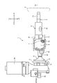
- FIG. 1 is a schematic side view of the steering device according to the first embodiment.
- FIG. FIG. 2 is a front view of the lower column and the fixing member according to the first embodiment viewed from the ⁇ X direction to the +X direction.
- 3 is a cross-sectional view taken along line III-III of FIG. 2.
- FIG. FIG. 4 is a schematic cross-sectional view enlarging the A portion of FIG. 3 .
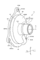
- FIG. 5 is a perspective view of the fixing member according to the first embodiment, viewed from the -X direction to the +X direction.
- FIG. 6 is a perspective view of the fixing member according to the first embodiment, viewed from the -X direction to the +X direction.
- FIG. 1 is a schematic side view of the steering device according to the first embodiment.
- FIG. FIG. 2 is a front view of the lower column and the fixing member according to the first embodiment viewed from the ⁇ X direction to the +X direction.
- 3 is a cross-sectional view taken along line III-III
- FIG. 7 is a perspective view of the fixing member according to the first embodiment, viewed from the +X direction to the ⁇ X direction.
- FIG. 8 is a perspective view of a fixing member according to the second embodiment, viewed from the -X direction to the +X direction.
- FIG. 9 is a perspective view looking up from the ⁇ Z direction to the +Z direction of the peripheral portion of the fixing member according to the second embodiment, showing a state in which the upper column has moved in the +X direction at the time of the secondary collision.
- 10 is a front view of the lower column, the upper column, and the fixing member in the state of FIG. 9, viewed from the -X direction to the +X direction.
- 11 is a cross-sectional view taken along line XI--XI of FIG. 10.
- FIG. 12 is a cross-sectional view taken along line XII-XII of FIG. 11.
- a direction parallel to the X axis is described as the X direction
- a direction parallel to the Y axis is described as the Y direction
- a direction parallel to the Z axis is described as the Z direction.
- the direction toward the front of the vehicle is the +X direction
- the direction toward the rear is the -X direction.
- the right direction is the +Y direction
- the left direction is the -Y direction.
- the upward direction is the +Z direction
- the downward direction is the -Z direction.
- the X direction is referred to as the "axial direction”
- the -X direction side is referred to as "one side in the axial direction”
- the +X direction side is referred to as the "other side in the axial direction”.
- FIG. 1 is a schematic side view of the steering device according to the first embodiment.
- the steering device 1 includes a steering wheel 2 , a steering shaft 3 , a steering column 4 , a gearbox 5 , a tilt bracket 6 , a tightening mechanism 7 and a motor 50 .
- the steering wheel 2 is connected to the end of the steering shaft 3 in the -X direction.
- the steering shaft 3 rotates about the central axis Ax, and an operation torque is applied to the steering shaft 3 .
- a gear box 5 is provided at the end of the steering column 4 in the +X direction.
- a motor 50 is assembled to the gearbox 5 .
- the motor 50 is an ECU (Electronic Control Unit) integrated motor. Therefore, the steering device 1 according to this embodiment is an electric power steering device in which the motor 50 assists the driver's steering.
- the steering shaft 3 includes an upper shaft 31 and a lower shaft 32.
- the upper shaft 31 and the lower shaft 32 are cylindrical shafts.
- the steering wheel 2 is attached to the ⁇ X direction end of the upper shaft 31 .
- the steering wheel 2 is connected to one side of the steering shaft 3 in the axial direction.
- the +X direction end of the upper shaft 31 is fitted onto the lower shaft 32 .
- the +X direction end of the upper shaft 31 and the ⁇ X direction end of the lower shaft 32 are spline-fitted. Therefore, the upper shaft 31 can slide in the X direction with respect to the lower shaft 32 .
- the steering column 4 is an outer cylinder extending in the X direction and arranged on the outer peripheral side of the steering shaft 3 .
- the steering column 4 has an upper column 41 , a lower column 42 and a fixing member 8 .
- the upper column 41 is a column arranged near the steering wheel 2 .
- the lower column 42 is a column arranged in the +X direction with respect to the upper column 41 and separated from the steering wheel 2 .
- the upper column 41 and the lower column 42 are cylindrical, and the +X direction end of the upper column 41 is fitted to the ⁇ X direction end of the lower column 42 . Then, during a secondary collision, the upper column 41 can move in the +X direction with respect to the lower column 42 .
- the +X direction end of the lower column 42 is fixed to the gear box 5 via the fixing member 8 .
- the fixed member 8 and the gearbox 5 are shown separately in FIG. 1, the present disclosure is not limited to this, and the fixed member 8 and the gearbox 5 may be integrated.
- the gearbox 5 includes a plate 51 and a body portion 52.
- the body portion 52 accommodates a plurality of gears inside.
- the plate 51 seals the ⁇ X direction opening of the body portion 52 . That is, the plate 51 is fixed to the fixing member 8 and the main body portion 52 while being sandwiched between the fixing member 8 and the main body portion 52 .
- the fixing member 8 will be described later in detail.
- a tilt bracket 6 is provided on the outer peripheral side of the steering column 4 .
- a tightening mechanism 7 is provided on the tilt bracket 6 .
- the tightening mechanism 7 includes an operating lever 71 and a tightening shaft 72 that supports the end of the operating lever 71 .
- the tilt bracket 6 is fixed to the vehicle body member 70 .
- the tilt spring 61 is, for example, a torsion coil spring. The tilt spring 61 applies an upward (+Z direction) force to the steering column 4 .
- the pivot bracket 62 is fixed to a vehicle body side member, and supports the steering column 4 so as to be able to swing around the swing center axis 300 . Thereby, the steering column 4 is supported so as to be swingable in the tilt direction.
- FIG. 2 is a front view of the lower column and the fixing member according to the first embodiment viewed from the -X direction to the +X direction.
- 3 is a cross-sectional view taken along line III-III of FIG. 2.
- FIG. FIG. 4 is a schematic cross-sectional view enlarging the A portion of FIG. 3 .
- FIG. 5 is a perspective view of the fixing member according to the first embodiment, viewed from the -X direction to the +X direction.
- FIG. 6 is a perspective view of the fixing member according to the first embodiment, viewed from the -X direction to the +X direction.
- FIG. 7 is a perspective view of the fixing member according to the first embodiment, viewed from the +X direction to the ⁇ X direction.
- the lower column 42 is a cylindrical member having a cylindrical shape along the circumferential direction around the central axis Ax.
- the +X-direction end portion 42 a of the lower column 42 is fitted to the outer peripheral side of the cylindrical portion 81 of the fixed member 8 .
- the fixing member 8 includes a cylindrical portion 81, a disc portion 82, and a flange portion 83.
- the fixing member 8 has an annular shape along the circumferential direction around the central axis Ax.
- the cylindrical portion 81 has a small diameter portion 811 , a curved portion 812 and a large diameter portion 813 .
- the small diameter portion 811 is positioned in the -X direction in the cylindrical portion 81.
- the outer peripheral surface of the small diameter portion 811 is a straight line along the axial direction.
- the curved portion 812 is adjacent to the small diameter portion 811 in the +X direction.
- the outer diameter of the outer peripheral surface of the curved portion 812 increases in the +X direction. That is, in a cross section including the central axis Ax, the outer peripheral surface of the curved portion 812 has an arc shape.
- the outer peripheral surface of the curved portion 812 is an arc having a radius of curvature r centered on the center C of the radius of curvature.
- the outer peripheral surface of curved portion 812 extends from end 812a to end 812b.
- the end 812a and the center C have the same position in the X direction.
- the straight line connecting the end 812a and the center C and the outer peripheral surface of the small diameter portion 811 are perpendicular to each other. Therefore, the tangent line of the end 812 a on the outer peripheral surface of the curved portion 812 coincides with the outer peripheral surface of the small diameter portion 811 .
- the large diameter portion 813 is adjacent to the curved portion 812 in the +X direction.
- the outer peripheral surface of the large diameter portion 813 is a straight line along the axial direction.
- the curvature radius r is larger than the radial difference H1 between the outer peripheral surface of the large diameter portion 813 and the small diameter portion 811 .
- the difference H1 is the difference between the radius of the large diameter portion 813 and the radius of the small diameter portion 811, and is also referred to as the first length.
- the radius of curvature r is four times the difference H1.
- the +X direction end 421 of the lower column 42 is positioned in the -X direction from the end 812a. That is, the +X-direction end 421 of the lower column 42 is arranged at the small-diameter portion 811 in the X-direction.
- the outer peripheral surface 422 of the lower column 42 is located radially outside the outer peripheral surface of the large-diameter portion 813, and in a cross section including the central axis Ax, the outer peripheral surface 422 of the lower column 42 and the outer peripheral surface of the large-diameter portion 813 are aligned. have a radial difference H2.
- the difference H2 is the difference between the radius of the outer peripheral surface 422 of the lower column 42 and the radius of the outer peripheral surface of the large diameter portion 813, and is also called a second length.
- the disc portion 82 has an annular shape extending radially outward around the central axis Ax.
- the ⁇ X direction surface of the disc portion 82 includes a flat surface 822 extending radially outward from the +X direction end 814 of the cylindrical portion 81 to the end 821 and extending from the end 821 to the end 823. a cylindrical surface 824;
- the flange portion 83 extends radially outward. 5 to 7, the flange portion 83 has projections 831, 832, and 833 projecting radially outward.
- the protrusions 831, 832, and 833 are provided at three locations at regular intervals along the circumferential direction around the central axis Ax.
- Through holes 831H, 832H and 833H are provided in the protrusions 831, 832 and 833, respectively.
- Bolts can be inserted into the through holes 831H, 832H, and 833H, and the collar portion 83 is fixed to the gearbox 5 via these bolts.
- the fixing member 8 has the cylindrical portion 81 extending in the axial direction.
- the cylindrical portion 81 has a small-diameter portion 811 fitted to the inner peripheral side of the lower column 42 and an outer peripheral surface adjacent to the other axial side of the small-diameter portion 811 and having an outer diameter that increases toward the other axial side. and a large-diameter portion 813 adjacent to the other axial side of the curved portion 812 and having an outer diameter larger than that of the small-diameter portion 811 .
- the difference between the radius of the large diameter portion 813 and the radius of the small diameter portion 811 is the difference H1 (first length).
- the outer peripheral surface of the curved portion 812 is an arc having a radius of curvature r larger than the difference H1 (first length), and is tangent to one end of the arc in the axial direction. coincides with the outer peripheral surface of the small diameter portion 811 .
- the outer diameter of large diameter portion 813 is smaller than the outer diameter of lower column 42 .
- the driver applies force to the steering wheel 2 toward the front of the vehicle (+X direction).
- force is transmitted from the steering wheel 2 to the upper column 41 via the steering shaft 3 .
- the upper column 41 is fitted to the outer peripheral side of the lower column 42, but when the force transmitted to the upper column 41 becomes larger than the fitting force with the lower column 42, the upper column 41 moves the outer peripheral side of the lower column 42 forward ( +X direction).
- the upper column 41 will interfere with the large diameter portion 813 when the upper column 41 moves forward. It is possible to move to the vicinity of the disc portion 82 without any movement. Therefore, compared to the case where the outer diameter of the large diameter portion 813 is larger than the outer diameter of the lower column 42, the movement amount (stroke amount) of the upper column 41 at the time of the secondary collision is increased.
- the outer diameter of the large diameter portion 813 is smaller than the outer diameter of the lower column 42, the thickness of the large diameter portion 813 in the radial direction is reduced, and the rigidity of the large diameter portion 813 is reduced.
- the gap between the large-diameter portion 813 and the small-diameter portion 811 is reduced. The force is concentrated on the curved portion 812 located at .
- the outer peripheral surface of the curved portion 812 is formed into an arc shape with a large radius of curvature, and the step at the boundary portion between the curved portion 812 and the small diameter portion 811 is minimized. As a result, even when force is concentrated on the bending portion 812, deformation and damage to the bending portion 812 can be suppressed to a smaller extent.
- the other end 421 of the lower column 42 in the axial direction is located on one side in the axial direction of the one end 812 a of the curved portion 812 in the axial direction.
- FIG. 8 is a perspective view of a fixing member according to the second embodiment, viewed from the -X direction to the +X direction.
- FIG. 9 is a perspective view looking up from the ⁇ Z direction to the +Z direction of the peripheral portion of the fixing member according to the second embodiment, showing a state in which the upper column has moved in the +X direction at the time of the secondary collision.
- 10 is a front view of the lower column, the upper column, and the fixing member in the state of FIG. 9, viewed from the -X direction to the +X direction.
- 11 is a cross-sectional view taken along line XI--XI of FIG. 10.
- FIG. 12 is a cross-sectional view taken along line XII-XII of FIG. 11.
- the second embodiment differs from the first embodiment in that ribs are provided on the surface side (the side in the -X direction) of the fixing member. Details are given below.
- the disc portion 82 of the fixing member 8A of the steering column 4A has ribs 200 on the front side (one side in the axial direction, the side in the -X direction).
- the rib 200 has a triangular shape when viewed from the side.
- the rib 200 protrudes from the flat surface 822 in the -X direction.
- the rib 200 extends radially outward of the disc portion 82 .
- Rib 200 is fixed to cylindrical portion 81 .
- the height of the rib 200 is the highest at the end 201 on the large diameter portion 813 side of the cylindrical portion 81 and the lowest at the radially outer end 202 . Therefore, the upper surface 210 of the rib 200 becomes lower as it goes radially outward from the end 201 on the large diameter portion 813 side.
- FIG. 9 to 12 show the state in which the upper column 41 has moved in the +X direction to the fixed member 8A during the secondary collision. That is, at the time of the secondary collision, the driver applies force to the steering wheel 2 toward the front of the vehicle. In this case, force is transmitted from the steering wheel 2 to the upper column 41 via the steering shaft 3 . Normally, the upper column 41 is fitted to the lower column 42, but when the force transmitted to the upper column 41 becomes larger than the fitting force with the lower column 42, the upper column 41 slides on the outer peripheral side of the lower column 42. Moving. As described above, during a secondary collision, the front end of the upper column 41 may be positioned near the fixed member 8A as shown in FIG.
- a projecting portion 410 projecting downward is provided below (-Z direction) in the upper column 41 .
- Protruding portion 410 has a U-shape in a cross section orthogonal to central axis Ax.
- the projecting portion 410 includes a pair of left and right first and second plate portions 411 and 412 extending in the Z direction, and a connecting plate 413 connecting the lower end of the first plate portion 411 and the lower end of the second plate portion 412.
- the recessed portion 414 surrounded by the first plate portion 411 and the second plate portion 412 and the connecting plate 413 is larger than the maximum height of the rib 200 (that is, the height at the end 201 on the large diameter portion 813 side of the cylindrical portion 81). Has great height.
- three projections 415 projecting radially outward are provided on the outer peripheral surface of the end of the upper column 41 in the -X direction.
- a through hole 415 ⁇ /b>H is formed in the projection 415 so as to penetrate in the plate thickness direction.
- the fixing member 8A has the disc portion 82 provided on the other axial side of the cylindrical portion 81 and extending in the radial direction.
- the disc portion 82 has a rib 200 that protrudes from one axial side surface to one axial side and is fixed to the cylindrical portion 81 .
- the rib 200 extends radially outward in the -X direction from the disk portion 82, the rigidity of the disk portion 82 and the cylindrical portion 81 is improved by the rib 200.
- the upper column 41 has a protruding portion 410 capable of accommodating the rib 200 at the other end in the axial direction. According to this, it is possible to suppress interference between the upper column 41 and the rib 200 when the upper column 41 moves forward with respect to the lower column 42 in the secondary collision.
Landscapes
- Engineering & Computer Science (AREA)
- Chemical & Material Sciences (AREA)
- Combustion & Propulsion (AREA)
- Transportation (AREA)
- Mechanical Engineering (AREA)
- Steering Controls (AREA)
Priority Applications (4)
| Application Number | Priority Date | Filing Date | Title |
|---|---|---|---|
| CN202280009462.2A CN116710347A (zh) | 2021-02-04 | 2022-02-02 | 转向装置 |
| US18/275,710 US12077208B2 (en) | 2021-02-04 | 2022-02-02 | Steering device |
| DE112022000351.0T DE112022000351T5 (de) | 2021-02-04 | 2022-02-02 | Lenkvorrichtung |
| JP2022579565A JP7742369B2 (ja) | 2021-02-04 | 2022-02-02 | ステアリング装置 |
Applications Claiming Priority (2)
| Application Number | Priority Date | Filing Date | Title |
|---|---|---|---|
| JP2021016247 | 2021-02-04 | ||
| JP2021-016247 | 2021-02-04 |
Publications (1)
| Publication Number | Publication Date |
|---|---|
| WO2022168850A1 true WO2022168850A1 (ja) | 2022-08-11 |
Family
ID=82741531
Family Applications (1)
| Application Number | Title | Priority Date | Filing Date |
|---|---|---|---|
| PCT/JP2022/003987 Ceased WO2022168850A1 (ja) | 2021-02-04 | 2022-02-02 | ステアリング装置 |
Country Status (5)
| Country | Link |
|---|---|
| US (1) | US12077208B2 (https=) |
| JP (1) | JP7742369B2 (https=) |
| CN (1) | CN116710347A (https=) |
| DE (1) | DE112022000351T5 (https=) |
| WO (1) | WO2022168850A1 (https=) |
Citations (6)
| Publication number | Priority date | Publication date | Assignee | Title |
|---|---|---|---|---|
| JP2002081420A (ja) * | 2000-09-05 | 2002-03-22 | Kao Corp | パイプの連結構造 |
| JP2004136749A (ja) * | 2002-10-16 | 2004-05-13 | Showa Corp | ステアリング装置のステアリングコラム |
| JP2005502415A (ja) * | 2001-09-20 | 2005-01-27 | ザ プロクター アンド ギャンブル カンパニー | クリーニング用具 |
| WO2008146664A1 (ja) * | 2007-05-25 | 2008-12-04 | Nsk Ltd. | 電動パワーステアリング装置 |
| JP2013035486A (ja) * | 2011-08-10 | 2013-02-21 | Nsk Ltd | ステアリング装置 |
| WO2017072032A1 (de) * | 2015-10-27 | 2017-05-04 | Thyssenkrupp Presta Ag | Lenksäule für ein kraftfahrzeug und verfahren zur herstellung einer lenksäule |
Family Cites Families (51)
| Publication number | Priority date | Publication date | Assignee | Title |
|---|---|---|---|---|
| US3635314A (en) * | 1966-06-17 | 1972-01-18 | Ara Inc | Linear-type energy absorber having circular elements between cylinders |
| US3492888A (en) * | 1966-11-24 | 1970-02-03 | Nissan Motor | Steering assembly for absorbing impact |
| US3600970A (en) * | 1969-08-22 | 1971-08-24 | Chrysler Corp | Steering column |
| US3665778A (en) * | 1970-09-02 | 1972-05-30 | Ford Motor Co | Energy absorbing steering column |
| US3699824A (en) * | 1971-04-05 | 1972-10-24 | Ford Motor Co | Energy absorbing steering column for a motor vehicle |
| US3877319A (en) * | 1973-11-19 | 1975-04-15 | Gen Motors Corp | Steering column assembly |
| US4003537A (en) * | 1976-01-19 | 1977-01-18 | Melvin Mutchnik | Mountings for tubular metal legs |
| US4189249A (en) * | 1977-04-15 | 1980-02-19 | Gulf & Western Manufacturing Company | Replacement torque rod assembly |
| JPH085095Y2 (ja) * | 1989-12-11 | 1996-02-14 | 日本精工株式会社 | 衝撃吸収式ステアリングコラム装置 |
| GB9215995D0 (en) * | 1992-07-28 | 1992-09-09 | Torrington Co | Vehicel crash energy absorbing mechanism |
| US5273330A (en) * | 1992-11-23 | 1993-12-28 | General Motors Corporation | Twist-lock mounting assembly and method for a bumper energy absorber |
| FR2704032B1 (fr) * | 1993-04-14 | 1995-07-21 | Nadella | Palier à roulement précontraint à cage perfectionnée et son application notamment à une colonne de direction. |
| JP3168841B2 (ja) * | 1994-09-22 | 2001-05-21 | 日本精工株式会社 | 衝撃吸収式ステアリングシャフトの製造方法 |
| AU4437196A (en) * | 1995-01-05 | 1996-07-24 | Felice Ballin | Variable-length steering-gear control shaft for motor vehicles |
| GB2298448A (en) * | 1995-03-02 | 1996-09-04 | Torrington Co | Steering column locking assembly |
| GB2353768A (en) * | 1999-08-28 | 2001-03-07 | Rover Group | Collapsible vehicle steering column |
| JP4000781B2 (ja) * | 2001-03-01 | 2007-10-31 | 株式会社ジェイテクト | ステアリング装置 |
| JP2003035320A (ja) * | 2001-05-16 | 2003-02-07 | Nsk Ltd | 弾性軸継手および弾性ブッシュの製造方法 |
| US6938724B2 (en) * | 2003-03-18 | 2005-09-06 | Toyoda Koki Kabushiki Kaisha | Motor vehicle steering device |
| JP2004352011A (ja) * | 2003-05-28 | 2004-12-16 | Toyota Motor Corp | 車両用ステアリング中間シャフト |
| EP1637433A4 (en) * | 2003-06-20 | 2007-10-10 | Nsk Ltd | DIRECTION DEVICE FOR A MOTOR VEHICLE |
| JP4516431B2 (ja) * | 2004-04-26 | 2010-08-04 | 本田技研工業株式会社 | ウォームギヤ機構及びウォームギヤ機構を搭載した電動パワーステアリング装置 |
| WO2007055296A1 (ja) * | 2005-11-10 | 2007-05-18 | Nsk Ltd. | 電動式パワーステアリング装置 |
| JP2007276591A (ja) | 2006-04-05 | 2007-10-25 | Jtekt Corp | パワーステアリング装置 |
| JP4512128B2 (ja) * | 2007-10-25 | 2010-07-28 | 本田技研工業株式会社 | モータの回転角検出装置 |
| US7866435B2 (en) * | 2008-04-21 | 2011-01-11 | Nexteer (Beijing) Technology Co., Ltd. | Electric power steering rotation isolator |
| GB0808798D0 (en) * | 2008-05-15 | 2008-06-18 | Trw Ltd | Adjustable steering column assembly |
| JP5120159B2 (ja) * | 2008-09-03 | 2013-01-16 | 日本精工株式会社 | 衝撃吸収式電動パワーステアリング装置 |
| DE102009054655A1 (de) * | 2009-12-15 | 2011-06-16 | Zf Lenksysteme Gmbh | Lenkgetriebe mit Festlager und Loslager für Schraubritzel |
| JP5048804B2 (ja) * | 2010-03-31 | 2012-10-17 | 日立オートモティブシステムズ株式会社 | パワーステアリング装置 |
| JP2013071679A (ja) * | 2011-09-28 | 2013-04-22 | Showa Corp | 電動パワーステアリング装置 |
| US9254861B2 (en) * | 2012-05-25 | 2016-02-09 | Nsk Ltd. | Electric steering wheel position adjustment apparatus |
| EP2913246B1 (en) * | 2012-10-29 | 2019-03-27 | NSK Ltd. | Electric power-steering device |
| US9540030B2 (en) * | 2013-03-12 | 2017-01-10 | Steering Solutions Ip Holding Corporation | Steering column assembly with improved bearing assembly |
| JP6332467B2 (ja) * | 2014-09-26 | 2018-05-30 | 日本精工株式会社 | トルク伝達用継手及び電動式パワーステアリング装置 |
| FR3041055B1 (fr) * | 2015-09-16 | 2017-10-06 | Jtekt Europe Sas | Reducteur a engrenage avec graisseur integre pour direction assistee |
| DE102015119047A1 (de) * | 2015-11-05 | 2017-05-11 | Thyssenkrupp Ag | Schwenklager für höhenverstellbare Lenksäule |
| JP6694739B2 (ja) * | 2016-03-25 | 2020-05-20 | 富士機工株式会社 | ステアリングコラム装置 |
| GB201616486D0 (en) * | 2016-09-28 | 2016-11-09 | Trw Limited | A gearbox assembly for an electric power steering apparatus |
| KR102668785B1 (ko) * | 2017-01-10 | 2024-05-24 | 에이치엘만도 주식회사 | 자동차의 조향컬럼 |
| KR102635281B1 (ko) * | 2017-02-01 | 2024-02-13 | 에이치엘만도 주식회사 | 전동식 동력 보조 조향장치의 감속기 |
| WO2018156882A1 (en) * | 2017-02-24 | 2018-08-30 | Webco Industries, Inc. | Crush guiding tubes and methods for same |
| EP3604845A4 (en) * | 2017-03-30 | 2020-11-04 | NSK Ltd. | TORQUE TRANSFER JOINT AND ELECTRIC POWER STEERING DEVICE |
| JP6777229B2 (ja) * | 2017-06-14 | 2020-10-28 | 日本精工株式会社 | ステアリングコラム装置 |
| FR3075744B1 (fr) * | 2017-12-27 | 2020-12-04 | Robert Bosch Automotive Steering Vendome | Colonne de direction |
| US11498610B2 (en) * | 2018-07-31 | 2022-11-15 | Steering Solutions Ip Holding Corporation | Shaft coupling assembly |
| JP7079689B2 (ja) * | 2018-08-07 | 2022-06-02 | 日立Astemo株式会社 | ステアリング装置 |
| US11498616B2 (en) * | 2019-03-07 | 2022-11-15 | Trw Automotive U.S. Llc | Apparatus for use in turning steerable vehicle wheels |
| JP7389579B2 (ja) * | 2019-07-18 | 2023-11-30 | Ntn株式会社 | 回転伝達装置および車両用操舵装置 |
| US11396936B2 (en) * | 2020-03-17 | 2022-07-26 | Mando Corporation | Reducer of power steering apparatus for vehicle |
| CN116648399A (zh) * | 2020-12-24 | 2023-08-25 | 日本精工株式会社 | 转向装置 |
-
2022
- 2022-02-02 US US18/275,710 patent/US12077208B2/en active Active
- 2022-02-02 CN CN202280009462.2A patent/CN116710347A/zh active Pending
- 2022-02-02 JP JP2022579565A patent/JP7742369B2/ja active Active
- 2022-02-02 DE DE112022000351.0T patent/DE112022000351T5/de active Pending
- 2022-02-02 WO PCT/JP2022/003987 patent/WO2022168850A1/ja not_active Ceased
Patent Citations (6)
| Publication number | Priority date | Publication date | Assignee | Title |
|---|---|---|---|---|
| JP2002081420A (ja) * | 2000-09-05 | 2002-03-22 | Kao Corp | パイプの連結構造 |
| JP2005502415A (ja) * | 2001-09-20 | 2005-01-27 | ザ プロクター アンド ギャンブル カンパニー | クリーニング用具 |
| JP2004136749A (ja) * | 2002-10-16 | 2004-05-13 | Showa Corp | ステアリング装置のステアリングコラム |
| WO2008146664A1 (ja) * | 2007-05-25 | 2008-12-04 | Nsk Ltd. | 電動パワーステアリング装置 |
| JP2013035486A (ja) * | 2011-08-10 | 2013-02-21 | Nsk Ltd | ステアリング装置 |
| WO2017072032A1 (de) * | 2015-10-27 | 2017-05-04 | Thyssenkrupp Presta Ag | Lenksäule für ein kraftfahrzeug und verfahren zur herstellung einer lenksäule |
Also Published As
| Publication number | Publication date |
|---|---|
| DE112022000351T5 (de) | 2023-11-16 |
| US20240116557A1 (en) | 2024-04-11 |
| JPWO2022168850A1 (https=) | 2022-08-11 |
| US12077208B2 (en) | 2024-09-03 |
| JP7742369B2 (ja) | 2025-09-19 |
| CN116710347A (zh) | 2023-09-05 |
Similar Documents
| Publication | Publication Date | Title |
|---|---|---|
| EP3647157B1 (en) | Vehicle steering apparatus | |
| US8360927B2 (en) | Vehicle power transmission device | |
| JP5708838B2 (ja) | ステアリング装置 | |
| EP1884446B1 (en) | Steering apparatus equipped with ring type support yoke | |
| EP3141456A1 (en) | Steering system | |
| WO2022168850A1 (ja) | ステアリング装置 | |
| EP2778469B1 (en) | Wheel driving apparatus | |
| JP7742368B2 (ja) | ステアリング装置 | |
| JP5015751B2 (ja) | シャフトの結合構造 | |
| JP5496233B2 (ja) | 変速機のコントロールワイヤ支持構造 | |
| JP4721044B2 (ja) | 円筒部材の取付構造 | |
| JP2023019496A (ja) | 電動パワーステアリング装置およびその製造方法 | |
| JP7846561B2 (ja) | ステアリング装置 | |
| JP7596005B2 (ja) | ステアリング装置およびステアリング装置の製造方法 | |
| KR102779335B1 (ko) | 베어링 및 이를 포함하는 스티어링 장치 | |
| WO2025215870A1 (ja) | ステアリング装置 | |
| KR20250010965A (ko) | 유성기어 감속기 및 이를 포함하는 조향 반력 모터 | |
| JP7178797B2 (ja) | ステアリング装置 | |
| JP2019206221A (ja) | 電動パワーステアリング装置 | |
| KR20250010966A (ko) | 유성기어 감속기 및 이를 포함하는 조향 반력 모터 | |
| JP2025170959A (ja) | 回転センサ一体型軸受 | |
| JP2022090202A (ja) | ステアリング装置 | |
| WO2025197001A1 (ja) | 車両用駆動装置 | |
| JP2014151724A (ja) | ステアリングコラム装置 | |
| JP2015186936A (ja) | ステアリング装置 |
Legal Events
| Date | Code | Title | Description |
|---|---|---|---|
| 121 | Ep: the epo has been informed by wipo that ep was designated in this application |
Ref document number: 22749721 Country of ref document: EP Kind code of ref document: A1 |
|
| WWE | Wipo information: entry into national phase |
Ref document number: 202280009462.2 Country of ref document: CN |
|
| ENP | Entry into the national phase |
Ref document number: 2022579565 Country of ref document: JP Kind code of ref document: A |
|
| WWE | Wipo information: entry into national phase |
Ref document number: 112022000351 Country of ref document: DE |
|
| WWE | Wipo information: entry into national phase |
Ref document number: 18275710 Country of ref document: US |
|
| 122 | Ep: pct application non-entry in european phase |
Ref document number: 22749721 Country of ref document: EP Kind code of ref document: A1 |