WO2022130943A1 - モデリング支援方法、情報処理装置、及び、プログラム - Google Patents
モデリング支援方法、情報処理装置、及び、プログラム Download PDFInfo
- Publication number
- WO2022130943A1 WO2022130943A1 PCT/JP2021/043501 JP2021043501W WO2022130943A1 WO 2022130943 A1 WO2022130943 A1 WO 2022130943A1 JP 2021043501 W JP2021043501 W JP 2021043501W WO 2022130943 A1 WO2022130943 A1 WO 2022130943A1
- Authority
- WO
- WIPO (PCT)
- Prior art keywords
- line
- display device
- input operation
- displaying
- control structure
- Prior art date
- Legal status (The legal status is an assumption and is not a legal conclusion. Google has not performed a legal analysis and makes no representation as to the accuracy of the status listed.)
- Ceased
Links
Images











Classifications
-
- G—PHYSICS
- G06—COMPUTING OR CALCULATING; COUNTING
- G06F—ELECTRIC DIGITAL DATA PROCESSING
- G06F3/00—Input arrangements for transferring data to be processed into a form capable of being handled by the computer; Output arrangements for transferring data from processing unit to output unit, e.g. interface arrangements
- G06F3/01—Input arrangements or combined input and output arrangements for interaction between user and computer
- G06F3/048—Interaction techniques based on graphical user interfaces [GUI]
- G06F3/0484—Interaction techniques based on graphical user interfaces [GUI] for the control of specific functions or operations, e.g. selecting or manipulating an object, an image or a displayed text element, setting a parameter value or selecting a range
- G06F3/04842—Selection of displayed objects or displayed text elements
-
- G—PHYSICS
- G06—COMPUTING OR CALCULATING; COUNTING
- G06F—ELECTRIC DIGITAL DATA PROCESSING
- G06F3/00—Input arrangements for transferring data to be processed into a form capable of being handled by the computer; Output arrangements for transferring data from processing unit to output unit, e.g. interface arrangements
- G06F3/01—Input arrangements or combined input and output arrangements for interaction between user and computer
- G06F3/048—Interaction techniques based on graphical user interfaces [GUI]
- G06F3/0484—Interaction techniques based on graphical user interfaces [GUI] for the control of specific functions or operations, e.g. selecting or manipulating an object, an image or a displayed text element, setting a parameter value or selecting a range
- G06F3/04845—Interaction techniques based on graphical user interfaces [GUI] for the control of specific functions or operations, e.g. selecting or manipulating an object, an image or a displayed text element, setting a parameter value or selecting a range for image manipulation, e.g. dragging, rotation, expansion or change of colour
-
- G—PHYSICS
- G06—COMPUTING OR CALCULATING; COUNTING
- G06F—ELECTRIC DIGITAL DATA PROCESSING
- G06F3/00—Input arrangements for transferring data to be processed into a form capable of being handled by the computer; Output arrangements for transferring data from processing unit to output unit, e.g. interface arrangements
- G06F3/01—Input arrangements or combined input and output arrangements for interaction between user and computer
- G06F3/048—Interaction techniques based on graphical user interfaces [GUI]
- G06F3/0484—Interaction techniques based on graphical user interfaces [GUI] for the control of specific functions or operations, e.g. selecting or manipulating an object, an image or a displayed text element, setting a parameter value or selecting a range
- G06F3/04847—Interaction techniques to control parameter settings, e.g. interaction with sliders or dials
-
- G—PHYSICS
- G06—COMPUTING OR CALCULATING; COUNTING
- G06F—ELECTRIC DIGITAL DATA PROCESSING
- G06F8/00—Arrangements for software engineering
- G06F8/30—Creation or generation of source code
- G06F8/33—Intelligent editors
Definitions
- the disclosure of this specification relates to modeling support methods, information processing devices, and programs.
- the conventional programming language used for programming requires writing program code, and the hurdle is too high for beginners including elementary school students to learn programming for the first time.
- branching and iteration are the basic control structures of a program as well as sequential.
- the control structure is represented graphically, the graphical representation of branching and iteration is more complicated than that of sequential. Therefore, even in visual programming, GUI operations for realizing branching and repetition tend to be more complicated than those in sequence.
- the explanation was made assuming a programming tool for visual programming, but similar problems can occur not only in the program implementation process but also in the design process. Therefore, the above-mentioned problems are common to all modeling tools including programming tools. Further, the above-mentioned problems in the modeling tool are not limited to the design of the program running on the computer, but may occur in the design of the entire processing flow including, for example, the business flow.
- an object of one aspect of the present invention is to provide a technique for improving the operability of a modeling tool used for designing or programming a processing flow.
- the modeling support method is a process performed by a computer for displaying on a display device a line on which one or more elements indicating a control structure, each of which is classified into sequential, branching, or iterative, can be arranged.
- a computer for displaying on a display device a line on which one or more elements indicating a control structure, each of which is classified into sequential, branching, or iterative, can be arranged.
- the process of detecting an input operation on the line or an element on the line displayed on the display device and the detected input operation include an operation in a direction intersecting the line, the branch or the branch or the element on the line is included.
- the process includes displaying a new element indicating a control structure classified into the iteration on the display device.
- the information processing apparatus includes one or more non-temporary computer-readable media including instructions and one or more processors that execute the instructions.
- the instruction is configured to cause the one or more processors to perform an operation, where the operation is a line on which one or more elements can be placed, each representing a control structure classified as sequential, branching, or iterative.
- the display device comprises displaying a new element on the line indicating a control structure classified into the branch or the iteration.
- the program according to one aspect of the present invention causes a computer to display on a display device a line on which one or more elements can be arranged, indicating a control structure in which each is classified into sequential, branching, or iterative.
- a computer to display on a display device a line on which one or more elements can be arranged, indicating a control structure in which each is classified into sequential, branching, or iterative.
- the input operation is classified as the branch or the iteration on the line.
- the process of displaying a new element indicating the control structure on the display device is executed.
- the operability of the modeling tool can be improved.
- the modeling tool means an application program that supports the modeling work performed by the user, and / or a computer on which the program operates. That is, the modeling tool is at least one of software, hardware, or a combination thereof that supports the modeling work.
- the modeling tool is a desktop application program or an information processing device (hereinafter, also referred to as a user terminal) directly operated by a user in which the desktop application program is installed will be described as an example. ..
- the modeling tool may be a web application program, or may be an information processing device different from the user terminal on which the web application program is deployed. That is, the modeling tool may provide a GUI on the web browser of the user terminal.
- the modeling tool is a visual programming tool that converts a program represented graphically using elements (objects) such as figures into a text format program code (source code) and executes it.
- objects elements
- source code text format program code
- the modeling tool is not limited to a programming tool that creates and executes source code, and may be, for example, a drawing tool that draws a flowchart of processing executed by a computer. Further, the modeling tool may be used as a drawing tool for drawing a business flow.
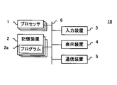
- FIG. 1 is an external view of the information processing apparatus 10 according to the present embodiment.
- FIG. 2 is a hardware configuration diagram of the information processing apparatus 10 according to the present embodiment.
- the information processing apparatus 10 is, for example, a tablet terminal provided with a touch panel display, and is a computer in which a program for visual programming is installed.
- the information processing device 10 may be a touch device having a touch panel display, and is not limited to a tablet terminal.
- the information processing device 10 may be, for example, a laptop computer, a smartphone, an electronic dictionary, or the like.
- the present invention is not limited to a mobile terminal, and may be, for example, a table-type computer in which a touch panel display is embedded in a table.
- the information processing device 10 includes one or more processors 1, one or more storage devices 2, an input device 3, a display device 4, and a communication device 5. Further, in the information processing apparatus 10, they are connected through the bus 6.
- the input device 3 and the display device 4 constitute a touch panel display, and are arranged so as to overlap each other as shown in FIG.
- Each of the one or more processors 1 is hardware including, for example, a CPU (Central Processing Unit), and executes a program 2a stored in the storage device 2.
- the CPU includes a control device, an arithmetic unit, a register, a cache memory, and the like, and further includes an interface with another device and the like.
- One or more processors 1 may include a GPU (Graphics processing unit), an ASIC (Application Specific Integrated Circuit), an FPGA (Field-Programmable Gate Array), a DSP (Digital Sensor), etc.
- Each of the one or more storage devices 2 is a non-temporary computer-readable medium, for example, an arbitrary semiconductor memory.
- the one or more storage devices 2 include a volatile memory such as a RAM (Random Access Memory), a non-volatile memory such as a ROM (Read Only Memory), and a flash memory. Further, the storage device 2 may include a magnetic storage device, an optical storage device, and other types of storage devices.
- At least one of the one or more storage devices 2 contains the program 2a.
- Program 2a is a visual programming tool and includes instructions for programming support processing described later. Further, the instructions included in the program 2a are configured to cause one or more processors 1 to execute a predetermined operation.
- the input device 3 is a device directly operated by the user.
- the input device 3 is a touch sensor constituting a touch panel display.
- the detection method of the touch sensor is not particularly limited. For example, any detection method such as a resistance film method, a capacitance method, an electromagnetic induction method, an ultrasonic surface acoustic wave method, and an infrared method can be adopted.
- the display device 4 is, for example, a liquid crystal display, an organic EL display, or the like, but may be another type of display.
- the communication device 5 is a device for communicating with an external device.
- the communication device 5 is, for example, a wireless communication device such as a Wi-Fi module.
- the visual programming performed by the user using the information processing device 10 configured as described above is to create a program by arranging the elements showing the control structure of the programming on the screen.
- the programming support process performed by the information processing apparatus 10 controls the screen display according to the input operation of the user when the visual programming is performed.
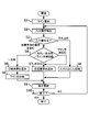
- FIG. 3 is a flowchart showing an example of programming support processing performed by the information processing apparatus 10.
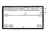
- FIG. 4 is a diagram showing a configuration example of a screen displayed on the information processing apparatus 10.
- the programming support process shown in FIG. 3 is an example of the modeling support process, and is started by executing an instruction included in the program 2a stored in the storage device 2 by one or more processors 1.
- the processor 1 causes the display device 4 to display a line on which one or more elements indicating a control structure, each of which is classified into sequential, branching, or repeating, can be arranged (step S1).
- step S1 for example, when the user taps the software button described as “New” in the area 12, the processor 1 causes the line L to be displayed in the area 12 of the display device 4 shown in FIG.
- Area 12 is a programming area in which a program designed by a user is expressed using a graphic.
- the line L displayed in the region 12 shows the flow of processing of the program from one end of the line L described as “START” to the other end of the line L described as “END”.
- Elements indicating the control structure displayed in the area 11 can be selectively arranged on the line L according to the operation of the user.
- an element indicating a control structure classified into sequential, branching, or iterative will be simply referred to as a control element.
- the processor 1 monitors the input operation to the input device 3. Then, when the input operation is performed, the processor 1 detects the input operation based on the output from the input device 3 (step S2). In step S2, the processor 1 detects the user's input operation based on the operation signal output by the input device 3 (touch sensor) in response to the input operation on the user's touch panel display.
- step S3 When it is determined in step S3 that the input operation detected in step S2 is (1) an operation on the line L or a control element on the line L, and (2) includes an operation in a direction intersecting the line L. ,
- the processor 1 causes the display device 4 to display a new control element classified as a branch or an iteration on the line L (steps S4 to S7, step S9).
- the processor 1 detects an input operation on the line L or an element on the line L, and if the detected input operation includes an operation in a direction intersecting the line L, the processor 1 is classified as a branch or an iteration on the line L.
- the new control element is displayed on the display device 4.
- step S2 when the input operation detected in step S2 is a one-way operation in a direction intersecting the line L with respect to the line L or an element on the line (step S4: one direction), the processor 1 is on the line L.
- a new control element (branch element) classified as a branch is displayed on the display device 4. More specifically, the processor 1 branches the line L (step S5), adds a branch element to the branch point (step S6), and updates the screen display (step S9).
- the one-way operation is, for example, flicking, swiping, sliding, or the like.
- step S2 when the input operation detected in step S2 is a bidirectional operation in a direction intersecting the line L with respect to the line L or an element on the line (step S4: bidirectional), the processor 1 classifies the input operation into iterations on the line L.
- the new control element (repetition element) to be displayed is displayed on the display device 4. That is, the processor 1 adds a repeating element (step S7) and updates the screen display (step S9).
- the bidirectional operation is, for example, a set of flicks in opposite directions, a set of swipes in opposite directions, a slide that draws a trajectory that folds back and forth in the middle, and the like.
- step S4 arc straddling the line
- the processor 1 is a new control element (repetition) classified as an iteration on the line L. Element) is displayed on the display device 4. That is, the processor 1 adds a repeating element (step S7) and updates the screen display (step S9).
- step S3 determines whether the input operation detected in step S2 does not satisfy the operations (1) and (2) described later.
- the processor 1 performs a process according to the input operation (step S8).
- the screen display of the display device 4 is updated (step S9).
- the input operation targeted in step S8 is not particularly limited, and may include, for example, taps, double taps, long taps, pinch-ins, pinch-outs, flicks, swipes, slides, and the like for the area 11 or the area 12. ..
- the process corresponding to these input operations may include, for example, a process of displaying new control elements classified sequentially on the line L.
- the processor 1 determines whether or not the end instruction has been input (step S10), and when it is determined that the end instruction has been input, the processor 1 ends the programming support process shown in FIG. On the other hand, if it is determined that the end instruction has not been input, the processor 1 repeats the processes of steps S2 to S9 until the end instruction is input.
- the information processing apparatus 10 can add a control structure classified into branching and repetition to the program by intuitive and simple operation by executing the programming support process shown in FIG. 3 described above.
- the operability of the programming tool is improved as compared with the conventional case, so that the user of the programming tool can concentrate on programming without interrupting thinking and can efficiently perform programming learning. ..
- even beginners who are unfamiliar with programming and programming tools can operate it intuitively, so compared to conventional programming tools, there is less confusion about how to use programming tools. Therefore, it is possible to avoid a situation in which programming learning itself is abandoned at an initial stage due to difficulty in mastering programming tools.
- FIG. 5 is a diagram for explaining an example of a method of adding an element showing a control structure.
- FIG. 6 is a diagram for explaining an example of a method of setting element parameters.
- FIG. 7 is a diagram for explaining an example of a method of changing the order of the elements showing the control structure.
- a method of adding a control element to the region 12 will be described with reference to FIGS. 5 to 7.
- the user When adding a control element, the user may long-tap on the line L as shown in FIG. 5, and the new control element 21 is added to the long-tapped position. Further, the type of the control element can be freely switched from any control element displayed in the area 11 by flicking the control element 21 added on the line L to the left or right.
- control element may be added by dragging the control element displayed in the area 11 onto the line L and dropping it at the position to be added.
- parameter settings for each control element can be performed by long-tapping the control element added on the line L.
- the setting window 23 for parameter setting is displayed.
- Parameters can be set for control elements by entering or selecting information in the items in the settings window 23.
- the order of the control elements added on the line L can be changed later. For example, as shown in FIG. 7, tap the control element 25 to select it as a movement target. After that, the control element 25 selected as the movement target can be moved to a desired position by dragging and dropping the control element 25 at a desired position. For example, if the control elements are set to be aligned at regular intervals, the intervals between the control elements may be maintained by moving other control elements in accordance with the movement of the control element 25. .. In the example shown in FIG. 7, it is shown that each of the control elements 29 moves forward from the control element 26 due to the backward movement of the control element 25.
- FIG. 8 is a diagram for explaining an example of a method of adding an element indicating a branch.
- FIG. 9 is a diagram for explaining an example of a method of setting parameters of elements indicating branches.
- FIG. 10 is a diagram for explaining an example of an operation method for branching.
- FIG. 11 is a diagram for explaining another example of the operation method for branching.
- the method of adding an arbitrary control element has been described, but hereinafter, a method peculiar to the case of adding a control element (branch element) classified into a branch will be described with reference to FIGS. 8 to 11. do.
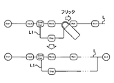
- the user When adding a branch element, as shown in FIG. 8, the user first taps and selects the control element 31 corresponding to the process to be executed only under specific conditions. After that, the selected control element 31 may be dragged and dropped or flicked in the direction intersecting the line L.
- the operation on the control element 31 is not limited to drag and drop and flick, and may be a one-way operation in a direction intersecting the line L. Specifically, for example, it may be a swipe, a slide, or the like.
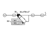
- a new line L1 branched from the line L is added to the control element 31 on the line L1 as shown in FIG.
- a branch element 32 is added as a new control element to the branch point where the line L branches to the line L1.
- the parameter setting for the branch element can be performed by long-tapping the branch element 32 added on the line L. This point is the same as the case where the parameter is set for an arbitrary control element as described above in FIG.
- the branch condition can be set in the setting window 33.
- control element 34 corresponding to the process is dragged to branch the line (line L, line L1). ) Just drop it at the desired position above.
- the position of another control element may be automatically adjusted by moving the control element 34.
- FIG. 10 shows how a new control element 36 is added to the space secured by such an operation.
- the flick may be programmed so that the branches merge at the end of the processing flow, and the merge position moves backward by one control element for each flick. You may. Further, by flicking the merging point toward the start end of the line L described as "START", the merging position may be moved forward by one control element for each flick.
- FIG. 12 is a diagram for explaining another example of how to add an element indicating a branch.
- FIG. 13 is a diagram for explaining an example of a method of adding elements indicating branches in a nested manner.
- the control element branch element classified into a branch without selecting the control element while referring to FIGS. 12 and 13.
- the user When adding a branch element without selecting a control element, the user first taps the line L to select it, as shown in FIG. After that, the line L may be dragged and dropped or flicked in the direction intersecting the line L.
- the operation on the line L is not limited to drag and drop and flick, and may be a one-way operation in a direction intersecting the line L. Specifically, for example, it may be a swipe, a slide, or the like. Further, the operation for the line L may be a one-way operation performed after selecting the line L as described above, or a one-way operation performed so as to straddle the line L (for example, above the line L). Swipe operation from the area of to the lower area, etc.).
- the processor 1 When the processor 1 detects a one-way operation in a direction intersecting the line L with respect to the line L, as shown in FIG. 12, the processor 1 adds a new line L2 branched from the line L and branches from the line L to the line L2.
- a branch element 38 is added to the branch point as a new control element.
- the user can add a branch element only by performing a one-way operation in the direction intersecting the line.
- One-way operation in the direction of crossing a line is an operation that is easily recalled when imagining a branch from a series of processes, and even a beginner can intuitively grasp and memorize it as an operation for branching processes. It is easy to remain in. Therefore, according to the information processing apparatus 10, a more complicated program using branch elements can be easily assembled by intuitive operation without interrupting thinking.
- FIG. 14 is a diagram for explaining an example of a method of adding an element indicating repetition.
- FIG. 15 is a diagram for explaining an example of a method of setting parameters of elements indicating repetition.
- FIG. 16 is a diagram for explaining another example of how to add an element indicating repetition.
- a method peculiar to the case of adding a control element (repetition element) classified into an iteration will be described with reference to FIGS. 14 to 16.
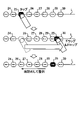
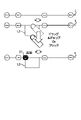
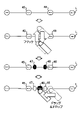
- the user may draw an arc so as to surround the control element 40 corresponding to the process to be repeatedly executed, as shown in FIG. As a result, an arc straddling the line L is drawn at least once.
- the repeat element 41 and the repeat element 42 are lined as new control elements. Add on L.
- the repeating element 41 and the repeating element 42 are added in front of and behind the control element 40 so as to sandwich the control element 40 indicating the process to be repeated.
- the parameter setting for the repeating element can be performed by tapping or long tapping the repeating element 41 added on the line L. This point is the same as the case where the parameter is set for an arbitrary control element as described above in FIG. The number of iterations can be set in the setting window 43. Further, by setting the parameter "Block" to ON, as shown in FIG. 15, the iterative element (repetitive element 41, iterative element 42) and the control element 40 corresponding to the process to be repeatedly executed are combined into one element. Can be blocked into.
- the positions of the start and end of the arc are not particularly limited.
- an arc may be drawn from the region above the line L to the region below the line L, and as shown in FIG. 16, the region below the line L passes through the region above the line L. You may draw an arc down to the lower area.
- an arc may be drawn from the region above the line L to the region above the region L through the region below the line L.
- the user can add a repeating element only by performing an input operation so that the trajectory of the input operation draws an arc straddling the line.
- the operation of drawing an arc in which the trajectory straddles the line is an operation that is easily recalled when imagining the repetition in which the processing is repeated, and even a beginner can intuitively grasp and remember it as an operation for the iterative processing. Easy to remain. Therefore, according to the information processing apparatus 10, a more complicated program using repetitive elements can be easily assembled by intuitive operation without interrupting thinking.
- FIGS. 17 and 18 are diagrams for explaining yet another example of the method of adding an element indicating repetition.
- an example of adding a repeating element when the locus of the detected input operation draws an arc straddling the line L has been shown, but in the following, the detected input operation is performed with reference to FIGS. 17 and 18.
- An example of adding a repeating element to a line L or an element on the line L in a bidirectional operation in a direction intersecting the line L will be described.
- the user may flick up and down on the left and right of the control element 40 corresponding to the process to be repeatedly executed, as shown in FIG. Further, as shown in FIG. 18, flicking may be performed up and down at the same position with respect to the line L.
- flicking up and down at the same position as shown in FIG. 18, since there is no control element between the added repeating elements (repeating element 41, repeating element 42), after the repeating element is added, The desired control element (control element 46) may be moved between repeating elements by dragging and dropping.
- a set of flicks may be performed in the order of up and down or in the order of bottom and top.
- the user can add a repeating element only by performing a bidirectional operation in a direction intersecting the line.
- Bidirectional operation in the direction of crossing the line is an operation that is easy to recall when imagining an iteration in which the process is repeated, and even a beginner can intuitively grasp and remember it as an operation for iterative processing. Easy to remain. Therefore, according to the information processing apparatus 10, a more complicated program using repetitive elements can be easily assembled by intuitive operation without interrupting thinking.
- FIG. 19 is a diagram for explaining an example of an operation method for elements showing iterations created in a nested manner.
- FIG. 15 shows an example of blocking an iterative element and a control element corresponding to a process to be repeatedly executed into one element.
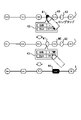
- the target to be blocked together with the iterative element is It may be a control element (control element 52), or may include a block of a control element and a repeating element (element 56).
- the element 56 in which the elements 51 to the element 53 are blocked can be displayed with an arbitrary name
- the element 57 in which the element 59 to the element 55 is blocked can also be similarly given an arbitrary name. It is possible to display with. By changing the name of the blocked element to an appropriate name indicating the processing content, the processing content performed by that element can be recognized at a glance.
- the information processing device 10 having a built-in touch panel display is illustrated, but the information processing device that executes a program to realize the modeling support as described above is connected to the touch panel display by wire or wirelessly.
- the touch panel display may be a desktop computer.
- the input device 3 is a touch sensor constituting the touch panel has been described as an example, but the input device 3 does not necessarily have to be a touch sensor.
- an information processing device including a keyboard as an input device will be described.
- FIG. 20 is an external view of the information processing apparatus 60 according to the present embodiment.
- the information processing apparatus 60 is, for example, a laptop computer in which a program for visual programming is installed.
- the information processing device 60 includes a display device 61 and an input device 62.
- the information processing device 60 is different from the information processing device 10 in that the display device 61 is not a touch panel display but the input device 62 is a keyboard. That is, the information processing device 60 differs from the information processing device 10 in that visual programming is performed by operating the keyboard, but other configurations include, for example, one or more processors and one or more storage devices 2.
- the points to be provided are the same as those of the information processing apparatus 10.
- FIG. 21 is a diagram for explaining an example of a method of adding an element indicating a branch.
- FIG. 22 is a diagram for explaining an example of a method of adding an element indicating repetition.
- any control element including branching and repetition can be added to the program by a simple operation.
- a method of adding a branching element and a repeating element to the region 12 will be described with reference to FIGS. 21 and 22.
- the user When adding a branch element, as shown in FIG. 21, the user first selects a control element corresponding to the process to be executed only under specific conditions by using the cross key 80 and the selection key 90. For example, if it is desired to execute the process corresponding to the control element 72 only under specific conditions, the cursor 70 is moved from the control element 71 to the control element 72 with the right key of the cross key 80, and further, the selection key 90 is used. Press the enter key to select the control element 72.
- a branch element is added using the cross key 80.
- the down key of the cross key 80 is pressed.
- a new line L1 branched from the line L is added, the control element 72 is displayed on the line L1, and a new control is performed at the branch point branching from the line L to the line L1.
- a branch element 73 is added as an element.
- FIG. 21 shows an example of adding a branch element with the lower key
- the branch element may be added by pressing the upper key. That is, one-way operation in the direction intersecting the line L may be performed.
- the user when adding an iterative element, as shown in FIG. 22, the user first selects a control element corresponding to the process to be repeatedly executed by using the cross key 80 and the selection key 90. For example, if it is desired to repeatedly execute the process corresponding to the control element 72, move the cursor 70 from the control element 71 to the control element 72 with the right key of the cross key 80, and further press the enter key of the selection key 90. And select the control element 72.
- a repeating element using the cross key 80 For example, the up and down keys of the cross key 80 are pressed in order. As a result, as shown in FIG. 22, a repeating element 74 and a repeating element 75 are added on the line L as new control elements. The repeating element 74 and the repeating element 75 are added in front of and behind the control element 72 so as to sandwich the control element 72 indicating the process to be repeated.
- FIG. 22 shows an example in which the up key and the down key are pressed in this order
- the repeating element may be added by pressing the down key and the up key in this order. That is, bidirectional operation in the direction intersecting the line L may be performed.
- the information processing apparatus 60 can also add a control structure classified into branching and repetition to the program by an intuitive and simple operation.
- Appendix 2 In the modeling support method described in Appendix 1, The process of displaying the new element on the display device is the branching on the line when the detected input operation is a one-way operation in a direction intersecting the line with respect to the line or the element on the line. A modeling support method comprising a process of displaying the new element indicating a control structure classified into the above on the display device.
- Appendix 3 In the modeling support method described in Appendix 1 or Appendix 2, The process of displaying the new element on the display device is the repetition on the line when the detected input operation is a bidirectional operation in a direction intersecting the line with respect to the line or the element on the line.
- a modeling support method comprising a process of displaying the new element indicating a control structure classified into the above on the display device.
- Appendix 4 In the modeling support method described in any one of Supplementary Note 1 to Supplementary Note 3, The modeling support method, wherein the computer detects the input operation based on an output from a touch sensor that detects the input operation to the display device.
- Appendix 5 In the modeling support method described in Appendix 4, In the process of displaying the new element on the display device, when the detected trajectory of the input operation draws an arc straddling the line, the new element showing the control structure classified into the iteration is displayed on the line.
- a modeling support method comprising a process of displaying on the display device.
- One or more non-temporary computer-readable media containing instructions Includes one or more processors that execute the instructions.
- the instruction is configured to cause the one or more processors to perform an operation.
- the above operation is Displaying on the display device a line on which one or more elements can be placed indicating a control structure, each of which is classified as sequential, branching, or repeating.
- the display device may display a new element indicating a control structure classified into the branch or the iteration on the line.
- An information processing device characterized by including.
- Processor 2 Memory 2a Program 3, 62 Input device 4, 61 Display device 10, 60 Information processing device 21, 22, 24-31, 34-36, 40, 45, 46, 52, 54, 71, 72 Control element 32 , 37-39, 73 Branching element 41, 42, 47-49, 51, 53, 55, 74, 75 Repeating element 44, 50, 56, 57 element L, L1-L3 line
Landscapes
- Engineering & Computer Science (AREA)
- General Engineering & Computer Science (AREA)
- Theoretical Computer Science (AREA)
- Physics & Mathematics (AREA)
- General Physics & Mathematics (AREA)
- Human Computer Interaction (AREA)
- Software Systems (AREA)
- User Interface Of Digital Computer (AREA)
- Stored Programmes (AREA)
Applications Claiming Priority (2)
| Application Number | Priority Date | Filing Date | Title |
|---|---|---|---|
| JP2020-210086 | 2020-12-18 | ||
| JP2020210086A JP7219868B2 (ja) | 2020-12-18 | 2020-12-18 | モデリング支援方法、情報処理装置、及び、プログラム |
Publications (1)
| Publication Number | Publication Date |
|---|---|
| WO2022130943A1 true WO2022130943A1 (ja) | 2022-06-23 |
Family
ID=82059047
Family Applications (1)
| Application Number | Title | Priority Date | Filing Date |
|---|---|---|---|
| PCT/JP2021/043501 Ceased WO2022130943A1 (ja) | 2020-12-18 | 2021-11-26 | モデリング支援方法、情報処理装置、及び、プログラム |
Country Status (2)
| Country | Link |
|---|---|
| JP (3) | JP7219868B2 (enExample) |
| WO (1) | WO2022130943A1 (enExample) |
Families Citing this family (1)
| Publication number | Priority date | Publication date | Assignee | Title |
|---|---|---|---|---|
| JP2024164701A (ja) * | 2023-05-15 | 2024-11-27 | パナソニックIpマネジメント株式会社 | モデリング装置、モデリング方法及びプログラム |
Citations (1)
| Publication number | Priority date | Publication date | Assignee | Title |
|---|---|---|---|---|
| JP2011048477A (ja) * | 2009-08-25 | 2011-03-10 | Justsystems Corp | フローチャート描画装置、フローチャート描画方法およびフローチャート描画プログラム |
Family Cites Families (17)
| Publication number | Priority date | Publication date | Assignee | Title |
|---|---|---|---|---|
| JPH0756725A (ja) * | 1993-06-30 | 1995-03-03 | Hitachi Ltd | プログラム作成支援方法 |
| JPH07320080A (ja) * | 1994-05-23 | 1995-12-08 | Matsushita Electric Ind Co Ltd | 図形編集装置 |
| JPH1139145A (ja) * | 1997-07-24 | 1999-02-12 | Casio Comput Co Ltd | プログラム構築支援装置及び記憶媒体 |
| JP3953738B2 (ja) * | 2000-01-31 | 2007-08-08 | 富士通株式会社 | 図形編集装置、および図形編集装置として機能させるためのプログラムを格納した記録媒体 |
| CN1558738A (zh) | 2001-11-22 | 2004-12-29 | ��ʽ���綫֥ | 超声波诊断设备、工作流程编辑系统和控制超声波诊断设备的方法 |
| JP2005309593A (ja) * | 2004-04-19 | 2005-11-04 | Mitsubishi Electric Corp | プログラム作成装置及びプログラム作成方法 |
| GB0426247D0 (en) * | 2004-11-25 | 2004-12-29 | Koninkl Philips Electronics Nv | User interface for content authoring |
| JP5074896B2 (ja) | 2007-11-16 | 2012-11-14 | 株式会社キーエンス | 検査支援システム及び画像処理コントローラ |
| CN101650798B (zh) * | 2009-09-14 | 2012-03-21 | 中国科学院计算技术研究所 | 流程建模方法 |
| KR101260834B1 (ko) * | 2010-12-14 | 2013-05-06 | 삼성전자주식회사 | 타임라인 바를 이용한 터치스크린 제어방법, 장치 및 이를 위한 프로그램이 기록된 기록매체 및 사용자 단말 |
| JP5921703B2 (ja) | 2012-10-16 | 2016-05-24 | 三菱電機株式会社 | 情報表示装置および情報表示装置における操作制御方法 |
| JP5818172B2 (ja) * | 2013-06-21 | 2015-11-18 | コニカミノルタ株式会社 | 情報表示装置及び表示制御プログラム並びに表示制御方法 |
| JP2016115017A (ja) * | 2014-12-12 | 2016-06-23 | 日本電信電話株式会社 | フローチャート作成方法及びプログラム |
| JP2016115191A (ja) * | 2014-12-16 | 2016-06-23 | コニカミノルタ株式会社 | 会議支援装置、会議支援システム、会議支援方法、及び会議支援プログラム |
| JP6350261B2 (ja) | 2014-12-17 | 2018-07-04 | コニカミノルタ株式会社 | オブジェクト操作システム及びオブジェクト操作制御プログラム並びにオブジェクト操作制御方法 |
| US9639184B2 (en) * | 2015-03-19 | 2017-05-02 | Apple Inc. | Touch input cursor manipulation |
| JP6606028B2 (ja) * | 2016-07-11 | 2019-11-13 | 株式会社東芝 | 文書不備検出プログラム、文書不備検出装置および文書不備検出方法 |
-
2020
- 2020-12-18 JP JP2020210086A patent/JP7219868B2/ja active Active
-
2021
- 2021-11-26 WO PCT/JP2021/043501 patent/WO2022130943A1/ja not_active Ceased
-
2023
- 2023-01-19 JP JP2023006264A patent/JP7661985B2/ja active Active
-
2025
- 2025-03-21 JP JP2025046164A patent/JP7831665B2/ja active Active
Patent Citations (1)
| Publication number | Priority date | Publication date | Assignee | Title |
|---|---|---|---|---|
| JP2011048477A (ja) * | 2009-08-25 | 2011-03-10 | Justsystems Corp | フローチャート描画装置、フローチャート描画方法およびフローチャート描画プログラム |
Also Published As
| Publication number | Publication date |
|---|---|
| JP2025090844A (ja) | 2025-06-17 |
| JP7219868B2 (ja) | 2023-02-09 |
| JP7661985B2 (ja) | 2025-04-15 |
| JP2023054806A (ja) | 2023-04-14 |
| JP2022096859A (ja) | 2022-06-30 |
| JP7831665B2 (ja) | 2026-03-17 |
Similar Documents
| Publication | Publication Date | Title |
|---|---|---|
| JP6071107B2 (ja) | 携帯端末 | |
| ES2939305T3 (es) | Navegación entre actividades en un dispositivo informático | |
| JP4981701B2 (ja) | 端末機のタッチスクリーンを用いる文字入力装置及び方法 | |
| KR101686581B1 (ko) | 툴바 탐색(Toolbar Navigation)을 위한 사용자 인터페이스(User Interface) | |
| US9195387B2 (en) | Separating a cursor when a touch selection continues from a first to second screen | |
| JP2012133745A (ja) | 情報処理装置およびその表示サイズ制御方法 | |
| EP3278203B1 (en) | Enhancement to text selection controls | |
| JP6041742B2 (ja) | タッチパネル表示制御装置 | |
| JP7831665B2 (ja) | モデリング支援方法、情報処理装置、及び、プログラム | |
| JP2012226516A (ja) | 電子機器、表示制御方法及びプログラム | |
| JP2013196100A (ja) | 図面表示装置、及び図面表示プログラム | |
| JP5747688B2 (ja) | 計算装置およびプログラム | |
| JP2018101054A (ja) | 表示装置、表示方法及びプログラム | |
| JP2017016594A (ja) | 情報処理装置、情報表示プログラムおよび情報表示方法 | |
| JP6369937B2 (ja) | アイコン表示装置及びアイコン表示プログラム | |
| JP2013182342A (ja) | 入力装置、入力装置の制御方法、制御プログラム、および記録媒体 | |
| JP5304849B2 (ja) | 電子機器およびプログラム | |
| KR101050671B1 (ko) | 터치스크린을 이용한 한글 입력 장치, 그 방법 | |
| JP2017027190A (ja) | オブジェクト操作制御プログラム及びオブジェクト操作制御方法並びにオブジェクト操作システム | |
| JP5742870B2 (ja) | 電子機器およびプログラム | |
| JP7215054B2 (ja) | プログラミング表示装置、プログラミング表示方法、およびプログラム | |
| CN108205407B (zh) | 显示装置、显示方法及存储介质 | |
| JP6194383B2 (ja) | 情報処理装置、情報表示プログラムおよび情報表示方法 | |
| KR20220053522A (ko) | 터치스크린 상에서 터치 버튼의 멀티터치 인식방법, 문자 입력 방법 및 객체 변형 방법 | |
| KR20220064937A (ko) | 터치스크린 상에서 터치 버튼의 멀티터치 인식방법, 문자 입력 방법 및 객체 변형 방법 |
Legal Events
| Date | Code | Title | Description |
|---|---|---|---|
| 121 | Ep: the epo has been informed by wipo that ep was designated in this application |
Ref document number: 21906306 Country of ref document: EP Kind code of ref document: A1 |
|
| NENP | Non-entry into the national phase |
Ref country code: DE |
|
| 122 | Ep: pct application non-entry in european phase |
Ref document number: 21906306 Country of ref document: EP Kind code of ref document: A1 |