WO2022113570A1 - タービン - Google Patents
タービン Download PDFInfo
- Publication number
- WO2022113570A1 WO2022113570A1 PCT/JP2021/038576 JP2021038576W WO2022113570A1 WO 2022113570 A1 WO2022113570 A1 WO 2022113570A1 JP 2021038576 W JP2021038576 W JP 2021038576W WO 2022113570 A1 WO2022113570 A1 WO 2022113570A1
- Authority
- WO
- WIPO (PCT)
- Prior art keywords
- inner peripheral
- rotor
- stationary blade
- axial direction
- radial direction
- Prior art date
- Legal status (The legal status is an assumption and is not a legal conclusion. Google has not performed a legal analysis and makes no representation as to the accuracy of the status listed.)
- Ceased
Links
Images




Classifications
-
- F—MECHANICAL ENGINEERING; LIGHTING; HEATING; WEAPONS; BLASTING
- F01—MACHINES OR ENGINES IN GENERAL; ENGINE PLANTS IN GENERAL; STEAM ENGINES
- F01D—NON-POSITIVE DISPLACEMENT MACHINES OR ENGINES, e.g. STEAM TURBINES
- F01D11/00—Preventing or minimising internal leakage of working-fluid, e.g. between stages
- F01D11/001—Preventing or minimising internal leakage of working-fluid, e.g. between stages for sealing space between stator blade and rotor
-
- F—MECHANICAL ENGINEERING; LIGHTING; HEATING; WEAPONS; BLASTING
- F01—MACHINES OR ENGINES IN GENERAL; ENGINE PLANTS IN GENERAL; STEAM ENGINES
- F01D—NON-POSITIVE DISPLACEMENT MACHINES OR ENGINES, e.g. STEAM TURBINES
- F01D11/00—Preventing or minimising internal leakage of working-fluid, e.g. between stages
- F01D11/08—Preventing or minimising internal leakage of working-fluid, e.g. between stages for sealing space between rotor blade tips and stator
-
- F—MECHANICAL ENGINEERING; LIGHTING; HEATING; WEAPONS; BLASTING
- F01—MACHINES OR ENGINES IN GENERAL; ENGINE PLANTS IN GENERAL; STEAM ENGINES
- F01D—NON-POSITIVE DISPLACEMENT MACHINES OR ENGINES, e.g. STEAM TURBINES
- F01D11/00—Preventing or minimising internal leakage of working-fluid, e.g. between stages
- F01D11/02—Preventing or minimising internal leakage of working-fluid, e.g. between stages by non-contact sealings, e.g. of labyrinth type
-
- F—MECHANICAL ENGINEERING; LIGHTING; HEATING; WEAPONS; BLASTING
- F01—MACHINES OR ENGINES IN GENERAL; ENGINE PLANTS IN GENERAL; STEAM ENGINES
- F01D—NON-POSITIVE DISPLACEMENT MACHINES OR ENGINES, e.g. STEAM TURBINES
- F01D9/00—Stators
- F01D9/02—Nozzles; Nozzle boxes; Stator blades; Guide conduits, e.g. individual nozzles
- F01D9/04—Nozzles; Nozzle boxes; Stator blades; Guide conduits, e.g. individual nozzles forming ring or sector
-
- F—MECHANICAL ENGINEERING; LIGHTING; HEATING; WEAPONS; BLASTING
- F01—MACHINES OR ENGINES IN GENERAL; ENGINE PLANTS IN GENERAL; STEAM ENGINES
- F01D—NON-POSITIVE DISPLACEMENT MACHINES OR ENGINES, e.g. STEAM TURBINES
- F01D9/00—Stators
- F01D9/02—Nozzles; Nozzle boxes; Stator blades; Guide conduits, e.g. individual nozzles
- F01D9/04—Nozzles; Nozzle boxes; Stator blades; Guide conduits, e.g. individual nozzles forming ring or sector
- F01D9/041—Nozzles; Nozzle boxes; Stator blades; Guide conduits, e.g. individual nozzles forming ring or sector using blades
-
- F—MECHANICAL ENGINEERING; LIGHTING; HEATING; WEAPONS; BLASTING
- F04—POSITIVE - DISPLACEMENT MACHINES FOR LIQUIDS; PUMPS FOR LIQUIDS OR ELASTIC FLUIDS
- F04D—NON-POSITIVE-DISPLACEMENT PUMPS
- F04D29/00—Details, component parts, or accessories
- F04D29/66—Combating cavitation, whirls, noise, vibration or the like; Balancing
- F04D29/68—Combating cavitation, whirls, noise, vibration or the like; Balancing by influencing boundary layers
-
- F—MECHANICAL ENGINEERING; LIGHTING; HEATING; WEAPONS; BLASTING
- F04—POSITIVE - DISPLACEMENT MACHINES FOR LIQUIDS; PUMPS FOR LIQUIDS OR ELASTIC FLUIDS
- F04D—NON-POSITIVE-DISPLACEMENT PUMPS
- F04D19/00—Axial-flow pumps
-
- F—MECHANICAL ENGINEERING; LIGHTING; HEATING; WEAPONS; BLASTING
- F05—INDEXING SCHEMES RELATING TO ENGINES OR PUMPS IN VARIOUS SUBCLASSES OF CLASSES F01-F04
- F05D—INDEXING SCHEME FOR ASPECTS RELATING TO NON-POSITIVE-DISPLACEMENT MACHINES OR ENGINES, GAS-TURBINES OR JET-PROPULSION PLANTS
- F05D2220/00—Application
- F05D2220/30—Application in turbines
- F05D2220/31—Application in turbines in steam turbines
Definitions
- the present disclosure relates to turbines.
- the present application claims priority with respect to Japanese Patent Application No. 2020-195481 filed in Japan on November 25, 2020, the contents of which are incorporated herein by reference.
- Gas turbines and steam turbines mainly include a rotor that rotates around an axis, a casing that covers the rotor from the outer peripheral side, and a plurality of stationary blade stages provided on the inner peripheral side of the casing (the following patents). See Document 1).
- the rotor has a rotor body extending along an axis and a plurality of blade stages arranged on the outer peripheral surface of the rotor body.
- the stationary blade stage and the moving blade stage are arranged alternately in the axial direction.
- the stationary blade stage has a plurality of stationary blades arranged in the circumferential direction.
- the blade stage has a plurality of blades arranged in the circumferential direction.
- the fluid guided from the outside flows into the rotor blade stage after the flow direction is changed by the blade stage. As a result, steam energy is converted into rotational force through the blade stage, and the rotor rotates.
- the present disclosure has been made to solve the above problems, and an object of the present disclosure is to provide a steam turbine with further improved efficiency.
- the steam turbine according to the present disclosure includes a rotor body that can rotate around an axis, and a rotor having a plurality of moving blades arranged in a circumferential direction along the outer peripheral surface of the rotor body.
- a casing covering the rotor and a plurality of stationary blades arranged in the circumferential direction along the inner peripheral surface of the casing are provided, and the stationary blades extend radially with respect to the axis and one of the axial directions.
- a stationary wing body having a suction portion formed on the surface capable of sucking at least a part of a working fluid flowing from one side to the other side, a nozzle inner peripheral member provided radially inside the stationary wing body, and the like.
- It has a plurality of seal fins that protrude inward in the radial direction from the inner peripheral surface of the nozzle inner peripheral member and are arranged at intervals in the axial direction, and have the nozzle inner peripheral member and the seal fin.
- a nozzle for ejecting a working fluid guided from the suction portion is formed in a portion on the other side of the seal fin on the most one side in the axial direction.
- FIG. 1 It is a schematic diagram which shows the structure of the steam turbine which concerns on 1st Embodiment of this disclosure. It is an enlarged sectional view of the main part of the steam turbine which concerns on 1st Embodiment of this disclosure. It is a perspective view of the stationary wing which concerns on 1st Embodiment of this disclosure. It is an enlarged sectional view of the seal fin which concerns on 1st Embodiment of this disclosure. It is a perspective view which shows the 1st modification of the stationary wing which concerns on 1st Embodiment of this disclosure. It is a perspective view which shows the 2nd modification of the stationary wing which concerns on 1st Embodiment of this disclosure.
- the steam turbine 1 (turbine) according to the first embodiment of the present disclosure will be described with reference to FIGS. 1 to 4.
- the steam turbine 1 includes a rotor 2, a casing 3, a vane stage 9, a journal bearing 4, and a thrust bearing 5.
- the rotor 2 has a rotor body 6 extending along the axis Ac, and a plurality of blade stages 7 arranged at intervals in the axis Ac direction on the outer peripheral surface of the rotor body 6.
- One journal bearing 4 is provided at both ends of the rotor main body 6 in the axial direction Ac direction.
- the journal bearing 4 rotatably supports the rotor body 6 around the axis Ac while supporting the radial load of the rotor body 6.
- One thrust bearing 5 is provided on one side of the rotor body 6 in the Ac direction of the axis. The thrust bearing 5 supports the load in the axial direction Ac direction by the rotor main body 6.
- Each rotor blade stage 7 has a plurality of rotor blades 8 arranged in the circumferential direction along the outer peripheral surface of the rotor main body 6.
- Each rotor blade 8 has an airfoil cross-sectional shape with one side in the axis Ac direction as the leading edge and the other side as the trailing edge when viewed from the radial direction.
- the casing 3 has a cylindrical shape that covers the rotor 2 from the outside.
- a plurality of stationary blade stages 9 arranged at intervals in the axis Ac direction are provided on the inner peripheral surface of the casing 3. These blade stages 9 are arranged alternately with the blade stages 7 in the axial direction Ac. More specifically, one stationary blade stage 9 is provided on one side of each blade stage 7 in the axis Ac direction.
- Each stationary blade stage 9 has a plurality of stationary blades 10 arranged in the circumferential direction along the inner peripheral surface of the casing 3.
- the stationary blade 10 has an airfoil cross-sectional shape having a leading edge on one side in the Ac direction of the axis and a trailing edge on the other side when viewed from the radial direction.
- a steam supply port 40 for guiding steam generated outside is provided on one side of the casing 3 in the Ac direction.
- the steam guided into the casing 3 through the steam supply port 40 collides with the rotor blade stage 7 after the flow direction is changed by the above-mentioned stationary blade stage 9.
- rotational energy around the axis Ac is applied to the rotor 2 via the blade stage 7.
- a steam discharge port 50 for discharging steam that has passed through the inside of the casing 3 is provided on the other side of the casing 3 in the direction of the axis Ac.
- the side where the steam supply port 40 is located (that is, one side in the axis Ac direction) as viewed from the steam discharge port 50 is simply referred to as the "upstream side", and the opposite side is simply referred to as the "downstream side”. There is.
- the stationary blade 10 has a nozzle outer peripheral member 31, a stationary blade main body 11, a nozzle inner peripheral member 12, and a stationary blade seal fin 13 (seal fin).
- the nozzle outer peripheral member 31 is attached to the inner peripheral surface 3S of the casing 3.
- the nozzle outer peripheral member 31 has an annular shape centered on the axis line Ac.
- the stationary blade main body 11 extends radially inward from the nozzle outer peripheral member 31. That is, the nozzle outer peripheral member 31 supports a plurality of stationary blade main bodies 11 arranged in the circumferential direction from the outside in the radial direction.
- the upstream end edge of the stationary blade main body 11 is a leading edge 11L
- the downstream end edge is a trailing edge 11T.
- the curve connecting the leading edge 11L and the trailing edge 11T (that is, the line passing through the center in the airfoil cross section) is defined as the camber line CL.
- the surface facing one side in the circumferential direction with the camber line CL as a boundary is a positive pressure surface 11A
- the surface facing the other side is a negative pressure surface 11B.
- the positive pressure surface 11A is recessed in a curved surface toward the other side in the circumferential direction.
- the positive pressure surface 11A faces the upstream side in the steam flow direction.
- the negative pressure surface 11B projects in a curved surface toward the other side in the circumferential direction.
- the negative pressure surface 11B faces the downstream side in the steam flow direction.
- the negative pressure surface 11B is formed with a suction portion 20 capable of sucking at least a part of steam (working fluid) flowing around the stationary blade main body 11.
- the suction portion 20 has a pair of leading edge side suction ports 21 formed at positions biased toward the front edge 11L side, and one trailing edge side suction port 22 formed at positions biased toward the trailing edge 11T side. ing.
- the front edge side suction port 21 is a rectangular opening whose longitudinal direction is the radial direction.
- the front edge side suction port 21 may be circular or elliptical.
- the pair of front edge side suction ports 21 are separated from each other in the radial direction.
- One front edge side suction port 21 is formed in the vicinity of the radial outer end portion of the negative pressure surface 11B, and the other front edge side suction port 21 is formed in the vicinity of the radial inner end portion.
- the distance from the radial end of the stationary blade main body 11 to the front edge side suction port 21 is smaller than the distance between the pair of front edge side suction ports 21.
- the positions of the pair of front edge side suction ports 21 in the axial line Ac direction are the same as each other.
- the trailing edge side suction port 22 is a rectangular opening whose longitudinal direction is the radial direction. Unlike the front edge side suction port 21 described above, the trailing edge side suction port 22 extends over almost the entire radial direction on the negative pressure surface 11B. That is, the rear edge side suction port 22 has a larger radial dimension than the front edge side suction port 21.
- the radial position of the radial outer end of the trailing edge side suction port 22 is the same as the radial position of the radial outer end of one (diametrically outer) front edge side suction port 21. Further, the radial position of the radial inner end of the trailing edge side suction port 22 is the same as the radial position of the radial inner end portion of the other (diametrically inner) front edge side suction port 21.
- the inside of the stationary blade main body 11 is hollow, and the above-mentioned suction portion 20 (front edge side suction port 21 and rear edge side suction port 22) communicates with the ejection port H described later through this hollow portion. .. More specifically, a flow path through which the fluid flows is formed inside the stationary blade main body 11, and the suction portion 20 communicates with the ejection port H through this flow path.
- a nozzle inner peripheral member 12 is provided inside the stationary blade body 11 in the radial direction.
- the nozzle inner peripheral member 12 forms an annular shape centered on the axis Ac, and supports a plurality of stationary blade main bodies 11 arranged in the circumferential direction from the inside in the radial direction.
- the inner peripheral surface 12S of the nozzle inner peripheral member 12 faces the outer peripheral surface 6S of the rotor main body 6 with a radial interval.
- a plurality of stationary blade seal fins 13 are provided on the inner peripheral surface 12S.
- three stationary blade seal fins 13 are arranged at intervals in the axis Ac direction.
- the number of stationary blade seal fins 13 is not limited to three, and may be four or more.
- Each of the stationary blade seal fins 13 has an annular shape that protrudes inward in the radial direction from the inner peripheral surface 12S and extends in the circumferential direction.
- the stationary blade seal fin 13 has a tapered cross-sectional shape as the dimension in the axis Ac direction gradually decreases from the outer side in the radial direction to the inner side. A certain clearance is formed between the radial inner end of the vane seal fin 13 and the outer peripheral surface 6S of the rotor body 6.
- the stationary blade seal fin 13 located on the most upstream side is designated as the first seal fin 13A, and the stationary blade seal fin 13 located on the most downstream side is used.
- 13 be the third seal fin 13C.
- the stationary blade seal fin 13 located between the first seal fin 13A and the third seal fin 13C is referred to as a second seal fin 13B.
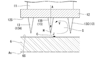
- a spout H communicating with the suction portion 20 described above is formed at the tip (diameter inner end) of the second seal fin 13B. That is, although not shown in detail, a flow path for communicating the suction portion 20 and the ejection port H is formed inside the second seal fin 13B.
- the main flow of steam that is, the flow of steam flowing around the stationary blade main body 11
- the static pressure is lower than that around the stationary blade body 11. That is, a pressure difference is generated between the space S and the periphery of the stationary blade main body 11.
- the rotor blade 8 has a disk 61, a rotor blade main body 81, an outer shroud 82, and a rotor blade seal fin 83.
- the disk 61 forms an annular shape centered on the axis Ac, and is attached to the outer peripheral surface 6S of the rotor main body 6.
- a plurality of rotor blade bodies 81 are provided on the outer peripheral side of the disk 61. These blade bodies 81 are arranged at intervals in the circumferential direction.
- each rotor blade body 81 has an airfoil-shaped cross-sectional shape when viewed from the radial direction.
- An outer shroud 82 is provided on the radial outer side of the rotor blade body 81.
- the outer shroud 82 forms an annular shape centered on the axis Ac, and supports a plurality of blade bodies 81 from the outside in the radial direction.
- the outer peripheral surface 82S of the outer shroud 82 is provided with a plurality of blade seal fins 83 arranged at intervals in the axis Ac direction.
- the rotor blade seal fin 83 suppresses the flow (leakage flow) of steam flowing between the outer shroud 82 and the inner peripheral surface 3S.
- four rotor blade seal fins 83 are provided as an example.
- the number of rotor blade seal fins 83 is not limited to four, and may be three or less or five or more.
- Each blade seal fin 83 has an annular shape that protrudes radially outward from the outer peripheral surface 82S and extends in the circumferential direction.
- the rotor blade seal fin 83 has a tapered cross-sectional shape as the dimension in the axis Ac direction gradually decreases from the inside to the outside in the radial direction. A certain gap (clearance) is formed between the tip of the rotor blade seal fin 83 (the end portion on the outer side in the radial direction) and the inner peripheral surface 3S of the casing 3.
- the rotational energy of the rotor 2 is used, for example, to drive a generator (not shown) connected to the shaft end.
- the steam that has passed through the most downstream rotor blade stage 7 is guided to an external condenser or the like (not shown) through the steam discharge port 50.
- the boundary layer and the secondary flow are sucked through the suction portion 20 described above, and the jet jet H is supplied as the jet flow J to the space S between the stationary blade seal fins 13.
- the static pressure is lower than the region (main flow path) in which the main stream of steam flows.
- a flow from the suction portion 20 formed on the surface of the stationary blade main body 11 toward the ejection port H is formed.
- the boundary layer and steam as a secondary flow are sucked from the suction unit 20.
- the steam sucked from the suction unit 20 is ejected into the space S between the stationary blade seal fins 13 through the ejection port H.
- the boundary layer and secondary flow formed on the surface of the stationary blade body 11 are reduced.
- the efficiency of the steam turbine 1 can be further improved.
- the boundary layer and the secondary flow tend to be formed particularly easily on the negative pressure surface 11B side of the stationary blade main body 11.
- the suction portion 20 is formed on the negative pressure surface 11B side with respect to the leading edge 11L of the stationary blade main body 11.
- the boundary layer and the secondary flow can be sucked in more effectively, and the energy loss can be further reduced.
- since the opening as the suction portion 20 is formed only on the negative pressure surface 11B, it is quieter than the case where the same opening is formed on the positive pressure surface 11A, for example. It is also possible to avoid a decrease in the strength of the wing body 11.
- the boundary layer tends to develop particularly easily at the position of the negative pressure surface 11B that is biased toward the trailing edge 11T.
- the trailing edge side suction port 22 is formed at a position where the boundary layer is likely to develop. Since the boundary layer is sucked through the trailing edge side suction port 22, the steam flow is in a state of being closely adhered to the negative pressure surface 11B. As a result, the flow of steam is smoothed, and the energy loss of the steam turbine 1 can be further reduced.
- the front edge side suction port 21 is formed at a position where a secondary flow is likely to occur. Since the secondary flow is sucked through the front edge side suction port 21, the steam flow is in a state of being more closely adhered to the negative pressure surface 11B. As a result, the energy loss of the steam turbine 1 can be further suppressed.
- a vortex V is formed by a leak flow flowing from the clearance C between the stationary blade seal fin 13 and the outer peripheral surface 6S of the rotor main body 6.
- the vortex V flows from the upstream side to the downstream side along the outer peripheral surface 6S, then turns radially outward along the stationary blade seal fin 13 on the downstream side, and further, the inner peripheral surface 12S of the nozzle inner peripheral member 12 It flows toward the upstream side again along.
- the ejection port H is formed at the inner end in the radial direction of the second seal fin 13B, which is the second one counting from one side in the axis Ac direction.
- the jet flow J ejected from the jet outlet H obstructs the leak flow flowing through the clearance C, and can give a contraction effect to the leak flow.
- a further turning force is applied to the above-mentioned vortex V by the jet flow J.
- the development of the vortex V makes it possible to further reduce the flow rate of the leak flow flowing into the space S.
- the efficiency of the steam turbine 1 can be further improved by improving the sealing performance by the stationary blade seal fin 13.
- the first embodiment of the present disclosure has been described above. It is possible to make various changes and modifications to the above configuration as long as it does not deviate from the gist of the present disclosure.
- a configuration in which a pair of front edge side suction ports 21 are provided apart in the radial direction has been described.
- FIG. 5 it is also possible to form only one front edge side suction port 21B extending over the entire radial direction. According to this configuration, since the front edge side suction port 21 is formed over the entire area in the radial direction, the secondary flow can be efficiently sucked in a wider range.
- FIG. 6 it is also possible to adopt a configuration in which only the trailing edge side suction port 22 is formed without forming the front edge side suction port 21.
- the opening formed in the stationary blade main body 11 can be reduced by the amount that the front edge side suction port 21 is not formed, so that the strength reduction of the stationary blade main body 11 is minimized while reducing the boundary layer. Can be suppressed to.
- FIG. 7 it is possible to adopt a configuration in which only the front edge side suction port 21 is formed without forming the trailing edge side suction port 22. According to this configuration, the secondary flow and the boundary layer can be sucked and reduced at the same time by the front edge side suction port 21. Further, in this case as well, since the opening formed in the stationary blade main body 11 can be reduced, it is possible to minimize the decrease in the strength of the stationary blade main body 11 while reducing the secondary flow and the boundary layer.
- the spout H1 is open on the inner peripheral surface 12S of the nozzle inner peripheral member 12. More specifically, the spout H1 opens toward the space S between the first seal fin 13A and the second seal fin 13B. More specifically, the ejection port H1 is formed at a position biased toward the first seal fin 13A in the space S in the axis Ac direction. That is, it is possible to promote the turning force of the vortex V by forming the jet flow J along the flow direction of the vortex V formed in the space S.
- This ejection port H1 communicates with the suction portion 20 described in the first embodiment through the flow path F.
- the flow path F penetrates the nozzle inner peripheral member 12 in the radial direction.
- steam can be supplied to the region (space S) between the adjacent stationary blade seal fins 13 through the ejection port H1 formed on the inner peripheral surface 12S of the nozzle inner peripheral member 12.
- the ejection port H1 is formed at a position biased toward the first seal fin 13A in the space S in the axis Ac direction.
- the formation of the vortex V in the space S is promoted, and the turning force thereof can be increased.
- the flow rate of the leak flow flowing into the space S is reduced, and the efficiency of the steam turbine 1 can be further improved.
- the position of the ejection port H1 is not limited to the above-mentioned inner peripheral surface 12S, and is a portion of the nozzle inner peripheral member 12 and the plurality of stationary blade seal fins 13 on the downstream side of the first seal fin 13A.
- the spout H1 at any position. That is, it is also possible to form the ejection port H1 on the inner peripheral surface 12S between the second seal fin 13B and the third seal fin 13C according to the design and specifications. Further, it is also possible to form the spout H similar to that of the first embodiment on the third seal fin 13C itself. Further, it is also possible to adopt a configuration in which the ejection port H is formed only on the third seal fin 13C.
- the third embodiment of the present disclosure will be described with reference to FIG.
- the same components as those of the above embodiments are designated by the same reference numerals, and detailed description thereof will be omitted.
- the position where the ejection port H2 is formed in the stationary blade seal fin 13 (second seal fin 13B) is different from that in the first embodiment.
- the ejection port H is formed at the tip of the stationary blade seal fin 13, whereas in the present embodiment, the ejection port is formed on the surface facing the downstream side (downstream surface 13D) of the stationary blade seal fin 13. H2 is formed.
- the spout H2 is formed at a position radially outer of the tip 13T (that is, the radial inner end) of the stationary blade seal fin 13. Further, the distance from the base end 13R of the stationary blade seal fin 13 (that is, the end portion on the outer side in the radial direction) to the spout H2 is larger than the distance from the tip 13T to the spout H2. That is, the ejection port H2 is formed at a position closer to the tip 13T side than the proximal end 13R. Further, the opening direction of the jet outlet H2 is set so that the jet J can be ejected inward in the radial direction.
- the jet flow J is formed in the region between the adjacent stationary blade seal fins 13 (space S: the same as in the first embodiment) through the ejection port H2 formed on the downstream surface 13D of the stationary blade seal fins 13. Can supply steam as. This promotes the formation of vortices in the space S.
- the ejection port H2 is formed at a position radially outer than the tip 13T (that is, the radial inner end) of the stationary blade seal fin 13.
- the jet flow J can be further adapted to the vortex flow, as compared with the case where the jet outlet H2 is formed at the tip 13T, for example. That is, the jet J can further increase the turning force of the vortex and develop the vortex. By developing the vortex, the leakage flow flowing through the clearance C described above is reduced, and the efficiency of the steam turbine 1 can be further improved.
- the third embodiment of the present disclosure has been described above. It is possible to make various changes and modifications to the above configuration as long as it does not deviate from the gist of the present disclosure.
- FIG. 10 as a first modification of the third embodiment, it is also possible to set the opening direction of the jet outlet H3 so as to eject the jet flow J toward the downstream side.
- FIG. 11 as a second modification, it is also possible to form the jet outlet H4 that ejects the jet flow J on the downstream side at a position close to the base end 13R side.
- the opening direction of the ejection port H3 (H4) may include a directional component facing the downstream side. For example, as shown in FIG.
- a jet flow J is formed inward in the radial direction toward the downstream side.
- the opening direction may be set so as to be. Further, the opening direction may be set so that the jet J is formed toward the outside in the radial direction toward the downstream side.
- the steam turbine 1 has a rotor main body 6 that can rotate around the axis Ac, and a plurality of moving blades 8 that are arranged in the circumferential direction along the outer peripheral surface 6S of the rotor main body 6.
- a rotor 2, a casing 3 covering the rotor 2, and a plurality of stationary blades 10 arranged in the circumferential direction along the inner peripheral surface 3S of the casing 3 are provided, and the stationary blades 10 have a reference to the axis line Ac.
- a stationary blade main body 11 having a suction portion 20 formed on the surface thereof, which extends in the radial direction and can suck at least a part of the working fluid flowing from one side to the other side in the axis Ac direction, and the stationary blade main body 11.
- Nozzle inner peripheral member 12 provided on the inner side in the radial direction of the nozzle, and a plurality of nozzle inner peripheral members 12 protruding inward in the radial direction from the inner peripheral surface 12S of the nozzle inner peripheral member 12 and arranged at intervals in the axial line Ac direction.
- the seal fin (static wing seal fin 13), the nozzle inner peripheral member 12, and the portion of the seal fin on the other side of the seal fin on the most one side in the axis Ac direction are described.
- An ejection port H for ejecting the working fluid guided from the suction portion 20 is formed.
- the static pressure is lower than the region (main flow path) in which the main flow of steam flows. Based on this pressure difference, a part of the working fluid is sucked from the suction portion 20 formed on the surface of the stationary blade main body 11 toward the ejection port H. As a result, the boundary layer and the secondary flow formed on the surface of the stationary blade main body 11 can be sucked. As a result, it is possible to suppress the occurrence of energy loss around the stationary blade main body 11.
- the suction portion 20 may be formed on the negative pressure surface 11B side with respect to the leading edge 11L of the stationary blade main body 11.
- the boundary layer and secondary flow tend to be formed especially on the negative pressure surface 11B side.
- the suction portion 20 is formed on the negative pressure surface 11B side with respect to the leading edge 11L of the stationary blade main body 11. As a result, the boundary layer and the secondary flow can be sucked in more effectively, and the energy loss can be further reduced.
- the suction portion 20 is formed at a position biased toward the trailing edge 11T on the negative pressure surface 11B of the stationary blade main body 11 and extends over the entire radial direction. It may have a trailing edge side suction port 22.
- the boundary layer tends to develop especially at a position biased toward the trailing edge 11T on the negative pressure surface 11B.
- the trailing edge side suction port 22 is formed at a position where the boundary layer is likely to develop. Since the boundary layer is sucked through the trailing edge side suction port 22, energy loss can be further reduced.
- the suction portion 20 is formed at a position biased toward the leading edge 11L side on the negative pressure surface 11B of the stationary blade main body 11, and is formed on the inner side portion in the radial direction and the outer side. May have a leading edge side suction port 21 located on at least one of the portions.
- a vortex as a secondary flow tends to occur particularly in the radial inner and outer regions on the leading edge 11L side of the negative pressure surface 11B.
- the front edge side suction port 21 is formed at a position where a secondary flow is likely to occur. Since the secondary flow is sucked through the front edge side suction port 21, energy loss can be further suppressed.
- the front edge side suction port 21 may extend over the entire area in the radial direction.
- the front edge side suction port 21 is formed over the entire area in the radial direction, the secondary flow can be efficiently sucked in a wider range.
- the ejection port H1 may be formed on the inner peripheral surface 12S of the nozzle inner peripheral member 12.
- the working fluid is supplied to the region (space S) between the adjacent seal fins (static blade seal fins 13) through the ejection port H1 formed on the inner peripheral surface 12S of the nozzle inner peripheral member 12. can do. This can promote the formation of vortices in the region. By developing this vortex, the flow of the leak flow is reduced, and the efficiency of the steam turbine 1 can be further improved.
- the ejection port H is the second and subsequent seal fins (static blade seal fins 13) counted from one side in the axis Ac direction. It may be formed at the radial inner end of the seal fin.
- the ejection port H is formed at the radial inner end of the second seal fin counting from one side in the axis Ac direction. As a result, it is possible to give a shrinking effect to the leakage flow flowing through the clearance formed between the seal fin and the rotor main body 6. As a result, the leak flow is reduced, and the efficiency of the steam turbine 1 can be further improved.
- the ejection port H2 is the second and subsequent seal fins (static blade seal fins 13) counted from one side in the axis Ac direction. It may be formed on the surface of the seal fin facing the other side in the Ac direction of the axis, and may be configured to eject the working fluid inward in the radial direction.
- the working fluid can be supplied to the region (space S) between the adjacent seal fins through the ejection port H2 formed on the surface facing the downstream side of the seal fins. This can promote the formation of vortices in the region. By developing this vortex, the leakage flow is reduced, and the efficiency of the steam turbine 1 can be further improved.
- the ejection port H3 is the second and subsequent seal fins (static blade seal fins) among the plurality of seal fins, counting from one side in the axis Ac direction. 13) may be formed on a surface facing the other side of the axis Ac direction, and may be configured to eject a working fluid with a directional component toward the other side of the axis Ac direction.
- the working fluid can be supplied to the region (space S) between the adjacent seal fins through the ejection port H3 formed on the surface facing the downstream side of the seal fins.
- the working fluid is ejected from the ejection port H3 with a directional component toward the downstream side.
- the leakage flow passing through the region can be further reduced.
- the efficiency of the steam turbine 1 can be further increased.
Landscapes
- Engineering & Computer Science (AREA)
- Mechanical Engineering (AREA)
- General Engineering & Computer Science (AREA)
- Turbine Rotor Nozzle Sealing (AREA)
Priority Applications (4)
| Application Number | Priority Date | Filing Date | Title |
|---|---|---|---|
| DE112021004331.5T DE112021004331T5 (de) | 2020-11-25 | 2021-10-19 | Turbine |
| US18/031,275 US12270302B2 (en) | 2020-11-25 | 2021-10-19 | Turbine |
| JP2022565112A JP7550880B2 (ja) | 2020-11-25 | 2021-10-19 | タービン |
| CN202180070855.XA CN116324126B (zh) | 2020-11-25 | 2021-10-19 | 涡轮机 |
Applications Claiming Priority (2)
| Application Number | Priority Date | Filing Date | Title |
|---|---|---|---|
| JP2020195481 | 2020-11-25 | ||
| JP2020-195481 | 2020-11-25 |
Publications (1)
| Publication Number | Publication Date |
|---|---|
| WO2022113570A1 true WO2022113570A1 (ja) | 2022-06-02 |
Family
ID=81754319
Family Applications (1)
| Application Number | Title | Priority Date | Filing Date |
|---|---|---|---|
| PCT/JP2021/038576 Ceased WO2022113570A1 (ja) | 2020-11-25 | 2021-10-19 | タービン |
Country Status (5)
| Country | Link |
|---|---|
| US (1) | US12270302B2 (https=) |
| JP (1) | JP7550880B2 (https=) |
| CN (1) | CN116324126B (https=) |
| DE (1) | DE112021004331T5 (https=) |
| WO (1) | WO2022113570A1 (https=) |
Citations (5)
| Publication number | Priority date | Publication date | Assignee | Title |
|---|---|---|---|---|
| JPH01110812A (ja) * | 1987-10-23 | 1989-04-27 | Hitachi Ltd | 蒸気タービンの静翼構造 |
| JP2013194720A (ja) * | 2012-03-23 | 2013-09-30 | Hitachi Ltd | 蒸気タービン設備 |
| JP2018035783A (ja) * | 2016-09-02 | 2018-03-08 | 三菱日立パワーシステムズ株式会社 | 軸流タービン翼 |
| JP2018138764A (ja) * | 2017-02-24 | 2018-09-06 | 三菱重工業株式会社 | 軸流回転機械、静翼、動翼 |
| JP2019044678A (ja) * | 2017-08-31 | 2019-03-22 | 三菱重工業株式会社 | 蒸気タービンシステム及びコンバインドサイクルプラント |
Family Cites Families (23)
| Publication number | Priority date | Publication date | Assignee | Title |
|---|---|---|---|---|
| US3291447A (en) * | 1965-02-15 | 1966-12-13 | Gen Electric | Steam turbine rotor cooling |
| DE1576982B1 (de) * | 1967-07-04 | 1970-12-23 | Siemens Ag | Leitschaufelkranz mit Einrichtungen zum Absaugen von Kondenswasser in Dampfturbinen |
| JPH04104401A (ja) | 1990-08-22 | 1992-04-06 | Kunoritsuku Kagaku:Kk | 有色炎発生用反応補助具及びその製法 |
| JPH07301102A (ja) | 1994-05-06 | 1995-11-14 | Mitsubishi Heavy Ind Ltd | タービン動翼 |
| JP3874489B2 (ja) | 1997-05-28 | 2007-01-31 | 株式会社東芝 | 軸流タービン |
| JPH1122410A (ja) | 1997-06-30 | 1999-01-26 | Toshiba Corp | 蒸気タービンの湿分分離装置およびその製造方法 |
| JPH11303604A (ja) | 1998-04-24 | 1999-11-02 | Toshiba Corp | タービンノズル |
| US8052375B2 (en) * | 2008-06-02 | 2011-11-08 | General Electric Company | Fluidic sealing for turbomachinery |
| DE102010023703A1 (de) * | 2010-06-14 | 2011-12-15 | Rolls-Royce Deutschland Ltd & Co Kg | Turbomaschine mit Geräuschreduzierung |
| JP2013124561A (ja) * | 2011-12-13 | 2013-06-24 | Toshiba Corp | 蒸気タービン |
| JP5964081B2 (ja) * | 2012-02-29 | 2016-08-03 | 三菱重工業株式会社 | 可変容量ターボチャージャ |
| EP2894296B1 (en) * | 2012-09-06 | 2020-04-22 | Mitsubishi Heavy Industries, Ltd. | Diagonal flow turbine |
| EP3009602B1 (en) | 2013-07-30 | 2017-06-28 | Mitsubishi Hitachi Power Systems, Ltd. | Moisture removal device for steam turbine |
| JP6227653B2 (ja) | 2013-07-30 | 2017-11-08 | 三菱日立パワーシステムズ株式会社 | 蒸気タービンの水分除去装置、及びスリット孔の形成方法 |
| JP5676040B1 (ja) * | 2014-06-30 | 2015-02-25 | 三菱日立パワーシステムズ株式会社 | 静翼、これを備えているガスタービン、静翼の製造方法、及び静翼の改造方法 |
| JP6393178B2 (ja) | 2014-12-15 | 2018-09-19 | 三菱日立パワーシステムズ株式会社 | 蒸気タービン静翼 |
| US10451084B2 (en) * | 2015-11-16 | 2019-10-22 | General Electric Company | Gas turbine engine with vane having a cooling inlet |
| JP6684593B2 (ja) * | 2016-01-07 | 2020-04-22 | 三菱重工業株式会社 | 軸流タービン |
| US10626797B2 (en) * | 2017-02-15 | 2020-04-21 | General Electric Company | Turbine engine compressor with a cooling circuit |
| JP6884665B2 (ja) * | 2017-08-17 | 2021-06-09 | 株式会社東芝 | 蒸気タービン |
| JP6846374B2 (ja) * | 2018-03-08 | 2021-03-24 | 三菱重工業株式会社 | 動翼側シール装置、静翼側シール装置及び回転機械 |
| JP6684842B2 (ja) * | 2018-03-29 | 2020-04-22 | 三菱重工業株式会社 | タービン動翼及び回転機械 |
| JP7062296B2 (ja) | 2019-05-31 | 2022-05-06 | 株式会社エース電研 | 遊技機設備島及びそれを備えた建築物 |
-
2021
- 2021-10-19 WO PCT/JP2021/038576 patent/WO2022113570A1/ja not_active Ceased
- 2021-10-19 DE DE112021004331.5T patent/DE112021004331T5/de active Pending
- 2021-10-19 JP JP2022565112A patent/JP7550880B2/ja active Active
- 2021-10-19 US US18/031,275 patent/US12270302B2/en active Active
- 2021-10-19 CN CN202180070855.XA patent/CN116324126B/zh active Active
Patent Citations (5)
| Publication number | Priority date | Publication date | Assignee | Title |
|---|---|---|---|---|
| JPH01110812A (ja) * | 1987-10-23 | 1989-04-27 | Hitachi Ltd | 蒸気タービンの静翼構造 |
| JP2013194720A (ja) * | 2012-03-23 | 2013-09-30 | Hitachi Ltd | 蒸気タービン設備 |
| JP2018035783A (ja) * | 2016-09-02 | 2018-03-08 | 三菱日立パワーシステムズ株式会社 | 軸流タービン翼 |
| JP2018138764A (ja) * | 2017-02-24 | 2018-09-06 | 三菱重工業株式会社 | 軸流回転機械、静翼、動翼 |
| JP2019044678A (ja) * | 2017-08-31 | 2019-03-22 | 三菱重工業株式会社 | 蒸気タービンシステム及びコンバインドサイクルプラント |
Also Published As
| Publication number | Publication date |
|---|---|
| US20230374907A1 (en) | 2023-11-23 |
| DE112021004331T5 (de) | 2023-06-01 |
| US12270302B2 (en) | 2025-04-08 |
| CN116324126A (zh) | 2023-06-23 |
| JP7550880B2 (ja) | 2024-09-13 |
| JPWO2022113570A1 (https=) | 2022-06-02 |
| CN116324126B (zh) | 2026-02-27 |
Similar Documents
| Publication | Publication Date | Title |
|---|---|---|
| KR100248129B1 (ko) | 축류 유체기계용 날개 | |
| CN101943032B (zh) | 涉及涡轮发动机及用于涡轮发动机的密封部的系统和装置 | |
| CN102365464B (zh) | 叶轮和旋转机械 | |
| US20090317232A1 (en) | Blade shroud with aperture | |
| WO2014102981A1 (ja) | ラジアルタービン動翼 | |
| WO2011007467A1 (ja) | インペラおよび回転機械 | |
| CN103026005B (zh) | 可变容量涡轮 | |
| US11149549B2 (en) | Blade of steam turbine and steam turbine | |
| JPWO2017168766A1 (ja) | 回転機械翼、過給機、および、これらの流れ場の形成方法 | |
| WO2019172422A1 (ja) | ディフューザベーン及び遠心圧縮機 | |
| JP2008208753A (ja) | 遠心圧縮機 | |
| JP2020020465A (ja) | シール装置およびターボ機械 | |
| WO2018124068A1 (ja) | タービン及びガスタービン | |
| JP6864119B2 (ja) | タービン及びターボチャージャ | |
| JPWO2018116394A1 (ja) | ターボチャージャ及びターボチャージャのノズルベーン並びにタービン | |
| JP6019794B2 (ja) | ラジアルタービンロータ、及びこれを備えた可変容量ターボチャージャ | |
| JP2009036112A (ja) | 回転機械の翼 | |
| WO2022113570A1 (ja) | タービン | |
| JP6994976B2 (ja) | タービンの排気室及びタービン | |
| JP7841227B2 (ja) | 遠心圧縮機 | |
| KR102914952B1 (ko) | 터빈, 및 가스 터빈 | |
| JP2019100200A (ja) | 多段遠心圧縮機、ケーシング及びリターンベーン | |
| JP7235595B2 (ja) | 回転機械 | |
| JP2018141453A (ja) | 軸流回転機械、及び、動翼 | |
| JP7165804B2 (ja) | ノズルベーン |
Legal Events
| Date | Code | Title | Description |
|---|---|---|---|
| 121 | Ep: the epo has been informed by wipo that ep was designated in this application |
Ref document number: 21897548 Country of ref document: EP Kind code of ref document: A1 |
|
| ENP | Entry into the national phase |
Ref document number: 2022565112 Country of ref document: JP Kind code of ref document: A |
|
| 122 | Ep: pct application non-entry in european phase |
Ref document number: 21897548 Country of ref document: EP Kind code of ref document: A1 |
|
| WWG | Wipo information: grant in national office |
Ref document number: 18031275 Country of ref document: US |