WO2022113237A1 - 数値制御装置および移設検知装置 - Google Patents
数値制御装置および移設検知装置 Download PDFInfo
- Publication number
- WO2022113237A1 WO2022113237A1 PCT/JP2020/044017 JP2020044017W WO2022113237A1 WO 2022113237 A1 WO2022113237 A1 WO 2022113237A1 JP 2020044017 W JP2020044017 W JP 2020044017W WO 2022113237 A1 WO2022113237 A1 WO 2022113237A1
- Authority
- WO
- WIPO (PCT)
- Prior art keywords
- numerical control
- relocation
- storage device
- power supply
- control device
- Prior art date
- Legal status (The legal status is an assumption and is not a legal conclusion. Google has not performed a legal analysis and makes no representation as to the accuracy of the status listed.)
- Ceased
Links
Images


Classifications
-
- G—PHYSICS
- G05—CONTROLLING; REGULATING
- G05B—CONTROL OR REGULATING SYSTEMS IN GENERAL; FUNCTIONAL ELEMENTS OF SUCH SYSTEMS; MONITORING OR TESTING ARRANGEMENTS FOR SUCH SYSTEMS OR ELEMENTS
- G05B19/00—Program-control systems
- G05B19/02—Program-control systems electric
- G05B19/18—Numerical control [NC], i.e. automatically operating machines, in particular machine tools, e.g. in a manufacturing environment, so as to execute positioning, movement or co-ordinated operations by means of program data in numerical form
Definitions
- This disclosure relates to a numerical control device and a relocation detection device having a relocation prevention function.
- Machine tools using numerical control devices include those with 5 or more axes and those with 4 or less axes that can control contours.
- Machine tools with 5 or more axes that can control contours can perform complicated machining, so export control tends to be stricter. Therefore, a machine tool having 5 or more axes capable of controlling contours needs to have a relocation prevention function as a means of export control.
- Patent Document 1 when a machine tool detects vibration with a piezoelectric sensor, power is supplied to the MPU (Micro Processing Unit) from the power supply unit, and the relocation detection device determines whether or not the relocation is present under the control of the MPU.
- MPU Micro Processing Unit
- the machine tool described in Patent Document 1 has a problem that the relocation prevention function may be invalidated by modifying the hardware.
- the signal line between the piezoelectric sensor and the power supply IC (Integrated Circuit), the signal line between the MPU and the second switch, and the relocation detection device and the MPU If at least one of the signal lines between the signals is cut off, the MPU cannot receive the determination result that the machine tool has been relocated from the relocation detection device. That is, there is a possibility that the contour control function of 5 axes or more, which is a function that needs to prevent unauthorized use, may be illegally used by disabling the relocation detection function.
- the present disclosure has been made in view of the above, and an object thereof is to obtain a numerical control device capable of avoiding invalidation of the relocation prevention function due to hardware modification.
- the numerical control device of the present disclosure communicates with a storage device for storing a first program and a second program, and a relocation detection device, and is a relocation detection device.
- a storage device for storing a first program and a second program
- a relocation detection device for detecting an abnormal signal.
- a second program is read and executed, and in other cases, a control unit that reads and executes the first program, a storage device, and a power supply unit that supplies power to the control unit are used. It is characterized by being prepared.
- the numerical control device has the effect of avoiding invalidation of the relocation prevention function due to hardware modification.
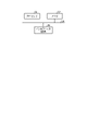
- FIG. 1 is a diagram showing a configuration example of a numerical control device 10, a relocation detection device 20, and a display device 30 according to the present embodiment.
- the numerical control device 10 is connected to the relocation detection device 20, the display device 30, and the machine tool 40.
- the numerical control device 10 is a device used in a machine tool 40 having 5 or more axes.
- the relocation detection device 20 is a device capable of detecting the relocation of the connected numerical control device 10.
- the numerical control device 10 includes a control unit 11, a power supply unit 12, storage devices 13 and 14, and an external I / F (InterFace) 15.
- the control unit 11 includes a contour control unit 111, a storage device I / F power supply circuit 112, and storage devices I / F 113 and 114.
- the numerical control device 10 constitutes hardware 16 for contour control of 5 axes or more capable of controlling contours of 5 axes or more with respect to the machine tool 40 by the storage device I / F 113 and the storage device 13.
- the numerical control device 10 constitutes hardware 17 for contour control of 4 axes or less capable of controlling the contour of 4 axes or less with respect to the machine tool 40 by the storage device I / F 114 and the storage device 14.
- the contour control hardware 16 having five or more axes may be referred to as a first contour control hardware, and the contour control hardware 17 having four or less axes may be referred to as a second contour control hardware. ..
- the power supply unit 12 supplies power to the control unit 11 and the storage devices 13 and 14, and supplies power to the relocation detection device 20 via the external I / F15. ..
- the power supply unit 12 may supply a DC power supply supplied from an external power source (not shown) to each configuration, or receive an AC power supply from an external commercial power source (not shown) and generate a DC power source from the AC power source. May be supplied to each configuration.
- the power supply unit 12 does not supply power to the control unit 11 and the storage devices 13 and 14, but supplies power to the relocation detection device 20 via the external I / F15. do not do.
- the storage device 13 is a first storage device that stores a program used when the numerical control device 10 executes a control process of a contour control function having five or more axes with respect to the machine tool 40.
- the program used when executing the control process of the contour control function having five or more axes is the first program.
- the storage device 14 is a second storage device that stores a program used when the numerical control device 10 executes a control process of a contour control function having four or less axes with respect to the machine tool 40.
- the program used when executing the control process of the contour control function having four or less axes is the second program.
- the external I / F 15 is an interface capable of connecting the numerical control device 10 and the relocation detection device 20.
- the control unit 11 executes the control process of the numerical control device 10.
- the storage device I / F power supply circuit 112 receives power from the power supply unit 12
- the storage device I / F power supply circuit 112 generates a control power supply to the storage devices I / F 113, 114 based on the control of the contour control unit 111.
- supply power The storage device I / F power supply circuit 112 supplies power to the storage devices I / F 113 and 114 based on the control of the contour control unit 111 when the transfer of the numerical control device 10 is not detected by the relocation detection device 20.
- the relocation of the numerical control device 10 is detected by the relocation detection device 20, power is supplied only to the storage device I / F 114.
- the storage device I / F 113 is an interface for connecting the control unit 11 and the storage device 13 and for the control unit 11 and the storage device 13 to communicate with each other.
- the storage device I / F 113 is a first storage device interface capable of reading and writing a program stored in the storage device 13 under the control of the contour control unit 111.
- the storage device I / F 114 is an interface for connecting the control unit 11 and the storage device 14 and for the control unit 11 and the storage device 14 to communicate with each other.
- the storage device I / F 114 is a second storage device interface capable of reading and writing a program stored in the storage device 14 under the control of the contour control unit 111.
- the contour control unit 111 controls the power supply from the storage device I / F power supply circuit 112 to the storage device I / F 113 based on the log stored in the storage device 26 included in the relocation detection device 20 to be described later. Specifically, when the contour control unit 111 has a log indicating that the numerical control device 10 has been relocated to the storage device 26 included in the relocation detection device 20, the numerical control device 10 in the relocation detection device 20. It can be determined that the relocation of the device has been detected. When the relocation detection device 20 detects the relocation of the numerical control device 10, the contour control unit 111 cuts off the power supply from the storage device I / F power supply circuit 112 to the storage device I / F 113 and sends the power supply to the storage device 13. Electrically shut off reading and writing. In this way, the contour control unit 111 controls the contour control hardware 16 having five or more axes so as not to function when the relocation detection device 20 detects the relocation of the numerical control device 10.
- the relocation detection device 20 includes a power supply control circuit 21, an electronic switch 22, a sensor 23, an AD (Analog to Digital) converter 24, a control unit 25, and a storage device 26. Be prepared.
- the relocation detection device 20 is connected to the numerical control device 10 via the external I / F 15 of the numerical control device 10.
- the numerical control device 10 is mounted on the relocation detection device 20 of another unit, that is, the relocation detection device 20 of another unit is mounted on the numerical control device 10. There may be.
- the sensor 23 is a sensor for detecting the relocation of the numerical control device 10.
- the sensor 23 may be one sensor or a plurality of sensors.
- the sensor 23 mounts, for example, one or more of an acceleration sensor, an angular velocity sensor, and a vibration sensor.
- the sensor 23 detects changes in inertia that occur when the numerical control device 10 is relocated, such as tilt, movement, vibration, and impact.
- the AD converter 24 is a converter that converts the detected value of analog data detected by the sensor 23 into AD conversion, that is, the detected value of digital data.
- the control unit 25 compares the detected value of the digital data converted by the AD converter 24 with the threshold value for determining the relocation of the numerical control device 10 stored in advance in the storage device 26. When the detected value exceeds the threshold value, the control unit 25 determines that the numerical control device 10 has been relocated, and stores the relocation log indicating that the numerical control device 10 has been relocated in the storage device 26. The control unit 25 notifies the numerical control device 10 of the presence / absence of a log of relocation in the storage device 26 based on the request from the numerical control device 10.
- the storage device 26 stores a threshold value for determining the relocation of the numerical control device 10.
- the relocation detection device 20 takes into consideration the detection error of the sensor 23, the error of the AD converter 24, the variation of the parts used in the relocation detection device 20, the measured value at the time of relocation of the numerical control device 10, and the like.
- the manufacturer or the like calculates in advance and stores it in the storage device 26.
- the storage device 26 stores a log indicating the operating state of the relocation detection device 20.
- the log indicating the operating state includes the above-mentioned log with relocation, which is the result of determination by the control unit 25 of the relocation detection device 20 that the numerical control device 10 has been relocated.
- the power supply control circuit 21 includes a secondary battery 211 for backup.
- the power supply control circuit 21 receives power from the power supply unit 12 of the numerical control device 10 via the external I / F 15 when the power of the numerical control device 10 is turned on.
- the power supply control circuit 21 controls the electronic switch 22 by the power supply switching signal, and controls the sensor 23, the AD converter 24, the control unit 25, and the storage.
- the power supply unit 12 of the numerical control device 10 is selected as the power supply source of the device 26. Further, when the power supply control circuit 21 is supplied with power from the power supply unit 12 of the numerical control device 10, the power supply is supplied from the power supply unit 12 of the numerical control device 10, and the secondary battery 211 for backup is used. To charge. It is assumed that the power supply control circuit 21 measures the voltage of the power supply path supplied from the power supply unit 12 of the numerical control device 10 via the external I / F 15 when the power of the numerical control device 10 is turned on. ..
- the numerical control device 10 stops supplying power to the relocation detection device 20 via the external I / F 15.
- the power supply control circuit 21 detects that the power supply of the numerical control device 10 is switched from on to off due to a voltage drop in the power supply path.
- the power supply control circuit 21 outputs a power supply switching signal to the electronic switch 22 when the voltage of the power supply path becomes equal to or lower than the above-mentioned threshold voltage obtained by adding a margin to the lower limit voltage at which the control unit 25 can operate.
- the electronic switch 22 is controlled to switch the power supply source of the sensor 23, the AD converter 24, the control unit 25, and the storage device 26.
- the power supply control circuit 21 selects the secondary battery 211 of the power supply control circuit 21 as the power supply source of the sensor 23, the AD converter 24, the control unit 25, and the storage device 26. That is, the power supply control circuit 21 supplies power to the sensor 23, the AD converter 24, the control unit 25, and the storage device 26 when the power of the numerical control device 10 is turned off. As a result, the relocation detection device 20 can continue to operate even when the power of the numerical control device 10 is turned off, that is, continuously monitor the numerical control device 10 and detect the relocation of the numerical control device 10.
- the power supply control circuit 21 may include a capacitor (not shown) instead of the secondary battery 211 as a backup configuration.
- the display device 30 includes a display unit 31.
- the display unit 31 displays the status of the numerical control device 10 and the machine tool 40 to the operator under the control of the control unit 11 of the numerical control device 10.
- the display unit 31 for example, when the function of the numerical control device 10 is restricted due to the relocation of the numerical control device 10, the function of the numerical control device 10 is restricted by the control of the control unit 11 of the numerical control device 10. Displays an alarm display or the like indicating that the device is in the current state.
- the machine tool 40 is a device having 5 or more axes and capable of machining a machine tool using a plurality of tools.
- the machine tool 40 is, for example, a device for performing cutting, but is not limited thereto.
- the machine tool 40 may be a device for performing laser machining, a device for performing electric discharge machining, or the like.
- the machine tool 40 may be mounted on the numerical control device 10, that is, the numerical control device 10 may be mounted on the machine tool 40.
- the relocation of the numerical control device 10 is the same as the relocation of the machine tool 40 on which the numerical control device 10 is mounted.
- the contour control unit 111 of the numerical control device 10 communicates with the control unit 25 of the relocation detection device 20.
- the contour control unit 111 confirms whether or not the log of the relocation is stored in the storage device 26 of the relocation detection device 20 via the control unit 25, so that the numerical value can be measured while the power of the numerical control device 10 is turned off. It is determined whether or not the control device 10 has been relocated.
- the contour control unit 111 when the log of the relocation is not stored in the storage device 26 of the relocation detection device 20, the numerical control device 10 is not relocated while the power of the numerical control device 10 is turned off. Judge.
- the contour control unit 111 determines that the numerical control device 10 has been relocated while the power of the numerical control device 10 is turned off.
- the method by which the contour control unit 111 confirms whether or not the log of the relocation is stored in the storage device 26 of the relocation detection device 20 is not particularly limited.
- the contour control unit 111 requests the control unit 25 of the relocation detection device 20 to provide information on the presence or absence of a log of relocation in the storage device 26, and the control unit 25 of the relocation detection device 20 requests the contour control unit 111. Is notified of the presence / absence of the relocation log in the storage device 26.
- the contour control unit 111 requests and acquires the log stored in the storage device 26 from the control unit 25 of the relocation detection device 20, and whether or not the acquired log includes the log with relocation. You may check if.
- the contour control unit 111 determines that the numerical control device 10 has not been relocated, the contour control unit 111 reads the program stored in the storage device 13 via the storage device I / F 113, and reads the program stored in the storage device 13 via the storage device I / F 114. Read the program stored in the storage device 14.
- the numerical control device 10 is a program used when executing the control processing of the contour control function of 5 axes or more stored in the storage device 13, and the contour control function of 4 axes or less stored in the storage device 14.
- the machine tool 40 is controlled by executing a program used when executing the control process.
- the contour control unit 111 determines that the numerical control device 10 has been relocated, the contour control unit 111 controls the storage device I / F power supply circuit 112 to control the power supply from the storage device I / F power supply circuit 112 to the storage device I / F 113. To shut off.
- the contour control unit 111 reads the log with relocation from the storage device 26 of the relocation detection device 20, it is an abnormal case. As a result, the contour control unit 111 cannot read the program stored in the storage device 13 via the storage device I / F 113, and invalidates the contour control hardware 16 having five or more axes.
- the contour control unit 111 enables the contour control hardware 17 having four or less axes by reading the program stored in the storage device 14 via the storage device I / F 114. That is, the numerical control device 10 executes a program used when executing the control process of the contour control function of four axes or less stored in the storage device 14, and controls the machine tool 40. As described above, when it is determined that the numerical control device 10 has been relocated, the contour control unit 111 limits the function of disabling the contour control hardware 16 having five or more axes.
- the storage device I / F power supply circuit 112 receives power from the power supply unit 12, and is controlled by the contour control unit 111 for the storage device I / F 113.
- the control power supply for the storage device I / F114 is generated and supplied to the storage device I / F 113, and the control power supply for the storage device I / F 114 is generated and supplied to the storage device I / F 114.
- the storage device I / F 113 can read the program stored in the storage device 13 while receiving the control power supply for the storage device I / F 113 from the storage device I / F power supply circuit 112.
- the storage device I / F 114 can read the program stored in the storage device 14 while receiving the control power supply for the storage device I / F 114 from the storage device I / F power supply circuit 112.
- the storage device I / F power supply circuit 112 does not generate a control power supply for the storage device I / F 113 under the control of the contour control unit 111, and is a storage device.
- the control power supply for the storage device I / F 113 is not supplied to the I / F 113.
- the storage device I / F power supply circuit 112 generates a control power supply for the storage device I / F 114 and supplies it to the storage device I / F 114 even when the numerical control device 10 is relocated.
- the storage device I / F power supply circuit 112 stops generating only the control power supply for the storage device I / F 113, and only supplies the control power supply to the storage device I / F 113. By shutting off, the function of the contour control hardware 16 having five or more axes is stopped, that is, disabled.
- the control unit 11 is composed of one electric component, for example, a system LSI (Large Scale Integration)
- the storage device I / F power supply circuit 112 and the storage device I / F 113 are included in the same system LSI. Is done.
- the power supply line for the control power supply from the storage device I / F power supply circuit 112 to the storage device I / F 113 is a closed circuit in the system LSI. Therefore, the person who has relocated the numerical control device 10 connects the power supply to the storage device I / F 113 from the control unit 11, that is, the outside of the system LSI, supplies the control power supply, and turns on the storage device I / F 113. It is not possible.
- the power supply line from the storage device I / F power supply circuit 112 to the storage device I / F 113 is in the system LSI. It is grounded to 0V (GND). Therefore, the person who has relocated the numerical control device 10 cannot pull out the power line of the storage device I / F 113 from the system LSI by modifying it, connect an external power supply, and turn on the storage device I / F 113.
- the logic circuit of the system LSI is already set before mounting on the board, and cannot be rewritten after mounting on the board. Therefore, the person who relocated the numerical control device 10 cannot turn on the storage device I / F 113 by rewriting the logic circuit.
- the contour control unit 111 of the numerical control device 10 determines whether or not the relocation detection device 20 is connected to the numerical control device 10.
- the contour control unit 111 controls the storage device I / F power supply circuit 112 as in the case of detecting the relocation, and the storage device I / F power supply.
- the control power supply from the circuit 112 to the storage device I / F 113 is cut off. If the relocation detection device 20 is not connected to the numerical control device 10, it is an abnormal case. That is, the case of a communication error is an abnormal case.
- the contour control unit 111 cannot read the program stored in the storage device 13 via the storage device I / F 113, and invalidates the contour control hardware 16 having five or more axes.
- the contour control unit 111 enables the contour control hardware 17 having four or less axes by reading the program stored in the storage device 14 via the storage device I / F 114.
- the contour control unit 111 limits the function of disabling the contour control hardware 16 having five or more axes even when it is determined that the relocation detection device 20 is not connected to the numerical control device 10.
- the contour control unit 111 communicates with the control unit 25 of the relocation detection device 20.
- the contour control unit 111 disconnects the communication signal line between the numerical control device 10 and the relocation detection device 20 to cause the relocation detection device 20. Communication with the control unit 25 of the above becomes impossible, and a communication error occurs.
- the contour control unit 111 can determine that the relocation detection device 20 has been removed from the external I / F 15 of the numerical control device 10 due to the communication error interrupt generated at the time of the communication error.
- the contour control unit 111 determines that the relocation detection device 20 has been removed from the external I / F 15 of the numerical control device 10 while the power of the numerical control device 10 is on, it is the same as when the relocation of the numerical control device 10 is detected.
- the storage device I / F power supply circuit 112 is controlled to cut off the control power supply from the storage device I / F power supply circuit 112 to the storage device I / F 113.
- the contour control unit 111 cannot read the program stored in the storage device 13 via the storage device I / F 113, and invalidates the contour control hardware 16 having five or more axes.
- the contour control unit 111 enables the contour control hardware 17 having four or less axes by reading the program stored in the storage device 14 via the storage device I / F 114. As described above, when the contour control unit 111 determines that the relocation detection device 20 has been removed from the external I / F 15 of the numerical control device 10 while the power of the numerical control device 10 is on, the contour control hardware for five or more axes is used. The function to invalidate 16 is restricted.
- the sensor 23, the AD converter 24, the control unit 25, the storage device 26, and the power supply control circuit 21 are supplied with power from the power supply unit 12 of the numerical control device 10 via the external I / F15.
- the power control circuit 21 of the relocation detection device 20 includes a secondary battery 211 for backup, and power is supplied from the power supply unit 12 of the numerical control device 10 via the external I / F 15 while the power of the numerical control device 10 is on. To. While the power of the numerical control device 10 is turned on, the secondary battery 211 is charged by the power control circuit 21. When the power of the numerical control device 10 is turned off, the power supply control circuit 21 detects a voltage drop in the supply path of the power supply supplied from the power supply unit 12 of the numerical control device 10, and the detected voltage is the lower limit of the operation of the control unit 25. When the voltage reaches the threshold value in which the margin is added to the voltage of the above, the power supply switching signal is output to the electronic switch 22 of the relocation detection device 20.
- the power supply control circuit 21 switches the power supply path to the sensor 23, the AD converter 24, the control unit 25, and the storage device 26 from the power supply unit 12 of the numerical control device 10 to the secondary battery 211, whereby the relocation detection device 20 Can continue to operate even when the power of the numerical control device 10 is turned off.
- the control unit 25 of the relocation detection device 20 transfers the detection value of the digital data acquired from the AD converter 24 to the storage device 26 regardless of the power on / off state of the numerical control device 10. It is compared with the threshold value stored in advance, it is determined that the numerical control device 10 has been relocated, and the log of the relocation is stored in the storage device 26. Further, when the relocation detection device 20 is removed from the numerical control device 10 while the power of the numerical control device 10 is turned off and the relocation detection device 20 is connected to the original numerical control device 10 after the numerical control device 10 is relocated, the relocation detection device 10 is detected.
- the control unit 25 of the device 20 changes the inertia when the relocation detection device 20 is removed from the numerical control device 10, for example, tilt, movement, vibration, and impact. Etc. can be detected. In this case as well, the control unit 25 of the relocation detection device 20 determines that the numerical control device 10 has been relocated, and stores the log of the relocation in the storage device 26.
- the detection value of the digital data converted from the detection value of the analog data by the AD converter 24 exceeds the threshold value stored in advance in the storage device 26. It becomes a constant value. If the sensor 23 of the relocation detection device 20 fails due to a disconnection, a short circuit, or the like, it is an abnormal case. In this case, the control unit 25 of the relocation detection device 20 determines that the relocation detection device 20 is abnormal. When the control unit 25 of the relocation detection device 20 detects an abnormality inside the relocation detection device 20, the storage device 26 stores a log of the device abnormality indicating the abnormality of the relocation detection device 20. The control unit 25 of the relocation detection device 20 notifies the numerical control device 10 of the presence or absence of a log of device abnormality based on the request from the numerical control device 10.
- the contour control unit 111 of the numerical control device 10 determines that the relocation detection device 20 is in a state where the relocation detection device 20 cannot normally detect the relocation, and the relocation detection device 20 determines. The same control as when the relocation of the numerical control device 10 is detected is performed. That is, the contour control unit 111 controls the storage device I / F power supply circuit 112 to cut off the control power supply from the storage device I / F power supply circuit 112 to the storage device I / F 113. As a result, the contour control unit 111 cannot read the program stored in the storage device 13 via the storage device I / F 113, and invalidates the contour control hardware 16 having five or more axes.
- the contour control unit 111 enables the contour control hardware 17 having four or less axes by reading the program stored in the storage device 14 via the storage device I / F 114. As described above, when the contour control unit 111 determines that the relocation detection device 20 cannot normally detect the relocation, the contour control unit 111 limits the function of disabling the contour control hardware 16 having five or more axes.
- the control unit 25 causes the control unit 25 to operate. It is determined that the relocation detection device 20 is abnormal, and the log of the device abnormality is stored in the storage device 26.
- the contour control unit 111 of the numerical control device 10 controls the display unit 31 of the display device 30 to display an alarm display such as "5-axis control invalid" on the display unit 31.
- an alarm display such as "5-axis control invalid"
- the operator can visually grasp that the numerical control device 10 is in the function-restricted state at the time of operation.
- the operator recognizes that the contour control hardware 16 having five or more axes is disabled in the numerical control device 10 and the functions are restricted. can do.
- the contour control hardware 16 of 5 axes or more is disabled in the numerical control device 10, and the 5 axes are disabled. Since the above contour control program cannot be read or written, the contour control program having five or more axes does not operate. Even when the numerical control device 10 is in the function limited state, the numerical control device 10 can operate the contour control program having four or less axes. The operator can perform contour control of 4 axes or less by using the numerical control device 10.
- FIG. 2 is a flowchart showing the operation of the numerical control device 10 according to the present embodiment.
- the operator turns on the power of the numerical control device 10 and the display device 30 (step S1), and activates each device.
- the power supply control circuit 21 of the relocation detection device 20 detects the voltage of the power supply unit 12 when the power of the numerical control device 10 is turned on. When the voltage of the power supply unit 12 reaches the rated voltage, the power supply control circuit 21 outputs a power supply switching signal to the electronic switch 22 of the relocation detection device 20, and outputs a power supply switching signal to the sensor 23, the AD converter 24, the control unit 25, and the storage device 26.
- the power supply path to is switched from the secondary battery 211 to the power supply unit 12 of the numerical control device 10.
- the numerical control device 10 starts the loop processing of steps S3 and S4 described below after the power of the numerical control device 10 and the display device 30 is turned on and the system of each device is started (step S2).
- the contour control unit 111 of the numerical control device 10 confirms whether or not communication is possible between the relocation detection device 20 and the numerical control device 10 (step S3). Specifically, the contour control unit 111 confirms whether or not communication is possible between the control unit 25 of the relocation detection device 20 and the contour control unit 111 of the numerical control device 10. When the relocation detection device 20 is connected to the numerical control device 10 and communication is possible (step S3: Yes), the contour control unit 111 proceeds to step S4. When the contour control unit 111 cannot communicate due to the removal or failure of the relocation detection device 20 (step S3: No), the contour control unit 111 determines that the relocation detection device 20 is abnormal and proceeds to step S6.
- the contour control unit 111 is stored in the storage device 26 by communication with the control unit 25 of the relocation detection device 20. To monitor. Specifically, the control unit 25 transmits to the contour control unit 111 information on the presence / absence of a log of relocation and a log of device abnormality in the storage device 26. The contour control unit 111 confirms whether or not the storage device 26 of the relocation detection device 20 has a log of relocation or a log of device abnormality based on the information acquired from the control unit 25 (step S4).
- step S4: Yes When the contour control unit 111 has a log of relocation in the storage device 26 of the relocation detection device 20 (step S4: Yes), the contour control unit 111 determines that the numerical control device 10 has been relocated, and proceeds to step S6. If the storage device 26 of the relocation detection device 20 has a device abnormality log (step S4: Yes), the contour control unit 111 determines that the relocation detection device 20 has an abnormality and proceeds to step S6. The contour control unit 111 proceeds to step S6 even when the storage device 26 of the relocation detection device 20 has both a log of relocation and a log of device abnormality (step S4: Yes). The contour control unit 111 returns to step S3 by loop processing when neither the relocation existence log nor the device abnormality log is present in the storage device 26 of the relocation detection device 20 (step S4: No).
- the numerical control device 10 After the system of the numerical control device 10 and the display device 30 is started, the numerical control device 10 returns to step S3 and executes the next loop processing of step S3 and step S4 when one loop processing of step S3 and step S4 is completed. (Step S5).
- step S6 the contour control unit 111 limits the function of enabling the contour control hardware 17 of 4 axes or less while disabling the contour control hardware 16 of 5 axes or more.
- Step S6 the contour control unit 111 controls the storage device I / F power supply circuit 112 to cut off the control power supply from the storage device I / F power supply circuit 112 to the storage device I / F 113. That is, the contour control unit 111 has a log of relocation indicating that the numerical control device 10 has been relocated to the storage device 26 included in the relocation detection device 20, and a log of device abnormality indicating an abnormality of the relocation detection device 20.
- the power supply from the storage device I / F power supply circuit 112 to the storage device I / F 113 is cut off.
- the contour control unit 111 cannot read the program stored in the storage device 13 via the storage device I / F 113, and invalidates the contour control hardware 16 having five or more axes.
- the contour control unit 111 reads the program stored in the storage device 14 via the storage device I / F 114 by continuing the supply of power from the storage device I / F power supply circuit 112 to the storage device I / F 114.
- This enables contour control hardware 17 with 4 or less axes.
- the numerical control device 10 enables the contour control hardware 17 having four or less axes even when the function is restricted due to erroneous detection, so that the influence on the customer can be reduced.
- the contour control unit 111 controls the display unit 31 of the display device 30 to display a warning display indicating that the numerical control device 10 is in the function-restricted state, that is, an alarm display on the display unit 31 (step S7).
- the display unit 31 displays an alarm display such as "5-axis control invalid" under the control of the contour control unit 111, so that the operator visually grasps that the numerical control device 10 is in the function restricted state at the time of operation. It can be so.
- the operator invalidates the state of step S6, that is, the contour control hardware 16 having five or more axes in the numerical control device 10, and the function is restricted. You can recognize that.
- the relocation detection device 20 accepts a release operation for releasing the functional restriction of the numerical control device 10 by an engineer who provides services such as repair and maintenance of each device such as the numerical control device 10 and the relocation detection device 20 (step S8). ).
- the engineer clears the relocation existence log stored in the storage device 26 of the relocation detection device 20 with the relocation detection device 20 connected to the numerical control device 10.
- the functional restriction of the numerical control device 10 can be released.
- the method of clearing the relocation log stored in the storage device 26 is not disclosed to the user. As a result, the user cannot arbitrarily clear the relocation log stored in the storage device 26.
- the storage device 26 of the relocation detection device 20 has a log of device abnormality, it means that the relocation detection device 20 is abnormal, and the engineer repairs or replaces the relocation detection device 20.
- the engineer can release the functional restriction of the numerical control device 10 by restoring the relocation detection device 20 to a state in which it operates normally.
- the contour control unit 111 of the numerical control device 10 starts communication between the relocation detection device 20 and the numerical control device 10 (step S9).
- communication is normally performed between the relocation detection device 20 and the numerical control device 10.
- the contour control unit 111 controls the storage device I / F power supply circuit 112 to supply a control power supply from the storage device I / F power supply circuit 112 to the storage device I / F 113, and the storage device I / F 113 is the storage device 13. Return the program stored in to the readable state. As a result, the contour control unit 111 cancels the functional restriction of the numerical control device 10 by enabling the contour control hardware 16 having five or more axes (step S10).
- the contour control unit 111 controls the display unit 31 of the display device 30 to cancel the alarm display of the display unit 31 indicating that the numerical control device 10 is in the function limited state (step S11).
- the operator turns off the power of the numerical control device 10 and the display device 30 (step S12).
- the power supply control circuit 21 of the relocation detection device 20 detects a voltage drop in the power supply unit 12 of the numerical control device 10, and when the control unit 25 reaches a threshold value in which a margin is added to the lower limit voltage at which the control unit 25 can operate, the relocation detection device 20 A power supply switching signal is output to the electronic switch 22 of.
- the relocation detection device 20 switches the power supply path to the sensor 23, the AD converter 24, the control unit 25, and the storage device 26 from the power supply unit 12 of the numerical control device 10 to the secondary battery 211, whereby the numerical control device 10 And even after the power of the display device 30 is turned off, the operation, that is, the monitoring of the relocation of the numerical control device 10 can be continued.
- the relocation detection device 20 also includes the sensor 23, the AD converter 24, the control unit 25, and the storage device.
- the power supply path to the 26 can be switched from the power supply unit 12 of the numerical control device 10 to the secondary battery 211, and the monitoring of the relocation of the numerical control device 10 can be continued.
- FIG. 3 is a diagram showing an example of the hardware configuration of the numerical control device 10 according to the present embodiment.
- the numerical control device 10 includes a computer including a processor 91, a memory 92, and an interface circuit 93.
- the processor 91, the memory 92, and the interface circuit 93 can send and receive information to and from each other by, for example, the bus 94.
- the storage devices 13 and 14 are realized by the memory 92.
- the external I / F 15 is realized by the interface circuit 93.
- the processor 91 executes functions such as the control unit 11 and the power supply unit 12 by reading and executing the program stored in the memory 92.
- the power supply unit 12 may be realized by a power conversion circuit or the like capable of generating desired power.
- the processor 91 is, for example, an example of a processing circuit, and includes one or more of a CPU (Central Processing Unit), a DSP (Digital Signal Processor), and a system LSI.
- the memory 92 is RAM (Random Access Memory), ROM (Read Only Memory), flash memory, EPROM (Erasable Programmable Read Only Memory), EEPROM (registered trademark) (Electrically Erasable Programmable Read Only Memory), HDD (Hard Disk Drive). , And one or more of SSD (Solid State Drive). Further, the memory 92 includes a recording medium in which a computer-readable program is recorded. Such recording media include one or more of non-volatile or volatile semiconductor memories, magnetic disks, flexible memories, optical discs, compact disks, and DVDs (Digital Versatile Discs).
- the numerical control device 10 may include integrated circuits such as an ASIC (Application Specific Integrated Circuit) and an FPGA (Field Programmable Gate Array).
- the relocation detection device 20 is also realized by the hardware configuration as shown in FIG. 3, like the numerical control device 10.
- the numerical control device 10 when the relocation detection device 20 detects the relocation of the numerical control device 10, the numerical control device 10 has the storage device I / F from the storage device I / F power supply circuit 112. The generation of the control power supply to the F113 is stopped, and the reading / writing to / from the storage device 13 storing the program used when executing the control processing of the contour control function of 5 axes or more is electrically cut off. It was decided to disable the contour control hardware 16 above the axis. As a result, the numerical control device 10 can avoid disabling the relocation prevention function due to hardware modification.
- the numerical control device 10 controls the contour control function of 4 axes or less in a storage device 14 different from the storage device 13 for storing the program used when executing the control process of the contour control function of 5 axes or more. Stores the program used to execute the process. Therefore, the numerical control device 10 can enable the contour control hardware 17 having four or less axes having the storage device 14 while disabling the contour control hardware 16 having five or more axes having the storage device 13, which is erroneous. The impact on the customer at the time of detection can be minimized.
- the numerical control device 10 has a storage device 13 for storing the first program and a storage device 14 for storing the second program in separate configurations, but both are in the same storage device.
- the program may be stored and the reading of each program may be enabled / disabled by software.
- the control unit 11 of the numerical control device 10 communicates with the relocation detection device 20, and when an abnormal signal is acquired from the relocation detection device 20, the second program is read and executed, and in other cases, the first Load and execute the program of. Also in this case, the same effect as that of the present embodiment can be obtained. Further, by detecting the relocation of the numerical control device 10 by the relocation detection device 20 which is a unit different from the numerical control device 10, the numerical control device 10 has the same configuration as the conventional one, and the model can be unified at low cost. By connecting the numerical control device 10 to the relocation detection device 20 of another unit, the function of the relocation detection device 20 can be easily added.
- the configuration shown in the above embodiments is an example, and can be combined with another known technique, can be combined with each other, and does not deviate from the gist. It is also possible to omit or change a part of the configuration.
Landscapes
- Engineering & Computer Science (AREA)
- Human Computer Interaction (AREA)
- Manufacturing & Machinery (AREA)
- Physics & Mathematics (AREA)
- General Physics & Mathematics (AREA)
- Automation & Control Theory (AREA)
- Numerical Control (AREA)
Abstract
Description
図1は、本実施の形態に係る数値制御装置10、移設検知装置20、および表示装置30の構成例を示す図である。数値制御装置10は、移設検知装置20、表示装置30、および工作機械40に接続される。数値制御装置10は、軸数が5軸以上の工作機械40で使用される装置である。移設検知装置20は、接続される数値制御装置10の移設を検知可能な装置である。
Claims (9)
- 第1のプログラム、および第2のプログラムを記憶する記憶装置と、
移設検知装置と通信を行い、前記移設検知装置から異常な信号を取得した場合、前記第2のプログラムを読み込み実行し、その他の場合、前記第1のプログラムを読み込み実行する制御部と、
前記記憶装置、および前記制御部に電源を供給する電源部と、
を備えることを特徴とする数値制御装置。 - 軸数が5軸以上の工作機械で使用される数値制御装置であって、
前記工作機械に対して5軸以上の輪郭制御が可能な第1の輪郭制御用ハードウェアと、
前記工作機械に対して4軸以下の輪郭制御が可能な第2の輪郭制御用ハードウェアと、
前記数値制御装置の移設を検知可能な移設検知装置において前記数値制御装置の移設が検知された場合、前記第1の輪郭制御用ハードウェアを機能しないように制御する輪郭制御部と、
を備えることを特徴とする数値制御装置。 - 前記第1の輪郭制御用ハードウェアは、前記数値制御装置が5軸以上の輪郭制御機能の制御処理を実行する際に使用するプログラムを格納する第1の記憶装置、を備え、
前記輪郭制御部は、前記移設検知装置において前記数値制御装置の移設が検知された場合、前記第1の記憶装置への読み書きを電気的に遮断する、
ことを特徴とする請求項2に記載の数値制御装置。 - 前記第1の輪郭制御用ハードウェアは、前記数値制御装置が5軸以上の輪郭制御機能の制御処理を実行する際に使用するプログラムを読み書き可能な第1の記憶装置インタフェース、を備え、
前記輪郭制御部は、前記移設検知装置において前記数値制御装置の移設が検知された場合、前記数値制御装置の移設が検知されていない状態のときに前記第1の記憶装置インタフェースに電源供給を行う記憶装置インタフェース電源回路から前記第1の記憶装置インタフェースへの電源供給を遮断し、
前記第1の記憶装置インタフェースおよび前記記憶装置インタフェース電源回路は同一の電気部品に含まれる、
ことを特徴とする請求項2または3に記載の数値制御装置。 - 前記輪郭制御部は、前記移設検知装置が備える記憶装置に格納されているログに基づいて、前記記憶装置インタフェース電源回路から前記第1の記憶装置インタフェースへの電源供給を制御する、
ことを特徴とする請求項4に記載の数値制御装置。 - 前記輪郭制御部は、前記移設検知装置が備える前記記憶装置に、前記数値制御装置が移設されたことを示す移設有のログ、および前記移設検知装置の異常を示す装置異常のログのうち少なくとも1つが格納されている場合、前記記憶装置インタフェース電源回路から前記第1の記憶装置インタフェースへの電源供給を遮断する、
ことを特徴とする請求項5に記載の数値制御装置。 - 接続される数値制御装置の移設を検知可能な移設検知装置であって、
前記数値制御装置の移設を検知するためのセンサと、
前記センサで検出された検出値をアナログデータからデジタルデータに変換する変換器と、
前記移設検知装置の動作状態を示すログを格納する記憶装置と、
前記変換器でアナログデータからデジタルデータに変換された検出値が前記数値制御装置の移設を判定するための閾値を超える場合、前記数値制御装置が移設されたことを示す移設有のログを前記記憶装置に格納させる制御部と、
を備え、
前記制御部は、前記数値制御装置からの要求に基づいて、前記記憶装置における前記移設有のログの有無を前記数値制御装置に通知する、
ことを特徴とする移設検知装置。 - 前記制御部は、前記移設検知装置の内部で異常を検知した場合は前記移設検知装置の異常を示す装置異常のログを前記記憶装置に格納させ、前記数値制御装置からの要求に基づいて、前記装置異常のログの有無を前記数値制御装置に通知する、
ことを特徴とする請求項7に記載の移設検知装置。 - 二次バッテリまたはコンデンサを有し、前記数値制御装置の電源オフ時に、前記センサ、前記変換器、前記制御部、および前記記憶装置に電源供給可能な電源制御回路、
を備え、
前記数値制御装置の電源オフ時においても前記数値制御装置の移設を検知する機能を有する、
ことを特徴とする請求項7または8に記載の移設検知装置。
Priority Applications (4)
| Application Number | Priority Date | Filing Date | Title |
|---|---|---|---|
| CN202080102143.7A CN115917450B (zh) | 2020-11-26 | 2020-11-26 | 数控装置 |
| JP2021519901A JP6899988B1 (ja) | 2020-11-26 | 2020-11-26 | 数値制御装置 |
| PCT/JP2020/044017 WO2022113237A1 (ja) | 2020-11-26 | 2020-11-26 | 数値制御装置および移設検知装置 |
| DE112020007086.7T DE112020007086B4 (de) | 2020-11-26 | 2020-11-26 | Numerische Steuerung und Vorrichtung zur Erfassung von Ortsveränderungen |
Applications Claiming Priority (1)
| Application Number | Priority Date | Filing Date | Title |
|---|---|---|---|
| PCT/JP2020/044017 WO2022113237A1 (ja) | 2020-11-26 | 2020-11-26 | 数値制御装置および移設検知装置 |
Publications (1)
| Publication Number | Publication Date |
|---|---|
| WO2022113237A1 true WO2022113237A1 (ja) | 2022-06-02 |
Family
ID=76650095
Family Applications (1)
| Application Number | Title | Priority Date | Filing Date |
|---|---|---|---|
| PCT/JP2020/044017 Ceased WO2022113237A1 (ja) | 2020-11-26 | 2020-11-26 | 数値制御装置および移設検知装置 |
Country Status (4)
| Country | Link |
|---|---|
| JP (1) | JP6899988B1 (ja) |
| CN (1) | CN115917450B (ja) |
| DE (1) | DE112020007086B4 (ja) |
| WO (1) | WO2022113237A1 (ja) |
Citations (7)
| Publication number | Priority date | Publication date | Assignee | Title |
|---|---|---|---|---|
| JP2006215951A (ja) * | 2005-02-07 | 2006-08-17 | Tokyo Seimitsu Co Ltd | 機器及びその起動制御方法 |
| JP2009146376A (ja) * | 2007-11-22 | 2009-07-02 | Fanuc Ltd | 移設検出機能を備えた数値制御装置 |
| JP2009187234A (ja) * | 2008-02-06 | 2009-08-20 | Fanuc Ltd | 移設防止機能を有する数値制御装置 |
| JP2009205545A (ja) * | 2008-02-28 | 2009-09-10 | Star Micronics Co Ltd | 工作機械、不正移設通知装置および機械動作制限方法 |
| JP2011145804A (ja) * | 2010-01-13 | 2011-07-28 | Murata Machinery Ltd | 移設検知機能付き産業機械 |
| JP2013134540A (ja) * | 2011-12-26 | 2013-07-08 | Mitsubishi Heavy Ind Ltd | 移設検知システム |
| JP2017117223A (ja) * | 2015-12-24 | 2017-06-29 | ブラザー工業株式会社 | 移設制限装置、工作機械、移設制限方法及びコンピュータプログラム |
Family Cites Families (9)
| Publication number | Priority date | Publication date | Assignee | Title |
|---|---|---|---|---|
| FR2743015B1 (fr) * | 1995-12-29 | 1998-03-27 | Helis Sa | Machine a portique mobile avec des montants mobiles l'un par rapport a l'autre |
| JP4261708B2 (ja) * | 1999-12-01 | 2009-04-30 | 東芝機械株式会社 | Nc加工装置 |
| JP2003058285A (ja) * | 2001-08-10 | 2003-02-28 | Fujitsu Ten Ltd | 制御システム |
| JP2008234278A (ja) * | 2007-03-20 | 2008-10-02 | Brother Ind Ltd | 数値制御装置、制御プログラム、制御プログラム記録媒体及び工作機械 |
| JP6130800B2 (ja) * | 2014-03-06 | 2017-05-17 | 株式会社日立製作所 | 計算機装置 |
| JP2016181055A (ja) * | 2015-03-23 | 2016-10-13 | 株式会社東芝 | 情報処理装置 |
| JP2017073895A (ja) * | 2015-10-07 | 2017-04-13 | ファナック株式会社 | Rfタグを有するモータ駆動装置 |
| JP2018147346A (ja) * | 2017-03-08 | 2018-09-20 | ブラザー工業株式会社 | 工作機械 |
| DE112018000259T5 (de) * | 2018-06-07 | 2020-02-13 | Mitsubishi Electric Corporation | Numerische Steuervorrichtung und Informationsverarbeitungsvorrichtung |
-
2020
- 2020-11-26 CN CN202080102143.7A patent/CN115917450B/zh active Active
- 2020-11-26 DE DE112020007086.7T patent/DE112020007086B4/de active Active
- 2020-11-26 JP JP2021519901A patent/JP6899988B1/ja active Active
- 2020-11-26 WO PCT/JP2020/044017 patent/WO2022113237A1/ja not_active Ceased
Patent Citations (7)
| Publication number | Priority date | Publication date | Assignee | Title |
|---|---|---|---|---|
| JP2006215951A (ja) * | 2005-02-07 | 2006-08-17 | Tokyo Seimitsu Co Ltd | 機器及びその起動制御方法 |
| JP2009146376A (ja) * | 2007-11-22 | 2009-07-02 | Fanuc Ltd | 移設検出機能を備えた数値制御装置 |
| JP2009187234A (ja) * | 2008-02-06 | 2009-08-20 | Fanuc Ltd | 移設防止機能を有する数値制御装置 |
| JP2009205545A (ja) * | 2008-02-28 | 2009-09-10 | Star Micronics Co Ltd | 工作機械、不正移設通知装置および機械動作制限方法 |
| JP2011145804A (ja) * | 2010-01-13 | 2011-07-28 | Murata Machinery Ltd | 移設検知機能付き産業機械 |
| JP2013134540A (ja) * | 2011-12-26 | 2013-07-08 | Mitsubishi Heavy Ind Ltd | 移設検知システム |
| JP2017117223A (ja) * | 2015-12-24 | 2017-06-29 | ブラザー工業株式会社 | 移設制限装置、工作機械、移設制限方法及びコンピュータプログラム |
Also Published As
| Publication number | Publication date |
|---|---|
| JPWO2022113237A1 (ja) | 2022-06-02 |
| CN115917450A (zh) | 2023-04-04 |
| JP6899988B1 (ja) | 2021-07-07 |
| DE112020007086B4 (de) | 2025-06-12 |
| CN115917450B (zh) | 2023-10-31 |
| DE112020007086T5 (de) | 2023-02-16 |
Similar Documents
| Publication | Publication Date | Title |
|---|---|---|
| CN106326061B (zh) | 高速缓存数据处理方法及设备 | |
| WO1997031254A1 (en) | On-vehicle controller failure diagnosing method and apparatus | |
| CN111400136A (zh) | 服务器专用的gpu故障保护装置、方法、设备及介质 | |
| JP2002529853A (ja) | 大容量メモリを備えたサブシステムのハードディスクのために書き込みを保護したディスクキャッシュ装置と方法 | |
| JP6899988B1 (ja) | 数値制御装置 | |
| JP4945471B2 (ja) | 移設防止機能を有する数値制御装置 | |
| CN113901530A (zh) | 一种硬盘防御性预警保护的方法、装置、设备及可读介质 | |
| CN105644369A (zh) | 电机控制器及其复位处理方法和装置 | |
| US8024604B2 (en) | Information processing apparatus and error processing | |
| US7650439B2 (en) | Falling protective device for hard disk of a portable computer | |
| TW201426292A (zh) | 伺服器及其風扇故障時的保護方法 | |
| US8132196B2 (en) | Controller based shock detection for storage systems | |
| JP6904918B2 (ja) | 制御装置およびそのデータ書き込み方法 | |
| CN105468495B (zh) | 复杂式可程序逻辑控制装置 | |
| JP2007534054A (ja) | 故障の際にデータ格納システムの動作を維持する方法。 | |
| US11340580B2 (en) | Machine state monitoring device | |
| US8159779B2 (en) | Method and apparatus utilizing shock sensors on storage devices | |
| US20090070509A1 (en) | Method of detecting and protecting falling portable computer hard disk through software monitoring driver | |
| JPS6057091B2 (ja) | 共通メモリの記憶保護方式 | |
| JP2834083B2 (ja) | データディスクアレイ装置 | |
| JP5011159B2 (ja) | システム監視回路を備えた計算機 | |
| JP7002486B2 (ja) | 電子基板および監視方法 | |
| JP2011070284A (ja) | エンドカバー、これを備えたプログラマブルロジックコントローラ装置、エンドカバー装着有無確認方法、及びプログラマブルロジックコントローラ装置の故障診断方法 | |
| CN118913419A (zh) | 用于称重仪表的数据安全保护机构及其检测方法 | |
| JP6813963B2 (ja) | 作動状態記録システム及び作動状態記録方法 |
Legal Events
| Date | Code | Title | Description |
|---|---|---|---|
| ENP | Entry into the national phase |
Ref document number: 2021519901 Country of ref document: JP Kind code of ref document: A |
|
| 121 | Ep: the epo has been informed by wipo that ep was designated in this application |
Ref document number: 20963502 Country of ref document: EP Kind code of ref document: A1 |
|
| 122 | Ep: pct application non-entry in european phase |
Ref document number: 20963502 Country of ref document: EP Kind code of ref document: A1 |
|
| WWG | Wipo information: grant in national office |
Ref document number: 112020007086 Country of ref document: DE |