WO2022097611A1 - 粉体供給装置 - Google Patents
粉体供給装置 Download PDFInfo
- Publication number
- WO2022097611A1 WO2022097611A1 PCT/JP2021/040292 JP2021040292W WO2022097611A1 WO 2022097611 A1 WO2022097611 A1 WO 2022097611A1 JP 2021040292 W JP2021040292 W JP 2021040292W WO 2022097611 A1 WO2022097611 A1 WO 2022097611A1
- Authority
- WO
- WIPO (PCT)
- Prior art keywords
- powder
- supply
- stocker
- region
- main body
- Prior art date
- Legal status (The legal status is an assumption and is not a legal conclusion. Google has not performed a legal analysis and makes no representation as to the accuracy of the status listed.)
- Ceased
Links
Images



Classifications
-
- B—PERFORMING OPERATIONS; TRANSPORTING
- B65—CONVEYING; PACKING; STORING; HANDLING THIN OR FILAMENTARY MATERIAL
- B65G—TRANSPORT OR STORAGE DEVICES, e.g. CONVEYORS FOR LOADING OR TIPPING, SHOP CONVEYOR SYSTEMS OR PNEUMATIC TUBE CONVEYORS
- B65G69/00—Auxiliary measures taken, or devices used, in connection with loading or unloading
- B65G69/18—Preventing escape of dust
- B65G69/185—Preventing escape of dust by means of non-sealed systems
- B65G69/186—Preventing escape of dust by means of non-sealed systems with aspiration means
-
- B—PERFORMING OPERATIONS; TRANSPORTING
- B65—CONVEYING; PACKING; STORING; HANDLING THIN OR FILAMENTARY MATERIAL
- B65B—MACHINES, APPARATUS OR DEVICES FOR, OR METHODS OF, PACKAGING ARTICLES OR MATERIALS; UNPACKING
- B65B1/00—Packaging fluent solid material, e.g. powders, granular or loose fibrous material, loose masses of small articles, in individual containers or receptacles, e.g. bags, sacks, boxes, cartons, cans, or jars
- B65B1/28—Controlling escape of air or dust from containers or receptacles during filling
-
- B—PERFORMING OPERATIONS; TRANSPORTING
- B65—CONVEYING; PACKING; STORING; HANDLING THIN OR FILAMENTARY MATERIAL
- B65B—MACHINES, APPARATUS OR DEVICES FOR, OR METHODS OF, PACKAGING ARTICLES OR MATERIALS; UNPACKING
- B65B1/00—Packaging fluent solid material, e.g. powders, granular or loose fibrous material, loose masses of small articles, in individual containers or receptacles, e.g. bags, sacks, boxes, cartons, cans, or jars
- B65B1/30—Devices or methods for controlling or determining the quantity or quality or the material fed or filled
- B65B1/36—Devices or methods for controlling or determining the quantity or quality or the material fed or filled by volumetric devices or methods
-
- B—PERFORMING OPERATIONS; TRANSPORTING
- B65—CONVEYING; PACKING; STORING; HANDLING THIN OR FILAMENTARY MATERIAL
- B65G—TRANSPORT OR STORAGE DEVICES, e.g. CONVEYORS FOR LOADING OR TIPPING, SHOP CONVEYOR SYSTEMS OR PNEUMATIC TUBE CONVEYORS
- B65G65/00—Loading or unloading
- B65G65/30—Methods or devices for filling or emptying bunkers, hoppers, tanks, or like containers, of interest apart from their use in particular chemical or physical processes or their application in particular machines, e.g. not covered by a single other subclass
- B65G65/32—Filling devices
-
- B—PERFORMING OPERATIONS; TRANSPORTING
- B65—CONVEYING; PACKING; STORING; HANDLING THIN OR FILAMENTARY MATERIAL
- B65G—TRANSPORT OR STORAGE DEVICES, e.g. CONVEYORS FOR LOADING OR TIPPING, SHOP CONVEYOR SYSTEMS OR PNEUMATIC TUBE CONVEYORS
- B65G65/00—Loading or unloading
- B65G65/30—Methods or devices for filling or emptying bunkers, hoppers, tanks, or like containers, of interest apart from their use in particular chemical or physical processes or their application in particular machines, e.g. not covered by a single other subclass
- B65G65/34—Emptying devices
- B65G65/40—Devices for emptying otherwise than from the top
-
- G—PHYSICS
- G03—PHOTOGRAPHY; CINEMATOGRAPHY; ANALOGOUS TECHNIQUES USING WAVES OTHER THAN OPTICAL WAVES; ELECTROGRAPHY; HOLOGRAPHY
- G03G—ELECTROGRAPHY; ELECTROPHOTOGRAPHY; MAGNETOGRAPHY
- G03G15/00—Apparatus for electrographic processes using a charge pattern
- G03G15/06—Apparatus for electrographic processes using a charge pattern for developing
- G03G15/08—Apparatus for electrographic processes using a charge pattern for developing using a solid developer, e.g. powder developer
- G03G15/0822—Arrangements for preparing, mixing, supplying or dispensing developer
- G03G15/0877—Arrangements for metering and dispensing developer from a developer cartridge into the development unit
- G03G15/0879—Arrangements for metering and dispensing developer from a developer cartridge into the development unit for dispensing developer from a developer cartridge not directly attached to the development unit
-
- G—PHYSICS
- G03—PHOTOGRAPHY; CINEMATOGRAPHY; ANALOGOUS TECHNIQUES USING WAVES OTHER THAN OPTICAL WAVES; ELECTROGRAPHY; HOLOGRAPHY
- G03G—ELECTROGRAPHY; ELECTROPHOTOGRAPHY; MAGNETOGRAPHY
- G03G15/00—Apparatus for electrographic processes using a charge pattern
- G03G15/06—Apparatus for electrographic processes using a charge pattern for developing
- G03G15/08—Apparatus for electrographic processes using a charge pattern for developing using a solid developer, e.g. powder developer
- G03G15/0896—Arrangements or disposition of the complete developer unit or parts thereof not provided for by groups G03G15/08 - G03G15/0894
- G03G15/0898—Arrangements or disposition of the complete developer unit or parts thereof not provided for by groups G03G15/08 - G03G15/0894 for preventing toner scattering during operation, e.g. seals
-
- B—PERFORMING OPERATIONS; TRANSPORTING
- B65—CONVEYING; PACKING; STORING; HANDLING THIN OR FILAMENTARY MATERIAL
- B65G—TRANSPORT OR STORAGE DEVICES, e.g. CONVEYORS FOR LOADING OR TIPPING, SHOP CONVEYOR SYSTEMS OR PNEUMATIC TUBE CONVEYORS
- B65G2201/00—Indexing codes relating to handling devices, e.g. conveyors, characterised by the type of product or load being conveyed or handled
- B65G2201/02—Articles
- B65G2201/0235—Containers
-
- B—PERFORMING OPERATIONS; TRANSPORTING
- B65—CONVEYING; PACKING; STORING; HANDLING THIN OR FILAMENTARY MATERIAL
- B65G—TRANSPORT OR STORAGE DEVICES, e.g. CONVEYORS FOR LOADING OR TIPPING, SHOP CONVEYOR SYSTEMS OR PNEUMATIC TUBE CONVEYORS
- B65G2201/00—Indexing codes relating to handling devices, e.g. conveyors, characterised by the type of product or load being conveyed or handled
- B65G2201/04—Bulk
-
- B—PERFORMING OPERATIONS; TRANSPORTING
- B65—CONVEYING; PACKING; STORING; HANDLING THIN OR FILAMENTARY MATERIAL
- B65G—TRANSPORT OR STORAGE DEVICES, e.g. CONVEYORS FOR LOADING OR TIPPING, SHOP CONVEYOR SYSTEMS OR PNEUMATIC TUBE CONVEYORS
- B65G2201/00—Indexing codes relating to handling devices, e.g. conveyors, characterised by the type of product or load being conveyed or handled
- B65G2201/04—Bulk
- B65G2201/042—Granular material
Definitions
- the present invention relates to a powder supply device, and more particularly to a powder supply device including a dust collecting unit that collects dust generated when powder is supplied.
- Dust is generated depending on the particle size of the powder during the supply work by dropping and charging the powder into the filling container, measuring container, etc. If the worker inhales fine dust, it may have an adverse effect on the human body. In addition, due to the deterioration of the working environment such as the deterioration of the visibility of the surroundings due to the scattered dust and the contamination of the surroundings where the supply work is performed, human errors such as confirmation work mistakes and equipment operation mistakes are likely to occur.
- Patent Document 1 a dust collecting hood that surrounds between a first container for containing powder and a second container arranged below the first container, which is provided on the upper surface and described above.
- the dust port is provided so as to extend vertically downward from the upper surface opening to the vicinity of the lower part of the side surface opening, and rectifies the air flow from the upper surface opening and the side surface opening to the dust collecting port.
- a dust collecting hood provided with a rectifying member is disclosed.
- Patent Document 2 it is a hopper device used for charging powder into a container having a supply port, and is a charging port, a discharge port communicating with the charging port, and dust suction juxtaposed with the discharging port.
- a hopper device with a dust prevention function comprising a hopper portion having a mouth and a suction dust collecting device that sucks through the dust suction port and collects the sucked dust.
- the dust collecting device in a powder measuring instrument is provided with a powder supply port for dropping and supplying powder into a measuring container on the measuring instrument above the measuring instrument.
- a substantially annular blow that blows airflow to one of the floor on which the measuring instrument is placed and the ceiling that faces the measuring instrument in the vertical direction while surrounding the measuring instrument and the powder supply port.
- a dust collecting device in a powder measuring instrument in which an outlet is formed and, on the other hand, a suction port for sucking the airflow blown from the outlet is formed.
- Patent Documents 1 and 2 are for collecting dust generated when a first container such as a flexible container bag or a hopper installed above is dropped and supplied to a second container installed below. Since it is connected so as to connect between the container 1 and the container 2, it is not suitable for use in a powder supply device that supplies powder from the side such as a screw conveyor or a belt conveyor.
- the dust collecting hood of Patent Document 1 is used by connecting to a dust collecting device, and cannot be collected only by the dust collecting hood.
- the hopper device with a dust prevention function of Patent Document 2 has a configuration in which a suction dust collector is provided separately from the hopper section, and similarly, dust cannot be collected only by the hopper section. Therefore, in the inventions of Patent Documents 1 and 2, the dust collector is required in a place different from the place where the dust is collected, and as a result, the powder supply device becomes large and the required space becomes large.
- Patent Document 3 has a configuration in which an airflow blowing duct connected to a blower and a dust collecting duct connected to a dust collector are arranged above and below the powder supply port. Therefore, since the device structure is complicated and large, the space required for installing the powder supply device becomes large as in the inventions of Patent Documents 1 and 2.
- an object of the present invention is to provide a space-saving and simple powder supply device provided with a dust collecting unit for collecting dust generated when powder is supplied from the side.
- the present invention includes a main body, a plurality of stockers that are connected to the main body and store powder inside, and a dust collecting unit, and the stocker is capable of charging the powder into the stocker. It has a port, a supply port including a supply port, and a supply section for supplying the powder stored inside the stocker from the supply port, and the dust collecting section includes a casing, an exhaust section, and a filtration member.
- the casing includes a ceiling and a side portion, and the surface facing the ceiling is an open lid-like body, and the side portion has a notch portion through which the supply portion is inserted.
- the filtration member is installed inside the casing above the notch and below the ceiling to collect the powder, and the inside of the casing is the first region by the filtration member.
- the first region is a region below the filtration member
- the second region is a region above the filtration member, and is defined by the exhaust portion.
- the powder supply device is characterized in that the air inside the second region is exhausted and the air that has passed through the filtration member flows into the region.
- the powder is supplied to the first region from the side of the casing by the supply portion inserted through the notch portion, falls by gravity, and is dropped from the open surface facing the ceiling. It is discharged to the outside of the casing.
- the powder is supplied, the dust generated in the first region moves upward with the inflow of air from the first region to the second region by the exhaust unit, and the dust is moved upward. Collected by filtration members. Therefore, the powder supply device is provided with a dust collector suitable for use when supplying powder from the side by the supply unit, and does not require connection with equipment such as a blower, thus saving space. It has a simple structure.
- the dust collecting portion has a receiving member that receives the powder falling from the filtering member, and the receiving member is located above the notch and below the filtering member. preferable. According to this configuration, even when the collected powder particles fall from the filtration member, the falling powder is received by the receiving member. Therefore, it is possible to prevent the powder falling from the filtration member from flowing out to the outside of the casing.
- the present invention has a structure in which a plurality of the stockers are arranged radially around the dust collecting portion and are detachably connected to the main body, and the supply portion can be inserted into and removed from the notch portion. It is preferable that the structure is such that the central axis of the supply portion faces the center of the dust collecting portion. According to this configuration, it is possible to collect the dust generated by the supply of the powder from the plurality of stockers at the dust collecting unit.
- the stocker can be removed from the main body and the dust collecting portion, and the work of switching the powder supplied from the powder supply device to another powder is simplified. Further, the maintainability of the powder supply device is improved.
- the dust collecting portion is arranged above the container for measuring the powder having an open upper portion, and the main body comprises supplying the powder by the supply portion and driving the exhaust portion. It is preferable to have a control unit for controlling the above. According to this configuration, the control unit can efficiently control the supply of the powder by the supply unit and the drive of the exhaust unit, and the measurement accuracy of the powder is improved. Further, it is possible to suppress the adhesion of dust to the powder supply device, the container and the surroundings, and it is possible to prevent deterioration of the working environment.
- the present invention preferably has a structure in which the size of the gap between the dust collecting portion and the container can be adjusted. According to this configuration, it is possible to adjust the flow velocity of the air flowing into the inside of the first region from the outside of the casing.
- the "powder” includes, in addition to the powder, either granules or a mixture of powders and granules. Applications of powders such as foods, chemicals, construction / civil engineering, and semiconductors are not limited.
- “Supplying powder from the supply port” means discharging the powder from the supply port to the outside of the stocker.
- Exhaust means to exhaust the gas inside to the outside.
- An example is a fan as the "exhaust part", but other ones, for example, a pump or the like, can be adopted as long as the air can be exhausted.
- filtering member is a filter cloth, but other materials such as filter paper can also be adopted as long as a gas such as air can pass through and powder can be collected.
- Colected by the filter member means that the powder moving toward the filter member does not pass through the filter member but stays on the surface or inside of the filter member.
- supply unit is a screw conveyor or a screw feeder, but other ones such as a vibration feeder and a belt conveyor can also be adopted as long as they have a powder transfer function.
- receiving powder means receiving the powder dropped from the filtration member and holding it in the member.
- Fralling from the filtration member means that the powder collected in the filtration member separates from the filtration member and falls downward.
- the "receiving member” is an example of a box-shaped body, a dish-shaped body, or the like having an opening at the top, and has a structure that can receive the powder and hold it inside.
- the present invention it is possible to collect dust generated when powder is supplied from the side, save space, and supply the powder with a simple device.
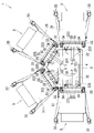
- the powder supply device 1 (hereinafter referred to as the supply device 1) will be described with reference to FIGS. 1 to 4.
- the supply device 1 includes a main body 2, a plurality of stockers 3 connected to the main body 2 to store the powder P inside, and a dust collector 4, and further has an open upper portion for measuring the powder P. It is configured to include a container 5 and a measuring instrument 6.
- the main body 2 includes a main body portion 21 and a gantry 22 that supports the main body portion 21, and has a structure in which the stocker 3 can be attached to and detached from the gantry portion 22.
- the main body 21 has a control unit 211, and the control unit 211 controls the supply of powder P by the supply unit 32, which will be described later, by connecting the main body 2 to the stocker 3, and the main body 2 collects the powder P.
- the exhaust unit 42 which will be described later, is controlled.
- the gantry 22 has a hollow inside, and is fitted with a mounting portion 221 on which the main body portion 21 is placed, a leg portion 222, and a guide portion 35 described later when the stocker 3 is inserted into the main body 2.
- the guide receiving portion 223 and the like are included.
- the gantry 22 further has a fastening member 2221 which is a member capable of fastening the anchoring portion 4122 of the dust collecting portion 4 described later, and the anchoring member 2221 is installed on the leg portion 222 and the gantry 22 is installed. It extends toward the inside of the.
- the height at which the anchoring member 2221 is installed is variable and adjustable.
- a measuring instrument 6 and a container 5 mounted on the measuring instrument 6 and a dust collecting unit 4 are arranged inside the gantry 22 so that the powder P can be stored.
- the dust collecting unit 4 has a fastening unit 4122 that can be anchored to the fastening member 2221 on the side portion 412 of the dust collecting unit 4, which will be described later.
- the dust collecting portion 4 is anchored to the leg portion 222 by the fastening portion 4122 and the fastening member 2221, and is arranged above the container 5 placed on the measuring instrument 6. There is a gap 7 (see FIGS. 1 and 4) between the dust collecting portion 4 and the container 5, and air flows into the inside of the dust collecting portion 4 through the gap 7.
- the stocker 3 includes a charging port 31 capable of charging the powder P inside the stocker 3, a supply port 32, and a supply unit 32 for supplying the powder P stored inside the stocker 3 from the supply port 321.
- the powder P stored in the stocker 3 is supplied from the supply port 321 via the supply unit 32.
- the supply unit 32 of this embodiment is a cylindrical screw feeder.
- the stocker 3 further has a plurality of casters 33 including one with a rotation stopper at the bottom, an elastic member 34, and a guide portion 35 to be inserted into the main body 2. The stocker 3 can be moved in any direction by the caster 33.
- a plurality of stockers 3 are arranged radially around the dust collector 4, and are detachably connected to the main body 2.
- a mechanical insertion / removal structure can be exemplified.
- the stocker 3 is pushed into the main body 2, the guide portion 35 is inserted into the main body 2, and the stocker 3 is attached to the main body 2.
- the stocker 3 is pulled out from the main body 2, the guide portion 35 is pulled away from the main body 2, and the stocker 3 is separated from the main body 2.
- the guide portion 35 is inserted into the main body 2 and is fitted with the guide receiving portion 223.
- the elastic member 34 is a member that has elasticity and cushions an impact by elastic deformation, is located outside the guide portion 35, and is in contact with the main body 2 when the stocker 3 is attached to the main body 2. .. When the stocker 3 receives an unexpected impact from the outside, the elastic member 34 can absorb the impact and prevent the stocker 3 itself from coming into contact with the main body 2 and being damaged.
- the supply unit 32 has a structure that allows it to be inserted into and removed from the notch 4121 of the dust collection unit 4, which will be described later, and is arranged so that the central axis Y of the supply unit 32 faces the center of the dust collection unit 4.
- the stocker 3 When the stocker 3 is attached to the main body 2 in a state where the vicinity of the tip of the supply unit 32 including the supply port 321 is inserted into the inside of the gantry 22 and the supply unit 32 is inserted through the notch 4121, the stocker 3 is attached to the main body 2.
- the 321 is located inside the first region A, which will be described later, and above the upper opening of the container 5.
- the other portion of the supply unit 32 is located in the internal space of the stocker 3, and the powder P stored in the stocker 3 is supplied to the inside of the stocker 32 from the opening of the stocker 32.
- the stocker 3 can be replaced with another stocker 3, it becomes easy to switch the type of powder P to be supplied to the container 5. Since the stocker 3 can be detached from the main body 2, maintenance can be performed with the stocker 3 detached from the main body 2, and the maintainability of the supply device 1 is improved. For example, if the supply unit 32 fails, repair and replacement is easy.
- the dust collecting unit 4 has a casing 41, an exhaust unit 42, and a filtration member 43.
- the casing 41 is a substantially cylindrical lid-like body including a ceiling 411 and a side portion 412, and the surface facing the ceiling 411 is open.
- the side portion 412 has a notch portion 4121 through which the supply portion 32 is inserted.
- the casing 41 is composed of a casing upper portion 41a including a ceiling 411 and a casing lower portion 41b, and the casing upper portion 41a and the casing lower portion 41b are connected to each other by their respective flanges.
- the exhaust unit 42 of this embodiment is a fan installed on the ceiling 411.
- the installation position of the exhaust unit 42 is not limited to the ceiling 411, and may be any position as long as the drive of the exhaust unit 42 enables the filtration member 43 described later to collect dust inside the first region A described later.
- As the installation position of the other exhaust unit 42 for example, a position of the side unit 412 included in the second region B described later can be mentioned.
- Examples of the exhaust unit 42 include a pump in addition to the fan, but the exhaust unit 42 is not particularly limited and may have an exhaust function.
- the filtration member 43 is installed inside the casing 41 above the notch 4121 and below the ceiling 411.
- the filtration member 43 can collect the powder P.
- the filtration member 43 of the present embodiment is a filter cloth.
- Examples of the filtering member 43 include filter paper in addition to the filter cloth, but the filtering member 43 is not particularly limited and may have a filtering function. Not done.
- the degree of opening and the thickness dimension of the filtration member 43 are not particularly limited as long as the supplied powder P can be collected and the flow rate of air passing through the filtration member 43 does not decrease too much, and the powder P is collected. It can be appropriately changed according to the particle size of the powder P.
- the inside of the casing 41 is defined by the filtration member 43 into a first region A and a second region B.
- the first region A is a region below the filtration member 43.
- the second region B is a region above the filtration member 43, and is a region in which the air inside the second region B is exhausted by the exhaust unit 42 and the air that has passed through the filtration member 43 flows in.
- By driving the exhaust unit 42 air flows into the first region A from the open surface facing the ceiling 411, and the air passes through the filtration member 43 and flows into the second region B to be exhausted. It is discharged to the outside of the casing 41 via the portion 42.
- the supply port 321 When the supply unit 32 is inserted through the notch 4121, the supply port 321 is located inside the first region A.
- the dust generated by the supply of the powder P from the supply port 321 moves toward the filtration member 43 along with the air flowing inside the casing 41, and is collected by the filtration member 43. It is possible to prevent deterioration of the working environment due to the generation of dust due to the supply of the powder P.
- the dust collecting unit 4 is arranged above the container 5 placed on the measuring instrument 6. By collecting the dust by the dust collecting unit 4, it is possible to prevent the dust generated by the supply of the powder P from the supply port 321 from adhering to the inner and outer surfaces of the container 5.
- the dust collecting portion 4 is further located above the notch portion 4121 and below the filtering member 43, and has a receiving member 44 that receives the powder P falling from the filtering member 43.
- the powder P dropped from the filtering member 43 is held inside the receiving member 44 (see FIGS. 3 and 4).
- the receiving member 44 of the present embodiment is a circular dish-shaped member having an opening 441 with an opening at the upper side.
- the receiving member 44 preferably has a trumpet shape, for example, in which the opening 441 expands upward. This makes it possible to improve the effect of receiving the powder P falling from the filtration member 43.
- the shape of the receiving member 44 is not particularly limited as long as it has an opening 441 and can receive the powder P falling from the filtering member 43.
- a rectangular parallelepiped, a circular body, an ellipsoid, a polygonal body, etc., in which the opening 441 faces upward can be mentioned.
- the size of the receiving member 44 is not particularly limited as long as it is large enough to receive the powder P falling from the filtering member 43, but it is possible to prevent interference with other members such as the casing 41 and to prevent the inside of the casing 41.
- the size is also determined from the viewpoint of preventing a decrease in the flow rate of the air flowing through the casing.
- the material of the receiving member 44 is not particularly limited, and an existing material can be appropriately used depending on the characteristics of the powder P.
- existing metal materials such as thermosetting resin, thermoplastic resin, and stainless steel can be used.
- the measuring instrument 6 can measure the weight of the powder P supplied from the supply device 1 and stored in the container 5. By connecting the main body 2 and the measuring instrument 6 with a cable (not shown), the main body 2 can be used from the stocker 3 according to the weight of the powder P stored in the container 5 measured by the measuring instrument 6. It is also possible to control the supply flow rate of the supplied powder P.
- a measuring instrument 6 having a conveyor capable of transporting the container 5 on the upper portion thereof can also be adopted. By adopting such a measuring instrument 6, the container 5 can be easily transported and installed. Examples of the conveyor include a roller conveyor and a belt conveyor.
- the supply device 1 can prevent the above-mentioned dust from adhering to the outer surface and the inner surface of the container 5, and can control the supply flow rate of the powder P supplied from the stocker 3 by the above-mentioned main body 2. Therefore, it is possible to supply the powder P having a predetermined weight from the stocker 3 to the container 5 with high accuracy.
- the supply device 1 has a structure in which the size (width dimension) of the gap 7 between the dust collecting portion 4 and the container 5 can be adjusted by adjusting the anchoring position of the dust collecting portion 4 on the leg portion 222.
- the flow velocity of the air flowing from the outside of the casing 41 into the inside of the first region A by the drive of the exhaust portion 42 changes according to the size of the gap 7.
- the size of the gap 7 can be appropriately determined according to the particle size of the powder P to be supplied.
- the method of adjusting the size of the gap 7 is not particularly limited.
- a method of adjusting the height of the measuring instrument 6 and the like can be mentioned.
- the operation procedure of the supply device 1 will be explained.
- the dust collector 4 is installed.
- the size of the gap 7 is determined in consideration of the particle size of the powder P to be supplied, the anchoring position of the dust collecting portion 4 is determined from the heights of the container 5 and the measuring instrument 6, and the dust collecting portion 4 is anchored to the leg portion 222.
- the number of stockers 3 to be mounted on the main body 2 is arbitrary, and the number of stockers 3 to be mounted can be determined in consideration of the type, amount, and the like of the powder P to be supplied.
- the timing of charging the powder P stored inside the stocker 3 into the stocker 3 may be any time before the powder P is supplied, but from the viewpoint of operability, after the powder P is charged into the stocker 3, the stocker 3 is charged. It is preferable to attach 3 to the main body 2.
- the control unit 211 of the main body 2 Operate the control unit 211 of the main body 2 to supply the powder P from the stocker 3 mounted on the main body 2.
- the exhaust unit 42 is driven, flows into the inside of the casing 41 from the gap 7, passes through the first region A, the filtration member 43, the second region B, and the exhaust unit 42 in this order, and the casing 41 A flow F of air exhausted to the outside (see FIGS. 3 and 4) is generated. Since the dust generated by the supply of the powder P from the stocker 3 moves toward the filtration member 43 by the air flowing inside the casing 41, the dust can be collected by the filtration member 43.
- the exhaust unit 42 takes a predetermined time after the supply of the powder P from the stocker 3 to the container 5 is stopped. Stop after the lapse of time. Therefore, the exhaust unit 42 is driven while the powder P is being supplied. This makes it possible to prevent dust from being generated after the exhaust unit 42 is stopped.
- the supply of the powder P from the stocker 3 may be started and stopped by repeating an arbitrary number of times depending on the situation of the supply work. At that time, the exhaust unit 42 is driven at the start of the first supply of the powder P from the stocker 3, and is stopped after a predetermined time has elapsed after all of the repeated supply of the powder P is completed. This makes it possible to prevent dust from being generated after the exhaust unit 42 is stopped.
- each stocker 3 supplies the powder P one by one in order.
- the exhaust unit 42 is driven at the start of supply from the first stocker 3 for supplying the powder P, and for a predetermined time after the supply from the last stocker 3 for supplying the powder P is completed. Stop after the lapse of time. Also in this case, it is possible to prevent dust from being generated after the exhaust unit 42 is stopped.
- the powder supply process is completed, the container 5 is carried out, and a new container 5 is installed. The following powder supply process is performed.
- the stocker 3 is separated from the main body 2.
- the supply device 1 can collect dust generated when the powder P is supplied from the side by the supply unit 32, can prevent deterioration of the working environment, and saves space. , It is a simple structure. Further, it is possible to prevent the powder P that has fallen from the filtration member 43 from flowing out to the outside of the dust collecting unit 4, and it is possible to efficiently control the supply unit 32 and the exhaust unit 42, so that the powder P can be controlled. The weight can be measured accurately. It is also possible to adjust the flow velocity of the air flowing into the dust collecting portion 4 according to the particle size of the powder P to be supplied.
- the present invention is not limited to the above-described embodiment, and modifications and the like can be added within a range that does not deviate from the technical idea of the present invention. It will be included in the technical scope.
- the number of stockers 3 attached to the main body 2 is four in the above embodiment, but an appropriate number such as 1, 2, 3, 5, ... Can be adopted.
- the dust collecting unit 4 is used to measure the weight of the powder P supplied to the container 5, but it can also be applied to powder processing equipment for other purposes.
- Powder supply device 2 ... Main body 21 ... Main body 211 ... Control unit 22 ... Casing 221 ... Mounting unit 222 ... Legs 2221 ... For fastening Member 223 ... Guide receiving part 3 ... Stocker 31 ... Input port 32 ... Supply part 321 ... Supply port 33 ... Caster 34 ... Elastic member 35 ...
Landscapes
- Engineering & Computer Science (AREA)
- Mechanical Engineering (AREA)
- Physics & Mathematics (AREA)
- General Physics & Mathematics (AREA)
- Quality & Reliability (AREA)
- Filling Or Emptying Of Bunkers, Hoppers, And Tanks (AREA)
- Sampling And Sample Adjustment (AREA)
Priority Applications (5)
| Application Number | Priority Date | Filing Date | Title |
|---|---|---|---|
| JP2022522074A JP7100405B1 (ja) | 2020-11-03 | 2021-11-01 | 粉体供給装置 |
| EP21889164.6A EP4242145B1 (en) | 2020-11-03 | 2021-11-01 | Powder supply device |
| KR1020237009532A KR102863809B1 (ko) | 2020-11-03 | 2021-11-01 | 분체 공급 장치 |
| CN202180067448.3A CN116323445B (zh) | 2020-11-03 | 2021-11-01 | 粉末供给装置 |
| US18/192,148 US12187559B2 (en) | 2020-11-03 | 2023-03-29 | Powder supply device |
Applications Claiming Priority (2)
| Application Number | Priority Date | Filing Date | Title |
|---|---|---|---|
| JP2020184019 | 2020-11-03 | ||
| JP2020-184019 | 2020-11-03 |
Related Child Applications (1)
| Application Number | Title | Priority Date | Filing Date |
|---|---|---|---|
| US18/192,148 Continuation US12187559B2 (en) | 2020-11-03 | 2023-03-29 | Powder supply device |
Publications (1)
| Publication Number | Publication Date |
|---|---|
| WO2022097611A1 true WO2022097611A1 (ja) | 2022-05-12 |
Family
ID=81457267
Family Applications (1)
| Application Number | Title | Priority Date | Filing Date |
|---|---|---|---|
| PCT/JP2021/040292 Ceased WO2022097611A1 (ja) | 2020-11-03 | 2021-11-01 | 粉体供給装置 |
Country Status (6)
| Country | Link |
|---|---|
| US (1) | US12187559B2 (https=) |
| EP (1) | EP4242145B1 (https=) |
| JP (1) | JP7100405B1 (https=) |
| KR (1) | KR102863809B1 (https=) |
| CN (1) | CN116323445B (https=) |
| WO (1) | WO2022097611A1 (https=) |
Families Citing this family (3)
| Publication number | Priority date | Publication date | Assignee | Title |
|---|---|---|---|---|
| USD1051190S1 (en) * | 2022-02-25 | 2024-11-12 | Tsukasa Co., Ltd. | Powder particle feeder for weighing |
| USD1059447S1 (en) * | 2022-02-25 | 2025-01-28 | Tsukasa Co., Ltd. | Powder particle weighing machine |
| JP1729852S (ja) * | 2022-03-29 | 2022-11-15 | 粉粒体計量用供給機 |
Citations (8)
| Publication number | Priority date | Publication date | Assignee | Title |
|---|---|---|---|---|
| JPH0171627U (https=) | 1987-10-30 | 1989-05-12 | ||
| JP3005747U (ja) * | 1994-06-28 | 1995-01-10 | トーエイ工業株式会社 | 集塵機 |
| JP2001130748A (ja) * | 1999-11-02 | 2001-05-15 | Tsukasa Kogyo Kk | 粉粒状物質貯留装置 |
| JP2005263468A (ja) | 2004-03-22 | 2005-09-29 | Fuji Tekku Kk | 粉塵防止機能付ホッパ装置 |
| JP3152723U (ja) * | 2009-04-30 | 2009-08-13 | 二井 愼一郎 | 靴清掃用集塵装置 |
| JP2011042448A (ja) | 2009-08-20 | 2011-03-03 | Toyota Motor Corp | 集塵フード |
| JP2014227302A (ja) * | 2013-05-22 | 2014-12-08 | モレット・ソチエタ・ペル・アツィオーニMORETTO S.p.A. | 粒状材料の空気輸送システムおよびそのようなシステムの制御方法 |
| JP2018122922A (ja) * | 2017-02-03 | 2018-08-09 | トヨタ自動車株式会社 | 粉体供給装置および粉体供給方法 |
Family Cites Families (13)
| Publication number | Priority date | Publication date | Assignee | Title |
|---|---|---|---|---|
| US4699187A (en) * | 1986-10-23 | 1987-10-13 | Dravo Corporation | Dust control in hoppers |
| US5052451A (en) * | 1991-02-26 | 1991-10-01 | Mallinckrodt Specialty Chemicals Company | Dust control apparatus |
| US5573044A (en) * | 1994-09-21 | 1996-11-12 | Mechalas; Emmanuel | Vacuum apparatus for filling bags with particulate material |
| EP0997411A1 (en) * | 1998-10-26 | 2000-05-03 | Tsukasa Industry Co., Ltd. | Powder receiving device |
| JP4161096B2 (ja) * | 2003-05-28 | 2008-10-08 | 株式会社日本製鋼所 | 集合フィーダ |
| GB0508113D0 (en) * | 2005-04-22 | 2005-06-01 | Inbulk Technologies Ltd | Container |
| JP4730780B2 (ja) * | 2006-04-18 | 2011-07-20 | 株式会社リコー | 粉体供給装置及び画像形成装置 |
| US20110083770A1 (en) * | 2008-06-02 | 2011-04-14 | Tharwat Fouad-Fahmi | Powdered Product Unloading and Storage System |
| CN204737444U (zh) * | 2015-06-11 | 2015-11-04 | 上海琥崧智能科技股份有限公司 | 一种移动式反吹扫无尘投料装置 |
| CN105600500B (zh) * | 2015-12-26 | 2018-09-04 | 宜春万申制药机械有限公司 | 一种自动计重喂料装置 |
| JP6920676B2 (ja) * | 2017-04-19 | 2021-08-18 | パナソニックIpマネジメント株式会社 | 微粒子製造装置および微粒子製造方法 |
| CN210594262U (zh) * | 2019-09-04 | 2020-05-22 | 张家港森美瑞机械有限公司 | 真空上料装置 |
| EP4230558A4 (en) * | 2020-10-19 | 2024-08-14 | Tsukasa Co., Ltd. | PARTICULATE MATTER DISTRIBUTION DEVICE |
-
2021
- 2021-11-01 KR KR1020237009532A patent/KR102863809B1/ko active Active
- 2021-11-01 CN CN202180067448.3A patent/CN116323445B/zh active Active
- 2021-11-01 JP JP2022522074A patent/JP7100405B1/ja active Active
- 2021-11-01 EP EP21889164.6A patent/EP4242145B1/en active Active
- 2021-11-01 WO PCT/JP2021/040292 patent/WO2022097611A1/ja not_active Ceased
-
2023
- 2023-03-29 US US18/192,148 patent/US12187559B2/en active Active
Patent Citations (8)
| Publication number | Priority date | Publication date | Assignee | Title |
|---|---|---|---|---|
| JPH0171627U (https=) | 1987-10-30 | 1989-05-12 | ||
| JP3005747U (ja) * | 1994-06-28 | 1995-01-10 | トーエイ工業株式会社 | 集塵機 |
| JP2001130748A (ja) * | 1999-11-02 | 2001-05-15 | Tsukasa Kogyo Kk | 粉粒状物質貯留装置 |
| JP2005263468A (ja) | 2004-03-22 | 2005-09-29 | Fuji Tekku Kk | 粉塵防止機能付ホッパ装置 |
| JP3152723U (ja) * | 2009-04-30 | 2009-08-13 | 二井 愼一郎 | 靴清掃用集塵装置 |
| JP2011042448A (ja) | 2009-08-20 | 2011-03-03 | Toyota Motor Corp | 集塵フード |
| JP2014227302A (ja) * | 2013-05-22 | 2014-12-08 | モレット・ソチエタ・ペル・アツィオーニMORETTO S.p.A. | 粒状材料の空気輸送システムおよびそのようなシステムの制御方法 |
| JP2018122922A (ja) * | 2017-02-03 | 2018-08-09 | トヨタ自動車株式会社 | 粉体供給装置および粉体供給方法 |
Non-Patent Citations (1)
| Title |
|---|
| See also references of EP4242145A4 |
Also Published As
| Publication number | Publication date |
|---|---|
| CN116323445A (zh) | 2023-06-23 |
| EP4242145B1 (en) | 2025-01-29 |
| EP4242145C0 (en) | 2025-01-29 |
| EP4242145A1 (en) | 2023-09-13 |
| KR20230051588A (ko) | 2023-04-18 |
| EP4242145A4 (en) | 2024-03-13 |
| JP7100405B1 (ja) | 2022-07-13 |
| JPWO2022097611A1 (https=) | 2022-05-12 |
| US20230227277A1 (en) | 2023-07-20 |
| US12187559B2 (en) | 2025-01-07 |
| KR102863809B1 (ko) | 2025-09-23 |
| CN116323445B (zh) | 2025-10-31 |
Similar Documents
| Publication | Publication Date | Title |
|---|---|---|
| JP7100405B1 (ja) | 粉体供給装置 | |
| EP2631016B1 (en) | Cylindrical dedusting apparatus | |
| CN1083545A (zh) | 把粉末镀到工件上的方法和设备 | |
| CN115485220B (zh) | 粉粒体供给装置 | |
| US9126308B2 (en) | Shot-processing apparatus | |
| JPWO2013186939A1 (ja) | ショット処理装置 | |
| CN106457519B (zh) | 喷丸加工装置以及喷丸加工装置列 | |
| US9962741B2 (en) | Compact dedusting apparatus with remote discharge | |
| JP2020022951A (ja) | コンパクトな除塵装置用の計量装置 | |
| EP3542913B1 (en) | Dedusting apparatus | |
| JPWO2022097611A5 (https=) | ||
| JP6627952B2 (ja) | 分級機構 | |
| CN118594990B (zh) | 一种矿石物料的色选装置 | |
| JPH09113435A (ja) | バグフィルターの粉塵保持量の測定装置 | |
| JP3179338B2 (ja) | ブラスト加工装置 | |
| JP7146172B2 (ja) | 異物除去装置及び異物除去装置を備えたブラスト加工装置 | |
| KR20070081444A (ko) | 파우더 충진장치 | |
| JPH07289998A (ja) | 微粉研磨材に混在する異物の分離方法並びに微粉研磨材に混在する異物及び粉塵の分離方法及びそれらの分離装置 | |
| KR200423775Y1 (ko) | 파우더 이송장치 | |
| JP7178176B2 (ja) | 分離排出型のコンパクトな異物除去装置 | |
| CN210071593U (zh) | 粉尘环境模拟设备和粉尘传输装置 | |
| US1207794A (en) | Grading and transferring mechanism for granular material. | |
| JP2017055671A (ja) | 茶生葉洗浄装置 | |
| JP2000079921A (ja) | フレキシブルコンテナーバッグ開袋装置 | |
| JPH04132998A (ja) | 放射性廃棄物の除染装置 |
Legal Events
| Date | Code | Title | Description |
|---|---|---|---|
| ENP | Entry into the national phase |
Ref document number: 2022522074 Country of ref document: JP Kind code of ref document: A |
|
| 121 | Ep: the epo has been informed by wipo that ep was designated in this application |
Ref document number: 21889164 Country of ref document: EP Kind code of ref document: A1 |
|
| ENP | Entry into the national phase |
Ref document number: 20237009532 Country of ref document: KR Kind code of ref document: A |
|
| NENP | Non-entry into the national phase |
Ref country code: DE |
|
| ENP | Entry into the national phase |
Ref document number: 2021889164 Country of ref document: EP Effective date: 20230605 |
|
| WWG | Wipo information: grant in national office |
Ref document number: 202180067448.3 Country of ref document: CN |