EP4242145B1 - Powder supply device - Google Patents
Powder supply device Download PDFInfo
- Publication number
- EP4242145B1 EP4242145B1 EP21889164.6A EP21889164A EP4242145B1 EP 4242145 B1 EP4242145 B1 EP 4242145B1 EP 21889164 A EP21889164 A EP 21889164A EP 4242145 B1 EP4242145 B1 EP 4242145B1
- Authority
- EP
- European Patent Office
- Prior art keywords
- powder
- dust collection
- stocker
- collection unit
- filtering member
- Prior art date
- Legal status (The legal status is an assumption and is not a legal conclusion. Google has not performed a legal analysis and makes no representation as to the accuracy of the status listed.)
- Active
Links
Images



Classifications
-
- B—PERFORMING OPERATIONS; TRANSPORTING
- B65—CONVEYING; PACKING; STORING; HANDLING THIN OR FILAMENTARY MATERIAL
- B65G—TRANSPORT OR STORAGE DEVICES, e.g. CONVEYORS FOR LOADING OR TIPPING, SHOP CONVEYOR SYSTEMS OR PNEUMATIC TUBE CONVEYORS
- B65G69/00—Auxiliary measures taken, or devices used, in connection with loading or unloading
- B65G69/18—Preventing escape of dust
- B65G69/185—Preventing escape of dust by means of non-sealed systems
- B65G69/186—Preventing escape of dust by means of non-sealed systems with aspiration means
-
- B—PERFORMING OPERATIONS; TRANSPORTING
- B65—CONVEYING; PACKING; STORING; HANDLING THIN OR FILAMENTARY MATERIAL
- B65B—MACHINES, APPARATUS OR DEVICES FOR, OR METHODS OF, PACKAGING ARTICLES OR MATERIALS; UNPACKING
- B65B1/00—Packaging fluent solid material, e.g. powders, granular or loose fibrous material, loose masses of small articles, in individual containers or receptacles, e.g. bags, sacks, boxes, cartons, cans, or jars
- B65B1/28—Controlling escape of air or dust from containers or receptacles during filling
-
- B—PERFORMING OPERATIONS; TRANSPORTING
- B65—CONVEYING; PACKING; STORING; HANDLING THIN OR FILAMENTARY MATERIAL
- B65B—MACHINES, APPARATUS OR DEVICES FOR, OR METHODS OF, PACKAGING ARTICLES OR MATERIALS; UNPACKING
- B65B1/00—Packaging fluent solid material, e.g. powders, granular or loose fibrous material, loose masses of small articles, in individual containers or receptacles, e.g. bags, sacks, boxes, cartons, cans, or jars
- B65B1/30—Devices or methods for controlling or determining the quantity or quality or the material fed or filled
- B65B1/36—Devices or methods for controlling or determining the quantity or quality or the material fed or filled by volumetric devices or methods
-
- B—PERFORMING OPERATIONS; TRANSPORTING
- B65—CONVEYING; PACKING; STORING; HANDLING THIN OR FILAMENTARY MATERIAL
- B65G—TRANSPORT OR STORAGE DEVICES, e.g. CONVEYORS FOR LOADING OR TIPPING, SHOP CONVEYOR SYSTEMS OR PNEUMATIC TUBE CONVEYORS
- B65G65/00—Loading or unloading
- B65G65/30—Methods or devices for filling or emptying bunkers, hoppers, tanks, or like containers, of interest apart from their use in particular chemical or physical processes or their application in particular machines, e.g. not covered by a single other subclass
- B65G65/32—Filling devices
-
- B—PERFORMING OPERATIONS; TRANSPORTING
- B65—CONVEYING; PACKING; STORING; HANDLING THIN OR FILAMENTARY MATERIAL
- B65G—TRANSPORT OR STORAGE DEVICES, e.g. CONVEYORS FOR LOADING OR TIPPING, SHOP CONVEYOR SYSTEMS OR PNEUMATIC TUBE CONVEYORS
- B65G65/00—Loading or unloading
- B65G65/30—Methods or devices for filling or emptying bunkers, hoppers, tanks, or like containers, of interest apart from their use in particular chemical or physical processes or their application in particular machines, e.g. not covered by a single other subclass
- B65G65/34—Emptying devices
- B65G65/40—Devices for emptying otherwise than from the top
-
- G—PHYSICS
- G03—PHOTOGRAPHY; CINEMATOGRAPHY; ANALOGOUS TECHNIQUES USING WAVES OTHER THAN OPTICAL WAVES; ELECTROGRAPHY; HOLOGRAPHY
- G03G—ELECTROGRAPHY; ELECTROPHOTOGRAPHY; MAGNETOGRAPHY
- G03G15/00—Apparatus for electrographic processes using a charge pattern
- G03G15/06—Apparatus for electrographic processes using a charge pattern for developing
- G03G15/08—Apparatus for electrographic processes using a charge pattern for developing using a solid developer, e.g. powder developer
- G03G15/0822—Arrangements for preparing, mixing, supplying or dispensing developer
- G03G15/0877—Arrangements for metering and dispensing developer from a developer cartridge into the development unit
- G03G15/0879—Arrangements for metering and dispensing developer from a developer cartridge into the development unit for dispensing developer from a developer cartridge not directly attached to the development unit
-
- G—PHYSICS
- G03—PHOTOGRAPHY; CINEMATOGRAPHY; ANALOGOUS TECHNIQUES USING WAVES OTHER THAN OPTICAL WAVES; ELECTROGRAPHY; HOLOGRAPHY
- G03G—ELECTROGRAPHY; ELECTROPHOTOGRAPHY; MAGNETOGRAPHY
- G03G15/00—Apparatus for electrographic processes using a charge pattern
- G03G15/06—Apparatus for electrographic processes using a charge pattern for developing
- G03G15/08—Apparatus for electrographic processes using a charge pattern for developing using a solid developer, e.g. powder developer
- G03G15/0896—Arrangements or disposition of the complete developer unit or parts thereof not provided for by groups G03G15/08 - G03G15/0894
- G03G15/0898—Arrangements or disposition of the complete developer unit or parts thereof not provided for by groups G03G15/08 - G03G15/0894 for preventing toner scattering during operation, e.g. seals
-
- B—PERFORMING OPERATIONS; TRANSPORTING
- B65—CONVEYING; PACKING; STORING; HANDLING THIN OR FILAMENTARY MATERIAL
- B65G—TRANSPORT OR STORAGE DEVICES, e.g. CONVEYORS FOR LOADING OR TIPPING, SHOP CONVEYOR SYSTEMS OR PNEUMATIC TUBE CONVEYORS
- B65G2201/00—Indexing codes relating to handling devices, e.g. conveyors, characterised by the type of product or load being conveyed or handled
- B65G2201/02—Articles
- B65G2201/0235—Containers
-
- B—PERFORMING OPERATIONS; TRANSPORTING
- B65—CONVEYING; PACKING; STORING; HANDLING THIN OR FILAMENTARY MATERIAL
- B65G—TRANSPORT OR STORAGE DEVICES, e.g. CONVEYORS FOR LOADING OR TIPPING, SHOP CONVEYOR SYSTEMS OR PNEUMATIC TUBE CONVEYORS
- B65G2201/00—Indexing codes relating to handling devices, e.g. conveyors, characterised by the type of product or load being conveyed or handled
- B65G2201/04—Bulk
-
- B—PERFORMING OPERATIONS; TRANSPORTING
- B65—CONVEYING; PACKING; STORING; HANDLING THIN OR FILAMENTARY MATERIAL
- B65G—TRANSPORT OR STORAGE DEVICES, e.g. CONVEYORS FOR LOADING OR TIPPING, SHOP CONVEYOR SYSTEMS OR PNEUMATIC TUBE CONVEYORS
- B65G2201/00—Indexing codes relating to handling devices, e.g. conveyors, characterised by the type of product or load being conveyed or handled
- B65G2201/04—Bulk
- B65G2201/042—Granular material
Definitions
- the present invention relates to a powder supply device, and more particularly relates to a powder supply device having a dust collection unit to collect powdery dust released when powder is supplied.
- powdery dust Upon putting powder down into a filling container or measuring container, powdery dust is released depending on the particle size of the powder.
- the powdery dust may give a harmful influence on the human body.
- the powdery dust which spreads around a working place may deteriorate a surrounding visibility and soil the working place where a powder supply operation is held. This deteriorates the working environment, and thus likely leads to human errors such as mistakes during confirming processes, mistakes during operations of equipments or the like.
- Patent Literature 1 discloses a dust collection hood which is placed to surround a gap between a first container to accommodate powder and a second container arranged to be positioned under the first container.
- the dust collection hood has an upper side in which an upper opening portion is provided to supply the powder, and has a lateral side in which a lateral opening portion is provided to perform a working operation for the first container.
- the dust collection hood further has a plurality of dust collection openings provided to suck the powdery dust released during a powder supplying operation, and has a flow straightener means which is provided to vertically extend down from the upper opening portion to a lower proximity of the lateral opening portion, in order to straighten an aerial flow toward the dust collection openings from the upper opening portion and the lateral opening portion.
- Patent Literature 2 discloses a hopper device provided to throw powder into a container through a powder supply port.
- the hopper device has a hopper portion, a throwing hole and an exhaust hole provided to be in communication with the throwing hole.
- the hopper portion has a dust sucking hole which is arranged to be in juxtaposition with the exhaust hole.
- the hopper device further has a dust sucking and collecting device which sucks the powdery dust through the dust sucking hole to collect the sucked powdery dust in order to provide the hopper device with a dust-preventive function.
- Patent Literature 3 discloses a dust collection device for use in a powder measurement device in which a powder supply hole, through which powder is dropped into a measurement container placed on a measurement instrument, is provided above the measurement instrument.
- the dust collection device has a floor portion on which the measurement instrument is placed, and a ceiling portion which is placed to oppose the floor portion in an upper-and-lower relationship.
- One of the floor portion or the ceiling portion has a substantially annular air-outlet formed in a manner to surround both the powder supply hole and the measurement instrument so as to blow out an aerial flow.
- the other of the floor portion or the ceiling portion has a suction hole to draw the aerial flow blown out through the air outlet.
- Document EP 0997411 A1 discloses a powder receiving device comprising a housing having a loading chamber with a loading opening and a powder loading hopper.
- Patent Literatures 1 and 2 are structured in a manner to connect the gap between the first container and the second container, in order to collect the powdery dust which is generated when powder is put downward from the first container, such as a flexible container bag or a hopper, placed in a upper site into the second container placed in a lower site.
- This structure is not suited for a powder supply device such as a belt conveyor or a screw conveyor which supplies powder from a lateral side.
- the dust collection hood according to Patent Literature 1 is used in cooperation with a dust collecting device, and cannot be used alone.
- the hopper device with the dust-preventive function according to Patent Literature 2 has the dust sucking and collecting device in addition to the hopper portion, and the hopper portion cannot be used alone as mentioned above. Accordingly, the devices of Patent Literatures 1, 2 need the dust collection device which is discretely set from a place in which the powdery dust is collected. This resultantly makes the powder supply device larger, and a larger space is needed to place the power supply device.
- the device according to Patent Literature 3 has a structure in which an air outlet duct communicated with a blower and a dust collection duct communicated with a dust collecting device are provided above and below the powder supply hole. This makes the powder supply device larger and more complicated, and a larger space is needed to place the power supply device as is the case with the devices of Patent Literatures 1, 2.
- a powder supply device having a main body; a plurality of stockers to be connected to the main body and to reserve powder therein; and a dust collection unit.
- Said stocker has a charge port through which said powder is to be charged into said stocker, and a supplier which has a supply port and which supplies said powder reserved inside said stocker through the supply port.
- Said dust collection unit has a casing, an exhauster and a filtering member.
- Said casing includes a ceiling portion and a lateral side portion, with a side opposing said ceiling portion being opened to form a lid-shaped configuration.
- Said lateral side portion has a notched portion into which said supplier is to be inserted.
- Said filtering member is provided inside said casing and is positioned above the notched portion and below the ceiling portion in order to collect said powder.
- Said casing has an inner space divided into a first region and a second region by the filtering member.
- Said first region is an area below said filtering member.
- Said second region is an area above said filtering member.
- Said second region is an area which permits said exhauster to exhaust air inside said second region and permits an entry of air passing through said filtering member.
- the powder is supplied to the first region through a lateral side of the casing by means of the supplier which is inserted into the notched portion.
- the powder falls under the influence of the gravity, and is exhausted outside the casing through the opened side which opposes the ceiling portion.
- the powdery dust released in the first region moves upward due to the exhauster which forms an air flow from the first region to the second region, and the powdery dust is collected by the filtering member. Therefore, the powder supply device has the dust collection unit suited to a situation in which the powder is supplied from a lateral side by means of the supplier. This obviates the need to connect to a discrete blower or the like, so as to be space saving with a simplified structure.
- the dust collection unit has a receiving member provided to receive the powder falling down from the filtering member, and the receiving member is placed above the notched portion and below the filtering member. According to this structure, even when the collected powder falls down from the filtering member, it is possible to receive the falling powder by the receiving member. Therefore, this makes it possible to prevent the powder falling down from the filtering member from flowing out of the casing.
- said plurality of stockers is radially placed around said dust collection unit, and said stocker has a structure to be detachably connected to the main body, and said supplier has a structure to be detachably inserted into said notched portion, with a central axis of said supplier being directed toward a center of said dust collection unit.
- the dust collection unit can collect the powdery dust released when the powder is supplied from the plurality of stockers. It is possible to remove the stockers from the main body and the dust collection unit. This makes it possible to simplify the operation upon exchanging the powder supplied from the powder supply device with another powder. Further, it is possible to improve a maintainability of the powder supply device.
- said dust collection unit is placed above a container with an opened upper side and for measuring the powder, and said main body has a controller to control the supplier to adjust the supply of said powder and further to control an activation of said exhauster.
- said main body has a controller to control the supplier to adjust the supply of said powder and further to control an activation of said exhauster.
- a gap between the dust collection unit and the container it is preferable to provide a gap between the dust collection unit and the container, and a size of said gap is adjustable. According to this structure, it is possible to adjust a speed of air flowing into the first region from an outside of the casing.
- powder includes any of granule and a mixture of powder and granule in addition to powder. Usage of the powder may be for food, medicine, civil engineering, architecture, semiconductor or the like, and is not restricted.
- supply the powder from the supply port means to send out the powder outside from the stockers through the supply port.
- exhaust means to discharge inner gas from inside to outside.
- exhaust is represented by a fan by way of illustration. However, any means is available as far as it can discharge air as illustratively represented by a pump or the like.
- the "filtering member” is illustratively represented by a filter cloth, however, other means such as filter paper, etc. are adoptable as far as the air or other gaseous material can pass through the filtering means and the filtering means can collect powder.
- the phrase of "collected by the filtering member” means that the powder remains inside the filtering member or is retained on a surface of the filtering member without passing through the filtering member when the powder flows toward the filtering member.
- the "supplier” is illustratively represented by a screw conveyor or a screw feeder, however, other instruments such as vibrating feeder, belt conveyor, etc. are available as far as the supplier has a transport function for the powder.
- the "receiving member” is illustratively represented by a box-like body, a dish-like body, etc., with an opened upper side, and has a structure capable of receiving and retaining the powder inside.
- the "powdery dust” means fine particulates of the powder floating or drifting in the air.
- the "dust collection” means to collect the powdery dust in one place.
- the present invention it becomes possible to collect the powdery dust released when the powder is supplied from a lateral side, while at the same time, it becomes possible to supply the powder with a space-saving and simplified device.
- the supply device 1 has a main body 2, a plurality of stockers 3 for reserving powder P therein and to be connected to the main body 2, and a dust collection unit 4.
- the supply device 1 further has a container 5 for measuring the powder P, having an opened upper side, and a measurement instrument 6.
- the main body 2 has a main body portion 21 and a stand frame 22 provided to support the main body portion 21, and the stocker 3 is detachably connected to the stand frame 22.
- the main body portion 21 has a controller 211, which controls a supplier 32 (described later) to adjust a supply of the powder P, with the main body 2 being connected to the stocker 3, and controls an exhauster 42 (also described later) , with the main body 2 being connected to the dust collection unit 4.
- These controls are manually feasible or automatically operable by a predetermined setting.
- the stand frame 22 is hollow inside and includes a pedestal portion 221 provided to place the main body portion 21, and leg portions 222, and further includes guide receiving members 223 into which guides 35 (described later) are to be fit when the stocker 3 is inserted into the main body 2.
- the stand frame 22 further has fixing members 2221 which can fix fixed members 4122 (described later) provided on the dust collection unit 4.
- the fixing member 2221 is mounted on the leg portion 222 and extends toward an inner side of the stand frame 22. The height of the mounting of the fixing member 2221 is changeable and adjustable.
- the dust collection unit 4 has the fixed member 4122 which is to be fixed to the fixing member 2221.
- the dust collection unit 4 is fixed to the leg portions 222 by the fixed members 4122 and fixing members 2221, and placed above the container 5 set on the measurement instrument 6. Between the dust collection unit 4 and the container 5, a gap 7 is provided through which air flows to be introduced into the dust collection unit 4 as shown in Figs. 1 and 4 .
- the stocker 3 includes a charge port 31 through which the powder P is to be charged therein, and the supplier 32 having a supply port 321.
- the supplier 32 supplies the powder P reserved inside the stocker 3 from the supply port 321.
- the powder P reserved inside the stocker 3 is supplied from the supply port 321 through the supplier 32.
- the supplier 32 in this embodiment is a cylindrical screw feeder.
- the stocker 3 further has a plurality of casters 33, one or more of the casters 33 being with a rotary stopper, at the bottom.
- the stocker 3 further has elastic members 34 and the guides 35 which are to be inserted into the main body 2.
- the stockers 3 are movable in any direction with the use of the casters 33.
- the plurality of stockers 3 (four stockers herein) is radially positioned around the dust collection unit 4, and the stocker 3 is detachably connected to the main body 2.
- the structure may be illustratively represented by a mechanical insertion and drawing structure.
- the elastic member 34 has an elasticity to absorb an impact due to an elastic deformation, and is positioned outside of the guide 35 to be in contact with the main body 2 when the stocker 3 is mounted to the main body 2.
- the elastic member 34 absorbs the impact so as to prevent the stocker 3 itself from contacting against the main body 2, thus avoiding the stocker 3 to get damaged.
- the supplier 32 has a structure to be detachably inserted into a notched portion 4121 (described later) of the dust collection unit 4, and is set, with the central axis Y of the supplier 32 being directed toward the center of the dust collection unit 4.
- the supply port 321 is placed inside a first region A (described later), and positioned above an upper opening of the container 5.
- Other parts of the supplier 32 reside within an inner space of the stocker 3.
- the powder P reserved inside the stocker 3 is supplied into the supplier 32 through an opening of the supplier 32.
- the stocker 3 Upon mounting the stocker 3 to the main body 2, the stocker 3 is moved to the position in which the powder P is supplied. Then, together with the guide 35 of the stocker 3, the vicinity of the leading end of the supplier 32 including supply port 321 is brought inside the stand frame 22 of the main body 2 to make the guide 35 fit into the guide receiving member 223. Thereafter, the rotary stopper of the caster 33 is operated to fixedly place the stocker 3 in the position, and the main body 2 and the stocker 3 are connected via a cable wire (not shown) to complete the mounting. On the other hand, upon separating the stocker 3 from the main body 2, the cable wire which connects the stocker 3 to the main body 2 is taken out.
- the rotary stopper of the caster 33 is cancelled to pull the stocker 3 out of the main body 2 so as to relocate the stocker 3 from the place in which the powder P is supplied.
- the stocker 3 is attached to and detached from the main body 2 with ease to make the mounted stocker 3 readily exchangeable with other stockers 3. Namely, the individual stockers 3 are mounted to the main body 2 in an exchangeable relationship with other stockers 3.
- the stocker 3 Since the stocker 3 is easily exchangeable with other stockers 3, it is possible to easily exchange one kind of the powder P with other kind powder which is to be supplied to the container 5. With the stocker 3 detachably mounted to the main body 2, it is possible to check and adjust the stocker 3, with the stocker 3 taken out of the main body 2, so as to ameliorate a maintainability of the supply device 1. For example, when the supplier 32 would be in trouble, its repair and replacement would be carried out with ease.
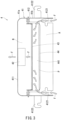
- the dust collection unit 4 has a casing 41 and a filtering member 43 in addition to the exhauster 42.
- the casing 41 is generally cylindrical in shape, and has a side portion 412 and a ceiling portion 411, with a side opposing said ceiling portion 411 being opened to form a lid-shaped configuration.
- the side portion 412 has the notched portion 4121 into which the supplier 32 is to be inserted.
- the casing 41 has a lower casing portion 41b and an upper casing portion 41a which includes the ceiling portion 411.
- Each of the lower casing portion 41b and the upper casing portion 41a has a flange, and they are structurally connected to each other via the flanges.
- the exhauster 42 is a fan which is placed on the ceiling portion 411.
- the location to place the exhauster 42 is not limited to the ceiling portion 411, any location is available as far as the filtering member 43 (described later) can collect the powdery dust inside the first region A (described later) by activation of the exhauster 42.
- a location on the side portion 412 inside a second region B (described later) is applicable.
- a pump is applicable other than the fan, however, the exhauster 42 is not limited in particular, and any means is applicable as far as it has an exhaust function.
- the filtering member 43 is located inside the casing 41 above the notched portion 4121 and under the ceiling portion 411.
- the filtering member 43 can collect the powder P.
- the filtering member 43 is a filter cloth.
- a filter paper can be adopted, for example.
- the filtering member 43 is not limited in particular. Any material is applicable as far as it has a filtering function.
- a mesh opening and thickness of the filtering member 43 is not limited in particular, and appropriately changeable depending on the particle diameter of the powder P to be collected as far as the filtering member 43 is able to collect the supplied powder P, and as far as the flowing quantity of the air passing through the filtering member 43 is not excessively lowered.
- the casing 41 has an inner space divided into the first region A and the second region B via the filtering member 43.
- the first region A is an area under the filtering member 43.
- the second region B is an area above the filtering member 43, and inner air in the second region B is exhausted by the exhauster 42, while an air flow is permitted to enter the second region B when the air flow passes through the filtering member 43.
- the exhauster 42 is activated, air is taken into the first region A through the opened side which opposes the ceiling portion 411. Then, the air passes through the filtering member 43 to flow into the second region B, so as to be exhausted outside the casing 41 through the exhauster 42.
- the supply port 321 is positioned inside the first region A. At the time of supplying the powder P from the supply port 321, released is the powdery dust, which flows toward the filtering member 43 in accompany with the air flow inside the casing 41, and is collected by the filtering member 43. This makes it possible to prevent the working environment from deteriorating when the powdery dust is released in accompany with the supply of the powder P.
- the dust collection unit 4 is situated above the container 5 which is placed on the measurement instrument 6. Since the powdery dust is collected by the dust collection unit 4, it is possible to prevent the powdery dust from adhering to the inner and outer surfaces of the container 5, even when the powdery dust is released in accompany with the supply of the powder P through the supply port 321.
- the dust collection unit 4 further has a receiving member 44 which is positioned above the notched portion 4121 and under the filtering member 43, and receives the powder P falling down from the filtering member 43. As shown in Figs. 3 and 4 , the powder P fallen from the filtering member 43 is retained inside the receiving member 44.
- the receiving member 44 is formed into a circular dish-shaped configuration, having an opening 441 on an upper side.
- the receiving member 44 preferably has the opening 441, an upper portion of which flares out like a trumpet-like configuration. This makes it possible to improve an effect to receive the powder P falling from the filtering member 43.
- the configuration of the receiving member 44 is not limited in particular. Any configuration would be usable for the receiving member 44 as far as the receiving member 44 has the opening 441 and can receive the powder P which falls from the filtering member 43.
- the configuration of the receiving member 44 may be a rectangular parallelepiped body, a circular body, an ellipsoidal body a polygonal body, etc., each with the opening 441 directed upward.
- the scale of the receiving member 44 is not limited in particular as far as the scale is enough to receive the powder P falling from the filtering member 43.
- the scale would be determined from the viewpoint to avoid an interference with other members such as the casing 41 or the like, and also from the viewpoint to prevent a decrease of the air flow inside the casing 41.
- the material of the receiving member 44 is not limited in particular.
- Existing materials for the receiving member 44 can be appropriately usable depending on the character of the powder P.
- an existing thermosetting resin, a thermoplastic resin, a metallic material such as stainless steel or the like is usable for the receiving member 44.
- the measurement instrument 6 is able to measure a weight of the powder P which is supplied from the supply device 1 and reserved in the container 5.
- the main body 2 can control the flowing quantity of the powder P supplied from the stocker 3 in accordance with the weight of the powder P reserved in the container 5 and measured by the measurement instrument 6.
- a conveyor may be installed in order to make the container 5 transferable. By adopting such a measurement instrument 6 as mentioned above, the installation and the transfer of the container 5 would be easily carried out.
- a roller conveyor, a belt conveyor or the like is applicable.
- the supply device 1 it is possible to prevent the powdery dust from adhering to the inside or outside of the container 5, while at the same time, it is possible to control the flowing quantity of the powder P supplied from the stocker 3 by the main body 2. This enables the supply device 1 to supply the powder P of a predetermined weight from the stocker 3 to the container 5 with a high precision.
- the supply device 1 has such a structure as to make a gap 7 adjustable (in width) between the dust collection unit 4 and the container 5 by adjusting a fixing position of the dust collection unit 4 to the leg portion 222.
- the air flow speed changes depending on the size of the gap 7.
- the size of the gap 7 may be determined appropriately in accordance with the particle diameter of the supplied powder P.
- a method to adjust the size of the gap 7 is not limited in particular.
- the method is exemplified by adjusting the fixed position of the dust collection unit 4 to the leg portion 222, or by adjusting a height of the measurement instrument 6.
- Procedures how to operate the supply device 1 is described as follows: First, the dust collection unit 4 is installed. The dust collection unit 4 is fixed to the leg portion 222 after determining the fixing position. The size of the gap 7 is determined by considering the particle diameter of the supplied powder P, and then the fixing position is determined by considering the gap size, the height of the container 5 and the measurement instrument 6.
- the stocker 3 is mounted to the main body 2.
- the number of the stockers 3 mounted to the main body 2 is discretionally determined. By considering the sort and quantity of the supplied powder P, it would be possible to determine the number of the stockers 3 to be mounted.
- the timing to charge the powder P into the stocker 3 to reserve the powder P therein, is acceptable at any time before the powder P is supplied from the stocker 3. However, it is preferable to mount the stocker 3 to the main body 2 after the powder P is charged into the stocker 3 considering operability.
- the powder P is supplied from the stocker 3 which is mounted to the main body 2.
- the exhauster 42 is activated to generate an air flow F which flows into the casing 41 from the gap 7, and passes through the first region A, the filtering member 43, the second region B and the exhauster 42 in turn to be exhausted outside the casing 41 as shown in Figs. 3 and 4 . Since the powdery dust released upon supplying the powder P from the stocker 3, flows toward the filtering member 43 due to the air flowing inside the casing 41, it is possible to collect the powdery dust by the filtering member 43.
- the exhauster 42 Upon manually or automatically ceasing the supply of the powder P from the stocker 3, the exhauster 42 is deactivated to stop after a predetermined elapse of time period from the supply cessation of the powder P from the stocker 3 to the container 5. This means that the exhauster 42 is kept activated while the powder P is being supplied. This prevents the powdery dust from being released after the exhauster 42 is deactivated to stop.
- Start and cessation of supplying the powder P from the stocker 3 may be repeatedly carried out in any number of time depending on the working condition.
- the exhauster 42 is activated at the time when the powder P is firstly supplied from the stocker 3, and the exhauster 42 is ceased after a predetermined elapse of time period from an end of all the repetitive supply of the powder P. This prevents the powdery dust from being released after the exhauster 42 is deactivated to stop.
- each of the stockers 3 individually supplies the powder P in turn one by one.
- the exhauster 42 is activated at the time when the supply of the powder P from the first stocker 3 is started, and the exhauster 42 ceases after a predetermined elapse of time period from an end of the supply of the powder P from the last stocker 3. This makes it possible to prevent the powdery dust from being released after the exhauster 42 is ceased.
- the powder supply procedure ends and the container 5 is transferred outside. After the container 5 is transferred outside, another container 5 is installed to carry out a next powder supply procedure.
- the stocker 3 is detached to be separated from the main body 2.
- the supply device 1 makes it possible to collect the powdery dust released when the powder P is supplied from the lateral side by the supplier 32, so as to prevent the deterioration of the working environment with a space-saving and simplified structure. Further, the supply device 1 prevents the fallen powder P from flowing outside the dust collection unit 4 when the powder P falls from the filtering member 43. Furthermore, the supply device 1 makes it possible to efficiently control the supplier 32 and the exhauster 42, so as to measure the weight of the powder P with a high precision. The supply device 1 also makes it possible to adjust the air flow speed flowing into the dust collection unit 4 depending on the particle diameter of the supplied powder P.
Landscapes
- Engineering & Computer Science (AREA)
- Mechanical Engineering (AREA)
- Physics & Mathematics (AREA)
- General Physics & Mathematics (AREA)
- Quality & Reliability (AREA)
- Filling Or Emptying Of Bunkers, Hoppers, And Tanks (AREA)
- Sampling And Sample Adjustment (AREA)
Applications Claiming Priority (2)
| Application Number | Priority Date | Filing Date | Title |
|---|---|---|---|
| JP2020184019 | 2020-11-03 | ||
| PCT/JP2021/040292 WO2022097611A1 (ja) | 2020-11-03 | 2021-11-01 | 粉体供給装置 |
Publications (4)
| Publication Number | Publication Date |
|---|---|
| EP4242145A1 EP4242145A1 (en) | 2023-09-13 |
| EP4242145A4 EP4242145A4 (en) | 2024-03-13 |
| EP4242145B1 true EP4242145B1 (en) | 2025-01-29 |
| EP4242145C0 EP4242145C0 (en) | 2025-01-29 |
Family
ID=81457267
Family Applications (1)
| Application Number | Title | Priority Date | Filing Date |
|---|---|---|---|
| EP21889164.6A Active EP4242145B1 (en) | 2020-11-03 | 2021-11-01 | Powder supply device |
Country Status (6)
| Country | Link |
|---|---|
| US (1) | US12187559B2 (https=) |
| EP (1) | EP4242145B1 (https=) |
| JP (1) | JP7100405B1 (https=) |
| KR (1) | KR102863809B1 (https=) |
| CN (1) | CN116323445B (https=) |
| WO (1) | WO2022097611A1 (https=) |
Families Citing this family (3)
| Publication number | Priority date | Publication date | Assignee | Title |
|---|---|---|---|---|
| USD1051190S1 (en) * | 2022-02-25 | 2024-11-12 | Tsukasa Co., Ltd. | Powder particle feeder for weighing |
| USD1059447S1 (en) * | 2022-02-25 | 2025-01-28 | Tsukasa Co., Ltd. | Powder particle weighing machine |
| JP1729852S (ja) * | 2022-03-29 | 2022-11-15 | 粉粒体計量用供給機 |
Family Cites Families (21)
| Publication number | Priority date | Publication date | Assignee | Title |
|---|---|---|---|---|
| US4699187A (en) * | 1986-10-23 | 1987-10-13 | Dravo Corporation | Dust control in hoppers |
| JPH056499Y2 (https=) | 1987-10-30 | 1993-02-19 | ||
| US5052451A (en) * | 1991-02-26 | 1991-10-01 | Mallinckrodt Specialty Chemicals Company | Dust control apparatus |
| JP3005747U (ja) * | 1994-06-28 | 1995-01-10 | トーエイ工業株式会社 | 集塵機 |
| US5573044A (en) * | 1994-09-21 | 1996-11-12 | Mechalas; Emmanuel | Vacuum apparatus for filling bags with particulate material |
| EP0997411A1 (en) * | 1998-10-26 | 2000-05-03 | Tsukasa Industry Co., Ltd. | Powder receiving device |
| JP3328619B2 (ja) * | 1999-11-02 | 2002-09-30 | ツカサ工業株式会社 | 粉粒状物質貯留装置 |
| JP4161096B2 (ja) * | 2003-05-28 | 2008-10-08 | 株式会社日本製鋼所 | 集合フィーダ |
| JP2005263468A (ja) | 2004-03-22 | 2005-09-29 | Fuji Tekku Kk | 粉塵防止機能付ホッパ装置 |
| GB0508113D0 (en) * | 2005-04-22 | 2005-06-01 | Inbulk Technologies Ltd | Container |
| JP4730780B2 (ja) * | 2006-04-18 | 2011-07-20 | 株式会社リコー | 粉体供給装置及び画像形成装置 |
| US20110083770A1 (en) * | 2008-06-02 | 2011-04-14 | Tharwat Fouad-Fahmi | Powdered Product Unloading and Storage System |
| JP3152723U (ja) * | 2009-04-30 | 2009-08-13 | 二井 愼一郎 | 靴清掃用集塵装置 |
| JP2011042448A (ja) | 2009-08-20 | 2011-03-03 | Toyota Motor Corp | 集塵フード |
| ITPD20130142A1 (it) * | 2013-05-22 | 2014-11-23 | Moretto Spa | Sistema di trasporto pneumatico di materiale granulare e metodo di controlllo di tale sistema |
| CN204737444U (zh) * | 2015-06-11 | 2015-11-04 | 上海琥崧智能科技股份有限公司 | 一种移动式反吹扫无尘投料装置 |
| CN105600500B (zh) * | 2015-12-26 | 2018-09-04 | 宜春万申制药机械有限公司 | 一种自动计重喂料装置 |
| JP2018122922A (ja) * | 2017-02-03 | 2018-08-09 | トヨタ自動車株式会社 | 粉体供給装置および粉体供給方法 |
| JP6920676B2 (ja) * | 2017-04-19 | 2021-08-18 | パナソニックIpマネジメント株式会社 | 微粒子製造装置および微粒子製造方法 |
| CN210594262U (zh) * | 2019-09-04 | 2020-05-22 | 张家港森美瑞机械有限公司 | 真空上料装置 |
| EP4230558A4 (en) * | 2020-10-19 | 2024-08-14 | Tsukasa Co., Ltd. | PARTICULATE MATTER DISTRIBUTION DEVICE |
-
2021
- 2021-11-01 KR KR1020237009532A patent/KR102863809B1/ko active Active
- 2021-11-01 CN CN202180067448.3A patent/CN116323445B/zh active Active
- 2021-11-01 JP JP2022522074A patent/JP7100405B1/ja active Active
- 2021-11-01 EP EP21889164.6A patent/EP4242145B1/en active Active
- 2021-11-01 WO PCT/JP2021/040292 patent/WO2022097611A1/ja not_active Ceased
-
2023
- 2023-03-29 US US18/192,148 patent/US12187559B2/en active Active
Also Published As
| Publication number | Publication date |
|---|---|
| CN116323445A (zh) | 2023-06-23 |
| WO2022097611A1 (ja) | 2022-05-12 |
| EP4242145C0 (en) | 2025-01-29 |
| EP4242145A1 (en) | 2023-09-13 |
| KR20230051588A (ko) | 2023-04-18 |
| EP4242145A4 (en) | 2024-03-13 |
| JP7100405B1 (ja) | 2022-07-13 |
| JPWO2022097611A1 (https=) | 2022-05-12 |
| US20230227277A1 (en) | 2023-07-20 |
| US12187559B2 (en) | 2025-01-07 |
| KR102863809B1 (ko) | 2025-09-23 |
| CN116323445B (zh) | 2025-10-31 |
Similar Documents
| Publication | Publication Date | Title |
|---|---|---|
| US12187559B2 (en) | Powder supply device | |
| KR100256865B1 (ko) | 분말을 공작물에 적용하는 방법 및 장치 | |
| CN115485220B (zh) | 粉粒体供给装置 | |
| EP3029436B1 (en) | Combination scale | |
| EP2157018A2 (en) | Automatic medicine packing machine with cleaning device | |
| EP3441147A1 (en) | Powder supplying device for a powder coating installation | |
| KR20140137323A (ko) | 과립 재료의 공압 운송 시스텝 및 해당 시스템의 제어 방법 | |
| WO2008093179A1 (en) | Device for emptying powder bags for powder spray coating apparatus | |
| JP4877253B2 (ja) | ノズル回収装置、ノズル回収装置を備えた実装装置および回収ノズルのメンテナンス方法 | |
| US12466671B2 (en) | Powder supply device | |
| JPWO2022097611A5 (https=) | ||
| CN113941513A (zh) | To自动分拣整理设备 | |
| CN114084678B (zh) | 一种用于输送片剂的负压式吸入器 | |
| CN113019999B (zh) | Ic接收料装置 | |
| US3044218A (en) | Abrasive grit marking machine | |
| JP7504546B2 (ja) | 組合せ秤 | |
| JPH0629696Y2 (ja) | 物品供給装置 | |
| JP6144767B2 (ja) | 部品実装機 | |
| KR200423775Y1 (ko) | 파우더 이송장치 | |
| RU2775283C1 (ru) | Установка для заполнения контейнера сыпучим материалом, в частности песком | |
| CN215901616U (zh) | 一种自动配料设备 | |
| KR20100075112A (ko) | 부품 실장기용 폐 테이프 수거장치 | |
| WO2024024017A1 (ja) | リール作業装置 | |
| KR200422087Y1 (ko) | 파우더 이송장치 | |
| JP2015074536A (ja) | 穀物吸引搬送装置 |
Legal Events
| Date | Code | Title | Description |
|---|---|---|---|
| STAA | Information on the status of an ep patent application or granted ep patent |
Free format text: STATUS: THE INTERNATIONAL PUBLICATION HAS BEEN MADE |
|
| PUAI | Public reference made under article 153(3) epc to a published international application that has entered the european phase |
Free format text: ORIGINAL CODE: 0009012 |
|
| STAA | Information on the status of an ep patent application or granted ep patent |
Free format text: STATUS: REQUEST FOR EXAMINATION WAS MADE |
|
| 17P | Request for examination filed |
Effective date: 20230223 |
|
| AK | Designated contracting states |
Kind code of ref document: A1 Designated state(s): AL AT BE BG CH CY CZ DE DK EE ES FI FR GB GR HR HU IE IS IT LI LT LU LV MC MK MT NL NO PL PT RO RS SE SI SK SM TR |
|
| DAV | Request for validation of the european patent (deleted) | ||
| DAX | Request for extension of the european patent (deleted) | ||
| A4 | Supplementary search report drawn up and despatched |
Effective date: 20240209 |
|
| RIC1 | Information provided on ipc code assigned before grant |
Ipc: B65G 69/18 20060101ALI20240206BHEP Ipc: G03G 15/08 20060101ALI20240206BHEP Ipc: B65G 65/40 20060101ALI20240206BHEP Ipc: B65G 65/32 20060101AFI20240206BHEP |
|
| GRAP | Despatch of communication of intention to grant a patent |
Free format text: ORIGINAL CODE: EPIDOSNIGR1 |
|
| STAA | Information on the status of an ep patent application or granted ep patent |
Free format text: STATUS: GRANT OF PATENT IS INTENDED |
|
| INTG | Intention to grant announced |
Effective date: 20240917 |
|
| GRAS | Grant fee paid |
Free format text: ORIGINAL CODE: EPIDOSNIGR3 |
|
| GRAA | (expected) grant |
Free format text: ORIGINAL CODE: 0009210 |
|
| STAA | Information on the status of an ep patent application or granted ep patent |
Free format text: STATUS: THE PATENT HAS BEEN GRANTED |
|
| AK | Designated contracting states |
Kind code of ref document: B1 Designated state(s): AL AT BE BG CH CY CZ DE DK EE ES FI FR GB GR HR HU IE IS IT LI LT LU LV MC MK MT NL NO PL PT RO RS SE SI SK SM TR |
|
| REG | Reference to a national code |
Ref country code: GB Ref legal event code: FG4D |
|
| REG | Reference to a national code |
Ref country code: CH Ref legal event code: EP |
|
| REG | Reference to a national code |
Ref country code: DE Ref legal event code: R096 Ref document number: 602021025689 Country of ref document: DE |
|
| REG | Reference to a national code |
Ref country code: IE Ref legal event code: FG4D |
|
| U01 | Request for unitary effect filed |
Effective date: 20250206 |
|
| U07 | Unitary effect registered |
Designated state(s): AT BE BG DE DK EE FI FR IT LT LU LV MT NL PT RO SE SI Effective date: 20250212 |
|
| PG25 | Lapsed in a contracting state [announced via postgrant information from national office to epo] |
Ref country code: RS Free format text: LAPSE BECAUSE OF FAILURE TO SUBMIT A TRANSLATION OF THE DESCRIPTION OR TO PAY THE FEE WITHIN THE PRESCRIBED TIME-LIMIT Effective date: 20250429 |
|
| PG25 | Lapsed in a contracting state [announced via postgrant information from national office to epo] |
Ref country code: PL Free format text: LAPSE BECAUSE OF FAILURE TO SUBMIT A TRANSLATION OF THE DESCRIPTION OR TO PAY THE FEE WITHIN THE PRESCRIBED TIME-LIMIT Effective date: 20250129 |
|
| PG25 | Lapsed in a contracting state [announced via postgrant information from national office to epo] |
Ref country code: ES Free format text: LAPSE BECAUSE OF FAILURE TO SUBMIT A TRANSLATION OF THE DESCRIPTION OR TO PAY THE FEE WITHIN THE PRESCRIBED TIME-LIMIT Effective date: 20250129 |
|
| PG25 | Lapsed in a contracting state [announced via postgrant information from national office to epo] |
Ref country code: IS Free format text: LAPSE BECAUSE OF FAILURE TO SUBMIT A TRANSLATION OF THE DESCRIPTION OR TO PAY THE FEE WITHIN THE PRESCRIBED TIME-LIMIT Effective date: 20250529 Ref country code: NO Free format text: LAPSE BECAUSE OF FAILURE TO SUBMIT A TRANSLATION OF THE DESCRIPTION OR TO PAY THE FEE WITHIN THE PRESCRIBED TIME-LIMIT Effective date: 20250429 |
|
| PG25 | Lapsed in a contracting state [announced via postgrant information from national office to epo] |
Ref country code: HR Free format text: LAPSE BECAUSE OF FAILURE TO SUBMIT A TRANSLATION OF THE DESCRIPTION OR TO PAY THE FEE WITHIN THE PRESCRIBED TIME-LIMIT Effective date: 20250129 |
|
| PG25 | Lapsed in a contracting state [announced via postgrant information from national office to epo] |
Ref country code: GR Free format text: LAPSE BECAUSE OF FAILURE TO SUBMIT A TRANSLATION OF THE DESCRIPTION OR TO PAY THE FEE WITHIN THE PRESCRIBED TIME-LIMIT Effective date: 20250430 |
|
| PG25 | Lapsed in a contracting state [announced via postgrant information from national office to epo] |
Ref country code: SM Free format text: LAPSE BECAUSE OF FAILURE TO SUBMIT A TRANSLATION OF THE DESCRIPTION OR TO PAY THE FEE WITHIN THE PRESCRIBED TIME-LIMIT Effective date: 20250129 |
|
| PG25 | Lapsed in a contracting state [announced via postgrant information from national office to epo] |
Ref country code: CZ Free format text: LAPSE BECAUSE OF FAILURE TO SUBMIT A TRANSLATION OF THE DESCRIPTION OR TO PAY THE FEE WITHIN THE PRESCRIBED TIME-LIMIT Effective date: 20250129 |
|
| PG25 | Lapsed in a contracting state [announced via postgrant information from national office to epo] |
Ref country code: SK Free format text: LAPSE BECAUSE OF FAILURE TO SUBMIT A TRANSLATION OF THE DESCRIPTION OR TO PAY THE FEE WITHIN THE PRESCRIBED TIME-LIMIT Effective date: 20250129 |
|
| U20 | Renewal fee for the european patent with unitary effect paid |
Year of fee payment: 5 Effective date: 20251006 |
|
| PLBE | No opposition filed within time limit |
Free format text: ORIGINAL CODE: 0009261 |
|
| STAA | Information on the status of an ep patent application or granted ep patent |
Free format text: STATUS: NO OPPOSITION FILED WITHIN TIME LIMIT |
|
| 26N | No opposition filed |
Effective date: 20251030 |
|
| PGFP | Annual fee paid to national office [announced via postgrant information from national office to epo] |
Ref country code: GB Payment date: 20251117 Year of fee payment: 5 |