WO2022097585A1 - 管継手、押輪および管の接合方法 - Google Patents
管継手、押輪および管の接合方法 Download PDFInfo
- Publication number
- WO2022097585A1 WO2022097585A1 PCT/JP2021/040119 JP2021040119W WO2022097585A1 WO 2022097585 A1 WO2022097585 A1 WO 2022097585A1 JP 2021040119 W JP2021040119 W JP 2021040119W WO 2022097585 A1 WO2022097585 A1 WO 2022097585A1
- Authority
- WO
- WIPO (PCT)
- Prior art keywords
- seal member
- pipe
- receiving port
- push ring
- tapered surface
- Prior art date
Links
- 238000000034 method Methods 0.000 title claims description 16
- 238000003780 insertion Methods 0.000 claims abstract description 167
- 230000037431 insertion Effects 0.000 claims abstract description 167
- 238000007789 sealing Methods 0.000 claims description 39
- 230000002093 peripheral effect Effects 0.000 claims description 37
- 238000005452 bending Methods 0.000 description 5
- 238000013459 approach Methods 0.000 description 2
- 239000000463 material Substances 0.000 description 1
- 239000011347 resin Substances 0.000 description 1
- 229920005989 resin Polymers 0.000 description 1
Images


Classifications
-
- F—MECHANICAL ENGINEERING; LIGHTING; HEATING; WEAPONS; BLASTING
- F16—ENGINEERING ELEMENTS AND UNITS; GENERAL MEASURES FOR PRODUCING AND MAINTAINING EFFECTIVE FUNCTIONING OF MACHINES OR INSTALLATIONS; THERMAL INSULATION IN GENERAL
- F16L—PIPES; JOINTS OR FITTINGS FOR PIPES; SUPPORTS FOR PIPES, CABLES OR PROTECTIVE TUBING; MEANS FOR THERMAL INSULATION IN GENERAL
- F16L21/00—Joints with sleeve or socket
- F16L21/02—Joints with sleeve or socket with elastic sealing rings between pipe and sleeve or between pipe and socket, e.g. with rolling or other prefabricated profiled rings
- F16L21/04—Joints with sleeve or socket with elastic sealing rings between pipe and sleeve or between pipe and socket, e.g. with rolling or other prefabricated profiled rings in which sealing rings are compressed by axially-movable members
-
- F—MECHANICAL ENGINEERING; LIGHTING; HEATING; WEAPONS; BLASTING
- F16—ENGINEERING ELEMENTS AND UNITS; GENERAL MEASURES FOR PRODUCING AND MAINTAINING EFFECTIVE FUNCTIONING OF MACHINES OR INSTALLATIONS; THERMAL INSULATION IN GENERAL
- F16L—PIPES; JOINTS OR FITTINGS FOR PIPES; SUPPORTS FOR PIPES, CABLES OR PROTECTIVE TUBING; MEANS FOR THERMAL INSULATION IN GENERAL
- F16L21/00—Joints with sleeve or socket
- F16L21/02—Joints with sleeve or socket with elastic sealing rings between pipe and sleeve or between pipe and socket, e.g. with rolling or other prefabricated profiled rings
- F16L21/03—Joints with sleeve or socket with elastic sealing rings between pipe and sleeve or between pipe and socket, e.g. with rolling or other prefabricated profiled rings placed in the socket before connection
-
- F—MECHANICAL ENGINEERING; LIGHTING; HEATING; WEAPONS; BLASTING
- F16—ENGINEERING ELEMENTS AND UNITS; GENERAL MEASURES FOR PRODUCING AND MAINTAINING EFFECTIVE FUNCTIONING OF MACHINES OR INSTALLATIONS; THERMAL INSULATION IN GENERAL
- F16L—PIPES; JOINTS OR FITTINGS FOR PIPES; SUPPORTS FOR PIPES, CABLES OR PROTECTIVE TUBING; MEANS FOR THERMAL INSULATION IN GENERAL
- F16L37/00—Couplings of the quick-acting type
- F16L37/08—Couplings of the quick-acting type in which the connection between abutting or axially overlapping ends is maintained by locking members
- F16L37/084—Couplings of the quick-acting type in which the connection between abutting or axially overlapping ends is maintained by locking members combined with automatic locking
- F16L37/088—Couplings of the quick-acting type in which the connection between abutting or axially overlapping ends is maintained by locking members combined with automatic locking by means of a split elastic ring
-
- F—MECHANICAL ENGINEERING; LIGHTING; HEATING; WEAPONS; BLASTING
- F16—ENGINEERING ELEMENTS AND UNITS; GENERAL MEASURES FOR PRODUCING AND MAINTAINING EFFECTIVE FUNCTIONING OF MACHINES OR INSTALLATIONS; THERMAL INSULATION IN GENERAL
- F16L—PIPES; JOINTS OR FITTINGS FOR PIPES; SUPPORTS FOR PIPES, CABLES OR PROTECTIVE TUBING; MEANS FOR THERMAL INSULATION IN GENERAL
- F16L21/00—Joints with sleeve or socket
- F16L21/08—Joints with sleeve or socket with additional locking means
Definitions
- the present invention relates to a pipe joint in which an insertion port formed in one pipe is inserted into a socket formed in the other pipe, a push ring used for this pipe joint, and a method for joining the pipe.
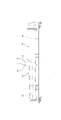
- a pipe joint 110 as shown in FIG. 16 is known.
- the pipe joint 110 is configured as follows.
- the insertion port 102 formed in one tube 101 is inserted into the receiving port 104 formed in the other tube 103.
- a first tapered surface 105 whose diameter is reduced toward the inner side of the receiving port 104 is formed on the inner circumference of the receiving port 104.
- a seal member insertion space 106 is formed over the entire circumference between the first tapered surface 105 and the outer periphery of the insertion port 102.
- An annular seal member 107 that seals between the inner circumference of the receiving port 104 and the outer circumference of the insertion port 102 is inserted into the sealing member insertion space 106.
- the push ring 109 that pushes the seal member 107 from the opening end surface 108 of the receiving port 104 into the sealing member insertion space 106 is fitted outside the insertion port 102 and faces the opening end surface 108 of the receiving port 104 from the outside.
- a receiving port protrusion 111 protruding inward in the pipe radial direction B from the inner circumference of the receiving port 104 is formed over the entire circumference.
- a lock ring 112 is housed in the back side of the receiving port 104 further than the receiving port protrusion 111.
- the insertion port 102 penetrates the lock ring 112, and the insertion port protrusion 113 is formed on the outer periphery of the tip portion of the insertion port 102 over the entire circumference.
- the insertion port protrusion 113 can engage with the lock ring 112 from the back side of the receiving port 104 in the detachment direction 120 of one of the pipes 101. This prevents the insertion port 102 from coming off from the receiving port 104 in the event of an earthquake or the like.
- the push ring 109 is fastened to the receiving port 104 via a plurality of bolts 114 and nuts 115.
- the bolt 114 is inserted into the bolt insertion hole 116 formed in the push ring 109.
- These bolts 114, nuts 115, and bolt insertion holes 116 are formed at predetermined intervals in the pipe circumferential direction G, respectively.
- the push ring 109 is provided with a plurality of protrusions 117. Each of these protrusions 117 is located outside the bolt insertion hole 116 in the pipe radial direction B.
- the seal member 107 has a valve portion 118, which is compressed in the pipe radial direction B and exerts a sealing function, at one end in the insertion direction C.
- the seal member 107 and the push ring 109 are fitted onto one tube 101, the insertion port 102 is inserted into the receiving port 104, centering is performed, and the axial center of one tube 101 is set on the other tube 103. Align with the axis. In this state, the bolt 114 and the nut 115 are tightened, and the seal member 107 is pushed into the seal member insertion space 106 from the opening end surface 108 of the receiving port 104 by the push ring 109.
- the seal member can be reliably pushed into the seal member insertion space by the push ring, the deformation of the push ring can be prevented, and further, the tightening torque of the fastener does not need to be managed. And to provide a method of joining push rings and pipes.
- the insertion port formed in one tube is inserted into the socket formed in the other tube.
- a first tapered surface that shrinks toward the back of the socket is formed on the inner circumference of the socket.
- a sealing member insertion space is formed over the entire circumference between the first tapered surface and the outer periphery of the insertion slot, and an annular sealing member that seals between the inner circumference of the receiving port and the outer periphery of the insertion slot is the sealing member insertion space.
- Inserted in A push ring that pushes the seal member into the seal member insertion space from the opening end face of the socket is fitted outside the insertion slot and faces the opening end face of the socket from the outside.
- the push ring is fastened to the socket via multiple fasteners
- the sealing member has a valve portion at one end in the insertion direction, which is compressed in the pipe radial direction and exerts a sealing function.
- a guide portion that guides the valve portion of the seal member from the opening end surface of the receptacle to the seal member insertion space is formed on the inner circumference of the receptacle.
- the guide portion has a second tapered surface whose diameter is reduced toward the back of the receiving port.
- the second tapered surface is formed between the open end surface of the socket and the first tapered surface in the pipe axis direction. It is characterized in that the inclination angle of the second tapered surface with respect to the tube axis is larger than the inclination angle of the first tapered surface with respect to the tube axis.
- the valve portion of the sealing member is provided with the opening end surface of the receiving port by the second tapered surface of the guide portion. Since the seal member is guided to the seal member insertion space, the seal member can be reliably pushed into the seal member insertion space by the push ring. As a result, it is not necessary to tighten the fasteners so that the tightening torques are uniform, management of the tightening torques of the fasteners becomes unnecessary, and the time required for the tightening work of the fasteners can be shortened.
- the valve when the seal member is inserted into the seal member insertion space in a state of being fitted to the insertion port, the valve between the inner circumference and the outer circumference of the valve portion of the seal member in the pipe radial direction. It is preferable that the central portion is located inward in the pipe radial direction with respect to the end portion of the second tapered surface on the opening end surface side of the receiving port.
- the central part of the valve of the seal member is located inside in the pipe radial direction from the end of the second tapered surface, when the push ring is fastened to the receiving port, the fastener is tightened to one side and the seal member is released. Even if the valve portion of the seal member is extended and loosened in the pipe radial direction, the valve portion of the seal member is surely guided from the opening end surface of the receiving port to the seal member insertion space by the second tapered surface of the guide portion.
- the central portion of the valve is the receiving port even in the minimum gap portion. It is preferable that the relationship of being located inside in the pipe radial direction with respect to the end portion of the second tapered surface on the opening end surface side is maintained.
- valve center portion of the seal member is located inside the end portion of the second tapered surface in the pipe radial direction even in the minimum gap portion.
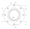
- the push ring is surrounded by a fastener insertion hole through which the fastener is inserted, an annular first protrusion that abuts on the opening end surface of the receiving port, and a first protrusion.
- a recess is provided,
- the first protrusion is formed inside the fastener insertion hole in the pipe radial direction.
- the other end of the seal member in the detachment direction is fitted into the recess of the push ring. It is preferable that the diameter of the end portion of the second tapered surface on the opening end surface side of the receiving port is smaller than the inner diameter of the first protrusion of the push ring.
- a gap surrounded by the inner peripheral surface of the first protrusion, the second tapered surface, and the outer peripheral surface of the sealing member is formed.
- a second protrusion abutting on the open end surface of the receiving port is formed, and the push ring is formed.
- the second protrusion is characterized in that it is formed outside the first protrusion in the radial direction of the pipe.
- the fastener when the fastener is inserted into the fastener insertion hole and the push ring is fastened to the receiving port, even if an excessive fastening force acts on the push ring, the first protrusion and the second protrusion are formed. Since each of them is in contact with the open end surface of the receiving port, it is possible to prevent the push ring from being deformed.
- the first protrusion is formed. Deformation of the push ring can be prevented by contacting the second protrusion with the open end surface of the receiving port.
- a plurality of fastener insertion holes and a plurality of second protrusions are formed at predetermined intervals in the circumferential direction of the pipe, respectively.
- the second protrusion is formed outside the fastener insertion hole in the pipe radial direction.
- On the outer peripheral edge of the push ring a plurality of outer peripheral recesses recessed inward in the pipe radial direction are formed. It is preferable that the outer peripheral recess is inserted between the fastener insertion hole and the fastener insertion hole adjacent to the fastener insertion hole from the outer peripheral edge of the push ring. According to this, since a plurality of outer peripheral recesses are formed on the outer peripheral edge of the push ring, the weight of the push ring can be reduced as compared with the push ring having no outer peripheral recess.
- the width in the pipe radial direction from the inner circumference to the outer circumference of the first protrusion is configured to be equal to or larger than the width in the pipe radial direction from the outer circumference of the first protrusion to the outer peripheral recess. Is preferable. According to this, even if a plurality of outer peripheral recesses are formed on the outer peripheral edge of the push ring, the strength of the push ring can be sufficiently maintained.
- the insertion port formed in one tube is inserted into the socket formed in the other tube.
- a first tapered surface that shrinks toward the back of the socket is formed on the inner circumference of the socket.
- a sealing member insertion space is formed over the entire circumference between the first tapered surface and the outer periphery of the insertion slot, and an annular sealing member that seals between the inner circumference of the receiving port and the outer periphery of the insertion slot is the sealing member insertion space.
- Inserted in A push ring that pushes the seal member into the seal member insertion space from the opening end face of the receiving port is fitted outside the insertion opening and faces the opening end surface of the receiving port from the outside.
- the push ring is fastened to the socket via multiple fasteners and is fastened to the socket.
- the sealing member has a valve portion at one end in the insertion direction, which is compressed in the pipe radial direction and exerts a sealing function.
- a guide portion that guides the valve portion of the seal member from the opening end surface of the receptacle to the seal member insertion space is formed on the inner circumference of the receptacle.
- the guide portion has a second tapered surface whose diameter is reduced toward the back of the receiving port.
- the method of joining this pipe is With the seal member and the push ring fitted to one tube, insert the insertion port into the receiving port of the other tube.
- the other end of the seal member in the detachment direction is fitted into the recess formed in the push ring.
- the valve center portion between the inner circumference and the outer circumference of the valve portion of the sealing member in the pipe radial direction is positioned inward in the pipe radial direction with respect to the end portion on the opening end surface side of the receiving port of the second tapered surface.
- the insertion port is inserted into the receiving port of the other tube.
- a minimum gap portion is generated in which the gap between the outer circumference of the insertion port and the inner circumference of the receiving port is the minimum allowable range, the other end of the seal member is fitted into the recess of the push ring, and even in the minimum gap portion, the valve portion It is preferable that the central portion of the valve is located inward in the pipe radial direction with respect to the end portion on the open end surface side of the receiving port of the second tapered surface.
- the valve portion of the seal member is guided from the opening end surface of the receiving port to the seal member insertion space by the second tapered surface of the guide portion.
- the valve portion of the seal member is sealed from the open end surface of the receptacle by the second tapered surface of the guide portion. Since the seal member is guided to the insertion space, the seal member can be reliably pushed into the seal member insertion space by the push ring. Further, it is not necessary to tighten the fasteners so that the tightening torques are uniform, management of the tightening torques of the fasteners becomes unnecessary, and the time required for the tightening work of the fasteners can be shortened.
- FIG. 3 is a view taken along the line XX in FIG. It is a YY arrow view in FIG. It is sectional drawing which shows the joint method of the pipe in the pipe joint. It is sectional drawing which shows the joint method of the pipe in the pipe joint.
- the same is a partially enlarged cross-sectional view showing a method of joining pipes in a pipe joint, and shows a state when the seal member starts to be inserted into the seal member insertion space.
- the same is a partially enlarged cross-sectional view showing a method of joining pipes in a pipe joint, and shows a state in which the seal member is being inserted into the seal member insertion space.
- the same is a partially enlarged cross-sectional view showing a method of joining pipes in a pipe joint, and shows a state when the seal member is inserted into the seal member insertion space. It is a figure which shows the pipe bent and joined by the pipe joint in the 2nd Embodiment of this invention. It is a cross-sectional view of the lower part of the pipe joint.
- the insertion port 3 formed in one pipe 2 is inserted into the receiving port 5 formed in the other pipe 4. It is composed of.
- a first tapered surface 8, a straight surface 9, a receiving port protrusion 10, and a lock ring accommodating groove 11 are formed on the inner circumference of the receiving port 5.
- the diameter of the first tapered surface 8 is reduced toward the inner side of the receiving port 5.
- the straight surface 9 is parallel to the pipe axis 13 of the pipe 4 and is continuous from the back end portion of the first tapered surface 8 to the back side of the receiving port 5.
- a seal member insertion space 14 is formed over the entire circumference between the first tapered surface 8 and the outer periphery of the insertion port 3.
- An annular seal member 15 that seals between the inner circumference of the receiving port 5 and the outer circumference of the insertion port 3 is inserted into the sealing member insertion space 14.
- the push ring 17 that pushes the seal member 15 from the opening end surface 16 of the receiving port 5 into the sealing member insertion space 14 is fitted outside the insertion opening 3 and faces the opening end surface 16 of the receiving port 5 from the outside.
- the push ring 17 is fastened to the receiving port 5 via a plurality of T-head bolts 19 (an example of a fastener) and a nut 20 (an example of a fastener).
- a plurality of bolt holes 21 through which the T-head bolt 19 is inserted are formed in the receiving port 5.
- the lock ring accommodating groove 11 is formed on the back side of the receiving port 5 with respect to the sealing member insertion space 14.
- the lock ring 22 is accommodated in the lock ring accommodating groove 11.
- the lock ring 22 is a ring having a split structure in which one portion is cut off.
- the lock ring 22 has elasticity such that the width of the cut portion is expanded by expanding the width of the cut portion with a diameter expander (not shown), and the diameter is reduced and returned to the original diameter by removing the diameter expander from the cut portion. are doing.
- the insertion port 3 penetrates the lock ring 22.
- An insertion port protrusion 23 is formed over the entire circumference of the outer periphery of the tip portion of the insertion port 3.
- the insertion port protrusion 23 can engage with the lock ring 22 from the back side of the receiving port 5 in the detaching direction 25 of one of the pipes 2, whereby the insertion opening 3 can be detached from the receiving port 5 in the event of an earthquake or the like. It is prevented from doing.
- the receiving port protrusion 10 projects inward from the inner circumference of the receiving port 5 in the pipe radial direction B, and is formed over the entire circumference between the seal member insertion space 14 and the lock ring accommodating groove 11.
- a centering ring 24 is fitted between the inner circumference of the receiving port protrusion 10 and the outer periphery of the insertion port 3.
- the centering ring 24 is a ring having a split structure in which one portion is cut, and is manufactured of a material such as an elastic resin.
- the seal member 15 is a rubber ring, and has a valve portion 26 having a circular cross section provided at one end in the insertion direction C and a trapezoidal base 27 having a cross section integrally provided with the valve portion 26.
- a valve portion 26 having a circular cross section provided at one end in the insertion direction C and a trapezoidal base 27 having a cross section integrally provided with the valve portion 26.
- the valve portion 26 is compressed in the pipe radial direction B to exhibit the sealing function.
- a guide portion 29 that guides the valve portion 26 of the seal member 15 from the opening end surface 16 of the receptacle 5 to the seal member insertion space 14 is formed on the inner circumference of the receptacle 5.
- the guide portion 29 has a second tapered surface 30 whose diameter is reduced toward the inner side of the receiving port 5.
- the second tapered surface 30 is formed over the entire circumference between the open end surface 16 of the receiving port 5 and the first tapered surface 8 in the pipe axis direction E. As shown in FIG. 1, the inclination angle ⁇ 2 of the second tapered surface 30 with respect to the pipe axis 13 is larger than the inclination angle ⁇ 1 of the first tapered surface 8 with respect to the pipe axis 13.
- the push ring 17 has a plurality of bolt insertion holes 32 (an example of fastener insertion holes) through which T-head bolts 19 are inserted, and a circle that abuts on the opening end surface 16 of the receiving port 5.
- An annular first protrusion 33, a plurality of second protrusions 34 that abut on the opening end surface 16, and a recess 35 surrounded by the first protrusion 33 are provided.
- the first protrusion 33, the second protrusion 34, and the recess 35 are formed on the joint surface side of the push ring 17 facing the opening end surface 16 of the receiving port 5.
- the first protrusion 33 is formed inside the bolt insertion hole 32 in the pipe radial direction B. As shown in FIGS. 1 and 9, the other end of the base portion 27 of the seal member 15 in the detaching direction 25 is fitted into the recess 35 of the push ring 17.
- the bolt insertion hole 32 and the second protrusion 34 are formed at predetermined intervals in the pipe peripheral direction G, respectively. Further, the second protrusion 34 is formed outside the bolt insertion hole 32 in the pipe radial direction B. As shown in FIG. 5, the height h1 of the first protrusion 33 and the height h2 of the second protrusion 34 are the same.
- a plurality of inwardly recessed outer peripheral recesses 37 in the pipe radial direction B are formed on the outer peripheral edge of the push ring 17. As shown in FIGS. 3 and 4, the outer peripheral recess 37 enters between the bolt insertion hole 32 and the bolt insertion hole 32 adjacent to the bolt insertion hole 32 from the outer peripheral edge of the push ring 17.
- the width W1 in the pipe radial direction B from the inner circumference to the outer circumference of the first protrusion 33 is configured to be equal to or larger than the width W2 in the pipe radial direction B from the outer circumference of the first protrusion 33 to the outer peripheral recess 37. There is.
- the inner peripheral surface 33a of the first protrusion 33 of the push ring 17 is a tapered surface whose diameter increases in the insertion direction C. As shown in FIG. 2, the diameter D2 of the end portion 30a of the second tapered surface 30 on the opening end surface 16 side of the receiving port 5 is smaller than the inner diameter D1 of the first protrusion 33 of the push ring 17.
- a gap 39 surrounded by the inner peripheral surface 33a of the first protrusion 33, the second tapered surface 30, and the outer peripheral surface of the base 27 of the sealing member 15 is formed over the entire circumference. Has been done.
- valve center 41 of the valve portion 26 of the seal member 15 is inserted.
- the valve center portion 41 is a center portion between the inner circumference and the outer circumference of the valve portion 26 in the pipe radial direction B.
- the lock ring 22 is accommodated in the lock ring accommodating groove 11, and the width of the cut portion of the lock ring 22 is expanded by using a diameter expander (not shown) to expand the diameter of the lock ring 22.
- the insertion port 3 of one tube 2 is inserted into the receiving port 5 of the other tube 4.
- the lock ring 22 is expanded in diameter by using the diameter expander as described above, the insertion port protrusion 23 passes through the inner circumference of the lock ring 22 from the opening end surface 16 of the receiving port 5. It reaches the back side of the receiving port 5 from the lock ring 22. After that, by removing the diameter expander from the cut portion of the lock ring 22, the diameter of the lock ring 22 is reduced and the lock ring 22 is attached to the outer periphery of the insertion port 3.
- the centering ring 24 is slid in the pipe axis direction E and inserted between the inner circumference of the receiving port protrusion 10 and the outer periphery of the insertion port 3.
- the insertion port 3 is centered with respect to the receiving port 5, and there is almost no deviation between the axis of one tube 2 and the axis of the other tube 4.
- the other end of the base portion 27 of the seal member 15 in the detachment direction 25 is fitted into the recess 35 of the push ring 17, and the T-head bolt 19 is inserted into the bolt hole 21 of the receiving port 5 and the push ring 17.
- the nut 20 is tightened to the T-head bolt 19 and the seal member 15 is pushed into the seal member insertion space 14 from the opening end surface 16 of the receiving port 5 by the push ring 17.
- valve portion 26 of the seal member 15 is guided from the opening end surface 16 of the receiving port 5 to the seal member insertion space 14 by the second tapered surface 30 of the guide portion 29.
- valve center portion 41 of the seal member 15 is located inside the end portion 30a of the second tapered surface 30 in the pipe radial direction B, the push ring 17 is fastened to the receiving port 5.
- the valve portion 26 is the second tapered surface 30 of the guide portion 29. It is surely guided from the opening end surface 16 of the receiving port 5 to the seal member insertion space 14, and the seal member 15 can be surely pushed into the seal member insertion space 14 by the push ring 17.
- the width W1 from the inner circumference to the outer circumference of the first protrusion 33 is equal to or larger than the width W2 from the outer circumference of the first protrusion 33 to the outer peripheral recess 37. Therefore, even if a plurality of outer peripheral recesses 37 are formed on the outer peripheral edge of the push ring 17, the strength of the push ring 17 can be sufficiently maintained. (Second embodiment)
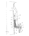
- one tube 2 is joined straight to the other tube 4 without bending, but the second tube described below is described below.
- one pipe 2 may be joined to the other pipe 4 in a state of being bent at a predetermined bending angle ⁇ . At this time, one of the pipes 2 is inclined so that the end portion on the insertion port 3 side is higher than the end portion on the opposite side.
- the structure of the pipe joint 1 for joining the bent pipes 2 and 4 to each other is the same as the structure of the pipe joint 1 in the first embodiment described above (see FIG. 1).
- the centering ring 24 is slid in the pipe axis direction E and inserted between the inner circumference of the receiving port protrusion 10 and the outer periphery of the insertion port 3, and then one of them.
- the pipe 2 is bent with respect to the other pipe 4 at a predetermined bending angle ⁇ .
- the gap between the outer circumference of the insertion port 3 and the inner circumference of the receiving port 5 becomes the minimum allowable range.
- the minimum gap portion 43 is generated in the lower part of the pipe joint 1.
- valve portion 26 of the seal member 15 is guided from the opening end surface 16 of the receiving port 5 to the seal member insertion space 14 by the second tapered surface 30 of the guide portion 29.
- the seal member 15 is also provided in the minimum gap portion 43 as described above. Since the valve center portion 41 of the valve portion 41 is located inside the end portion 30a of the second tapered surface 30 in the pipe radial direction B, the valve portion 26 is provided with the opening end surface of the receiving port 5 by the second tapered surface 30 of the guide portion 29. It is surely guided from 16 to the seal member insertion space 14, and the seal member 15 can be surely pushed into the seal member insertion space 14 by the push ring 17.
Landscapes
- Engineering & Computer Science (AREA)
- General Engineering & Computer Science (AREA)
- Mechanical Engineering (AREA)
- Joints With Sleeves (AREA)
- Joints With Pressure Members (AREA)
Abstract
Description
シール部材107は、挿入方向Cにおける一端部に、管径方向Bにおいて圧縮されてシール機能を発揮するバルブ部118を有している。
上記のような管継手110については日本国の特開2010-286110号公報を参照することができる。
受口奥側ほど縮径する第1のテーパー面が受口の内周に形成され、
第1のテーパー面と挿し口の外周との間にシール部材挿入空間が全周にわたり形成され、受口の内周と挿し口の外周との間をシールする環状のシール部材がシール部材挿入空間に挿入され、
シール部材を受口の開口端面からシール部材挿入空間に押し込む押輪が挿し口に外嵌されて受口の開口端面に外側から対向し、
押輪が複数の締結具を介して受口に締結され、
シール部材は、挿入方向における一端部に、管径方向において圧縮されてシール機能を発揮するバルブ部を有しており、
シール部材のバルブ部を受口の開口端面からシール部材挿入空間に案内する案内部が受口の内周に形成され、
案内部は受口奥側ほど縮径する第2のテーパー面を有し、
第2のテーパー面は、管軸方向において、受口の開口端面と第1のテーパー面との間に形成され、
管軸心に対する第2のテーパー面の傾斜角度が管軸心に対する第1のテーパー面の傾斜角度よりも大きいことを特徴とする。
第1の突部は管径方向において締結具挿通孔よりも内側に形成され、
シール部材の離脱方向における他端部が押輪の凹部に嵌め込まれ、
受口の開口端面側における第2のテーパー面の端部の直径が押輪の第1の突部の内径よりも小さいことが好ましい。
第2の突部は管径方向において第1の突部よりも外側に形成されていることを特徴とする。
第2の突部は管径方向において締結具挿通孔よりも外側に形成され、
押輪の外周縁に、管径方向における内向きに凹んだ複数の外周凹部が形成され、
外周凹部は押輪の外周縁から締結具挿通孔とその隣の締結具挿通孔との間に入り込んでいることが好ましい。
これによると、押輪の外周縁に複数の外周凹部が形成されているため、外周凹部が形成されていない押輪に比べて、押輪を軽量化することができる。
これによると、押輪の外周縁に複数の外周凹部を形成しても、押輪の強度を十分に保つことができる。
受口奥側ほど縮径する第1のテーパー面が受口の内周に形成され、
第1のテーパー面と挿し口の外周との間にシール部材挿入空間が全周にわたり形成され、受口の内周と挿し口の外周との間をシールする環状のシール部材がシール部材挿入空間に挿入され、
シール部材を受口の開口端面からシール部材挿入空間に押し込む押輪が挿し口に外嵌されて受口の開口端面に外側から対向し、
押輪は複数の締結具を介して受口に締結され、
シール部材は、挿入方向における一端部に、管径方向において圧縮されてシール機能を発揮するバルブ部を有し、
シール部材のバルブ部を受口の開口端面からシール部材挿入空間に案内する案内部が受口の内周に形成され、
案内部は受口奥側ほど縮径する第2のテーパー面を有し、
第2のテーパー面が管軸方向において受口の開口端面と第1のテーパー面との間に形成されている管継手における管の接合方法であって、
この管の接合方法は、
シール部材と押輪とを一方の管に外嵌した状態で、挿し口を他方の管の受口に挿入し、
シール部材の離脱方向における他端部を押輪に形成された凹部に嵌め込み、
シール部材のバルブ部の管径方向における内周と外周との間のバルブ中心部を、第2のテーパー面の受口の開口端面側における端部よりも、管径方向において内側に位置させた状態で、締結具を締め込み、押輪でシール部材を受口の開口端面からシール部材挿入空間に押し込むことを特徴とする。
挿し口の外周と受口の内周との隙間が許容範囲の最小となる最小隙間部分が発生した場合、シール部材の他端部を押輪の凹部に嵌め込み、最小隙間部分においても、バルブ部のバルブ中心部を、第2のテーパー面の受口の開口端面側における端部よりも、管径方向において内側に位置させることが好ましい。
(第1の実施の形態)
受口5には、T頭ボルト19が挿通される複数のボルト孔21が形成されている。
第1の突部33と第2の突部34と凹部35とは、受口5の開口端面16に対向する押輪17の接合面側に形成されている。
上記管継手1における管2,4の接合方法を以下に説明する。
その後、拡径器をロックリング22の切断部分から取り外すことによって、ロックリング22が縮径して挿し口3の外周に抱き付く。
(第2の実施の形態)
このように屈曲した管2,4同士を接合する管継手1の構造は、先に説明した第1の実施の形態における管継手1の構造(図1参照)と同じである。
Claims (10)
- 一方の管に形成された挿し口が他方の管に形成された受口内に挿入され、受口奥側ほど縮径する第1のテーパー面が受口の内周に形成され、
第1のテーパー面と挿し口の外周との間にシール部材挿入空間が全周にわたり形成され、受口の内周と挿し口の外周との間をシールする環状のシール部材がシール部材挿入空間に挿入され、
シール部材を受口の開口端面からシール部材挿入空間に押し込む押輪が挿し口に外嵌されて受口の開口端面に外側から対向し、
押輪が複数の締結具を介して受口に締結される管継手であって、
シール部材は、挿入方向における一端部に、管径方向において圧縮されてシール機能を発揮するバルブ部を有しており、
シール部材のバルブ部を受口の開口端面からシール部材挿入空間に案内する案内部が受口の内周に形成され、
案内部は受口奥側ほど縮径する第2のテーパー面を有し、
第2のテーパー面は、管軸方向において、受口の開口端面と第1のテーパー面との間に形成され、
管軸心に対する第2のテーパー面の傾斜角度が管軸心に対する第1のテーパー面の傾斜角度よりも大きいことを特徴とする管継手。 - シール部材が挿し口に外嵌された状態でシール部材挿入空間に挿入される際、シール部材のバルブ部の管径方向における内周と外周との間のバルブ中心部が、受口の開口端面側における第2のテーパー面の端部よりも、管径方向において内側に位置することを特徴とする請求項1に記載の管継手。
- 挿し口の外周と受口の内周との隙間が許容範囲の最小となる最小隙間部分が発生した場合、最小隙間部分においても、バルブ中心部が受口の開口端面側における第2のテーパー面の端部よりも管径方向において内側に位置するという関係が保たれることを特徴とする請求項2に記載の管継手。
- 押輪に、締結具が挿通される締結具挿通孔と、受口の開口端面に当接する円環状の第1の突部と、第1の突部に囲まれた凹部とが設けられ、
第1の突部は管径方向において締結具挿通孔よりも内側に形成され、
シール部材の離脱方向における他端部が押輪の凹部に嵌め込まれ、
受口の開口端面側における第2のテーパー面の端部の直径が押輪の第1の突部の内径よりも小さいことを特徴とする請求項3に記載の管継手。 - 第1の突部の内周面と第2のテーパー面とシール部材の外周面とで囲まれた隙間が形成されていることを特徴とする請求項4に記載の管継手。
- 上記請求項4又は請求項5における管継手に使用される押輪であって、
受口の開口端面に当接する第2の突部が形成され、
第2の突部は管径方向において第1の突部よりも外側に形成されていることを特徴とする押輪。 - 複数の締結具挿通孔と複数の第2の突部とがそれぞれ管周方向において所定間隔をおいて形成され、
第2の突部は管径方向において締結具挿通孔よりも外側に形成され、
押輪の外周縁に、管径方向における内向きに凹んだ複数の外周凹部が形成され、
外周凹部は押輪の外周縁から締結具挿通孔とその隣の締結具挿通孔との間に入り込んでいることを特徴とする請求項6に記載の押輪。 - 第1の突部の内周から外周までの管径方向の幅が第1の突部の外周から外周凹部までの管径方向の幅以上となるように構成されていることを特徴とする請求項7に記載の押輪。
- 一方の管に形成された挿し口が他方の管に形成された受口内に挿入され、受口奥側ほど縮径する第1のテーパー面が受口の内周に形成され、
第1のテーパー面と挿し口の外周との間にシール部材挿入空間が全周にわたり形成され、受口の内周と挿し口の外周との間をシールする環状のシール部材がシール部材挿入空間に挿入され、
シール部材を受口の開口端面からシール部材挿入空間に押し込む押輪が挿し口に外嵌されて受口の開口端面に外側から対向し、
押輪は複数の締結具を介して受口に締結され、
シール部材は、挿入方向における一端部に、管径方向において圧縮されてシール機能を発揮するバルブ部を有し、
シール部材のバルブ部を受口の開口端面からシール部材挿入空間に案内する案内部が受口の内周に形成され、
案内部は受口奥側ほど縮径する第2のテーパー面を有し、
第2のテーパー面が管軸方向において受口の開口端面と第1のテーパー面との間に形成されている管継手における管の接合方法であって、
シール部材と押輪とを一方の管に外嵌した状態で、挿し口を他方の管の受口に挿入し、
シール部材の離脱方向における他端部を押輪に形成された凹部に嵌め込み、シール部材のバルブ部の管径方向における内周と外周との間のバルブ中心部を、第2のテーパー面の受口の開口端面側における端部よりも、管径方向において内側に位置させた状態で、締結具を締め込み、押輪でシール部材を受口の開口端面からシール部材挿入空間に押し込むことを特徴とする管の接合方法。 - 挿し口を他方の管の受口に挿入し、
挿し口の外周と受口の内周との隙間が許容範囲の最小となる最小隙間部分が発生した場合、シール部材の他端部を押輪の凹部に嵌め込み、最小隙間部分においても、バルブ部のバルブ中心部を、第2のテーパー面の受口の開口端面側における端部よりも、管径方向において内側に位置させることを特徴とする請求項9記載の管の接合方法。
Priority Applications (4)
| Application Number | Priority Date | Filing Date | Title |
|---|---|---|---|
| CA3196194A CA3196194A1 (en) | 2020-11-06 | 2021-10-29 | Pipe joint, gland, and method for joining pipes |
| EP21889138.0A EP4239237A4 (en) | 2020-11-06 | 2021-10-29 | PIPE JOINT AND METHOD FOR JOINING A PRESSURE RING AND PIPE |
| CN202180073965.1A CN116490712A (zh) | 2020-11-06 | 2021-10-29 | 管接头、压圈及管的接合方法 |
| US18/034,968 US20230400128A1 (en) | 2020-11-06 | 2021-10-29 | Pipe joint, gland, and method for joining pipes |
Applications Claiming Priority (2)
| Application Number | Priority Date | Filing Date | Title |
|---|---|---|---|
| JP2020-185472 | 2020-11-06 | ||
| JP2020185472A JP2022074980A (ja) | 2020-11-06 | 2020-11-06 | 管継手、押輪および管の接合方法 |
Publications (1)
| Publication Number | Publication Date |
|---|---|
| WO2022097585A1 true WO2022097585A1 (ja) | 2022-05-12 |
Family
ID=81457924
Family Applications (1)
| Application Number | Title | Priority Date | Filing Date |
|---|---|---|---|
| PCT/JP2021/040119 WO2022097585A1 (ja) | 2020-11-06 | 2021-10-29 | 管継手、押輪および管の接合方法 |
Country Status (7)
| Country | Link |
|---|---|
| US (1) | US20230400128A1 (ja) |
| EP (1) | EP4239237A4 (ja) |
| JP (1) | JP2022074980A (ja) |
| CN (1) | CN116490712A (ja) |
| CA (1) | CA3196194A1 (ja) |
| TW (1) | TW202316053A (ja) |
| WO (1) | WO2022097585A1 (ja) |
Citations (7)
| Publication number | Priority date | Publication date | Assignee | Title |
|---|---|---|---|---|
| JPS59217090A (ja) * | 1983-05-23 | 1984-12-07 | 大阪瓦斯株式会社 | ソケット管継手の漏洩修繕工法 |
| JPH0643470U (ja) * | 1992-11-13 | 1994-06-10 | 三菱樹脂株式会社 | シールパッキン |
| JPH09144962A (ja) * | 1995-11-27 | 1997-06-03 | Suiken Technol:Kk | 流体管のシール構造 |
| JP2003222276A (ja) * | 2002-01-30 | 2003-08-08 | Kubota Corp | 管の継手構造 |
| JP2010286110A (ja) | 2009-05-13 | 2010-12-24 | Kubota Corp | 管継手 |
| JP2014005868A (ja) * | 2012-06-25 | 2014-01-16 | Kubota Corp | 押輪および継手および弁 |
| JP2017180472A (ja) * | 2016-03-28 | 2017-10-05 | 株式会社クボタ | 管継手および管の接合方法 |
Family Cites Families (3)
| Publication number | Priority date | Publication date | Assignee | Title |
|---|---|---|---|---|
| US7354073B2 (en) * | 2004-03-30 | 2008-04-08 | Waterworks Technology Development Organization, Co., Ltd. | Pipe joint |
| KR101514689B1 (ko) * | 2009-01-27 | 2015-04-23 | 가부시끼 가이샤 구보다 | 파이프 조인트 |
| CN108884955B (zh) * | 2016-03-28 | 2020-07-03 | 株式会社久保田 | 管接头、脱离防止构件、及管接合方法 |
-
2020
- 2020-11-06 JP JP2020185472A patent/JP2022074980A/ja active Pending
-
2021
- 2021-10-29 EP EP21889138.0A patent/EP4239237A4/en active Pending
- 2021-10-29 US US18/034,968 patent/US20230400128A1/en active Pending
- 2021-10-29 CA CA3196194A patent/CA3196194A1/en active Pending
- 2021-10-29 WO PCT/JP2021/040119 patent/WO2022097585A1/ja active Application Filing
- 2021-10-29 CN CN202180073965.1A patent/CN116490712A/zh active Pending
- 2021-11-04 TW TW110141158A patent/TW202316053A/zh unknown
Patent Citations (7)
| Publication number | Priority date | Publication date | Assignee | Title |
|---|---|---|---|---|
| JPS59217090A (ja) * | 1983-05-23 | 1984-12-07 | 大阪瓦斯株式会社 | ソケット管継手の漏洩修繕工法 |
| JPH0643470U (ja) * | 1992-11-13 | 1994-06-10 | 三菱樹脂株式会社 | シールパッキン |
| JPH09144962A (ja) * | 1995-11-27 | 1997-06-03 | Suiken Technol:Kk | 流体管のシール構造 |
| JP2003222276A (ja) * | 2002-01-30 | 2003-08-08 | Kubota Corp | 管の継手構造 |
| JP2010286110A (ja) | 2009-05-13 | 2010-12-24 | Kubota Corp | 管継手 |
| JP2014005868A (ja) * | 2012-06-25 | 2014-01-16 | Kubota Corp | 押輪および継手および弁 |
| JP2017180472A (ja) * | 2016-03-28 | 2017-10-05 | 株式会社クボタ | 管継手および管の接合方法 |
Non-Patent Citations (1)
| Title |
|---|
| See also references of EP4239237A4 |
Also Published As
| Publication number | Publication date |
|---|---|
| CA3196194A1 (en) | 2022-05-12 |
| TW202316053A (zh) | 2023-04-16 |
| EP4239237A1 (en) | 2023-09-06 |
| CN116490712A (zh) | 2023-07-25 |
| EP4239237A4 (en) | 2024-05-22 |
| US20230400128A1 (en) | 2023-12-14 |
| JP2022074980A (ja) | 2022-05-18 |
Similar Documents
| Publication | Publication Date | Title |
|---|---|---|
| US6880864B2 (en) | Tube joint with attachment and detachment mechanism | |
| KR920011058B1 (ko) | 이탈방지용 관(管) 접속구 | |
| WO2021075298A1 (ja) | 管継手 | |
| WO2021075297A1 (ja) | リング体、管継手および管の接合方法 | |
| EP1281907B1 (en) | Sleeve-type pipe joint with axially compressed packing ring | |
| WO2000057093A1 (fr) | Raccord de conduite et corps de conduite connecte au raccord | |
| WO2022097585A1 (ja) | 管継手、押輪および管の接合方法 | |
| KR20050087878A (ko) | 내진기능을 가지는 관이음매 | |
| JP3359510B2 (ja) | 管継手の耐震構造 | |
| JP6735124B2 (ja) | 管継手および離脱防止部材 | |
| WO2023032988A1 (ja) | 押輪、管継手および管の接合方法 | |
| JP4405342B2 (ja) | スペーサおよびスペーサを取付けた管 | |
| JP6764668B2 (ja) | 管継手および管の接合方法 | |
| WO2023033106A1 (ja) | 押輪、管継手および管の接合方法 | |
| JP2023069093A (ja) | 押輪、管継手および管の接合方法 | |
| JP2023037052A (ja) | 押輪、管継手および管の接合方法 | |
| WO2023120214A1 (ja) | 管継手および管の接合方法 | |
| WO2022085415A1 (ja) | 接続構造 | |
| WO2023058574A1 (ja) | 管継手、管継手に備えられるスペーサおよびスペーサを構成する分割片 | |
| KR200228039Y1 (ko) | 배관 연결 구조 | |
| JP6872421B2 (ja) | 継手および変形低減部材 | |
| CN118119786A (zh) | 压环、管接头以及管的接合方法 | |
| JP2023151555A (ja) | 管継手、及び、鋼管の接続方法 | |
| JP2003269666A (ja) | 管の継手構造 | |
| JPH09292074A (ja) | 伸縮管継ぎ手 |
Legal Events
| Date | Code | Title | Description |
|---|---|---|---|
| 121 | Ep: the epo has been informed by wipo that ep was designated in this application |
Ref document number: 21889138 Country of ref document: EP Kind code of ref document: A1 |
|
| ENP | Entry into the national phase |
Ref document number: 3196194 Country of ref document: CA |
|
| WWE | Wipo information: entry into national phase |
Ref document number: 202180073965.1 Country of ref document: CN |
|
| NENP | Non-entry into the national phase |
Ref country code: DE |
|
| ENP | Entry into the national phase |
Ref document number: 2021889138 Country of ref document: EP Effective date: 20230602 |
|
| WWE | Wipo information: entry into national phase |
Ref document number: 523440703 Country of ref document: SA |