WO2022091612A1 - 吊り下げ具 - Google Patents
吊り下げ具 Download PDFInfo
- Publication number
- WO2022091612A1 WO2022091612A1 PCT/JP2021/033703 JP2021033703W WO2022091612A1 WO 2022091612 A1 WO2022091612 A1 WO 2022091612A1 JP 2021033703 W JP2021033703 W JP 2021033703W WO 2022091612 A1 WO2022091612 A1 WO 2022091612A1
- Authority
- WO
- WIPO (PCT)
- Prior art keywords
- guide portion
- fixed
- suspension
- main body
- groove
- Prior art date
- Legal status (The legal status is an assumption and is not a legal conclusion. Google has not performed a legal analysis and makes no representation as to the accuracy of the status listed.)
- Ceased
Links
Images





Classifications
-
- B—PERFORMING OPERATIONS; TRANSPORTING
- B65—CONVEYING; PACKING; STORING; HANDLING THIN OR FILAMENTARY MATERIAL
- B65G—TRANSPORT OR STORAGE DEVICES, e.g. CONVEYORS FOR LOADING OR TIPPING, SHOP CONVEYOR SYSTEMS OR PNEUMATIC TUBE CONVEYORS
- B65G1/00—Storing articles, individually or in orderly arrangement, in warehouses or magazines
- B65G1/02—Storage devices
- B65G1/04—Storage devices mechanical
-
- B—PERFORMING OPERATIONS; TRANSPORTING
- B66—HOISTING; LIFTING; HAULING
- B66C—CRANES; LOAD-ENGAGING ELEMENTS OR DEVICES FOR CRANES, CAPSTANS, WINCHES, OR TACKLES
- B66C6/00—Girders, or track-supporting structures, specially adapted for cranes
-
- E—FIXED CONSTRUCTIONS
- E04—BUILDING
- E04B—GENERAL BUILDING CONSTRUCTIONS; WALLS, e.g. PARTITIONS; ROOFS; FLOORS; CEILINGS; INSULATION OR OTHER PROTECTION OF BUILDINGS
- E04B9/00—Ceilings; Construction of ceilings, e.g. false ceilings; Ceiling construction with regard to insulation
- E04B9/006—Ceilings; Construction of ceilings, e.g. false ceilings; Ceiling construction with regard to insulation with means for hanging lighting fixtures or other appliances to the framework of the ceiling
-
- F—MECHANICAL ENGINEERING; LIGHTING; HEATING; WEAPONS; BLASTING
- F16—ENGINEERING ELEMENTS AND UNITS; GENERAL MEASURES FOR PRODUCING AND MAINTAINING EFFECTIVE FUNCTIONING OF MACHINES OR INSTALLATIONS; THERMAL INSULATION IN GENERAL
- F16M—FRAMES, CASINGS OR BEDS OF ENGINES, MACHINES OR APPARATUS, NOT SPECIFIC TO ENGINES, MACHINES OR APPARATUS PROVIDED FOR ELSEWHERE; STANDS; SUPPORTS
- F16M11/00—Stands or trestles as supports for apparatus or articles placed thereon ; Stands for scientific apparatus such as gravitational force meters
- F16M11/02—Heads
- F16M11/04—Means for attachment of apparatus; Means allowing adjustment of the apparatus relatively to the stand
- F16M11/043—Allowing translations
-
- F—MECHANICAL ENGINEERING; LIGHTING; HEATING; WEAPONS; BLASTING
- F16—ENGINEERING ELEMENTS AND UNITS; GENERAL MEASURES FOR PRODUCING AND MAINTAINING EFFECTIVE FUNCTIONING OF MACHINES OR INSTALLATIONS; THERMAL INSULATION IN GENERAL
- F16M—FRAMES, CASINGS OR BEDS OF ENGINES, MACHINES OR APPARATUS, NOT SPECIFIC TO ENGINES, MACHINES OR APPARATUS PROVIDED FOR ELSEWHERE; STANDS; SUPPORTS
- F16M11/00—Stands or trestles as supports for apparatus or articles placed thereon ; Stands for scientific apparatus such as gravitational force meters
- F16M11/20—Undercarriages with or without wheels
- F16M11/2085—Undercarriages with or without wheels comprising means allowing sideward adjustment, i.e. left-right translation of the head relatively to the undercarriage
-
- F—MECHANICAL ENGINEERING; LIGHTING; HEATING; WEAPONS; BLASTING
- F16—ENGINEERING ELEMENTS AND UNITS; GENERAL MEASURES FOR PRODUCING AND MAINTAINING EFFECTIVE FUNCTIONING OF MACHINES OR INSTALLATIONS; THERMAL INSULATION IN GENERAL
- F16M—FRAMES, CASINGS OR BEDS OF ENGINES, MACHINES OR APPARATUS, NOT SPECIFIC TO ENGINES, MACHINES OR APPARATUS PROVIDED FOR ELSEWHERE; STANDS; SUPPORTS
- F16M13/00—Other supports for positioning apparatus or articles; Means for steadying hand-held apparatus or articles
- F16M13/02—Other supports for positioning apparatus or articles; Means for steadying hand-held apparatus or articles for supporting on, or attaching to, an object, e.g. tree, gate, window-frame, cycle
-
- F—MECHANICAL ENGINEERING; LIGHTING; HEATING; WEAPONS; BLASTING
- F16—ENGINEERING ELEMENTS AND UNITS; GENERAL MEASURES FOR PRODUCING AND MAINTAINING EFFECTIVE FUNCTIONING OF MACHINES OR INSTALLATIONS; THERMAL INSULATION IN GENERAL
- F16M—FRAMES, CASINGS OR BEDS OF ENGINES, MACHINES OR APPARATUS, NOT SPECIFIC TO ENGINES, MACHINES OR APPARATUS PROVIDED FOR ELSEWHERE; STANDS; SUPPORTS
- F16M13/00—Other supports for positioning apparatus or articles; Means for steadying hand-held apparatus or articles
- F16M13/02—Other supports for positioning apparatus or articles; Means for steadying hand-held apparatus or articles for supporting on, or attaching to, an object, e.g. tree, gate, window-frame, cycle
- F16M13/027—Ceiling supports
Definitions
- the present invention relates to a hanging tool.
- the ceiling is suspended from the building (see, for example, Patent Document 1).
- a plurality of rectangular frame members are arranged in a matrix, and a grid-like groove is formed between the plurality of frame members.
- a hanging tool is attached through this groove, and the suspended object is held through the hanging tool.
- the groove may not be formed at the intersection.
- equipment such as sprinklers may already be suspended in a part of the groove of the frame.
- the hanging tool cannot be attached near the intersection of the grooves and the vicinity of the equipment, there is a problem that it is not easy to hang the suspended object, for example, a special hanging tool is required. ..
- An object of the present invention is to provide a hanging tool capable of increasing the degree of freedom in the hanging position of a suspended object suspended from the ceiling.
- the hanging tool in the aspect of the present invention is a hanging tool for suspending a suspended object through a grid-like groove provided in the ceiling provided in the building, and is fixed to a plurality of places in the groove.
- a fixed portion and a main body portion connected to the fixed portion and suspending a suspended object are provided, and one of the fixed portion and the main body portion is used to connect the fixed portion and the main body portion.
- a first guide portion extending in one direction is provided, and the connection position of the main body portion with respect to the fixed portion can be changed within the length of the first guide portion, and a suspended object is suspended from the main body portion. Therefore, a second guide portion extending in a second direction different from the first direction is provided, and the hanging position of the suspended object with respect to the main body portion can be changed within the range of the length of the second guide portion.
- the suspending tool of the above aspect can change the position of the suspended object in the first direction and the second direction within the range of the length of the first guide portion and the range of the length of the second guide portion, and can be covered. It is possible to increase the degree of freedom in the position where the suspended object is suspended.
- the first direction is parallel to the groove extending in a predetermined direction among the grid-like grooves
- the second direction is parallel to the groove extending in a direction intersecting the predetermined direction among the grid-like grooves.
- the fixing portion may include a plurality of suspension portions fixed to the groove and a plate-shaped body attached to the lower ends of the plurality of suspension portions and spreading in the horizontal direction.
- the hanging portion and the plate-shaped body can be formed into an appropriate shape according to the use such as a hanging load, the suspended object can be stably suspended.
- the plurality of suspension portions are the first suspension portion fixed to the first position in the groove, the second suspension portion fixed to the second position different from the first position in the groove, and the first position and the second position in the groove.
- the plate-like body is fixed to the lower part of the first hanging part, and is fixed to the lower part of the first hanging part and extends in the first direction, and the lower part of the second hanging part. It comprises a second portion that is fixed and extends in the first direction, and a third portion that is fixed to the lower part of the third suspension portion and extends in the second direction and is connected to the first portion and the second portion, respectively.
- a first guide portion may be provided in each of the first portion and the second portion. Since the hanging tool of this embodiment holds the plate-shaped body by a plurality of hanging portions, the plate-shaped body can be reliably held. Further, the vacant portion between the first portion and the second portion can avoid interference with the equipment when the equipment is already set in the groove.
- the main body is connected to the first guide portion of the first portion, is connected to the first guide portion of the second portion separated from the first raceway extending in the second direction and the first raceway, and is connected to the second guide portion.
- a second raceway extending in the direction is provided, and the first raceway and the second raceway may each include a second guide portion.
- the main body portion is connected to the lower end of the first raceway and the lower end of the second raceway, and includes a straight member extending in the second direction, and the straight member may be provided with a second guide portion.
- the suspending tool of this aspect can suspend the suspended object via a linear member below between the first raceway and the second raceway.
- the main body portion is a member that is connected to the first guide portion of the first portion and the first guide portion of the second portion and extends in the second direction, and the main body portion may be provided with the second guide portion. ..
- the suspended object can be suspended via the main body portion below the empty portion between the first portion and the second portion of the plate-shaped body.
- the plurality of suspension portions include a fourth suspension portion fixed at a fourth position in the groove and a fifth suspension portion fixed at a fifth position different from the fourth position in the groove, and the plate-shaped body is a first.
- a fourth portion fixed to the lower end of the hanging portion and extending in the first direction, and a fifth portion fixed to the lower end of the fifth hanging portion and extending in the second direction and connected to the fourth portion are provided.
- the fourth portion is provided with a first guide portion
- the main body portion is connected to the first guide portion of the fourth portion, and is provided with a third raceway extending in a second direction
- the third raceway is a second raceway.
- a guide section may be provided.
- the third raceway is guided in the first direction by the first guide portion, so that the suspended object is suspended from the second guide portion of the third raceway. The degree of freedom can be increased.
- the fixing portion includes a sixth suspension portion fixed at the sixth position in the groove and a seventh suspension portion fixed at a seventh position different from the sixth position in the groove, and the main body portion is a sixth suspension portion. It is a plate-shaped member attached to the lower part of the 7th hanging portion and spreads horizontally, and is attached to the arcuate first arc-shaped guide portion as the 1st guide portion corresponding to the 6th hanging portion and the 7th hanging portion.
- a circular second arc guide portion and a linear second guide portion are provided as the corresponding first guide portions, and the first arc guide portion and the second arc guide portion are centered on a common point.
- the second guide portion may be provided so as to extend between the first arc guide portion and the second arc guide portion in a plan view. In the hanging tool of this aspect, the degree of freedom of the hanging position of the suspended object suspended from the second guide portion can be increased by rotating the main body portion around a common point.
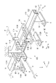
- FIG. 1 is a perspective view showing an example of the suspending tool 100 of the first embodiment.
- FIG. 2 is an exploded perspective view showing an example of the hanging tool 100.
- FIG. 3 is a plan view showing an example of the hanging tool 100.
- FIG. 4 is a side view showing an example of the suspending tool 100 seen from the first direction D1.
- the X direction as the first direction D1 and the Y direction as the second direction D2 are directions orthogonal to each other.
- the Z direction is a direction perpendicular to the XY plane.
- the X, Y, and Z directions form a so-called right-handed system.
- "upper” and “upper” mean the + Z direction.
- "downward” and “downward” mean the ⁇ Z direction.
- the X direction is an example of a "predetermined direction”.
- the Y direction is an example of "a direction intersecting a predetermined direction”.
- the hanging tool 100 is a member for suspending the suspended object Q through a grid-like groove V provided in the ceiling C provided in the building B.
- Building B includes, for example, a building of a semiconductor factory.
- the ceiling C is suspended from the ceiling of the building B by a hanging metal fitting H, for example.
- the ceiling C includes, for example, a plurality of rectangular frame members F arranged in a matrix, and a connecting member J for connecting the frame members F to each other.
- the connecting member J is connected to the hanging metal fitting H, and is arranged at each of the corners of the four frame members F among the plurality of frame members F.
- the connecting member J connects the corner portions of the four frame members F to each other.
- the connecting member J has a cross shape in a plan view.
- a grid-like groove V is formed between the plurality of frame members F.
- the first direction D1 is parallel to the groove V extending in the X direction among the grid-like grooves V.
- the second direction D2 is parallel to the groove V extending in the Y direction among the grid-like grooves V.
- the hanging tool 100 includes a fixing portion 110 and a main body portion 120.
- the fixing portion 110 is a member fixed to a plurality of points in the groove V.
- the fixing portion 110 includes a first suspension portion 111A, a second suspension portion 111B, a third suspension portion 111C, and a plate-shaped body 112.
- the first suspension portion 111A, the second suspension portion 111B, and the third suspension portion 111C are fixed to the groove V.
- the first suspension portion 111A is fixed to the first position P1 in the groove V.
- the second suspension portion 111B is fixed to the second position P2 in the groove V.
- the second position P2 is a position different from the first position P1.
- the third suspension portion 111C is fixed to the third position P3 in the groove V.
- the third position P3 is a position different from the first position P1 and the second position P2.
- the first suspension portion 111A, the second suspension portion 111B, and the third suspension portion 111C are arranged in a state where the height positions of the lower ends thereof are aligned.
- the plate-shaped body 112 is a member attached to the lower ends of the plurality of suspension portions 11 and spreads in the horizontal direction.
- the plate-shaped body 112 includes a first portion 112A, a second portion 112B, and a third portion 112C.
- the first portion 112A is fixed to the lower part of the first suspension portion 111A and extends in the first direction D1.
- the second portion 112B is fixed to the lower part of the second suspension portion 111B and extends in the first direction D1.
- the third portion 112C is fixed to the lower part of the third suspension portion 111C and extends in the second direction D2.
- the third portion 112C is connected to the first portion 112A and the second portion 112B, respectively.
- the first portion 112A, the second portion 112B, and the third portion 112C are arranged so as to have a U-shape or a U-shape in a plan view.
- the first guide portion G1 is provided in each of the first portion 112A and the second portion 112B.
- the first guide portion G1 connects the fixed portion 110 and the main body portion 120.
- the first guide portion G1 is an opening that penetrates the plate-shaped body 112 in the vertical direction.
- the first guide portion G1 extends in the first direction D1, for example. Within the length range of the first guide portion G1, the connection position of the main body portion 120 with respect to the fixed portion 110 can be changed.
- the main body portion 120 is a member connected to the fixed portion 110 and suspends the suspended object Q.
- the main body 120 includes a first raceway 121, a second raceway 122, and a straight member 123.
- the first raceway 121 is connected to the first guide portion G1 of the first portion 112A.
- the first raceway 121 extends in the second direction D2.
- the second raceway 122 is separated from the first raceway 121 and connected to the first guide portion G1 of the second portion 112B.
- the second raceway 122 extends in the second direction D2.
- the first raceway 121 and the second raceway 122 are arranged side by side in the second direction D2.
- the straight member 123 is, for example, plate-shaped and extends in the second direction D2.
- the straight member 123 is connected to the lower end of the first raceway 121 and the lower end of the second raceway 122 by a connecting member such as a bolt.
- the linear member 123 has an L-shape with the end portion of the first direction D1 bent downward. With this configuration, rigidity against a load in the vertical direction is ensured.
- the first raceway 121, the second raceway 122, and the straight member 123 each include a second guide portion G2.
- the second guide portion G2 is an opening that penetrates the bottoms of the first raceway 121 and the second raceway 122, and the straight member 123 in the vertical direction.
- the second guide portion G2 extends in the second direction D2.
- the hanging metal fitting Q1 of the suspended object Q is inserted into the second guide portion G2 in the vertical direction.
- a hanger Q2 is fixed to the lower end of the hanging metal fitting Q1 via a fixing member such as a nut.
- the second guide portion G2 can change the position of the hanging metal fitting Q1 in the second direction D2.
- the connection position of the suspended object Q with respect to the main body 120 in the second direction D2 can be changed.
- the second guide portion G2 of the straight line member 123 is arranged so as to straddle between the first raceway 121 and the second raceway 122 in the second direction D2. Therefore, the suspended object Q can be suspended below between the first raceway 121 and the second raceway 122 via the straight member 123.
- the straight member 123 is not directly connected to the plate-shaped body 112 but is connected via the first raceway 121 and the second raceway 122, the distance between the straight member 123 and the ceiling C is large. Largely secured. Therefore, even when equipment such as a fire alarm and a sprinkler is arranged in the groove V of the ceiling C, the suspended object Q can be suspended by bypassing the equipment.
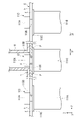
- FIG. 5 is an enlarged view showing the cross section of the ceiling C.
- the fixture 113 includes an upper flange 113A, a lower flange 113B and a connecting member 113C.
- the upper flange 113A is arranged so as to straddle between the upper surfaces of the adjacent frame members F.
- the lower flange 113B is arranged so as to straddle between the lower surfaces of the adjacent frame members F.
- the connecting member 113C connects the upper flange 113A and the lower flange 113B.
- the upper flange 113A is, for example, a plate-shaped member having a rectangular shape in a plan view, and a member having a length in the lateral direction shorter than the width of the groove V.
- the upper flange 113A may be, for example, a member in which two plate-shaped members having a rectangular shape in a plan view are joined to a hinge, and the two plate-shaped members can be opened and closed by an operation member (not shown).
- the operator arranges the fixture 113 at a desired position below the groove V with the two plate-shaped members joined to the hinge closed. Then, the operator inserts the upper flange 113A of the fixing tool 113 into the groove V and operates the operating member to open the two plate-shaped members, thereby fixing the fixing tool 113 at a desired position in the groove V. Can be done.
- FIG. 6 is a side view showing an example of the hanging tool 100 as seen from the second direction D2.
- FIG. 7 is a plan view showing the configuration in FIG.
- the suspended object Q is supported by a hanging metal fitting Q1 suspended from the first raceway 121 and the second raceway 122 via the hanging tool 100, and a hanging metal fitting Q1 suspended from another raceway 124.
- the suspending tool 100 can change the position of the suspended object Q with respect to the fixed portion 110 to the first direction D1 within the range of the length of the first guide portion G1, the distance between the adjacent grooves V and the suspension are suspended.
- the suspended object Q can be suspended even if the dimensions of the suspended object Q do not match, and the degree of freedom in the suspended position can be increased.
- the suspending tool 100 of the first embodiment includes the first guide portion G1
- the position of the suspended object Q with respect to the fixed portion 110 is set within the range of the length of the first guide portion G1. It can be changed to the direction D1.
- the suspending tool 100 of the first embodiment includes the second guide portion G2
- the position of the suspended object Q with respect to the fixed portion 110 is set within the range of the length of the second guide portion G2. It can be changed to the second direction D2. Therefore, the degree of freedom in the hanging position of the suspended object Q from the ceiling C can be increased.
- FIG. 8 is a perspective view showing an example of the hanging tool 200 of the second embodiment.
- FIG. 9 is a side view showing an example of the hanging tool 200.
- the hanging tool 200 includes a fixing portion 110 and a main body portion 220.
- the configuration of the fixed portion 110 is the same as the configuration of the fixed portion 110 in the first embodiment.
- the fixing portion 110 is arranged so as to bypass the equipment S such as a fire alarm and a sprinkler arranged in the groove V of the ceiling C.
- the main body 220 is not provided with the first raceway 121 and the second raceway 122.
- the main body portion 220 is a member that is connected to the fixed portion 110 and suspends the suspended object Q.
- the main body 220 is, for example, plate-shaped and extends in the second direction D2.
- the main body portion 220 is connected to the first guide portion G1 of the first portion 112A and the first guide portion G1 of the second portion 112B of the fixing portion 110 by a connecting member such as a bolt.
- the main body portion 220 includes a second guide portion G2.
- the second guide portion G2 is an opening that penetrates the main body portion 220 in the vertical direction.
- the second guide portion G2 extends in the second direction D2.
- the hanging metal fitting Q1 of the suspended object Q is inserted into the second guide portion G2 in the vertical direction.
- a hanger Q2 is fixed to the lower end of the hanging metal fitting Q1 via a fixing member such as a nut.
- the second guide portion G2 can change the position of the hanging metal fitting Q1 in the second direction D2. By changing the position of the hanging metal fitting Q1 with respect to the second direction D2, the connection position of the suspended object Q with respect to the main body 220 in the second direction D2 can be changed.
- the suspending tool 200 of the second embodiment can change the position of the suspended object Q with respect to the fixing portion 110 to the first direction D1 within the range of the length of the first guide portion G1. Further, the suspending tool 200 of the second embodiment can change the position of the suspended object Q with respect to the fixing portion 110 to the second direction D2 within the range of the length of the second guide portion G2. Further, the suspended object Q can be suspended below the vacant portion between the first portion 112A and the second portion 112B in the plate-shaped body 112 of the fixing portion 110 via the main body portion 220. Therefore, for example, even when the equipment S is arranged on the ceiling C, the suspended object Q can be suspended below the equipment S.
- the lengths of the first suspension portion 111A, the second suspension portion 111B, and the third suspension portion 111C in the vertical direction are designed so that the main body portion 220 is arranged at a height that does not interfere with the equipment S. Therefore, the degree of freedom in the hanging position of the suspended object Q from the ceiling C can be increased.
- FIG. 10 is a perspective view showing an example of the suspending tool 300 of the third embodiment.
- the hanging tool 300 includes a fixing portion 310 and a main body portion 320.
- the fixing portion 310 is a member fixed to a plurality of locations in the groove V.
- the fixing portion 310 includes a fourth suspension portion 311D, a fifth suspension portion 311E, and a plate-shaped body 312.
- the fourth suspension portion 311D is fixed to the fourth position P4 in the groove V.
- the fifth suspension portion 311E is fixed to the fifth position P5 in the groove V.
- the fifth position P5 is a position different from the fourth position P4.
- the fourth suspension portion 311D and the fifth suspension portion 311E are arranged in a state where the height positions of the lower ends thereof are aligned.
- the plate-shaped body 312 is fixed to the lower ends of the plurality of suspension portions 211.
- the plate-shaped body 312 includes a fourth portion 312D and a fifth portion 312E.
- the fourth portion 312D is fixed to the lower part of the fourth suspension portion 311D and extends in the first direction D1.
- the fifth portion 312E is fixed to the lower part of the fifth suspension portion 311E and extends in the second direction D2.
- the fifth portion 312E is connected to the fourth portion 312D.
- the fourth portion 312D and the fifth portion 312E are arranged so as to be L-shaped in a plan view.
- the first guide portion G1 is provided in the fourth portion 312D.
- the first guide portion G1 connects the fixed portion 310 and the main body portion 320.
- the first guide portion G1 is an opening that penetrates the plate-shaped body 312 in the vertical direction.
- the first guide portion G1 extends in the first direction D1, for example. Within the length range of the first guide portion G1, the connection position of the main body portion 320 with respect to the fixed portion 310 can be changed.
- the main body portion 320 is a member that is connected to the fixed portion 310 and suspends the suspended object Q.
- the main body 320 includes a third raceway 321.
- the third raceway 321 is connected to the first guide portion G1 of the fourth portion 312D.
- the third raceway 321 extends in the second direction D2.
- the third raceway 321 includes a second guide section G2.
- the second guide portion G2 is an opening that penetrates the bottom of the third raceway 321 in the vertical direction.
- the second guide portion G2 extends in the second direction D2.
- the hanging metal fitting Q1 of the suspended object Q is inserted into the second guide portion G2 in the vertical direction.
- a hanger Q2 is fixed to the lower end of the hanging metal fitting Q1 via a fixing member such as a nut.
- the second guide portion G2 can change the position of the hanging metal fitting Q1 in the second direction D2. By changing the position of the hanging metal fitting Q1 with respect to the second direction D2, the connection position of the suspended object Q with respect to the main body 320 in the second direction D2 can be changed.
- the suspending tool 300 of the third embodiment can change the position of the suspended object Q with respect to the fixing portion 310 to the first direction D1 within the range of the length of the first guide portion G1. Further, the suspending tool 300 of the third embodiment can change the position of the suspended object Q with respect to the fixing portion 310 to the second direction D2 within the range of the length of the second guide portion G2. Further, by guiding the third raceway 321 in the first direction D1 by the first guide portion G1, the degree of freedom in the position where the suspended object Q is suspended from the second guide portion G2 of the third raceway 321 is increased. Can be enhanced.
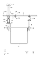
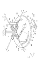
- FIG. 11 is a perspective view showing an example of the suspending tool 400 of the fourth embodiment.
- FIG. 12 is a plan view showing an example of the hanging tool 400.
- the hanging tool 400 includes a fixing portion 410 and a main body portion 420.
- the fixing portion 410 is a member fixed to a plurality of places in the groove V.
- the fixing portion 410 includes a sixth suspension portion 411F and a seventh suspension portion 411G.
- the sixth suspension portion 411F is fixed to the sixth position P6 in the groove V.
- the seventh suspension portion 411G is fixed to the seventh position P7 in the groove V.
- the seventh position P7 is a position different from the sixth position P6.
- the sixth suspension portion 411F and the seventh suspension portion 411G are arranged in a state where the height positions of the lower ends thereof are aligned.
- the main body portion 420 is a member that is connected to the fixed portion 410 and suspends the suspended object Q.
- the main body portion 420 is a plate-shaped member that is fixed to the lower ends of the plurality of suspension portions 311 and spreads in the horizontal direction.
- the main body 420 is circular, for example, in a plan view.
- the shape of the main body 420 in a plan view is not limited to a circle, and may be a polygonal shape such as a triangle or a rectangle, or an elliptical shape.
- the main body portion 420 includes a first arc guide portion G3, a second arc guide portion G4, and a second guide portion G2.
- the first arc guide portion G3 and the second arc guide portion G4 are examples of the "first guide portion".
- the first arc guide portion G3 and the second arc guide portion G4 have an arc shape centered on a common point O, and are arranged so as to face each other with the point O in the plan view.
- the point O may be arranged at the center of the main body portion 420, which has a circular shape in a plan view.
- the first arc guide portion G3 and the second arc guide portion G4 are provided in a range of 90 ° around the point O, for example, but the angle is not limited to this range, and the angle is smaller than 90 ° or larger than 90 °. It may be provided in the range of.
- the first arc guide portion G3 and the second arc guide portion G4 are openings that penetrate the main body portion 420 in the vertical direction. Within the length range of the first arc guide portion G3 and the second arc guide portion G4, the connection position of the main body portion 420 with respect to the fixed portion 410 can be changed.
- the second guide portion G2 is, for example, linear, and extends between the first arc guide portion G3 and the second arc guide portion G4.
- the second guide portion G2 is provided in the region including the point O.
- the second guide portion G2 is an opening that penetrates the main body portion 420 in the vertical direction.
- the hanging metal fitting Q1 of the suspended object Q is inserted into the second guide portion G2 in the vertical direction.
- a hanger Q2 is fixed to the lower end of the hanging metal fitting Q1 via a fixing member such as a nut.
- the second guide portion G2 can change the position of the hanging metal fitting Q1 in the second direction D2. By changing the position of the hanging metal fitting Q1 with respect to the second direction D2, the connection position of the suspended object Q with respect to the main body portion 420 in the second direction D2 can be changed.
- the plate-shaped main body 320 is rotated around a common point O, so that the suspended object Q suspended from the second guide portion G2 can be suspended at any position.
- the degree can be increased.
- Fixture 110 Fixture 111A 1st Suspension 111B 2nd Suspension 111C 3rd Suspension 112 Plate-like body 112A 1st part 112B 2nd part 112C 3rd part 113 Fixture 113A Upper flange 113B Lower flange 113C Connecting member 120 Main body 121 1st raceway 122 2nd raceway 123 Straight member 124 Raceway 200 Hanging tool 220 Main body part 300 Hanging tool 310 Fixed part 311D 4th hanging part 311E 5th hanging part 312 Plate-shaped body 312D 4th Part 312E 5th part 320 Main body part 321 3rd raceway 400 Hanging tool 410 Fixture 411F 6th hanging part 411G 7th hanging part 420 Main body part B Building C Ceiling D1 1st direction D2 2nd direction F Frame member G1 1st 1 Guide part G2 2nd guide part G3 1st arc guide part G4 2nd arc guide part H Hanging bracket P1 1st
Landscapes
- Engineering & Computer Science (AREA)
- General Engineering & Computer Science (AREA)
- Mechanical Engineering (AREA)
- Architecture (AREA)
- Physics & Mathematics (AREA)
- Electromagnetism (AREA)
- Civil Engineering (AREA)
- Structural Engineering (AREA)
- Supports For Pipes And Cables (AREA)
- Hooks, Suction Cups, And Attachment By Adhesive Means (AREA)
- Supports Or Holders For Household Use (AREA)
- Leg Units, Guards, And Driving Tracks Of Cranes (AREA)
- Holders For Apparel And Elements Relating To Apparel (AREA)
- Liquid Crystal (AREA)
- Eye Examination Apparatus (AREA)
- Devices For Conveying Motion By Means Of Endless Flexible Members (AREA)
Priority Applications (6)
| Application Number | Priority Date | Filing Date | Title |
|---|---|---|---|
| JP2022558903A JP7494936B2 (ja) | 2020-10-26 | 2021-09-14 | 吊り下げ具 |
| IL302290A IL302290B2 (en) | 2020-10-26 | 2021-09-14 | Hanging fixture |
| KR1020237013784A KR20230070508A (ko) | 2020-10-26 | 2021-09-14 | 현수구 |
| EP21885731.6A EP4234439A4 (en) | 2020-10-26 | 2021-09-14 | HANGING TOOL |
| US18/033,518 US12404675B2 (en) | 2020-10-26 | 2021-09-14 | Suspender |
| CN202180069779.0A CN116348395A (zh) | 2020-10-26 | 2021-09-14 | 悬挂工具 |
Applications Claiming Priority (2)
| Application Number | Priority Date | Filing Date | Title |
|---|---|---|---|
| JP2020-179085 | 2020-10-26 | ||
| JP2020179085 | 2020-10-26 |
Publications (1)
| Publication Number | Publication Date |
|---|---|
| WO2022091612A1 true WO2022091612A1 (ja) | 2022-05-05 |
Family
ID=81382331
Family Applications (1)
| Application Number | Title | Priority Date | Filing Date |
|---|---|---|---|
| PCT/JP2021/033703 Ceased WO2022091612A1 (ja) | 2020-10-26 | 2021-09-14 | 吊り下げ具 |
Country Status (8)
| Country | Link |
|---|---|
| US (1) | US12404675B2 (https=) |
| EP (1) | EP4234439A4 (https=) |
| JP (1) | JP7494936B2 (https=) |
| KR (1) | KR20230070508A (https=) |
| CN (1) | CN116348395A (https=) |
| IL (1) | IL302290B2 (https=) |
| TW (1) | TWI858290B (https=) |
| WO (1) | WO2022091612A1 (https=) |
Families Citing this family (1)
| Publication number | Priority date | Publication date | Assignee | Title |
|---|---|---|---|---|
| US12442489B2 (en) * | 2023-04-26 | 2025-10-14 | Hewlett Packard Enterprise Development Lp | Adjustable mounting bracket assembly for mounting an electronic device to a ceiling suspension system |
Citations (5)
| Publication number | Priority date | Publication date | Assignee | Title |
|---|---|---|---|---|
| JP2007126924A (ja) | 2005-11-07 | 2007-05-24 | Takenaka Komuten Co Ltd | クリーンルーム天井構造 |
| CN104326369A (zh) * | 2014-10-15 | 2015-02-04 | 中国一冶集团有限公司 | 步进式加热炉支撑梁更换装置及方法 |
| JP2020056464A (ja) * | 2018-10-02 | 2020-04-09 | エヌパット株式会社 | 支持装置及びそれを用いた施工方法 |
| WO2020153040A1 (ja) * | 2019-01-25 | 2020-07-30 | 村田機械株式会社 | 保管システム |
| JP2020179085A (ja) | 2019-04-24 | 2020-11-05 | 浦江県経玖水晶有限公司 | 水晶貯蔵箱 |
Family Cites Families (12)
| Publication number | Priority date | Publication date | Assignee | Title |
|---|---|---|---|---|
| US2650056A (en) * | 1950-05-16 | 1953-08-25 | William J Masoner | Support |
| US2963251A (en) * | 1958-02-07 | 1960-12-06 | William H Fuss | Channel hanger for supporting electric lighting fixtures from suspended ceiling framework |
| US3181274A (en) * | 1961-08-14 | 1965-05-04 | George C Izenour | Versatile display apparatus |
| US3459399A (en) * | 1967-01-16 | 1969-08-05 | Armstrong Cork Co | Beam mounted attaching device |
| US4109305A (en) * | 1976-04-23 | 1978-08-22 | Armstrong Cork Company | Relocatable suspended light fixture |
| JPH09279750A (ja) | 1996-04-15 | 1997-10-28 | Takusu:Kk | クリーンルームのパネル部材の吊り構造 |
| CN2430407Y (zh) * | 2000-06-02 | 2001-05-16 | 陈聪智 | 改良构造的垫片吸取装置 |
| CN1292709C (zh) * | 2002-01-22 | 2007-01-03 | 株式会社东芝 | 具有多个监视器的医学图象诊断设备 |
| JP4277287B2 (ja) * | 2006-11-27 | 2009-06-10 | 村田機械株式会社 | 天井走行車 |
| US7712239B2 (en) * | 2007-08-29 | 2010-05-11 | Rose Displays, Ltd. | Overhead adjustable track support arrangement |
| US20160363263A1 (en) * | 2015-02-11 | 2016-12-15 | Robert Stockham | System and method for movably mounting arena-type displays |
| US11186989B2 (en) * | 2015-10-07 | 2021-11-30 | Sld Technology, Inc. | Equipment support system and method of supporting equipment |
-
2021
- 2021-09-14 EP EP21885731.6A patent/EP4234439A4/en not_active Withdrawn
- 2021-09-14 KR KR1020237013784A patent/KR20230070508A/ko not_active Ceased
- 2021-09-14 WO PCT/JP2021/033703 patent/WO2022091612A1/ja not_active Ceased
- 2021-09-14 IL IL302290A patent/IL302290B2/en unknown
- 2021-09-14 JP JP2022558903A patent/JP7494936B2/ja active Active
- 2021-09-14 CN CN202180069779.0A patent/CN116348395A/zh active Pending
- 2021-09-14 US US18/033,518 patent/US12404675B2/en active Active
- 2021-10-25 TW TW110139443A patent/TWI858290B/zh active
Patent Citations (5)
| Publication number | Priority date | Publication date | Assignee | Title |
|---|---|---|---|---|
| JP2007126924A (ja) | 2005-11-07 | 2007-05-24 | Takenaka Komuten Co Ltd | クリーンルーム天井構造 |
| CN104326369A (zh) * | 2014-10-15 | 2015-02-04 | 中国一冶集团有限公司 | 步进式加热炉支撑梁更换装置及方法 |
| JP2020056464A (ja) * | 2018-10-02 | 2020-04-09 | エヌパット株式会社 | 支持装置及びそれを用いた施工方法 |
| WO2020153040A1 (ja) * | 2019-01-25 | 2020-07-30 | 村田機械株式会社 | 保管システム |
| JP2020179085A (ja) | 2019-04-24 | 2020-11-05 | 浦江県経玖水晶有限公司 | 水晶貯蔵箱 |
Non-Patent Citations (1)
| Title |
|---|
| See also references of EP4234439A4 |
Also Published As
| Publication number | Publication date |
|---|---|
| TW202231554A (zh) | 2022-08-16 |
| KR20230070508A (ko) | 2023-05-23 |
| CN116348395A (zh) | 2023-06-27 |
| TWI858290B (zh) | 2024-10-11 |
| US12404675B2 (en) | 2025-09-02 |
| US20230392374A1 (en) | 2023-12-07 |
| IL302290A (en) | 2023-06-01 |
| IL302290B1 (en) | 2025-10-01 |
| JP7494936B2 (ja) | 2024-06-04 |
| EP4234439A4 (en) | 2024-10-30 |
| IL302290B2 (en) | 2026-02-01 |
| EP4234439A1 (en) | 2023-08-30 |
| JPWO2022091612A1 (https=) | 2022-05-05 |
Similar Documents
| Publication | Publication Date | Title |
|---|---|---|
| US6061884A (en) | Interlocking cable support tray system | |
| EP3426946B1 (en) | Bracket and bracket system for seismic cable sway bracing system and method of forming a bracket | |
| JP5794868B2 (ja) | 天井下地構造 | |
| WO2022091612A1 (ja) | 吊り下げ具 | |
| US20200149275A1 (en) | Suspended ceiling pass through grid connector | |
| JP2015017390A (ja) | 天井用クリップ及び天井下地構造並びに天井下地構造の施工方法 | |
| JP6489613B2 (ja) | 吊天井の落下防止構造 | |
| KR102663214B1 (ko) | 천장패널의 연결구조 | |
| JP6205513B1 (ja) | 球面すべり支承の施工方法、固定治具付き球面すべり支承、および固定治具 | |
| JP5983809B2 (ja) | 垂直多関節型ロボット及びロボットセル | |
| JP7257668B2 (ja) | 振れ止め装置及び施工方法 | |
| JPWO2022091612A5 (https=) | ||
| JP3236028U (ja) | 吊り足場用吊り下げ具 | |
| JP2021017712A (ja) | 間仕切り構造 | |
| JP6763513B2 (ja) | 吊構造 | |
| JP2017129004A (ja) | 天井下地構造及び天井下地構造の施工方法 | |
| JP7257669B2 (ja) | 支持装置 | |
| JP2016169575A (ja) | 吊り足場の端部に用いられる端部用部材およびそれを備えた吊り足場 | |
| KR20240078698A (ko) | 고정클립장치를 이용한 벽체 마감시스템 | |
| JP2023168802A (ja) | 吊下げ架台 | |
| JP5820776B2 (ja) | 間仕切壁補強構造 | |
| JP2025006087A (ja) | 支持金具、及び支持金具の製造方法 | |
| JP2022117001A (ja) | 固定補強部材及び天井構造 | |
| JP6270502B2 (ja) | 耐火障壁 | |
| JPH0644848U (ja) | デッキプレート用天井吊り金具 |
Legal Events
| Date | Code | Title | Description |
|---|---|---|---|
| 121 | Ep: the epo has been informed by wipo that ep was designated in this application |
Ref document number: 21885731 Country of ref document: EP Kind code of ref document: A1 |
|
| ENP | Entry into the national phase |
Ref document number: 2022558903 Country of ref document: JP Kind code of ref document: A |
|
| ENP | Entry into the national phase |
Ref document number: 20237013784 Country of ref document: KR Kind code of ref document: A |
|
| NENP | Non-entry into the national phase |
Ref country code: DE |
|
| ENP | Entry into the national phase |
Ref document number: 2021885731 Country of ref document: EP Effective date: 20230526 |
|
| WWR | Wipo information: refused in national office |
Ref document number: 1020237013784 Country of ref document: KR |
|
| WWW | Wipo information: withdrawn in national office |
Ref document number: 2021885731 Country of ref document: EP |
|
| WWG | Wipo information: grant in national office |
Ref document number: 18033518 Country of ref document: US |
|
| WWG | Wipo information: grant in national office |
Ref document number: 302290 Country of ref document: IL |