WO2022091612A1 - Hanging tool - Google Patents
Hanging tool Download PDFInfo
- Publication number
- WO2022091612A1 WO2022091612A1 PCT/JP2021/033703 JP2021033703W WO2022091612A1 WO 2022091612 A1 WO2022091612 A1 WO 2022091612A1 JP 2021033703 W JP2021033703 W JP 2021033703W WO 2022091612 A1 WO2022091612 A1 WO 2022091612A1
- Authority
- WO
- WIPO (PCT)
- Prior art keywords
- guide portion
- fixed
- suspension
- main body
- groove
- Prior art date
Links
- 239000000725 suspension Substances 0.000 claims description 72
- 239000002184 metal Substances 0.000 description 20
- 239000011159 matrix material Substances 0.000 description 2
- 239000004065 semiconductor Substances 0.000 description 1
Images


Classifications
-
- E—FIXED CONSTRUCTIONS
- E04—BUILDING
- E04B—GENERAL BUILDING CONSTRUCTIONS; WALLS, e.g. PARTITIONS; ROOFS; FLOORS; CEILINGS; INSULATION OR OTHER PROTECTION OF BUILDINGS
- E04B9/00—Ceilings; Construction of ceilings, e.g. false ceilings; Ceiling construction with regard to insulation
- E04B9/006—Ceilings; Construction of ceilings, e.g. false ceilings; Ceiling construction with regard to insulation with means for hanging lighting fixtures or other appliances to the framework of the ceiling
-
- F—MECHANICAL ENGINEERING; LIGHTING; HEATING; WEAPONS; BLASTING
- F16—ENGINEERING ELEMENTS AND UNITS; GENERAL MEASURES FOR PRODUCING AND MAINTAINING EFFECTIVE FUNCTIONING OF MACHINES OR INSTALLATIONS; THERMAL INSULATION IN GENERAL
- F16M—FRAMES, CASINGS OR BEDS OF ENGINES, MACHINES OR APPARATUS, NOT SPECIFIC TO ENGINES, MACHINES OR APPARATUS PROVIDED FOR ELSEWHERE; STANDS; SUPPORTS
- F16M13/00—Other supports for positioning apparatus or articles; Means for steadying hand-held apparatus or articles
- F16M13/02—Other supports for positioning apparatus or articles; Means for steadying hand-held apparatus or articles for supporting on, or attaching to, an object, e.g. tree, gate, window-frame, cycle
- F16M13/027—Ceiling supports
-
- B—PERFORMING OPERATIONS; TRANSPORTING
- B65—CONVEYING; PACKING; STORING; HANDLING THIN OR FILAMENTARY MATERIAL
- B65G—TRANSPORT OR STORAGE DEVICES, e.g. CONVEYORS FOR LOADING OR TIPPING, SHOP CONVEYOR SYSTEMS OR PNEUMATIC TUBE CONVEYORS
- B65G1/00—Storing articles, individually or in orderly arrangement, in warehouses or magazines
- B65G1/02—Storage devices
- B65G1/04—Storage devices mechanical
-
- B—PERFORMING OPERATIONS; TRANSPORTING
- B66—HOISTING; LIFTING; HAULING
- B66C—CRANES; LOAD-ENGAGING ELEMENTS OR DEVICES FOR CRANES, CAPSTANS, WINCHES, OR TACKLES
- B66C6/00—Girders, or track-supporting structures, specially adapted for cranes
-
- F—MECHANICAL ENGINEERING; LIGHTING; HEATING; WEAPONS; BLASTING
- F16—ENGINEERING ELEMENTS AND UNITS; GENERAL MEASURES FOR PRODUCING AND MAINTAINING EFFECTIVE FUNCTIONING OF MACHINES OR INSTALLATIONS; THERMAL INSULATION IN GENERAL
- F16M—FRAMES, CASINGS OR BEDS OF ENGINES, MACHINES OR APPARATUS, NOT SPECIFIC TO ENGINES, MACHINES OR APPARATUS PROVIDED FOR ELSEWHERE; STANDS; SUPPORTS
- F16M11/00—Stands or trestles as supports for apparatus or articles placed thereon Stands for scientific apparatus such as gravitational force meters
- F16M11/02—Heads
- F16M11/04—Means for attachment of apparatus; Means allowing adjustment of the apparatus relatively to the stand
- F16M11/043—Allowing translations
-
- F—MECHANICAL ENGINEERING; LIGHTING; HEATING; WEAPONS; BLASTING
- F16—ENGINEERING ELEMENTS AND UNITS; GENERAL MEASURES FOR PRODUCING AND MAINTAINING EFFECTIVE FUNCTIONING OF MACHINES OR INSTALLATIONS; THERMAL INSULATION IN GENERAL
- F16M—FRAMES, CASINGS OR BEDS OF ENGINES, MACHINES OR APPARATUS, NOT SPECIFIC TO ENGINES, MACHINES OR APPARATUS PROVIDED FOR ELSEWHERE; STANDS; SUPPORTS
- F16M11/00—Stands or trestles as supports for apparatus or articles placed thereon Stands for scientific apparatus such as gravitational force meters
- F16M11/20—Undercarriages with or without wheels
- F16M11/2085—Undercarriages with or without wheels comprising means allowing sideward adjustment, i.e. left-right translation of the head relatively to the undercarriage
-
- F—MECHANICAL ENGINEERING; LIGHTING; HEATING; WEAPONS; BLASTING
- F16—ENGINEERING ELEMENTS AND UNITS; GENERAL MEASURES FOR PRODUCING AND MAINTAINING EFFECTIVE FUNCTIONING OF MACHINES OR INSTALLATIONS; THERMAL INSULATION IN GENERAL
- F16M—FRAMES, CASINGS OR BEDS OF ENGINES, MACHINES OR APPARATUS, NOT SPECIFIC TO ENGINES, MACHINES OR APPARATUS PROVIDED FOR ELSEWHERE; STANDS; SUPPORTS
- F16M13/00—Other supports for positioning apparatus or articles; Means for steadying hand-held apparatus or articles
- F16M13/02—Other supports for positioning apparatus or articles; Means for steadying hand-held apparatus or articles for supporting on, or attaching to, an object, e.g. tree, gate, window-frame, cycle
Definitions
- the present invention relates to a hanging tool.
- the ceiling is suspended from the building (see, for example, Patent Document 1).
- a plurality of rectangular frame members are arranged in a matrix, and a grid-like groove is formed between the plurality of frame members.
- a hanging tool is attached through this groove, and the suspended object is held through the hanging tool.
- the groove may not be formed at the intersection.
- equipment such as sprinklers may already be suspended in a part of the groove of the frame.
- the hanging tool cannot be attached near the intersection of the grooves and the vicinity of the equipment, there is a problem that it is not easy to hang the suspended object, for example, a special hanging tool is required. ..
- An object of the present invention is to provide a hanging tool capable of increasing the degree of freedom in the hanging position of a suspended object suspended from the ceiling.
- the hanging tool in the aspect of the present invention is a hanging tool for suspending a suspended object through a grid-like groove provided in the ceiling provided in the building, and is fixed to a plurality of places in the groove.
- a fixed portion and a main body portion connected to the fixed portion and suspending a suspended object are provided, and one of the fixed portion and the main body portion is used to connect the fixed portion and the main body portion.
- a first guide portion extending in one direction is provided, and the connection position of the main body portion with respect to the fixed portion can be changed within the length of the first guide portion, and a suspended object is suspended from the main body portion. Therefore, a second guide portion extending in a second direction different from the first direction is provided, and the hanging position of the suspended object with respect to the main body portion can be changed within the range of the length of the second guide portion.
- the suspending tool of the above aspect can change the position of the suspended object in the first direction and the second direction within the range of the length of the first guide portion and the range of the length of the second guide portion, and can be covered. It is possible to increase the degree of freedom in the position where the suspended object is suspended.
- the first direction is parallel to the groove extending in a predetermined direction among the grid-like grooves
- the second direction is parallel to the groove extending in a direction intersecting the predetermined direction among the grid-like grooves.
- the fixing portion may include a plurality of suspension portions fixed to the groove and a plate-shaped body attached to the lower ends of the plurality of suspension portions and spreading in the horizontal direction.
- the hanging portion and the plate-shaped body can be formed into an appropriate shape according to the use such as a hanging load, the suspended object can be stably suspended.
- the plurality of suspension portions are the first suspension portion fixed to the first position in the groove, the second suspension portion fixed to the second position different from the first position in the groove, and the first position and the second position in the groove.
- the plate-like body is fixed to the lower part of the first hanging part, and is fixed to the lower part of the first hanging part and extends in the first direction, and the lower part of the second hanging part. It comprises a second portion that is fixed and extends in the first direction, and a third portion that is fixed to the lower part of the third suspension portion and extends in the second direction and is connected to the first portion and the second portion, respectively.
- a first guide portion may be provided in each of the first portion and the second portion. Since the hanging tool of this embodiment holds the plate-shaped body by a plurality of hanging portions, the plate-shaped body can be reliably held. Further, the vacant portion between the first portion and the second portion can avoid interference with the equipment when the equipment is already set in the groove.
- the main body is connected to the first guide portion of the first portion, is connected to the first guide portion of the second portion separated from the first raceway extending in the second direction and the first raceway, and is connected to the second guide portion.
- a second raceway extending in the direction is provided, and the first raceway and the second raceway may each include a second guide portion.
- the main body portion is connected to the lower end of the first raceway and the lower end of the second raceway, and includes a straight member extending in the second direction, and the straight member may be provided with a second guide portion.
- the suspending tool of this aspect can suspend the suspended object via a linear member below between the first raceway and the second raceway.
- the main body portion is a member that is connected to the first guide portion of the first portion and the first guide portion of the second portion and extends in the second direction, and the main body portion may be provided with the second guide portion. ..
- the suspended object can be suspended via the main body portion below the empty portion between the first portion and the second portion of the plate-shaped body.
- the plurality of suspension portions include a fourth suspension portion fixed at a fourth position in the groove and a fifth suspension portion fixed at a fifth position different from the fourth position in the groove, and the plate-shaped body is a first.
- a fourth portion fixed to the lower end of the hanging portion and extending in the first direction, and a fifth portion fixed to the lower end of the fifth hanging portion and extending in the second direction and connected to the fourth portion are provided.
- the fourth portion is provided with a first guide portion
- the main body portion is connected to the first guide portion of the fourth portion, and is provided with a third raceway extending in a second direction
- the third raceway is a second raceway.
- a guide section may be provided.
- the third raceway is guided in the first direction by the first guide portion, so that the suspended object is suspended from the second guide portion of the third raceway. The degree of freedom can be increased.
- the fixing portion includes a sixth suspension portion fixed at the sixth position in the groove and a seventh suspension portion fixed at a seventh position different from the sixth position in the groove, and the main body portion is a sixth suspension portion. It is a plate-shaped member attached to the lower part of the 7th hanging portion and spreads horizontally, and is attached to the arcuate first arc-shaped guide portion as the 1st guide portion corresponding to the 6th hanging portion and the 7th hanging portion.
- a circular second arc guide portion and a linear second guide portion are provided as the corresponding first guide portions, and the first arc guide portion and the second arc guide portion are centered on a common point.
- the second guide portion may be provided so as to extend between the first arc guide portion and the second arc guide portion in a plan view. In the hanging tool of this aspect, the degree of freedom of the hanging position of the suspended object suspended from the second guide portion can be increased by rotating the main body portion around a common point.
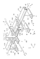
- FIG. 1 is a perspective view showing an example of the suspending tool 100 of the first embodiment.
- FIG. 2 is an exploded perspective view showing an example of the hanging tool 100.
- FIG. 3 is a plan view showing an example of the hanging tool 100.
- FIG. 4 is a side view showing an example of the suspending tool 100 seen from the first direction D1.
- the X direction as the first direction D1 and the Y direction as the second direction D2 are directions orthogonal to each other.
- the Z direction is a direction perpendicular to the XY plane.
- the X, Y, and Z directions form a so-called right-handed system.
- "upper” and “upper” mean the + Z direction.
- "downward” and “downward” mean the ⁇ Z direction.
- the X direction is an example of a "predetermined direction”.
- the Y direction is an example of "a direction intersecting a predetermined direction”.
- the hanging tool 100 is a member for suspending the suspended object Q through a grid-like groove V provided in the ceiling C provided in the building B.
- Building B includes, for example, a building of a semiconductor factory.
- the ceiling C is suspended from the ceiling of the building B by a hanging metal fitting H, for example.
- the ceiling C includes, for example, a plurality of rectangular frame members F arranged in a matrix, and a connecting member J for connecting the frame members F to each other.
- the connecting member J is connected to the hanging metal fitting H, and is arranged at each of the corners of the four frame members F among the plurality of frame members F.
- the connecting member J connects the corner portions of the four frame members F to each other.
- the connecting member J has a cross shape in a plan view.
- a grid-like groove V is formed between the plurality of frame members F.
- the first direction D1 is parallel to the groove V extending in the X direction among the grid-like grooves V.
- the second direction D2 is parallel to the groove V extending in the Y direction among the grid-like grooves V.
- the hanging tool 100 includes a fixing portion 110 and a main body portion 120.
- the fixing portion 110 is a member fixed to a plurality of points in the groove V.
- the fixing portion 110 includes a first suspension portion 111A, a second suspension portion 111B, a third suspension portion 111C, and a plate-shaped body 112.
- the first suspension portion 111A, the second suspension portion 111B, and the third suspension portion 111C are fixed to the groove V.
- the first suspension portion 111A is fixed to the first position P1 in the groove V.
- the second suspension portion 111B is fixed to the second position P2 in the groove V.
- the second position P2 is a position different from the first position P1.
- the third suspension portion 111C is fixed to the third position P3 in the groove V.
- the third position P3 is a position different from the first position P1 and the second position P2.
- the first suspension portion 111A, the second suspension portion 111B, and the third suspension portion 111C are arranged in a state where the height positions of the lower ends thereof are aligned.
- the plate-shaped body 112 is a member attached to the lower ends of the plurality of suspension portions 11 and spreads in the horizontal direction.
- the plate-shaped body 112 includes a first portion 112A, a second portion 112B, and a third portion 112C.
- the first portion 112A is fixed to the lower part of the first suspension portion 111A and extends in the first direction D1.
- the second portion 112B is fixed to the lower part of the second suspension portion 111B and extends in the first direction D1.
- the third portion 112C is fixed to the lower part of the third suspension portion 111C and extends in the second direction D2.
- the third portion 112C is connected to the first portion 112A and the second portion 112B, respectively.
- the first portion 112A, the second portion 112B, and the third portion 112C are arranged so as to have a U-shape or a U-shape in a plan view.
- the first guide portion G1 is provided in each of the first portion 112A and the second portion 112B.
- the first guide portion G1 connects the fixed portion 110 and the main body portion 120.
- the first guide portion G1 is an opening that penetrates the plate-shaped body 112 in the vertical direction.
- the first guide portion G1 extends in the first direction D1, for example. Within the length range of the first guide portion G1, the connection position of the main body portion 120 with respect to the fixed portion 110 can be changed.
- the main body portion 120 is a member connected to the fixed portion 110 and suspends the suspended object Q.
- the main body 120 includes a first raceway 121, a second raceway 122, and a straight member 123.
- the first raceway 121 is connected to the first guide portion G1 of the first portion 112A.
- the first raceway 121 extends in the second direction D2.
- the second raceway 122 is separated from the first raceway 121 and connected to the first guide portion G1 of the second portion 112B.
- the second raceway 122 extends in the second direction D2.
- the first raceway 121 and the second raceway 122 are arranged side by side in the second direction D2.
- the straight member 123 is, for example, plate-shaped and extends in the second direction D2.
- the straight member 123 is connected to the lower end of the first raceway 121 and the lower end of the second raceway 122 by a connecting member such as a bolt.
- the linear member 123 has an L-shape with the end portion of the first direction D1 bent downward. With this configuration, rigidity against a load in the vertical direction is ensured.
- the first raceway 121, the second raceway 122, and the straight member 123 each include a second guide portion G2.
- the second guide portion G2 is an opening that penetrates the bottoms of the first raceway 121 and the second raceway 122, and the straight member 123 in the vertical direction.
- the second guide portion G2 extends in the second direction D2.
- the hanging metal fitting Q1 of the suspended object Q is inserted into the second guide portion G2 in the vertical direction.
- a hanger Q2 is fixed to the lower end of the hanging metal fitting Q1 via a fixing member such as a nut.
- the second guide portion G2 can change the position of the hanging metal fitting Q1 in the second direction D2.
- the connection position of the suspended object Q with respect to the main body 120 in the second direction D2 can be changed.
- the second guide portion G2 of the straight line member 123 is arranged so as to straddle between the first raceway 121 and the second raceway 122 in the second direction D2. Therefore, the suspended object Q can be suspended below between the first raceway 121 and the second raceway 122 via the straight member 123.
- the straight member 123 is not directly connected to the plate-shaped body 112 but is connected via the first raceway 121 and the second raceway 122, the distance between the straight member 123 and the ceiling C is large. Largely secured. Therefore, even when equipment such as a fire alarm and a sprinkler is arranged in the groove V of the ceiling C, the suspended object Q can be suspended by bypassing the equipment.
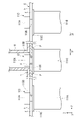
- FIG. 5 is an enlarged view showing the cross section of the ceiling C.
- the fixture 113 includes an upper flange 113A, a lower flange 113B and a connecting member 113C.
- the upper flange 113A is arranged so as to straddle between the upper surfaces of the adjacent frame members F.
- the lower flange 113B is arranged so as to straddle between the lower surfaces of the adjacent frame members F.
- the connecting member 113C connects the upper flange 113A and the lower flange 113B.
- the upper flange 113A is, for example, a plate-shaped member having a rectangular shape in a plan view, and a member having a length in the lateral direction shorter than the width of the groove V.
- the upper flange 113A may be, for example, a member in which two plate-shaped members having a rectangular shape in a plan view are joined to a hinge, and the two plate-shaped members can be opened and closed by an operation member (not shown).
- the operator arranges the fixture 113 at a desired position below the groove V with the two plate-shaped members joined to the hinge closed. Then, the operator inserts the upper flange 113A of the fixing tool 113 into the groove V and operates the operating member to open the two plate-shaped members, thereby fixing the fixing tool 113 at a desired position in the groove V. Can be done.
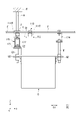
- FIG. 6 is a side view showing an example of the hanging tool 100 as seen from the second direction D2.
- FIG. 7 is a plan view showing the configuration in FIG.
- the suspended object Q is supported by a hanging metal fitting Q1 suspended from the first raceway 121 and the second raceway 122 via the hanging tool 100, and a hanging metal fitting Q1 suspended from another raceway 124.
- the suspending tool 100 can change the position of the suspended object Q with respect to the fixed portion 110 to the first direction D1 within the range of the length of the first guide portion G1, the distance between the adjacent grooves V and the suspension are suspended.
- the suspended object Q can be suspended even if the dimensions of the suspended object Q do not match, and the degree of freedom in the suspended position can be increased.
- the suspending tool 100 of the first embodiment includes the first guide portion G1
- the position of the suspended object Q with respect to the fixed portion 110 is set within the range of the length of the first guide portion G1. It can be changed to the direction D1.
- the suspending tool 100 of the first embodiment includes the second guide portion G2
- the position of the suspended object Q with respect to the fixed portion 110 is set within the range of the length of the second guide portion G2. It can be changed to the second direction D2. Therefore, the degree of freedom in the hanging position of the suspended object Q from the ceiling C can be increased.
- FIG. 8 is a perspective view showing an example of the hanging tool 200 of the second embodiment.
- FIG. 9 is a side view showing an example of the hanging tool 200.
- the hanging tool 200 includes a fixing portion 110 and a main body portion 220.
- the configuration of the fixed portion 110 is the same as the configuration of the fixed portion 110 in the first embodiment.
- the fixing portion 110 is arranged so as to bypass the equipment S such as a fire alarm and a sprinkler arranged in the groove V of the ceiling C.
- the main body 220 is not provided with the first raceway 121 and the second raceway 122.
- the main body portion 220 is a member that is connected to the fixed portion 110 and suspends the suspended object Q.
- the main body 220 is, for example, plate-shaped and extends in the second direction D2.
- the main body portion 220 is connected to the first guide portion G1 of the first portion 112A and the first guide portion G1 of the second portion 112B of the fixing portion 110 by a connecting member such as a bolt.
- the main body portion 220 includes a second guide portion G2.
- the second guide portion G2 is an opening that penetrates the main body portion 220 in the vertical direction.
- the second guide portion G2 extends in the second direction D2.
- the hanging metal fitting Q1 of the suspended object Q is inserted into the second guide portion G2 in the vertical direction.
- a hanger Q2 is fixed to the lower end of the hanging metal fitting Q1 via a fixing member such as a nut.
- the second guide portion G2 can change the position of the hanging metal fitting Q1 in the second direction D2. By changing the position of the hanging metal fitting Q1 with respect to the second direction D2, the connection position of the suspended object Q with respect to the main body 220 in the second direction D2 can be changed.
- the suspending tool 200 of the second embodiment can change the position of the suspended object Q with respect to the fixing portion 110 to the first direction D1 within the range of the length of the first guide portion G1. Further, the suspending tool 200 of the second embodiment can change the position of the suspended object Q with respect to the fixing portion 110 to the second direction D2 within the range of the length of the second guide portion G2. Further, the suspended object Q can be suspended below the vacant portion between the first portion 112A and the second portion 112B in the plate-shaped body 112 of the fixing portion 110 via the main body portion 220. Therefore, for example, even when the equipment S is arranged on the ceiling C, the suspended object Q can be suspended below the equipment S.
- the lengths of the first suspension portion 111A, the second suspension portion 111B, and the third suspension portion 111C in the vertical direction are designed so that the main body portion 220 is arranged at a height that does not interfere with the equipment S. Therefore, the degree of freedom in the hanging position of the suspended object Q from the ceiling C can be increased.
- FIG. 10 is a perspective view showing an example of the suspending tool 300 of the third embodiment.
- the hanging tool 300 includes a fixing portion 310 and a main body portion 320.
- the fixing portion 310 is a member fixed to a plurality of locations in the groove V.
- the fixing portion 310 includes a fourth suspension portion 311D, a fifth suspension portion 311E, and a plate-shaped body 312.
- the fourth suspension portion 311D is fixed to the fourth position P4 in the groove V.
- the fifth suspension portion 311E is fixed to the fifth position P5 in the groove V.
- the fifth position P5 is a position different from the fourth position P4.
- the fourth suspension portion 311D and the fifth suspension portion 311E are arranged in a state where the height positions of the lower ends thereof are aligned.
- the plate-shaped body 312 is fixed to the lower ends of the plurality of suspension portions 211.
- the plate-shaped body 312 includes a fourth portion 312D and a fifth portion 312E.
- the fourth portion 312D is fixed to the lower part of the fourth suspension portion 311D and extends in the first direction D1.
- the fifth portion 312E is fixed to the lower part of the fifth suspension portion 311E and extends in the second direction D2.
- the fifth portion 312E is connected to the fourth portion 312D.
- the fourth portion 312D and the fifth portion 312E are arranged so as to be L-shaped in a plan view.
- the first guide portion G1 is provided in the fourth portion 312D.
- the first guide portion G1 connects the fixed portion 310 and the main body portion 320.
- the first guide portion G1 is an opening that penetrates the plate-shaped body 312 in the vertical direction.
- the first guide portion G1 extends in the first direction D1, for example. Within the length range of the first guide portion G1, the connection position of the main body portion 320 with respect to the fixed portion 310 can be changed.
- the main body portion 320 is a member that is connected to the fixed portion 310 and suspends the suspended object Q.
- the main body 320 includes a third raceway 321.
- the third raceway 321 is connected to the first guide portion G1 of the fourth portion 312D.
- the third raceway 321 extends in the second direction D2.
- the third raceway 321 includes a second guide section G2.
- the second guide portion G2 is an opening that penetrates the bottom of the third raceway 321 in the vertical direction.
- the second guide portion G2 extends in the second direction D2.
- the hanging metal fitting Q1 of the suspended object Q is inserted into the second guide portion G2 in the vertical direction.
- a hanger Q2 is fixed to the lower end of the hanging metal fitting Q1 via a fixing member such as a nut.
- the second guide portion G2 can change the position of the hanging metal fitting Q1 in the second direction D2. By changing the position of the hanging metal fitting Q1 with respect to the second direction D2, the connection position of the suspended object Q with respect to the main body 320 in the second direction D2 can be changed.
- the suspending tool 300 of the third embodiment can change the position of the suspended object Q with respect to the fixing portion 310 to the first direction D1 within the range of the length of the first guide portion G1. Further, the suspending tool 300 of the third embodiment can change the position of the suspended object Q with respect to the fixing portion 310 to the second direction D2 within the range of the length of the second guide portion G2. Further, by guiding the third raceway 321 in the first direction D1 by the first guide portion G1, the degree of freedom in the position where the suspended object Q is suspended from the second guide portion G2 of the third raceway 321 is increased. Can be enhanced.
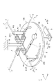
- FIG. 11 is a perspective view showing an example of the suspending tool 400 of the fourth embodiment.
- FIG. 12 is a plan view showing an example of the hanging tool 400.
- the hanging tool 400 includes a fixing portion 410 and a main body portion 420.
- the fixing portion 410 is a member fixed to a plurality of places in the groove V.
- the fixing portion 410 includes a sixth suspension portion 411F and a seventh suspension portion 411G.
- the sixth suspension portion 411F is fixed to the sixth position P6 in the groove V.
- the seventh suspension portion 411G is fixed to the seventh position P7 in the groove V.
- the seventh position P7 is a position different from the sixth position P6.
- the sixth suspension portion 411F and the seventh suspension portion 411G are arranged in a state where the height positions of the lower ends thereof are aligned.
- the main body portion 420 is a member that is connected to the fixed portion 410 and suspends the suspended object Q.
- the main body portion 420 is a plate-shaped member that is fixed to the lower ends of the plurality of suspension portions 311 and spreads in the horizontal direction.
- the main body 420 is circular, for example, in a plan view.
- the shape of the main body 420 in a plan view is not limited to a circle, and may be a polygonal shape such as a triangle or a rectangle, or an elliptical shape.
- the main body portion 420 includes a first arc guide portion G3, a second arc guide portion G4, and a second guide portion G2.
- the first arc guide portion G3 and the second arc guide portion G4 are examples of the "first guide portion".
- the first arc guide portion G3 and the second arc guide portion G4 have an arc shape centered on a common point O, and are arranged so as to face each other with the point O in the plan view.
- the point O may be arranged at the center of the main body portion 420, which has a circular shape in a plan view.
- the first arc guide portion G3 and the second arc guide portion G4 are provided in a range of 90 ° around the point O, for example, but the angle is not limited to this range, and the angle is smaller than 90 ° or larger than 90 °. It may be provided in the range of.
- the first arc guide portion G3 and the second arc guide portion G4 are openings that penetrate the main body portion 420 in the vertical direction. Within the length range of the first arc guide portion G3 and the second arc guide portion G4, the connection position of the main body portion 420 with respect to the fixed portion 410 can be changed.
- the second guide portion G2 is, for example, linear, and extends between the first arc guide portion G3 and the second arc guide portion G4.
- the second guide portion G2 is provided in the region including the point O.
- the second guide portion G2 is an opening that penetrates the main body portion 420 in the vertical direction.
- the hanging metal fitting Q1 of the suspended object Q is inserted into the second guide portion G2 in the vertical direction.
- a hanger Q2 is fixed to the lower end of the hanging metal fitting Q1 via a fixing member such as a nut.
- the second guide portion G2 can change the position of the hanging metal fitting Q1 in the second direction D2. By changing the position of the hanging metal fitting Q1 with respect to the second direction D2, the connection position of the suspended object Q with respect to the main body portion 420 in the second direction D2 can be changed.
- the plate-shaped main body 320 is rotated around a common point O, so that the suspended object Q suspended from the second guide portion G2 can be suspended at any position.
- the degree can be increased.
- Fixture 110 Fixture 111A 1st Suspension 111B 2nd Suspension 111C 3rd Suspension 112 Plate-like body 112A 1st part 112B 2nd part 112C 3rd part 113 Fixture 113A Upper flange 113B Lower flange 113C Connecting member 120 Main body 121 1st raceway 122 2nd raceway 123 Straight member 124 Raceway 200 Hanging tool 220 Main body part 300 Hanging tool 310 Fixed part 311D 4th hanging part 311E 5th hanging part 312 Plate-shaped body 312D 4th Part 312E 5th part 320 Main body part 321 3rd raceway 400 Hanging tool 410 Fixture 411F 6th hanging part 411G 7th hanging part 420 Main body part B Building C Ceiling D1 1st direction D2 2nd direction F Frame member G1 1st 1 Guide part G2 2nd guide part G3 1st arc guide part G4 2nd arc guide part H Hanging bracket P1 1st
Abstract
Description
110 固定部
111A 第1吊り部
111B 第2吊り部
111C 第3吊り部
112 板状体
112A 第1部分
112B 第2部分
112C 第3部分
113 固定具
113A 上フランジ
113B 下フランジ
113C 連結部材
120 本体部
121 第1レースウェイ
122 第2レースウェイ
123 直線部材
124 レースウェイ
200 吊り下げ具
220 本体部
300 吊り下げ具
310 固定部
311D 第4吊り部
311E 第5吊り部
312 板状体
312D 第4部分
312E 第5部分
320 本体部
321 第3レースウェイ
400 吊り下げ具
410 固定部
411F 第6吊り部
411G 第7吊り部
420 本体部
B 建屋
C 天井
D1 第1方向
D2 第2方向
F フレーム部材
G1 第1ガイド部
G2 第2ガイド部
G3 第1円弧ガイド部
G4 第2円弧ガイド部
H 吊り金具
P1 第1位置
P2 第2位置
P3 第3位置
P4 第4位置
P5 第5位置
P6 第6位置
P7 第7位置
Q 被吊り下げ物
Q1 吊り金具
Q2 ハンガ
S 設備
V 溝 100
Claims (9)
- 建屋に備える天井に設けられた格子状の溝を介して被吊り下げ物を吊り下げるための吊り下げ具であって、
前記溝における複数の箇所に固定される固定部と、
前記固定部に接続され、前記被吊り下げ物を吊り下げる本体部と、を備え、
前記固定部と前記本体部とのいずれか一方には、前記固定部と前記本体部とを接続するための、第1方向に延びる第1ガイド部が設けられ、
前記第1ガイド部の長さの範囲内において、前記固定部に対する前記本体部の接続位置を変更可能であり、
前記本体部には、前記被吊り下げ物を吊り下げるための、前記第1方向と異なる第2方向に延びる第2ガイド部が設けられ、
前記第2ガイド部の長さの範囲内において、前記本体部に対する前記被吊り下げ物の吊り下げ位置を変更可能である、吊り下げ具。 It is a hanging tool for hanging a suspended object through a grid-like groove provided in the ceiling provided in the building.
Fixing parts fixed at multiple points in the groove,
It is provided with a main body portion that is connected to the fixing portion and suspends the suspended object.
One of the fixed portion and the main body portion is provided with a first guide portion extending in the first direction for connecting the fixed portion and the main body portion.
Within the length of the first guide portion, the connection position of the main body portion with respect to the fixed portion can be changed.
The main body is provided with a second guide portion extending in a second direction different from the first direction for suspending the suspended object.
A hanging tool capable of changing the hanging position of the suspended object with respect to the main body within the range of the length of the second guide portion. - 前記第1方向は、前記格子状の溝のうちの所定の方向に延びる溝と平行であり、
前記第2方向は、前記格子状の溝のうちの前記所定の方向と交差する方向に延びる溝と平行である、請求項1に記載の吊り下げ具。 The first direction is parallel to the groove extending in a predetermined direction among the grid-like grooves.
The suspender according to claim 1, wherein the second direction is parallel to a groove extending in a direction intersecting the predetermined direction among the grid-like grooves. - 前記固定部は、前記溝に固定される複数の吊り部と、前記複数の吊り部の下端に取り付けられて水平方向に広がる板状体と、を備える、請求項1又は請求項2に記載の吊り下げ具。 The first or second aspect of the present invention, wherein the fixing portion includes a plurality of suspension portions fixed to the groove, and a plate-shaped body attached to the lower ends of the plurality of suspension portions and extending in the horizontal direction. Hanging tool.
- 前記複数の吊り部は、
前記溝における第1位置に固定される第1吊り部と、
前記溝における前記第1位置と異なる第2位置に固定される第2吊り部と、
前記溝における前記第1位置及び前記第2位置と異なる第3位置に固定される第3吊り部と、を備え、
前記板状体は、
前記第1吊り部の下部に固定され、前記第1方向に延びる第1部分と、
前記第2吊り部の下部に固定され、前記第1方向に延びる第2部分と、
前記第3吊り部の下部に固定され、前記第2方向に延びて前記第1部分及び前記第2部分にそれぞれ接続される第3部分と、を備え、
前記第1部分及び前記第2部分には、それぞれ前記第1ガイド部が設けられる、請求項3に記載の吊り下げ具。 The plurality of hanging portions are
The first suspension portion fixed to the first position in the groove,
A second suspension portion fixed to a second position different from the first position in the groove,
A third suspension portion fixed to the first position in the groove and a third position different from the second position is provided.
The plate-shaped body is
The first portion fixed to the lower part of the first suspension portion and extending in the first direction, and the first portion.
A second portion fixed to the lower part of the second suspension portion and extending in the first direction, and a second portion.
A third portion fixed to the lower portion of the third suspension portion, extending in the second direction and connected to the first portion and the second portion, respectively, is provided.
The hanging tool according to claim 3, wherein the first guide portion is provided in each of the first portion and the second portion. - 前記本体部は、
前記第1部分の前記第1ガイド部に接続され、前記第2方向に延びる第1レースウェイと、
前記第1レースウェイとは離間して前記第2部分の前記第1ガイド部に接続され、前記第2方向に延びる第2レースウェイと、を備え、
前記第1レースウェイ及び前記第2レースウェイは、それぞれ前記第2ガイド部を備える、請求項4に記載の吊り下げ具。 The main body is
A first raceway connected to the first guide portion of the first portion and extending in the second direction,
A second raceway, which is separated from the first raceway and is connected to the first guide portion of the second portion and extends in the second direction, is provided.
The hanging tool according to claim 4, wherein the first raceway and the second raceway each include the second guide portion. - 前記本体部は、前記第1レースウェイの下端と前記第2レースウェイの下端とに接続され、前記第2方向に延びる直線部材を備え、
前記直線部材には、前記第2ガイド部が設けられる、請求項5に記載の吊り下げ具。 The main body portion includes a linear member connected to the lower end of the first raceway and the lower end of the second raceway and extending in the second direction.
The suspending tool according to claim 5, wherein the straight member is provided with the second guide portion. - 前記本体部は、前記第1部分の前記第1ガイド部、及び前記第2部分の前記第1ガイド部にそれぞれ接続され、前記第2方向に延びる部材であり、
前記本体部には、前記第2ガイド部が設けられる、請求項4に記載の吊り下げ具。 The main body is a member that is connected to the first guide portion of the first portion and the first guide portion of the second portion and extends in the second direction.
The hanging tool according to claim 4, wherein the second guide portion is provided on the main body portion. - 前記複数の吊り部は、
前記溝における第4位置に固定される第4吊り部と、
前記溝における前記第4位置と異なる第5位置に固定される第5吊り部と、を備え、
前記板状体は、
前記第4吊り部の下端に固定され、前記第1方向に延びる第4部分と、
前記第5吊り部の下端に固定され、前記第2方向に延びて前記第4部分に接続される第5部分と、を備え、
前記第4部分には、前記第1ガイド部が設けられ、
前記本体部は、前記第4部分の前記第1ガイド部に接続され、前記第2方向に延びる第3レースウェイを備え、
前記第3レースウェイは、前記第2ガイド部を備える、請求項3に記載の吊り下げ具。 The plurality of hanging portions are
A fourth suspension portion fixed to a fourth position in the groove,
A fifth suspension portion fixed to a fifth position different from the fourth position in the groove is provided.
The plate-shaped body is
A fourth portion fixed to the lower end of the fourth suspension portion and extending in the first direction, and a fourth portion.
A fifth portion fixed to the lower end of the fifth suspension portion, extending in the second direction and connected to the fourth portion, is provided.
The first guide portion is provided in the fourth portion.
The main body portion is connected to the first guide portion of the fourth portion and includes a third raceway extending in the second direction.
The hanging tool according to claim 3, wherein the third raceway includes the second guide portion. - 前記固定部は、
前記溝における第6位置に固定される第6吊り部と、
前記溝における前記第6位置と異なる第7位置に固定される第7吊り部と、を備え、
前記本体部は、
前記第6吊り部及び前記第7吊り部の下部に取り付けられて水平方向に広がる板状の部材であり、
前記第6吊り部に対応する前記第1ガイド部としての円弧状の第1円弧ガイド部と、
前記第7吊り部に対応する前記第1ガイド部としての円弧状の第2円弧ガイド部と、
直線状の前記第2ガイド部と、を備え、
前記第1円弧ガイド部と前記第2円弧ガイド部とは、共通の点を中心とする円弧状であり、前記共通の点を挟んで対峙して設けられ、
前記第2ガイド部は、平面視において前記第1円弧ガイド部と前記第2円弧ガイド部との間に延びて設けられる、請求項1に記載の吊り下げ具。 The fixed part is
The sixth suspension portion fixed to the sixth position in the groove,
A seventh suspension portion fixed to a seventh position different from the sixth position in the groove is provided.
The main body is
It is a plate-shaped member attached to the lower part of the 6th suspension portion and the 7th suspension portion and spreads in the horizontal direction.
An arcuate first arc guide portion as the first guide portion corresponding to the sixth suspension portion, and
An arcuate second arc guide portion as the first guide portion corresponding to the seventh suspension portion, and an arc-shaped second arc guide portion.
The second guide portion having a linear shape is provided.
The first arc guide portion and the second arc guide portion have an arc shape centered on a common point, and are provided so as to face each other with the common point interposed therebetween.
The suspending tool according to claim 1, wherein the second guide portion is provided extending between the first arc guide portion and the second arc guide portion in a plan view.
Priority Applications (6)
| Application Number | Priority Date | Filing Date | Title |
|---|---|---|---|
| IL302290A IL302290A (en) | 2020-10-26 | 2021-09-14 | Suspender |
| US18/033,518 US20230392374A1 (en) | 2020-10-26 | 2021-09-14 | Suspender |
| JP2022558903A JPWO2022091612A1 (en) | 2020-10-26 | 2021-09-14 | |
| CN202180069779.0A CN116348395A (en) | 2020-10-26 | 2021-09-14 | Suspension tool |
| EP21885731.6A EP4234439A1 (en) | 2020-10-26 | 2021-09-14 | Hanging tool |
| KR1020237013784A KR20230070508A (en) | 2020-10-26 | 2021-09-14 | suspension |
Applications Claiming Priority (2)
| Application Number | Priority Date | Filing Date | Title |
|---|---|---|---|
| JP2020-179085 | 2020-10-26 | ||
| JP2020179085 | 2020-10-26 |
Publications (1)
| Publication Number | Publication Date |
|---|---|
| WO2022091612A1 true WO2022091612A1 (en) | 2022-05-05 |
Family
ID=81382331
Family Applications (1)
| Application Number | Title | Priority Date | Filing Date |
|---|---|---|---|
| PCT/JP2021/033703 WO2022091612A1 (en) | 2020-10-26 | 2021-09-14 | Hanging tool |
Country Status (8)
| Country | Link |
|---|---|
| US (1) | US20230392374A1 (en) |
| EP (1) | EP4234439A1 (en) |
| JP (1) | JPWO2022091612A1 (en) |
| KR (1) | KR20230070508A (en) |
| CN (1) | CN116348395A (en) |
| IL (1) | IL302290A (en) |
| TW (1) | TW202231554A (en) |
| WO (1) | WO2022091612A1 (en) |
Citations (5)
| Publication number | Priority date | Publication date | Assignee | Title |
|---|---|---|---|---|
| JP2007126924A (en) | 2005-11-07 | 2007-05-24 | Takenaka Komuten Co Ltd | Clean room ceiling structure |
| CN104326369A (en) * | 2014-10-15 | 2015-02-04 | 中国一冶集团有限公司 | Stepping heating furnace support beam replacement apparatus and method thereof |
| JP2020056464A (en) * | 2018-10-02 | 2020-04-09 | エヌパット株式会社 | Support device and construction method using the same |
| WO2020153040A1 (en) * | 2019-01-25 | 2020-07-30 | 村田機械株式会社 | Storage system |
| JP2020179085A (en) | 2019-04-24 | 2020-11-05 | 浦江県経玖水晶有限公司 | Crystal storage box |
-
2021
- 2021-09-14 EP EP21885731.6A patent/EP4234439A1/en active Pending
- 2021-09-14 KR KR1020237013784A patent/KR20230070508A/en unknown
- 2021-09-14 IL IL302290A patent/IL302290A/en unknown
- 2021-09-14 US US18/033,518 patent/US20230392374A1/en active Pending
- 2021-09-14 CN CN202180069779.0A patent/CN116348395A/en active Pending
- 2021-09-14 WO PCT/JP2021/033703 patent/WO2022091612A1/en unknown
- 2021-09-14 JP JP2022558903A patent/JPWO2022091612A1/ja active Pending
- 2021-10-25 TW TW110139443A patent/TW202231554A/en unknown
Patent Citations (5)
| Publication number | Priority date | Publication date | Assignee | Title |
|---|---|---|---|---|
| JP2007126924A (en) | 2005-11-07 | 2007-05-24 | Takenaka Komuten Co Ltd | Clean room ceiling structure |
| CN104326369A (en) * | 2014-10-15 | 2015-02-04 | 中国一冶集团有限公司 | Stepping heating furnace support beam replacement apparatus and method thereof |
| JP2020056464A (en) * | 2018-10-02 | 2020-04-09 | エヌパット株式会社 | Support device and construction method using the same |
| WO2020153040A1 (en) * | 2019-01-25 | 2020-07-30 | 村田機械株式会社 | Storage system |
| JP2020179085A (en) | 2019-04-24 | 2020-11-05 | 浦江県経玖水晶有限公司 | Crystal storage box |
Also Published As
| Publication number | Publication date |
|---|---|
| IL302290A (en) | 2023-06-01 |
| US20230392374A1 (en) | 2023-12-07 |
| KR20230070508A (en) | 2023-05-23 |
| EP4234439A1 (en) | 2023-08-30 |
| TW202231554A (en) | 2022-08-16 |
| JPWO2022091612A1 (en) | 2022-05-05 |
| CN116348395A (en) | 2023-06-27 |
Similar Documents
| Publication | Publication Date | Title |
|---|---|---|
| US6061884A (en) | Interlocking cable support tray system | |
| JP5794868B2 (en) | Ceiling foundation structure | |
| WO2022091612A1 (en) | Hanging tool | |
| US10947725B2 (en) | Suspended ceiling pass through grid connector | |
| JP2018203434A (en) | Counterweight for mobile crane | |
| JP6340222B2 (en) | Mounting bracket for diagonal reinforcement members | |
| JP6489613B2 (en) | Suspension ceiling fall prevention structure | |
| JP6719223B2 (en) | Cross connector | |
| JP3236028U (en) | Hanging tool for hanging scaffolding | |
| JP5559029B2 (en) | Fixture to fixtures and fixture device | |
| JP6545220B2 (en) | Ceiling foundation structure and construction method of ceiling foundation structure | |
| JP5957271B2 (en) | Ceiling foundation structure | |
| JP2002309679A (en) | Column head joint construction for building unit | |
| JP2019100465A (en) | Connection structure and connection frame | |
| CN218040548U (en) | Cross system for cable tray and cable tray system comprising same | |
| JP7237305B2 (en) | brace mounting bracket | |
| JP6205513B1 (en) | Spherical sliding bearing construction method, spherical sliding bearing with fixing jig, and fixing jig | |
| JP2016169575A (en) | End part member used in end part of hanging scaffold and hanging scaffold including the same | |
| JP6270502B2 (en) | Fire barrier | |
| JPH0644848U (en) | Ceiling suspension bracket for deck plate | |
| JPWO2022091612A5 (en) | ||
| KR20220160937A (en) | Unit clamp assembly for connecting of orthographic or intersecting component | |
| JP5820776B2 (en) | Partition wall reinforcement structure | |
| JP2022117001A (en) | Fixing reinforcement member and ceiling structure | |
| JP2020193057A (en) | Rotation prevention tool |
Legal Events
| Date | Code | Title | Description |
|---|---|---|---|
| 121 | Ep: the epo has been informed by wipo that ep was designated in this application |
Ref document number: 21885731 Country of ref document: EP Kind code of ref document: A1 |
|
| ENP | Entry into the national phase |
Ref document number: 2022558903 Country of ref document: JP Kind code of ref document: A |
|
| ENP | Entry into the national phase |
Ref document number: 20237013784 Country of ref document: KR Kind code of ref document: A |
|
| NENP | Non-entry into the national phase |
Ref country code: DE |
|
| ENP | Entry into the national phase |
Ref document number: 2021885731 Country of ref document: EP Effective date: 20230526 |