WO2022059665A1 - 蓄電デバイス用外装材、蓄電デバイス及び蓄電デバイス用外装材の製造方法 - Google Patents
蓄電デバイス用外装材、蓄電デバイス及び蓄電デバイス用外装材の製造方法 Download PDFInfo
- Publication number
- WO2022059665A1 WO2022059665A1 PCT/JP2021/033687 JP2021033687W WO2022059665A1 WO 2022059665 A1 WO2022059665 A1 WO 2022059665A1 JP 2021033687 W JP2021033687 W JP 2021033687W WO 2022059665 A1 WO2022059665 A1 WO 2022059665A1
- Authority
- WO
- WIPO (PCT)
- Prior art keywords
- exterior material
- unit
- layer
- power storage
- storage device
- Prior art date
- Legal status (The legal status is an assumption and is not a legal conclusion. Google has not performed a legal analysis and makes no representation as to the accuracy of the status listed.)
- Ceased
Links
Images


Classifications
-
- H—ELECTRICITY
- H01—ELECTRIC ELEMENTS
- H01M—PROCESSES OR MEANS, e.g. BATTERIES, FOR THE DIRECT CONVERSION OF CHEMICAL ENERGY INTO ELECTRICAL ENERGY
- H01M50/00—Constructional details or processes of manufacture of the non-active parts of electrochemical cells other than fuel cells, e.g. hybrid cells
- H01M50/10—Primary casings; Jackets or wrappings
- H01M50/131—Primary casings; Jackets or wrappings characterised by physical properties, e.g. gas permeability, size or heat resistance
-
- H—ELECTRICITY
- H01—ELECTRIC ELEMENTS
- H01M—PROCESSES OR MEANS, e.g. BATTERIES, FOR THE DIRECT CONVERSION OF CHEMICAL ENERGY INTO ELECTRICAL ENERGY
- H01M50/00—Constructional details or processes of manufacture of the non-active parts of electrochemical cells other than fuel cells, e.g. hybrid cells
- H01M50/10—Primary casings; Jackets or wrappings
- H01M50/183—Sealing members
- H01M50/19—Sealing members characterised by the material
- H01M50/197—Sealing members characterised by the material having a layered structure
-
- B—PERFORMING OPERATIONS; TRANSPORTING
- B32—LAYERED PRODUCTS
- B32B—LAYERED PRODUCTS, i.e. PRODUCTS BUILT-UP OF STRATA OF FLAT OR NON-FLAT, e.g. CELLULAR OR HONEYCOMB, FORM
- B32B15/00—Layered products comprising a layer of metal
- B32B15/04—Layered products comprising a layer of metal comprising metal as the main or only constituent of a layer, which is next to another layer of the same or of a different material
- B32B15/08—Layered products comprising a layer of metal comprising metal as the main or only constituent of a layer, which is next to another layer of the same or of a different material of synthetic resin
-
- B—PERFORMING OPERATIONS; TRANSPORTING
- B32—LAYERED PRODUCTS
- B32B—LAYERED PRODUCTS, i.e. PRODUCTS BUILT-UP OF STRATA OF FLAT OR NON-FLAT, e.g. CELLULAR OR HONEYCOMB, FORM
- B32B27/00—Layered products comprising a layer of synthetic resin
- B32B27/32—Layered products comprising a layer of synthetic resin comprising polyolefins
-
- H—ELECTRICITY
- H01—ELECTRIC ELEMENTS
- H01M—PROCESSES OR MEANS, e.g. BATTERIES, FOR THE DIRECT CONVERSION OF CHEMICAL ENERGY INTO ELECTRICAL ENERGY
- H01M50/00—Constructional details or processes of manufacture of the non-active parts of electrochemical cells other than fuel cells, e.g. hybrid cells
- H01M50/10—Primary casings; Jackets or wrappings
- H01M50/102—Primary casings; Jackets or wrappings characterised by their shape or physical structure
- H01M50/105—Pouches or flexible bags
-
- H—ELECTRICITY
- H01—ELECTRIC ELEMENTS
- H01M—PROCESSES OR MEANS, e.g. BATTERIES, FOR THE DIRECT CONVERSION OF CHEMICAL ENERGY INTO ELECTRICAL ENERGY
- H01M50/00—Constructional details or processes of manufacture of the non-active parts of electrochemical cells other than fuel cells, e.g. hybrid cells
- H01M50/10—Primary casings; Jackets or wrappings
- H01M50/116—Primary casings; Jackets or wrappings characterised by the material
- H01M50/124—Primary casings; Jackets or wrappings characterised by the material having a layered structure
- H01M50/126—Primary casings; Jackets or wrappings characterised by the material having a layered structure comprising three or more layers
- H01M50/128—Primary casings; Jackets or wrappings characterised by the material having a layered structure comprising three or more layers with two or more layers of only inorganic material
-
- H—ELECTRICITY
- H01—ELECTRIC ELEMENTS
- H01M—PROCESSES OR MEANS, e.g. BATTERIES, FOR THE DIRECT CONVERSION OF CHEMICAL ENERGY INTO ELECTRICAL ENERGY
- H01M50/00—Constructional details or processes of manufacture of the non-active parts of electrochemical cells other than fuel cells, e.g. hybrid cells
- H01M50/10—Primary casings; Jackets or wrappings
- H01M50/183—Sealing members
- H01M50/19—Sealing members characterised by the material
- H01M50/193—Organic material
-
- B—PERFORMING OPERATIONS; TRANSPORTING
- B32—LAYERED PRODUCTS
- B32B—LAYERED PRODUCTS, i.e. PRODUCTS BUILT-UP OF STRATA OF FLAT OR NON-FLAT, e.g. CELLULAR OR HONEYCOMB, FORM
- B32B2323/00—Polyalkenes
- B32B2323/10—Polypropylene
-
- B—PERFORMING OPERATIONS; TRANSPORTING
- B32—LAYERED PRODUCTS
- B32B—LAYERED PRODUCTS, i.e. PRODUCTS BUILT-UP OF STRATA OF FLAT OR NON-FLAT, e.g. CELLULAR OR HONEYCOMB, FORM
- B32B2457/00—Electrical equipment
- B32B2457/10—Batteries
-
- Y—GENERAL TAGGING OF NEW TECHNOLOGICAL DEVELOPMENTS; GENERAL TAGGING OF CROSS-SECTIONAL TECHNOLOGIES SPANNING OVER SEVERAL SECTIONS OF THE IPC; TECHNICAL SUBJECTS COVERED BY FORMER USPC CROSS-REFERENCE ART COLLECTIONS [XRACs] AND DIGESTS
- Y02—TECHNOLOGIES OR APPLICATIONS FOR MITIGATION OR ADAPTATION AGAINST CLIMATE CHANGE
- Y02E—REDUCTION OF GREENHOUSE GAS [GHG] EMISSIONS, RELATED TO ENERGY GENERATION, TRANSMISSION OR DISTRIBUTION
- Y02E60/00—Enabling technologies; Technologies with a potential or indirect contribution to GHG emissions mitigation
- Y02E60/10—Energy storage using batteries
Definitions
- the present invention manufactures exterior materials for power storage devices such as batteries and capacitors used in mobile devices (eg, smartphones, tablets), electric vehicles (including hybrid vehicles), power storage devices, and exterior materials for power storage devices. Regarding the method.
- the battery body as the power storage device body is exteriorized by an exterior body.
- an exterior material composed of a laminated body having a base material layer as an outer layer, a sealant layer as an inner layer, and a metal layer as a barrier layer arranged between both layers is known. Has been done.
- the base material layer and the sealant layer are each made of a predetermined resin
- the metal layer is made of a predetermined metal foil (eg, aluminum foil).
- the base material layer and the metal layer are adhered to each other by the adhesive layer interposed between the two layers, and the metal layer and the sealant layer are adhered to each other by the adhesive layer interposed between the two layers.
- the exterior material When the battery body (power storage device body) is exteriorized with this exterior material, in order to form a space for accommodating the battery body in the exterior material, the exterior material has a predetermined shape such as a container shape. Predetermined molding processes such as overhang molding and deep drawing are performed.
- Patent Document 1 has an arithmetic average roughness (center line average roughness) Ra of the surface of the sealant layer, which is the inner surface of the exterior material, of 0.05 ⁇ m to 1 ⁇ m. It discloses that. Further, Patent Document 2 discloses that the surface of the sealant layer, which is the inner surface of the exterior material, has an uneven shape, and the arithmetic average roughness Ra thereof is 3.0 ⁇ m to 20.0 ⁇ m.
- blisters convex deformation / swelling
- the present inventors have found the following.
- the exterior material coil manufactured by winding the exterior material in a coil shape is aged. It is common to be struck. Further, when storing or transporting the exterior material, it is also common to store or transport the exterior material coil manufactured by winding the exterior material.
- the exterior material When winding the exterior material to manufacture the exterior material coil, the exterior material is wound in a coil shape with high tension applied to the exterior material to prevent winding misalignment at the center of the exterior material coil. Will be done. At that time, not a little air may be trapped between the wound exterior materials. If the exterior coil is aged with air trapped between the exterior materials, or if the exterior coil is exposed to a high temperature during storage or transportation of the exterior coil, the air layer trapped between the exterior materials expands thermally. And press the exterior material. After that, when the temperature of the exterior material coil returns to room temperature or the tension of the exterior material in the exterior material coil is relaxed, the air layer disappears.
- the present inventors considered adjusting the calculated average roughness Ra of the inner surface and the outer surface of the exterior material in order to prevent air from being trapped between the exterior materials of the exterior material coil.
- Patent Documents 1 and 2 are not intended to prevent air from being trapped between the exterior materials of the exterior material coil, but the calculated average roughness of the inner surface and the outer surface of the exterior material is rough.
- the present inventors predicted that by setting Ra within the range disclosed in Patent Documents 1 and 2, the effect that air would not be trapped between the exterior materials could be obtained, and as a result, sufficient experiments were conducted. No effect was obtained.
- the present invention has been made in view of the above-mentioned technical background, and an object of the present invention is an exterior material for a power storage device capable of suppressing the generation of blisters after molding, a power storage device using the exterior material, and an exterior for a power storage device.
- the purpose is to provide a method for manufacturing a material.
- the present invention provides the following means.
- An exterior material for a power storage device including a base material layer as an outer layer, a sealant layer as an inner layer, and a metal layer as a barrier layer arranged between both layers.
- Arithmetic average music Spc (unit: mm -1 ) of mountain peaks, height S5p (unit: ⁇ m) of five-point mountain region, smooth rough crossover SRC (unit: unit: mm-1) measured according to ISO25178 on the inner surface of the exterior material.
- a power storage device in which the main body of the power storage device is exteriorized by the exterior material for the power storage device according to any one of 1 to 3 in the preceding paragraph.
- a method for manufacturing an exterior material for a power storage device comprising a base material layer as an outer layer, a sealant layer as an inner layer, and a metal layer as a barrier layer arranged between both layers.
- Arithmetic average music Spc (unit: mm -1 ) of mountain peaks, height S5p (unit: ⁇ m) of five-point mountain region, smooth rough crossover SRC (unit: unit: mm-1) measured according to ISO25178 on the inner surface of the exterior material.
- the present invention has the following effects.
- the inner surface of the exterior material has an appropriate uneven shape, and when the exterior material is wound into a coil shape, the exterior materials are connected to each other. Since the adhesion is suppressed, it becomes difficult for air to be trapped between the exterior materials. Therefore, it is possible to suppress the occurrence of blisters on the outer surface of the exterior material after the exterior material is molded into a predetermined shape.
- the planned joining portion of the exterior material can be easily joined by heat sealing.
- FIG. 1 is a schematic cross-sectional view of an exterior material for a power storage device according to an embodiment of the present invention.
- FIG. 2 is a schematic side view of an exterior material coil manufactured by winding the exterior material into a coil shape.
- FIG. 3 is a schematic cross-sectional view of a power storage device according to an embodiment of the present invention.
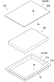
- FIG. 4 is a schematic perspective view showing the power storage device in an exploded manner.
- the exterior material 1 for a power storage device has a base material layer 3 as an outer layer, a sealant layer 4 as an inner layer, and between these two layers 3, 4. It is composed of a laminated body having a metal layer 2 as an arranged barrier layer in a laminated manner.
- the reference numeral “1a” in FIG. 1 is the inner surface of the exterior material 1
- the reference numeral “1b” is the outer surface of the exterior material 1.
- the base material layer 3 and the metal layer 2 are joined and integrated in a laminated manner in the order described above. More specifically, the base material layer 3 and the metal layer 2 are bonded to each other via the first adhesive layer 5a by, for example, the dry laminating method, and the metal layer 2 and the sealant layer 4 are bonded to each other via the first adhesive layer 5a by, for example, the dry laminating method. They are adhered to each other via the layer 5b.
- the exterior material 1 is generally a long strip, and the exterior material 1 is cut into a predetermined length and a predetermined shape before the power storage device main body is exteriorized by the exterior material 1.
- the exterior material coil 10 When storing or transporting the exterior material 1, it is common to store or transport the exterior material coil 10 manufactured by winding the exterior material 1 in a coil shape as shown in FIG. During storage and transportation, the exterior material coil 10 may be exposed to a temperature higher than room temperature (25 ° C.) of 35 ° C. to 70 ° C.
- the exterior material coil 10 is also manufactured by winding the exterior material 1 into a coil shape. It is common that aging is performed on the surface. At this time, the exterior material coil 10 is exposed to a temperature higher than room temperature of 35 ° C. to 65 ° C. by a predetermined aging device for aging (specifically, artificial aging).
- the three-dimensional surface texture parameters (Spc, S5p, SRC, Safc, Sk, Spp, Sdr, Sal, Vvc and Vmc) measured according to ISO25178 on the inner surface 1a of the exterior material 1 Using the value, F is defined by the following equation 1.
- Equation 1 a to j mean the values of the following three-dimensional surface texture parameters, and each parenthesis is the unit.
- a Arithmetic mean song of the mountain peak Spc (unit: mm -1 )
- b Gotenzan area height S5p (unit: ⁇ m)
- c Smooth rough crossover SRC (unit: ⁇ m 2 )
- d Erial Fractal Complexity Safc (Unit: Dimensionless)
- e Level difference Sk (unit: ⁇ m) of the core part
- f Extreme point height Spp (unit: ⁇ m)
- g Root mean square slope Sdr (unit:%)
- h Minimum autocorrelation length Sal (unit: ⁇ m)
- i Volume of space in the core part
- Vvc unit: mL / m 2
- j Volume of core part Vmc (unit: mL / m 2 ).
- the value of F (this value is also referred to as "F value” below) must be larger than 0 (that is, F> 0).
- the inner surface 1a of the exterior material 1 has an appropriate uneven shape, and when the exterior material 1 is wound in a coil shape, the adhesion between the exterior materials 1 and 1 is suppressed. Air is less likely to be trapped between the exterior materials 1 and 1. Therefore, even when the exterior material coil 10 is exposed to a high temperature state as described above, the generation of pressure marks is suppressed in the exterior material 1 (more specifically, the metal layer 2 of the exterior material 1). As a result, it is possible to suppress the occurrence of blisters on the outer surface 1b of the exterior material 1 after the exterior material 1 is molded into a predetermined shape.
- the upper limit of the F value is not limited and is usually 10 or less.
- the arithmetic mean song Spc at the peak of the mountain is preferably in the range of ⁇ 40 mm -1 to ⁇ 500 mm -1 .
- a particularly preferred range of Spc is -40 mm -1 to -100 mm -1 .
- the blister is a convex deformation / swelling that occurs on the outer surface 1b of the exterior material 1 after the exterior material 1 is molded into a predetermined shape such as a container.
- the size (diameter) of the blisters is generally 10 mm or more.
- the values of the above-mentioned three-dimensional surface texture parameters are measured in accordance with ISO25178 as described above, and specifically, they are measured by white light interference microscopy (vertical scanning low coherence interference method) or the like. ..
- the base material layer 3, the metal layer 2, and the sealant layer 4 constituting the exterior material 1 will be described below.
- the base material layer 3 is made of a resin, and more specifically, is made of a resin or the like having heat resistance at the temperature at the time of heat fusion carried out via the sealant layer 4.
- the base material layer 3 is formed of a biaxially stretched polyamide film, a biaxially stretched polybutylene terephthalate (PBT) film, a biaxially stretched polyethylene terephthalate (PET) film, a biaxially stretched polyethylene naphthalate (PEN) film, or the like. It is preferable to be done.
- PBT biaxially stretched polybutylene terephthalate
- PET biaxially stretched polyethylene terephthalate
- PEN biaxially stretched polyethylene naphthalate
- the base material layer 3 does not necessarily have to be made of a film, and may be made of, for example, a resin coat layer.
- the base material layer 3 may be formed of a single layer or a plurality of layers.
- the base material layer 3 is preferably made of a resin having a melting point higher than 10 ° C. with respect to all the resins constituting the sealant layer 4, and particularly preferably made of a resin having a melting point higher than 20 ° C.
- the thickness of the base material layer 3 is not limited, and is preferably 9 ⁇ m to 50 ⁇ m.
- a matte coat layer (not shown) or the like may be formed on the outer surface of the base material layer 3.
- the metal layer 2 is made of a metal foil or the like. Specifically, the metal layer 2 is formed of an aluminum foil, a copper foil, a stainless steel foil, a titanium foil, a nickel foil, a clad foil, or the like.
- a base treatment layer such as a chemical conversion treatment layer is formed on at least one of both surfaces of the metal foil (particularly preferably, the surface on the sealant layer 4 side). It is preferable to have. In this case, corrosion of the metal layer 2 due to the inclusions in the battery device body (eg, the electrolytic solution in the battery body) can be suppressed.
- the chemical conversion treatment to the metal foil is performed by, for example, the following method. That is, on the surface of the metal leaf that has been degreased, 1) Phosphoric acid and With chromic acid, An aqueous solution of a mixture containing at least one compound selected from the group consisting of a metal salt of fluoride and a non-metal salt of fluoride; 2) Phosphoric acid and At least one resin selected from the group consisting of acrylic resins, chitosan derivative resins and phenolic resins, and An aqueous solution of a mixture containing at least one compound selected from the group consisting of chromic acid and a chromium (III) salt; 3) Phosphoric acid and At least one resin selected from the group consisting of acrylic resins, chitosan derivative resins and phenolic resins, and At least one compound selected from the group consisting of chromic acid and chromium (III) salt, and An aqueous solution of a mixture containing at least one compound selected from
- the thickness of the metal layer 2 is not limited, and is preferably 20 ⁇ m to 100 ⁇ m.
- the sealant layer 4 is made of a thermoplastic resin (eg, a polyolefin resin) or the like. Specifically, the sealant layer 4 is formed of a polyolefin film or the like. As the polyolefin film, unstretched polypropylene (CPP) film or the like is used. When the sealant layer 4 is formed of a film, the film forming the sealant layer 4 is hereinafter also referred to as a sealant film.
- a thermoplastic resin eg, a polyolefin resin
- CPP unstretched polypropylene
- the sealant layer 4 may be composed of a single layer, but it is particularly preferable that the sealant layer 4 is composed of multiple layers as shown in FIG. 1, and further preferably formed of a multilayer film.
- the multilayer film has an innermost layer 4a arranged on the inner surface 1a side of the exterior material 1 and an outermost layer 4b arranged on the metal layer 2 side of the exterior material 1.
- the multilayer film includes the innermost layer 4a and the outermost layer 4b described above and at least one intermediate layer (not shown) arranged between these two layers 4a and 4b. Has.
- the multilayer film is made of polypropylene.
- the multilayer film is one in which two or more polypropylene random copolymer (rPP) layers and polypropylene block copolymer (bPP) layers are laminated and integrated.
- rPP polypropylene random copolymer
- bPP polypropylene block copolymer
- the rPP layer is arranged as the innermost layer 4a of the sealant layer 4 among the plurality of layers constituting the sealant layer 4.
- the thickness of the sealant layer 4 is not limited, and is preferably 20 ⁇ m to 100 ⁇ m.
- the sealant layer 4 contains a layer containing a lubricant.
- the friction between the exterior materials 1 and 1 of the exterior material coil 10 is reduced, so that damage to the inner surface 1a and the outer surface 1b of the exterior material 1 wound in a coil shape can be suppressed, and the exterior material 1 can be suppressed. Since it is difficult for air to be reliably trapped between 1 and 1, it is possible to reliably suppress the occurrence of blister on the exterior material 1.
- the lubricant-containing layer in the sealant layer 4 is arranged as at least the innermost layer 4a of the sealant layer 4. In this case, the above-mentioned effect of the lubricant can be surely achieved.
- the lubricant is for improving the slipperiness of the exterior material 1 during the molding process of the exterior material 1 to improve the molding processability of the exterior material 1, and further, when the exterior material 1 is wound in a coil shape.
- the purpose is to reduce friction between the exterior materials 1 and 1 of the exterior material coil 10 and suppress damage to the inner surface 1a and the outer surface 1b of the exterior material 1.
- the lubricant is generally contained in the sealant layer (resin) 4 by being added to the resin forming the sealant layer 4.
- the lubricant includes saturated fatty acid amides (eg, lauric acid amide, palmitic acid amide, stearic acid amide, behenic acid amide, hydroxystearic acid amide), unsaturated fatty acid amides (eg, oleic acid amide, erucic acid amide).
- saturated fatty acid amides eg, lauric acid amide, palmitic acid amide, stearic acid amide, behenic acid amide, hydroxystearic acid amide
- unsaturated fatty acid amides eg, oleic acid amide, erucic acid amide
- Substituted amides eg N-oleyl palmitate amide, N-stearyl stearic acid amide, N-stearyl oleic acid amide, N-oleyl stearic acid amide, N-stearyl erucic acid amide), methylol amide (eg methylol stearic acid) Amid), saturated fatty acid bisamides (eg, methylene bisstearic acid amides, ethylene biscapric acid amides, ethylene bislauric acid amides, ethylene bisstearic acid amides, ethylene bishydroxystearic acid amides, ethylene bisbechenic acid amides, hexamethylene bisstearic acid amides) Acid amides, hexamethylene bisbechenic acid amides, hexamethylene hydroxystearic acid amides, N, N'-distealyl adipic acid amides, N, N'-distearyl sevac
- the content of the lubricant is not limited, but when the sealant layer 4 is composed of a single layer, the content of the lubricant is preferably in the range of 100 ppm to 7,000 ppm with respect to the sealant layer 4, and the sealant layer 4 is not limited. When it is composed of multiple layers and the lubricant is contained in at least the innermost layer 4a of the sealant layer 4, the content of the lubricant is preferably in the range of 100 ppm to 7000 ppm with respect to the innermost layer 4a of the sealant layer 4.
- the sealant layer 4 of the exterior material 1 contains a lubricant and the exterior material coil 10 is exposed to a high temperature state as described above, the lubricant in the sealant layer 4 of the exterior material 1 becomes the exterior material.
- a very thin lubricant layer (not shown) is formed on the inner surface 1a by slightly exuding on the inner surface 1a of 1, and the exuded lubricant is further transferred to the outer surface 1b of the exterior material 1.
- a very thin lubricant layer (not shown) is also formed on the outer surface 1b.
- each lubricant layer is usually several nm, and therefore the presence of each lubricant layer has almost no effect on the above-mentioned three-dimensional surface property parameter values and F-numbers. There is.
- the adhesive of the first adhesive layer 5a is not limited, and specifically, an adhesive such as a polyurethane resin, an epoxy resin, or an acrylic resin (including a two-component curable adhesive) is used as the adhesive. Illustrated.
- the adhesive of the second adhesive layer 5b is not limited, and specifically, the adhesive includes an adhesive such as an olefin resin, an acid-modified olefin resin, and an epoxy resin (including a two-component curable adhesive). ) Is exemplified.
- the method of applying each adhesive layer 5a and 5b to the corresponding surface of the metal layer 2 is not limited, and examples thereof include a method of applying each adhesive layer 5a and 5b by gravure coating.
- the method that can surely obtain the exterior material that can suppress the occurrence of blisters after the molding process is as follows.
- an exterior material having an F value larger than 0 is selected from a plurality of exterior materials, and the selected exterior material is aged in a coiled state.
- the aging conditions at this time are not limited, and the aging temperature is preferably 30 ° C to 50 ° C. In this case, various strengths of the exterior material 1 such as the adhesive strength of the adhesive layers 5a and 5b can be surely increased.
- the aging time is, for example, 3 to 14 days.
- the method for surely obtaining the exterior material 1 having an F value larger than 0 is as follows.
- the values of the three-dimensional surface texture parameters of the inner surface 1a of the exterior material 1 are the uneven shape of the surface of the second adhesive layer 5b on the sealant film (sealant layer 4) side and the surface texture of the inner surface of the sealant film. Mainly depends. Therefore, a combination of the uneven shape of the surface of the second adhesive layer 5b and the surface texture of the inner surface of the sealant film so that the F value becomes larger than 0 is designed in advance by an experiment, and the exterior material is used with this combination. By manufacturing the above, it is possible to surely obtain an exterior material having an F value larger than 0.
- the above-mentioned inner surface of the sealant film is the surface of both surfaces of the sealant film on the side that becomes the inner surface 1a of the exterior material 1.
- the method for designing the uneven shape of the surface of the second adhesive layer 5b is not limited.
- the second adhesive layer 5b is applied to the surface of the metal layer 2 by gravure coating, gravure coating is applied.
- the conditions eg, the mesh shape of the gravure roll, the number of lines and the depth
- the uneven shape of the surface of the second adhesive layer 5b can be designed.
- the surface texture of the inner surface of the sealant film can be designed by adjusting the amount of anti-blocking agent added to the film, embossing the film, and so on.
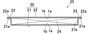
- the exterior material 1 of the present embodiment is used as a power storage device for exteriorizing, for example, a lithium ion secondary battery 25.
- the lithium ion secondary battery 25 includes a substantially rectangular parallelepiped battery main body 24 as a power storage device main body, and an outer container 20 that houses the battery main body 24 in a surrounding state.
- the outer container 20 includes an outer container main body 21 and an outer lid 22 corresponding to the outer container main body 21.
- the outer container main body 21 is manufactured by molding the exterior material 1 of the above embodiment into a container shape by a predetermined molding process (eg, overhang molding process, deep drawing molding process) so that the inner surface 1a thereof faces inward. It is a thing.
- a recess 21b for accommodating the battery body 24 is formed in the central portion of the inner surface 1a of the outer container main body 21, and a flange portion 21a as a planned joining portion bent outward is formed on the outer peripheral portion of the outer container main body 21. Is formed.
- the exterior lid 22 is the exterior material 1 of the above embodiment used in a flat state without being molded.
- the battery main body 24 is housed in the recess 21b of the outer container main body 21, and the outer lid 22 has its inner surface 1a facing the battery main body 24 side (lower side).
- the sealant is arranged on the outer container main body 21 and is the sealant layer 4 (see FIG. 1) of the flange portion 21a (scheduled joining portion) of the outer container main body 21 and the outer peripheral portion 22a as the planned joining portion of the outer lid 22.
- Reference numeral "23" in FIG. 3 is a joint portion (heat fusion portion) between the sealant layer 4 of the flange portion 21a of the outer container main body 21 and the sealant layer 4 of the outer peripheral portion 22a of the outer lid body 22.
- the inner surface 1a of the exterior material 1 forming the outer container body 21 faces the battery body 24 side, and the inner surface 1a of the exterior material 1 forming the exterior lid 22 also faces the battery body 24 side. There is.
- the tip of the tab lead connected to the battery body 24 is led out to the outside of the outer container 20, but the tab lead is not shown in FIGS. 3 and 4.
- the present invention is not limited to the above embodiment and can be variously modified without departing from the gist of the present invention.
- the power storage device body exteriord by the exterior material is not limited to the battery body of various batteries such as a lithium ion secondary battery, and other capacitor bodies of various capacitors and various capacitors. It may be a capacitor body or the like.
- a metal layer As a metal layer, a long strip-shaped aluminum foil (material: A8021-O (JIS H4160 standard)) having a thickness of 40 ⁇ m was prepared. Then, by applying chromate treatment to both surfaces of the aluminum foil, a chemical conversion film as a base treatment layer was formed.
- A8021-O JIS H4160 standard
- a long strip-shaped biaxially stretched 6 nylon film having a thickness of 25 ⁇ m is formed on one surface of the aluminum foil via a two-component curable urethane-based adhesive layer (first adhesive layer).
- first adhesive layer was adhered by a dry laminating method and wound into a coil. Adhesion by the dry laminating method was performed by sandwiching an aluminum foil and a biaxially stretched 6 nylon film between a rubber nip roll and a laminating roll heated to 100 ° C. Further, the coating of the first adhesive layer on one surface of the aluminum foil was performed by gravure coating.
- the above-mentioned aluminum foil wound in a coil shape was aged at 60 ° C. for 7 to 10 days.
- a long strip-shaped sealant film having a thickness of 80 ⁇ m is dry-laminated on the other surface of the aluminum foil to form a sealant layer via a two-component curable maleic acid-modified polypropylene adhesive layer (second adhesive layer). It was bonded by the method and wound into a coil. Adhesion by the dry laminating method was performed by sandwiching the aluminum foil and the sealant film between the rubber nip roll and the laminating roll heated to 100 ° C. Further, the coating of the second adhesive layer on the other surface of the aluminum foil was performed by gravure coating.
- sealant film a non-stretched film coextruded with three layers of rPP layer / bPP layer / rPP layer made of polypropylene containing a lubricant was used.
- a lubricant erucic acid amide was used.
- the lubricant content was 1000 ppm for each layer.
- the above-mentioned aluminum foil wound in a coil shape was aged at 40 ° C. for 7 to 10 days.
- this aluminum foil was unwound, inspected over its entire length, and the aluminum foil, which had no appearance defects such as pressure marks, was wound again into a coil to manufacture an exterior material coil.
- the width of the exterior material coil was 240 mm, and the winding length was 250 m.
- the thickness of the first adhesive layer of the exterior material was 4 ⁇ m, and the thickness of the second adhesive layer was 2 ⁇ m.
- Exterior material coils for multiple exterior materials with different inner surface surface textures by using multiple sealant films with different inner surface textures or by changing the uneven shape of the surface of the second adhesive layer on the sealant film side. was manufactured according to the method for manufacturing the exterior material coil described above.
- the three-dimensional surface texture parameters Spc, S5p, SRC, Safc, Sk, Spp, Sdr, Sal, Vvc and Vmc on the inner surface of the exterior material of each exterior material coil were measured.
- the specific measurement method applied at this time will be described later.
- the F value was calculated according to the above equation 1 using the values of these parameters.
- these exterior material coils were stored at 40 ° C for 2 days, and then the storage environment was moved to room temperature of 25 ° C and stored for 3 days.
- each exterior material coil was visually inspected over its entire length, and it was investigated whether or not each exterior material had an appearance defect such as a pressure mark. The results are shown in Tables 1 and 2.
- ⁇ The number of places where appearance defects occurred was 0 (that is, there was no appearance defects in the exterior material).
- the Spc when the Spc is in the range of -40 mm -1 to -500 mm -1 , the F value is surely made larger than 0. Therefore, it was confirmed that it is preferable that the Spc is in the range of ⁇ 40 mm -1 to ⁇ 500 mm -1 in order to surely suppress the occurrence of poor appearance.
- the values of the three-dimensional surface texture parameters were measured by white light interference microscopy (vertical scanning low coherence interference method) in accordance with ISO25178. ..
- the device used for this measurement was a scanning white interference microscope "VS1330" (manufactured by Hitachi High-Tech Co., Ltd.), the surface spatial resolution of which was 350 nm, and the resolution in the vertical direction was 0.01 nm.
- the present invention can be used for exterior materials and power storage devices for power storage devices such as lithium ion secondary batteries (LIB), lithium ion capacitors (LIC), electric double layer capacitors (EDLC), and all-solid-state batteries.
- LIB lithium ion secondary batteries
- LIC lithium ion capacitors
- EDLC electric double layer capacitors
- all-solid-state batteries such as lithium ion secondary batteries (LIB), lithium ion capacitors (LIC), electric double layer capacitors (EDLC), and all-solid-state batteries.
- Exterior material 1a Inner surface 1b: Outer surface 2: Metal layer 3: Base material layer 4: Sealant layer 5a, 5b: Adhesive layer 10: Exterior material coil 20: Exterior container 24: Battery body (power storage device body) 25: Lithium-ion secondary battery (power storage device)
Landscapes
- Chemical & Material Sciences (AREA)
- Chemical Kinetics & Catalysis (AREA)
- Electrochemistry (AREA)
- General Chemical & Material Sciences (AREA)
- Inorganic Chemistry (AREA)
- Laminated Bodies (AREA)
- Sealing Battery Cases Or Jackets (AREA)
- Packages (AREA)
- Electric Double-Layer Capacitors Or The Like (AREA)
Priority Applications (4)
| Application Number | Priority Date | Filing Date | Title |
|---|---|---|---|
| KR1020237030278A KR20230133399A (ko) | 2020-09-16 | 2021-09-14 | 축전 디바이스용 외장재, 축전 디바이스 및 축전 디바이스용 외장재의 제조 방법 |
| KR1020227043443A KR102577356B1 (ko) | 2020-09-16 | 2021-09-14 | 축전 디바이스용 외장재, 축전 디바이스 및 축전 디바이스용 외장재의 제조 방법 |
| CN202180045151.7A CN116096572B (zh) | 2020-09-16 | 2021-09-14 | 蓄电设备用外包装材料、蓄电设备及蓄电设备用外包装材料的制造方法 |
| CN202410651226.1A CN118380701A (zh) | 2020-09-16 | 2021-09-14 | 蓄电设备用外包装材料、蓄电设备及蓄电设备用外包装材料的制造方法 |
Applications Claiming Priority (2)
| Application Number | Priority Date | Filing Date | Title |
|---|---|---|---|
| JP2020-155255 | 2020-09-16 | ||
| JP2020155255A JP7634950B2 (ja) | 2020-09-16 | 2020-09-16 | 蓄電デバイス用外装材、蓄電デバイス及び蓄電デバイス用外装材の製造方法 |
Publications (1)
| Publication Number | Publication Date |
|---|---|
| WO2022059665A1 true WO2022059665A1 (ja) | 2022-03-24 |
Family
ID=80776086
Family Applications (1)
| Application Number | Title | Priority Date | Filing Date |
|---|---|---|---|
| PCT/JP2021/033687 Ceased WO2022059665A1 (ja) | 2020-09-16 | 2021-09-14 | 蓄電デバイス用外装材、蓄電デバイス及び蓄電デバイス用外装材の製造方法 |
Country Status (4)
| Country | Link |
|---|---|
| JP (1) | JP7634950B2 (https=) |
| KR (2) | KR20230133399A (https=) |
| CN (2) | CN118380701A (https=) |
| WO (1) | WO2022059665A1 (https=) |
Families Citing this family (3)
| Publication number | Priority date | Publication date | Assignee | Title |
|---|---|---|---|---|
| JP7484682B2 (ja) * | 2020-12-02 | 2024-05-16 | 王子ホールディングス株式会社 | 二軸延伸ポリプロピレンフィルム、金属層一体型ポリプロピレンフィルム、フィルムコンデンサ、及びフィルムロール |
| JP2024081908A (ja) * | 2022-12-07 | 2024-06-19 | Toppanホールディングス株式会社 | 蓄電デバイス用外装材及び蓄電デバイス |
| KR102668914B1 (ko) | 2022-12-29 | 2024-05-27 | 율촌화학 주식회사 | 고온 실링 강도가 유지 또는 증가되는 셀 파우치 필름 및 그 제조 방법 |
Citations (3)
| Publication number | Priority date | Publication date | Assignee | Title |
|---|---|---|---|---|
| JP2016081856A (ja) * | 2014-10-22 | 2016-05-16 | 昭和電工パッケージング株式会社 | 蓄電デバイス用外装材及び蓄電デバイス |
| JP2017112014A (ja) * | 2015-12-18 | 2017-06-22 | 大日本印刷株式会社 | 電池用包装材料 |
| WO2018066672A1 (ja) * | 2016-10-05 | 2018-04-12 | 大日本印刷株式会社 | 電池用包装材料、その製造方法及び電池 |
Family Cites Families (11)
| Publication number | Priority date | Publication date | Assignee | Title |
|---|---|---|---|---|
| JP2002184644A (ja) * | 2000-12-12 | 2002-06-28 | Toyobo Co Ltd | コンデンサー用ポリエステル系フィルムおよび該フィルムを用いたコンデンサー |
| JP2005203294A (ja) * | 2004-01-19 | 2005-07-28 | Toppan Printing Co Ltd | リチウムイオン電池用外装材 |
| EP2619005A1 (en) * | 2010-09-20 | 2013-07-31 | ExxonMobil Oil Corporation | Multi-layer films having improved sealing properties |
| JP5942384B2 (ja) * | 2011-11-07 | 2016-06-29 | 凸版印刷株式会社 | 二次電池用外装材及び二次電池 |
| JP6299553B2 (ja) * | 2014-10-16 | 2018-03-28 | 油化電子株式会社 | 電池外装用ラミネートフィルム及び電池 |
| JP6016987B1 (ja) * | 2015-05-29 | 2016-10-26 | 日新製鋼株式会社 | 電池外装用ステンレス箔、およびその製造方法 |
| CN106252533A (zh) * | 2015-06-10 | 2016-12-21 | 凸版印刷株式会社 | 蓄电装置用外装构件 |
| JP6767795B2 (ja) * | 2016-07-06 | 2020-10-14 | 昭和電工パッケージング株式会社 | 蓄電デバイス用外装材及びその製造方法 |
| JP6990505B2 (ja) | 2016-10-31 | 2022-01-12 | 昭和電工パッケージング株式会社 | 蓄電デバイス用外装材、蓄電デバイス用外装ケースおよび蓄電デバイス |
| JP6936093B2 (ja) * | 2017-09-28 | 2021-09-15 | 昭和電工パッケージング株式会社 | 蓄電デバイス用外装材、蓄電デバイス用外装ケース及び蓄電デバイス |
| JP6979847B2 (ja) * | 2017-10-16 | 2021-12-15 | 昭和電工パッケージング株式会社 | 蓄電デバイス用外装材及び蓄電デバイス |
-
2020
- 2020-09-16 JP JP2020155255A patent/JP7634950B2/ja active Active
-
2021
- 2021-09-14 KR KR1020237030278A patent/KR20230133399A/ko active Pending
- 2021-09-14 CN CN202410651226.1A patent/CN118380701A/zh active Pending
- 2021-09-14 KR KR1020227043443A patent/KR102577356B1/ko active Active
- 2021-09-14 CN CN202180045151.7A patent/CN116096572B/zh active Active
- 2021-09-14 WO PCT/JP2021/033687 patent/WO2022059665A1/ja not_active Ceased
Patent Citations (3)
| Publication number | Priority date | Publication date | Assignee | Title |
|---|---|---|---|---|
| JP2016081856A (ja) * | 2014-10-22 | 2016-05-16 | 昭和電工パッケージング株式会社 | 蓄電デバイス用外装材及び蓄電デバイス |
| JP2017112014A (ja) * | 2015-12-18 | 2017-06-22 | 大日本印刷株式会社 | 電池用包装材料 |
| WO2018066672A1 (ja) * | 2016-10-05 | 2018-04-12 | 大日本印刷株式会社 | 電池用包装材料、その製造方法及び電池 |
Also Published As
| Publication number | Publication date |
|---|---|
| JP2022049182A (ja) | 2022-03-29 |
| CN118380701A (zh) | 2024-07-23 |
| KR102577356B1 (ko) | 2023-09-13 |
| KR20230133399A (ko) | 2023-09-19 |
| JP7634950B2 (ja) | 2025-02-25 |
| KR20230009968A (ko) | 2023-01-17 |
| CN116096572B (zh) | 2024-06-14 |
| CN116096572A (zh) | 2023-05-09 |
Similar Documents
| Publication | Publication Date | Title |
|---|---|---|
| WO2022059665A1 (ja) | 蓄電デバイス用外装材、蓄電デバイス及び蓄電デバイス用外装材の製造方法 | |
| CN110576655B (zh) | 蓄电设备外包装用深拉深成型壳体及蓄电设备 | |
| JP6943547B2 (ja) | 蓄電デバイスの外装材用シーラントフィルム、蓄電デバイス用外装材及びその製造方法 | |
| JP7583143B2 (ja) | 蓄電デバイス用外装材 | |
| KR102426166B1 (ko) | 축전 디바이스의 외장재용 실런트 필름, 축전 디바이스용 외장재 및 그 제조 방법 | |
| JP2023160741A (ja) | 蓄電デバイス用包装材、蓄電デバイス用包装ケース及び蓄電デバイス | |
| JP7319484B1 (ja) | 蓄電デバイス用外装材および蓄電デバイス | |
| JP7142558B2 (ja) | 蓄電デバイス用外装材及び蓄電デバイス | |
| JP7033411B2 (ja) | 成形用包装材、蓄電デバイス用外装ケース及び蓄電デバイス | |
| JP7393569B2 (ja) | 蓄電デバイス用外装ケースの製造方法 | |
| JP7226979B2 (ja) | 蓄電デバイス用外装材及び蓄電デバイス | |
| US20260045604A1 (en) | Packaging material for power storage devices | |
| JP6936088B2 (ja) | 成形用包装材、蓄電デバイス用外装ケース及び蓄電デバイス | |
| JP6767795B2 (ja) | 蓄電デバイス用外装材及びその製造方法 | |
| KR20230150201A (ko) | 축전 디바이스용 포장재, 축전 디바이스용 포장 케이스 및 축전 디바이스 | |
| US20230411741A1 (en) | Packaging material for power storage device, packaging case for power storage device, and power storage device | |
| JP2023180219A (ja) | 蓄電デバイス用包装材、蓄電デバイス用包装ケース及び蓄電デバイス | |
| CN116979194A (zh) | 蓄电装置用包装材料、蓄电装置用包装壳体及蓄电装置 | |
| WO2026088965A1 (ja) | 蓄電デバイス用外装材、蓄電デバイス用外装ケース、及び蓄電デバイス | |
| JP6488827B2 (ja) | 電池用包装材料の巻取体 | |
| JP2024052936A (ja) | 蓄電デバイス用外装ケース及びその製造方法 |
Legal Events
| Date | Code | Title | Description |
|---|---|---|---|
| 121 | Ep: the epo has been informed by wipo that ep was designated in this application |
Ref document number: 21869352 Country of ref document: EP Kind code of ref document: A1 |
|
| ENP | Entry into the national phase |
Ref document number: 20227043443 Country of ref document: KR Kind code of ref document: A |
|
| NENP | Non-entry into the national phase |
Ref country code: DE |
|
| 122 | Ep: pct application non-entry in european phase |
Ref document number: 21869352 Country of ref document: EP Kind code of ref document: A1 |