WO2022054882A1 - 制御装置、内視鏡システムおよび制御方法 - Google Patents
制御装置、内視鏡システムおよび制御方法 Download PDFInfo
- Publication number
- WO2022054882A1 WO2022054882A1 PCT/JP2021/033205 JP2021033205W WO2022054882A1 WO 2022054882 A1 WO2022054882 A1 WO 2022054882A1 JP 2021033205 W JP2021033205 W JP 2021033205W WO 2022054882 A1 WO2022054882 A1 WO 2022054882A1
- Authority
- WO
- WIPO (PCT)
- Prior art keywords
- endoscope
- scene
- treatment tool
- treatment
- control device
- Prior art date
- Legal status (The legal status is an assumption and is not a legal conclusion. Google has not performed a legal analysis and makes no representation as to the accuracy of the status listed.)
- Ceased
Links
Images











Classifications
-
- A—HUMAN NECESSITIES
- A61—MEDICAL OR VETERINARY SCIENCE; HYGIENE
- A61B—DIAGNOSIS; SURGERY; IDENTIFICATION
- A61B1/00—Instruments for performing medical examinations of the interior of cavities or tubes of the body by visual or photographical inspection, e.g. endoscopes; Illuminating arrangements therefor
- A61B1/00002—Operational features of endoscopes
- A61B1/00043—Operational features of endoscopes provided with output arrangements
- A61B1/00045—Display arrangement
- A61B1/0005—Display arrangement combining images e.g. side-by-side, superimposed or tiled
-
- A—HUMAN NECESSITIES
- A61—MEDICAL OR VETERINARY SCIENCE; HYGIENE
- A61B—DIAGNOSIS; SURGERY; IDENTIFICATION
- A61B34/00—Computer-aided surgery; Manipulators or robots specially adapted for use in surgery
- A61B34/30—Surgical robots
-
- A—HUMAN NECESSITIES
- A61—MEDICAL OR VETERINARY SCIENCE; HYGIENE
- A61B—DIAGNOSIS; SURGERY; IDENTIFICATION
- A61B1/00—Instruments for performing medical examinations of the interior of cavities or tubes of the body by visual or photographical inspection, e.g. endoscopes; Illuminating arrangements therefor
- A61B1/00002—Operational features of endoscopes
- A61B1/00004—Operational features of endoscopes characterised by electronic signal processing
- A61B1/00006—Operational features of endoscopes characterised by electronic signal processing of control signals
-
- A—HUMAN NECESSITIES
- A61—MEDICAL OR VETERINARY SCIENCE; HYGIENE
- A61B—DIAGNOSIS; SURGERY; IDENTIFICATION
- A61B1/00—Instruments for performing medical examinations of the interior of cavities or tubes of the body by visual or photographical inspection, e.g. endoscopes; Illuminating arrangements therefor
- A61B1/00002—Operational features of endoscopes
- A61B1/00004—Operational features of endoscopes characterised by electronic signal processing
- A61B1/00009—Operational features of endoscopes characterised by electronic signal processing of image signals during a use of endoscope
-
- A—HUMAN NECESSITIES
- A61—MEDICAL OR VETERINARY SCIENCE; HYGIENE
- A61B—DIAGNOSIS; SURGERY; IDENTIFICATION
- A61B1/00—Instruments for performing medical examinations of the interior of cavities or tubes of the body by visual or photographical inspection, e.g. endoscopes; Illuminating arrangements therefor
- A61B1/00002—Operational features of endoscopes
- A61B1/00039—Operational features of endoscopes provided with input arrangements for the user
- A61B1/0004—Operational features of endoscopes provided with input arrangements for the user for electronic operation
-
- A—HUMAN NECESSITIES
- A61—MEDICAL OR VETERINARY SCIENCE; HYGIENE
- A61B—DIAGNOSIS; SURGERY; IDENTIFICATION
- A61B1/00—Instruments for performing medical examinations of the interior of cavities or tubes of the body by visual or photographical inspection, e.g. endoscopes; Illuminating arrangements therefor
- A61B1/00002—Operational features of endoscopes
- A61B1/00039—Operational features of endoscopes provided with input arrangements for the user
- A61B1/00042—Operational features of endoscopes provided with input arrangements for the user for mechanical operation
-
- A—HUMAN NECESSITIES
- A61—MEDICAL OR VETERINARY SCIENCE; HYGIENE
- A61B—DIAGNOSIS; SURGERY; IDENTIFICATION
- A61B1/00—Instruments for performing medical examinations of the interior of cavities or tubes of the body by visual or photographical inspection, e.g. endoscopes; Illuminating arrangements therefor
- A61B1/00002—Operational features of endoscopes
- A61B1/00043—Operational features of endoscopes provided with output arrangements
- A61B1/00045—Display arrangement
-
- A—HUMAN NECESSITIES
- A61—MEDICAL OR VETERINARY SCIENCE; HYGIENE
- A61B—DIAGNOSIS; SURGERY; IDENTIFICATION
- A61B1/00—Instruments for performing medical examinations of the interior of cavities or tubes of the body by visual or photographical inspection, e.g. endoscopes; Illuminating arrangements therefor
- A61B1/00147—Holding or positioning arrangements
- A61B1/00149—Holding or positioning arrangements using articulated arms
-
- A—HUMAN NECESSITIES
- A61—MEDICAL OR VETERINARY SCIENCE; HYGIENE
- A61B—DIAGNOSIS; SURGERY; IDENTIFICATION
- A61B1/00—Instruments for performing medical examinations of the interior of cavities or tubes of the body by visual or photographical inspection, e.g. endoscopes; Illuminating arrangements therefor
- A61B1/00147—Holding or positioning arrangements
- A61B1/0016—Holding or positioning arrangements using motor drive units
-
- A—HUMAN NECESSITIES
- A61—MEDICAL OR VETERINARY SCIENCE; HYGIENE
- A61B—DIAGNOSIS; SURGERY; IDENTIFICATION
- A61B1/00—Instruments for performing medical examinations of the interior of cavities or tubes of the body by visual or photographical inspection, e.g. endoscopes; Illuminating arrangements therefor
- A61B1/04—Instruments for performing medical examinations of the interior of cavities or tubes of the body by visual or photographical inspection, e.g. endoscopes; Illuminating arrangements therefor combined with photographic or television appliances
- A61B1/045—Control thereof
-
- A—HUMAN NECESSITIES
- A61—MEDICAL OR VETERINARY SCIENCE; HYGIENE
- A61B—DIAGNOSIS; SURGERY; IDENTIFICATION
- A61B34/00—Computer-aided surgery; Manipulators or robots specially adapted for use in surgery
- A61B34/30—Surgical robots
- A61B34/32—Surgical robots operating autonomously
-
- A—HUMAN NECESSITIES
- A61—MEDICAL OR VETERINARY SCIENCE; HYGIENE
- A61B—DIAGNOSIS; SURGERY; IDENTIFICATION
- A61B5/00—Measuring for diagnostic purposes; Identification of persons
- A61B5/06—Devices, other than using radiation, for detecting or locating foreign bodies ; Determining position of diagnostic devices within or on the body of the patient
- A61B5/065—Determining position of the probe employing exclusively positioning means located on or in the probe, e.g. using position sensors arranged on the probe
-
- G—PHYSICS
- G02—OPTICS
- G02B—OPTICAL ELEMENTS, SYSTEMS OR APPARATUS
- G02B23/00—Telescopes, e.g. binoculars; Periscopes; Instruments for viewing the inside of hollow bodies; Viewfinders; Optical aiming or sighting devices
- G02B23/24—Instruments or systems for viewing the inside of hollow bodies, e.g. fibrescopes
-
- G—PHYSICS
- G06—COMPUTING OR CALCULATING; COUNTING
- G06T—IMAGE DATA PROCESSING OR GENERATION, IN GENERAL
- G06T3/00—Geometric image transformations in the plane of the image
- G06T3/60—Rotation of whole images or parts thereof
-
- G—PHYSICS
- G06—COMPUTING OR CALCULATING; COUNTING
- G06T—IMAGE DATA PROCESSING OR GENERATION, IN GENERAL
- G06T7/00—Image analysis
- G06T7/70—Determining position or orientation of objects or cameras
-
- H—ELECTRICITY
- H04—ELECTRIC COMMUNICATION TECHNIQUE
- H04N—PICTORIAL COMMUNICATION, e.g. TELEVISION
- H04N23/00—Cameras or camera modules comprising electronic image sensors; Control thereof
- H04N23/60—Control of cameras or camera modules
- H04N23/62—Control of parameters via user interfaces
-
- H—ELECTRICITY
- H04—ELECTRIC COMMUNICATION TECHNIQUE
- H04N—PICTORIAL COMMUNICATION, e.g. TELEVISION
- H04N23/00—Cameras or camera modules comprising electronic image sensors; Control thereof
- H04N23/60—Control of cameras or camera modules
- H04N23/667—Camera operation mode switching, e.g. between still and video, sport and normal or high- and low-resolution modes
-
- A—HUMAN NECESSITIES
- A61—MEDICAL OR VETERINARY SCIENCE; HYGIENE
- A61B—DIAGNOSIS; SURGERY; IDENTIFICATION
- A61B1/00—Instruments for performing medical examinations of the interior of cavities or tubes of the body by visual or photographical inspection, e.g. endoscopes; Illuminating arrangements therefor
- A61B1/00002—Operational features of endoscopes
- A61B1/00004—Operational features of endoscopes characterised by electronic signal processing
- A61B1/00009—Operational features of endoscopes characterised by electronic signal processing of image signals during a use of endoscope
- A61B1/000094—Operational features of endoscopes characterised by electronic signal processing of image signals during a use of endoscope extracting biological structures
-
- A—HUMAN NECESSITIES
- A61—MEDICAL OR VETERINARY SCIENCE; HYGIENE
- A61B—DIAGNOSIS; SURGERY; IDENTIFICATION
- A61B1/00—Instruments for performing medical examinations of the interior of cavities or tubes of the body by visual or photographical inspection, e.g. endoscopes; Illuminating arrangements therefor
- A61B1/00002—Operational features of endoscopes
- A61B1/00004—Operational features of endoscopes characterised by electronic signal processing
- A61B1/00009—Operational features of endoscopes characterised by electronic signal processing of image signals during a use of endoscope
- A61B1/000096—Operational features of endoscopes characterised by electronic signal processing of image signals during a use of endoscope using artificial intelligence
-
- A—HUMAN NECESSITIES
- A61—MEDICAL OR VETERINARY SCIENCE; HYGIENE
- A61B—DIAGNOSIS; SURGERY; IDENTIFICATION
- A61B1/00—Instruments for performing medical examinations of the interior of cavities or tubes of the body by visual or photographical inspection, e.g. endoscopes; Illuminating arrangements therefor
- A61B1/00163—Optical arrangements
- A61B1/00193—Optical arrangements adapted for stereoscopic vision
-
- A—HUMAN NECESSITIES
- A61—MEDICAL OR VETERINARY SCIENCE; HYGIENE
- A61B—DIAGNOSIS; SURGERY; IDENTIFICATION
- A61B34/00—Computer-aided surgery; Manipulators or robots specially adapted for use in surgery
- A61B34/20—Surgical navigation systems; Devices for tracking or guiding surgical instruments, e.g. for frameless stereotaxis
- A61B2034/2046—Tracking techniques
- A61B2034/2055—Optical tracking systems
-
- A—HUMAN NECESSITIES
- A61—MEDICAL OR VETERINARY SCIENCE; HYGIENE
- A61B—DIAGNOSIS; SURGERY; IDENTIFICATION
- A61B34/00—Computer-aided surgery; Manipulators or robots specially adapted for use in surgery
- A61B34/20—Surgical navigation systems; Devices for tracking or guiding surgical instruments, e.g. for frameless stereotaxis
- A61B2034/2046—Tracking techniques
- A61B2034/2065—Tracking using image or pattern recognition
-
- A—HUMAN NECESSITIES
- A61—MEDICAL OR VETERINARY SCIENCE; HYGIENE
- A61B—DIAGNOSIS; SURGERY; IDENTIFICATION
- A61B34/00—Computer-aided surgery; Manipulators or robots specially adapted for use in surgery
- A61B34/20—Surgical navigation systems; Devices for tracking or guiding surgical instruments, e.g. for frameless stereotaxis
- A61B2034/2068—Surgical navigation systems; Devices for tracking or guiding surgical instruments, e.g. for frameless stereotaxis using pointers, e.g. pointers having reference marks for determining coordinates of body points
-
- A—HUMAN NECESSITIES
- A61—MEDICAL OR VETERINARY SCIENCE; HYGIENE
- A61B—DIAGNOSIS; SURGERY; IDENTIFICATION
- A61B34/00—Computer-aided surgery; Manipulators or robots specially adapted for use in surgery
- A61B34/30—Surgical robots
- A61B2034/301—Surgical robots for introducing or steering flexible instruments inserted into the body, e.g. catheters or endoscopes
-
- A—HUMAN NECESSITIES
- A61—MEDICAL OR VETERINARY SCIENCE; HYGIENE
- A61B—DIAGNOSIS; SURGERY; IDENTIFICATION
- A61B34/00—Computer-aided surgery; Manipulators or robots specially adapted for use in surgery
- A61B34/30—Surgical robots
- A61B2034/305—Details of wrist mechanisms at distal ends of robotic arms
-
- A—HUMAN NECESSITIES
- A61—MEDICAL OR VETERINARY SCIENCE; HYGIENE
- A61B—DIAGNOSIS; SURGERY; IDENTIFICATION
- A61B90/00—Instruments, implements or accessories specially adapted for surgery or diagnosis and not covered by any of the groups A61B1/00 - A61B50/00, e.g. for luxation treatment or for protecting wound edges
- A61B90/36—Image-producing devices or illumination devices not otherwise provided for
- A61B2090/363—Use of fiducial points
-
- A—HUMAN NECESSITIES
- A61—MEDICAL OR VETERINARY SCIENCE; HYGIENE
- A61B—DIAGNOSIS; SURGERY; IDENTIFICATION
- A61B34/00—Computer-aided surgery; Manipulators or robots specially adapted for use in surgery
- A61B34/25—User interfaces for surgical systems
-
- A—HUMAN NECESSITIES
- A61—MEDICAL OR VETERINARY SCIENCE; HYGIENE
- A61B—DIAGNOSIS; SURGERY; IDENTIFICATION
- A61B5/00—Measuring for diagnostic purposes; Identification of persons
- A61B5/68—Arrangements of detecting, measuring or recording means, e.g. sensors, in relation to patient
- A61B5/6846—Arrangements of detecting, measuring or recording means, e.g. sensors, in relation to patient specially adapted to be brought in contact with an internal body part, i.e. invasive
- A61B5/6847—Arrangements of detecting, measuring or recording means, e.g. sensors, in relation to patient specially adapted to be brought in contact with an internal body part, i.e. invasive mounted on an invasive device
-
- G—PHYSICS
- G06—COMPUTING OR CALCULATING; COUNTING
- G06T—IMAGE DATA PROCESSING OR GENERATION, IN GENERAL
- G06T2207/00—Indexing scheme for image analysis or image enhancement
- G06T2207/10—Image acquisition modality
- G06T2207/10004—Still image; Photographic image
- G06T2207/10012—Stereo images
-
- G—PHYSICS
- G06—COMPUTING OR CALCULATING; COUNTING
- G06T—IMAGE DATA PROCESSING OR GENERATION, IN GENERAL
- G06T2207/00—Indexing scheme for image analysis or image enhancement
- G06T2207/10—Image acquisition modality
- G06T2207/10068—Endoscopic image
-
- G—PHYSICS
- G06—COMPUTING OR CALCULATING; COUNTING
- G06T—IMAGE DATA PROCESSING OR GENERATION, IN GENERAL
- G06T2207/00—Indexing scheme for image analysis or image enhancement
- G06T2207/30—Subject of image; Context of image processing
- G06T2207/30004—Biomedical image processing
-
- G—PHYSICS
- G06—COMPUTING OR CALCULATING; COUNTING
- G06T—IMAGE DATA PROCESSING OR GENERATION, IN GENERAL
- G06T2207/00—Indexing scheme for image analysis or image enhancement
- G06T2207/30—Subject of image; Context of image processing
- G06T2207/30244—Camera pose
Definitions
- the present invention relates to a control device, an endoscope system and a control method, and more particularly to a control device, an endoscope system and a control method for controlling the endoscope to follow a treatment tool.
- the region C is an endoscope even though the operator wants to observe the region C in front of the traveling direction of the electric knife 6. It is placed at the upper right corner of the mirror image B or outside.
- the region C is the endoscopic image B even though the operator wants to observe the region C between the two forceps 6. Placed on the left edge of or outside.
- the present invention has been made in view of the above circumstances, and is a control device, an endoscopic system, and a control method capable of arranging a treatment tool at an appropriate position in an endoscopic image according to a treatment scene.
- the purpose is to provide.
- One aspect of the present invention is a control device that controls the movement of the endoscope and causes the treatment tool to follow the endoscope, and includes a processor, and the processor acquires position information including the position of the treatment tool. Then, the scene information is acquired, the scene information is information related to the treatment scene observed by the endoscope, and the offset parameter of the target point is determined based on the scene information, and the offset parameter is the above-mentioned.
- the control device causes the treatment tool to follow the endoscope so that the treatment tool is arranged at the target point.
- Another aspect of the present invention includes an endoscope, a moving device for moving the endoscope in a subject, and the above-mentioned control device for controlling the moving device to make the endoscope follow a treatment tool. It is an endoscope system equipped with.
- Another aspect of the present invention is a control method for controlling the movement of the endoscope and causing the treatment tool to follow the endoscope, the step of acquiring position information including the position of the treatment tool, and scene information.
- the scene information is information related to the treatment scene observed by the endoscope
- the process and the offset parameter of the target point are determined based on the scene information
- the offset parameter is the endoscopy.
- the treatment tool can be arranged at an appropriate position in the endoscopic image according to the treatment scene.
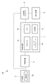
- It is a functional block diagram of the control device of the endoscope system of FIG. It is a figure explaining the reference point and the target point set in the field of view of an endoscope.
- FIG. 18 is an endoscopic image showing the position of a target point in the position and posture of FIG. 18A.
- FIG. 19A is an endoscopic image showing the position of a target point in the position and posture of FIG. 19A. It is a figure explaining the 2D or 3D target point set in the field of view of an endoscope. It is a figure explaining the 2D or 3D target point in an endoscopic image. It is an external view of the whole structure of the modification of the endoscope system of FIG. FIG. 3 is an external view of the overall configuration of another modification of the endoscope system of FIG. 1. This is an example of an endoscopic image of a conventional peeling scene. This is an example of an endoscopic image of a conventional development scene.
- the control device, the endoscope system, and the control method according to the first embodiment of the present invention will be described with reference to the drawings.
- the endoscope system 10 in the endoscope system 10 according to the present embodiment, the endoscope 2 and the treatment tool 6 of 1 or more are inserted into the body of the patient P who is the subject, and the treatment tool 6 is endoscopically viewed. It is used in surgery to treat the treatment target site with the treatment tool 6 while observing with the mirror 2, and is used, for example, in laparoscopic surgery.
- the endoscope system 10 is connected to the endoscope 2, the moving device 3 for moving the endoscope 2 inside the patient P, and the endoscope 2 for endoscopy.
- the endoscope processor 4 that processes the endoscope image acquired by the mirror 2, the control device 1 that is connected to the moving device 3 and the endoscope processor 4 and controls the moving device 3, and the endoscope processor 4 are connected. It is provided with a display device 5 for displaying an endoscopic image.
- the endoscope 2 is, for example, a rigid mirror, and includes an image pickup unit 2a that has an image pickup element and acquires an endoscope image B.
- the imaging unit 2a is, for example, a three-dimensional camera provided at the tip of the endoscope 2, and acquires a stereo image including the tip 6a of the treatment tool 6 as an endoscope image B (see, for example, FIG. 3B). do.
- the image pickup unit 2a is an image sensor such as a CCD (Charge Coupled Device) image sensor or a CMOS (Complementary Metal Oxide Semiconductor) image sensor, and converts the light received from a predetermined area into an electric signal by photoelectric conversion. To generate an image of a predetermined area.
- the stereo image which is the endoscope image E, is generated by image processing two images having parallax by an endoscope processor 4 or the like.
- the endoscope image B is transmitted from the endoscope 2 to the endoscope processor 4, is subjected to necessary processing in the endoscope processor 4, is transmitted from the endoscope processor 4 to the display device 5, and is transmitted to the display device 5. Is displayed in. The operator operates the treatment tool 6 inserted in the body while observing the endoscopic image B displayed on the display device 5.
- the display device 5 is an arbitrary display such as a liquid crystal display or an organic EL display.
- the display device 5 may include a voice device such as a speaker.
- a terminal used by the user to communicate with the control device 1 and the endoscope processor 4 through a communication network may be provided, and the endoscope image E may be displayed on the terminal.
- the terminal is not particularly limited, but may be a notebook computer, a laptop computer, a tablet computer, a smartphone, or the like.
- the moving device 3 includes a robot arm 3a (including an electric scope holder) that is connected to the base end of the endoscope 2 and three-dimensionally controls the position and posture of the endoscope 2.
- the moving device 3 of FIG. 1 includes a robot arm 3a having a plurality of joints 3b, and moves the endoscope 2 three-dimensionally by the movement of the joints 3b to three-dimensionally move the position and posture of the endoscope 2. Can be changed.
- the control device 1 includes at least one processor 1a such as a central processing unit, a memory 1b, a storage unit 1c, and a user interface 1d.
- the control device 1 may be, for example, a desktop computer, a tablet computer, a laptop computer, a smartphone, a mobile phone, or the like.
- the processor 1a may be a single processor, a multi-processor or a multi-core processor.
- the processor 1a reads and executes the program stored in the storage unit 1c.
- the memory 1b is, for example, a ROM (read-only memory) or a semiconductor memory including a RAM (Random Access Memory) area.
- the memory 1b may also store data necessary for processing of the processor 1a (that is, may operate as a “storage unit”), similarly to the storage unit 1c described later.
- the storage unit 1c is a non-volatile recording medium including a semiconductor memory such as a hard disk or a flash memory, and stores programs and data necessary for the processor 1a to execute processing.
- the processor 1a executes the process according to the program read into the memory 1b, the functions of the respective parts 11, 12, 13, and 14 described later are realized.
- Some functions of the control device 1 are FPGA (Field Programmable Gate Array), SOC (System-on-a-Chip), ASIC (Application Specific Integrated Circuit), PLC (Programmable Logic) dedicated circuit, and PLD (Programmable Logic) dedicated circuit. It may be realized by hardware or the like.
- the control device 1 has a manual mode and a follow-up mode, and switches between the manual mode and the follow-up mode based on the instruction of an operator such as an operator, for example, based on the voice of the operator.
- the manual mode is a mode in which the operator manually operates the endoscope 2. In the manual mode, for example, the operator can remotely control the robot arm 3a or the electric holder by operating an operating device (not shown) connected to the control device 1.
- the follow-up mode is a mode in which the control device 1 controls the moving device 3 to automatically follow the endoscope 2 to the treatment tool 6 set as the follow-up target.
- the control device 1 acquires the three-dimensional position of the tip 6a of the treatment tool 6, the three-dimensional position of the tip 6a, and the target point T 3 in the field of view F.
- the moving device 3 is controlled based on the dimensional position.
- the control device 1 controls the movement of the endoscope 2 and causes the treatment tool 6 to follow the endoscope 2 so that the target point T is arranged at the tip 6a.
- the direction parallel to the optical axis A of the endoscope 2 is the X direction
- the direction orthogonal to the optical axis A and corresponding to the lateral direction of the endoscope image B is the Y direction
- light The direction orthogonal to the axis A and corresponding to the vertical direction of the endoscopic image B is the Z direction.
- the target point T is initially set at the reference point O on the optical axis A, which is separated from the tip 2b of the endoscope 2 by a predetermined distance D in the direction parallel to the optical axis A.
- the control device 1 three-dimensionally offsets the target point T from the reference point O to another position in the visual field F according to the treatment scene observed by the endoscope 2. Therefore, the position of the tip 6a in the endoscope image B changes depending on the treatment scene between the center of the endoscope image B and the position offset from the center.
- the control device 1 sets the offset parameter based on the position information acquisition unit 11 for acquiring the position information, the scene information acquisition unit 12 for acquiring the scene information, and the scene information. It includes an offset parameter determination unit 13 for determining, and a control unit 14 for controlling the position and orientation of the endoscope 2 based on the offset parameter and position information.
- the position information acquisition unit 11 acquires the position information of the object existing in the endoscope image B from the endoscope processor 4.
- the position information includes at least the three-dimensional position of the tip 6a of the treatment tool 6. Therefore, the endoscope processor 4 executes a process of calculating the position information including the three-dimensional position of the tip 6a from the endoscope image B.
- the process of calculating the position information may be executed by the position information acquisition unit 11.
- the scene information is information related to the treatment scene observed by the endoscope 2.
- the movement of the treatment tool 6 differs depending on the treatment scene. For example, in a peeling scene in which a living tissue is peeled off by the treatment tool 6, the operator slowly moves the treatment tool 6.
- the scene information acquisition unit 12 acquires a three-dimensional movement vector (velocity vector) V of the treatment tool 6 representing the movement of the treatment tool 6 as scene information.
- the scene information acquisition unit 12 detects the movement vector V from the endoscope image B as shown in FIG. 4A, or the movement vector from the movement of the endoscope 2 as shown in FIG. Detect V.
- the scene information acquisition unit 12 may acquire the movement vector V by using any method other than these.
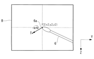
- the movement vector V is detected from two or more endoscope images B at different times. Specifically, the movement vector V is calculated from the following equation.
- V P1-P2
- P1 is a three-dimensional position vector (x1, y1, z1) of the tip 6a in the endoscope image B at time t
- P2 is in the endoscope image B at time t + ⁇ t after ⁇ t from time t. It is a three-dimensional position vector (x2, y2, z2) of the tip 6a.
- the endoscope image B is input to the control device 1 directly from the endoscope 2 or via the endoscope processor 4.
- the movement vector V is detected from the movement of the endoscope 2 following the treatment tool 6. That is, since the endoscope 2 follows the treatment tool 6 so that the tip 6a of the treatment tool 6 and the tip 2b of the endoscope 2 maintain a predetermined positional relationship, the movement of the tip 2b of the endoscope 2 is performed. It has a certain relationship with the movement of the tip 6a of the treatment tool 6.
- the offset parameter determination unit 13 determines the offset parameter based on the movement vector V.
- the offset parameter is a parameter that determines the position of the target point T with respect to the reference point O, and is, for example, a parameter representing the offset direction and the offset distance of the target point T with respect to the reference point O.
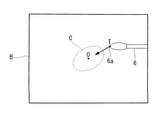
- the offset parameter determination unit 13 looks at the region C in front of the treatment tool 6 in the movement direction of the treatment tool 6 based on the direction of the movement vector V. Determine the offset parameter to be placed in the center of F (ie, on the optical axis A).
- the arrows indicate the moving direction of the treatment tool 6.
- the offset parameter determination unit 13 calculates a three-dimensional vector in the direction opposite to the movement vector V as an offset parameter by substituting the movement vector V into a predetermined function F (V).
- the offset parameter determination unit 13 determines whether or not the magnitude
- the control unit 14 calculates the three-dimensional position of the target point T for arranging the region C in front of the treatment tool 6 in the moving direction at the center of the visual field F. For example, the control unit 14 calculates a position offset by the magnitude of the three-dimensional vector (-k * V) in the direction of the three-dimensional vector (-k * V) from the reference point O as the three-dimensional position of the target point T. do. Next, the control unit 14 offsets the target point T from the reference point O by setting the target point T at the calculated three-dimensional position. Further, the control unit 14 receives information on the three-dimensional position of the tip 6a of the treatment tool 6 from the position information acquisition unit 11.
- the control unit 14 calculates the position and posture of the tip 2b of the endoscope 2 in which the target point T is arranged at the three-dimensional position of the tip 6a.
- the control unit 14 calculates the amount of movement of the moving device 3 for arranging the tip 2b at the calculated position and posture (for example, the rotation angle of each joint 3b), and the moving device by the calculated amount of movement. 3 is operated.
- the tip 2b of the endoscope 2 follows the tip 6a of the treatment tool 6, and the target point T moves toward the tip 6a.
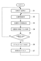
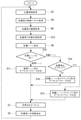
- control device 1 When the mode is switched to the tracking mode, the processor 1a of the control device 1 automatically causes the treatment tool 6 to follow the endoscope 2 by executing steps S1 to S7 shown in FIG. 7.
- the control unit 14 At the start of the follow-up mode, the control unit 14 initially sets the target point T at the reference point O, which is the center of the field of view F of the endoscope 2 (step S1).
- the position information acquisition unit 11 acquires position information including the three-dimensional position of the tip 6a of the treatment tool 6 (step S2).
- the control unit 14 causes the tip 6a of the treatment tool 6 to follow the tip 2b of the endoscope 2 so that the tip 6a is arranged at the target point T (step S3).
- the control unit 14 controls the moving device 3 based on the three-dimensional positions of the tip 6a and the target point T, and performs endoscopy so that the target point T in the visual field F is arranged at the position of the tip 6a. Move the mirror 2.
- the processes of steps S4 to S7 for adjusting the position of the target point T are executed.
- the scene information acquisition unit 12 acquires the movement vector V of the treatment tool 6 (step S4).
- of the movement vector is larger than the threshold value ⁇ (NO in step S5), the processes of steps S6 and S7 are not executed, and the control unit 14 maintains the target point T at the reference point O (step). S1). Therefore, the endoscope 2 follows the treatment tool 6 so that the tip 6a is arranged at the center in the endoscope image B.
- the offset parameter determination unit 13 determines the region C in front of the moving direction of the treatment tool 6 based on the moving vector V.
- the offset parameter to be placed at the reference point O is determined (step S6).
- the control unit 14 sets the target point T at a position offset from the reference point O in the direction opposite to the movement vector V based on the offset parameter (step S7). Therefore, the endoscope 2 follows the treatment tool 6 so that the tip 6a of the treatment tool 6 is arranged at the target point T offset from the center of the endoscope image B.
- the target point T is offset from the reference point O at the center of the visual field F in the direction opposite to the movement direction of the treatment tool 6.
- the tip 6a is offset from the center of the endoscope image B in the direction opposite to the peeling direction, and the region C to be peeled from the tip 6a is arranged at the center in the endoscope image B.
- the tip 6a of the treatment tool 6 in the endoscopic image B is treated at present by offsetting the target point T three-dimensionally from the reference point O based on the movement vector of the treatment tool 6. It can be placed in a position suitable for the scene.
- the tip 6a is arranged at a position offset from the reference point O in the direction opposite to the movement direction of the treatment tool 6, and the treatment tool 6 is arranged.
- the region C in front of the moving direction that is, the region to be separated from the region C, is arranged at the center of the endoscopic image B. Therefore, the operator can easily observe the area C to be peeled off.
- the offset parameter determination unit 13 determines the offset parameter using the function F (V), but instead, the movement vector V and the offset parameter are associated with each other.
- the offset parameters may be determined using Table E.
- FIG. 8 shows an example of the parameter table E.
- the parameter table E three regions E1, E2, and E3 of low speed, medium speed, and high speed are set according to the magnitude
- the relationship between the offset distance ⁇ 1 in the region E1, the offset distance ⁇ 2 in the region E2, and the offset distance ⁇ 3 in the region E3 is ⁇ 1 ⁇ 2 ⁇ 3.
- corresponds to the medium speed region E2
- the position offset from the reference point O by the offset distance ⁇ 2 in the direction opposite to the movement vector V is the target point T.
- FIG. 9 shows a control method when the parameter table E is used. As shown in FIG. 9, step S5 is omitted and the offset parameter determination is repeated regardless of
- the present embodiment differs from the first embodiment in that the offset parameter is determined based on the movement vector V and the type of the treatment tool 6.
- the present embodiment a configuration different from that of the first embodiment will be described, and the same reference numerals will be given to the configurations common to the first embodiment, and the description thereof will be omitted.
- the endoscope system 10 includes a control device 1, an endoscope 2, a moving device 3, an endoscope processor 4, and a display device 5.
- the control device 1 further includes a scene estimation unit 15 in addition to the position information acquisition unit 11, the scene information acquisition unit 12, the offset parameter determination unit 13, and the control unit 14.
- the function of the scene estimation unit 15 is realized by the processor 1a like the other units 11, 12, 13, and 14.
- the scene information acquisition unit 12 acquires the type of the treatment tool 6 set as the tracking target as the scene information in addition to the movement vector V. For example, the scene information acquisition unit 12 acquires the type of treatment tool from the endoscope image B by recognizing the type of the treatment tool 6 in the endoscope image B by image recognition by artificial intelligence. The scene information acquisition unit 12 may acquire the type of the treatment tool 6 based on the information regarding the type of the treatment tool 6 input to the control device 1 by the operator or the identification information provided in the treatment tool 6. ..
- the scene estimation unit 15 estimates the treatment scene observed by the endoscope 2 based on the type of the treatment tool 6. Specifically, when the type of the treatment tool 6 is a deployment device such as grasping forceps, the scene estimation unit 15 estimates that the treatment scene is a deployment scene in which the living tissue is deployed using the treatment tool 6. .. When the type of the treatment tool 6 is a peeling device such as an electric knife, the scene estimation unit 15 estimates that the treatment scene is a peeling scene in which the living tissue is peeled off using the treatment tool 6.
- the offset parameter determination unit 13 determines the offset parameter based on the movement vector V and the treatment scene. Specifically, when the treatment scene is a peeling scene, as shown in FIGS. 6A and 6B, the offset parameter determination unit 13 is in the region C to be peeled by the treatment tool 6, that is, in the moving direction of the treatment tool 6. An offset parameter that positions the area C in front of the treatment tool 6 at the center of the visual field F is determined. When the treatment scene is a development scene, as shown in FIG. 11, the offset parameter determination unit 13 is the region C developed by the treatment tool 6, that is, the region behind the treatment tool 6 in the moving direction of the treatment tool 6. Determine the offset parameter that places C in the center of the field of view F.
- the function F (V) or the parameter table E is prepared in advance for each treatment scene and stored in the storage unit 1c.
- the offset parameter determining unit 13 selects the function F (V) or the parameter table E for the peeling scene, and uses the selected function F (V) or the parameter table E to obtain the movement vector V.
- the three-dimensional vector in the opposite direction is calculated as an offset parameter.
- the offset parameter determination unit 13 selects the function F (V) or the parameter table E for the expanded scene, and uses the selected function F (V) or the parameter table E to be the same as the movement vector V.
- the three-dimensional vector of the direction is calculated as an offset parameter.
- the control method executed by the control device 1 will be described.
- the processor 1a of the control device 1 automatically causes the endoscope 2 to follow the treatment tool 6 to be tracked by executing steps S2 to S12 shown in FIG.
- the scene information acquisition unit 12 acquires the movement vector V (step S4), and further acquires the type of the treatment tool 6 (step S8).
- the scene estimation unit 15 estimates the treatment scene observed by the endoscope 2 based on the type of the treatment tool 6 (step S9).
- the offset parameter determination unit 13 determines the offset parameter based on the treatment scene and the movement vector V (steps S10 to S12). Specifically, in the case of an expanded scene (“expanded scene” in step S10), the offset parameter determination unit 13 calculates an offset parameter using the function F (V) for the expanded scene or the parameter table E (step). S11). As a result, as shown in FIG. 11, the target point T is offset from the reference point O at the center of the visual field F in the same direction as the moving direction of the treatment tool 6, and the tip 6a of the treatment tool 6 is the endoscopic image B. The region C developed by the treatment tool 6 is offset from the center in the same direction as the development direction, and is arranged at the center of the endoscopic image B.
- the offset parameter determining unit 13 calculates the offset parameter using the function F (V) for the peeling scene or the parameter table E (step S12).
- the target point T is offset from the center of the visual field F in the direction opposite to the moving direction of the treatment tool 6, and the tip 6a of the treatment tool 6 is the endoscopic image B.
- the region C that is offset from the center in the direction opposite to the peeling direction and is peeled off by the treatment tool 6 is arranged at the center of the endoscopic image B.
- the endoscope 2 During the operation, various treatment scenes can be observed by the endoscope 2.
- the type of treatment tool 6 used differs depending on the treatment scene.
- the current treatment scene is estimated based on the type of the treatment tool 6, and the target point T is three-dimensionally offset from the reference point O based on the movement vector V and the treatment scene.
- the tip 6a of the treatment tool 6 in the endoscopic image B can be arranged at a position suitable for the current treatment scene.
- the region C expanded by the treatment tool 6 is arranged at the center of the endoscopic image B, so that the operator can easily observe the expanded region C. ..
- the region C to be peeled off by the treatment tool 6 is arranged at the center of the endoscopic image B, so that the operator can easily observe the region C to be peeled off from now on.
- the scene information acquisition unit 12 may acquire other arbitrary information that can be recognized by using artificial intelligence as a treatment scene instead of the type of the treatment tool 6.
- the scene information acquisition unit 12 recognizes the anatomical features of the subject in the endoscopic image B by a known image recognition technique, and obtains information such as the type, position, and orientation of the anatomical features in the scene. It may be acquired as information, and the scene estimation unit 15 may estimate the treatment scene based on the scene information.
- the scene information acquisition unit 12 detects a change in the scene such as the occurrence of bleeding of the subject in the endoscopic image B by a known image recognition technique, acquires the detected information as scene information, and acquires the detected information as scene information, and the scene estimation unit 15 May estimate the treatment scene based on the scene information.
- the estimation of the scene is not limited to the above embodiment, and the scene information acquisition unit 12 can acquire any information obtained during the operation as the scene information, and the scene estimation unit 15 can use the scene information.
- the treatment scene may be estimated based on this.
- the present embodiment differs from the first and second embodiments in that the offset parameters are determined based on the movement vector V and the type and operating state of the treatment tool 6.
- configurations different from those of the first and second embodiments will be described, and configurations common to the first and second embodiments will be designated by the same reference numerals and description thereof will be omitted.
- the endoscope system 10 includes a control device 1, an endoscope 2, a moving device 3, an endoscope processor 4, and a display device 5. Similar to the second embodiment, the control device 1 includes a position information acquisition unit 11, a scene information acquisition unit 12, an offset parameter determination unit 13, a control unit 14, and a scene estimation unit 15.
- the scene information acquisition unit 12 acquires the operating state of the treatment tool 6 to be followed as scene information in addition to the types of the movement vector V and the treatment tool 6.
- the control device 1 is connected to a drive device (not shown) that drives the treatment tool 6.
- the treatment tool 6 is activated by being supplied with electric power from the drive device.
- the scene information acquisition unit 12 receives a signal from the drive device indicating whether the treatment tool 6 is active or inactive.
- the scene information acquisition unit 12 may acquire the operating state by other means.
- the scene information acquisition unit 12 may acquire the operating state of the treatment tool 6 from the endoscopic image B.
- the treatment tool 6 is an electric scalpel
- the color of the active electric scalpel 6 changes due to high heat as compared with the time when it is inactive. Therefore, it is possible to recognize from the endoscopic image B whether the treatment tool 6 is active or inactive.
- the scene estimation unit 15 estimates the treatment scene based on the type of the treatment tool 6 as in the second embodiment. Then, when the treatment scene is estimated to be a peeling scene, the scene estimation unit 15 estimates a more detailed treatment scene based on the operating state of the treatment tool 6. Specifically, when the treatment tool 6 is active, the scene estimation unit 15 estimates that the scene is the scene in which the treatment tool 6 is active, that is, the scene in which the biological tissue is being peeled off by the treatment tool 6. .. On the other hand, when the treatment tool 6 is inactive, the scene estimation unit 15 estimates that the treatment tool 6 is an inactive scene, that is, another scene in the peeling scene.
- the offset parameter determination unit 13 determines the offset parameter based on the movement vector V and the treatment scene.
- the function F (V) or the parameter table E is prepared in advance for each treatment scene and stored in the storage unit 1c. That is, the function F (V) or parameter table E for the expansion scene, the function F (V) or parameter table E for the peeling scene (active), and the function F (V) or parameter for the peeling scene (inactive). Table E is prepared.
- the offset parameter determination unit 13 selects the function F (V) or the parameter table E for the treatment scene estimated by the scene estimation unit 15, and uses the selected function F (V) or the parameter table E to form a three-dimensional vector. Is calculated as an offset parameter.
- the control method executed by the control device 1 When the mode is switched to the tracking mode, the processor 1a of the control device 1 automatically causes the endoscope 2 to follow the treatment tool 6 to be tracked by executing steps S2 to S16 shown in FIG.
- the scene information acquisition unit 12 acquires the movement vector V (step S4), acquires the type of the treatment tool 6 (step S8), and further acquires the operating state of the treatment tool 6 (step S13). ).
- the scene estimation unit 15 estimates the treatment scene observed by the endoscope 2 based on the type of the treatment tool 6 (step S9).
- the scene estimation unit 15 subsequently determines that the treatment scene is a peeling scene and the treatment tool 6 is based on the operating state of the treatment tool 6. It is estimated whether the scene is active or inactive (step S14).
- the offset parameter determination unit 13 determines the offset parameter based on the treatment scene and the movement vector V (steps S11, S15, S16). Specifically, in the case of an expanded scene (“expanded scene” in step S10), the offset parameter determining unit 13 uses the function F (V) or the parameter table E for the expanded scene, as in the third embodiment. To calculate the offset parameter (step S11).
- the offset parameter determining unit 13 offsets using the function F (V) for the peeling scene (active) or the parameter table E. Calculate the parameters (step S15).
- the offset parameter determining unit 13 uses the function F (V) or the parameter table E for the peeling scene (inactive). To calculate the offset parameter (step S16).
- the peeling scene includes a scene before the start of peeling in which the inactive electric knife 6 is moved and positioned with respect to the living tissue, and a scene in which the active electric knife 6 is slowly moved to peel the living tissue.
- a scene after the end of exfoliation that moves the inactive electric knife 6 away from the living tissue.
- a more detailed current treatment scene can be estimated according to the type and operating state of the treatment tool 6, and the tip 6a of the treatment tool 6 in the endoscopic image B can be used as the current treatment scene. It can be placed in a more suitable position.
- the present embodiment differs from the first to third embodiments in that the offset parameter is determined based on the movement vector V and the anatomical information of the living tissue.
- the offset parameter is determined based on the movement vector V and the anatomical information of the living tissue.
- configurations different from those of the first to third embodiments will be described, and configurations common to the first to third embodiments will be designated by the same reference numerals and description thereof will be omitted.
- the endoscope system 10 includes a control device 1, an endoscope 2, a moving device 3, an endoscope processor 4, and a display device 5. Similar to the second embodiment, the control device 1 includes a position information acquisition unit 11, a scene information acquisition unit 12, an offset parameter determination unit 13, a control unit 14, and a scene estimation unit 15.
- the scene information acquisition unit 12 acquires anatomical information of the biological tissue in the endoscopic image B as scene information in addition to the movement vector V.
- the anatomical information is information on the anatomical structure of the living tissue related to the treatment with the treatment tool 6.
- image recognition technology using artificial intelligence is used to acquire anatomical information.
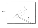
- the scene information acquisition unit 12 recognizes the arrangement of organs, blood vessels, and the like in the endoscopic image B, and dissects the peeling line L to be peeled off by the treatment tool 6. Recognize as.
- the scene information acquisition unit 12 may recognize the marking.
- the scene estimation unit 15 estimates the treatment scene based on the movement vector V and the anatomical information. Specifically, as shown in FIG. 14A, when the biological tissue is peeled off by the treatment tool 6, the operator moves the treatment tool 6 along the peeling line L, so that the movement direction of the treatment tool 6 is peeled off. It coincides with the longitudinal direction of the line L. When the direction of the movement vector V coincides with the longitudinal direction of the peeling line L, the scene estimation unit 15 estimates that the treatment scene is a peeling scene in which the biological tissue is peeled using the treatment tool 6.
- the treatment tool 6 when the treatment tool 6 is performing an operation other than peeling, for example, the treatment tool 6 is moved in a direction intersecting the peeling line L to develop a peeled portion. At this time, the moving direction of the treatment tool 6 does not coincide with the longitudinal direction of the peeling line L.
- the scene estimation unit 15 estimates that the treatment scene is a scene other than the peeling scene. Whether or not the direction of the movement vector V coincides with the longitudinal direction of the peeling line L is determined, for example, by whether or not the angle formed by the direction of the moving vector V and the direction of the peeling line L is equal to or less than a predetermined value. ..
- the offset parameter determination unit 13 determines the offset parameter based on the movement vector V and the treatment scene. Specifically, when the treatment scene is a peeling scene, the offset parameter determination unit 13 determines an offset parameter for arranging the region C in front of the treatment tool 6 in the center of the visual field F in the moving direction of the treatment tool 6. .. When the treatment scene is a scene other than the peeling scene, the offset parameter determination unit 13 determines the offset parameter for arranging the target point T at the reference point O.
- the control method executed by the control device 1 will be described.
- the processor 1a of the control device 1 automatically causes the endoscope 2 to follow the treatment tool 6 to be tracked by executing steps S2 to S18 shown in FIG.
- the scene information acquisition unit 12 acquires the movement vector V (step S4), and further acquires the anatomical information in the endoscopic image B (step S17).
- the scene estimation unit 15 estimates the treatment scene observed by the endoscope 2 based on the movement vector V and the anatomical information (step S9). Specifically, when the direction of the movement vector V coincides with the longitudinal direction of the peeling line L, the scene estimation unit 15 estimates that the treatment scene is a peeling scene. On the other hand, when the direction of the movement vector V does not match the longitudinal direction of the peeling line L, the scene estimation unit 15 estimates that the treatment scene is another scene.
- the offset parameter determination unit 13 determines the offset parameter based on the treatment scene and the movement vector V (steps S10, S12, S18). Specifically, in the case of a peeling scene (“peeling scene” in step S10), the offset parameter determining unit 13 calculates the offset parameter using the function F (V) for the peeling scene or the parameter table E (step). S12). As a result, the target point T is offset from the center of the visual field F in the direction opposite to the moving direction of the treatment tool 6 (step S7), and the tip 6a of the treatment tool 6 is opposite to the peeling direction from the center of the endoscope image B. The region C offset in the direction and peeled off by the treatment tool 6 is placed in the center of the endoscopic image B.
- the offset parameter determination unit 13 determines the offset parameter for arranging the target point T at the reference point O (step S18).
- the target point T is set at the center of the visual field F, and the tip 6a of the treatment tool 6 is arranged at the center of the endoscopic image B.
- the current treatment scene can be estimated based on the anatomical information in the endoscopic image B and the movement vector V representing the movement of the treatment tool 6. Then, by determining whether or not to offset the target point T from the reference point O based on the treatment scene, the tip 6a of the treatment tool 6 in the endoscopic image B is placed at a position suitable for the current treatment scene. Can be placed.
- the region C to be peeled off by the treatment tool 6 is arranged at the center of the endoscopic image B.
- the target point T is set as the reference point O
- the tip 6a of the treatment tool 6 is arranged at the center in the endoscopic image B. This allows the operator to easily observe the tip 6a of the treatment tool 6.
- the type of the treatment tool 6 of the second embodiment may be further used as the scene information.
- the treatment scene may be estimated based on the type of treatment tool 6.
- the type and operating state of the treatment tool 6 of the third embodiment may be further used as the scene information. For example, if the treatment scene is presumed to be another scene based on the movement vector and anatomical information, then the treatment scene may be presumed based on the type and operating state of the treatment tool 6.
- the present embodiment differs from the first to fourth embodiments in that the offset parameter is determined based on the input of the operator.
- configurations different from those of the first to fourth embodiments will be described, and configurations common to the first to fourth embodiments will be designated by the same reference numerals and description thereof will be omitted.
- the endoscope system 10 includes a control device 1, an endoscope 2, a moving device 3, an endoscope processor 4, and a display device 5. Similar to the first embodiment, the control device 1 includes a position information acquisition unit 11, a scene information acquisition unit 12, an offset parameter determination unit 13, and a control unit 14.
- the user interface 1d has any input device such as a mouse, keyboard or touch panel. The operator can input the position of the tip 6a of the treatment tool 6 to the control device 1 using the user interface 1d.
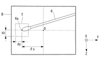
- offset angles ⁇ y and ⁇ z are input as the position of the tip 6a.
- the offset angle ⁇ y is the angle at which the line segment connecting the tip 2b of the endoscope 2 and the position of the tip 6a forms with the optical axis A in the XY plane
- the offset angle ⁇ z is the angle of the endoscope 2 in the XZ plane.
- the line segment connecting the positions of the tip 2b and the tip 6a is the angle formed with the optical axis A.
- the offset angle ⁇ y determines the distance ⁇ y in the Y direction from the reference point O to the position of the tip 6a at each position in the X direction.
- the offset angle ⁇ z determines the distance ⁇ z in the Z direction from the reference point O to the position of the tip 6a at each position in the X direction.
- the scene information acquisition unit 12 acquires the position of the tip 6a input by using the user interface 1d as the scene information.
- the offset parameter determination unit 13 determines the offset parameter based on the input position of the tip 6a. For example, the offset parameter determination unit 13 calculates the three-dimensional position (D, ⁇ y, ⁇ z) determined by the distance D and the offset angles ⁇ y, ⁇ z as the offset parameter.
- the control unit 14 sets the target point T at a three-dimensional position (D, ⁇ y, ⁇ z). Therefore, the position of the tip 6a input by the operator is set at the target point T.
- the control method executed by the control device 1 will be described.
- the processor 1a of the control device 1 automatically causes the endoscope 2 to follow the treatment tool 6 to be tracked by executing steps S1 to S20 shown in FIG.
- the endoscope 2 is placed on the tip 6a of the treatment tool 6 so that the tip 6a of the treatment tool 6 is arranged at the reference point O in the field of view F.
- the tip 2b of is followed.
- the scene information acquisition unit 12 acquires the position input by the operator (step S20), and the offset parameter determination unit 13 The offset parameter is determined based on the input position (step S6), and the control unit 14 sets the target point T at the position input by the operator (step S7).
- the tip 6a of the treatment tool 6 in the endoscopic image B moves from the center to the target point T at the position designated by the operator.
- the target point T is offset to the input position by the input of the position of the tip 6a of the treatment tool 6 by the operator as a trigger.
- the operator can set the target point T at an arbitrary position suitable for the current treatment scene at an arbitrary timing, and move the tip 6a in the endoscopic image B to an arbitrary position at an arbitrary timing. It can be offset.
- the scene information acquisition unit 12 acquires the position of the tip 6a of the treatment tool 6 as scene information when an input instructing the start of adjustment of the target point T is performed. May be good.
- the operator moves the tip 6a of the treatment tool 6 to a desired position in the endoscope image B, and inputs an instruction to start adjustment to the control device 1 using the user interface 1d (step S21). ..
- the scene information acquisition unit 12 acquires the position of the tip 6a at the time when the instruction is input (step S22).
- the scene information acquisition unit 12 stores the endoscope image B at the time when the instruction is input, and sets the three-dimensional position of the tip 6a of the treatment tool 6 with respect to the tip 2b of the endoscope 2 as the endoscope image B. Calculated from.
- the operator inputs an instruction to end the adjustment of the target point T (YES in step S23)
- the adjustment of the target point T is completed and the target point T returns to the reference point O (step S1).
- the scene information acquisition unit 12 acquires the position of the tip 6a of the treatment tool 6 as scene information, but instead, acquires the position and posture of the endoscope 2 as scene information. You may.
- the scene information acquisition unit 12 acquires information on the current position and posture of the endoscope 2 from the moving device 3.
- 18A to 19B show examples of the position and orientation of the endoscope 2.
- the position and posture of the endoscope 2 differ depending on the treatment target site and the treatment content, that is, the treatment scene.
- the endoscope 2 is inserted into the abdominal cavity via the hole H formed in the body wall, and the position and posture of the endoscope 2 are changed with the position of the hole H as a fulcrum.
- the position and orientation of the endoscope 2 is, for example, a position and orientation in a coordinate system fixed with respect to the subject P with respect to the fulcrum.
- a plurality of offset parameters according to the position and posture of the endoscope 2 are preset or set by an operator such as an operator during the operation.
- the offset parameter determination unit 13 selects an offset parameter corresponding to the position and orientation of the endoscope 2. Therefore, as shown in FIGS. 18B and 19B, the target point T is set at a position corresponding to the position and posture of the endoscope 2. According to this configuration, scene information can be acquired without requiring an input operation by an operator.
- the target point T is offset in the three-dimensional direction with respect to the reference point O, but instead, the target point T is offset in the two-dimensional direction or the one-dimensional direction with respect to the reference point O. It may be offset.
- the scene information acquisition unit 12 detects a two-dimensional movement vector V along the YZ plane perpendicular to the optical axis A, and the offset parameter determination unit 13 determines the target point T with respect to the reference point O. May be determined in a two-dimensional offset parameter for offsetting in a direction parallel to the YZ plane.
- the scene information acquisition unit 12 detects the one-dimensional movement vector V in the Z direction parallel to the optical axis A, and the offset parameter determination unit 13 sets the target point T with respect to the reference point O.
- One-dimensional offset parameters for offsetting only in the direction may be determined.
- the reference point O is a point on the optical axis A of the visual field F, but the reference point can be set at an arbitrary position in the visual field F and is a point outside the optical axis A. It may be.
- the target point T is one point in the visual field F, but instead, it may be a two-dimensional or three-dimensional region. In this case, the control device 1 may start following the endoscope 2 with respect to the treatment tool 6 when the tip 6a of the treatment tool 6 comes out of the region of the target point T.
- the target point T is a rectangular parallelepiped region having predetermined dimensions dx, dy, dz in the X, Y and Z directions.
- the region centered on the three-dimensional position calculated from the movement vector V is set at the target point T.
- the area centered on the position input by the operator is set as the target point T.
- the position information acquisition unit 11 has decided to acquire the position information from the endoscope image B, but instead of this, the position information may be acquired by using another means.
- the position information acquisition unit 11 may acquire position information from a three-dimensional position measuring device arranged outside the body.
- the three-dimensional position measuring device measures the position of the first marker attached to the endoscope 2 and the position of the second marker attached to the treatment tool 6, and performs endoscopy from the two measured positions.
- the three-dimensional position of the tip 6a of the treatment tool 6 with respect to the tip 2b of the mirror 2 may be calculated.
- the position information acquisition unit 11 may acquire position information from a three-dimensional scanning device attached to the endoscope 2.
- the three-dimensional scanning device may measure the three-dimensional positions of the treatment tool 6 and the biological tissue in the field view F of the endoscope 2 by scanning light or ultrasonic waves.
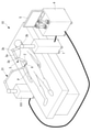
- the position information acquisition unit 11 is transferred from the first moving device 3 for moving the endoscope 2 and the second moving device 31 for moving the treatment tool 6.
- Information on the positions of the endoscope 2 and the treatment tool 6 may be acquired, respectively.
- the second moving device 31 holds the treatment tool 6 by a robot arm or an electric holder, and changes the position and posture of the treatment tool 6 three-dimensionally according to the control by the control device 101.
- the treatment tool 6 may be connected to the tip of the robot arm and integrated with the robot arm, and as shown in FIG. 21B, the treatment tool 6 is separate from the robot arm and is gripped by the robot arm. It may have been done.
- the position information acquisition unit 11 has decided to acquire the position information including the three-dimensional position of the treatment tool 6, but instead, the position information including the two-dimensional position of the treatment tool 6 is acquired.
- the treatment tool 6, the target point T, and the reference point O are two-dimensional positions on the image plane (YZ plane) of the endoscope image B, and the control unit 14 sets the target point T with respect to the reference point O.
- the endoscope 2 may be made to follow the treatment tool 6 two-dimensionally in the Y direction and the Z direction while being two-dimensionally offset in the Y direction and the Z direction.
- Control device 2 Endoscope 3 Moving device 6 Treatment tool 6a Tip 10 Endoscope system A Optical axis B Endoscope image F Field L Detachment line (anatomical information) T Target point O Reference point P Patient, subject V Movement vector (scene information)
Landscapes
- Health & Medical Sciences (AREA)
- Life Sciences & Earth Sciences (AREA)
- Engineering & Computer Science (AREA)
- Surgery (AREA)
- Physics & Mathematics (AREA)
- Public Health (AREA)
- Animal Behavior & Ethology (AREA)
- General Health & Medical Sciences (AREA)
- Heart & Thoracic Surgery (AREA)
- Veterinary Medicine (AREA)
- Molecular Biology (AREA)
- Medical Informatics (AREA)
- Biomedical Technology (AREA)
- Nuclear Medicine, Radiotherapy & Molecular Imaging (AREA)
- Pathology (AREA)
- Biophysics (AREA)
- Optics & Photonics (AREA)
- Radiology & Medical Imaging (AREA)
- Signal Processing (AREA)
- General Physics & Mathematics (AREA)
- Robotics (AREA)
- Human Computer Interaction (AREA)
- Multimedia (AREA)
- Theoretical Computer Science (AREA)
- Computer Vision & Pattern Recognition (AREA)
- Mechanical Engineering (AREA)
- Astronomy & Astrophysics (AREA)
- Endoscopes (AREA)
- Instruments For Viewing The Inside Of Hollow Bodies (AREA)
Abstract
Description
本出願は、2020年9月10日にアメリカ合衆国に仮出願された米国特許仮出願第63/076,408号の優先権を主張し、その内容をここに援用する。
本発明の第1実施形態に係る制御装置、内視鏡システムおよび制御方法について図面を参照して説明する。
図1に示されるように、本実施形態に係る内視鏡システム10は、内視鏡2および1以上の処置具6を被検体である患者Pの体内に挿入し、処置具6を内視鏡2によって観察しながら処置具6で処置対象部位を処置する手術に使用され、例えば、腹腔鏡下手術に使用される。
メモリ1bは、例えば、ROM(read-only memory)、または、RAM(Random Access Memory)領域を含む半導体メモリである。メモリ1bも、後述する記憶部1cと同様に、プロセッサ1aの処理に必要なデータを記憶してもよい(すなわち、「記憶部」として動作してもよい。)。
マニュアルモードは、操作者が内視鏡2を手動で操作するモードである。マニュアルモードにおいて、例えば、操作者は、制御装置1に接続された操作装置(図示略)を操作することによって、ロボットアーム3aまたは電動ホルダを遠隔操作することができる。
追従モードは、制御装置1が移動装置3を制御することによって内視鏡2を追従対象に設定された処置具6に自動的に追従させるモードである。
図3Aおよび図3Bにおいて、内視鏡2の光軸Aに平行な方向がX方向であり、光軸Aに直交し内視鏡画像Bの横方向に対応する方向がY方向であり、光軸Aに直交し内視鏡画像Bの縦方向に対応する方向がZ方向である。
V=P1-P2
P1は、時刻tにおける内視鏡画像B内の先端6aの3次元の位置ベクトル(x1,y1,z1)であり、P2は、時刻tからΔt後の時刻t+Δtにおける内視鏡画像B内の先端6aの3次元の位置ベクトル(x2,y2,z2)である。内視鏡画像Bは、内視鏡2から直接または内視鏡プロセッサ4を経由して、制御装置1に入力される。
具体的には、図6Aおよび図6Bに示されるように、オフセットパラメータ決定部13は、移動ベクトルVの向きに基づいて、処置具6の移動方向において該処置具6の前方の領域Cを視野Fの中心に(すなわち、光軸A上に)配置するオフセットパラメータを決定する。図6Aおよび図6Bにおいて、矢印は処置具6の移動方向を表している。
例えば、図4Bに示されるように、F(V)=-k*Vであり、kは係数である。この場合、移動ベクトルVが大きい程、3次元ベクトルF(V)は大きくなり、基準点Oに対する目標点Tのオフセット距離が大きくなる。
また、制御部14は、位置情報取得部11から処置具6の先端6aの3次元位置の情報を受け取る。
追従モードに切り替わると、制御装置1のプロセッサ1aは、図7に示されるステップS1~S7を実行することによって、処置具6に内視鏡2を自動的に追従させる。
追従モードの開始時、制御部14は、目標点Tを、内視鏡2の視野Fの中心である基準点Oに初期設定する(ステップS1)。
次に、制御部14は、先端6aが目標点Tに配置されるように処置具6の先端6aに内視鏡2の先端2bを追従させる(ステップS3)。具体的には、制御部14は、先端6aおよび目標点Tの3次元位置に基づいて移動装置3を制御し、視野F内の目標点Tが先端6aの位置に配置されるように内視鏡2を移動させる。
まず、シーン情報取得部12が、処置具6の移動ベクトルVを取得する(ステップS4)。
移動ベクトルの大きさ|V|が閾値αよりも大きい場合(ステップS5のNO)、ステップS6およびS7の処理は実行されず、制御部14は、目標点Tを基準点Oに維持する(ステップS1)。したがって、先端6aが内視鏡画像B内の中心に配置されるように、内視鏡2が処置具6に追従する。
特に、移動ベクトルの大きさ|V|が閾値α以下になる剥離シーンの場合、先端6aが処置具6の移動方向とは逆方向に基準点Oからオフセットした位置に配置され、処置具6の移動方向の前方の領域C、すなわちこれから剥離される領域が、内視鏡画像Bの中心に配置される。したがって、術者は、剥離される領域Cを容易に観察することができる。
図9は、パラメータテーブルEを使用する場合の制御方法を示している。図9に示されるように、ステップS5が省略され、|V|に関わらず、オフセットパラメータの決定が繰り返される。
次に、本発明の第2実施形態に係る制御装置、内視鏡システムおよびの制御方法について説明する。
本実施形態は、移動ベクトルVと処置具6の種類とに基づいてオフセットパラメータを決定する点において、第1実施形態と相違する。本実施形態において、第1実施形態と異なる構成について説明し、第1実施形態と共通する構成については同一の符号を付して説明を省略する。
図10に示されるように、制御装置1は、位置情報取得部11、シーン情報取得部12、オフセットパラメータ決定部13および制御部14に加えて、シーン推定部15をさらに備える。シーン推定部15の機能は、他の部11,12,13,14と同様、プロセッサ1aによって実現される。
具体的には、処置シーンが剥離シーンである場合、図6Aおよび図6Bに示されるように、オフセットパラメータ決定部13は、処置具6によって剥離される領域C、すなわち処置具6の移動方向において該処置具6の前方の領域Cを視野Fの中心に配置するオフセットパラメータを決定する。
処置シーンが展開シーンである場合、図11に示されるように、オフセットパラメータ決定部13は、処置具6によって展開される領域C、すなわち処置具6の移動方向において該処置具6の後方の領域Cを視野Fの中心に配置するオフセットパラメータを決定する。
追従モードに切り替わると、制御装置1のプロセッサ1aは、図12に示されるステップS2~S12を実行することによって、追従対象である処置具6に内視鏡2を自動的に追従させる。
本実施形態において、シーン情報取得部12は、移動ベクトルVを取得し(ステップS4)、さらに、処置具6の種類を取得する(ステップS8)。
次に、シーン推定部15が、処置具6の種類に基づいて、内視鏡2によって観察されている処置シーンを推定する(ステップS9)。
具体的には、展開シーンである場合(ステップS10の「展開シーン」)、オフセットパラメータ決定部13は、展開シーン用の関数F(V)またはパラメータテーブルEを用いてオフセットパラメータを算出する(ステップS11)。これにより、図11に示されるように、目標点Tが視野Fの中心の基準点Oから処置具6の移動方向と同一方向にオフセットし、処置具6の先端6aが内視鏡画像Bの中心から展開方向と同一方向にオフセットし、処置具6によって展開される領域Cが内視鏡画像Bの中心に配置される。
具体的には、展開シーンのときには、処置具6によって展開された領域Cが内視鏡画像Bの中心に配置されるので、術者は、展開された領域Cを容易に観察することができる。剥離シーンのときには、処置具6によってこれから剥離される領域Cが内視鏡画像Bの中心に配置されるので、術者は、これから剥離される領域Cを容易に観察することができる。
例えば、シーン情報取得部12は、既知の画像認識技術によって内視鏡画像B内の被検体の解剖学的特徴を認識し、当該解剖学的特徴の種類や、位置および向きなどの情報をシーン情報として取得し、シーン推定部15は、当該シーン情報に基づいて処置シーンを推定してもよい。
あるいは、シーン情報取得部12は、既知の画像認識技術によって内視鏡画像B内の被検体の出血の発生といったシーンの変化を検知し、検知した情報をシーン情報として取得し、シーン推定部15は、当該シーン情報に基づいて処置シーンを推定してもよい。
さらに、シーンの推定は上記の実施態様に限られるものではなく、シーン情報取得部12は、手術中に得られるいかなる情報をシーン情報として取得することができ、シーン推定部15は当該シーン情報に基づいて処置シーンを推定してもよい。
次に、本発明の第3実施形態に係る制御装置、内視鏡システムおよび制御方法について説明する。
本実施形態は、移動ベクトルVと処置具6の種類および作動状態とに基づいてオフセットパラメータを決定する点において、第1および第2実施形態と相違する。本実施形態において、第1および第2実施形態と異なる構成について説明し、第1および第2実施形態と共通する構成については同一の符号を付して説明を省略する。
制御装置1は、第2実施形態と同様、位置情報取得部11、シーン情報取得部12、オフセットパラメータ決定部13、制御部14およびシーン推定部15を備える。
例えば、第2実施形態と同様に、処置シーン毎に関数F(V)またはパラメータテーブルEが予め用意され記憶部1cに記憶されている。すなわち、展開シーン用の関数F(V)またはパラメータテーブルEと、剥離シーン(アクティブ)用の関数F(V)またはパラメータテーブルEと、剥離シーン(非アクティブ)用の関数F(V)またはパラメータテーブルEとが用意されている。オフセットパラメータ決定部13は、シーン推定部15によって推定された処置シーン用の関数F(V)またはパラメータテーブルEを選択し、選択した関数F(V)またはパラメータテーブルEを用いて、3次元ベクトルをオフセットパラメータとして算出する。
追従モードに切り替わると、制御装置1のプロセッサ1aは、図13に示されるステップS2~S16を実行することによって、追従対象である処置具6に内視鏡2を自動的に追従させる。
本実施形態において、シーン情報取得部12は、移動ベクトルVを取得し(ステップS4)、処置具6の種類を取得し(ステップS8)、さらに、処置具6の作動状態を取得する(ステップS13)。
具体的には、展開シーンである場合(ステップS10の「展開シーン」)、第3実施形態と同様に、オフセットパラメータ決定部13は、展開シーン用の関数F(V)またはパラメータテーブルEを用いてオフセットパラメータを算出する(ステップS11)。
剥離シーンの内、処置具6が非アクティブ中のシーンである場合(ステップS14のNO)、オフセットパラメータ決定部13は、剥離シーン(非アクティブ)用の関数F(V)またはパラメータテーブルEを用いてオフセットパラメータを算出する(ステップS16)。
本実施形態によれば、処置具6の種類および作動状態づいてさらに詳細な現在の処置シーンを推定することができ、内視鏡画像B内の処置具6の先端6aを現在の処置シーンにさらに適した位置に配置することができる。
次に、本発明の第4実施形態に係る制御装置、内視鏡システムおよび制御方法について説明する。
本実施形態は、移動ベクトルVと生体組織の解剖情報とに基づいてオフセットパラメータを決定する点において、第1から第3実施形態と相違する。本実施形態において、第1から第3実施形態と異なる構成について説明し、第1から第3実施形態と共通する構成については同一の符号を付して説明を省略する。
制御装置1は、第2実施形態と同様、位置情報取得部11、シーン情報取得部12、オフセットパラメータ決定部13、制御部14およびシーン推定部15を備える。
具体的には、図14Aに示されるように、処置具6によって生体組織を剥離するとき、術者は、処置具6を剥離ラインLに沿って移動させるので、処置具6の移動方向は剥離ラインLの長手方向と一致する。移動ベクトルVの方向が剥離ラインLの長手方向と一致する場合、シーン推定部15は、処置シーンが、処置具6を使用して生体組織を剥離する剥離シーンであると推定する。
移動ベクトルVの方向が剥離ラインLの長手方向と一致するか否かは、例えば、移動ベクトルVの方向と剥離ラインLの方向とが成す角度が所定値以下であるか否かによって判断される。
具体的には、処置シーンが剥離シーンである場合、オフセットパラメータ決定部13は、処置具6の移動方向において該処置具6の前方の領域Cを視野Fの中心に配置するオフセットパラメータを決定する。
処置シーンが剥離シーン以外のシーンである場合、オフセットパラメータ決定部13は、目標点Tを基準点Oに配置するオフセットパラメータを決定する。
追従モードに切り替わると、制御装置1のプロセッサ1aは、図15に示されるステップS2~S18を実行することによって、追従対象である処置具6に内視鏡2を自動的に追従させる。
本実施形態において、シーン情報取得部12は、移動ベクトルVを取得し(ステップS4)、さらに、内視鏡画像B内の解剖情報を取得する(ステップS17)。
具体的には、剥離シーンである場合(ステップS10の「剥離シーン」)、オフセットパラメータ決定部13は、剥離シーン用の関数F(V)またはパラメータテーブルEを用いてオフセットパラメータを算出する(ステップS12)。これにより、目標点Tが視野Fの中心から処置具6の移動方向とは逆方向にオフセットし(ステップS7)、処置具6の先端6aが内視鏡画像Bの中心から剥離方向とは逆方向にオフセットし、処置具6によって剥離される領域Cが内視鏡画像Bの中心に配置される。
一方、他のシーンである場合(ステップS10の「他のシーン」)、オフセットパラメータ決定部13は、目標点Tを基準点Oに配置するオフセットパラメータを決定する(ステップS18)。これにより、目標点Tが視野Fの中心に設定され、処置具6の先端6aが内視鏡画像Bの中心に配置される。
剥離シーン以外の他のシーンのときには、目標点Tが基準点Oに設定され、処置具6の先端6aが内視鏡画像B内の中心に配置される。これにより、術者は、処置具6の先端6aを容易に観察することができる。
また、本実施形態において、シーン情報として、第3実施形態の処置具6の種類および作動状態をさらに使用してもよい。例えば、処置シーンが移動ベクトルおよび解剖情報に基づいて他のシーンであると推定された場合、続いて、処置具6の種類および作動状態に基づいて処置シーンが推定されてもよい。
次に、本発明の第5実施形態に係る制御装置、内視鏡システムおよび制御方法について説明する。
本実施形態は、操作者の入力に基づいてオフセットパラメータを決定する点において、第1から第4実施形態と相違する。本実施形態において、第1から第4実施形態と異なる構成について説明し、第1から第4実施形態と共通する構成については同一の符号を付して説明を省略する。
制御装置1は、第1実施形態と同様、位置情報取得部11、シーン情報取得部12、オフセットパラメータ決定部13および制御部14を備える。
ユーザインタフェース1dは、マウス、キーボードまたはタッチパネル等の任意の入力デバイスを有する。操作者は、処置具6の先端6aの位置をユーザインタフェース1dを使用して制御装置1に入力することができる。
オフセットパラメータ決定部13は、入力された先端6aの位置に基づいてオフセットパラメータを決定する。例えば、オフセットパラメータ決定部13は、距離Dとオフセット角φy,φzとによって決定される3次元位置(D,δy,δz)をオフセットパラメータとして算出する。
制御部14は、目標点Tを3次元位置(D,δy,δz)に設定する。したがって、操作者が入力した先端6aの位置が目標点Tに設定される。
追従モードに切り替わると、制御装置1のプロセッサ1aは、図16に示されるステップS1~S20を実行することによって、追従対象である処置具6に内視鏡2を自動的に追従させる。
操作者は、処置シーンに応じて先端6aの位置を内視鏡画像B内の中心から他の位置へ移動させたいとき、所望の先端6aの位置をユーザインタフェース1dを使用して制御装置1に入力する。
この場合、操作者は、内視鏡画像B内の所望の位置へ処置具6の先端6aを移動させ、調整開始の指示をユーザインタフェース1dを使用して制御装置1に入力する(ステップS21)。入力に応答し、シーン情報取得部12は、指示が入力された時点での先端6aの位置を取得する(ステップS22)。例えば、シーン情報取得部12は、指示が入力された時点での内視鏡画像Bを記憶し、内視鏡2の先端2bに対する処置具6の先端6aの3次元位置を内視鏡画像Bから算出する。
目標点Tの調整終了の指示が操作者によって入力されると(ステップS23のYES)、目標点Tの調整が終了し、目標点Tが基準点Oに戻る(ステップS1)。
図18Aから図19Bは、内視鏡2の位置および姿勢の例を示している。腹腔鏡下手術において、処置対象部位および処置の内容に応じて、すなわち処置シーンに応じて、内視鏡2の位置および姿勢は異なる。
図18Aおよび図19Aにおいて、内視鏡2は体壁に形成された穴Hを経由して腹腔内に挿入され、穴Hの位置を支点として内視鏡2の位置および姿勢が変更される。内視鏡2の位置および姿勢は、例えば、支点を基準とし被検体Pに対して固定された座標系での位置および姿勢である。
この構成によれば、操作者による入力操作を必要とすることなく、シーン情報を取得することができる。
例えば、一変形例において、シーン情報取得部12が、光軸Aに垂直なYZ平面に沿う2次元の移動ベクトルVを検出し、オフセットパラメータ決定部13が、基準点Oに対して目標点TをYZ平面に平行な方向にオフセットさせるための2次元的なオフセットパラメータを決定してもよい。他の変形例において、シーン情報取得部12が、光軸Aに平行なZ方向における1次元の移動ベクトルVを検出し、オフセットパラメータ決定部13が、基準点Oに対して目標点TをX方向にのみオフセットさせるための1次元的なオフセットパラメータを決定してもよい。
上記各実施形態において、目標点Tが、視野F内の一点であることとしたが、これに代えて、2次元または3次元の領域であってもよい。この場合、制御装置1は、処置具6の先端6aが目標点Tの領域の外側に出たときに、処置具6に対する内視鏡2の追従を開始してもよい。
一変形例において、位置情報取得部11は、体外に配置される3次元位置測定装置から位置情報を取得してもよい。例えば、3次元位置測定装置は、内視鏡2に取り付けられた第1マーカの位置と、処置具6に取り付けられた第2マーカの位置とを測定し、測定された2つの位置から内視鏡2の先端2bに対する処置具6の先端6aの3次元位置を算出してもよい。
例えば、処置具6、目標点Tおよび基準点Oが、内視鏡画像Bの画像平面(YZ平面)上における2次元位置であり、制御部14が、目標点Tを基準点Oに対してY方向およびZ方向に2次元的にオフセットさせるとともに、処置具6に対して内視鏡2をY方向およびZ方向に2次元的に追従させてもよい。
2 内視鏡
3 移動装置
6 処置具
6a 先端
10 内視鏡システム
A 光軸
B 内視鏡画像
F 視野
L 剥離ライン(解剖情報)
T 目標点
O 基準点
P 患者、被検体
V 移動ベクトル(シーン情報)
Claims (16)
- 内視鏡の移動を制御し該内視鏡を処置具に追従させる制御装置であって、
プロセッサを備え、
該プロセッサが、
前記処置具の位置を含む位置情報を取得し、
シーン情報を取得し、該シーン情報は前記内視鏡によって観察される処置シーンと関連する情報であり、
前記シーン情報に基づいて目標点のオフセットパラメータを決定し、該オフセットパラメータは、前記内視鏡の視野内の所定の基準点に対する前記目標点の位置を決定するパラメータであり、
該オフセットパラメータに基づいて前記基準点に対する前記目標点の位置を設定し、
前記目標点の位置および前記処置具の前記位置に基づいて前記内視鏡の移動を制御することによって、前記処置具が前記目標点に配置されるように前記内視鏡を前記処置具に追従させる、制御装置。 - 前記プロセッサが、
前記シーン情報として前記処置具の移動ベクトルを取得し、
該移動ベクトルに基づいて前記オフセットパラメータを決定する、請求項1に記載の制御装置。 - 前記プロセッサが、前記移動ベクトルの方向に基づいて、前記処置具の移動方向において該処置具の前方の領域を前記視野の中心に配置する前記オフセットパラメータを決定する、請求項2に記載の制御装置。
- 前記プロセッサが、
前記シーン情報に基づいて前記処置シーンを推定し、
推定された前記処置シーンに基づいて前記オフセットパラメータを決定する、請求項1に記載の制御装置。 - 前記プロセッサが、
前記シーン情報として前記処置具の種類を取得し、
該処置具の種類に基づいて前記処置シーンを推定する、請求項4に記載の制御装置。 - 前記処置シーンが剥離シーンであると推定された場合、
前記プロセッサが、前記処置具によって剥離される領域を前記視野の中心に配置する前記オフセットパラメータを決定する、請求項5に記載の制御装置。 - 前記処置シーンが展開シーンであると推定された場合、
前記プロセッサが、前記処置具によって展開される領域を前記視野の中心に配置する前記オフセットパラメータを設定する、請求項5に記載の制御装置。 - 前記プロセッサが、
前記シーン情報として前記処置具の作動状態を取得し、
該処置具の作動状態に基づいて前記処置シーンを推定する、請求項4に記載の制御装置。 - 前記プロセッサが、
前記シーン情報として前記視野内の生体組織の解剖情報を取得し、
該解剖情報に基づいて前記処置シーンを推定する、請求項4に記載の制御装置。 - 前記プロセッサが、前記処置具の3次元位置を含む前記位置情報を取得する、請求項1に記載の制御装置。
- 内視鏡の移動を制御し処置具に前記内視鏡を追従させる制御装置であって、
プロセッサを備え、
該プロセッサが、
被検体内の画像から位置情報を取得し、
前記画像から処置シーンを推定し、
該処置シーンに基づいて、前記内視鏡の視野における処置具の位置を決定する、制御装置。 - 内視鏡と、
該内視鏡を被検体内で移動させる移動装置と、
該移動装置を制御し前記内視鏡を処置具に追従させる請求項1から請求項11のいずれかに記載の制御装置と、を備える内視鏡システム。 - 前記内視鏡が、前記被検体内を撮像し前記被検体内の画像を取得する請求項12に記載の内視鏡システム。
- 前記移動装置が、前記内視鏡と接続され該内視鏡の位置および姿勢を制御するロボットアームを備える、請求項12に記載の内視鏡システム。
- 前記プロセッサは、
前記目標点が前記処置具の先端に配置される前記内視鏡の位置および姿勢を算出し、
算出された前記内視鏡の位置および姿勢に基づいて前記ロボットアームを制御する請求項14に記載の内視鏡システム。 - 内視鏡の移動を制御し該内視鏡を処置具に追従させる制御方法であって、
前記処置具の位置を含む位置情報を取得する工程と、
シーン情報を取得し、該シーン情報は前記内視鏡によって観察される処置シーンと関連する情報である、工程と、
該シーン情報に基づいて目標点のオフセットパラメータを決定し、該オフセットパラメータは、前記内視鏡の視野内の所定の基準点に対する前記目標点の位置を決定するパラメータである、工程と、
該オフセットパラメータに基づいて前記基準点に対する前記目標点の位置を設定する工程と、
前記目標点の位置および前記処置具の前記位置に基づいて前記内視鏡の移動を制御することによって、前記処置具が前記目標点に配置されるように前記内視鏡を前記処置具に追従させる工程と、を含む、制御方法。
Priority Applications (3)
| Application Number | Priority Date | Filing Date | Title |
|---|---|---|---|
| CN202180053634.1A CN115996662B (zh) | 2020-09-10 | 2021-09-09 | 控制装置、内窥镜系统、存储介质以及程序产品 |
| JP2022547657A JP7522840B2 (ja) | 2020-09-10 | 2021-09-09 | 制御装置 |
| US18/105,305 US20230172675A1 (en) | 2020-09-10 | 2023-02-03 | Controller, endoscope system, and control method |
Applications Claiming Priority (2)
| Application Number | Priority Date | Filing Date | Title |
|---|---|---|---|
| US202063076408P | 2020-09-10 | 2020-09-10 | |
| US63/076,408 | 2020-09-10 |
Related Child Applications (1)
| Application Number | Title | Priority Date | Filing Date |
|---|---|---|---|
| US18/105,305 Continuation US20230172675A1 (en) | 2020-09-10 | 2023-02-03 | Controller, endoscope system, and control method |
Publications (1)
| Publication Number | Publication Date |
|---|---|
| WO2022054882A1 true WO2022054882A1 (ja) | 2022-03-17 |
Family
ID=80629721
Family Applications (4)
| Application Number | Title | Priority Date | Filing Date |
|---|---|---|---|
| PCT/JP2021/027564 Ceased WO2022054428A1 (ja) | 2020-09-10 | 2021-07-26 | 医療システムおよび制御方法 |
| PCT/JP2021/033210 Ceased WO2022054884A1 (ja) | 2020-09-10 | 2021-09-09 | 内視鏡システム、制御装置、制御方法および記録媒体 |
| PCT/JP2021/033209 Ceased WO2022054883A1 (ja) | 2020-09-10 | 2021-09-09 | 制御装置、内視鏡システム、制御方法および制御プログラム |
| PCT/JP2021/033205 Ceased WO2022054882A1 (ja) | 2020-09-10 | 2021-09-09 | 制御装置、内視鏡システムおよび制御方法 |
Family Applications Before (3)
| Application Number | Title | Priority Date | Filing Date |
|---|---|---|---|
| PCT/JP2021/027564 Ceased WO2022054428A1 (ja) | 2020-09-10 | 2021-07-26 | 医療システムおよび制御方法 |
| PCT/JP2021/033210 Ceased WO2022054884A1 (ja) | 2020-09-10 | 2021-09-09 | 内視鏡システム、制御装置、制御方法および記録媒体 |
| PCT/JP2021/033209 Ceased WO2022054883A1 (ja) | 2020-09-10 | 2021-09-09 | 制御装置、内視鏡システム、制御方法および制御プログラム |
Country Status (4)
| Country | Link |
|---|---|
| US (4) | US20230180996A1 (ja) |
| JP (3) | JP7535587B2 (ja) |
| CN (3) | CN116171122A (ja) |
| WO (4) | WO2022054428A1 (ja) |
Cited By (1)
| Publication number | Priority date | Publication date | Assignee | Title |
|---|---|---|---|---|
| WO2024009901A1 (ja) * | 2022-07-08 | 2024-01-11 | オリンパス株式会社 | 内視鏡システム、制御方法および制御プログラム |
Families Citing this family (11)
| Publication number | Priority date | Publication date | Assignee | Title |
|---|---|---|---|---|
| US9204939B2 (en) * | 2011-08-21 | 2015-12-08 | M.S.T. Medical Surgery Technologies Ltd. | Device and method for assisting laparoscopic surgery—rule based approach |
| EP3337419B1 (en) * | 2015-08-19 | 2020-08-12 | Brainlab AG | Reference array holder |
| TWI782409B (zh) * | 2020-03-09 | 2022-11-01 | 陳階曉 | 內視鏡影像校正系統及其方法 |
| DE112021008246T5 (de) * | 2021-11-30 | 2024-07-04 | Olympus Corporation | Endoskopsystem und koordinatensystemkorrekturverfahren |
| US20230255442A1 (en) * | 2022-02-11 | 2023-08-17 | Canon U.S.A., Inc. | Continuum robot apparatuses, methods, and storage mediums |
| WO2023195326A1 (ja) * | 2022-04-05 | 2023-10-12 | オリンパス株式会社 | 内視鏡システム、手技支援方法および手技支援プログラム |
| CN115956859B (zh) * | 2022-10-11 | 2026-04-14 | 中国医学科学院北京协和医院 | 内窥镜控制方法及手术机器人系统 |
| WO2024157360A1 (ja) * | 2023-01-24 | 2024-08-02 | 国立研究開発法人国立がん研究センター | 内視鏡画像の処置具検出装置、内視鏡画像の処置具検出方法、及び内視鏡画像の処置具検出装置プログラム |
| US20240349985A1 (en) * | 2023-04-24 | 2024-10-24 | Karl Storz Se & Co. Kg | Corrective adjustment of image parameters using artificial intelligence |
| CN117481753B (zh) * | 2023-12-29 | 2024-04-05 | 北京智愈医疗科技有限公司 | 一种基于内窥镜的水刀运动轨迹的监测方法和装置 |
| WO2025163471A1 (en) * | 2024-01-29 | 2025-08-07 | Covidien Lp | Hysteroscopic surgical systems for use with surgical robotic systems and surgical robotic systems incorporating the same |
Citations (4)
| Publication number | Priority date | Publication date | Assignee | Title |
|---|---|---|---|---|
| JP2007301378A (ja) * | 2006-05-11 | 2007-11-22 | Olympus Medical Systems Corp | 治療システム及びトラカール並びに治療システムの制御方法 |
| WO2018179681A1 (ja) * | 2017-03-28 | 2018-10-04 | ソニー・オリンパスメディカルソリューションズ株式会社 | 医療用観察装置及び観察視野補正方法 |
| WO2018235255A1 (ja) * | 2017-06-23 | 2018-12-27 | オリンパス株式会社 | 医療システムとその作動方法 |
| WO2019116592A1 (ja) * | 2017-12-14 | 2019-06-20 | オリンパス株式会社 | 内視鏡の表示画像の調整装置及び手術システム |
Family Cites Families (51)
| Publication number | Priority date | Publication date | Assignee | Title |
|---|---|---|---|---|
| JP2911894B2 (ja) * | 1986-11-13 | 1999-06-23 | オリンパス光学工業株式会社 | 内視鏡画像取込み方法および内視鏡装置 |
| JP2797830B2 (ja) * | 1992-03-31 | 1998-09-17 | 日本ビクター株式会社 | ビデオカメラにおける被写体追尾方法 |
| JP3348933B2 (ja) * | 1993-03-19 | 2002-11-20 | オリンパス光学工業株式会社 | 電子式内視鏡装置 |
| JP2833425B2 (ja) * | 1993-06-30 | 1998-12-09 | 日本ビクター株式会社 | ビデオカメラにおける被写体追尾装置 |
| JP3419869B2 (ja) * | 1993-12-28 | 2003-06-23 | オリンパス光学工業株式会社 | 医療器具 |
| JPH0938030A (ja) * | 1995-07-28 | 1997-02-10 | Shimadzu Corp | 内視鏡装置 |
| JPH09266882A (ja) * | 1996-04-02 | 1997-10-14 | Olympus Optical Co Ltd | 内視鏡装置 |
| JP3889873B2 (ja) * | 1998-02-24 | 2007-03-07 | オリンパス株式会社 | 計測内視鏡装置 |
| US7037258B2 (en) * | 1999-09-24 | 2006-05-02 | Karl Storz Imaging, Inc. | Image orientation for endoscopic video displays |
| JP2001112704A (ja) * | 1999-10-20 | 2001-04-24 | Olympus Optical Co Ltd | 内視鏡システム |
| JP2003088532A (ja) * | 2001-09-19 | 2003-03-25 | Olympus Optical Co Ltd | 手術装置 |
| JP4331541B2 (ja) * | 2003-08-06 | 2009-09-16 | オリンパス株式会社 | 内視鏡装置 |
| US20050123179A1 (en) * | 2003-12-05 | 2005-06-09 | Eastman Kodak Company | Method and system for automatic axial rotation correction in vivo images |
| US7654997B2 (en) * | 2004-04-21 | 2010-02-02 | Acclarent, Inc. | Devices, systems and methods for diagnosing and treating sinusitus and other disorders of the ears, nose and/or throat |
| JP4377745B2 (ja) * | 2004-05-14 | 2009-12-02 | オリンパス株式会社 | 電子内視鏡 |
| JP4699040B2 (ja) * | 2005-02-15 | 2011-06-08 | パナソニック株式会社 | 自動追尾制御装置及び自動追尾制御方法、並びにプログラム、自動追尾システム |
| JP4785127B2 (ja) * | 2005-12-08 | 2011-10-05 | 学校法人早稲田大学 | 内視鏡視野拡張システム、内視鏡視野拡張装置及び内視鏡視野拡張用プログラム |
| JP4980625B2 (ja) * | 2006-02-21 | 2012-07-18 | 富士フイルム株式会社 | 体腔内観察装置 |
| US20080108870A1 (en) * | 2006-11-06 | 2008-05-08 | Wiita Bruce E | Apparatus and method for stabilizing an image from an endoscopic camera |
| JP5030639B2 (ja) * | 2007-03-29 | 2012-09-19 | オリンパスメディカルシステムズ株式会社 | 内視鏡装置の処置具位置制御装置 |
| US8083669B2 (en) * | 2007-06-22 | 2011-12-27 | Olympus Medical Systems Corp. | Medical device for maintaining state of treatment portion |
| JP5192898B2 (ja) * | 2008-04-25 | 2013-05-08 | オリンパスメディカルシステムズ株式会社 | マニピュレータシステム |
| JP2010220794A (ja) * | 2009-03-24 | 2010-10-07 | Fujifilm Corp | 内視鏡画像回転装置および方法並びにプログラム |
| US9439556B2 (en) * | 2010-12-10 | 2016-09-13 | Wayne State University | Intelligent autonomous camera control for robotics with medical, military, and space applications |
| JPWO2012108085A1 (ja) * | 2011-02-08 | 2014-07-03 | オリンパスメディカルシステムズ株式会社 | 医療機器 |
| JP6021369B2 (ja) * | 2012-03-21 | 2016-11-09 | Hoya株式会社 | 内視鏡システム |
| TWI517828B (zh) * | 2012-06-27 | 2016-01-21 | 國立交通大學 | 影像追蹤系統及其影像追蹤方法 |
| CN105142494B (zh) * | 2013-07-12 | 2017-09-29 | 奥林巴斯株式会社 | 内窥镜系统 |
| JP6218634B2 (ja) * | 2014-02-20 | 2017-10-25 | オリンパス株式会社 | 内視鏡システム及び内視鏡の作動方法 |
| JP6257371B2 (ja) * | 2014-02-21 | 2018-01-10 | オリンパス株式会社 | 内視鏡システム及び内視鏡システムの作動方法 |
| KR102387096B1 (ko) * | 2014-03-28 | 2022-04-15 | 인튜어티브 서지컬 오퍼레이션즈 인코포레이티드 | 시계 내의 기기들의 정량적 3차원 시각화 |
| JP2017518147A (ja) * | 2014-03-28 | 2017-07-06 | インテュイティブ サージカル オペレーションズ, インコーポレイテッド | 手術シーンの定量的三次元撮像 |
| WO2017014308A1 (ja) * | 2015-07-23 | 2017-01-26 | オリンパス株式会社 | マニピュレータ及び医療システム |
| WO2017082047A1 (ja) * | 2015-11-13 | 2017-05-18 | オリンパス株式会社 | 内視鏡システム |
| WO2017130567A1 (ja) * | 2016-01-25 | 2017-08-03 | ソニー株式会社 | 医療用安全制御装置、医療用安全制御方法、及び医療用支援システム |
| WO2017138208A1 (ja) * | 2016-02-10 | 2017-08-17 | オリンパス株式会社 | 内視鏡システム |
| JP6177485B1 (ja) * | 2016-02-10 | 2017-08-09 | オリンパス株式会社 | マニピュレータシステム |
| CN107456278B (zh) * | 2016-06-06 | 2021-03-05 | 北京理工大学 | 一种内窥镜手术导航方法和系统 |
| JP2019165270A (ja) * | 2016-08-03 | 2019-09-26 | シャープ株式会社 | 映像出力システム、映像出力方法および制御装置 |
| WO2018051565A1 (ja) * | 2016-09-15 | 2018-03-22 | オリンパス株式会社 | 超音波内視鏡および超音波内視鏡システム |
| CN110325093B (zh) * | 2017-02-28 | 2022-04-08 | 索尼公司 | 医疗用臂系统、控制装置与控制方法 |
| WO2019035206A1 (ja) * | 2017-08-18 | 2019-02-21 | オリンパス株式会社 | 医療システムおよび画像生成方法 |
| DE102017219621B4 (de) * | 2017-09-22 | 2025-11-13 | Carl Zeiss Meditec Ag | Visualisierungssystem mit einem Beobachtungsgerät und einem Endoskop |
| US12262866B2 (en) * | 2017-09-22 | 2025-04-01 | Carl Zeiss Meditec Ag | Visualization system comprising an observation apparatus and an endoscope |
| JP7151109B2 (ja) * | 2018-03-19 | 2022-10-12 | ソニーグループ株式会社 | 医療用撮像装置及び医療用観察システム |
| WO2020070883A1 (ja) * | 2018-10-05 | 2020-04-09 | オリンパス株式会社 | 内視鏡システム |
| US20200273552A1 (en) * | 2019-02-21 | 2020-08-27 | Theator inc. | System for Detecting an Omitted Event During a Surgical Procedure |
| JP2020151044A (ja) * | 2019-03-18 | 2020-09-24 | ソニー・オリンパスメディカルソリューションズ株式会社 | 医療用観察装置 |
| JP7480477B2 (ja) * | 2019-07-10 | 2024-05-10 | ソニーグループ株式会社 | 医療用観察システム、制御装置及び制御方法 |
| EP4021335B1 (en) * | 2019-08-30 | 2025-01-29 | Brainlab AG | Image based motion control correction |
| JP2021040987A (ja) * | 2019-09-12 | 2021-03-18 | ソニー株式会社 | 医療用支持アーム、及び医療用システム |
-
2021
- 2021-07-26 JP JP2022547429A patent/JP7535587B2/ja active Active
- 2021-07-26 WO PCT/JP2021/027564 patent/WO2022054428A1/ja not_active Ceased
- 2021-07-26 CN CN202180053633.7A patent/CN116171122A/zh active Pending
- 2021-09-09 CN CN202180053602.1A patent/CN116018538A/zh active Pending
- 2021-09-09 JP JP2022547657A patent/JP7522840B2/ja active Active
- 2021-09-09 WO PCT/JP2021/033210 patent/WO2022054884A1/ja not_active Ceased
- 2021-09-09 WO PCT/JP2021/033209 patent/WO2022054883A1/ja not_active Ceased
- 2021-09-09 CN CN202180053634.1A patent/CN115996662B/zh active Active
- 2021-09-09 JP JP2022547659A patent/JP7534423B2/ja active Active
- 2021-09-09 WO PCT/JP2021/033205 patent/WO2022054882A1/ja not_active Ceased
-
2023
- 2023-02-03 US US18/105,314 patent/US20230180996A1/en active Pending
- 2023-02-03 US US18/105,300 patent/US20230180998A1/en active Pending
- 2023-02-03 US US18/105,305 patent/US20230172675A1/en active Pending
- 2023-02-03 US US18/105,291 patent/US20230180995A1/en not_active Abandoned
Patent Citations (4)
| Publication number | Priority date | Publication date | Assignee | Title |
|---|---|---|---|---|
| JP2007301378A (ja) * | 2006-05-11 | 2007-11-22 | Olympus Medical Systems Corp | 治療システム及びトラカール並びに治療システムの制御方法 |
| WO2018179681A1 (ja) * | 2017-03-28 | 2018-10-04 | ソニー・オリンパスメディカルソリューションズ株式会社 | 医療用観察装置及び観察視野補正方法 |
| WO2018235255A1 (ja) * | 2017-06-23 | 2018-12-27 | オリンパス株式会社 | 医療システムとその作動方法 |
| WO2019116592A1 (ja) * | 2017-12-14 | 2019-06-20 | オリンパス株式会社 | 内視鏡の表示画像の調整装置及び手術システム |
Cited By (1)
| Publication number | Priority date | Publication date | Assignee | Title |
|---|---|---|---|---|
| WO2024009901A1 (ja) * | 2022-07-08 | 2024-01-11 | オリンパス株式会社 | 内視鏡システム、制御方法および制御プログラム |
Also Published As
| Publication number | Publication date |
|---|---|
| CN115996662B (zh) | 2025-11-18 |
| US20230180995A1 (en) | 2023-06-15 |
| CN116018538A (zh) | 2023-04-25 |
| US20230180998A1 (en) | 2023-06-15 |
| JP7522840B2 (ja) | 2024-07-25 |
| US20230180996A1 (en) | 2023-06-15 |
| WO2022054428A1 (ja) | 2022-03-17 |
| JPWO2022054882A1 (ja) | 2022-03-17 |
| WO2022054883A1 (ja) | 2022-03-17 |
| JP7535587B2 (ja) | 2024-08-16 |
| JP7534423B2 (ja) | 2024-08-14 |
| US20230172675A1 (en) | 2023-06-08 |
| CN116171122A (zh) | 2023-05-26 |
| JPWO2022054884A1 (ja) | 2022-03-17 |
| JPWO2022054428A1 (ja) | 2022-03-17 |
| WO2022054884A1 (ja) | 2022-03-17 |
| CN115996662A (zh) | 2023-04-21 |
Similar Documents
| Publication | Publication Date | Title |
|---|---|---|
| WO2022054882A1 (ja) | 制御装置、内視鏡システムおよび制御方法 | |
| JP7802047B2 (ja) | ロボット操作手術器具の位置を追跡システムおよび方法 | |
| Zhang et al. | Autonomous scanning for endomicroscopic mosaicing and 3D fusion | |
| US12349860B2 (en) | Medical observation system, control device, and control method | |
| US9615890B2 (en) | Surgical robot system and method of controlling the same | |
| US20210015343A1 (en) | Surgical assistance apparatus, surgical method, non-transitory computer readable medium and surgical assistance system | |
| CN110099599B (zh) | 医学图像处理设备、医学图像处理方法和程序 | |
| WO2018179749A1 (en) | Surgical imaging system, image processing apparatus for surgery, and method for controlling an imaging procedure | |
| WO2020054566A1 (ja) | 医療用観察システム、医療用観察装置及び医療用観察方法 | |
| JP7334499B2 (ja) | 手術支援システム、制御装置及び制御方法 | |
| WO2020086912A1 (en) | Mixed reality systems and methods for indicating an extent of a field of view of an imaging device | |
| JP2023507063A (ja) | 手術中に画像取込装置を制御するための方法、装置、およびシステム | |
| CN115517615B (zh) | 内窥镜主从运动控制方法及手术机器人系统 | |
| JP2004041778A (ja) | 体腔内観察システム | |
| WO2018173681A1 (ja) | 医療用システムの制御装置、医療用システムの制御方法及び医療用システム | |
| US20140241577A1 (en) | Method of tracking moving object, method of determining display state of moving object, and control apparatus for tracking moving object | |
| Wu et al. | Model-free image guidance for intelligent tubular robots with pre-clinical feasibility study: Towards minimally invasive trans-orifice surgery | |
| US12383126B2 (en) | Surgery system and control method for surgery system to adjust position and orientation of imager | |
| US20250268454A1 (en) | Surgical assistance system and surgical assistance device | |
| US12094061B2 (en) | System and methods for updating an anatomical 3D model | |
| WO2019035206A1 (ja) | 医療システムおよび画像生成方法 | |
| JP7674528B2 (ja) | 内視鏡システム、内視鏡システムの制御方法および記録媒体 | |
| JP7854499B2 (ja) | 内視鏡システム、内視鏡システムの作動方法および手技支援プログラム | |
| CN121694803A (zh) | 超声波探头的操作辅助系统、记录介质及计算机程序产品 | |
| WO2022219878A1 (ja) | 医療用観察システム、医療用画像処理方法及び情報処理装置 |
Legal Events
| Date | Code | Title | Description |
|---|---|---|---|
| 121 | Ep: the epo has been informed by wipo that ep was designated in this application |
Ref document number: 21866839 Country of ref document: EP Kind code of ref document: A1 |
|
| ENP | Entry into the national phase |
Ref document number: 2022547657 Country of ref document: JP Kind code of ref document: A |
|
| WWE | Wipo information: entry into national phase |
Ref document number: 202180053634.1 Country of ref document: CN |
|
| NENP | Non-entry into the national phase |
Ref country code: DE |
|
| 122 | Ep: pct application non-entry in european phase |
Ref document number: 21866839 Country of ref document: EP Kind code of ref document: A1 |