WO2022044643A1 - ヘッドレスト用の給電構造 - Google Patents
ヘッドレスト用の給電構造 Download PDFInfo
- Publication number
- WO2022044643A1 WO2022044643A1 PCT/JP2021/027455 JP2021027455W WO2022044643A1 WO 2022044643 A1 WO2022044643 A1 WO 2022044643A1 JP 2021027455 W JP2021027455 W JP 2021027455W WO 2022044643 A1 WO2022044643 A1 WO 2022044643A1
- Authority
- WO
- WIPO (PCT)
- Prior art keywords
- headrest
- power
- holder
- feeding
- coil
- Prior art date
- Legal status (The legal status is an assumption and is not a legal conclusion. Google has not performed a legal analysis and makes no representation as to the accuracy of the status listed.)
- Ceased
Links
Images




Classifications
-
- B—PERFORMING OPERATIONS; TRANSPORTING
- B60—VEHICLES IN GENERAL
- B60R—VEHICLES, VEHICLE FITTINGS, OR VEHICLE PARTS, NOT OTHERWISE PROVIDED FOR
- B60R16/00—Electric or fluid circuits specially adapted for vehicles and not otherwise provided for; Arrangement of elements of electric or fluid circuits specially adapted for vehicles and not otherwise provided for
- B60R16/02—Electric or fluid circuits specially adapted for vehicles and not otherwise provided for; Arrangement of elements of electric or fluid circuits specially adapted for vehicles and not otherwise provided for electric constitutive elements
- B60R16/03—Electric or fluid circuits specially adapted for vehicles and not otherwise provided for; Arrangement of elements of electric or fluid circuits specially adapted for vehicles and not otherwise provided for electric constitutive elements for supply of electrical power to vehicle subsystems or for
-
- A—HUMAN NECESSITIES
- A47—FURNITURE; DOMESTIC ARTICLES OR APPLIANCES; COFFEE MILLS; SPICE MILLS; SUCTION CLEANERS IN GENERAL
- A47C—CHAIRS; SOFAS; BEDS
- A47C7/00—Parts, details, or accessories of chairs or stools
- A47C7/36—Supports for the head or the back
- A47C7/38—Supports for the head or the back for the head, e.g. detachable
-
- B—PERFORMING OPERATIONS; TRANSPORTING
- B60—VEHICLES IN GENERAL
- B60N—SEATS SPECIALLY ADAPTED FOR VEHICLES; VEHICLE PASSENGER ACCOMMODATION NOT OTHERWISE PROVIDED FOR
- B60N2/00—Seats specially adapted for vehicles; Arrangement or mounting of seats in vehicles
- B60N2/02—Seats specially adapted for vehicles; Arrangement or mounting of seats in vehicles the seat or part thereof being movable, e.g. adjustable
- B60N2/0224—Non-manual adjustments, e.g. with electrical operation
- B60N2/0244—Non-manual adjustments, e.g. with electrical operation with logic circuits
- B60N2/0264—Non-manual adjustments, e.g. with electrical operation with logic circuits characterised by the type of electrical connection, e.g. wiring, plugs or USB
-
- B—PERFORMING OPERATIONS; TRANSPORTING
- B60—VEHICLES IN GENERAL
- B60N—SEATS SPECIALLY ADAPTED FOR VEHICLES; VEHICLE PASSENGER ACCOMMODATION NOT OTHERWISE PROVIDED FOR
- B60N2/00—Seats specially adapted for vehicles; Arrangement or mounting of seats in vehicles
- B60N2/80—Head-rests
- B60N2/806—Head-rests movable or adjustable
- B60N2/809—Head-rests movable or adjustable vertically slidable
-
- B—PERFORMING OPERATIONS; TRANSPORTING
- B60—VEHICLES IN GENERAL
- B60N—SEATS SPECIALLY ADAPTED FOR VEHICLES; VEHICLE PASSENGER ACCOMMODATION NOT OTHERWISE PROVIDED FOR
- B60N2/00—Seats specially adapted for vehicles; Arrangement or mounting of seats in vehicles
- B60N2/80—Head-rests
- B60N2/806—Head-rests movable or adjustable
- B60N2/809—Head-rests movable or adjustable vertically slidable
- B60N2/829—Head-rests movable or adjustable vertically slidable characterised by their adjusting mechanisms, e.g. electric motors
-
- B—PERFORMING OPERATIONS; TRANSPORTING
- B60—VEHICLES IN GENERAL
- B60N—SEATS SPECIALLY ADAPTED FOR VEHICLES; VEHICLE PASSENGER ACCOMMODATION NOT OTHERWISE PROVIDED FOR
- B60N2/00—Seats specially adapted for vehicles; Arrangement or mounting of seats in vehicles
- B60N2/80—Head-rests
- B60N2/879—Head-rests with additional features not related to head-rest positioning, e.g. heating or cooling devices or loudspeakers
-
- B—PERFORMING OPERATIONS; TRANSPORTING
- B60—VEHICLES IN GENERAL
- B60N—SEATS SPECIALLY ADAPTED FOR VEHICLES; VEHICLE PASSENGER ACCOMMODATION NOT OTHERWISE PROVIDED FOR
- B60N2/00—Seats specially adapted for vehicles; Arrangement or mounting of seats in vehicles
- B60N2/80—Head-rests
- B60N2/897—Head-rests with sleeves located in the back-rest for guiding the rods of the head-rest
-
- B—PERFORMING OPERATIONS; TRANSPORTING
- B60—VEHICLES IN GENERAL
- B60R—VEHICLES, VEHICLE FITTINGS, OR VEHICLE PARTS, NOT OTHERWISE PROVIDED FOR
- B60R16/00—Electric or fluid circuits specially adapted for vehicles and not otherwise provided for; Arrangement of elements of electric or fluid circuits specially adapted for vehicles and not otherwise provided for
- B60R16/02—Electric or fluid circuits specially adapted for vehicles and not otherwise provided for; Arrangement of elements of electric or fluid circuits specially adapted for vehicles and not otherwise provided for electric constitutive elements
- B60R16/037—Electric or fluid circuits specially adapted for vehicles and not otherwise provided for; Arrangement of elements of electric or fluid circuits specially adapted for vehicles and not otherwise provided for electric constitutive elements for occupant comfort, e.g. for automatic adjustment of appliances according to personal settings, e.g. seats, mirrors, steering wheel
-
- H—ELECTRICITY
- H02—GENERATION; CONVERSION OR DISTRIBUTION OF ELECTRIC POWER
- H02J—ELECTRIC POWER NETWORKS; CIRCUIT ARRANGEMENTS OR SYSTEMS FOR SUPPLYING OR DISTRIBUTING ELECTRIC POWER; SYSTEMS FOR STORING ELECTRIC ENERGY
- H02J50/00—Circuit arrangements or systems for wireless supply or distribution of electric power
- H02J50/10—Circuit arrangements or systems for wireless supply or distribution of electric power using inductive coupling
Definitions
- This disclosure relates to a power supply structure for headrests.
- the headrest is attached to the upper surface of the seat back for the purpose of protecting the occupant's head in the event of a vehicle collision. Some headrests can be adjusted in height as needed.
- Japanese Patent Application Laid-Open No. 7-241221 discloses a headrest whose height can be adjusted with a simple structure.
- the headrest is fixed by the engagement between the snap spring provided on the holder on the seat back side and the locking groove provided on the stay extending from the headrest.
- the headrest becomes movable.
- the locking grooves are provided at several positions at predetermined intervals, and the operator can adjust the height of the headrest by appropriately selecting the locking grooves and engaging them with the snap springs.
- the operator can easily attach / detach the headrest by inserting the stay into the holder or pulling out the stay from the holder while keeping the snap spring in the disengaged state.
- a connector for electrically connecting the circuit on the electric device side and the circuit on the seat back side may be provided.
- the operator has to disconnect and disconnect the connector in addition to the conventional attachment / detachment work each time the headrest is attached / detached. Therefore, it has been desired to simplify the work of electrically connecting to the headrest.
- the present disclosure has been completed based on the above circumstances, and an object thereof is to provide a power supply structure for a headrest in which electrical connection work is simplified.
- the present disclosure is a power supply structure for a headrest for supplying power to a headrest attached to a seat body, and the power supply coil arranged on the seat body and the power supply coil arranged on the headrest. It includes a power receiving coil that receives the power, and an elastic member that is arranged on at least one of the seat body and the headrest and urges the power feeding coil and the power receiving coil in a direction to approach each other.
- the electrical connection work can be simplified in the power supply structure for the headrest.
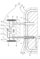
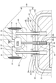
- FIG. 1 is a partially enlarged schematic cross-sectional view showing a power feeding structure for a headrest attached to the seat device according to the first embodiment.
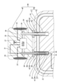
- FIG. 2 is a partially enlarged schematic cross-sectional view showing a feeding structure for a headrest attached to a seat device in a state where the headrest is arranged above the state shown in FIG.
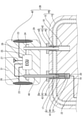
- FIG. 3 is a partially enlarged schematic cross-sectional view showing a power feeding structure for a headrest attached to the seat device according to the second embodiment.
- FIG. 4 is a partially enlarged schematic cross-sectional view showing a feeding structure for a headrest attached to a seat device in a state where the headrest is arranged above the state shown in FIG.
- FIG. 1 is a partially enlarged schematic cross-sectional view showing a power feeding structure for a headrest attached to the seat device according to the first embodiment.
- FIG. 2 is a partially enlarged schematic cross-sectional view showing a feeding structure for a headrest attached to a seat device in a state
- FIG. 5 is a partially enlarged schematic cross-sectional view showing a power feeding structure for a headrest attached to the seat device according to the third embodiment.
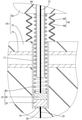
- FIG. 6 is a partially enlarged schematic cross-sectional view showing a feeding structure for a headrest.
- FIG. 7 is a partially enlarged schematic cross-sectional view showing a feeding structure for a headrest attached to a seat device in a state where the headrest is arranged above the state shown in FIG.
- FIG. 8 is a partially enlarged schematic cross-sectional view showing a power feeding structure for a headrest attached to the seat device according to the fourth embodiment.
- FIG. 9 is a partially enlarged schematic cross-sectional view showing a feeding structure for a headrest attached to a seat device in a state where the headrest is arranged above the state shown in FIG.
- the present disclosure is a power supply structure for a headrest for supplying power to a headrest attached to the seat body, and the power supply coil arranged on the seat body and the power supply coil arranged on the headrest. It includes a power receiving coil that receives power from the seat body, and an elastic member that is arranged on at least one of the seat body and the headrest and urges the feeding coil and the power receiving coil in a direction of approaching each other.
- the seat body and headrest can be electrically connected by a simple configuration.
- the electrical connection work between the seat body and the headrest can be simplified.
- the seat body has a tubular headrest holder extending toward the headrest, and the headrest has a tubular shape extending toward the seat body and is internally or externally fitted to the headrest holder. It is preferable that the headrest stay is provided, the feeding coil is arranged in the headrest holder, and the power receiving coil is arranged in the headrest stay.
- the headrest can be assembled by fitting the headrest stay and the headrest holder to the seat body.
- the headrest holder has a support portion that supports the elastic member from below, the power feeding coil is arranged above the elastic member, and the power receiving coil is located near the lower end of the headrest stay. It is preferably fixed.
- the elastic member can be held in the headrest stay by a simple configuration.
- a headrest cap having an insertion hole through which the headrest stay is inserted is attached to the upper end of the headrest holder, and the elastic member is arranged between the headrest cap and the feeding coil. It is preferable to have.
- the elastic member is preferably arranged between the lower end of the headrest and the feeding coil.
- the elastic member can be attached to the feeding structure without increasing the number of parts.
- the seat body has a tubular headrest holder extending toward the headrest and a feeding holder different from the headrest holder, and the feeding holder has a tubular shape extending toward the headrest.
- the headrest has a tubular shape extending toward the seat body, and has a headrest stay that is internally or externally fitted to the headrest holder, and a power supply stay that is different from the headrest stay.
- the power supply stay is fitted inside or outside the power supply holder, the power supply coil is arranged in the power supply holder, and the power receiving coil is arranged in the power supply stay. Is preferable.
- the headrest stay is surrounded by a cover that surrounds the headrest stay and that can be expanded and contracted in the vertical direction.
- the power supply structure for the headrest can be protected by a cover.
- a shield member having conductivity is arranged on the inner surface of the cover.
- the power supply structure for the headrest can prevent electromagnetic waves from leaking to the outside.
- the power feeding structure 11 for the headrest 10 is attached to, for example, a seat device 12A mounted on a vehicle (not shown) such as an automobile.
- the seat device 12A includes a seat body 13 and a headrest 10.
- the front-rear, left-right directions refer to the directions viewed from the occupant seated on the seat device 12A.
- the seat device 12A includes a seat body 13 and a headrest 10 attached to an upper end portion of the seat body 13.
- the seat body 13 includes a metal seat skeleton 14 and a cushion 15 attached to the seat skeleton 14.
- the cushion 15 is made of, for example, a polyurethane foam and receives the weight of the occupant when the occupant sits on the seat body 13.
- a power feeding headrest holder 17 (an example of the headrest holder according to the present embodiment) in which a feeding coil 16 is arranged and a headrest holder 18 are formed side by side on the upper portion of the seat skeleton 14 at intervals in the left-right direction. ing.
- the power feeding headrest holder 17 and the headrest holder 18 are made of metal and are formed in a cylindrical shape extending in the vertical direction.
- the cross-sectional shape of the power feeding headrest holder 17 and the headrest holder 18 may be a circular shape or an oval shape, or may be a polygonal shape such as a triangular shape or a square shape.
- the positions of the upper ends of the power feeding headrest holder 17 and the headrest holder 18 are not particularly limited, and may be arranged below the upper surface of the cushion 15 arranged at the upper end of the seat body 13, or the cushion 15 may be arranged. It may be arranged at the same height as the upper surface of the cushion 15, or may be arranged at a position above the upper surface of the cushion 15. In the present embodiment, the positions of the upper ends of the power feeding headrest holder 17 and the headrest holder 18 are arranged at the same height as the upper surface of the cushion 15.
- a bottom wall 19 (an example of a support portion) is formed at the lower end of the power supply headrest holder 17.
- the bottom wall 19 is formed with a through hole 20 that penetrates in the vertical direction.
- An elastic member 21 is placed on the upper surface of the bottom wall 19.
- the elastic member 21 is formed so as to be elastically deformable in the vertical direction.
- a spring having an arbitrary shape such as a spiral spring, a leaf spring, a bamboo shoot spring, or the like can be adopted.
- the elastic member 21 may be made of metal, or may be made of synthetic resin such as natural rubber or synthetic rubber.
- the elastic member 21 according to the present embodiment is a metal spiral spring.
- the inner diameter of the elastic member 21 is formed to be larger than the diameter of the through hole 20.
- the outer diameter dimension of the elastic member 21 is formed to be slightly smaller than the inner diameter dimension of the power feeding headrest holder 17. As a result, the elastic member 21 is held in a state of being placed on the upper surface of the bottom wall 19.
- a feeding coil 16 is arranged at the upper end of the elastic member 21.
- the upper end portion of the elastic member 21 and the lower end portion of the feeding coil 16 may or may not be fixed.
- the outer diameter of the feeding coil 16 is formed to be slightly larger than the outer diameter of the elastic member 21.
- the outer diameter of the feeding coil 16 is the same as or slightly smaller than the inner diameter of the feeding headrest holder 17.
- the feeding coil 16 is arranged so as to be movable in the vertical direction inside the feeding headrest holder 17 by sliding contact with the inner wall of the feeding headrest holder 17.
- the seat side electric wire 22 is connected to the power feeding coil 16.
- the seat-side electric wire 22 extends downward from the feeding coil 16 through the inside of the elastic member 21.
- the seat-side electric wire 22 is routed inside the seat body 13 through a through hole 20 formed in the bottom wall 19 of the power feeding headrest holder 17, and is connected to a power source (not shown).
- An electric device such as a speaker 23 is attached to the headrest 10.
- the electric device attached to the headrest 10 is not limited to the speaker 23, and any electric device such as a monitor, a heater, and a fan can be selected.
- a metal headrest skeleton 24 is arranged inside the headrest 10.
- the headrest skeleton 24 is formed so as to extend in the left-right direction.
- An ECU 25 Electric Control Unit
- the ECU 25 is connected to the speaker 23 by a speaker electric wire 26.
- the ECU 25 has an antenna 27.
- the ECU 25 outputs an audio signal to the speaker 23 based on the signal received via the antenna 27. Based on this signal, the speaker 23 is designed to output sound.
- a headrest stay 28 for power supply (an example of the headrest stay of the present invention) and a headrest stay 29 are arranged side by side with an interval in the left-right direction.
- the power feeding headrest stay 28 and the headrest stay 29 are made of metal and are formed in a cylindrical shape extending in the vertical direction.
- the outer diameter of the headrest stay 29 is smaller than the inner diameter of the headrest holder 18. As a result, the headrest stay 29 is fitted into the headrest holder 18.
- the outer diameter dimension of the power feeding headrest stay 28 is formed to be smaller than the inner diameter dimension of the power feeding headrest holder 17. As a result, the power supply headrest stay 28 is fitted inside the power supply headrest holder 17.
- a power receiving coil 30 is fixed to the lower end of the power feeding headrest holder 17.
- the power feeding headrest holder 17 and the power receiving coil 30 are fixed by screwing, bonding, a known lock structure, or the like.
- the headrest side electric wire 31 is connected to the power receiving coil 30.
- the headrest side electric wire 31 extends upward from the power receiving coil 30 and is arranged.
- the headrest side electric wire 31 passes through the inside of the power feeding headrest holder 17 and is led out from the upper end portion of the power feeding headrest holder 17.
- the headrest side electric wire 31 is connected to the ECU 25. As a result, the electric power supplied from the power source is supplied to the speaker 23 via the seat side electric wire 22, the power feeding coil 16, the power receiving coil 30, the headrest side electric wire 31, and the ECU 25.
- the power supply headrest stay 28 and the power supply headrest holder 17 are fixed at predetermined height positions in the vertical direction by a known support member (not shown).
- the headrest stay 29 and the headrest holder 18 are fixed at predetermined height positions in the vertical direction by a known support member (not shown).
- the power feeding structure 11 includes a power feeding coil 16, a power receiving coil 30, and an elastic member 21.
- the power feeding coil 16 and the power receiving coil 30 are formed by spirally winding an electric wire around a core made of a magnetic material such as ferrite or a synthetic resin.
- a magnetic wire for example, a copper wire coated with an insulating layer such as enamel can be used.
- the outer diameter dimension of the power feeding coil 16 is formed to be larger than the outer diameter dimension of the power receiving coil 30.
- the outer diameter of the power feeding coil 16 and the outer diameter of the power receiving coil 30 are not particularly limited, and the outer diameter of the feeding coil 16 may be smaller than the outer diameter of the power receiving coil 30.
- the power receiving coil 30 is placed on the upper surface of the power feeding coil 16.
- the power receiving coil 30 is not fixed to the feeding coil 16. Therefore, the power receiving coil 30 and the feeding coil 16 can be separated from each other.
- the power receiving coil 30 is arranged at a position coaxial with the feeding coil 16.
- the method of supplying electric power from the feeding coil 16 to the receiving coil 30 may be an electromagnetic induction method or a magnetic field resonance method.
- the elastic member 21 arranged below the power feeding coil 16 urges the feeding coil 16 in the direction (upward) approaching the power receiving coil 30. As a result, even when the power receiving coil 30 moves upward and moves away from the power feeding coil 16, the power feeding coil 16 is urged upward by the elastic member 21, so that the power feeding coil 16 comes into contact with the power receiving coil 30. It is designed to do.
- the electromagnetic waves generated from the power feeding coil 16 and the power receiving coil 30 can be electromagnetically shielded.
- FIG. 1 shows a configuration in which the headrest 10 is fixed at the lowermost position with respect to the seat body 13. In this state, the lower end of the headrest 10 is in contact with the upper end of the seat body 13.
- FIG. 2 shows a configuration in which the headrest 10 is fixed at the uppermost position with respect to the seat body 13. In this state, the headrest 10 and the seat body 13 are separated in the vertical direction.
- the power receiving coil 30 attached to the lower end of the power feeding headrest stay 28 also moves upward. Then, since the feeding coil 16 is urged upward by the elastic member 21, it moves upward following the power receiving coil 30. As a result, even when the headrest 10 moves upward, the power feeding coil 16 and the power receiving coil 30 come into contact with each other. As a result, it is possible to suppress a decrease in the feeding efficiency from the feeding coil 16 to the power receiving coil 30.
- the power supply structure 11 for the headrest 10 is a power supply structure 11 for the headrest 10 for supplying power to the headrest 10 attached to the seat body 13, and is a power supply coil arranged in the seat body 13. 16, a power receiving coil 30 arranged on the headrest 10 to receive power from the feeding coil 16, an elastic member 21 arranged on the seat body 13 and urging the feeding coil 16 in a direction to approach the power receiving coil 30. To prepare for.
- the seat body 13 and the headrest 10 can be electrically connected by a simple configuration.
- the electrical connection work between the seat body 13 and the headrest 10 can be simplified.
- the elastic member 21 urges the feeding coil 16 in the direction of approaching the power receiving coil 30, the feeding coil 16 can follow the power receiving coil 30 even when the headrest 10 moves in the vertical direction with respect to the seat body 13. , The state in which the power feeding coil 16 and the power receiving coil 30 are in contact with each other can be maintained. As a result, it is possible to suppress a decrease in the efficiency of supplying electric power from the feeding coil 16 to the receiving coil 30.
- the seat body 13 has a power feeding headrest holder 17 having a tubular shape extending toward the headrest 10, and the headrest 10 has a tubular shape extending toward the seat body 13 and is used for power feeding. It has a power feeding headrest stay 28 fitted in the headrest holder 17, a power feeding coil 16 is arranged in the power feeding headrest holder 17, and a power receiving coil 30 is arranged in the power feeding headrest stay 28.
- the headrest 10 can be assembled to the seat body 13 by fitting the headrest stay 29 and the headrest holder 18.
- the power receiving coil 30 with one of the headrest stays 29 as the power supply headrest stay 28
- assembling the power supply coil 16 with one of the headrest holders 18 as the power supply headrest holder 17 the number of parts can be increased.
- the power feeding structure 11 can be assembled to the seat device 12 while suppressing the restraint.
- the power feeding headrest holder 17 has a bottom wall 19 that supports the elastic member 21 from below, the power feeding coil 16 is arranged above the elastic member 21, and the power receiving coil 30 feeds power.
- the headrest stay 28 is fixed at a position near the lower end.
- the elastic member 21 can be held in the power feeding headrest stay 28 by a simple configuration.
- a headrest cap 42 is attached to the upper end portion of the power feeding headrest holder 17, and a headrest cap 42 is attached to the upper end portion of the headrest holder 18.
- the headrest cap 42 attached to the power feeding headrest holder 17 and the headrest cap 42 attached to the headrest holder 18 have the same shape and size.
- the headrest cap 42 has a power feeding headrest holder 17, a shaft portion 43 that is internally fitted in the headrest holder 18 and extends in the vertical direction, and a lid portion 44 formed at the upper end portion of the shaft portion 43.
- the headrest cap 42 is made of synthetic resin.
- the headrest cap 42 has an insertion hole 45 penetrating in the vertical direction.
- a headrest stay 48 for power supply and a headrest holder 18 are inserted into the insertion holes 45 of the headrest cap 42, respectively.
- the shaft portion 43 has a cylindrical shape.
- the outer shape of the shaft portion 43 is formed substantially the same as the inner shape of the power feeding headrest holder 17, and is formed substantially the same as the inner shape of the headrest holder 18.
- the length dimension of the shaft portion 43 is formed to be shorter than the vertical length dimension of the power feeding headrest holder 17 and the headrest holder 18.
- the diameter of the lid portion 44 is larger than that of the outer shape of the shaft portion 43.
- the shape of the lid portion 44 can be any shape such as a circular shape or a quadrangular shape when viewed from above.
- the feeding coil 16 is mounted on the upper surface of the bottom wall 19 of the feeding headrest holder 17.
- a power receiving coil 46 is placed on the upper surface of the power feeding coil 16.
- the outer diameter dimension of the power feeding coil 16 is formed to be substantially the same as the outer diameter dimension of the power receiving coil 46.
- the outer diameter dimension of the power feeding coil 16 and the outer diameter dimension of the power receiving coil 46 are formed to be the same as or slightly smaller than the inner diameter dimension of the power feeding headrest holder 17.
- An elastic member 47 is arranged on the upper surface of the power receiving coil 46.
- the elastic member 47 is a spiral spring.
- the elastic member 47 is arranged in the gap between the power feeding headrest holder 17 and the power feeding headrest stay 28.
- the lower end of the elastic member 47 is in contact with the upper surface of the feeding coil 16 from above.
- the upper end portion of the elastic member 47 is in contact with the lower end portion of the shaft portion 43 of the headrest cap 42 from below. As a result, the power receiving coil 46 is urged in the direction (downward) approaching the feeding coil 16.
- the lower end of the power feeding headrest stay 48 and the power receiving coil 46 are not fixed.
- FIG. 3 shows a configuration in which the headrest 40 is fixed at the lowermost position with respect to the seat body 49. In this state, the lower end of the headrest 40 is in contact with the upper end of the headrest cap 42.
- the lower end of the power feeding headrest stay 48 comes into contact with the upper surface of the power receiving coil 46 and presses the power receiving coil 46 downward. Further, the elastic member 47 arranged between the lower end portion of the headrest cap 42 and the power receiving coil 46 urges the power receiving coil 46 downward by its elastic force. As a result, the power feeding coil 16 and the power receiving coil 46 come into contact with each other.
- FIG. 4 shows a configuration in which the headrest 40 is fixed at the uppermost position with respect to the seat body 49. In this state, the headrest 40 is separated from the seat body 49 and the headrest cap 42 in the vertical direction.
- the headrest stay 48 for power supply moves upward.
- the lower end of the power feeding headrest stay 48 and the power receiving coil 46 are not fixed, so that the lower end of the power feeding headrest stay 48 and the power receiving coil 46 are separated from each other.
- the power receiving coil 46 is in a state of being pressed downward by the elastic force of the elastic member 47. As a result, even when the headrest 40 moves upward, the power feeding coil 16 and the power receiving coil 46 come into contact with each other.
- the lid portion 44 closes the upper end portions of the power feeding headrest holder 17 and the headrest holder 18. As a result, foreign matter is suppressed from entering the inside of the power feeding headrest holder 17 and the headrest holder 18.
- the power feeding structure 61 for the headrest 60 attached to the seat device 12C according to the third embodiment of the present disclosure will be described with reference to FIGS. 5 to 7.
- the feeding coil 16 is mounted on the upper surface of the bottom wall 19 of the feeding headrest holder 17.
- a power receiving coil 62 is placed on the upper surface of the power feeding coil 16.
- the outer diameter dimension of the power feeding coil 16 is formed to be substantially the same as the outer diameter dimension of the power receiving coil 62.
- the outer diameter dimension of the power feeding coil 16 and the outer diameter dimension of the power receiving coil 62 are formed to be the same as or slightly smaller than the inner diameter dimension of the power feeding headrest holder 17.
- An elastic member 63 is arranged on the upper surface of the power receiving coil 62.
- the elastic member 63 is a spiral spring.
- the elastic member 63 is arranged in the gap between the power feeding headrest holder 17 and the power feeding headrest stay 64.
- the lower end of the elastic member 63 is in contact with the upper surface of the feeding coil 16 from above. Further, the upper end portion of the elastic member 63 is in contact with the lower end portion of the headrest 60 from below. That is, the elastic member 63 is arranged between the feeding coil 16 and the headrest 60 in the vertical direction. As a result, the power receiving coil 62 is urged in the direction (downward) approaching the feeding coil 16.
- the lower end of the power feeding headrest stay 64 and the power receiving coil 62 are not fixed.
- a cover 65 (an example of a cover) surrounding the power supply headrest stay 64 is arranged around the power supply headrest stay 64.
- the cover 65 is formed in a cylindrical shape having a bellows shape. As a result, the cover 65 is formed so as to be expandable and contractible in the vertical direction.
- the cover 65 has an insulating outer skin 66 and a conductive shield member 67 formed on the inner surface of the outer skin 66.
- the outer skin 66 may be an insulating synthetic resin or a woven fabric, and any material can be selected.
- the shield member 67 may be a braided wire made by knitting a thin metal wire, or may be a metal foil attached to the inner surface of the outer skin 66.
- any metal such as copper, copper alloy, aluminum, and aluminum alloy can be selected.
- the shield member 67 can suppress the leakage of electromagnetic waves from the power feeding headrest stay 64 located between the headrest 60 and the seat body 13.
- a cover 68 surrounding the headrest stay 29 is arranged around the headrest stay 29.
- the cover 68 surrounding the headrest stay 29 may have the same shape and size as the cover 65 surrounding the headrest stay 64 for power supply. Further, the cover 68 surrounding the headrest stay 29 may be configured not to have the shield member 67.
- FIG. 5 shows a configuration in which the headrest 60 is fixed at the lowermost position with respect to the seat body 69.
- the lower end of the power feeding headrest stay 64 comes into contact with the upper surface of the power receiving coil 62 and presses the power receiving coil 62 downward. Further, the elastic member 63 arranged between the lower end portion of the headrest 60 and the power receiving coil 62 urges the power receiving coil 62 downward by its elastic force. As a result, the power feeding coil 16 and the power receiving coil 62 come into contact with each other.
- FIG. 7 shows a configuration in which the headrest 60 is fixed at the uppermost position with respect to the seat body 69.
- the headrest stay 64 for power supply moves upward.
- the lower end of the power feeding headrest stay 64 and the power receiving coil 62 are not fixed, so that the lower end of the power feeding headrest stay 64 and the power receiving coil 62 are separated from each other.
- the power receiving coil 62 is in a state of being pressed downward by the elastic force of the elastic member 63. As a result, even when the headrest 60 moves upward, the power feeding coil 16 and the power receiving coil 62 come into contact with each other.
- the cover 65 can protect the power supply structure 61 for the headrest 60.
- the electromagnetic wave leaking from the feeding structure 61 for the headrest 60 can be shielded by the shield member 67 attached to the cover 65.
- Two headrest holders 84 are formed on the upper portion of the seat skeleton 83 at intervals in the left-right direction.
- the headrest holder 84 is made of metal and is formed in a cylindrical shape extending in the vertical direction.
- the cross-sectional shape of the headrest holder 84 may be a circular shape or an oval shape, or may be a polygonal shape such as a triangular shape or a square shape.
- the position of the upper end portion of the headrest holder 84 is not particularly limited, and may be arranged at a position below the upper surface of the cushion 15 arranged at the upper end portion of the seat body 82, or may be arranged flush with the upper surface of the cushion 15. It may be arranged, or it may be arranged at a position above the upper surface of the cushion 15.
- a headrest cap 42 is attached to the upper end of the headrest holder 84.
- the headrest cap 42 has a shaft portion 43 that is fitted inside the headrest holder 84 and extends in the vertical direction, and a lid portion 44 formed at the upper end portion of the shaft portion 43.
- the headrest cap 42 is made of synthetic resin.
- the headrest cap 42 has an insertion hole 45 that penetrates the shaft portion 43 and the lid portion 44 in the vertical direction.
- a headrest stay 85 is inserted into each of the insertion holes 45.
- the shaft portion 43 has a cylindrical shape.
- the outer shape of the shaft portion 43 is formed to be substantially the same as the inner shape of the headrest holder 84. In the vertical direction, the length dimension of the shaft portion 43 is shorter than the length dimension of the headrest holder 84 in the vertical direction.
- the diameter of the lid portion 44 is larger than that of the outer shape of the shaft portion 43.
- the shape of the lid portion 44 can be any shape such as a circular shape or a quadrangular shape when viewed from above.
- a power supply holder 86 is arranged between two headrest holders 84 on the upper part of the seat skeleton 83.
- the power supply holder 86 is made of metal and is formed in a cylindrical shape extending in the vertical direction.
- the cross-sectional shape of the power feeding holder 86 may be a circular shape or an oval shape, or may be a polygonal shape such as a triangular shape or a square shape.
- the position of the upper end portion of the power feeding holder 86 is not particularly limited, and may be arranged at a position lower than the upper surface of the cushion 15 arranged at the upper end portion of the seat body 82, or may be arranged at the same height as the upper surface of the cushion 15. It may be arranged at the vertical position, or it may be arranged at a position above the upper surface of the cushion 15. In the present embodiment, the position of the upper end portion of the power feeding holder 86 is set to the same height position as the upper surface of the cushion 15.
- a bottom wall 87 is formed at the lower end of the power supply holder 86.
- the bottom wall 87 is formed with a through hole 88 that penetrates in the vertical direction.
- An elastic member 89 is placed on the upper surface of the bottom wall 87.
- the elastic member 89 has the same configuration as that of the first embodiment, overlapping description will be omitted.
- the elastic member 89 according to the present embodiment is a metal spiral spring.
- the inner diameter of the elastic member 89 is formed to be larger than the diameter of the through hole 88.
- the outer diameter dimension of the elastic member 89 is formed to be slightly smaller than the inner diameter dimension of the power feeding holder 86. As a result, the elastic member 89 is held in a state of being placed on the upper surface of the bottom wall 87.
- a feeding coil 90 is arranged at the upper end of the elastic member 89.
- the upper end portion of the elastic member 89 and the lower end portion of the feeding coil 90 may or may not be fixed.
- the outer diameter of the feeding coil 90 is formed to be slightly larger than the outer diameter of the elastic member 89.
- the outer diameter of the feeding coil 90 is the same as or slightly smaller than the inner diameter of the feeding holder 86.
- the feeding coil 90 is arranged so as to be movable in the vertical direction inside the feeding holder 86 by sliding contact with the inner wall of the feeding holder 86.
- the seat side electric wire 22 is connected to the power feeding coil 90.
- the seat-side electric wire 22 extends downward from the feeding coil 90 through the inside of the elastic member 89.
- the seat-side electric wire 22 is routed inside the seat body 82 through a through hole 88 formed in the bottom wall 87 of the power supply holder 86, and is connected to a power source (not shown).
- Headrest 80 Two headrest stays 85 are arranged side by side with a space in the left-right direction at positions near the left and right ends of the headrest skeleton 91.
- the headrest stay 85 is made of metal and is formed in a cylindrical shape extending in the vertical direction.
- the outer diameter of the headrest stay 85 is smaller than the inner diameter of the headrest holder 84. As a result, the headrest stay 85 is fitted inside the headrest holder 84.
- a power supply stay 92 is provided between the two headrest stays 85.
- the power feeding stay 92 is formed so as to extend downward from the ECU 25.
- the power feeding stay 92 may be formed so as to extend downward from the headrest skeleton 91.
- the outer diameter of the power supply stay 92 is smaller than the inner diameter of the power supply holder 86. As a result, the power supply stay 92 is fitted inside the power supply holder 86.
- a power receiving coil 93 is fixed to the lower end of the power supply stay 92.
- the power supply stay 92 and the power receiving coil 93 are fixed by screwing, bonding, a known lock structure, or the like.
- the headrest side electric wire 94 is connected to the power receiving coil 93.
- the headrest side electric wire 94 extends upward from the power receiving coil 93 and is arranged.
- the headrest side electric wire 94 passes through the inside of the power feeding stay 92 and is connected to the ECU 25.
- FIG. 8 shows a configuration in which the headrest 80 is fixed at the lowermost position with respect to the seat body 82. In this state, the lower end of the headrest 80 is in contact with the upper end of the headrest cap 42.
- FIG. 9 shows a configuration in which the headrest 80 is fixed at the uppermost position with respect to the seat body 82. In this state, the headrest 80, the seat body 82, and the headrest cap 42 are separated in the vertical direction.
- the power receiving coil 93 attached to the lower end of the power feeding stay 92 also moves upward. Then, since the feeding coil 90 is urged upward by the elastic member 89, it moves upward following the power receiving coil 93. As a result, even when the headrest 80 moves upward, the power feeding coil 90 and the power receiving coil 93 come into contact with each other.
- the existing headrest holder 84 and the headrest stay 85 can be used, it is possible to suppress an increase in manufacturing cost.
- the power supply headrest stay according to the first to third embodiments may be configured to be externally fitted to the power supply headrest holder. Further, the headrest stay may be configured to be internally fitted in the headrest holder.
- both of the two headrest stays provided on the headrest are used as power supply headrest stays, and both of the two headrest holders provided on the seat body are used as power supply headrest holders. May be. As a result, even if one of the power feeding structures to the headrest fails, power can be supplied to the headrest by the other feeding structure.
- the cover 65 surrounding the power feeding headrest stay 64 according to the third embodiment is configured to have a shield member 67, but the present invention is not limited to this, and a configuration may not include the shield member 67.
- the power supply stay 92 according to the fourth embodiment may be fitted onto the power supply holder 86.
- the power supply stay 92 according to the fourth embodiment may be surrounded by a cover 65 having a shield member 67 inside.
Landscapes
- Engineering & Computer Science (AREA)
- Mechanical Engineering (AREA)
- Aviation & Aerospace Engineering (AREA)
- Transportation (AREA)
- Computer Networks & Wireless Communication (AREA)
- Power Engineering (AREA)
- Seats For Vehicles (AREA)
- Chair Legs, Seat Parts, And Backrests (AREA)
Abstract
シート本体13に取り付けられたヘッドレスト10に電力を供給するためのヘッドレスト10用の給電構造11であって、前記シート本体13に配された給電コイル16と、前記ヘッドレスト10に配されて前記給電コイル16からの電力を受ける受電コイル30と、前記シート本体13及び前記ヘッドレスト10の少なくとも一方に配されて、前記給電コイル16及び前記受電コイル30を互いに接近させる方向に付勢する弾性部材21と、を備えたヘッドレスト10用の給電構造11。
Description
本開示は、ヘッドレスト用の給電構造に関する。
ヘッドレストは、車両の衝突時等に乗員の頭部を保護する目的で、シートバックの上面に取付けられる。ヘッドレストは、必要に応じて高さ調節が自在なものがある。
例えば特開平7―241221号公報には、簡単な構造でヘッドレスト高さを調節することができるヘッドレストが示されている。シートバック側のホルダに設けられたスナップばねと、ヘッドレストから延設されたステイに設けられた係止溝との係合によってヘッドレストが固定される。またスナップばねと係止溝との係合が解除されると、ヘッドレストが可動状態となる。係止溝は所定の間隔をもって数箇所設けられており、作業者は適宜係止溝を選択してスナップばねと係合させることにより、ヘッドレスト高さを調節することができる。
またこの構造によれば、作業者は、スナップばねを係合解除状態としつつホルダにステイを嵌入したりホルダからステイを引き抜いたりすることによりヘッドレストを容易に着脱することができる。
近年、ヘッドレストの多機能化が求められている。例えば、ヘッドレストにスピーカ等のオーディオ機器やモニタ画面等の電気機器を内蔵したものが開発されている。しかしながらこのようなヘッドレストを採用するとき、以下に述べるように電気配線の接続に問題が生じる。
ヘッドレストに内蔵される電気機器に車両側から電力や電気信号を供給する必要がある。そのため、電気機器側の回路とシートバック側の回路とを電気的に接続するコネクタが設けられる場合がある。この場合、ヘッドレストをシートバックに取付ける際、別途コネクタの結合も行う必要があった。特にヘッドレストが着脱自在の場合、作業者はその着脱のたびに従来の着脱作業に加えてコネクタの断続も行わなければならなかった。このためヘッドレストへの電気的な接続作業の簡素化が望まれていた。
本開示は上記のような事情に基づいて完成されたものであって、電気的な接続作業が簡素化された、ヘッドレスト用の給電構造を提供することを目的とする。
本開示は、シート本体に取り付けられたヘッドレストに電力を供給するためのヘッドレスト用の給電構造であって、前記シート本体に配された給電コイルと、前記ヘッドレストに配されて前記給電コイルからの電力を受ける受電コイルと、前記シート本体及び前記ヘッドレストの少なくとも一方に配されて、前記給電コイル及び前記受電コイルを互いに接近させる方向に付勢する弾性部材と、を備える。
本開示によれば、ヘッドレスト用の給電構造において、電気的な接続作業を簡素化できる。
[本開示の実施形態の説明]
最初に本開示の実施態様を列挙して説明する。
最初に本開示の実施態様を列挙して説明する。
(1)本開示は、シート本体に取り付けられたヘッドレストに電力を供給するためのヘッドレスト用の給電構造であって、前記シート本体に配された給電コイルと、前記ヘッドレストに配されて前記給電コイルからの電力を受ける受電コイルと、前記シート本体及び前記ヘッドレストの少なくとも一方に配されて、前記給電コイル及び前記受電コイルを互いに接近させる方向に付勢する弾性部材と、を備える。
コネクタ構造を用いることなく、給電コイルから受電コイルへと電力を供給できるので、シート本体とヘッドレストとを簡易な構成によって電気的に接続できる。また、シート本体とヘッドレストとの電気的な接続作業を簡素化できる。
弾性部材が給電コイル及び受電コイルを互いに接近させる方向に付勢することにより、ヘッドレストがシート本体に対して上下方向に移動した場合でも、給電コイル及び受電コイルの一方が他方に追従できるので、給電コイルと受電コイルとが接触した状態を維持できる。これにより、給電コイルから受電コイルへ電力を供給する効率が低下することを抑制できる。
(2)前記シート本体は前記ヘッドレストに向かって延びる筒状をなすヘッドレストホルダを有し、前記ヘッドレストは前記シート本体に向かって延びる筒状をなすとともに、前記ヘッドレストホルダに内嵌、又は外嵌するヘッドレストステイを有し、前記給電コイルは前記ヘッドレストホルダに配されており、前記受電コイルは前記ヘッドレストステイに配されていることが好ましい。
ヘッドレストは、シート本体に対して、ヘッドレストステイとヘッドレストホルダとが嵌り合うことにより、組み付けられるようになっている。ヘッドレストステイに受電コイルを組み付けるとともに、ヘッドレストホルダに給電コイルを組み付けることにより、部品点数が増加することを抑制しつつ、シート装置に、ヘッドレスト用の給電構造を組み付けることができる。
(3)前記ヘッドレストホルダは前記弾性部材を下方から支持する支持部を有し、前記弾性部材の上方に前記給電コイルが配されており、前記受電コイルは前記ヘッドレストステイの下端部寄りの位置に固定されていることが好ましい。
上記の構成によれば、簡易な構成により、弾性部材をヘッドレストステイに保持できる。
(4)前記ヘッドレストホルダの上端部には、前記ヘッドレストステイが挿通される挿通孔を有するヘッドレストキャップが取り付けられており、前記弾性部材は、前記ヘッドレストキャップと前記給電コイルとの間に配されていることが好ましい。
蓋部によって、ヘッドレストホルダの上端部が塞がれるようになっているので、ヘッドレストホルダの内部に異物が侵入することが抑制される。
(6)前記弾性部材は、前記ヘッドレストの下端部と前記給電コイルとの間に配されていることが好ましい。
上記の構成によれば、部品点数を増加させることなく、弾性部材を給電構造に取り付けることができる。
(6)前記シート本体は、前記ヘッドレストに向かって延びる筒状をなすヘッドレストホルダと、前記ヘッドレストホルダとは異なる給電用ホルダと、を有し、前記給電用ホルダは前記ヘッドレストに向かって延びる筒状をなしており、前記ヘッドレストは前記シート本体に向かって延びる筒状をなすとともに、前記ヘッドレストホルダに内嵌、又は外嵌するヘッドレストステイと、前記ヘッドレストステイとは異なる給電用ステイと、を有し、前記給電用ステイは、前記給電用ホルダに内嵌、又は外嵌するようになっており、前記給電コイルは前記給電用ホルダに配されており、前記受電コイルは前記給電用ステイに配されていることが好ましい。
既存のヘッドレストステイ、及びヘッドレストホルダの構造を変更せずに利用できるので、製造コストの増加を抑制できる。
(7)前記ヘッドレストステイの周囲には、前記ヘッドレストステイを包囲するとともに、上下方向に伸縮可能なカバーを有することが好ましい。
ヘッドレスト用の給電構造をカバーによって保護できる。
(8)前記カバーの内面には、導電性を有するシールド部材が配されていることが好ましい。
ヘッドレスト用の給電構造から、電磁波が外部に漏洩することを抑制できる。
[本開示の実施形態の詳細]
以下に、本開示の実施形態について説明する。本開示はこれらの例示に限定されるものではなく、特許請求の範囲によって示され、特許請求の範囲と均等の意味及び範囲内での全ての変更が含まれることが意図される。
以下に、本開示の実施形態について説明する。本開示はこれらの例示に限定されるものではなく、特許請求の範囲によって示され、特許請求の範囲と均等の意味及び範囲内での全ての変更が含まれることが意図される。
<実施形態1>
本開示の実施形態1について、図1から図2を参照しつつ説明する。本実施形態に係るヘッドレスト10用の給電構造11は、例えば、自動車等の車両(図示せず)に搭載されたシート装置12Aに取り付けられる。シート装置12Aは、シート本体13と、ヘッドレスト10と、を有する。なお以下の説明において、前後左右の方向は、シート装置12Aに着座した乗員から見る方向を指すものとする。
本開示の実施形態1について、図1から図2を参照しつつ説明する。本実施形態に係るヘッドレスト10用の給電構造11は、例えば、自動車等の車両(図示せず)に搭載されたシート装置12Aに取り付けられる。シート装置12Aは、シート本体13と、ヘッドレスト10と、を有する。なお以下の説明において、前後左右の方向は、シート装置12Aに着座した乗員から見る方向を指すものとする。
図1に示されるように、シート装置12Aは、シート本体13と、シート本体13の上端部に取り付けられるヘッドレスト10と、を備える。
[シート本体13]
シート本体13は、金属製のシート骨格14と、シート骨格14に取り付けられたクッション15と、を備える。クッション15は、例えばポリウレタン発泡体からなり、シート本体13に乗員が着座した際に乗員の体重を受ける。
シート本体13は、金属製のシート骨格14と、シート骨格14に取り付けられたクッション15と、を備える。クッション15は、例えばポリウレタン発泡体からなり、シート本体13に乗員が着座した際に乗員の体重を受ける。
シート骨格14の上部には、左右方向の間隔を空けて、給電コイル16が配された給電用ヘッドレストホルダ17(本実施形態に係るヘッドレストホルダの一例)と、ヘッドレストホルダ18とが並んで形成されている。給電用ヘッドレストホルダ17とヘッドレストホルダ18は、金属製であって、上下方向に延びる筒状に形成されている。給電用ヘッドレストホルダ17とヘッドレストホルダ18の断面形状は円形状、長円形状でもよく、また、三角形状、四角形状等の多角形状でもよい。給電用ヘッドレストホルダ17とヘッドレストホルダ18の上端部の位置は、特に限定されず、シート本体13の上端部に配されたクッション15の上面よりも下方の位置に配されてもよいし、クッション15の上面と同じ高さ位置に配されてもよいし、クッション15の上面よりも上方の位置に配されていてもよい。本実施形態では、給電用ヘッドレストホルダ17とヘッドレストホルダ18の上端部の位置は、クッション15の上面と同じ高さ位置に配されている。
給電用ヘッドレストホルダ17の下端部には底壁19(支持部の一例)が形成されている。底壁19には、上下方向に貫通する貫通孔20が形成されている。底壁19の上面には、弾性部材21が載置されている。
弾性部材21は、上下方向に弾性変形可能に形成されている。弾性部材21は、つるまきバネ、板バネ、たけのこバネ等、任意の形状のバネを採用できる。弾性部材21は、金属製あってもよいし、また、天然ゴム、合成ゴム等の合成樹脂製であってもよい。
本実施形態に係る弾性部材21は、金属製のつるまきバネとされる。弾性部材21の内径寸法は、貫通孔20の直径よりも大きく形成されている。また、弾性部材21の外径寸法は、給電用ヘッドレストホルダ17の内径寸法よりもやや小さく形成されている。これにより、弾性部材21は、底壁19の上面に載置された状態で保持されるようになっている。
弾性部材21の上端部には、給電コイル16が配されている。弾性部材21の上端部と、給電コイル16の下端部とは、固定されていてもよいし、また、固定されていなくてもよい。給電コイル16の外径寸法は、弾性部材21の外径寸法よりもやや大きく形成されている。給電コイル16の外径寸法は、給電用ヘッドレストホルダ17の内径寸法と同じか、やや小さく形成されている。これにより、給電コイル16は、給電用ヘッドレストホルダ17の内壁と摺接することにより、給電用ヘッドレストホルダ17の内部を上下方向に移動可能に配されている。
給電コイル16には、シート側電線22が接続されている。シート側電線22は、給電コイル16から、弾性部材21の内部を通って下方へと延びている。シート側電線22は、給電用ヘッドレストホルダ17の底壁19に形成された貫通孔20を貫通してシート本体13の内部に配索され、図示しない電源に接続されている。
[ヘッドレスト10]
ヘッドレスト10には、スピーカ23等の電気機器が取り付けられている。ヘッドレスト10に取り付けられる電気機器としては、スピーカ23に限られず、モニタ、ヒータ、ファン等、任意の電気機器を選択できる。
ヘッドレスト10には、スピーカ23等の電気機器が取り付けられている。ヘッドレスト10に取り付けられる電気機器としては、スピーカ23に限られず、モニタ、ヒータ、ファン等、任意の電気機器を選択できる。
ヘッドレスト10の内部には、金属製のヘッドレスト骨格24が配されている。ヘッドレスト骨格24は、左右方向に延びて形成されている。ヘッドレスト骨格24にはECU25(Electronic Cotrol Unit)が取り付けられている。ECU25は、スピーカ23と、スピーカ用電線26で接続されている。
ECU25は、アンテナ27を有する。ECU25は、アンテナ27を介して受信した信号に基づいて、スピーカ23に音声信号を出力するようになっている。この信号に基づいて、スピーカ23は、音声を出力するようになっている。
ヘッドレスト骨格24の左右両端部寄りの位置には、給電用ヘッドレストステイ28(本発明のヘッドレストステイの一例)と、ヘッドレストステイ29とが、左右方向に間隔を空けて並んで配されている。給電用ヘッドレストステイ28と、ヘッドレストステイ29は、金属製であって、上下方向に延びる筒状に形成されている。
ヘッドレストステイ29の外径寸法は、ヘッドレストホルダ18の内径寸法よりも小さく形成されている。これにより、ヘッドレストステイ29は、ヘッドレストホルダ18に内嵌するようになっている。
また、給電用ヘッドレストステイ28の外径寸法は、給電用ヘッドレストホルダ17の内径寸法よりも小さく形成されている。これにより、給電用ヘッドレストステイ28は、給電用ヘッドレストホルダ17に内嵌するようになっている。
給電用ヘッドレストホルダ17の下端部には、受電コイル30が固定されている。詳細には図示しないが、給電用ヘッドレストホルダ17と、受電コイル30とは、ネジ止め、接着、公知のロック構造等により固定されるようになっている。
受電コイル30には、ヘッドレスト側電線31が接続されている。ヘッドレスト側電線31は、受電コイル30から上方に延びて配索されている。ヘッドレスト側電線31は、給電用ヘッドレストホルダ17の内部を通って、給電用ヘッドレストホルダ17の上端部から導出されている。ヘッドレスト側電線31は、ECU25と接続されている。これにより、電源から供給される電力は、シート側電線22、給電コイル16、受電コイル30、ヘッドレスト側電線31、ECU25を介して、スピーカ23に供給されるようになっている。
給電用ヘッドレストステイ28と給電用ヘッドレストホルダ17とは、図示しない公知の支持部材によって、上下方向の高さ位置が所定の位置で固定されるようになっている。同様に、ヘッドレストステイ29とヘッドレストホルダ18とは、図示しない公知の支持部材によって、上下方向の高さ位置が所定の位置で固定されるようになっている。
[給電構造11]
本実施形態に係る給電構造11は、給電コイル16と、受電コイル30と、弾性部材21と、を備える。
本実施形態に係る給電構造11は、給電コイル16と、受電コイル30と、弾性部材21と、を備える。
給電コイル16、及び受電コイル30は、詳細には図示しないが、フェライト等の磁性体や合成樹脂等からなるコアに、電線が渦巻き状に巻回されてなる。電線は、例えば銅線がエナメル等の絶縁層で被覆されたものを用いることができる。
本実施形態においては、給電コイル16の外径寸法は、受電コイル30の外径寸法よりも大きく形成されている。なお、給電コイル16の外径寸法と受電コイル30の外径寸法は特に限定されず、給電コイル16の外径寸法が受電コイル30の外径寸法よりも小さく形成されていてもよい。
給電コイル16の上面には、受電コイル30が載置されている。受電コイル30は給電コイル16に固定されていない。このため、受電コイル30と給電コイル16とは分離可能になっている。受電コイル30は、給電コイル16と同軸となる位置に配されている。給電コイル16から受電コイル30に電力が供給される方式としては、電磁誘導方式でもよいし、磁界共振方式でもよい。
給電コイル16の下方に配された弾性部材21により、給電コイル16は、受電コイル30に接近する方向(上方)に付勢されるようになっている。これにより、受電コイル30が上方に移動して給電コイル16から離れる方向に移動した場合でも、給電コイル16が弾性部材21によって上方に付勢されることにより、給電コイル16は受電コイル30と接触するようになっている。
給電用ヘッドレストホルダ17、及び給電用ヘッドレストステイ28は金属製なので、給電コイル16、及び受電コイル30から発生する電磁波を電磁的にシールドすることができるようになっている。
<本実施形態の作用効果>
続いて、本実施形態の作用効果について説明する。図1には、ヘッドレスト10がシート本体13に対して最も下方に位置に固定された構成が示されている。この状態では、ヘッドレスト10の下端部は、シート本体13の上端部に接触している。
続いて、本実施形態の作用効果について説明する。図1には、ヘッドレスト10がシート本体13に対して最も下方に位置に固定された構成が示されている。この状態では、ヘッドレスト10の下端部は、シート本体13の上端部に接触している。
給電用ヘッドレストステイ28の下端部に取り付けられた受電コイル30は、上方から給電コイル16を下方に押圧する。これにより、給電コイル16は弾性部材21を下方に押圧する。弾性部材21は、その弾発力によって給電コイル16を上方に付勢する。この結果、給電コイル16と受電コイル30とが接触するようになっている。
図2には、ヘッドレスト10がシート本体13に対して最も上方に固定された構成が示されている。この状態ではヘッドレスト10とシート本体13とは上下方向に離れている。
ヘッドレスト10が上方に移動されたことに伴って、給電用ヘッドレストステイ28の下端部に取り付けられた受電コイル30も上方に移動する。すると、給電コイル16は、弾性部材21によって上方に付勢されているので、受電コイル30に追従して上方に移動する。この結果、ヘッドレスト10が上方に移動した場合でも、給電コイル16と受電コイル30とが接触するようになっている。これにより、給電コイル16から受電コイル30への給電効率が低下することが抑制される。
本実施形態に係るヘッドレスト10用の給電構造11は、シート本体13に取り付けられたヘッドレスト10に電力を供給するためのヘッドレスト10用の給電構造11であって、シート本体13に配された給電コイル16と、ヘッドレスト10に配されて給電コイル16からの電力を受ける受電コイル30と、シート本体13に配されて、給電コイル16を受電コイル30に接近させる方向に付勢する弾性部材21と、を備える。
コネクタ構造を用いることなく、給電コイル16から受電コイル30へと電力を供給できるので、シート本体13とヘッドレスト10とを簡易な構成によって電気的に接続できる。また、シート本体13とヘッドレスト10との電気的な接続作業を簡素化できる。
弾性部材21が給電コイル16を受電コイル30に接近させる方向に付勢することにより、ヘッドレスト10がシート本体13に対して上下方向に移動した場合でも、給電コイル16が受電コイル30に追従できるので、給電コイル16と受電コイル30とが接触した状態を維持できる。これにより、給電コイル16から受電コイル30へ電力を供給する効率が低下することを抑制できる。
また、本実施形態によれば、シート本体13はヘッドレスト10に向かって延びる筒状をなす給電用ヘッドレストホルダ17を有し、ヘッドレスト10はシート本体13に向かって延びる筒状をなすとともに、給電用ヘッドレストホルダ17に内嵌する給電用ヘッドレストステイ28を有し、給電コイル16は給電用ヘッドレストホルダ17に配されており、受電コイル30は給電用ヘッドレストステイ28に配されている。
ヘッドレスト10は、シート本体13に対して、ヘッドレストステイ29とヘッドレストホルダ18とが嵌り合うことにより、組み付けられるようになっている。ヘッドレストステイ29のうちの一方を給電用ヘッドレストステイ28として受電コイル30を組み付けるとともに、ヘッドレストホルダ18のうちの一方を給電用ヘッドレストホルダ17として給電コイル16を組み付けることにより、部品点数が増加することを抑制しつつ、シート装置12に給電構造11を組み付けることができる。
また、本実施形態によれば、給電用ヘッドレストホルダ17は弾性部材21を下方から支持する底壁19を有し、弾性部材21の上方に給電コイル16が配されており、受電コイル30は給電用ヘッドレストステイ28の下端部寄りの位置に固定されている。
本実施形態によれば、簡易な構成により、弾性部材21を給電用ヘッドレストステイ28に保持できる。
<実施形態2>
次に、本開示の実施形態2に係るシート装置12Bに取り付けられたヘッドレスト40用の給電構造41について、図3から図4を参照しつつ説明する。図3に示されるように、給電用ヘッドレストホルダ17の上端部にはヘッドレストキャップ42が取り付けられているとともに、ヘッドレストホルダ18の上端部にはヘッドレストキャップ42が取り付けられている。給電用ヘッドレストホルダ17に取り付けられたヘッドレストキャップ42、とヘッドレストホルダ18に取り付けられたヘッドレストキャップ42とは同形同大である。
次に、本開示の実施形態2に係るシート装置12Bに取り付けられたヘッドレスト40用の給電構造41について、図3から図4を参照しつつ説明する。図3に示されるように、給電用ヘッドレストホルダ17の上端部にはヘッドレストキャップ42が取り付けられているとともに、ヘッドレストホルダ18の上端部にはヘッドレストキャップ42が取り付けられている。給電用ヘッドレストホルダ17に取り付けられたヘッドレストキャップ42、とヘッドレストホルダ18に取り付けられたヘッドレストキャップ42とは同形同大である。
ヘッドレストキャップ42は、給電用ヘッドレストホルダ17、及びヘッドレストホルダ18に内嵌されるとともに上下方向に延びる軸部43と、軸部43の上端部に形成された蓋部44と、を有する。ヘッドレストキャップ42は合成樹脂製である。ヘッドレストキャップ42は、上下方向に貫通する挿通孔45を有する。ヘッドレストキャップ42の挿通孔45内には、それぞれ、給電用ヘッドレストステイ48、及びヘッドレストホルダ18が挿通されるようになっている。
軸部43は円筒形状をなしている。軸部43の外形状は、給電用ヘッドレストホルダ17の内形状と略同じに形成されており、また、ヘッドレストホルダ18の内形状と略同じに形成されている。上下方向について、軸部43の長さ寸法は、給電用ヘッドレストホルダ17、及びヘッドレストホルダ18の上下方向の長さ寸法よりも短く形成されている。
蓋部44は、軸部43の外形状よりも拡径されている。蓋部44の形状は、上方から見て、円形状、四角形状等、任意の形状とすることができる。
給電用ヘッドレストホルダ17の底壁19の上面には、給電コイル16が載置されている。給電コイル16の上面には、受電コイル46が載置されている。本実施形態においては、給電コイル16の外径寸法は、受電コイル46の外径寸法と略同じに形成されている。給電コイル16の外径寸法、及び受電コイル46の外径寸法は、給電用ヘッドレストホルダ17の内径寸法と同じか、やや小さく形成されている。
受電コイル46の上面には弾性部材47が配されている。弾性部材47はつるまきバネとされている。弾性部材47は、給電用ヘッドレストホルダ17と、給電用ヘッドレストステイ28との隙間に配されている。弾性部材47の下端部は給電コイル16の上面に上方から接触している。弾性部材47の上端部はヘッドレストキャップ42の軸部43の下端部に下方から接触している。これにより、受電コイル46は、給電コイル16に接近する方向(下方)に付勢されている。
本実施形態においては、給電用ヘッドレストステイ48の下端部と、受電コイル46とは固定されていない。
上記以外の構成については、実施形態1と略同様なので、同一部材については同一符号を付し、重複する説明を省略する。
<本実施形態の作用効果>
続いて、本実施形態の作用効果について説明する。図3には、ヘッドレスト40がシート本体49に対して最も下方に位置に固定された構成が示されている。この状態では、ヘッドレスト40の下端は、ヘッドレストキャップ42の上端に接触している。
続いて、本実施形態の作用効果について説明する。図3には、ヘッドレスト40がシート本体49に対して最も下方に位置に固定された構成が示されている。この状態では、ヘッドレスト40の下端は、ヘッドレストキャップ42の上端に接触している。
本実施形態においては、給電用ヘッドレストステイ48の下端部が受電コイル46の上面に接触して、受電コイル46を下方に押圧するようになっている。また、ヘッドレストキャップ42の下端部と受電コイル46との間に配された弾性部材47は、その弾発力により、受電コイル46を下方に付勢する。これにより、給電コイル16と受電コイル46とが接触するようになっている。
図4には、ヘッドレスト40がシート本体49に対して最も上方に固定された構成が示されている。この状態ではヘッドレスト40と、シート本体49及びヘッドレストキャップ42とは上下方向に離れている。
ヘッドレスト40が上方に移動されたことに伴って、給電用ヘッドレストステイ48は上方に移動する。本実施形態においては、給電用ヘッドレストステイ48の下端部と、受電コイル46とは固定されていないので、給電用ヘッドレストステイ48の下端部と、受電コイル46とは離れている。
一方、受電コイル46は、弾性部材47の弾発力によって下方に押圧された状態になっている。これにより、ヘッドレスト40が上方に移動した場合でも、給電コイル16と受電コイル46とが接触するようになっている。
本実施形態によれば、蓋部44によって、給電用ヘッドレストホルダ17、及びヘッドレストホルダ18の上端部が塞がれるようになっている。これにより、給電用ヘッドレストホルダ17、及びヘッドレストホルダ18の内部に異物が侵入することが抑制されるようになっている。
<実施形態3>
本開示の実施形態3に係るシート装置12Cに取り付けられたヘッドレスト60用の給電構造61について、図5から図7を参照しつつ説明する。図5に示されるように、給電用ヘッドレストホルダ17の底壁19の上面には、給電コイル16が載置されている。給電コイル16の上面には、受電コイル62が載置されている。本実施形態においては、給電コイル16の外径寸法は、受電コイル62の外径寸法と略同じに形成されている。給電コイル16の外径寸法、及び受電コイル62の外径寸法は、給電用ヘッドレストホルダ17の内径寸法と同じか、やや小さく形成されている。
本開示の実施形態3に係るシート装置12Cに取り付けられたヘッドレスト60用の給電構造61について、図5から図7を参照しつつ説明する。図5に示されるように、給電用ヘッドレストホルダ17の底壁19の上面には、給電コイル16が載置されている。給電コイル16の上面には、受電コイル62が載置されている。本実施形態においては、給電コイル16の外径寸法は、受電コイル62の外径寸法と略同じに形成されている。給電コイル16の外径寸法、及び受電コイル62の外径寸法は、給電用ヘッドレストホルダ17の内径寸法と同じか、やや小さく形成されている。
受電コイル62の上面には弾性部材63が配されている。弾性部材63はつるまきバネとされている。弾性部材63は、給電用ヘッドレストホルダ17と、給電用ヘッドレストステイ64との隙間に配されている。
弾性部材63の下端部は給電コイル16の上面に上方から接触している。また、弾性部材63の上端部はヘッドレスト60の下端部に下方から接触している。すなわち、弾性部材63は、上下方向について、給電コイル16と、ヘッドレスト60との間に配されている。これにより、受電コイル62は、給電コイル16に接近する方向(下方)に付勢されている。
本実施形態においては、給電用ヘッドレストステイ64の下端部と、受電コイル62とは固定されていない。
シート本体13とヘッドレスト60との間であって、給電用ヘッドレストステイ64の周囲には、給電用ヘッドレストステイ64を包囲するカバー65(カバーの一例)が配されている。カバー65は蛇腹形状をなす筒状に形成されている。これにより、カバー65は上下方向に伸縮可能に形成されている。
図6に示されるように、カバー65は、絶縁性の外皮66と、外皮66の内面に形成された導電性のシールド部材67と、を有する。外皮66は、絶縁性の合成樹脂でもよく、織布でもよく、任意の材料を選択できる。
シールド部材67は、金属細線を編み込んでなる編組線でもよく、また、外皮66の内面に貼付された金属箔でもよい。シールド部材67を形成する金属は、銅、銅合金、アルミニウム、アルミニウム合金等、任意の金属を選択できる。シールド部材67により、ヘッドレスト60とシート本体13との間に位置する給電用ヘッドレストステイ64から電磁波が漏洩することを抑制できるようになっている。
また、シート本体13とヘッドレスト60との間であって、ヘッドレストステイ29の周囲には、ヘッドレストステイ29を包囲するカバー68が配されている。
ヘッドレストステイ29を包囲するカバー68は、給電用ヘッドレストステイ64を包囲するカバー65と同形同大でもよい。また、ヘッドレストステイ29を包囲するカバー68は、シールド部材67を有しない構成としてもよい。
上記以外の構成については、実施形態1と略同様なので、同一部材については同一符号を付し、重複する説明を省略する。
<実施形態の作用効果>
続いて、本実施形態の作用効果について説明する。図5には、ヘッドレスト60がシート本体69に対して最も下方に位置に固定された構成が示されている。
続いて、本実施形態の作用効果について説明する。図5には、ヘッドレスト60がシート本体69に対して最も下方に位置に固定された構成が示されている。
本実施形態においては、給電用ヘッドレストステイ64の下端部が受電コイル62の上面に接触して、受電コイル62を下方に押圧するようになっている。また、ヘッドレスト60の下端部と受電コイル62との間に配された弾性部材63は、その弾発力により、受電コイル62を下方に付勢する。これにより、給電コイル16と受電コイル62とが接触するようになっている。
図7には、ヘッドレスト60がシート本体69に対して最も上方に固定された構成が示されている。
ヘッドレスト60が上方に移動されたことに伴って、給電用ヘッドレストステイ64は上方に移動する。本実施形態においては、給電用ヘッドレストステイ64の下端部と、受電コイル62とは固定されていないので、給電用ヘッドレストステイ64の下端部と受電コイル62とは離れている。
一方、受電コイル62は、弾性部材63の弾発力によって下方に押圧された状態になっている。これにより、ヘッドレスト60が上方に移動した場合でも、給電コイル16と受電コイル62とが接触するようになっている。
本実施形態によれば、カバー65により、ヘッドレスト60用の給電構造61を保護できる。
また、本実施形態によれば、カバー65に取り付けられたシールド部材67により、ヘッドレスト60用の給電構造61から漏洩する電磁波をシールドできる。
<実施形態4>
本開示の実施形態4に係るシート装置12Dに取り付けられたヘッドレスト80用の給電構造81について、図8から図9を参照しつつ説明する。
本開示の実施形態4に係るシート装置12Dに取り付けられたヘッドレスト80用の給電構造81について、図8から図9を参照しつつ説明する。
[シート本体82]
シート骨格83の上部には、左右方向の間隔を空けて、2つのヘッドレストホルダ84が形成されている。ヘッドレストホルダ84は、金属製であって、上下方向に延びる筒状に形成されている。ヘッドレストホルダ84の断面形状は円形状、長円形状でもよく、また、三角形状、四角形状等の多角形状でもよい。ヘッドレストホルダ84の上端部の位置は、特に限定されず、シート本体82の上端部に配されたクッション15の上面よりも下方の位置に配されてもよいし、クッション15の上面と面一に配されてもよいし、クッション15の上面よりも上方の位置に配されていてもよい。
シート骨格83の上部には、左右方向の間隔を空けて、2つのヘッドレストホルダ84が形成されている。ヘッドレストホルダ84は、金属製であって、上下方向に延びる筒状に形成されている。ヘッドレストホルダ84の断面形状は円形状、長円形状でもよく、また、三角形状、四角形状等の多角形状でもよい。ヘッドレストホルダ84の上端部の位置は、特に限定されず、シート本体82の上端部に配されたクッション15の上面よりも下方の位置に配されてもよいし、クッション15の上面と面一に配されてもよいし、クッション15の上面よりも上方の位置に配されていてもよい。
ヘッドレストホルダ84の上端部にはヘッドレストキャップ42が取り付けられている。ヘッドレストキャップ42は、ヘッドレストホルダ84に内嵌されるとともに上下方向に延びる軸部43と、軸部43の上端部に形成された蓋部44と、を有する。ヘッドレストキャップ42は合成樹脂製である。ヘッドレストキャップ42は、軸部43及び蓋部44を上下方向に貫通する挿通孔45を有する。挿通孔45内には、それぞれ、ヘッドレストステイ85が挿通されるようになっている。
軸部43は円筒形状をなしている。軸部43の外形状は、ヘッドレストホルダ84の内形状と略同じに形成されている。上下方向について、軸部43の長さ寸法は、ヘッドレストホルダ84の上下方向の長さ寸法よりも短い。
蓋部44は、軸部43の外形状よりも拡径されている。蓋部44の形状は、上方から見て、円形状、四角形状等、任意の形状とすることができる。
図8に示されるように、シート骨格83の上部には、2つのヘッドレストホルダ84の間に、給電用ホルダ86が配されている。給電用ホルダ86は金属製であって、上下方向に延びる筒状に形成されている。給電用ホルダ86の断面形状は円形状、長円形状でもよく、また、三角形状、四角形状等の多角形状でもよい。給電用ホルダ86の上端部の位置は、特に限定されず、シート本体82の上端部に配されたクッション15の上面よりも下方の位置に配されてもよいし、クッション15の上面と同じ高さ位置に配されてもよいし、クッション15の上面よりも上方の位置に配されていてもよい。本実施形態では、給電用ホルダ86の上端部の位置は、クッション15の上面と同じ高さ位置に設定されている。
給電用ホルダ86の下端部には底壁87が形成されている。底壁87には、上下方向に貫通する貫通孔88が形成されている。底壁87の上面には、弾性部材89が載置されている。
弾性部材89については、実施形態1と同様の構成を有するので重複する説明を省略する。本実施形態に係る弾性部材89は、金属製のつるまきバネとされる。弾性部材89の内径寸法は、貫通孔88の直径よりも大きく形成されている。また、弾性部材89の外径寸法は、給電用ホルダ86の内径寸法よりもやや小さく形成されている。これにより、弾性部材89は、底壁87の上面に載置された状態で保持されるようになっている。
弾性部材89の上端部には、給電コイル90が配されている。弾性部材89の上端部と、給電コイル90の下端部とは、固定されていてもよいし、また、固定されていなくてもよい。給電コイル90の外径寸法は、弾性部材89の外径寸法よりもやや大きく形成されている。給電コイル90の外径寸法は、給電用ホルダ86の内径寸法と同じか、やや小さく形成されている。これにより、給電コイル90は、給電用ホルダ86の内壁と摺接することにより、給電用ホルダ86の内部を上下方向に移動可能に配されている。
給電コイル90には、シート側電線22が接続されている。シート側電線22は、給電コイル90から、弾性部材89の内部を通って下方へと延びている。シート側電線22は、給電用ホルダ86の底壁87に形成された貫通孔88を貫通してシート本体82内部に配索され、図示しない電源に接続されている。
[ヘッドレスト80]
ヘッドレスト骨格91の左右両端部寄りの位置には、2つのヘッドレストステイ85が、左右方向に間隔を空けて並んで配されている。ヘッドレストステイ85は、金属製であって、上下方向に延びる筒状に形成されている。
ヘッドレスト骨格91の左右両端部寄りの位置には、2つのヘッドレストステイ85が、左右方向に間隔を空けて並んで配されている。ヘッドレストステイ85は、金属製であって、上下方向に延びる筒状に形成されている。
ヘッドレストステイ85の外径寸法は、ヘッドレストホルダ84の内径寸法よりも小さく形成されている。これにより、ヘッドレストステイ85は、ヘッドレストホルダ84に内嵌するようになっている。
2つのヘッドレストステイ85の間には、給電用ステイ92が設けられている。本実施形態においては、給電用ステイ92はECU25から下方に延びて形成されている。給電用ステイ92は、ヘッドレスト骨格91から下方に延びて形成される構成としてもよい。
給電用ステイ92の外径寸法は、給電用ホルダ86の内径寸法よりも小さく形成されている。これにより、給電用ステイ92は、給電用ホルダ86に内嵌するようになっている。
給電用ステイ92の下端部には、受電コイル93が固定されている。詳細には図示しないが、給電用ステイ92と、受電コイル93とは、ネジ止め、接着、公知のロック構造等により固定されるようになっている。
受電コイル93には、ヘッドレスト側電線94が接続されている。ヘッドレスト側電線94は、受電コイル93から上方に延びて配索されている。ヘッドレスト側電線94は、給電用ステイ92の内部を通って、ECU25と接続されている。
上記以外の構成については、実施形態1と略同様なので、同一部材については同一符号を付し、重複する説明を省略する。
<本実施形態の作用効果>
続いて、本実施形態の作用効果について説明する。図8には、ヘッドレスト80がシート本体82に対して最も下方に位置に固定された構成が示されている。この状態では、ヘッドレスト80の下端は、ヘッドレストキャップ42の上端に接触している。
続いて、本実施形態の作用効果について説明する。図8には、ヘッドレスト80がシート本体82に対して最も下方に位置に固定された構成が示されている。この状態では、ヘッドレスト80の下端は、ヘッドレストキャップ42の上端に接触している。
給電用ステイ92の下端部に取り付けられた受電コイル93は、上方から給電コイル90を下方に押圧する。これにより、給電コイル90は弾性部材89を下方に押圧する。弾性部材89は、その弾発力によって給電コイル90を上方に付勢する。この結果、給電コイル90と受電コイル93とが接触するようになっている。
図9には、ヘッドレスト80がシート本体82に対して最も上方に固定された構成が示されている。この状態ではヘッドレスト80とシート本体82及びヘッドレストキャップ42とは上下方向に離れている。
ヘッドレスト80が上方に移動されたことに伴って、給電用ステイ92の下端部に取り付けられた受電コイル93も上方に移動する。すると、給電コイル90は、弾性部材89によって上方に付勢されているので、受電コイル93に追従して上方に移動する。この結果、ヘッドレスト80が上方に移動した場合でも、給電コイル90と受電コイル93とが接触するようになっている。
本実施形態によれば、既存のヘッドレストホルダ84、及びヘッドレストステイ85を利用できるので、製造コストが増加することを抑制できる。
<他の実施形態>
(1)実施形態1から3に係る給電用ヘッドレストステイは、給電用ヘッドレストホルダに外嵌する構成であってもよい。また、ヘッドレストステイは、ヘッドレストホルダに内嵌する構成であってもよい。
(1)実施形態1から3に係る給電用ヘッドレストステイは、給電用ヘッドレストホルダに外嵌する構成であってもよい。また、ヘッドレストステイは、ヘッドレストホルダに内嵌する構成であってもよい。
(2)実施形態1から3において、ヘッドレストに設けられた2つのヘッドレストステイの双方が給電用ヘッドレストステイとされ、シート本体に設けられた2つのヘッドレストホルダの双方が給電用ヘッドレストホルダとされる構成としてもよい。これにより、ヘッドレストへの給電構造の一方が故障した場合でも、他方の給電構造によりヘッドレストに電力を供給できる。
(3)実施形態3に係る給電用ヘッドレストステイ64を包囲するカバー65はシールド部材67を有する構成としたが、これに限られず、シールド部材67を有しない構成としてもよい。
(4)実施形態4に係る給電用ステイ92は、給電用ホルダ86に外嵌していていもよい。
(5)実施形態4に係る給電用ステイ92の周囲を、内部にシールド部材67を有するカバー65で包囲してもよい。
10,40,60,80: ヘッドレスト
11,41,61,81: 給電構造
12A,12B,12C,12D: シート装置
13,49,69,82: シート本体
14,83: シート骨格
15: クッション
16,90: 給電コイル
17: 給電用ヘッドレストホルダ
18,84: ヘッドレストホルダ
19,87: 底壁
20,88: 貫通孔
21,47,63,89: 弾性部材
22: シート側電線
23: スピーカ
24,91: ヘッドレスト骨格
25: ECU
26: スピーカ用電線
27: アンテナ
28,48,64: 給電用ヘッドレストステイ
29,85: ヘッドレストステイ
30,46,62,93: 受電コイル
31,94: ヘッドレスト側電線
42: ヘッドレストキャップ
43: 軸部
44: 蓋部
45: 挿通孔
65: カバー
66: 外皮
67: シールド部材
68: カバー
86: 給電用ホルダ
92: 給電用ステイ
11,41,61,81: 給電構造
12A,12B,12C,12D: シート装置
13,49,69,82: シート本体
14,83: シート骨格
15: クッション
16,90: 給電コイル
17: 給電用ヘッドレストホルダ
18,84: ヘッドレストホルダ
19,87: 底壁
20,88: 貫通孔
21,47,63,89: 弾性部材
22: シート側電線
23: スピーカ
24,91: ヘッドレスト骨格
25: ECU
26: スピーカ用電線
27: アンテナ
28,48,64: 給電用ヘッドレストステイ
29,85: ヘッドレストステイ
30,46,62,93: 受電コイル
31,94: ヘッドレスト側電線
42: ヘッドレストキャップ
43: 軸部
44: 蓋部
45: 挿通孔
65: カバー
66: 外皮
67: シールド部材
68: カバー
86: 給電用ホルダ
92: 給電用ステイ
Claims (8)
- シート本体に取り付けられたヘッドレストに電力を供給するためのヘッドレスト用の給電構造であって、
前記シート本体に配された給電コイルと、
前記ヘッドレストに配されて前記給電コイルからの電力を受ける受電コイルと、
前記シート本体及び前記ヘッドレストの少なくとも一方に配されて、前記給電コイル及び前記受電コイルを互いに接近させる方向に付勢する弾性部材と、を備えたヘッドレスト用の給電構造。 - 前記シート本体は前記ヘッドレストに向かって延びる筒状をなすヘッドレストホルダを有し、
前記ヘッドレストは前記シート本体に向かって延びる筒状をなすとともに、前記ヘッドレストホルダに内嵌、又は外嵌するヘッドレストステイを有し、
前記給電コイルは前記ヘッドレストホルダに配されており、
前記受電コイルは前記ヘッドレストステイに配されている、請求項1に記載のヘッドレスト用の給電構造。 - 前記ヘッドレストホルダは前記弾性部材を下方から支持する支持部を有し、
前記弾性部材の上方に前記給電コイルが配されており、
前記受電コイルは前記ヘッドレストステイの下端部寄りの位置に固定されている請求項2に記載のヘッドレスト用の給電構造。 - 前記ヘッドレストホルダの上端部には、前記ヘッドレストステイが挿通される挿通孔を有するヘッドレストキャップが取り付けられており、
前記弾性部材は、前記ヘッドレストキャップと前記給電コイルとの間に配されている請求項2に記載のヘッドレスト用の給電構造。 - 前記弾性部材は、前記ヘッドレストの下端部と前記給電コイルとの間に配されている請求項2に記載のヘッドレスト用の給電構造。
- 前記シート本体は、前記ヘッドレストに向かって延びる筒状をなすヘッドレストホルダと、前記ヘッドレストホルダとは異なる給電用ホルダと、を有し、
前記給電用ホルダは前記ヘッドレストに向かって延びる筒状をなしており、
前記ヘッドレストは前記シート本体に向かって延びる筒状をなすとともに、前記ヘッドレストホルダに内嵌、又は外嵌するヘッドレストステイと、前記ヘッドレストステイとは異なる給電用ステイと、を有し、
前記給電用ステイは、前記給電用ホルダに内嵌、又は外嵌するようになっており、
前記給電コイルは前記給電用ホルダに配されており、前記受電コイルは前記給電用ステイに配されている請求項1に記載のヘッドレスト用の給電構造。 - 前記ヘッドレストステイの周囲には、前記ヘッドレストステイを包囲するとともに、上下方向に伸縮可能なカバーを有する請求項2から請求項6のいずれか一項に記載のヘッドレスト用の給電構造。
- 前記カバーの内面には、導電性を有するシールド部材が配されている請求項7に記載のヘッドレスト用の給電構造。
Priority Applications (2)
| Application Number | Priority Date | Filing Date | Title |
|---|---|---|---|
| CN202180051600.9A CN116209375A (zh) | 2020-08-31 | 2021-07-26 | 头枕用的供电结构 |
| US18/023,433 US12246664B2 (en) | 2020-08-31 | 2021-07-26 | Power supply structure for headrest |
Applications Claiming Priority (2)
| Application Number | Priority Date | Filing Date | Title |
|---|---|---|---|
| JP2020-145481 | 2020-08-31 | ||
| JP2020145481A JP7512773B2 (ja) | 2020-08-31 | 2020-08-31 | ヘッドレスト用の給電構造 |
Publications (1)
| Publication Number | Publication Date |
|---|---|
| WO2022044643A1 true WO2022044643A1 (ja) | 2022-03-03 |
Family
ID=80353047
Family Applications (1)
| Application Number | Title | Priority Date | Filing Date |
|---|---|---|---|
| PCT/JP2021/027455 Ceased WO2022044643A1 (ja) | 2020-08-31 | 2021-07-26 | ヘッドレスト用の給電構造 |
Country Status (4)
| Country | Link |
|---|---|
| US (1) | US12246664B2 (ja) |
| JP (1) | JP7512773B2 (ja) |
| CN (1) | CN116209375A (ja) |
| WO (1) | WO2022044643A1 (ja) |
Families Citing this family (1)
| Publication number | Priority date | Publication date | Assignee | Title |
|---|---|---|---|---|
| JP2024162453A (ja) * | 2023-05-10 | 2024-11-21 | トヨタ紡織株式会社 | 情報処理装置、情報処理方法、情報処理プログラム、及び情報処理システム |
Citations (4)
| Publication number | Priority date | Publication date | Assignee | Title |
|---|---|---|---|---|
| JPH01145245U (ja) * | 1988-03-30 | 1989-10-05 | ||
| JP2005212653A (ja) * | 2004-01-30 | 2005-08-11 | T S Tec Kk | 車両用シート |
| US20100007805A1 (en) * | 2008-07-11 | 2010-01-14 | Vitito Christopher J | Inductively powered mobile entertainment system |
| JP2015134515A (ja) * | 2014-01-16 | 2015-07-27 | 矢崎総業株式会社 | 取付構造 |
Family Cites Families (17)
| Publication number | Priority date | Publication date | Assignee | Title |
|---|---|---|---|---|
| JPS5725892Y2 (ja) * | 1977-12-30 | 1982-06-04 | ||
| JPH07241221A (ja) | 1994-03-04 | 1995-09-19 | Tachi S Co Ltd | ヘッドレストの上下調節装置 |
| DE102005014897B4 (de) * | 2005-04-01 | 2007-11-08 | Keiper Gmbh & Co.Kg | Kopfstützensystem für einen Fahrzeugsitz |
| DE202005007826U1 (de) * | 2005-05-19 | 2005-07-14 | Keiper Gmbh & Co. Kg | Kontaktierungssystem in einem Fahrzeugsitz |
| JP2007181333A (ja) * | 2005-12-28 | 2007-07-12 | Yazaki Corp | スライド構造体用の給電装置 |
| KR100789890B1 (ko) * | 2007-01-26 | 2007-12-28 | (주)디디디 | 자동차 시트의 헤드레스트 결합구조 |
| WO2008120427A1 (ja) * | 2007-03-28 | 2008-10-09 | Toyota Boshoku Kabushiki Kaisha | ヘッドレストへの配線構造 |
| EP2186674B1 (en) * | 2007-08-27 | 2015-10-07 | Fujikura Ltd. | Headrest position adjustment device and headrest position adjustment method |
| KR101317188B1 (ko) * | 2007-12-14 | 2013-10-15 | 기아자동차주식회사 | 자동차용 액티브 헤드레스트 장치 |
| US8851574B2 (en) * | 2009-05-06 | 2014-10-07 | Lear Corporation | Folding vehicle head restraint assembly |
| DE102011083622A1 (de) * | 2011-09-28 | 2013-03-28 | Airbus Operations Gmbh | Sitz mit universeller Vorrichtung zur Aufnahme von einem elektronischen Gerät für ein Luft- oder Raumfahrzeug |
| JP5758339B2 (ja) * | 2012-04-05 | 2015-08-05 | 日本発條株式会社 | 車両用シート |
| US9315130B2 (en) * | 2013-11-11 | 2016-04-19 | Ford Global Technologies, Llc | Articulating head restraint |
| KR101593526B1 (ko) * | 2014-11-24 | 2016-02-17 | 대원강업주식회사 | 헤드레스트 슬리브 일체형 전자식 액티브 헤드레스트 엘리베이터 시스템 |
| US20240227643A9 (en) * | 2021-02-25 | 2024-07-11 | Ts Tech Co., Ltd. | Vehicle cabin temperature control device and electric vehicle |
| US11760246B2 (en) * | 2022-01-13 | 2023-09-19 | Toyota Research Institute, Inc. | Systems and methods for improving the adjustment of a vehicle headrest |
| KR20240067167A (ko) * | 2022-11-07 | 2024-05-16 | 현대자동차주식회사 | 차량용 헤드레스트장치 |
-
2020
- 2020-08-31 JP JP2020145481A patent/JP7512773B2/ja active Active
-
2021
- 2021-07-26 CN CN202180051600.9A patent/CN116209375A/zh active Pending
- 2021-07-26 WO PCT/JP2021/027455 patent/WO2022044643A1/ja not_active Ceased
- 2021-07-26 US US18/023,433 patent/US12246664B2/en active Active
Patent Citations (4)
| Publication number | Priority date | Publication date | Assignee | Title |
|---|---|---|---|---|
| JPH01145245U (ja) * | 1988-03-30 | 1989-10-05 | ||
| JP2005212653A (ja) * | 2004-01-30 | 2005-08-11 | T S Tec Kk | 車両用シート |
| US20100007805A1 (en) * | 2008-07-11 | 2010-01-14 | Vitito Christopher J | Inductively powered mobile entertainment system |
| JP2015134515A (ja) * | 2014-01-16 | 2015-07-27 | 矢崎総業株式会社 | 取付構造 |
Also Published As
| Publication number | Publication date |
|---|---|
| JP7512773B2 (ja) | 2024-07-09 |
| CN116209375A (zh) | 2023-06-02 |
| US12246664B2 (en) | 2025-03-11 |
| JP2022040670A (ja) | 2022-03-11 |
| US20230303017A1 (en) | 2023-09-28 |
Similar Documents
| Publication | Publication Date | Title |
|---|---|---|
| JP6636648B2 (ja) | ヘッドレスト内に位置するスピーカーのためのコネクタ | |
| US20130264851A1 (en) | Vehicle seat | |
| JP2018203208A (ja) | 着座用シートの給電装置 | |
| JP4338028B2 (ja) | 車両用シート | |
| CN112119474B (zh) | 车辆用车顶 | |
| US20200223378A1 (en) | Power feeding device for seats | |
| CN108621886A (zh) | 乘坐物用座椅 | |
| WO2022044643A1 (ja) | ヘッドレスト用の給電構造 | |
| CN115151978A (zh) | 线束 | |
| JP2019167040A (ja) | 乗物用ヘッドレスト | |
| JP2017210167A (ja) | 振動発電装置 | |
| US12107402B2 (en) | Wire harness | |
| JP7367559B2 (ja) | ワイヤハーネス | |
| JP7851451B2 (ja) | 乗物用シート | |
| CN113243070A (zh) | 夹持件及带夹持件的线束 | |
| JP2018158644A (ja) | コンソールボックス | |
| US9153864B2 (en) | Vehicle pole antenna | |
| CN206938541U (zh) | 座椅和具有其的车辆 | |
| JP7294465B2 (ja) | クランプ及びクランプ付ワイヤハーネス | |
| US12071081B2 (en) | Wire harness routing device | |
| CN110710226B (zh) | 包括相对线圈架靠内的馈电线的电动式扬声器 | |
| CN115136745A (zh) | 线束 | |
| CN110521074A (zh) | 路径限制部件、夹持件以及线束 | |
| CN115104384A (zh) | 线束 | |
| CN115136744A (zh) | 线束 |
Legal Events
| Date | Code | Title | Description |
|---|---|---|---|
| 121 | Ep: the epo has been informed by wipo that ep was designated in this application |
Ref document number: 21861071 Country of ref document: EP Kind code of ref document: A1 |
|
| NENP | Non-entry into the national phase |
Ref country code: DE |
|
| 122 | Ep: pct application non-entry in european phase |
Ref document number: 21861071 Country of ref document: EP Kind code of ref document: A1 |
|
| WWG | Wipo information: grant in national office |
Ref document number: 18023433 Country of ref document: US |