WO2022044264A1 - 運転支援方法及び運転支援装置 - Google Patents
運転支援方法及び運転支援装置 Download PDFInfo
- Publication number
- WO2022044264A1 WO2022044264A1 PCT/JP2020/032623 JP2020032623W WO2022044264A1 WO 2022044264 A1 WO2022044264 A1 WO 2022044264A1 JP 2020032623 W JP2020032623 W JP 2020032623W WO 2022044264 A1 WO2022044264 A1 WO 2022044264A1
- Authority
- WO
- WIPO (PCT)
- Prior art keywords
- vehicle
- detection range
- controller
- driving support
- preceding vehicle
- Prior art date
- Legal status (The legal status is an assumption and is not a legal conclusion. Google has not performed a legal analysis and makes no representation as to the accuracy of the status listed.)
- Ceased
Links
Images


Classifications
-
- B—PERFORMING OPERATIONS; TRANSPORTING
- B60—VEHICLES IN GENERAL
- B60W—CONJOINT CONTROL OF VEHICLE SUB-UNITS OF DIFFERENT TYPE OR DIFFERENT FUNCTION; CONTROL SYSTEMS SPECIALLY ADAPTED FOR HYBRID VEHICLES; ROAD VEHICLE DRIVE CONTROL SYSTEMS FOR PURPOSES NOT RELATED TO THE CONTROL OF A PARTICULAR SUB-UNIT
- B60W30/00—Purposes of road vehicle drive control systems not related to the control of a particular sub-unit, e.g. of systems using conjoint control of vehicle sub-units
- B60W30/14—Adaptive cruise control
- B60W30/16—Control of distance between vehicles, e.g. keeping a distance to preceding vehicle
- B60W30/17—Control of distance between vehicles, e.g. keeping a distance to preceding vehicle with provision for special action when the preceding vehicle comes to a halt, e.g. stop and go
-
- B—PERFORMING OPERATIONS; TRANSPORTING
- B60—VEHICLES IN GENERAL
- B60W—CONJOINT CONTROL OF VEHICLE SUB-UNITS OF DIFFERENT TYPE OR DIFFERENT FUNCTION; CONTROL SYSTEMS SPECIALLY ADAPTED FOR HYBRID VEHICLES; ROAD VEHICLE DRIVE CONTROL SYSTEMS FOR PURPOSES NOT RELATED TO THE CONTROL OF A PARTICULAR SUB-UNIT
- B60W30/00—Purposes of road vehicle drive control systems not related to the control of a particular sub-unit, e.g. of systems using conjoint control of vehicle sub-units
- B60W30/08—Active safety systems predicting or avoiding probable or impending collision or attempting to minimise its consequences
- B60W30/09—Taking automatic action to avoid collision, e.g. braking and steering
-
- B—PERFORMING OPERATIONS; TRANSPORTING
- B60—VEHICLES IN GENERAL
- B60W—CONJOINT CONTROL OF VEHICLE SUB-UNITS OF DIFFERENT TYPE OR DIFFERENT FUNCTION; CONTROL SYSTEMS SPECIALLY ADAPTED FOR HYBRID VEHICLES; ROAD VEHICLE DRIVE CONTROL SYSTEMS FOR PURPOSES NOT RELATED TO THE CONTROL OF A PARTICULAR SUB-UNIT
- B60W10/00—Conjoint control of vehicle sub-units of different type or different function
- B60W10/04—Conjoint control of vehicle sub-units of different type or different function including control of propulsion units
-
- B—PERFORMING OPERATIONS; TRANSPORTING
- B60—VEHICLES IN GENERAL
- B60W—CONJOINT CONTROL OF VEHICLE SUB-UNITS OF DIFFERENT TYPE OR DIFFERENT FUNCTION; CONTROL SYSTEMS SPECIALLY ADAPTED FOR HYBRID VEHICLES; ROAD VEHICLE DRIVE CONTROL SYSTEMS FOR PURPOSES NOT RELATED TO THE CONTROL OF A PARTICULAR SUB-UNIT
- B60W10/00—Conjoint control of vehicle sub-units of different type or different function
- B60W10/18—Conjoint control of vehicle sub-units of different type or different function including control of braking systems
- B60W10/184—Conjoint control of vehicle sub-units of different type or different function including control of braking systems with wheel brakes
-
- B—PERFORMING OPERATIONS; TRANSPORTING
- B60—VEHICLES IN GENERAL
- B60W—CONJOINT CONTROL OF VEHICLE SUB-UNITS OF DIFFERENT TYPE OR DIFFERENT FUNCTION; CONTROL SYSTEMS SPECIALLY ADAPTED FOR HYBRID VEHICLES; ROAD VEHICLE DRIVE CONTROL SYSTEMS FOR PURPOSES NOT RELATED TO THE CONTROL OF A PARTICULAR SUB-UNIT
- B60W10/00—Conjoint control of vehicle sub-units of different type or different function
- B60W10/20—Conjoint control of vehicle sub-units of different type or different function including control of steering systems
-
- B—PERFORMING OPERATIONS; TRANSPORTING
- B60—VEHICLES IN GENERAL
- B60W—CONJOINT CONTROL OF VEHICLE SUB-UNITS OF DIFFERENT TYPE OR DIFFERENT FUNCTION; CONTROL SYSTEMS SPECIALLY ADAPTED FOR HYBRID VEHICLES; ROAD VEHICLE DRIVE CONTROL SYSTEMS FOR PURPOSES NOT RELATED TO THE CONTROL OF A PARTICULAR SUB-UNIT
- B60W30/00—Purposes of road vehicle drive control systems not related to the control of a particular sub-unit, e.g. of systems using conjoint control of vehicle sub-units
- B60W30/14—Adaptive cruise control
- B60W30/16—Control of distance between vehicles, e.g. keeping a distance to preceding vehicle
- B60W30/165—Automatically following the path of a preceding lead vehicle, e.g. "electronic tow-bar"
-
- B—PERFORMING OPERATIONS; TRANSPORTING
- B60—VEHICLES IN GENERAL
- B60W—CONJOINT CONTROL OF VEHICLE SUB-UNITS OF DIFFERENT TYPE OR DIFFERENT FUNCTION; CONTROL SYSTEMS SPECIALLY ADAPTED FOR HYBRID VEHICLES; ROAD VEHICLE DRIVE CONTROL SYSTEMS FOR PURPOSES NOT RELATED TO THE CONTROL OF A PARTICULAR SUB-UNIT
- B60W30/00—Purposes of road vehicle drive control systems not related to the control of a particular sub-unit, e.g. of systems using conjoint control of vehicle sub-units
- B60W30/18—Propelling the vehicle
- B60W30/18009—Propelling the vehicle related to particular drive situations
- B60W30/18027—Drive off, accelerating from standstill
-
- B—PERFORMING OPERATIONS; TRANSPORTING
- B60—VEHICLES IN GENERAL
- B60W—CONJOINT CONTROL OF VEHICLE SUB-UNITS OF DIFFERENT TYPE OR DIFFERENT FUNCTION; CONTROL SYSTEMS SPECIALLY ADAPTED FOR HYBRID VEHICLES; ROAD VEHICLE DRIVE CONTROL SYSTEMS FOR PURPOSES NOT RELATED TO THE CONTROL OF A PARTICULAR SUB-UNIT
- B60W30/00—Purposes of road vehicle drive control systems not related to the control of a particular sub-unit, e.g. of systems using conjoint control of vehicle sub-units
- B60W30/18—Propelling the vehicle
- B60W30/182—Selecting between different operative modes, e.g. comfort and performance modes
-
- B—PERFORMING OPERATIONS; TRANSPORTING
- B60—VEHICLES IN GENERAL
- B60W—CONJOINT CONTROL OF VEHICLE SUB-UNITS OF DIFFERENT TYPE OR DIFFERENT FUNCTION; CONTROL SYSTEMS SPECIALLY ADAPTED FOR HYBRID VEHICLES; ROAD VEHICLE DRIVE CONTROL SYSTEMS FOR PURPOSES NOT RELATED TO THE CONTROL OF A PARTICULAR SUB-UNIT
- B60W40/00—Estimation or calculation of non-directly measurable driving parameters for road vehicle drive control systems not related to the control of a particular sub unit, e.g. by using mathematical models
- B60W40/02—Estimation or calculation of non-directly measurable driving parameters for road vehicle drive control systems not related to the control of a particular sub unit, e.g. by using mathematical models related to ambient conditions
-
- G—PHYSICS
- G06—COMPUTING OR CALCULATING; COUNTING
- G06V—IMAGE OR VIDEO RECOGNITION OR UNDERSTANDING
- G06V20/00—Scenes; Scene-specific elements
- G06V20/50—Context or environment of the image
- G06V20/56—Context or environment of the image exterior to a vehicle by using sensors mounted on the vehicle
- G06V20/58—Recognition of moving objects or obstacles, e.g. vehicles or pedestrians; Recognition of traffic objects, e.g. traffic signs, traffic lights or roads
-
- B—PERFORMING OPERATIONS; TRANSPORTING
- B60—VEHICLES IN GENERAL
- B60W—CONJOINT CONTROL OF VEHICLE SUB-UNITS OF DIFFERENT TYPE OR DIFFERENT FUNCTION; CONTROL SYSTEMS SPECIALLY ADAPTED FOR HYBRID VEHICLES; ROAD VEHICLE DRIVE CONTROL SYSTEMS FOR PURPOSES NOT RELATED TO THE CONTROL OF A PARTICULAR SUB-UNIT
- B60W2420/00—Indexing codes relating to the type of sensors based on the principle of their operation
- B60W2420/40—Photo, light or radio wave sensitive means, e.g. infrared sensors
- B60W2420/403—Image sensing, e.g. optical camera
-
- B—PERFORMING OPERATIONS; TRANSPORTING
- B60—VEHICLES IN GENERAL
- B60W—CONJOINT CONTROL OF VEHICLE SUB-UNITS OF DIFFERENT TYPE OR DIFFERENT FUNCTION; CONTROL SYSTEMS SPECIALLY ADAPTED FOR HYBRID VEHICLES; ROAD VEHICLE DRIVE CONTROL SYSTEMS FOR PURPOSES NOT RELATED TO THE CONTROL OF A PARTICULAR SUB-UNIT
- B60W2420/00—Indexing codes relating to the type of sensors based on the principle of their operation
- B60W2420/40—Photo, light or radio wave sensitive means, e.g. infrared sensors
- B60W2420/408—Radar; Laser, e.g. lidar
-
- B—PERFORMING OPERATIONS; TRANSPORTING
- B60—VEHICLES IN GENERAL
- B60W—CONJOINT CONTROL OF VEHICLE SUB-UNITS OF DIFFERENT TYPE OR DIFFERENT FUNCTION; CONTROL SYSTEMS SPECIALLY ADAPTED FOR HYBRID VEHICLES; ROAD VEHICLE DRIVE CONTROL SYSTEMS FOR PURPOSES NOT RELATED TO THE CONTROL OF A PARTICULAR SUB-UNIT
- B60W2520/00—Input parameters relating to overall vehicle dynamics
- B60W2520/10—Longitudinal speed
-
- B—PERFORMING OPERATIONS; TRANSPORTING
- B60—VEHICLES IN GENERAL
- B60W—CONJOINT CONTROL OF VEHICLE SUB-UNITS OF DIFFERENT TYPE OR DIFFERENT FUNCTION; CONTROL SYSTEMS SPECIALLY ADAPTED FOR HYBRID VEHICLES; ROAD VEHICLE DRIVE CONTROL SYSTEMS FOR PURPOSES NOT RELATED TO THE CONTROL OF A PARTICULAR SUB-UNIT
- B60W2552/00—Input parameters relating to infrastructure
- B60W2552/05—Type of road, e.g. motorways, local streets, paved or unpaved roads
-
- B—PERFORMING OPERATIONS; TRANSPORTING
- B60—VEHICLES IN GENERAL
- B60W—CONJOINT CONTROL OF VEHICLE SUB-UNITS OF DIFFERENT TYPE OR DIFFERENT FUNCTION; CONTROL SYSTEMS SPECIALLY ADAPTED FOR HYBRID VEHICLES; ROAD VEHICLE DRIVE CONTROL SYSTEMS FOR PURPOSES NOT RELATED TO THE CONTROL OF A PARTICULAR SUB-UNIT
- B60W2554/00—Input parameters relating to objects
- B60W2554/40—Dynamic objects, e.g. animals, windblown objects
- B60W2554/402—Type
- B60W2554/4026—Cycles
-
- B—PERFORMING OPERATIONS; TRANSPORTING
- B60—VEHICLES IN GENERAL
- B60W—CONJOINT CONTROL OF VEHICLE SUB-UNITS OF DIFFERENT TYPE OR DIFFERENT FUNCTION; CONTROL SYSTEMS SPECIALLY ADAPTED FOR HYBRID VEHICLES; ROAD VEHICLE DRIVE CONTROL SYSTEMS FOR PURPOSES NOT RELATED TO THE CONTROL OF A PARTICULAR SUB-UNIT
- B60W2554/00—Input parameters relating to objects
- B60W2554/40—Dynamic objects, e.g. animals, windblown objects
- B60W2554/402—Type
- B60W2554/4029—Pedestrians
-
- B—PERFORMING OPERATIONS; TRANSPORTING
- B60—VEHICLES IN GENERAL
- B60W—CONJOINT CONTROL OF VEHICLE SUB-UNITS OF DIFFERENT TYPE OR DIFFERENT FUNCTION; CONTROL SYSTEMS SPECIALLY ADAPTED FOR HYBRID VEHICLES; ROAD VEHICLE DRIVE CONTROL SYSTEMS FOR PURPOSES NOT RELATED TO THE CONTROL OF A PARTICULAR SUB-UNIT
- B60W2554/00—Input parameters relating to objects
- B60W2554/80—Spatial relation or speed relative to objects
- B60W2554/802—Longitudinal distance
-
- B—PERFORMING OPERATIONS; TRANSPORTING
- B60—VEHICLES IN GENERAL
- B60W—CONJOINT CONTROL OF VEHICLE SUB-UNITS OF DIFFERENT TYPE OR DIFFERENT FUNCTION; CONTROL SYSTEMS SPECIALLY ADAPTED FOR HYBRID VEHICLES; ROAD VEHICLE DRIVE CONTROL SYSTEMS FOR PURPOSES NOT RELATED TO THE CONTROL OF A PARTICULAR SUB-UNIT
- B60W2554/00—Input parameters relating to objects
- B60W2554/80—Spatial relation or speed relative to objects
- B60W2554/804—Relative longitudinal speed
-
- B—PERFORMING OPERATIONS; TRANSPORTING
- B60—VEHICLES IN GENERAL
- B60W—CONJOINT CONTROL OF VEHICLE SUB-UNITS OF DIFFERENT TYPE OR DIFFERENT FUNCTION; CONTROL SYSTEMS SPECIALLY ADAPTED FOR HYBRID VEHICLES; ROAD VEHICLE DRIVE CONTROL SYSTEMS FOR PURPOSES NOT RELATED TO THE CONTROL OF A PARTICULAR SUB-UNIT
- B60W2555/00—Input parameters relating to exterior conditions, not covered by groups B60W2552/00, B60W2554/00
- B60W2555/60—Traffic rules, e.g. speed limits or right of way
-
- B—PERFORMING OPERATIONS; TRANSPORTING
- B60—VEHICLES IN GENERAL
- B60W—CONJOINT CONTROL OF VEHICLE SUB-UNITS OF DIFFERENT TYPE OR DIFFERENT FUNCTION; CONTROL SYSTEMS SPECIALLY ADAPTED FOR HYBRID VEHICLES; ROAD VEHICLE DRIVE CONTROL SYSTEMS FOR PURPOSES NOT RELATED TO THE CONTROL OF A PARTICULAR SUB-UNIT
- B60W2556/00—Input parameters relating to data
- B60W2556/45—External transmission of data to or from the vehicle
- B60W2556/50—External transmission of data to or from the vehicle of positioning data, e.g. GPS [Global Positioning System] data
Definitions
- the present invention relates to a driving support method and a driving support device.
- Patent Document 1 an invention has been known in which the own vehicle automatically follows the preceding vehicle.
- the invention described in Patent Document 1 detects the number of start requests when the own vehicle is stopped waiting for a traffic light, and sets the start permission period according to the number of detected start requests.
- the own vehicle When the own vehicle starts following the preceding vehicle from a stopped state, it is required to detect an object that may enter in front of the own vehicle.
- the present invention has been made in view of the above problems, and an object of the present invention is to provide a driving support method and a driving support device capable of detecting an object that may enter in front of the own vehicle. Is.
- the detection range of the sensor for detecting an object in front of the own vehicle is set, and when the own vehicle is stopped, the own vehicle follows the preceding vehicle and travels.
- the detection range is expanded in the vehicle width direction compared to when the vehicle is being driven.
- FIG. 1 is a block diagram of an operation support device 1 according to an embodiment of the present invention.
- FIG. 2 is a diagram illustrating an example of a detection range.
- FIG. 3 is a diagram illustrating another example of the detection range.
- FIG. 4 is a diagram illustrating another example of the detection range.
- FIG. 5 is a flowchart illustrating an operation example of the driving support device 1.
- FIG. 6 is a diagram illustrating an example of a method for setting a detection range.
- FIG. 7 is a diagram illustrating another example of the detection range.
- the driving support device 1 is mounted on the own vehicle having an automatic driving function.
- the automatic driving function includes ACC (Adaptive Cruise Control), lane keeping, auto lane change, auto parking, and the like, but in the present embodiment, the driving support device 1 is mainly used for ACC.
- ACC is an automatic driving function that automatically controls acceleration / deceleration of the own vehicle up to a speed set in advance by the user to follow the preceding vehicle. Inter-vehicle distance control is also performed so as to maintain the inter-vehicle distance according to the set speed at this time.
- Follow-up control also includes control to follow the preceding vehicle after detecting the start of the preceding vehicle when the own vehicle is stopped due to waiting for a traffic light, traffic jam, or the like.
- the driving support device 1 includes a camera 10, a radar 11, a sonar 12, a vehicle speed sensor 13, a GPS receiver 14, a switch 15, a controller 20, a steering actuator 30, and an accelerator pedal actuator. 31 and a brake actuator 32 are provided.
- a plurality of cameras 10 are installed in the front, side, rear, side mirrors, etc. of the own vehicle.
- the camera 10 has an image pickup device such as a CCD (charge-coupled device) or a CMOS (complementary metal oxide semiconductor).
- the camera 10 detects objects existing around the own vehicle (pedestrians, bicycles, two-wheeled vehicles, other vehicles, etc.) and information around the own vehicle (lane markings, traffic lights, signs, pedestrian crossings, intersections, etc.).
- the camera 10 outputs the captured image to the controller 20.
- a plurality of radars 11 are installed in front of, front side, rear side, etc. of the own vehicle.
- the radar 11 emits radio waves to an object around the own vehicle and measures the reflected wave to measure the distance and direction to the object.
- the radar 11 outputs the measured data to the controller 20.
- Sonar 12 is installed on the front bumper or front grill.
- the sonar 12 emits ultrasonic waves and measures the reflected waves to measure the distance and direction to an object in the vicinity of the own vehicle (for example, about 1 to 2 m).
- the sonar 12 outputs the measured data to the controller 20.
- the vehicle speed sensor 13 detects the speed of the own vehicle and outputs the detected speed to the controller 20.
- the GPS receiver 14 detects the position information of the own vehicle on the ground by receiving the radio wave from the artificial satellite.
- the position information of the own vehicle detected by the GPS receiver 14 includes latitude information and longitude information.
- the method of detecting the position information of the own vehicle is not limited to the GPS receiver 14.
- the position may be estimated using a method called odometry.
- the odometry is a method of estimating the position of the own vehicle by obtaining the movement amount and the movement direction of the own vehicle according to the rotation angle and the rotation angular velocity of the own vehicle.
- the place where the GPS receiver 14 is installed is not particularly limited, but as an example, the GPS receiver 14 is installed on the instrument panel of the own vehicle.
- the GPS receiver 14 outputs the detected position information to the controller 20.
- a plurality of switches 15 are installed on the steering wheel.
- the plurality of switches 15 are provided with a switch for selecting a radio channel, a switch for adjusting the volume, a switch for starting ACC, a switch for adjusting the speed controlled by ACC, and ACC. It includes a switch for setting the inter-vehicle distance when the vehicle is in motion, a switch for starting follow-up driving when the preceding vehicle starts, and the like.
- the switch 15 will be described as a physical switch, but the switch 15 is not limited thereto.
- the switch 15 may be a virtual switch. When the switch 15 is a virtual switch, the switch 15 may be displayed on the touch panel used in the navigation device.
- the controller 20 is an electronic control unit (ECU: Electronic) having a CPU (Central Processing Unit), a ROM (Read Only Memory), a RAM (Random Access Memory), a CAN (Controller Area Network) communication circuit, and the like.
- a computer program for functioning as the driving support device 1 is installed in the controller 20.
- the controller 20 functions as a plurality of information processing circuits included in the driving support device 1.
- FIG. 1 An example of realizing a plurality of information processing circuits included in the driving support device 1 by software is shown, but of course, dedicated hardware for executing each of the following information processing is prepared and the information processing circuit is provided. It is also possible to configure. Further, a plurality of information processing circuits may be configured by individual hardware.
- the controller 20 includes a lane detection unit 21, a preceding vehicle detection unit 22, a follow-up traveling unit 23, a stop determination unit 24, and a detection range setting unit 25 as a plurality of information processing circuits.
- the lane detection unit 21 detects the lane in which the own vehicle is traveling by using the image acquired from the camera 10. Specifically, the lane detection unit 21 extracts a lane marking from the image and detects the lane in which the own vehicle is traveling. The lane detection unit 21 may further detect the lane in which the own vehicle is traveling by adding the position information of the own vehicle.
- the preceding vehicle detection unit 22 detects the preceding vehicle existing in front of the own vehicle by using the image acquired from the camera 10. Further, the preceding vehicle detection unit 22 detects the distance between the own vehicle and the preceding vehicle, the relative speed of the preceding vehicle with respect to the own vehicle, and the like by using the data acquired from the radar 11. In the present embodiment, the preceding vehicle is defined as a vehicle traveling in the same lane as the own vehicle.
- the following traveling unit 23 controls the own vehicle so that the own vehicle automatically follows the preceding vehicle and travels. Specifically, when the user turns on the switch for starting the ACC, the following traveling unit 23 controls the steering actuator 30, the accelerator pedal actuator 31, and the brake actuator 32 to limit the speed set in advance by the user. To make the own vehicle follow the preceding vehicle. At this time, the following traveling unit 23 also performs inter-vehicle distance control so as to maintain the inter-vehicle distance according to the set speed. The user can also specify the inter-vehicle distance.
- the following traveling unit 23 causes the own vehicle to travel at a constant speed at a set speed. If the speed is not set, the following traveling unit 23 can automatically drive the own vehicle up to the legal speed of the road on which the own vehicle is currently traveling.
- the stop determination unit 24 determines whether or not the own vehicle has stopped. Specifically, the stop determination unit 24 determines that the own vehicle has stopped when the speed of the own vehicle measured by the vehicle speed sensor 13 is 0 km / h.
- the detection range setting unit 25 sets the detection range.
- the detection range is defined as a range in which the camera 10 detects an object that may interfere with the tracking control.
- the object that can interfere with the follow-up control is an interrupting vehicle if the own vehicle is running. Assuming a scene in which another vehicle interrupts between the own vehicle and the preceding vehicle when the own vehicle follows the preceding vehicle and is traveling. In this scene, the following traveling unit 23 decelerates the own vehicle, and then causes the own vehicle to follow the interrupting vehicle. Alternatively, the following traveling unit 23 can stop the own vehicle and cancel the following control.
- the object that can interfere with the follow-up control is a pedestrian or a bicycle if the own vehicle is stopped. It can be said that a pedestrian or a bicycle is an object that may enter in front of the own vehicle when the own vehicle is stopped.
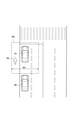
- the scene shown in FIG. 2 is a scene in which the own vehicle 40 follows the preceding vehicle 41 and automatically travels.
- the detection range setting unit 25 sets the detection range R1.
- the detection range R1 is an area on the lane in which the own vehicle 40 travels.
- the size of the detection range R1 will be described.
- the length of the detection range R1 in the vehicle width direction is the vehicle width W1 of the own vehicle 40 as shown in FIG.
- the length of the detection range R1 in the traveling direction is from the tip of the own vehicle 40 to the tip of the preceding vehicle 41.
- the size of the detection range R1 is not limited to FIG.
- the length in the vehicle width direction may be the width W2 of the lane in which the own vehicle 40 travels. Further, the length in the traveling direction may be from the tip of the own vehicle 40 to the rear end of the preceding vehicle 41.
- the detection ranges R1 to R2 described with reference to FIGS. 2 to 3 are areas set when the own vehicle 40 follows the preceding vehicle 41 and automatically travels. Next, the detection range when the own vehicle 40 is stopped will be described with reference to FIG.
- the scene shown in FIG. 4 is a scene in which the preceding vehicle 41 and the own vehicle 40 are stopped due to waiting for a traffic light. After the preceding vehicle 41 has stopped, the following traveling unit 23 automatically stops the own vehicle 40 when it is determined that the inter-vehicle distance is equal to or less than a predetermined value. At this time, the following traveling unit 23 keeps the stopped state.
- the detection range setting unit 25 expands the detection range in the vehicle width direction as compared with the case where the own vehicle 40 is traveling.
- the expanded detection range is shown in FIG. 4 as R3.
- the detection range R3 shown in FIG. 4 is wider in the vehicle width direction than the detection range R1 shown in FIG. 2 or the detection range R2 shown in FIG.
- the controller 20 may enter the front of the own vehicle 40 in a wider range than when the own vehicle 40 is running (pedestrian 50). Can be detected.
- the controller 20 can quickly detect an object which may enter the front of the own vehicle as compared with the case where the own vehicle 40 is traveling.
- the controller 20 detects the pedestrian 50 in the detection range R3 when the own vehicle 40 is stopped, the behavior of the own vehicle 40 can be restricted. Details will be described later.
- the length in the vehicle width direction is about twice the vehicle width of the own vehicle 40. This length is determined in consideration of a margin for detecting the pedestrian 50 before the own vehicle 40 starts. Therefore, doubling is an example and is not limited.
- the length in the traveling direction is from the tip of the own vehicle 40 to the tip of the preceding vehicle 41. Although not particularly limited, as a specific numerical value, the length in the vehicle width direction may be 3 m and the length in the traveling direction may be 10 m.
- the behavior of the own vehicle 40 when the pedestrian 50 is detected in the detection range R3 and when the pedestrian 50 is not detected will be described.
- the own vehicle 40 does not start automatically.
- the own vehicle 40 does not automatically start unless the user's start instruction (follow-up start instruction) is input.
- the follow-up start instruction is input by operating a switch for starting follow-up running or operating the accelerator pedal.
- the follow-up traveling unit 23 prohibits the follow-up start while the pedestrian 50 is detected. After that, when the pedestrian 50 is not detected in the detection range R3, the following traveling unit 23 automatically starts the own vehicle 40.
- the following traveling unit 23 may cancel the following starting system.
- the own vehicle 40 does not start automatically.
- the follow-up start is prevented in the area where the pedestrian 50 may pass in front of the own vehicle 40.
- the user since the user cannot use the follow-up start system, the user needs to manually start the own vehicle 40.
- the own vehicle 40 can be started with the user confirming the front. Even if the follow-up start system is released, the stopped state is maintained.
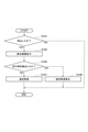
- step S101 the stop determination unit 24 determines whether or not the own vehicle 40 has stopped using the speed of the own vehicle 40 measured by the vehicle speed sensor 13.
- the process proceeds to step S103.
- the speed of the own vehicle 40 is not 0 km / h (NO in step S101)
- a series of processes is completed.
- step S103 the detection range setting unit 25 expands the detection range in the vehicle width direction as compared with the case where the own vehicle 40 is traveling (see FIG. 4).
- step S105 the process proceeds to step S105, and when the pedestrian 50 is detected in the expanded detection range R3 (YES in step S105), the following traveling unit 23 prohibits the following start. That is, the following traveling unit 23 releases the following starting system. On the other hand, when the pedestrian 50 is not detected in the expanded detection range R3 (NO in step S105), the following traveling unit 23 automatically sets the own vehicle 40 to follow the preceding vehicle 41 according to the following starting instruction from the user. To start.
- the detection range setting unit 25 sets the detection range of the sensor for detecting an object in front of the own vehicle 40.
- the detection range setting unit 25 expands the detection range in the vehicle width direction as compared with the case where the own vehicle 40 follows the preceding vehicle 41 and travels (see FIG. 4). ).
- the controller 20 may enter the front of the own vehicle 40 in a wider range than when the own vehicle 40 is running (pedestrian 50). Can be detected.
- the controller 20 can quickly detect an object which may enter the front of the own vehicle as compared with the case where the own vehicle 40 is traveling.
- the detection range when the own vehicle 40 is running is smaller than when the own vehicle 40 is stopped.
- the controller 20 can prevent control based on objects (adjacent traveling vehicles, trees, pedestrians walking on the sidewalk, etc.) excluding objects that may interfere with follow-up control. ..
- the adjacent traveling vehicle refers to a vehicle traveling in a lane adjacent to the lane in which the own vehicle 40 travels.
- the following traveling unit 23 prohibits the own vehicle 40 from following the preceding vehicle 41 and starting.
- the follow-up start is prevented in the area where the pedestrian 50 may pass in front of the own vehicle 40.
- the user since the user cannot use the follow-up start system, the user needs to manually start the own vehicle 40. As a result, the own vehicle 40 can be started with the user confirming the front.
- the controller 20 may determine whether or not the own vehicle 40 is traveling on the motorway based on the position information of the own vehicle 40.
- a motorway is defined in Japan as a road where only cars designated by the road administrator are allowed to drive.
- a typical motorway is a highway.
- the controller 20 starts the own vehicle 40 following the preceding vehicle 41. You may be prohibited from doing so.
- the fact that the pedestrian 50 or the bicycle is detected on the motorway where the pedestrian 50 or the bicycle does not exist may mean that erroneous position information is recognized due to a decrease in the accuracy of the GPS receiver 14. In such a case, the controller 20 prohibits the follow-up start, thereby improving the reliability of the system.
- the detection range setting unit 25 explained that the detection range is expanded by triggering the stop of the own vehicle 40, but this is not necessarily limited to expanding the detection range at the moment when the own vehicle 40 stops. That is, after the own vehicle 40 has stopped, the detection range setting unit 25 may not change the detection range until a predetermined time has elapsed, and may expand the detection range after the predetermined time has elapsed. This is realized by setting two modes (first mode and second mode) as modes for permitting follow-up start.
- the first mode and the second mode will be described.
- the first mode is a mode for permitting a follow-up start when the preceding vehicle 41 starts before the first predetermined time elapses after the own vehicle 40 stops.
- the second mode is a mode for permitting a follow-up start when the preceding vehicle 41 starts before the second predetermined time, which is longer than the first predetermined time, elapses.
- An example of the first predetermined time is 3 seconds, and an example of the second predetermined time is 30 seconds.
- the first mode and the second mode are set by the controller 20.
- the detection range setting unit 25 does not change the detection range in the first mode, and can expand the detection range in the second mode.
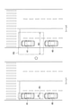
- the scene 1 shown in FIG. 6 is a scene from the time when the own vehicle 40 is stopped until the first predetermined time (3 seconds) elapses. That is, in the scene 1, the mode of the own vehicle 40 is the first mode. As shown in FIG. 6, the detection range setting unit 25 does not change the detection range R1 in the first mode.
- the scene 2 shown in FIG. 6 is a scene from the elapse of the first predetermined time (3 seconds) to the elapse of the second predetermined time (30 seconds). That is, in the scene 2, the mode of the own vehicle 40 is the second mode.
- the detection range setting unit 25 expands the detection range R1 in the vehicle width direction in the second mode (the expanded detection range is shown as R3).
- the start permission time is longer than in the first mode. If the start permission time is extended, the stop time is also extended. Therefore, by expanding the detection range in the vehicle width direction in the second mode, it becomes easier to detect the object. If the preceding vehicle 41 does not start even after the second predetermined time has elapsed, the following traveling unit 23 cancels the following starting system.
- the detection range set by the detection range setting unit 25 is the detection range of the camera 10.
- the object detected by the camera 10 is at least one of the pedestrian 50 and the bicycle.
- the controller 20 may detect the pedestrian 50 or the bicycle based on the change in the rear end of the preceding vehicle 41 shown in the camera image.
- the controller 20 may determine that the pedestrian 50 or the bicycle is present.
- the controller 20 can detect a pedestrian 50 or a bicycle having a shape that is difficult to recognize as an object.
- the processing circuit includes a programmed processing device such as a processing device including an electric circuit.
- Processing circuits also include devices such as application specific integrated circuits (ASICs) and circuit components arranged to perform the described functions.
- ASICs application specific integrated circuits
- the sensor for detecting an object in the detection range set by the detection range setting unit 25 has been described as the camera 10, but the sonar 12 may be added in addition to the camera 10.
- the detection target of the camera 10 is a pedestrian 50 or a bicycle, but the detection target of the sonar 12 is not particularly limited.
- a method of detecting an object by the sonar 12 will be described.
- the detection range set by the detection range setting unit 25 is the detection range R1 as shown in FIG. Since the size of the detection range R1 has been described above, the description thereof will be omitted.
- Driving support device 10 Camera 11 Radar 12 Sonar 13 Vehicle speed sensor 14 GPS receiver 15 Switch 20 Controller 21 Lane detection unit 22 Leading vehicle detection unit 23 Follow-up traveling unit 24 Stop judgment unit 25 Detection range setting unit 30 Steering actuator 31 Accelerator pedal actuator 32 Brake actuator
Landscapes
- Engineering & Computer Science (AREA)
- Transportation (AREA)
- Mechanical Engineering (AREA)
- Automation & Control Theory (AREA)
- Physics & Mathematics (AREA)
- Chemical & Material Sciences (AREA)
- Combustion & Propulsion (AREA)
- General Physics & Mathematics (AREA)
- Multimedia (AREA)
- Theoretical Computer Science (AREA)
- Mathematical Physics (AREA)
- Traffic Control Systems (AREA)
- Control Of Driving Devices And Active Controlling Of Vehicle (AREA)
Priority Applications (7)
| Application Number | Priority Date | Filing Date | Title |
|---|---|---|---|
| MX2023002335A MX2023002335A (es) | 2020-08-28 | 2020-08-28 | Metodo de asistencia a la conduccion y dispositivo de asistencia a la conduccion. |
| EP20951515.4A EP4212400B1 (en) | 2020-08-28 | 2020-08-28 | Driving assistance method and driving assistance device |
| PCT/JP2020/032623 WO2022044264A1 (ja) | 2020-08-28 | 2020-08-28 | 運転支援方法及び運転支援装置 |
| US18/043,065 US12344238B2 (en) | 2020-08-28 | 2020-08-28 | Driving assistance method and driving assistance device |
| JP2022545204A JP7380894B2 (ja) | 2020-08-28 | 2020-08-28 | 運転支援方法及び運転支援装置 |
| BR112023003418A BR112023003418A2 (pt) | 2020-08-28 | 2020-08-28 | Método de assistência à condução e dispositivo de assistência à condução |
| CN202080103650.2A CN116096612B (zh) | 2020-08-28 | 2020-08-28 | 驾驶辅助方法以及驾驶辅助装置 |
Applications Claiming Priority (1)
| Application Number | Priority Date | Filing Date | Title |
|---|---|---|---|
| PCT/JP2020/032623 WO2022044264A1 (ja) | 2020-08-28 | 2020-08-28 | 運転支援方法及び運転支援装置 |
Publications (1)
| Publication Number | Publication Date |
|---|---|
| WO2022044264A1 true WO2022044264A1 (ja) | 2022-03-03 |
Family
ID=80352970
Family Applications (1)
| Application Number | Title | Priority Date | Filing Date |
|---|---|---|---|
| PCT/JP2020/032623 Ceased WO2022044264A1 (ja) | 2020-08-28 | 2020-08-28 | 運転支援方法及び運転支援装置 |
Country Status (7)
| Country | Link |
|---|---|
| US (1) | US12344238B2 (https=) |
| EP (1) | EP4212400B1 (https=) |
| JP (1) | JP7380894B2 (https=) |
| CN (1) | CN116096612B (https=) |
| BR (1) | BR112023003418A2 (https=) |
| MX (1) | MX2023002335A (https=) |
| WO (1) | WO2022044264A1 (https=) |
Cited By (1)
| Publication number | Priority date | Publication date | Assignee | Title |
|---|---|---|---|---|
| JP2025037018A (ja) * | 2023-09-05 | 2025-03-17 | トヨタ自動車株式会社 | 運転支援装置 |
Families Citing this family (2)
| Publication number | Priority date | Publication date | Assignee | Title |
|---|---|---|---|---|
| JP2022123419A (ja) * | 2021-02-12 | 2022-08-24 | 本田技研工業株式会社 | 情報記録装置、情報記録方法、およびプログラム |
| JP2024130731A (ja) * | 2023-03-15 | 2024-09-30 | 本田技研工業株式会社 | 運転支援装置、運転支援方法、およびプログラム |
Citations (6)
| Publication number | Priority date | Publication date | Assignee | Title |
|---|---|---|---|---|
| JP2004224093A (ja) * | 2003-01-21 | 2004-08-12 | Hitachi Ltd | 車両の自動速度制御装置 |
| JP2006007918A (ja) * | 2004-06-24 | 2006-01-12 | Nissan Motor Co Ltd | 車両走行制御装置 |
| JP2010038731A (ja) * | 2008-08-05 | 2010-02-18 | Fujitsu Ten Ltd | レーダ装置 |
| JP2010089661A (ja) * | 2008-10-08 | 2010-04-22 | Honda Motor Co Ltd | 車両の周辺監視装置 |
| JP2014146135A (ja) * | 2013-01-28 | 2014-08-14 | Mazda Motor Corp | 車両用撮像装置 |
| WO2017009940A1 (ja) | 2015-07-14 | 2017-01-19 | 日産自動車株式会社 | 発進制御装置及び発進制御方法 |
Family Cites Families (12)
| Publication number | Priority date | Publication date | Assignee | Title |
|---|---|---|---|---|
| GB9601691D0 (en) * | 1996-01-27 | 1996-03-27 | Rover Group | A cruise control system for a motor vehicle |
| US6810330B2 (en) * | 2001-07-31 | 2004-10-26 | Omron Corporation | Apparatus for and method of detecting object on road |
| DE102004047177A1 (de) * | 2004-09-29 | 2006-04-13 | Robert Bosch Gmbh | Anfahrassistent für Kraftfahrzeuge |
| JP5454695B2 (ja) * | 2010-09-08 | 2014-03-26 | トヨタ自動車株式会社 | 危険度算出装置 |
| JP6478338B2 (ja) * | 2017-02-08 | 2019-03-06 | 株式会社Subaru | 車両の追従発進制御装置 |
| JP6822309B2 (ja) * | 2017-05-16 | 2021-01-27 | 株式会社デンソー | 自動運転支援装置および自動運転支援方法 |
| US10787172B2 (en) * | 2017-05-19 | 2020-09-29 | Nissan Motor Co., Ltd. | Driving assistance device and driving assistance method |
| JP6766783B2 (ja) * | 2017-08-31 | 2020-10-14 | トヨタ自動車株式会社 | 車両制御装置 |
| CN111542464B (zh) * | 2018-01-22 | 2021-09-07 | 日产自动车株式会社 | 车辆控制方法及车辆控制装置 |
| DE102019205542A1 (de) * | 2018-05-09 | 2019-11-14 | Ford Global Technologies, Llc | Verfahren und Vorrichtung zur bildhaften Information über Querverkehr auf einer Anzeigevorrichtung eines gefahrenen Fahrzeugs |
| DE102018009434A1 (de) * | 2018-11-30 | 2020-06-04 | Zf Active Safety Gmbh | Steuerungssystem und -Verfahren für ein Kraftfahrzeug zur Verarbeitung von mehrfach reflektierten Signalen |
| JP7441255B2 (ja) * | 2022-03-17 | 2024-02-29 | 本田技研工業株式会社 | 制御装置、制御装置の動作方法、プログラム及び記憶媒体 |
-
2020
- 2020-08-28 BR BR112023003418A patent/BR112023003418A2/pt not_active Application Discontinuation
- 2020-08-28 CN CN202080103650.2A patent/CN116096612B/zh active Active
- 2020-08-28 MX MX2023002335A patent/MX2023002335A/es unknown
- 2020-08-28 WO PCT/JP2020/032623 patent/WO2022044264A1/ja not_active Ceased
- 2020-08-28 US US18/043,065 patent/US12344238B2/en active Active
- 2020-08-28 EP EP20951515.4A patent/EP4212400B1/en active Active
- 2020-08-28 JP JP2022545204A patent/JP7380894B2/ja active Active
Patent Citations (6)
| Publication number | Priority date | Publication date | Assignee | Title |
|---|---|---|---|---|
| JP2004224093A (ja) * | 2003-01-21 | 2004-08-12 | Hitachi Ltd | 車両の自動速度制御装置 |
| JP2006007918A (ja) * | 2004-06-24 | 2006-01-12 | Nissan Motor Co Ltd | 車両走行制御装置 |
| JP2010038731A (ja) * | 2008-08-05 | 2010-02-18 | Fujitsu Ten Ltd | レーダ装置 |
| JP2010089661A (ja) * | 2008-10-08 | 2010-04-22 | Honda Motor Co Ltd | 車両の周辺監視装置 |
| JP2014146135A (ja) * | 2013-01-28 | 2014-08-14 | Mazda Motor Corp | 車両用撮像装置 |
| WO2017009940A1 (ja) | 2015-07-14 | 2017-01-19 | 日産自動車株式会社 | 発進制御装置及び発進制御方法 |
Non-Patent Citations (1)
| Title |
|---|
| See also references of EP4212400A4 |
Cited By (3)
| Publication number | Priority date | Publication date | Assignee | Title |
|---|---|---|---|---|
| JP2025037018A (ja) * | 2023-09-05 | 2025-03-17 | トヨタ自動車株式会社 | 運転支援装置 |
| US12503105B2 (en) | 2023-09-05 | 2025-12-23 | Toyota Jidosha Kabushiki Kaisha | Drive assist device |
| JP7845317B2 (ja) | 2023-09-05 | 2026-04-14 | トヨタ自動車株式会社 | 運転支援装置 |
Also Published As
| Publication number | Publication date |
|---|---|
| BR112023003418A2 (pt) | 2023-03-21 |
| CN116096612A (zh) | 2023-05-09 |
| JPWO2022044264A1 (https=) | 2022-03-03 |
| EP4212400A1 (en) | 2023-07-19 |
| EP4212400A4 (en) | 2024-01-10 |
| US12344238B2 (en) | 2025-07-01 |
| CN116096612B (zh) | 2025-08-05 |
| JP7380894B2 (ja) | 2023-11-15 |
| US20230303065A1 (en) | 2023-09-28 |
| MX2023002335A (es) | 2023-03-22 |
| EP4212400B1 (en) | 2025-03-05 |
Similar Documents
| Publication | Publication Date | Title |
|---|---|---|
| JP6623501B2 (ja) | 車両制御装置、車両制御方法、および車両制御プログラム | |
| JP7469896B2 (ja) | 周辺認識装置、周辺認識方法、およびプログラム | |
| US10754335B2 (en) | Automated driving system | |
| JP7497789B2 (ja) | 車両制御装置 | |
| JP2019151185A (ja) | 運転支援装置 | |
| US12570313B2 (en) | Vehicle control device and method for controlling vehicle | |
| JP7380894B2 (ja) | 運転支援方法及び運転支援装置 | |
| JP2012226635A (ja) | 車両の衝突予防安全装置 | |
| JP2023105692A (ja) | 車両の運転支援装置 | |
| JP6669267B2 (ja) | 車両の走行制御方法および走行制御装置 | |
| JP7425420B2 (ja) | 運転支援方法及び運転支援装置 | |
| JP2005145282A (ja) | 車両走行支援装置 | |
| JP2025061981A (ja) | 車両用制御装置及び車両用制御方法 | |
| JP7768075B2 (ja) | 制御装置、制御方法およびコンピュータプログラム | |
| US12344248B2 (en) | Method and device for controlling vehicle acceleration on a curved road using curve information | |
| EP4206053B1 (en) | Driving support method and driving support device | |
| JP7334107B2 (ja) | 車両制御方法及び車両制御装置 | |
| RU2803100C1 (ru) | Способ помощи при вождении и устройство помощи при вождении | |
| JP2023027669A (ja) | 車両用制御装置及び車両用制御方法 | |
| JP2026048488A (ja) | 車両用制御装置 |
Legal Events
| Date | Code | Title | Description |
|---|---|---|---|
| 121 | Ep: the epo has been informed by wipo that ep was designated in this application |
Ref document number: 20951515 Country of ref document: EP Kind code of ref document: A1 |
|
| ENP | Entry into the national phase |
Ref document number: 2022545204 Country of ref document: JP Kind code of ref document: A |
|
| REG | Reference to national code |
Ref country code: BR Ref legal event code: B01A Ref document number: 112023003418 Country of ref document: BR |
|
| WWE | Wipo information: entry into national phase |
Ref document number: 202317017813 Country of ref document: IN |
|
| ENP | Entry into the national phase |
Ref document number: 112023003418 Country of ref document: BR Kind code of ref document: A2 Effective date: 20230224 |
|
| NENP | Non-entry into the national phase |
Ref country code: DE |
|
| ENP | Entry into the national phase |
Ref document number: 2020951515 Country of ref document: EP Effective date: 20230328 |
|
| WWG | Wipo information: grant in national office |
Ref document number: 18043065 Country of ref document: US |
|
| WWG | Wipo information: grant in national office |
Ref document number: 202080103650.2 Country of ref document: CN |