WO2022044264A1 - Driving assistance method and driving assistance device - Google Patents
Driving assistance method and driving assistance device Download PDFInfo
- Publication number
- WO2022044264A1 WO2022044264A1 PCT/JP2020/032623 JP2020032623W WO2022044264A1 WO 2022044264 A1 WO2022044264 A1 WO 2022044264A1 JP 2020032623 W JP2020032623 W JP 2020032623W WO 2022044264 A1 WO2022044264 A1 WO 2022044264A1
- Authority
- WO
- WIPO (PCT)
- Prior art keywords
- vehicle
- detection range
- controller
- driving support
- preceding vehicle
- Prior art date
Links
- 238000000034 method Methods 0.000 title claims description 20
- 238000001514 detection method Methods 0.000 claims abstract description 94
- 238000010586 diagram Methods 0.000 description 6
- 230000006870 function Effects 0.000 description 6
- 230000010365 information processing Effects 0.000 description 6
- 238000004590 computer program Methods 0.000 description 2
- 230000000694 effects Effects 0.000 description 2
- 230000001133 acceleration Effects 0.000 description 1
- 230000003044 adaptive effect Effects 0.000 description 1
- 230000000295 complement effect Effects 0.000 description 1
- 239000000284 extract Substances 0.000 description 1
- 229910044991 metal oxide Inorganic materials 0.000 description 1
- 150000004706 metal oxides Chemical class 0.000 description 1
- 239000004065 semiconductor Substances 0.000 description 1
Images


Classifications
-
- B—PERFORMING OPERATIONS; TRANSPORTING
- B60—VEHICLES IN GENERAL
- B60W—CONJOINT CONTROL OF VEHICLE SUB-UNITS OF DIFFERENT TYPE OR DIFFERENT FUNCTION; CONTROL SYSTEMS SPECIALLY ADAPTED FOR HYBRID VEHICLES; ROAD VEHICLE DRIVE CONTROL SYSTEMS FOR PURPOSES NOT RELATED TO THE CONTROL OF A PARTICULAR SUB-UNIT
- B60W30/00—Purposes of road vehicle drive control systems not related to the control of a particular sub-unit, e.g. of systems using conjoint control of vehicle sub-units, or advanced driver assistance systems for ensuring comfort, stability and safety or drive control systems for propelling or retarding the vehicle
- B60W30/14—Adaptive cruise control
- B60W30/16—Control of distance between vehicles, e.g. keeping a distance to preceding vehicle
- B60W30/17—Control of distance between vehicles, e.g. keeping a distance to preceding vehicle with provision for special action when the preceding vehicle comes to a halt, e.g. stop and go
-
- B—PERFORMING OPERATIONS; TRANSPORTING
- B60—VEHICLES IN GENERAL
- B60W—CONJOINT CONTROL OF VEHICLE SUB-UNITS OF DIFFERENT TYPE OR DIFFERENT FUNCTION; CONTROL SYSTEMS SPECIALLY ADAPTED FOR HYBRID VEHICLES; ROAD VEHICLE DRIVE CONTROL SYSTEMS FOR PURPOSES NOT RELATED TO THE CONTROL OF A PARTICULAR SUB-UNIT
- B60W30/00—Purposes of road vehicle drive control systems not related to the control of a particular sub-unit, e.g. of systems using conjoint control of vehicle sub-units, or advanced driver assistance systems for ensuring comfort, stability and safety or drive control systems for propelling or retarding the vehicle
- B60W30/08—Active safety systems predicting or avoiding probable or impending collision or attempting to minimise its consequences
- B60W30/09—Taking automatic action to avoid collision, e.g. braking and steering
-
- B—PERFORMING OPERATIONS; TRANSPORTING
- B60—VEHICLES IN GENERAL
- B60W—CONJOINT CONTROL OF VEHICLE SUB-UNITS OF DIFFERENT TYPE OR DIFFERENT FUNCTION; CONTROL SYSTEMS SPECIALLY ADAPTED FOR HYBRID VEHICLES; ROAD VEHICLE DRIVE CONTROL SYSTEMS FOR PURPOSES NOT RELATED TO THE CONTROL OF A PARTICULAR SUB-UNIT
- B60W10/00—Conjoint control of vehicle sub-units of different type or different function
- B60W10/04—Conjoint control of vehicle sub-units of different type or different function including control of propulsion units
-
- B—PERFORMING OPERATIONS; TRANSPORTING
- B60—VEHICLES IN GENERAL
- B60W—CONJOINT CONTROL OF VEHICLE SUB-UNITS OF DIFFERENT TYPE OR DIFFERENT FUNCTION; CONTROL SYSTEMS SPECIALLY ADAPTED FOR HYBRID VEHICLES; ROAD VEHICLE DRIVE CONTROL SYSTEMS FOR PURPOSES NOT RELATED TO THE CONTROL OF A PARTICULAR SUB-UNIT
- B60W10/00—Conjoint control of vehicle sub-units of different type or different function
- B60W10/18—Conjoint control of vehicle sub-units of different type or different function including control of braking systems
- B60W10/184—Conjoint control of vehicle sub-units of different type or different function including control of braking systems with wheel brakes
-
- B—PERFORMING OPERATIONS; TRANSPORTING
- B60—VEHICLES IN GENERAL
- B60W—CONJOINT CONTROL OF VEHICLE SUB-UNITS OF DIFFERENT TYPE OR DIFFERENT FUNCTION; CONTROL SYSTEMS SPECIALLY ADAPTED FOR HYBRID VEHICLES; ROAD VEHICLE DRIVE CONTROL SYSTEMS FOR PURPOSES NOT RELATED TO THE CONTROL OF A PARTICULAR SUB-UNIT
- B60W10/00—Conjoint control of vehicle sub-units of different type or different function
- B60W10/20—Conjoint control of vehicle sub-units of different type or different function including control of steering systems
-
- B—PERFORMING OPERATIONS; TRANSPORTING
- B60—VEHICLES IN GENERAL
- B60W—CONJOINT CONTROL OF VEHICLE SUB-UNITS OF DIFFERENT TYPE OR DIFFERENT FUNCTION; CONTROL SYSTEMS SPECIALLY ADAPTED FOR HYBRID VEHICLES; ROAD VEHICLE DRIVE CONTROL SYSTEMS FOR PURPOSES NOT RELATED TO THE CONTROL OF A PARTICULAR SUB-UNIT
- B60W30/00—Purposes of road vehicle drive control systems not related to the control of a particular sub-unit, e.g. of systems using conjoint control of vehicle sub-units, or advanced driver assistance systems for ensuring comfort, stability and safety or drive control systems for propelling or retarding the vehicle
- B60W30/14—Adaptive cruise control
- B60W30/16—Control of distance between vehicles, e.g. keeping a distance to preceding vehicle
- B60W30/165—Automatically following the path of a preceding lead vehicle, e.g. "electronic tow-bar"
-
- B—PERFORMING OPERATIONS; TRANSPORTING
- B60—VEHICLES IN GENERAL
- B60W—CONJOINT CONTROL OF VEHICLE SUB-UNITS OF DIFFERENT TYPE OR DIFFERENT FUNCTION; CONTROL SYSTEMS SPECIALLY ADAPTED FOR HYBRID VEHICLES; ROAD VEHICLE DRIVE CONTROL SYSTEMS FOR PURPOSES NOT RELATED TO THE CONTROL OF A PARTICULAR SUB-UNIT
- B60W30/00—Purposes of road vehicle drive control systems not related to the control of a particular sub-unit, e.g. of systems using conjoint control of vehicle sub-units, or advanced driver assistance systems for ensuring comfort, stability and safety or drive control systems for propelling or retarding the vehicle
- B60W30/18—Propelling the vehicle
- B60W30/18009—Propelling the vehicle related to particular drive situations
- B60W30/18027—Drive off, accelerating from standstill
-
- B—PERFORMING OPERATIONS; TRANSPORTING
- B60—VEHICLES IN GENERAL
- B60W—CONJOINT CONTROL OF VEHICLE SUB-UNITS OF DIFFERENT TYPE OR DIFFERENT FUNCTION; CONTROL SYSTEMS SPECIALLY ADAPTED FOR HYBRID VEHICLES; ROAD VEHICLE DRIVE CONTROL SYSTEMS FOR PURPOSES NOT RELATED TO THE CONTROL OF A PARTICULAR SUB-UNIT
- B60W30/00—Purposes of road vehicle drive control systems not related to the control of a particular sub-unit, e.g. of systems using conjoint control of vehicle sub-units, or advanced driver assistance systems for ensuring comfort, stability and safety or drive control systems for propelling or retarding the vehicle
- B60W30/18—Propelling the vehicle
- B60W30/182—Selecting between different operative modes, e.g. comfort and performance modes
-
- B—PERFORMING OPERATIONS; TRANSPORTING
- B60—VEHICLES IN GENERAL
- B60W—CONJOINT CONTROL OF VEHICLE SUB-UNITS OF DIFFERENT TYPE OR DIFFERENT FUNCTION; CONTROL SYSTEMS SPECIALLY ADAPTED FOR HYBRID VEHICLES; ROAD VEHICLE DRIVE CONTROL SYSTEMS FOR PURPOSES NOT RELATED TO THE CONTROL OF A PARTICULAR SUB-UNIT
- B60W40/00—Estimation or calculation of non-directly measurable driving parameters for road vehicle drive control systems not related to the control of a particular sub unit, e.g. by using mathematical models
- B60W40/02—Estimation or calculation of non-directly measurable driving parameters for road vehicle drive control systems not related to the control of a particular sub unit, e.g. by using mathematical models related to ambient conditions
-
- G—PHYSICS
- G06—COMPUTING; CALCULATING OR COUNTING
- G06V—IMAGE OR VIDEO RECOGNITION OR UNDERSTANDING
- G06V20/00—Scenes; Scene-specific elements
- G06V20/50—Context or environment of the image
- G06V20/56—Context or environment of the image exterior to a vehicle by using sensors mounted on the vehicle
- G06V20/58—Recognition of moving objects or obstacles, e.g. vehicles or pedestrians; Recognition of traffic objects, e.g. traffic signs, traffic lights or roads
-
- B—PERFORMING OPERATIONS; TRANSPORTING
- B60—VEHICLES IN GENERAL
- B60W—CONJOINT CONTROL OF VEHICLE SUB-UNITS OF DIFFERENT TYPE OR DIFFERENT FUNCTION; CONTROL SYSTEMS SPECIALLY ADAPTED FOR HYBRID VEHICLES; ROAD VEHICLE DRIVE CONTROL SYSTEMS FOR PURPOSES NOT RELATED TO THE CONTROL OF A PARTICULAR SUB-UNIT
- B60W2420/00—Indexing codes relating to the type of sensors based on the principle of their operation
- B60W2420/40—Photo or light sensitive means, e.g. infrared sensors
- B60W2420/403—Image sensing, e.g. optical camera
-
- B60W2420/408—
-
- B—PERFORMING OPERATIONS; TRANSPORTING
- B60—VEHICLES IN GENERAL
- B60W—CONJOINT CONTROL OF VEHICLE SUB-UNITS OF DIFFERENT TYPE OR DIFFERENT FUNCTION; CONTROL SYSTEMS SPECIALLY ADAPTED FOR HYBRID VEHICLES; ROAD VEHICLE DRIVE CONTROL SYSTEMS FOR PURPOSES NOT RELATED TO THE CONTROL OF A PARTICULAR SUB-UNIT
- B60W2520/00—Input parameters relating to overall vehicle dynamics
- B60W2520/10—Longitudinal speed
-
- B—PERFORMING OPERATIONS; TRANSPORTING
- B60—VEHICLES IN GENERAL
- B60W—CONJOINT CONTROL OF VEHICLE SUB-UNITS OF DIFFERENT TYPE OR DIFFERENT FUNCTION; CONTROL SYSTEMS SPECIALLY ADAPTED FOR HYBRID VEHICLES; ROAD VEHICLE DRIVE CONTROL SYSTEMS FOR PURPOSES NOT RELATED TO THE CONTROL OF A PARTICULAR SUB-UNIT
- B60W2552/00—Input parameters relating to infrastructure
- B60W2552/05—Type of road
-
- B—PERFORMING OPERATIONS; TRANSPORTING
- B60—VEHICLES IN GENERAL
- B60W—CONJOINT CONTROL OF VEHICLE SUB-UNITS OF DIFFERENT TYPE OR DIFFERENT FUNCTION; CONTROL SYSTEMS SPECIALLY ADAPTED FOR HYBRID VEHICLES; ROAD VEHICLE DRIVE CONTROL SYSTEMS FOR PURPOSES NOT RELATED TO THE CONTROL OF A PARTICULAR SUB-UNIT
- B60W2554/00—Input parameters relating to objects
- B60W2554/40—Dynamic objects, e.g. animals, windblown objects
- B60W2554/402—Type
- B60W2554/4026—Cycles
-
- B—PERFORMING OPERATIONS; TRANSPORTING
- B60—VEHICLES IN GENERAL
- B60W—CONJOINT CONTROL OF VEHICLE SUB-UNITS OF DIFFERENT TYPE OR DIFFERENT FUNCTION; CONTROL SYSTEMS SPECIALLY ADAPTED FOR HYBRID VEHICLES; ROAD VEHICLE DRIVE CONTROL SYSTEMS FOR PURPOSES NOT RELATED TO THE CONTROL OF A PARTICULAR SUB-UNIT
- B60W2554/00—Input parameters relating to objects
- B60W2554/40—Dynamic objects, e.g. animals, windblown objects
- B60W2554/402—Type
- B60W2554/4029—Pedestrians
-
- B—PERFORMING OPERATIONS; TRANSPORTING
- B60—VEHICLES IN GENERAL
- B60W—CONJOINT CONTROL OF VEHICLE SUB-UNITS OF DIFFERENT TYPE OR DIFFERENT FUNCTION; CONTROL SYSTEMS SPECIALLY ADAPTED FOR HYBRID VEHICLES; ROAD VEHICLE DRIVE CONTROL SYSTEMS FOR PURPOSES NOT RELATED TO THE CONTROL OF A PARTICULAR SUB-UNIT
- B60W2554/00—Input parameters relating to objects
- B60W2554/80—Spatial relation or speed relative to objects
- B60W2554/802—Longitudinal distance
-
- B—PERFORMING OPERATIONS; TRANSPORTING
- B60—VEHICLES IN GENERAL
- B60W—CONJOINT CONTROL OF VEHICLE SUB-UNITS OF DIFFERENT TYPE OR DIFFERENT FUNCTION; CONTROL SYSTEMS SPECIALLY ADAPTED FOR HYBRID VEHICLES; ROAD VEHICLE DRIVE CONTROL SYSTEMS FOR PURPOSES NOT RELATED TO THE CONTROL OF A PARTICULAR SUB-UNIT
- B60W2554/00—Input parameters relating to objects
- B60W2554/80—Spatial relation or speed relative to objects
- B60W2554/804—Relative longitudinal speed
-
- B—PERFORMING OPERATIONS; TRANSPORTING
- B60—VEHICLES IN GENERAL
- B60W—CONJOINT CONTROL OF VEHICLE SUB-UNITS OF DIFFERENT TYPE OR DIFFERENT FUNCTION; CONTROL SYSTEMS SPECIALLY ADAPTED FOR HYBRID VEHICLES; ROAD VEHICLE DRIVE CONTROL SYSTEMS FOR PURPOSES NOT RELATED TO THE CONTROL OF A PARTICULAR SUB-UNIT
- B60W2555/00—Input parameters relating to exterior conditions, not covered by groups B60W2552/00, B60W2554/00
- B60W2555/60—Traffic rules, e.g. speed limits or right of way
-
- B—PERFORMING OPERATIONS; TRANSPORTING
- B60—VEHICLES IN GENERAL
- B60W—CONJOINT CONTROL OF VEHICLE SUB-UNITS OF DIFFERENT TYPE OR DIFFERENT FUNCTION; CONTROL SYSTEMS SPECIALLY ADAPTED FOR HYBRID VEHICLES; ROAD VEHICLE DRIVE CONTROL SYSTEMS FOR PURPOSES NOT RELATED TO THE CONTROL OF A PARTICULAR SUB-UNIT
- B60W2556/00—Input parameters relating to data
- B60W2556/45—External transmission of data to or from the vehicle
- B60W2556/50—External transmission of data to or from the vehicle for navigation systems
Abstract
Description
以上説明したように、本実施形態に係る運転支援装置1によれば、以下の作用効果が得られる。 (Action effect)
As described above, according to the driving support device 1 according to the present embodiment, the following effects can be obtained.
10 カメラ
11 レーダ
12 ソナー
13 車速センサ
14 GPS受信機
15 スイッチ
20 コントローラ
21 車線検出部
22 先行車両検出部
23 追従走行部
24 停止判断部
25 検出範囲設定部
30 ステアリングアクチュエータ
31 アクセルペダルアクチュエータ
32 ブレーキアクチュエータ 1 Driving
Claims (7)
- 自車両の前方に存在する先行車両に追従して自動的に走行するように前記自車両を制御するコントローラを備える運転支援方法であって、
前記コントローラは、
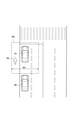
前記自車両の前方において物体を検出するためのセンサの検出範囲を設定し、
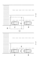
前記自車両が停止しているときは、前記自車両が前記先行車両に追従して走行しているときと比較して、前記検出範囲を車幅方向に拡げる
ことを特徴とする運転支援方法。 It is a driving support method including a controller that controls the own vehicle so as to automatically follow the preceding vehicle existing in front of the own vehicle.
The controller
Set the detection range of the sensor for detecting an object in front of the own vehicle,
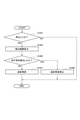
A driving support method characterized in that when the own vehicle is stopped, the detection range is expanded in the vehicle width direction as compared with the case where the own vehicle is traveling following the preceding vehicle. - 前記コントローラは、前記車幅方向に拡げられた検出範囲で前記物体が検出された場合、前記自車両が前記先行車両に追従して発進することを禁止する
ことを特徴とする請求項1に記載の運転支援方法。 The controller according to claim 1, wherein when the object is detected in the detection range expanded in the vehicle width direction, the own vehicle is prohibited from starting following the preceding vehicle. Driving support method. - 前記コントローラは、
前記自車両の位置情報を取得し、
前記位置情報に基づいて前記自車両が自動車専用道路を走行しているかどうかを判断し、
前記自車両が前記自動車専用道路を走行していると判断し、かつ、前記車幅方向に拡げられた検出範囲で前記物体が検出された場合、前記自車両が前記先行車両に追従して発進することを禁止する
ことを特徴とする請求項1または2に記載の運転支援方法。 The controller
Acquire the position information of the own vehicle and
Based on the position information, it is determined whether or not the own vehicle is traveling on the motorway.
When it is determined that the own vehicle is traveling on the motorway and the object is detected within the detection range expanded in the vehicle width direction, the own vehicle starts following the preceding vehicle. The driving support method according to claim 1 or 2, wherein the operation is prohibited. - 前記コントローラは、
前記自車両が停止してから第1所定時間が経過するまでに前記先行車両が発進した場合に前記先行車両に追従して発進することを許可する第1モードと、前記第1所定時間より長い第2所定時間が経過するまでに前記先行車両が発進した場合に前記先行車両に追従して発進することを許可する第2モードを設定し、
前記第2モードにおいて前記検出範囲を車幅方向に拡げる
ことを特徴とする請求項1~3のいずれか1項に記載の運転支援方法。 The controller
A first mode that permits the preceding vehicle to start following the preceding vehicle when the preceding vehicle starts before the first predetermined time elapses after the own vehicle stops, and a longer time than the first predetermined time. If the preceding vehicle starts by the time when the second predetermined time elapses, a second mode is set in which the preceding vehicle is allowed to start following the preceding vehicle.
The driving support method according to any one of claims 1 to 3, wherein the detection range is expanded in the vehicle width direction in the second mode. - 前記センサはカメラであり、
前記カメラが検出する物体は、少なくとも歩行者または自転車のいずれか一方である
ことを特徴とする請求項1~4のいずれか1項に記載の運転支援方法。 The sensor is a camera
The driving support method according to any one of claims 1 to 4, wherein the object detected by the camera is at least one of a pedestrian and a bicycle. - 前記カメラを用いて前記先行車両の後端部を撮像し、
前記コントローラは、前記カメラによって撮像された画像に写る前記後端部の変化に基づいて前記歩行者または前記自転車を検出する
ことを特徴とする請求項5に記載の運転支援方法。 The rear end of the preceding vehicle was imaged using the camera.
The driving support method according to claim 5, wherein the controller detects the pedestrian or the bicycle based on the change in the rear end portion of the image captured by the camera. - 自車両の前方に存在する先行車両に追従して自動的に走行するように前記自車両を制御する運転支援装置であって、
前記自車両の前方において物体を検出するセンサと、
コントローラと、を備え、
前記コントローラは、
前記センサの検出範囲を設定し、
前記自車両が停止しているときは、前記自車両が前記先行車両に追従して走行しているときと比較して、前記検出範囲を車幅方向に拡げる
ことを特徴とする運転支援装置。 It is a driving support device that controls the own vehicle so as to automatically follow the preceding vehicle existing in front of the own vehicle.
The sensor that detects an object in front of the own vehicle and
With a controller,
The controller
Set the detection range of the sensor
A driving support device characterized in that when the own vehicle is stopped, the detection range is expanded in the vehicle width direction as compared with the case where the own vehicle is traveling following the preceding vehicle.
Priority Applications (7)
| Application Number | Priority Date | Filing Date | Title |
|---|---|---|---|
| US18/043,065 US20230303065A1 (en) | 2020-08-28 | 2020-08-28 | Driving Assistance Method and Driving Assistance Device |
| CN202080103650.2A CN116096612A (en) | 2020-08-28 | 2020-08-28 | Driving support method and driving support device |
| PCT/JP2020/032623 WO2022044264A1 (en) | 2020-08-28 | 2020-08-28 | Driving assistance method and driving assistance device |
| EP20951515.4A EP4212400A4 (en) | 2020-08-28 | 2020-08-28 | Driving assistance method and driving assistance device |
| BR112023003418A BR112023003418A2 (en) | 2020-08-28 | 2020-08-28 | DRIVING ASSISTANCE METHOD AND DRIVING ASSISTANCE DEVICE |
| MX2023002335A MX2023002335A (en) | 2020-08-28 | 2020-08-28 | Driving assistance method and driving assistance device. |
| JP2022545204A JP7380894B2 (en) | 2020-08-28 | 2020-08-28 | Driving support method and driving support device |
Applications Claiming Priority (1)
| Application Number | Priority Date | Filing Date | Title |
|---|---|---|---|
| PCT/JP2020/032623 WO2022044264A1 (en) | 2020-08-28 | 2020-08-28 | Driving assistance method and driving assistance device |
Publications (1)
| Publication Number | Publication Date |
|---|---|
| WO2022044264A1 true WO2022044264A1 (en) | 2022-03-03 |
Family
ID=80352970
Family Applications (1)
| Application Number | Title | Priority Date | Filing Date |
|---|---|---|---|
| PCT/JP2020/032623 WO2022044264A1 (en) | 2020-08-28 | 2020-08-28 | Driving assistance method and driving assistance device |
Country Status (7)
| Country | Link |
|---|---|
| US (1) | US20230303065A1 (en) |
| EP (1) | EP4212400A4 (en) |
| JP (1) | JP7380894B2 (en) |
| CN (1) | CN116096612A (en) |
| BR (1) | BR112023003418A2 (en) |
| MX (1) | MX2023002335A (en) |
| WO (1) | WO2022044264A1 (en) |
Families Citing this family (1)
| Publication number | Priority date | Publication date | Assignee | Title |
|---|---|---|---|---|
| JP2022123419A (en) * | 2021-02-12 | 2022-08-24 | 本田技研工業株式会社 | Information recording device, information recording method, and program |
Citations (6)
| Publication number | Priority date | Publication date | Assignee | Title |
|---|---|---|---|---|
| JP2004224093A (en) * | 2003-01-21 | 2004-08-12 | Hitachi Ltd | Automatic speed control device for vehicle |
| JP2006007918A (en) * | 2004-06-24 | 2006-01-12 | Nissan Motor Co Ltd | Vehicle travel controlling device |
| JP2010038731A (en) * | 2008-08-05 | 2010-02-18 | Fujitsu Ten Ltd | Radar apparatus |
| JP2010089661A (en) * | 2008-10-08 | 2010-04-22 | Honda Motor Co Ltd | Vehicle periphery monitoring device |
| JP2014146135A (en) * | 2013-01-28 | 2014-08-14 | Mazda Motor Corp | Imaging device for vehicle |
| WO2017009940A1 (en) | 2015-07-14 | 2017-01-19 | 日産自動車株式会社 | Start control device and start control method |
Family Cites Families (2)
| Publication number | Priority date | Publication date | Assignee | Title |
|---|---|---|---|---|
| DE102004047177A1 (en) * | 2004-09-29 | 2006-04-13 | Robert Bosch Gmbh | Start-up assistant for motor vehicles |
| JP6478338B2 (en) * | 2017-02-08 | 2019-03-06 | 株式会社Subaru | Vehicle start control device |
-
2020
- 2020-08-28 JP JP2022545204A patent/JP7380894B2/en active Active
- 2020-08-28 MX MX2023002335A patent/MX2023002335A/en unknown
- 2020-08-28 CN CN202080103650.2A patent/CN116096612A/en active Pending
- 2020-08-28 US US18/043,065 patent/US20230303065A1/en active Pending
- 2020-08-28 WO PCT/JP2020/032623 patent/WO2022044264A1/en unknown
- 2020-08-28 EP EP20951515.4A patent/EP4212400A4/en active Pending
- 2020-08-28 BR BR112023003418A patent/BR112023003418A2/en unknown
Patent Citations (6)
| Publication number | Priority date | Publication date | Assignee | Title |
|---|---|---|---|---|
| JP2004224093A (en) * | 2003-01-21 | 2004-08-12 | Hitachi Ltd | Automatic speed control device for vehicle |
| JP2006007918A (en) * | 2004-06-24 | 2006-01-12 | Nissan Motor Co Ltd | Vehicle travel controlling device |
| JP2010038731A (en) * | 2008-08-05 | 2010-02-18 | Fujitsu Ten Ltd | Radar apparatus |
| JP2010089661A (en) * | 2008-10-08 | 2010-04-22 | Honda Motor Co Ltd | Vehicle periphery monitoring device |
| JP2014146135A (en) * | 2013-01-28 | 2014-08-14 | Mazda Motor Corp | Imaging device for vehicle |
| WO2017009940A1 (en) | 2015-07-14 | 2017-01-19 | 日産自動車株式会社 | Start control device and start control method |
Non-Patent Citations (1)
| Title |
|---|
| See also references of EP4212400A4 |
Also Published As
| Publication number | Publication date |
|---|---|
| CN116096612A (en) | 2023-05-09 |
| US20230303065A1 (en) | 2023-09-28 |
| MX2023002335A (en) | 2023-03-22 |
| EP4212400A4 (en) | 2024-01-10 |
| BR112023003418A2 (en) | 2023-03-21 |
| JPWO2022044264A1 (en) | 2022-03-03 |
| JP7380894B2 (en) | 2023-11-15 |
| EP4212400A1 (en) | 2023-07-19 |
Similar Documents
| Publication | Publication Date | Title |
|---|---|---|
| US10807608B2 (en) | Vehicle control system, vehicle control method, and storage medium | |
| US10676093B2 (en) | Vehicle control system, vehicle control method, and storage medium | |
| JP6623501B2 (en) | Vehicle control device, vehicle control method, and vehicle control program | |
| WO2017002650A1 (en) | In-lane driving control device and in-lane driving control method | |
| JP7119428B2 (en) | Driving support device | |
| JP7469896B2 (en) | Periphery recognition device, surroundings recognition method, and program | |
| JP2009248892A (en) | Travel control system | |
| JPWO2018012180A1 (en) | Traveling control method and traveling control device | |
| JP6669267B2 (en) | Vehicle traveling control method and traveling control device | |
| JP2012226635A (en) | Collision prevention safety device for vehicle | |
| JP4235090B2 (en) | Vehicle travel support device | |
| WO2022044266A1 (en) | Driving assistance method and driving assistance device | |
| WO2022044264A1 (en) | Driving assistance method and driving assistance device | |
| JP2020179731A (en) | Vehicle control apparatus | |
| JP7414497B2 (en) | Driving support device | |
| JP7334107B2 (en) | Vehicle control method and vehicle control device | |
| WO2022044253A1 (en) | Driving assistance method and driving assistance device | |
| RU2803100C1 (en) | Driving assistance method and driving assistance device | |
| WO2022038738A1 (en) | Driving assistance method and driving assistance device | |
| JP7485051B2 (en) | Driving assistance method and driving assistance device | |
| JP7421692B2 (en) | Vehicle control device | |
| JP7405124B2 (en) | Vehicle control device and vehicle control method | |
| WO2022185829A9 (en) | Vehicle control device and vehicle control method | |
| JP2023105692A (en) | Driving support device for vehicle | |
| JP2023027669A (en) | Vehicle controlling device and vehicle controlling method |
Legal Events
| Date | Code | Title | Description |
|---|---|---|---|
| 121 | Ep: the epo has been informed by wipo that ep was designated in this application |
Ref document number: 20951515 Country of ref document: EP Kind code of ref document: A1 |
|
| ENP | Entry into the national phase |
Ref document number: 2022545204 Country of ref document: JP Kind code of ref document: A |
|
| REG | Reference to national code |
Ref country code: BR Ref legal event code: B01A Ref document number: 112023003418 Country of ref document: BR |
|
| ENP | Entry into the national phase |
Ref document number: 112023003418 Country of ref document: BR Kind code of ref document: A2 Effective date: 20230224 |
|
| NENP | Non-entry into the national phase |
Ref country code: DE |
|
| ENP | Entry into the national phase |
Ref document number: 2020951515 Country of ref document: EP Effective date: 20230328 |