WO2022014449A1 - リチウムイオン二次電池用正極活物質、及びこれを用いたリチウムイオン二次電池 - Google Patents
リチウムイオン二次電池用正極活物質、及びこれを用いたリチウムイオン二次電池 Download PDFInfo
- Publication number
- WO2022014449A1 WO2022014449A1 PCT/JP2021/025695 JP2021025695W WO2022014449A1 WO 2022014449 A1 WO2022014449 A1 WO 2022014449A1 JP 2021025695 W JP2021025695 W JP 2021025695W WO 2022014449 A1 WO2022014449 A1 WO 2022014449A1
- Authority
- WO
- WIPO (PCT)
- Prior art keywords
- positive electrode
- active material
- electrode active
- lithium ion
- secondary battery
- Prior art date
- Legal status (The legal status is an assumption and is not a legal conclusion. Google has not performed a legal analysis and makes no representation as to the accuracy of the status listed.)
- Ceased
Links
Images




Classifications
-
- H—ELECTRICITY
- H01—ELECTRIC ELEMENTS
- H01M—PROCESSES OR MEANS, e.g. BATTERIES, FOR THE DIRECT CONVERSION OF CHEMICAL ENERGY INTO ELECTRICAL ENERGY
- H01M4/00—Electrodes
- H01M4/02—Electrodes composed of, or comprising, active material
- H01M4/36—Selection of substances as active materials, active masses, active liquids
- H01M4/48—Selection of substances as active materials, active masses, active liquids of inorganic oxides or hydroxides
- H01M4/52—Selection of substances as active materials, active masses, active liquids of inorganic oxides or hydroxides of nickel, cobalt or iron
- H01M4/525—Selection of substances as active materials, active masses, active liquids of inorganic oxides or hydroxides of nickel, cobalt or iron of mixed oxides or hydroxides containing iron, cobalt or nickel for inserting or intercalating light metals, e.g. LiNiO2, LiCoO2 or LiCoOxFy
-
- C—CHEMISTRY; METALLURGY
- C01—INORGANIC CHEMISTRY
- C01G—COMPOUNDS CONTAINING METALS NOT COVERED BY SUBCLASSES C01D OR C01F
- C01G51/00—Compounds of cobalt
- C01G51/40—Complex oxides containing cobalt and at least one other metal element
- C01G51/42—Complex oxides containing cobalt and at least one other metal element containing alkali metals, e.g. LiCoO2
- C01G51/44—Complex oxides containing cobalt and at least one other metal element containing alkali metals, e.g. LiCoO2 containing manganese
- C01G51/50—Complex oxides containing cobalt and at least one other metal element containing alkali metals, e.g. LiCoO2 containing manganese of the type (MnO2)n-, e.g. Li(CoxMn1-x)O2 or Li(MyCoxMn1-x-y)O2
-
- C—CHEMISTRY; METALLURGY
- C01—INORGANIC CHEMISTRY
- C01G—COMPOUNDS CONTAINING METALS NOT COVERED BY SUBCLASSES C01D OR C01F
- C01G53/00—Compounds of nickel
- C01G53/40—Complex oxides containing nickel and at least one other metal element
- C01G53/42—Complex oxides containing nickel and at least one other metal element containing alkali metals, e.g. LiNiO2
- C01G53/44—Complex oxides containing nickel and at least one other metal element containing alkali metals, e.g. LiNiO2 containing manganese
- C01G53/50—Complex oxides containing nickel and at least one other metal element containing alkali metals, e.g. LiNiO2 containing manganese of the type (MnO2)n-, e.g. Li(NixMn1-x)O2 or Li(MyNixMn1-x-y)O2
-
- H—ELECTRICITY
- H01—ELECTRIC ELEMENTS
- H01M—PROCESSES OR MEANS, e.g. BATTERIES, FOR THE DIRECT CONVERSION OF CHEMICAL ENERGY INTO ELECTRICAL ENERGY
- H01M10/00—Secondary cells; Manufacture thereof
- H01M10/05—Accumulators with non-aqueous electrolyte
- H01M10/052—Li-accumulators
-
- H—ELECTRICITY
- H01—ELECTRIC ELEMENTS
- H01M—PROCESSES OR MEANS, e.g. BATTERIES, FOR THE DIRECT CONVERSION OF CHEMICAL ENERGY INTO ELECTRICAL ENERGY
- H01M10/00—Secondary cells; Manufacture thereof
- H01M10/05—Accumulators with non-aqueous electrolyte
- H01M10/052—Li-accumulators
- H01M10/0525—Rocking-chair batteries, i.e. batteries with lithium insertion or intercalation in both electrodes; Lithium-ion batteries
-
- H—ELECTRICITY
- H01—ELECTRIC ELEMENTS
- H01M—PROCESSES OR MEANS, e.g. BATTERIES, FOR THE DIRECT CONVERSION OF CHEMICAL ENERGY INTO ELECTRICAL ENERGY
- H01M4/00—Electrodes
- H01M4/02—Electrodes composed of, or comprising, active material
- H01M4/13—Electrodes for accumulators with non-aqueous electrolyte, e.g. for lithium-accumulators; Processes of manufacture thereof
- H01M4/131—Electrodes based on mixed oxides or hydroxides, or on mixtures of oxides or hydroxides, e.g. LiCoOx
-
- H—ELECTRICITY
- H01—ELECTRIC ELEMENTS
- H01M—PROCESSES OR MEANS, e.g. BATTERIES, FOR THE DIRECT CONVERSION OF CHEMICAL ENERGY INTO ELECTRICAL ENERGY
- H01M4/00—Electrodes
- H01M4/02—Electrodes composed of, or comprising, active material
- H01M4/36—Selection of substances as active materials, active masses, active liquids
- H01M4/48—Selection of substances as active materials, active masses, active liquids of inorganic oxides or hydroxides
- H01M4/485—Selection of substances as active materials, active masses, active liquids of inorganic oxides or hydroxides of mixed oxides or hydroxides for inserting or intercalating light metals, e.g. LiTi2O4 or LiTi2OxFy
-
- H—ELECTRICITY
- H01—ELECTRIC ELEMENTS
- H01M—PROCESSES OR MEANS, e.g. BATTERIES, FOR THE DIRECT CONVERSION OF CHEMICAL ENERGY INTO ELECTRICAL ENERGY
- H01M4/00—Electrodes
- H01M4/02—Electrodes composed of, or comprising, active material
- H01M4/36—Selection of substances as active materials, active masses, active liquids
- H01M4/48—Selection of substances as active materials, active masses, active liquids of inorganic oxides or hydroxides
- H01M4/50—Selection of substances as active materials, active masses, active liquids of inorganic oxides or hydroxides of manganese
- H01M4/505—Selection of substances as active materials, active masses, active liquids of inorganic oxides or hydroxides of manganese of mixed oxides or hydroxides containing manganese for inserting or intercalating light metals, e.g. LiMn2O4 or LiMn2OxFy
-
- C—CHEMISTRY; METALLURGY
- C01—INORGANIC CHEMISTRY
- C01G—COMPOUNDS CONTAINING METALS NOT COVERED BY SUBCLASSES C01D OR C01F
- C01G53/00—Compounds of nickel
- C01G53/80—Compounds containing nickel, with or without oxygen or hydrogen, and containing one or more other elements
- C01G53/82—Compounds containing nickel, with or without oxygen or hydrogen, and containing two or more other elements
-
- C—CHEMISTRY; METALLURGY
- C01—INORGANIC CHEMISTRY
- C01P—INDEXING SCHEME RELATING TO STRUCTURAL AND PHYSICAL ASPECTS OF SOLID INORGANIC COMPOUNDS
- C01P2002/00—Crystal-structural characteristics
- C01P2002/50—Solid solutions
- C01P2002/52—Solid solutions containing elements as dopants
-
- C—CHEMISTRY; METALLURGY
- C01—INORGANIC CHEMISTRY
- C01P—INDEXING SCHEME RELATING TO STRUCTURAL AND PHYSICAL ASPECTS OF SOLID INORGANIC COMPOUNDS
- C01P2004/00—Particle morphology
- C01P2004/01—Particle morphology depicted by an image
- C01P2004/03—Particle morphology depicted by an image obtained by SEM
-
- C—CHEMISTRY; METALLURGY
- C01—INORGANIC CHEMISTRY
- C01P—INDEXING SCHEME RELATING TO STRUCTURAL AND PHYSICAL ASPECTS OF SOLID INORGANIC COMPOUNDS
- C01P2004/00—Particle morphology
- C01P2004/30—Particle morphology extending in three dimensions
- C01P2004/32—Spheres
-
- C—CHEMISTRY; METALLURGY
- C01—INORGANIC CHEMISTRY
- C01P—INDEXING SCHEME RELATING TO STRUCTURAL AND PHYSICAL ASPECTS OF SOLID INORGANIC COMPOUNDS
- C01P2004/00—Particle morphology
- C01P2004/50—Agglomerated particles
-
- C—CHEMISTRY; METALLURGY
- C01—INORGANIC CHEMISTRY
- C01P—INDEXING SCHEME RELATING TO STRUCTURAL AND PHYSICAL ASPECTS OF SOLID INORGANIC COMPOUNDS
- C01P2004/00—Particle morphology
- C01P2004/60—Particles characterised by their size
- C01P2004/61—Micrometer sized, i.e. from 1-100 micrometer
-
- C—CHEMISTRY; METALLURGY
- C01—INORGANIC CHEMISTRY
- C01P—INDEXING SCHEME RELATING TO STRUCTURAL AND PHYSICAL ASPECTS OF SOLID INORGANIC COMPOUNDS
- C01P2006/00—Physical properties of inorganic compounds
- C01P2006/11—Powder tap density
-
- C—CHEMISTRY; METALLURGY
- C01—INORGANIC CHEMISTRY
- C01P—INDEXING SCHEME RELATING TO STRUCTURAL AND PHYSICAL ASPECTS OF SOLID INORGANIC COMPOUNDS
- C01P2006/00—Physical properties of inorganic compounds
- C01P2006/12—Surface area
-
- C—CHEMISTRY; METALLURGY
- C01—INORGANIC CHEMISTRY
- C01P—INDEXING SCHEME RELATING TO STRUCTURAL AND PHYSICAL ASPECTS OF SOLID INORGANIC COMPOUNDS
- C01P2006/00—Physical properties of inorganic compounds
- C01P2006/19—Oil-absorption capacity, e.g. DBP values
-
- C—CHEMISTRY; METALLURGY
- C01—INORGANIC CHEMISTRY
- C01P—INDEXING SCHEME RELATING TO STRUCTURAL AND PHYSICAL ASPECTS OF SOLID INORGANIC COMPOUNDS
- C01P2006/00—Physical properties of inorganic compounds
- C01P2006/40—Electric properties
-
- H—ELECTRICITY
- H01—ELECTRIC ELEMENTS
- H01M—PROCESSES OR MEANS, e.g. BATTERIES, FOR THE DIRECT CONVERSION OF CHEMICAL ENERGY INTO ELECTRICAL ENERGY
- H01M4/00—Electrodes
- H01M4/02—Electrodes composed of, or comprising, active material
- H01M2004/021—Physical characteristics, e.g. porosity, surface area
-
- H—ELECTRICITY
- H01—ELECTRIC ELEMENTS
- H01M—PROCESSES OR MEANS, e.g. BATTERIES, FOR THE DIRECT CONVERSION OF CHEMICAL ENERGY INTO ELECTRICAL ENERGY
- H01M4/00—Electrodes
- H01M4/02—Electrodes composed of, or comprising, active material
- H01M2004/026—Electrodes composed of, or comprising, active material characterised by the polarity
- H01M2004/028—Positive electrodes
-
- Y—GENERAL TAGGING OF NEW TECHNOLOGICAL DEVELOPMENTS; GENERAL TAGGING OF CROSS-SECTIONAL TECHNOLOGIES SPANNING OVER SEVERAL SECTIONS OF THE IPC; TECHNICAL SUBJECTS COVERED BY FORMER USPC CROSS-REFERENCE ART COLLECTIONS [XRACs] AND DIGESTS
- Y02—TECHNOLOGIES OR APPLICATIONS FOR MITIGATION OR ADAPTATION AGAINST CLIMATE CHANGE
- Y02E—REDUCTION OF GREENHOUSE GAS [GHG] EMISSIONS, RELATED TO ENERGY GENERATION, TRANSMISSION OR DISTRIBUTION
- Y02E60/00—Enabling technologies; Technologies with a potential or indirect contribution to GHG emissions mitigation
- Y02E60/10—Energy storage using batteries
Definitions
- the present invention relates to a positive electrode active material for a lithium ion secondary battery and a lithium ion secondary battery using the same.
- Lithium-ion secondary batteries are widely used as lightweight secondary batteries having a high energy density, and further increase in energy density is required with the expansion of applications. Under such circumstances, it is an important issue from the viewpoint of stable production to improve the coatability of the electrodes as well as the high capacity of the positive electrode active material that greatly affects the battery characteristics. In order to obtain a secondary battery with a high energy density, it is necessary not only to have the energy density of the positive electrode active material alone, but also to have a high energy density as a positive electrode in which a binder and a conductive material are mixed.
- a positive electrode is manufactured by applying a paint obtained by kneading a positive electrode active material, a binder, a conductive material, or the like onto a current collector foil, drying it, and then pressure-molding it.
- the purpose of pressure molding is to improve the electrode density, and pressure molding is repeated until a predetermined density is reached.
- the binder is not sufficiently dispersed, a void region where the binder is insufficient appears in the electrode, and the binding force between the positive electrode active materials or between the positive electrode active material and the current collector foil is reduced. As a result, the electrodes are cracked or the positive electrode mixture layer is peeled off from the current collector foil before the electrode density is improved.
- Patent Document 1 by controlling the amount of DBP (dibutyl phthalate dibutyl phthalate) absorption per 100 g of the positive electrode active material to 20 to 40 mL / 100 g, the electrode peeling strength is increased and the cycle characteristics are improved. It discloses that it will be improved.
- the specific surface area value measured by the gas adsorption method is used as an index for avoiding the shortage of the binder, but this is unsuitable and is actually determined by the DBP liquid absorption amount measured by the solution. It is stated that is more suitable as an index (see paragraph 0052).
- the coatability is improved by controlling the NMP (N-methyl-2-pyrrolidone) oil absorption amount (hereinafter referred to as the oil absorption amount) per 100 g of the positive electrode active material to 30 to 50 mL / 100 g. It discloses that. Then, it is stated that the oil absorption amount is an effective means as a means for easily grasping the characteristics of the material surface, which have not appeared in the bulk powder characteristics such as the conventional particle size distribution, specific surface area and tap density (). See paragraph 0013). However, although the preferable range of the oil absorption amount for maintaining the coatability can be specified, it is difficult to specify the oil absorption amount itself by the conventional particle size distribution, specific surface area and tap density.
- an object of the present invention is to provide a positive electrode active material for a lithium ion secondary battery having a high capacity and excellent coatability, and a lithium ion secondary battery using the positive electrode active material.
- the present invention is a positive electrode active material for a lithium ion secondary battery made of a lithium transition metal composite oxide powder represented by the following formula (1), which has secondary particles in which a plurality of primary particles are aggregated, and is JIS K5101. Based on -13-1, the oil absorption of NMP (N-methyl-2-pyrrolidone) per 100 g of the lithium transition metal composite oxide powder is 19 to 30 mL / 100 g, and the secondary particles measured from the SEM image. It is a positive electrode active material for a lithium ion secondary battery having a spherical degree of 0.88 ⁇ A / B ⁇ 1.0 represented by the ratio A / B of the short axis A and the long axis B.
- NMP N-methyl-2-pyrrolidone
- M is at least one element selected from Al and Mn
- X is at least one element other than Li, Ni, Co, Al and Mn
- ⁇ 0. .1 ⁇ a ⁇ 0.1, 0.8 ⁇ b ⁇ 1.0, 0 ⁇ c ⁇ 0.2, 0 ⁇ d ⁇ 0.2, 0 ⁇ e ⁇ 0.05, b + c + d + e 1, ⁇ 0. It is a number satisfying 2 ⁇ ⁇ ⁇ 0.2.
- the oil absorption amount that improves the coatability and the powder physical characteristics suitable for the oil absorption amount are provided together, so that a high capacity and a good coatability can be obtained.
- the lithium transition metal composite oxide powder according to the positive electrode active material for a lithium ion secondary battery of the present invention has an average particle size of 6 to 15 ⁇ m and a specific surface area of 0.1 to 0.6 m of the lithium transition metal composite oxide powder. It is preferably 2 / g. This makes it possible to further facilitate the production of the positive electrode while keeping the oil absorption amount within a suitable range. Further, it is preferable that the powder packing density when the lithium transition metal composite oxide powder is compressed at 0.01 MPa is 1.65 to 2.20 Mg / m 3. This makes it easier to control the oil absorption amount within a suitable range.
- the present invention is a lithium ion secondary battery including the positive electrode containing the positive electrode active material for the above-mentioned lithium ion secondary battery.
- the positive electrode active material for the lithium ion secondary battery described above is obtained in the mixing step of mixing the compounds containing the metal elements of Li, Ni, Co, M and X in the composition formula (1) and the mixing step.
- the present invention it is possible to provide a positive electrode active material for a lithium ion secondary battery having a high capacity and excellent coatability, and a lithium ion secondary battery using the positive electrode active material.
- a positive electrode active material for a lithium ion secondary battery (hereinafter referred to as a positive electrode active material) according to an embodiment of the present invention, an oil absorption control method for the positive electrode active material, and a lithium ion secondary battery will be described.
- the same reference numerals will be given to the common configurations, and duplicate description will be omitted.
- the numerical range is indicated by " ⁇ ", it means the following.
- the positive electrode active material according to the present embodiment has an ⁇ -NaFeO type 2 crystal structure exhibiting a layered structure, and is composed of a lithium transition metal composite oxide powder containing lithium and a transition metal (hereinafter, simply referred to as powder). I have something to say.) Including.
- This positive electrode active material contains primary particles of lithium transition metal composite oxide powder, and the main component is secondary particles composed of a plurality of primary particles aggregated together. Further, the lithium transition metal composite oxide powder has a layered structure capable of inserting and removing lithium ions as a main phase.
- the positive electrode active material according to the present embodiment may contain lithium transition metal composite oxide powder as a main component, as well as unavoidable impurities derived from raw materials and manufacturing processes.
- other components that coat the particles of the lithium transition metal composite oxide powder such as a boron component, a phosphorus component, a sulfur component, a fluorine component, an organic substance, and other components mixed with the particles of the lithium transition metal composite oxide powder. Etc. may be included.
- the positive electrode active material according to the present embodiment contains a lithium transition metal composite oxide powder represented by the following composition formula (1).
- M is at least one element selected from Al and Mn
- X is at least one element other than Li, Ni, Co, Al and Mn
- ⁇ 0. .1 ⁇ a ⁇ 0.1, 0.8 ⁇ b ⁇ 1.0, 0 ⁇ c ⁇ 0.2, 0 ⁇ d ⁇ 0.2, 0 ⁇ e ⁇ 0.05, b + c + d + e 1, ⁇ 0. It is a number satisfying 2 ⁇ ⁇ ⁇ 0.2. ] Is represented by.
- the lithium transition metal composite oxide powder represented by the composition formula (1) has a nickel ratio of 80% or more per metal excluding lithium. That is, Ni is contained in an atomic number fraction of the total of Ni, Co, M and X in an amount of 80 at% or more. Since the nickel content is high, it is a high nickel oxide that can realize a high charge / discharge capacity. Further, since the nickel content is high, the raw material cost is lower than that of LiCoO 2 and the like, and the productivity including the raw material cost is also excellent.
- a lithium transition metal composite oxide powder having a high nickel content has a property that the crystal structure tends to be unstable.
- Ni forms a layer composed of MeO 2 (Me represents a metal element such as Ni), and a large amount of tetravalent Ni is present. Since tetravalent Ni becomes stable divalent Ni and easily occupies Li sites (this state is called cation mixing), it shifts from the vicinity of the surface of the crystal structure to the NiO-like crystal structure, resulting in a decrease in capacity and an increase in resistance. ..
- a is ⁇ 0.1 or more and 0.1 or less.
- A may be ⁇ 0.02 or more and 0.05 or less.
- a is ⁇ 0.02 or more, a sufficient amount of lithium is secured to contribute to charge / discharge, so that the charge / discharge capacity of the positive electrode active material can be increased.
- charge compensation due to a change in the valence of the transition metal is sufficiently performed, so that both high charge / discharge capacity and good charge / discharge cycle characteristics can be achieved at the same time.
- the nickel coefficient b is 0.8 or more and less than 1.0.
- b is 0.8 or more, a sufficiently high charge / discharge capacity can be obtained as compared with the case where other transition metals are used. Therefore, if b is within the above numerical range, a positive electrode active material exhibiting a high charge / discharge capacity can be produced at a lower cost than LiCoO 2 or the like.
- B is preferably 0.8 or more and 0.95 or less, and more preferably 0.85 or more and 0.95 or less.
- b is 0.95 or less and smaller, the lattice distortion or crystal structure change due to the insertion or desorption of lithium ions becomes smaller, and cation mixing or crystallinity deterioration in which nickel is mixed in lithium sites during firing becomes smaller. Is less likely to occur. Therefore, deterioration of charge / discharge capacity and charge / discharge cycle characteristics is suppressed.
- Cobalt coefficient c is 0 or more and 0.2 or less.
- the crystal structure is stabilized, and effects such as suppression of cationic mixing in which nickel is mixed in lithium sites can be obtained. Therefore, the charge / discharge cycle characteristics can be improved without significantly impairing the charge / discharge capacity.
- the amount of cobalt is excessive, the raw material cost will be high, and thus the production cost of the positive electrode active material will increase.
- c is in the above numerical range, it is possible to achieve both high charge / discharge capacity and good charge / discharge cycle characteristics with good productivity.
- C may be 0.01 or more and 0.2 or less, or 0.03 or more and 0.2 or less.
- the coefficient d of M is 0 or more and 0.2 or less.
- M element selected from the group consisting of manganese and aluminum
- the layered structure becomes more stable even if lithium is desorbed by charging.
- these elements (M) are excessive, the proportion of other transition metals such as nickel becomes low, and the charge / discharge capacity of the positive electrode active material decreases.
- d is within the above numerical range, the crystal structure of the positive electrode active material can be kept stable, and good charge / discharge cycle characteristics, thermal stability, and the like can be obtained together with a high charge / discharge capacity.
- Manganese and aluminum are preferable as the element represented by M. Such elements contribute to stabilizing the crystal structure of the positive electrode material having a high nickel content. Of these, manganese is particularly preferable. Substituting nickel with manganese provides higher charge / discharge capacity than with aluminum. Further, when the lithium composite compound is calcined, manganese also reacts with lithium carbonate as shown in the following formula (2). By such a reaction, coarsening of crystal grains is suppressed, and nickel oxidation reaction can be promoted at a high temperature, so that a positive electrode active material showing a high charge / discharge capacity can be efficiently obtained.
- M' represents a metal element such as Ni, Co, Mn.
- D is preferably 0.02 or more, and more preferably 0.04 or more.
- d is preferably 0.18 or less. When d is 0.18 or less, the charge / discharge capacity is kept high even if it is replaced.
- the coefficient e of X is 0 or more and 0.05 or less.
- X is at least one element other than Li, Ni, Co, Al and Mn. It is preferably at least one element selected from Mg, Ti, Zr, Mo and Nb.
- metal element (X) When the metal element (X) is substituted, various performances such as charge / discharge cycle characteristics can be improved while maintaining the activity of the positive electrode active material. On the other hand, if these elements (X) are excessive, the proportion of other transition metals such as nickel becomes low, and the charge / discharge capacity of the positive electrode active material decreases.
- e is in the above numerical range, both high charge / discharge capacity and good charge / discharge cycle characteristics can be achieved at the same time.
- ⁇ in the above formula (1) is ⁇ 0.2 or more and 0.2 or less.
- the method for producing the positive electrode active material of the present embodiment is obtained in the mixing step S10 for mixing the compounds containing the metal elements of Li, Ni, Co, M, and X in the composition formula (1) and the mixing step.
- the granulation drying step S20 for obtaining a granulated body by granulating and drying the raw material mixed slurry with a spray dryer or the like, and the lithium transition metal composite oxide powder represented by the composition formula (1) are obtained by calcining the granulated body. It has a firing step S30 for obtaining the calcination, and an inspection step S40 using the powder packing density when the lithium transition metal composite oxide powder is compressed.
- the lithium transition metal composite oxide powder is a secondary particle composed of a plurality of primary particles and a plurality of primary particles aggregated.
- Lithium carbonate, lithium hydroxide and the like are used as the starting material Li compound.
- the compound containing a metal element of Ni, Co, M, X, a carbonate, a hydroxide, an oxide, a carbide or the like can be used.
- the compound containing a metal element may be a compound independent for each element or a compound containing a plurality of elements at the same time, and for example, a hydroxide such as NiCo (OH) 2 obtained by a coprecipitation method may be used. May be good.
- the compound containing lithium and the compound containing a metal element other than Li in the composition formula (1) are mixed, or only the compound containing a metal element other than Li in the composition formula (1) is mixed. do.
- a powdery mixture in which the raw materials are uniformly mixed can be obtained.
- a general precision crusher such as a media mill, an attritor, a ball mill, a jet mill, a rod mill, or a sand mill can be used.
- pulverization and mixing accompanied by pulverization is preferable, and after dry pulverization, a solvent such as water may be added to form a slurry composed of the raw material and the solvent, or water or the like may be added to the raw material in advance.
- the solvent may be added to form a slurry and then wet pulverization may be performed. It is preferable to mix them into a uniform and fine powder having an average particle size of 0.3 ⁇ m or less, preferably 0.1 ⁇ m or more and 0.3 ⁇ m or less, and from the viewpoint of obtaining a uniform and fine powder having an average particle size of 0.3 ⁇ m or less.
- a medium such as water.
- wet pulverization and mixing it is effective to increase the solid content ratio of the starting material compound to the solvent in order to improve the production efficiency.
- the solid content ratio is preferably 10% by mass to 40% by mass, more preferably 15% by mass to 30% by mass. If the solid content ratio is increased, the viscosity of the slurry when pulverized and mixed increases, which causes problems in handling such as difficulty in stirring and transporting the slurry. Therefore, it is preferable to add a dispersant to obtain an appropriate slurry viscosity.
- the slurry viscosity is preferably 1000 mPa ⁇ s or less, more preferably 800 mPa ⁇ s or less, and further preferably 600 mPa ⁇ s or less. If it is within the above-mentioned preferable range, it can be stably produced.
- a spray granulator such as a spray dryer, an evaporator, a vacuum dryer, etc. can be used to dry the raw material mixed slurry.
- the particle size and shape of the granulated body can be controlled by using a spray dryer.
- various methods such as a two-fluid nozzle type, a four-fluid nozzle type, and a disc type can be used. If it is a spray granulation method, a slurry that has been precisely mixed and pulverized by wet pulverization can be granulated while being dried.
- the particle size of secondary particles it is possible to precisely control the particle size of secondary particles within a predetermined range by adjusting the concentration of slurry, spray pressure, disk rotation speed, etc., and it is a granulated body that is close to a true sphere and has a uniform chemical composition. Can be obtained efficiently.
- the granulation drying step S20 it is preferable to granulate the mixture obtained in the mixing step S10 so that the average particle size (D50) is 3 ⁇ m or more and 50 ⁇ m or less.
- the secondary particles of the granulated body having an average particle size (D50) of 5 ⁇ m or more and 20 ⁇ m or less are more preferable.
- the average particle size of the raw material powder and the granulated secondary particles can be measured by a laser diffraction type particle size distribution measuring device or the like.
- the compound containing lithium and the granulated body obtained in the granulation drying step S20 are mixed. Dry mixing is preferable for mixing, and various methods such as a V-type mixer and an attritor can be used. Further, the granulated body may be heat-treated in advance before mixing.
- the firing step S30 an electric furnace or a gas furnace is used.
- the granulated body granulated in the granulation drying step S20 is heat-treated to calcin the lithium transition metal composite oxide represented by the composition formula (1).
- the firing step S30 may be performed by a one-stage heat treatment in which the heat treatment temperature is controlled within a certain range, or may be performed by a plurality of stages of heat treatment in which the heat treatment temperatures are controlled in different ranges. From the viewpoint of obtaining a lithium transition metal composite oxide showing a high discharge capacity and capacity retention rate, a temporary firing step held at 450 ° C. or higher and 730 ° C. or lower and a main firing step held at 750 ° C. or higher and 900 ° C. or lower are performed.
- the holding may be performed at a temperature of 500 ° C. or higher and lower than the heat treatment temperature in the main firing step.
- the preferable firing temperature and holding time in the firing step are adjusted according to the composition within the range represented by the composition formula (1), and various physical properties (oil absorption amount, powder filling density, oil absorption amount, powder filling density, etc.) of the lithium transition metal composite oxide powder after firing. Spherical degree, specific surface area, average particle size, etc.) are fired to a suitable range.
- the amount of the dispersant added to keep the slurry viscosity in a suitable range increases, and then Non-spherical (odd-shaped) granulated powder is produced in the granulation drying process.
- a spray dryer is used as equipment, oval-shaped particles with a recessed center or ring-shaped particles with a hollow center are generated. Such irregularly shaped particles remain even after firing, and the powder packing density of the obtained lithium transition metal composite oxide decreases.
- a decrease in the powder filling density means an increase in particle gaps in the powder, and when a positive electrode is produced using the lithium transition metal composite oxide powder as a positive electrode active material, the particles are particles even if a predetermined amount of binder is added. Binder enters the gap and the binding force between the particles is reduced, resulting in poor coating. Therefore, good coatability can be realized if the powder has a small particle gap, that is, a powder having a high powder filling density.
- the pulverization and mixing itself may be omitted. Further, when the coprecipitation method is used, granulation is not required, and after drying, it can be mixed with a Li compound to obtain a raw material mixed powder.
- the particle shape is preferably spherical. Therefore, in this embodiment, the following oil absorption amount and sphericity are used as indexes.
- the positive electrode active material according to the present embodiment is a powder of the primary particles of the lithium transition metal composite oxide powder and the secondary particles in which the primary particles are aggregated, and is NMP (N-methyl-2-pyrrolidone) per 100 g of the powder.
- the oil absorption amount is 19 mL or more and 30 mL or less, that is, 19 to 30 mL / 100 g. It is preferably 22 to 29 mL / 100 g, more preferably 23 to 26 mL / 100 g.
- the solvent used for measuring the oil absorption is preferably the same as the solvent used in the mixture adjusting step in the electrode production described later.
- the oil absorption amount of NMP is also evaluated in this embodiment.
- the oil absorption amount is less than 19 mL / 100 g, the amount of the binder at the time of manufacturing the electrode is small, but the particle size is actually too coarse, and the voids between the primary particles and the unevenness of the particles are extremely small. This means that the total surface area in contact with the electrolytic solution is small, and sufficient discharge capacity cannot be obtained when functioning as an electrode, which is not preferable.
- the oil absorption amount exceeds 30 mL / 100 g, the amount of binder required for synthesizing an appropriate electrode increases, and the minimum amount of binder required for obtaining a binding force increases.
- the amount of the binder added increases, the content of the positive electrode active material contained in the electrode decreases, which is not preferable because the energy density decreases.
- the electrode is manufactured by fixing the amount of the binder in order to secure a predetermined energy density, the binder is insufficient and the binding force is insufficient, which causes cracks and peeling of the electrode during pressure molding, which is not preferable. That is, by setting the oil absorption amount within the above-mentioned preferable range, an electrode having a high energy density can be obtained.
- the amount of oil absorbed is measured by a method according to JIS K5101-13-1. Details will be described later.
- the positive electrode In the production of the positive electrode, it is preferable to increase the content of the positive electrode active material as much as possible and reduce the amount of the binder as much as possible from the viewpoint of increasing the energy density. For that purpose, it is necessary to reduce the particle gap as much as possible, and it is preferable that the particle shape is spherical or close to it. Therefore, in order to quantitatively express the shape of the particles, in the present embodiment, the minor axis A and the major axis B of the secondary particles measured from the SEM photograph by a scanning electron microscope (SEM) are measured and A / B. Was defined as the degree of sphere.
- SEM scanning electron microscope
- the short axis A a circle figure smaller than the secondary particle is pasted on the electronic image of one secondary particle, and the maximum circle is enlarged so that the secondary particle image does not protrude. It was an inscribed circle, and the diameter of the inscribed circle was measured as the short axis A.
- the major axis B the smallest circle among the circles in which the outer edges of the secondary particles are in contact with each other on the inner side is defined as the circumscribed circle, and the diameter of the circumscribed circle is measured as the major axis B.
- the positive electrode active material according to this embodiment has an appropriate sphericality as well as an oil absorption amount.
- the sphericity represented by the ratio A / B of the minor axis A and the major axis B of the secondary particles described above is set to 0.88 ⁇ A / B ⁇ 1.0.
- the particle shape is irregular and the particle gaps are large, which is not preferable because it does not reach the preferable range of the powder packing density.
- the particle shape is preferably spherical or close to it, and the A / B is 0.88 or more and 1.0 or less. Considering the actual manufacturing variation, it is preferably 0.89 to 1.0, and more preferably 0.90 to 1.0.
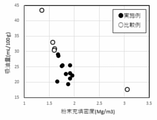
- the sphericity is a physical parameter that reflects the degree of particle gap between secondary particles. This is because, if the particle size distribution is the same, the higher the sphericity, the smaller the particle gap, and as a result, the amount of binder required for electrode fabrication can be minimized. In the present embodiment, since this sphericity is one of the factors that influence the powder packing density, it has been found that it is a requirement for obtaining an appropriate electrode. That is, as shown in FIG.
- the sphericity degree A / B is preferably 0.88 ⁇ A / B ⁇ 1.0. I found that there is.
- FIG. 1 shows an Example by ⁇ and a comparative example by ⁇ . The same applies to FIGS. 2, 3, 4, and 5 below.
- the positive electrode active material according to the present embodiment can control the oil absorption amount within the above-mentioned specified range by using the powder filling density as an index. That is, it has been found that the oil absorption amount of the positive electrode active material can be controlled by the powder filling density.
- the positive electrode active material according to the present embodiment has a powder packing density of 1.65 to 2.20 Mg / m 3 when compressed at 0.01 MPa. It is preferably 1.65 to 2.10 Mg / m 3 , more preferably 1.70 to 2.10 Mg / m 3 , and even more preferably 1.80 to 2.00 Mg / m 3 .
- the powder filling density represents the density when only the positive electrode active material powder is filled in a predetermined space.
- the density at the time of pressurizing 0.01 MPa is defined as the powder filling density so that the variation error of the density measurement can be suppressed and the measurement can be performed with good reproducibility.
- the method for measuring the powder filling density is as follows, and the pressure value of 0.01 MPa set here is suitable for measuring the filled state without destroying the particles.
- the powder filling density is less than 1.65 Mg / m 3 , it means that there are many particle gaps and the amount of binder required for binding at the time of electrode production is large, and the minimum amount of binder required to obtain binding force is required. It will increase. When the amount of the binder added increases, the content of the positive electrode active material contained in the electrode decreases, which is not preferable because the energy density of the positive electrode decreases. Alternatively, when the electrode is manufactured by fixing the amount of the binder in order to secure a predetermined energy density, the binder is insufficient and the binding force is insufficient, which causes cracks and electrode peeling during pressure molding, which is not preferable.
- the particle gap is small and the binder required for electrode fabrication is small, but in reality, the particle size is too coarse, and the voids between the primary particles and the unevenness of the particles are extremely large. This means that the total surface area in contact with the electrolytic solution is small, the contact area between the electrolytic solution and the positive electrode active material is also small, and sufficient discharge capacity cannot be obtained, which is not preferable.
- the method for measuring the powder packing density is described below, but the method is not limited to this.
- the powder filling density is a physical parameter that reflects the amount of particle gaps, and has a correlation with the amount of oil absorption that represents an appropriate amount of binder.
- the present invention is based on JIS K5101-13-1 by setting the powder packing density when the lithium transition metal composite powder is compressed at 0.01 MPa to 1.65 to 2.20 Mg / m 3. It can be said that this is a control method capable of increasing the oil absorption amount of NMP (N-methyl-2-pyrrolidone) per 100 g of the composite oxide powder to 19 to 30 mL / 100 g.
- NMP N-methyl-2-pyrrolidone
- the binder thrown when the electrode is manufactured is intended to bind the positive electrode active materials to each other or the positive electrode active material to the current collector foil.
- the positive electrode active material is generally composed of secondary particles in which a plurality of primary particles are aggregated, and one secondary particle contains pores and voids. Since the binder is absorbed by these pores and voids, the amount of binder added for binding actually increases more than the amount of binder required based on the particle size distribution based on the model without pores and voids. .. Practically, it is preferable to increase the density of the electrodes and increase the energy density per volume.
- the content of the positive electrode active material in the electrode is as high as possible, and the amount of binder added is as small as possible and minimized. For that purpose, it is better to suppress the pores and voids per secondary particle to some extent. Similarly, it is important to reduce the particle gap between the secondary particles in order to minimize the amount of binder added. If the shape of the particles is distorted, the voids between the secondary particles will increase, and the amount of binder added required for electrode fabrication will increase, which is not preferable. Here, it is very important to estimate in advance the amount of binder added required by the positive electrode active material in production control in electrode manufacturing, and the amount of oil absorption is suitable as an index.
- the powder packing density that can be measured more easily is an index that reflects both (i) pores and voids in the secondary particles and (ii) particle gaps between the secondary particles.
- the method for producing a positive electrode active material of the present embodiment includes an inspection step S40 using the powder packing density when the lithium transition metal composite oxide powder is compressed.
- the blending ratio of the positive electrode active material, the conductive material, and the binder is designed. Therefore, it is not preferable to increase the amount of the binder added from the design value according to the properties of the powder of the positive electrode active material, and the positive electrode active material having the property of exhibiting the binding force even with a predetermined amount of the binder added is preferred.
- the oil absorption amount itself was an index for estimating the required amount of the binder, but it was not possible to obtain a design guideline for the positive electrode active material to obtain an appropriate oil absorption amount.
- the present invention it is possible to find a correlation between the oil absorption amount and the powder physical characteristics (powder filling density, sphericity, specific surface area, average particle size, etc.) and provide a guideline for designing a positive electrode active material powder for obtaining an appropriate electrode. can.
- the average particle size of the secondary particles of the positive electrode active material is preferably 6 to 15 ⁇ m. More preferably, it is 7 to 14 ⁇ m.
- the average particle size can be measured with a laser diffraction / scattering type particle size distribution measuring device. When the average particle size is 6 ⁇ m or more, the particle spacing can be appropriately maintained and the electrode density can be improved. If the average particle size is 15 ⁇ m or less, the powder can be laminated in the electrode thickness direction and high filling is possible. Therefore, within the above-mentioned preferable range, the binding force can be maintained even with a predetermined amount of binder added at the time of adjusting the mixture. Further, a plurality of particles can be laminated in the electrode thickness direction, and a good electrode can be manufactured.
- FIG. 3 shows the relationship between the average particle size (D50) and the sphericity.
- the specific surface area of the secondary particles of the positive electrode active material is preferably 0.1 to 0.6 m 2 / g. More preferably, it is 0.1 to 0.4 m 2 / g.
- the specific surface area is measured by the BET method using nitrogen gas adsorption.
- the specific surface area is 0.1 m 2 / g or more, the contact area between the positive electrode active material and the electrolytic solution can be secured when operating as a battery, and a sufficient capacity can be obtained.
- the specific surface area is 0.6 m 2 / g or less, the voids in the secondary particles can be suppressed, the powder packing density can be improved, the oil absorption amount can be reduced, and the electrode peeling can be suppressed.
- the specific surface area is within the above-mentioned preferable range, the contact area between the positive electrode active material and the electrolytic solution can be secured. Further, the fact that the specific surface area is 0.6 m 2 / g or less means that the voids of the secondary particles themselves are small, and the coating can be satisfactorily applied at the time of producing the electrode.
- FIG. 3 also shows the relationship between the specific surface area and the sphericity.
- the positive electrode active material represented by the composition formula (1) it is preferable that the oil absorption amount is 19 to 30 mL / 100 g.
- the sphericity A / B of the shape of the positive electrode active material should be 0.88 ⁇ A / B ⁇ 1.0 as an index of the powder physical properties of the positive electrode active material. Achieved by. Further, it is achieved by setting the powder packing density when the lithium transition metal composite powder is compressed at 0.01 MPa to 1.65 to 2.20 Mg / m 3. Then, the positive electrode active material satisfying this condition is extracted in the inspection step.
- Lithium-ion secondary battery using the positive electrode active material for the lithium ion secondary battery as the positive electrode will be described.
- FIG. 8 is a partial cross-sectional view schematically showing an example of a lithium ion secondary battery.
- the lithium ion secondary battery 100 according to the present embodiment has a bottomed cylindrical battery can 101 accommodating a non-aqueous electrolytic solution and a winding electrode group accommodating the inside of the battery can 101. It includes a 110 and a disk-shaped battery lid 102 that seals an opening at the top of the battery can 101.
- the battery can 101 and the battery lid 102 are formed of, for example, a metal material such as stainless steel or aluminum.
- the positive electrode 111 includes a positive electrode current collector 111a and a positive electrode mixture layer 111b formed on the surface of the positive electrode current collector 111a.
- the negative electrode 112 includes a negative electrode current collector 112a and a negative electrode mixture layer 112b formed on the surface of the negative electrode current collector 112a.
- the positive electrode current collector 111a is formed of, for example, a metal foil such as aluminum or an aluminum alloy, an expanded metal, a punching metal, or the like.
- the metal foil can have a thickness of, for example, 15 ⁇ m or more and 25 ⁇ m or less.
- the positive electrode mixture layer 111b contains the positive electrode active material for the lithium ion secondary battery.
- the positive electrode mixture layer 111b is formed of, for example, a positive electrode mixture in which a positive electrode active material, a conductive material, a binder, and the like are mixed.
- the negative electrode current collector 112a is formed of a metal foil such as copper, copper alloy, nickel, nickel alloy, expanded metal, punching metal, or the like.
- the metal foil can have a thickness of, for example, 7 ⁇ m or more and 10 ⁇ m or less.
- the negative electrode mixture layer 112b contains a negative electrode active material for a lithium ion secondary battery.
- the negative electrode mixture layer 112b is formed of, for example, a negative electrode mixture in which a negative electrode active material is mixed with a conductive material, a binder, or the like.
- an appropriate type used for a general lithium ion secondary battery can be used.
- the conductive material an appropriate type used for a general lithium ion secondary battery can be used.
- the amount of the conductive material can be, for example, 3% by mass or more and 10% by mass or less with respect to the entire mixture.
- the binder an appropriate type used for a general lithium ion secondary battery can be used.
- the amount of the binder can be, for example, 2% by mass or more and 10% by mass or less with respect to the entire mixture.
- the positive electrode 111 can be manufactured according to, for example, a general method for manufacturing an electrode for a lithium ion secondary battery. For example, a mixture preparation step of mixing an active material with a conductive material, a binder, etc. in a solvent to prepare an electrode mixture, and after applying the prepared electrode mixture onto a substrate such as a current collector. It can be manufactured through a mixture coating step of drying to form an electrode mixture layer and a molding step of pressure molding the electrode mixture layer.
- an appropriate mixing device such as a planetary mixer, a dispermixer, or a rotation / revolution mixer can be used.
- the solvent may be, for example, NMP (N-methyl-2-pyrrolidone), water, N, N-dimethylformamide, N, N-dimethylacetamide, methanol, ethanol, propanol, isopropanol, depending on the type of binder.
- Ethylene glycol, diethylene glycol, glycerin, dimethyl sulfoxide, methanol and the like can be used.
- the oil absorption amount of the positive electrode active material itself made of lithium transition metal composite oxide powder it is necessary to set the oil absorption amount of the positive electrode active material itself made of lithium transition metal composite oxide powder within an appropriate range.
- the same solvent it is preferable to use the same solvent as the solvent used in the mixture adjusting step.
- NMP is preferable because of its extremely high solubility, high boiling point and low freezing point, and therefore its versatility.
- the mixture slurry coating step as a means for applying the prepared mixture slurry, for example, an appropriate coating device such as a bar coater, a doctor blade, or a roll transfer machine can be used.
- an appropriate drying device such as a hot air heating device or a radiant heating device can be used.
- an appropriate pressure device such as a roll press can be used as a means for pressure molding the electrode mixture layer.
- the thickness of the positive electrode mixture layer 111b can be, for example, 50 ⁇ m or more and 300 ⁇ m or less.
- the thickness of the negative electrode mixture layer 112b can be, for example, 20 ⁇ m or more and 150 ⁇ m or less.
- the pressure-molded electrode mixture layer can be cut together with the positive electrode current collector, if necessary, to obtain an electrode for a lithium ion secondary battery having a desired shape.
- a positive electrode active material whose oil absorption exceeds a suitable range is applied, the binder becomes insufficient, and the binding between the positive electrode active materials or between the positive electrode active material and the current collector foil becomes insufficient.
- the positive electrode active materials are easily separated from each other due to the load, cracks occur, or the bond between the current collector foil and the positive electrode active material is peeled off and peeled off.
- a positive electrode active material having an oil absorption amount in a suitable range is used, and even with a predetermined binder addition amount, the positive electrode active materials are sufficiently dispersed, or the positive electrode active material and the current collector foil are connected to each other. It is important to maintain the adhesive force and mold. If the binder is not insufficient, the electrode density can be satisfactorily improved in the molding process.
- the wound electrode group 110 is formed by winding a strip-shaped positive electrode 111 and a negative electrode 112 with a separator 113 interposed therebetween.
- the wound electrode group 110 is wound around an axis formed of, for example, polypropylene, polyphenylene sulfide, or the like, and is housed inside the battery can 101.
- the lithium ion secondary battery 100 includes, for example, small power sources such as portable electronic devices and household electric devices, stationary power sources such as power storage devices, uninterruptible power supplies, and power leveling devices, ships, railway vehicles, and hybrids. It can be used for various purposes such as a drive power source for railway vehicles, hybrid vehicles, electric vehicles, and the like.
- Example 1 Production of positive electrode active material Lithium carbonate, nickel hydroxide, cobalt carbonate, manganese carbonate, and titanium oxide are prepared as raw materials, and each raw material is Li: Ni: Co: Mn: Ti in terms of the molar ratio of metal elements. Weighed so as to be 1.03: 0.90: 0.03: 0.05: 0.02, and pure water was added so that the solid content ratio was 30% by mass. Then, wet pulverization (wet mixing) was performed with a pulverizer to prepare a raw material slurry so that the average particle size was less than 0.2 ⁇ m.
- a dispersant of 1.2% by mass was added so that the solid content ratio was 30% by mass.
- the obtained raw material slurry was spray-dried with a nozzle-type spray dryer (manufactured by Okawara Kakoki Co., Ltd., ODL-20 type) to obtain a granulated body having an average particle size of 13 ⁇ m.
- the spray pressure is 0.13 MPa and the spray amount is 260 g / min.
- the dried granules were heat-treated to obtain a lithium transition metal composite oxide.
- the granulated body was heat-treated in a continuous transfer furnace at 400 ° C. for 5 hours in an air atmosphere to obtain a first precursor.
- the first precursor was heat-treated (temporarily fired) at 700 ° C. for 20 hours in an oxygen stream in a firing furnace replaced with an oxygen gas atmosphere to obtain a second precursor.
- the second precursor was heat-treated (main calcination) at 840 ° C. for 10 hours in an oxygen stream in a calcination furnace replaced with an oxygen gas atmosphere. After that, the temperature is lowered to 740 ° C. at 5 ° C./min and held at 740 ° C.
- the temperature lowering rate from 740 ° C. to 700 ° C. is adjusted to 5 ° C./min, and the temperature is in the temperature range of 800 ° C. to 700 ° C.
- the holding time was set to 4.3 hours (annealing treatment). From the above, a lithium transition metal composite oxide was obtained.
- the average composition of the particles of the lithium transition metal composite oxide can be confirmed by high frequency inductively coupled plasma (ICP), atomic absorption spectroscopy (AAS), or the like.
- the lithium transition metal composite oxide obtained as described above was classified using a sieve having an opening of 45 ⁇ m.
- the manufacturing conditions are shown in Table 1.
- the oil absorption of the powder sample was measured according to JIS K5101-13-1, and NMP (N-methylpyrrolidone) was used as the solvent. Weigh 5.0 g of powder sample and place it in a mountain shape on a flat vat. NMP is sucked up with a polydropper (2 mL volume) and the mass is measured. Next, the powder sample is kneaded with a spatula while dropping NMP, and the dropping and kneading are continued until the powder sample becomes clay-like as a whole.
- NMP N-methylpyrrolidone
- the powder filling density of the calcined powder was measured using an autograph. First, 1.0 g of calcined powder was put into a cavity of 7 mm ⁇ 7 mm square, set in an autograph device, and a load was applied from a test force of 0 to over 500 N at a speed of 1 mm / min. The pressure applied to the calcined powder calculated from the cross-sectional area of the cavity was 0.002 MPa to more than 10 MPa. The stroke length when a load was applied was measured every 0.1 seconds, and the powder filling density for each pressure was calculated. Then, the powder filling density at 0.01 MPa was read and used as the powder filling density of the calcined powder. The measurement results are shown in Table 2.
- the fired powder is photographed with a scanning electron microscope (SEM) at a magnification of 1000 times, and the particles 20 having a particle size in the range of D50 ⁇ 0.5 to D50 ⁇ 2.0 based on the average particle size D50 from this SEM photograph.
- Individuals were extracted and the short axis A and the long axis B were measured, respectively.
- the short axis A is the diameter of the circle inscribed in the particle image
- the long axis B is the diameter of the circle circumscribed in the particle image.
- the A / B of 20 particles was averaged to obtain the sphericity of the sample.
- the measurement results are shown in Table 2.
- the average particle size (D50) of the secondary particles of the calcined powder of the positive electrode active material was measured by a laser diffraction type particle size distribution measuring device.
- the specific surface area was measured by the BET method using gas adsorption using an automatic specific surface area measuring device. The measurement results are shown in Table 2.
- a positive electrode (electrode) for a lithium ion secondary battery was manufactured using the synthesized positive electrode active material.
- the obtained positive electrode active material, a carbon-based conductive material, and a binder previously dissolved in NMP (N-methyl-2-pyrrolidone) were mixed so as to have a mass ratio of 96: 2: 2.
- NMP N-methyl-2-pyrrolidone
- the mixture slurry obtained by mixing while adding NMP so as to have a predetermined viscosity is applied to both sides of the positive electrode current collector foil of an aluminum foil having a thickness of 15 ⁇ m so that the coating amount is 46 mg / cm 2. did.
- the mixture slurry applied to the positive electrode current collector was heat-treated at 120 ° C., and the solvent was distilled off to form a positive electrode mixture layer. Then, the positive electrode mixture layer was pressure-molded 5 times by hot pressing and punched to 25 mm ⁇ 41 mm to obtain a positive electrode.
- Example 2 Aluminum oxide powder is used as the Al raw material, and each raw material has a molar ratio of metal elements of Li: Ni: Co: Mn: Al: Ti of 1.03: 0.88: 0.03: 0.05: 0.01.
- a positive electrode active material was synthesized and evaluated in the same manner.
- Example 3 Each raw material was weighed in the same manner as in Example 2 except that lithium hydroxide was used as the Li raw material. Next, only the raw materials excluding lithium hydroxide were wet-pulverized so as to have a solid content ratio of 18% by mass, and granulated bodies were obtained by a spray dryer in the same manner as in Example 2. Since the solid content ratio during wet pulverization was small, no dispersant for thickening measures was added. This granulated product was dehydrated and heat-treated at 600 ° C. to obtain a first precursor from a hydroxide as an oxide.
- a predetermined amount of lithium hydroxide corresponding to the molar ratio of the metal element initially set was added to the obtained first precursor, and the mixture was dry-mixed with a V-type mixer to obtain a raw material mixed powder.
- heat treatment temporary firing
- main firing is performed in the same manner as in Example 2 to obtain a positive electrode.
- the active material was synthesized. Moreover, it was evaluated in the same manner.
- Example 4 A second precursor was obtained in the same manner as in Example 2 except that the solid content ratio at the time of wet grinding was 40% by mass (2.0% by mass of the dispersant), and the heat treatment temperature was 840 ° C. as in Example 1. As a positive electrode active material was synthesized. Moreover, it was evaluated in the same manner.
- Example 5 Each raw material is weighed so that Li: Ni: Co: Mn: Al: Ti is 1.03: 0.90: 0.03: 0.01: 0.03: 0.03 in terms of the molar ratio of metal elements.
- the positive electrode active material was synthesized in the same manner as in Example 3 except that the heat treatment conditions were changed to 800 ° C. Moreover, it was evaluated in the same manner.
- Examples 6 to 11 and Comparative Example 5 Each raw material was weighed so that Li: Ni: Co: Al: Ti had a molar ratio of metal elements of 1.03: 0.92: 0.03: 0.02: 0.03, and heat treatment.
- a positive electrode active material was synthesized in the same manner as in Example 3 except that the conditions were changed to 780 ° C. However, the conditions of the temporary firing stage and the annealing treatment were changed as appropriate. The evaluation was performed in the same manner.
- Example 1 The positive electrode active material was synthesized by the same method as in Example 1 except that the solid content ratio at the time of wet pulverization was set to 50% by mass. Moreover, it was evaluated in the same manner.
- Example 2 The positive electrode active material was synthesized in the same manner as in Example 2 except that the solid content ratio at the time of wet pulverization was 50% by mass. Moreover, it was evaluated in the same manner.
- Example 3 The positive electrode active material was synthesized in the same manner as in Example 2 except that the main firing temperature was set to 800 ° C. Moreover, it was evaluated in the same manner.
- Example 4 The positive electrode active material was synthesized in the same manner as in Example 2 except that the solid content ratio at the time of wet pulverization was 50% by mass and the main firing temperature was 810 ° C. Moreover, it was evaluated in the same manner.
- composition of positive electrode active material synthesized in each Example and Comparative Example Composition of positive electrode active material synthesized in each Example and Comparative Example, slurry solid content ratio, amount of dispersant added, main firing temperature, and powder physical characteristics (average particle size, specific surface area, sphericality, powder at 0.01 MPa)
- the packing density, oil absorption), and the coatability of the electrodes are shown in Tables 1 and 2.
- a lithium ion secondary battery was produced using the synthesized positive electrode active material as the material of the positive electrode, and the lithium ion secondary battery was discharged. I asked for the capacity.
- the prepared positive electrode active material, the carbon-based conductive material, and the binder previously dissolved in N-methyl-2-pyrrolidone (NMP) are mixed in a mass ratio of 92.5: 5: 2.5. It was mixed so as to be. Then, the uniformly mixed positive electrode mixture slurry was applied onto a positive electrode current collector of an aluminum foil having a thickness of 20 ⁇ m so that the coating amount was 10 mg / cm 2 .
- the positive electrode mixture slurry applied to the positive electrode current collector was heat-treated at 120 ° C., and the solvent was distilled off to form a positive electrode mixture layer. Then, the positive electrode mixture layer was pressure-molded by a hot press and punched into a circular shape having a diameter of 15 mm to obtain a positive electrode.
- a lithium ion secondary battery was manufactured using the prepared positive electrode, negative electrode, and separator.
- the negative electrode metallic lithium punched into a circular shape having a diameter of 16 mm was used.
- the separator a polypropylene porous separator having a thickness of 30 ⁇ m was used.
- the positive electrode and the negative electrode were opposed to each other in the non-aqueous electrolytic solution via the separator, and the lithium ion secondary battery was assembled.
- the non-aqueous electrolytic solution a solution in which LiPF 6 was dissolved in a solvent in which ethylene carbonate and dimethyl carbonate were mixed so as to have a volume ratio of 3: 7 and LiPF 6 was dissolved so as to be 1.0 mol / L was used.
- the prepared lithium ion secondary battery was charged in an environment of 25 ° C. with a constant current / constant voltage of 40 A / kg and an upper limit potential of 4.3 V based on the mass of the positive electrode mixture. Then, the battery was discharged to a lower limit potential of 2.5 V at a constant current of 40 A / kg based on the mass of the positive electrode mixture, and the discharge capacity (initial capacity) was measured. The results are shown in Table 2.
- Comparative Example 3 The firing temperature of Comparative Example 3 was lower than that of Example 2. Therefore, since the specific surface area is large and the average particle size is small, the sphericity is as high as 0.90, but the powder packing density is as small as 1.56 Mg / m 3. It can be judged that this is because voids remain in the secondary particles due to low-temperature firing, the powder packing density does not improve even if the sphericity is high, and the oil absorption amount increases to 33 mL / 100 g. As a result, coatability is not possible.
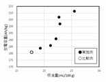
- FIG. 5 shows the relationship between the discharge capacity and the oil absorption amount, and it can be seen that there is a correlation between the oil absorption amount and the discharge capacity.
- the oil absorption amount was 19 to 26 mL / 100 g, whereas the oil absorption amount in Comparative Example 5 was reduced to 18 mL / 100 g.
- the discharge capacity has decreased from 184 Ah / kg to 211 Ah / kg to 181 Ah / kg.
- the oil absorption amount is 23 to 26 mL.
- a higher discharge capacity of 202 Ah / kg to 211 Ah / kg was obtained.
- the oil absorption amount is 19 to 30 mL / 100 g, the capacity is high and the coatability is good, and the preferable range of this oil absorption amount is the powder packing density at 0.01 MPa. Is achieved when is 1.65 to 2.20 Mg / m 3. It can be seen that the specific surface area is preferably 0.1 to 0.6 m 2 / g and the average particle size is preferably 6 to 15 ⁇ m in order to set the powder packing density in a suitable range.
Landscapes
- Chemical & Material Sciences (AREA)
- Chemical Kinetics & Catalysis (AREA)
- Electrochemistry (AREA)
- General Chemical & Material Sciences (AREA)
- Engineering & Computer Science (AREA)
- Inorganic Chemistry (AREA)
- Materials Engineering (AREA)
- Organic Chemistry (AREA)
- Manufacturing & Machinery (AREA)
- Battery Electrode And Active Subsutance (AREA)
Priority Applications (5)
| Application Number | Priority Date | Filing Date | Title |
|---|---|---|---|
| EP21842058.6A EP4184614A4 (en) | 2020-07-14 | 2021-07-07 | POSITIVE ELECTRODE ACTIVE MATERIAL FOR LITHIUM-ION SECONDARY BATTERY AND LITHIUM-ION SECONDARY BATTERY THEREOF |
| JP2022508924A JP7068637B1 (ja) | 2020-07-14 | 2021-07-07 | リチウムイオン二次電池用正極活物質、及びこれを用いたリチウムイオン二次電池 |
| KR1020237000095A KR102933429B1 (ko) | 2020-07-14 | 2021-07-07 | 리튬 이온 이차 전지용 양극 활물질, 및 이를 이용한 리튬 이온 이차 전지 |
| US18/014,744 US20230282819A1 (en) | 2020-07-14 | 2021-07-07 | Positive electrode active material for lithium ion secondary battery, and lithium ion secondary battery in which same is used |
| CN202180049620.2A CN115836410A (zh) | 2020-07-14 | 2021-07-07 | 锂离子二次电池用正极活性物质、及使用其的锂离子二次电池 |
Applications Claiming Priority (2)
| Application Number | Priority Date | Filing Date | Title |
|---|---|---|---|
| JP2020-120366 | 2020-07-14 | ||
| JP2020120366 | 2020-07-14 |
Publications (1)
| Publication Number | Publication Date |
|---|---|
| WO2022014449A1 true WO2022014449A1 (ja) | 2022-01-20 |
Family
ID=79554786
Family Applications (1)
| Application Number | Title | Priority Date | Filing Date |
|---|---|---|---|
| PCT/JP2021/025695 Ceased WO2022014449A1 (ja) | 2020-07-14 | 2021-07-07 | リチウムイオン二次電池用正極活物質、及びこれを用いたリチウムイオン二次電池 |
Country Status (6)
| Country | Link |
|---|---|
| US (1) | US20230282819A1 (https=) |
| EP (1) | EP4184614A4 (https=) |
| JP (1) | JP7068637B1 (https=) |
| KR (1) | KR102933429B1 (https=) |
| CN (1) | CN115836410A (https=) |
| WO (1) | WO2022014449A1 (https=) |
Cited By (1)
| Publication number | Priority date | Publication date | Assignee | Title |
|---|---|---|---|---|
| EP4418342A1 (en) * | 2023-02-14 | 2024-08-21 | Toyota Jidosha Kabushiki Kaisha | Non-aqueous electrolyte secondary battery |
Families Citing this family (2)
| Publication number | Priority date | Publication date | Assignee | Title |
|---|---|---|---|---|
| KR102861561B1 (ko) | 2024-02-28 | 2025-09-18 | 서울대학교산학협력단 | 3d 자세 예측 장치 및 방법 |
| US20250272871A1 (en) | 2024-02-28 | 2025-08-28 | Seoul National University R&Db Foundation | Apparatus and method for predicting three-dimensional pose |
Citations (4)
| Publication number | Priority date | Publication date | Assignee | Title |
|---|---|---|---|---|
| JP2001192208A (ja) * | 1999-06-03 | 2001-07-17 | Titan Kogyo Kk | リチウムチタン複合酸化物及びその製造方法、並びにその用途 |
| JP2005285606A (ja) | 2004-03-30 | 2005-10-13 | Matsushita Electric Ind Co Ltd | 正極活物質及びその評価方法並びに非水電解質二次電池 |
| JP2008174444A (ja) * | 2006-12-22 | 2008-07-31 | Matsushita Electric Ind Co Ltd | ニッケル水酸化物、非水電解質二次電池用正極活物質の製造方法、非水電解質二次電池用電極および非水電解質二次電池 |
| WO2020241804A1 (ja) * | 2019-05-31 | 2020-12-03 | 住友金属鉱山株式会社 | リチウムイオン二次電池用正極活物質前駆体、リチウムイオン二次電池用正極活物質、リチウムイオン二次電池用正極活物質前駆体の製造方法、リチウムイオン二次電池用正極活物質の製造方法、リチウムイオン二次電池 |
Family Cites Families (10)
| Publication number | Priority date | Publication date | Assignee | Title |
|---|---|---|---|---|
| KR101058187B1 (ko) | 2008-12-05 | 2011-08-22 | 주식회사 에스에프에이 | 기판 보관용 카세트 시스템 |
| JP5737596B2 (ja) * | 2010-10-15 | 2015-06-17 | トヨタ自動車株式会社 | 二次電池 |
| WO2012147812A1 (ja) * | 2011-04-28 | 2012-11-01 | 株式会社トクヤマ | 金属酸化物粉末及びその製造方法 |
| CN103636035B (zh) * | 2011-06-24 | 2016-05-04 | 旭硝子株式会社 | 锂离子二次电池用正极活性物质的制造方法 |
| JP2013055000A (ja) * | 2011-09-06 | 2013-03-21 | Mitsubishi Chemicals Corp | リチウム二次電池正極材料用リチウム遷移金属系化合物粉体及びその製造方法、並びにそれを用いたリチウム二次電池用正極及びリチウム二次電池 |
| JP6288340B1 (ja) * | 2017-03-24 | 2018-03-07 | 住友大阪セメント株式会社 | リチウムイオン二次電池用電極材料、及びリチウムイオン二次電池 |
| CN107275620A (zh) * | 2017-07-06 | 2017-10-20 | 广州朝锂新能源科技有限公司 | 一种掺杂包覆改性锂离子电池层状富镍正极材料及其制备方法 |
| WO2019131779A1 (ja) * | 2017-12-27 | 2019-07-04 | 日立金属株式会社 | リチウムイオン二次電池用正極活物質及びリチウムイオン二次電池用正極活物質の製造方法、並びにリチウムイオン二次電池 |
| CN110676451B (zh) * | 2019-12-04 | 2020-04-14 | 湖南省正源储能材料与器件研究所 | 一种晶粒径向生长排布的中空球形正极材料及其制备方法 |
| WO2021186949A1 (ja) * | 2020-03-18 | 2021-09-23 | 三洋電機株式会社 | 非水電解質二次電池 |
-
2021
- 2021-07-07 KR KR1020237000095A patent/KR102933429B1/ko active Active
- 2021-07-07 CN CN202180049620.2A patent/CN115836410A/zh active Pending
- 2021-07-07 EP EP21842058.6A patent/EP4184614A4/en active Pending
- 2021-07-07 US US18/014,744 patent/US20230282819A1/en active Pending
- 2021-07-07 WO PCT/JP2021/025695 patent/WO2022014449A1/ja not_active Ceased
- 2021-07-07 JP JP2022508924A patent/JP7068637B1/ja active Active
Patent Citations (4)
| Publication number | Priority date | Publication date | Assignee | Title |
|---|---|---|---|---|
| JP2001192208A (ja) * | 1999-06-03 | 2001-07-17 | Titan Kogyo Kk | リチウムチタン複合酸化物及びその製造方法、並びにその用途 |
| JP2005285606A (ja) | 2004-03-30 | 2005-10-13 | Matsushita Electric Ind Co Ltd | 正極活物質及びその評価方法並びに非水電解質二次電池 |
| JP2008174444A (ja) * | 2006-12-22 | 2008-07-31 | Matsushita Electric Ind Co Ltd | ニッケル水酸化物、非水電解質二次電池用正極活物質の製造方法、非水電解質二次電池用電極および非水電解質二次電池 |
| WO2020241804A1 (ja) * | 2019-05-31 | 2020-12-03 | 住友金属鉱山株式会社 | リチウムイオン二次電池用正極活物質前駆体、リチウムイオン二次電池用正極活物質、リチウムイオン二次電池用正極活物質前駆体の製造方法、リチウムイオン二次電池用正極活物質の製造方法、リチウムイオン二次電池 |
Non-Patent Citations (1)
| Title |
|---|
| See also references of EP4184614A4 |
Cited By (2)
| Publication number | Priority date | Publication date | Assignee | Title |
|---|---|---|---|---|
| EP4418342A1 (en) * | 2023-02-14 | 2024-08-21 | Toyota Jidosha Kabushiki Kaisha | Non-aqueous electrolyte secondary battery |
| JP2024115038A (ja) * | 2023-02-14 | 2024-08-26 | トヨタ自動車株式会社 | 非水電解質二次電池 |
Also Published As
| Publication number | Publication date |
|---|---|
| JP7068637B1 (ja) | 2022-05-17 |
| KR102933429B1 (ko) | 2026-03-03 |
| JPWO2022014449A1 (https=) | 2022-01-20 |
| KR20230066309A (ko) | 2023-05-15 |
| US20230282819A1 (en) | 2023-09-07 |
| EP4184614A1 (en) | 2023-05-24 |
| CN115836410A (zh) | 2023-03-21 |
| EP4184614A4 (en) | 2024-07-17 |
Similar Documents
| Publication | Publication Date | Title |
|---|---|---|
| JP7722435B2 (ja) | 遷移金属含有複合水酸化物とその製造方法、非水電解質二次電池用正極活物質とその製造方法、および非水電解質二次電池 | |
| JP5971109B2 (ja) | ニッケル複合水酸化物とその製造方法、非水系電解質二次電池用正極活物質とその製造方法、および非水系電解質二次電池 | |
| EP2157638B1 (en) | Positive electrode active material sintered body for a lithium ion secondary battery | |
| JP4894969B1 (ja) | ニッケルマンガン複合水酸化物粒子とその製造方法、非水系電解質二次電池用正極活物質とその製造方法、ならびに、非水系電解質二次電池 | |
| JP4915488B1 (ja) | ニッケルマンガン複合水酸化物粒子とその製造方法、非水系電解質二次電池用正極活物質とその製造方法、および非水系電解質二次電池 | |
| JP6986211B2 (ja) | リチウムイオン二次電池用正極活物質、及びその製造方法、並びにリチウムイオン二次電池 | |
| JP6196175B2 (ja) | リチウム二次電池用正極活物質の製造方法及びそれに用いられる活物質前駆体粉末 | |
| EP1491504B1 (en) | Lithium manganese composite oxide granular secondary particle, method for production thereof and use thereof | |
| WO2017221554A1 (ja) | リチウムイオン二次電池用正極活物質の製造方法及びリチウムイオン二次電池用正極活物質、並びにリチウムイオン二次電池 | |
| JP7068637B1 (ja) | リチウムイオン二次電池用正極活物質、及びこれを用いたリチウムイオン二次電池 | |
| JP5830179B2 (ja) | リチウム二次電池用正極活物質の製造方法及びそれに用いられる活物質前駆体粉末 | |
| JP6544579B2 (ja) | タングステン酸リチウムの製造方法、およびタングステン酸リチウムを用いた非水系電解質二次電池用正極活物質の製造方法 | |
| JP2010505732A (ja) | 化合物粉体、その製造方法およびリチウム二次電池へのその使用 | |
| JP5494199B2 (ja) | 非水系電解質二次電池用正極活物質およびその製造方法、ならびに該正極活物質を用いた非水系電解質二次電池 | |
| KR20130097733A (ko) | 티탄산리튬 입자 분말 및 그의 제조 방법, Mg 함유 티탄산리튬 입자 분말 및 그의 제조법, 비수전해질 이차 전지용 부극 활성 물질 입자 분말 및 비수전해질 이차 전지 | |
| JP7664896B2 (ja) | 高強度リチウムイオン二次電池用正極活物質、及び、該正極活物質を用いたリチウムイオン二次電池 | |
| WO2014061579A1 (ja) | リチウム二次電池用正極活物質の製造方法及びそれに用いられる活物質前駆体粉末 | |
| US20150180025A1 (en) | Lithium Metal Complex Oxide | |
| JP7452569B2 (ja) | 非水系電解質二次電池用正極活物質 | |
| CN108028375B (zh) | 正极活性物质、正极、以及锂离子二次电池 | |
| WO2003083969A1 (en) | Positive electrode material for lithium secondary cell and secondary cell using the same, and method for producing positive electrode material for lithium secondary cell | |
| WO2020261962A1 (ja) | リチウムイオン二次電池用正極活物質およびその製造方法、並びに、リチウムイオン二次電池 | |
| JP7618991B2 (ja) | リチウムイオン二次電池用正極活物質、及びその製造方法、並びにリチウムイオン二次電池 | |
| JP2021005548A (ja) | リチウムイオン二次電池用正極活物質およびその製造方法、並びに、リチウムイオン二次電池 | |
| JP7318842B1 (ja) | リチウムイオン二次電池用正極活物質およびリチウムイオン二次電池 |
Legal Events
| Date | Code | Title | Description |
|---|---|---|---|
| ENP | Entry into the national phase |
Ref document number: 2022508924 Country of ref document: JP Kind code of ref document: A |
|
| 121 | Ep: the epo has been informed by wipo that ep was designated in this application |
Ref document number: 21842058 Country of ref document: EP Kind code of ref document: A1 |
|
| NENP | Non-entry into the national phase |
Ref country code: DE |
|
| ENP | Entry into the national phase |
Ref document number: 2021842058 Country of ref document: EP Effective date: 20230214 |