WO2022011073A1 - Anti-glare substrate for a display article including a textured region with primary surface features and secondary surface features imparting a surface roughness that increases surface scattering - Google Patents
Anti-glare substrate for a display article including a textured region with primary surface features and secondary surface features imparting a surface roughness that increases surface scattering Download PDFInfo
- Publication number
- WO2022011073A1 WO2022011073A1 PCT/US2021/040775 US2021040775W WO2022011073A1 WO 2022011073 A1 WO2022011073 A1 WO 2022011073A1 US 2021040775 W US2021040775 W US 2021040775W WO 2022011073 A1 WO2022011073 A1 WO 2022011073A1
- Authority
- WO
- WIPO (PCT)
- Prior art keywords
- surface features
- primary surface
- substrate
- textured region
- primary
- Prior art date
- Legal status (The legal status is an assumption and is not a legal conclusion. Google has not performed a legal analysis and makes no representation as to the accuracy of the status listed.)
- Ceased
Links
Classifications
-
- C—CHEMISTRY; METALLURGY
- C03—GLASS; MINERAL OR SLAG WOOL
- C03C—CHEMICAL COMPOSITION OF GLASSES, GLAZES OR VITREOUS ENAMELS; SURFACE TREATMENT OF GLASS; SURFACE TREATMENT OF FIBRES OR FILAMENTS MADE FROM GLASS, MINERALS OR SLAGS; JOINING GLASS TO GLASS OR OTHER MATERIALS
- C03C15/00—Surface treatment of glass, not in the form of fibres or filaments, by etching
-
- G—PHYSICS
- G02—OPTICS
- G02B—OPTICAL ELEMENTS, SYSTEMS OR APPARATUS
- G02B1/00—Optical elements characterised by the material of which they are made; Optical coatings for optical elements
- G02B1/10—Optical coatings produced by application to, or surface treatment of, optical elements
- G02B1/11—Anti-reflection coatings
- G02B1/113—Anti-reflection coatings using inorganic layer materials only
- G02B1/115—Multilayers
-
- G—PHYSICS
- G02—OPTICS
- G02B—OPTICAL ELEMENTS, SYSTEMS OR APPARATUS
- G02B1/00—Optical elements characterised by the material of which they are made; Optical coatings for optical elements
- G02B1/10—Optical coatings produced by application to, or surface treatment of, optical elements
- G02B1/11—Anti-reflection coatings
-
- C—CHEMISTRY; METALLURGY
- C03—GLASS; MINERAL OR SLAG WOOL
- C03C—CHEMICAL COMPOSITION OF GLASSES, GLAZES OR VITREOUS ENAMELS; SURFACE TREATMENT OF GLASS; SURFACE TREATMENT OF FIBRES OR FILAMENTS MADE FROM GLASS, MINERALS OR SLAGS; JOINING GLASS TO GLASS OR OTHER MATERIALS
- C03C17/00—Surface treatment of glass, not in the form of fibres or filaments, by coating
- C03C17/22—Surface treatment of glass, not in the form of fibres or filaments, by coating with other inorganic material
- C03C17/225—Nitrides
-
- C—CHEMISTRY; METALLURGY
- C03—GLASS; MINERAL OR SLAG WOOL
- C03C—CHEMICAL COMPOSITION OF GLASSES, GLAZES OR VITREOUS ENAMELS; SURFACE TREATMENT OF GLASS; SURFACE TREATMENT OF FIBRES OR FILAMENTS MADE FROM GLASS, MINERALS OR SLAGS; JOINING GLASS TO GLASS OR OTHER MATERIALS
- C03C17/00—Surface treatment of glass, not in the form of fibres or filaments, by coating
- C03C17/34—Surface treatment of glass, not in the form of fibres or filaments, by coating with at least two coatings having different compositions
- C03C17/3411—Surface treatment of glass, not in the form of fibres or filaments, by coating with at least two coatings having different compositions with at least two coatings of inorganic materials
- C03C17/3429—Surface treatment of glass, not in the form of fibres or filaments, by coating with at least two coatings having different compositions with at least two coatings of inorganic materials at least one of the coatings being a non-oxide coating
- C03C17/3435—Surface treatment of glass, not in the form of fibres or filaments, by coating with at least two coatings having different compositions with at least two coatings of inorganic materials at least one of the coatings being a non-oxide coating comprising a nitride, oxynitride, boronitride or carbonitride
-
- C—CHEMISTRY; METALLURGY
- C03—GLASS; MINERAL OR SLAG WOOL
- C03C—CHEMICAL COMPOSITION OF GLASSES, GLAZES OR VITREOUS ENAMELS; SURFACE TREATMENT OF GLASS; SURFACE TREATMENT OF FIBRES OR FILAMENTS MADE FROM GLASS, MINERALS OR SLAGS; JOINING GLASS TO GLASS OR OTHER MATERIALS
- C03C21/00—Treatment of glass, not in the form of fibres or filaments, by diffusing ions or metals in the surface
- C03C21/001—Treatment of glass, not in the form of fibres or filaments, by diffusing ions or metals in the surface in liquid phase, e.g. molten salts, solutions
- C03C21/002—Treatment of glass, not in the form of fibres or filaments, by diffusing ions or metals in the surface in liquid phase, e.g. molten salts, solutions to perform ion-exchange between alkali ions
-
- C—CHEMISTRY; METALLURGY
- C23—COATING METALLIC MATERIAL; COATING MATERIAL WITH METALLIC MATERIAL; CHEMICAL SURFACE TREATMENT; DIFFUSION TREATMENT OF METALLIC MATERIAL; COATING BY VACUUM EVAPORATION, BY SPUTTERING, BY ION IMPLANTATION OR BY CHEMICAL VAPOUR DEPOSITION, IN GENERAL; INHIBITING CORROSION OF METALLIC MATERIAL OR INCRUSTATION IN GENERAL
- C23C—COATING METALLIC MATERIAL; COATING MATERIAL WITH METALLIC MATERIAL; SURFACE TREATMENT OF METALLIC MATERIAL BY DIFFUSION INTO THE SURFACE, BY CHEMICAL CONVERSION OR SUBSTITUTION; COATING BY VACUUM EVAPORATION, BY SPUTTERING, BY ION IMPLANTATION OR BY CHEMICAL VAPOUR DEPOSITION, IN GENERAL
- C23C14/00—Coating by vacuum evaporation, by sputtering or by ion implantation of the coating forming material
- C23C14/02—Pretreatment of the material to be coated
- C23C14/021—Cleaning or etching treatments
-
- C—CHEMISTRY; METALLURGY
- C23—COATING METALLIC MATERIAL; COATING MATERIAL WITH METALLIC MATERIAL; CHEMICAL SURFACE TREATMENT; DIFFUSION TREATMENT OF METALLIC MATERIAL; COATING BY VACUUM EVAPORATION, BY SPUTTERING, BY ION IMPLANTATION OR BY CHEMICAL VAPOUR DEPOSITION, IN GENERAL; INHIBITING CORROSION OF METALLIC MATERIAL OR INCRUSTATION IN GENERAL
- C23C—COATING METALLIC MATERIAL; COATING MATERIAL WITH METALLIC MATERIAL; SURFACE TREATMENT OF METALLIC MATERIAL BY DIFFUSION INTO THE SURFACE, BY CHEMICAL CONVERSION OR SUBSTITUTION; COATING BY VACUUM EVAPORATION, BY SPUTTERING, BY ION IMPLANTATION OR BY CHEMICAL VAPOUR DEPOSITION, IN GENERAL
- C23C14/00—Coating by vacuum evaporation, by sputtering or by ion implantation of the coating forming material
- C23C14/04—Coating on selected surface areas, e.g. using masks
- C23C14/042—Coating on selected surface areas, e.g. using masks using masks
-
- C—CHEMISTRY; METALLURGY
- C23—COATING METALLIC MATERIAL; COATING MATERIAL WITH METALLIC MATERIAL; CHEMICAL SURFACE TREATMENT; DIFFUSION TREATMENT OF METALLIC MATERIAL; COATING BY VACUUM EVAPORATION, BY SPUTTERING, BY ION IMPLANTATION OR BY CHEMICAL VAPOUR DEPOSITION, IN GENERAL; INHIBITING CORROSION OF METALLIC MATERIAL OR INCRUSTATION IN GENERAL
- C23C—COATING METALLIC MATERIAL; COATING MATERIAL WITH METALLIC MATERIAL; SURFACE TREATMENT OF METALLIC MATERIAL BY DIFFUSION INTO THE SURFACE, BY CHEMICAL CONVERSION OR SUBSTITUTION; COATING BY VACUUM EVAPORATION, BY SPUTTERING, BY ION IMPLANTATION OR BY CHEMICAL VAPOUR DEPOSITION, IN GENERAL
- C23C16/00—Chemical coating by decomposition of gaseous compounds, without leaving reaction products of surface material in the coating, i.e. chemical vapour deposition [CVD] processes
- C23C16/02—Pretreatment of the material to be coated
- C23C16/0227—Pretreatment of the material to be coated by cleaning or etching
-
- C—CHEMISTRY; METALLURGY
- C23—COATING METALLIC MATERIAL; COATING MATERIAL WITH METALLIC MATERIAL; CHEMICAL SURFACE TREATMENT; DIFFUSION TREATMENT OF METALLIC MATERIAL; COATING BY VACUUM EVAPORATION, BY SPUTTERING, BY ION IMPLANTATION OR BY CHEMICAL VAPOUR DEPOSITION, IN GENERAL; INHIBITING CORROSION OF METALLIC MATERIAL OR INCRUSTATION IN GENERAL
- C23C—COATING METALLIC MATERIAL; COATING MATERIAL WITH METALLIC MATERIAL; SURFACE TREATMENT OF METALLIC MATERIAL BY DIFFUSION INTO THE SURFACE, BY CHEMICAL CONVERSION OR SUBSTITUTION; COATING BY VACUUM EVAPORATION, BY SPUTTERING, BY ION IMPLANTATION OR BY CHEMICAL VAPOUR DEPOSITION, IN GENERAL
- C23C16/00—Chemical coating by decomposition of gaseous compounds, without leaving reaction products of surface material in the coating, i.e. chemical vapour deposition [CVD] processes
- C23C16/04—Coating on selected surface areas, e.g. using masks
- C23C16/042—Coating on selected surface areas, e.g. using masks using masks
-
- G—PHYSICS
- G02—OPTICS
- G02B—OPTICAL ELEMENTS, SYSTEMS OR APPARATUS
- G02B1/00—Optical elements characterised by the material of which they are made; Optical coatings for optical elements
- G02B1/10—Optical coatings produced by application to, or surface treatment of, optical elements
- G02B1/11—Anti-reflection coatings
- G02B1/118—Anti-reflection coatings having sub-optical wavelength surface structures designed to provide an enhanced transmittance, e.g. moth-eye structures
-
- G—PHYSICS
- G02—OPTICS
- G02B—OPTICAL ELEMENTS, SYSTEMS OR APPARATUS
- G02B1/00—Optical elements characterised by the material of which they are made; Optical coatings for optical elements
- G02B1/10—Optical coatings produced by application to, or surface treatment of, optical elements
- G02B1/14—Protective coatings, e.g. hard coatings
-
- G—PHYSICS
- G02—OPTICS
- G02B—OPTICAL ELEMENTS, SYSTEMS OR APPARATUS
- G02B27/00—Optical systems or apparatus not provided for by any of the groups G02B1/00 - G02B26/00, G02B30/00
- G02B27/42—Diffraction optics, i.e. systems including a diffractive element being designed for providing a diffractive effect
- G02B27/4205—Diffraction optics, i.e. systems including a diffractive element being designed for providing a diffractive effect having a diffractive optical element [DOE] contributing to image formation, e.g. whereby modulation transfer function MTF or optical aberrations are relevant
-
- G—PHYSICS
- G02—OPTICS
- G02B—OPTICAL ELEMENTS, SYSTEMS OR APPARATUS
- G02B27/00—Optical systems or apparatus not provided for by any of the groups G02B1/00 - G02B26/00, G02B30/00
- G02B27/42—Diffraction optics, i.e. systems including a diffractive element being designed for providing a diffractive effect
- G02B27/4272—Diffraction optics, i.e. systems including a diffractive element being designed for providing a diffractive effect having plural diffractive elements positioned sequentially along the optical path
-
- G—PHYSICS
- G02—OPTICS
- G02B—OPTICAL ELEMENTS, SYSTEMS OR APPARATUS
- G02B5/00—Optical elements other than lenses
- G02B5/02—Diffusing elements; Afocal elements
- G02B5/0205—Diffusing elements; Afocal elements characterised by the diffusing properties
- G02B5/021—Diffusing elements; Afocal elements characterised by the diffusing properties the diffusion taking place at the element's surface, e.g. by means of surface roughening or microprismatic structures
-
- G—PHYSICS
- G02—OPTICS
- G02B—OPTICAL ELEMENTS, SYSTEMS OR APPARATUS
- G02B5/00—Optical elements other than lenses
- G02B5/02—Diffusing elements; Afocal elements
- G02B5/0205—Diffusing elements; Afocal elements characterised by the diffusing properties
- G02B5/021—Diffusing elements; Afocal elements characterised by the diffusing properties the diffusion taking place at the element's surface, e.g. by means of surface roughening or microprismatic structures
- G02B5/0221—Diffusing elements; Afocal elements characterised by the diffusing properties the diffusion taking place at the element's surface, e.g. by means of surface roughening or microprismatic structures the surface having an irregular structure
-
- G—PHYSICS
- G02—OPTICS
- G02B—OPTICAL ELEMENTS, SYSTEMS OR APPARATUS
- G02B5/00—Optical elements other than lenses
- G02B5/02—Diffusing elements; Afocal elements
- G02B5/0268—Diffusing elements; Afocal elements characterized by the fabrication or manufacturing method
-
- G—PHYSICS
- G09—EDUCATION; CRYPTOGRAPHY; DISPLAY; ADVERTISING; SEALS
- G09F—DISPLAYING; ADVERTISING; SIGNS; LABELS OR NAME-PLATES; SEALS
- G09F9/00—Indicating arrangements for variable information in which the information is built-up on a support by selection or combination of individual elements
- G09F9/30—Indicating arrangements for variable information in which the information is built-up on a support by selection or combination of individual elements in which the desired character or characters are formed by combining individual elements
-
- C—CHEMISTRY; METALLURGY
- C03—GLASS; MINERAL OR SLAG WOOL
- C03C—CHEMICAL COMPOSITION OF GLASSES, GLAZES OR VITREOUS ENAMELS; SURFACE TREATMENT OF GLASS; SURFACE TREATMENT OF FIBRES OR FILAMENTS MADE FROM GLASS, MINERALS OR SLAGS; JOINING GLASS TO GLASS OR OTHER MATERIALS
- C03C2204/00—Glasses, glazes or enamels with special properties
- C03C2204/08—Glass having a rough surface
-
- C—CHEMISTRY; METALLURGY
- C03—GLASS; MINERAL OR SLAG WOOL
- C03C—CHEMICAL COMPOSITION OF GLASSES, GLAZES OR VITREOUS ENAMELS; SURFACE TREATMENT OF GLASS; SURFACE TREATMENT OF FIBRES OR FILAMENTS MADE FROM GLASS, MINERALS OR SLAGS; JOINING GLASS TO GLASS OR OTHER MATERIALS
- C03C2217/00—Coatings on glass
- C03C2217/70—Properties of coatings
-
- C—CHEMISTRY; METALLURGY
- C03—GLASS; MINERAL OR SLAG WOOL
- C03C—CHEMICAL COMPOSITION OF GLASSES, GLAZES OR VITREOUS ENAMELS; SURFACE TREATMENT OF GLASS; SURFACE TREATMENT OF FIBRES OR FILAMENTS MADE FROM GLASS, MINERALS OR SLAGS; JOINING GLASS TO GLASS OR OTHER MATERIALS
- C03C2218/00—Methods for coating glass
- C03C2218/10—Deposition methods
- C03C2218/15—Deposition methods from the vapour phase
-
- C—CHEMISTRY; METALLURGY
- C03—GLASS; MINERAL OR SLAG WOOL
- C03C—CHEMICAL COMPOSITION OF GLASSES, GLAZES OR VITREOUS ENAMELS; SURFACE TREATMENT OF GLASS; SURFACE TREATMENT OF FIBRES OR FILAMENTS MADE FROM GLASS, MINERALS OR SLAGS; JOINING GLASS TO GLASS OR OTHER MATERIALS
- C03C2218/00—Methods for coating glass
- C03C2218/10—Deposition methods
- C03C2218/15—Deposition methods from the vapour phase
- C03C2218/152—Deposition methods from the vapour phase by cvd
-
- C—CHEMISTRY; METALLURGY
- C03—GLASS; MINERAL OR SLAG WOOL
- C03C—CHEMICAL COMPOSITION OF GLASSES, GLAZES OR VITREOUS ENAMELS; SURFACE TREATMENT OF GLASS; SURFACE TREATMENT OF FIBRES OR FILAMENTS MADE FROM GLASS, MINERALS OR SLAGS; JOINING GLASS TO GLASS OR OTHER MATERIALS
- C03C2218/00—Methods for coating glass
- C03C2218/10—Deposition methods
- C03C2218/15—Deposition methods from the vapour phase
- C03C2218/152—Deposition methods from the vapour phase by cvd
- C03C2218/153—Deposition methods from the vapour phase by cvd by plasma-enhanced cvd
-
- C—CHEMISTRY; METALLURGY
- C03—GLASS; MINERAL OR SLAG WOOL
- C03C—CHEMICAL COMPOSITION OF GLASSES, GLAZES OR VITREOUS ENAMELS; SURFACE TREATMENT OF GLASS; SURFACE TREATMENT OF FIBRES OR FILAMENTS MADE FROM GLASS, MINERALS OR SLAGS; JOINING GLASS TO GLASS OR OTHER MATERIALS
- C03C2218/00—Methods for coating glass
- C03C2218/10—Deposition methods
- C03C2218/15—Deposition methods from the vapour phase
- C03C2218/154—Deposition methods from the vapour phase by sputtering
- C03C2218/155—Deposition methods from the vapour phase by sputtering by reactive sputtering
-
- C—CHEMISTRY; METALLURGY
- C03—GLASS; MINERAL OR SLAG WOOL
- C03C—CHEMICAL COMPOSITION OF GLASSES, GLAZES OR VITREOUS ENAMELS; SURFACE TREATMENT OF GLASS; SURFACE TREATMENT OF FIBRES OR FILAMENTS MADE FROM GLASS, MINERALS OR SLAGS; JOINING GLASS TO GLASS OR OTHER MATERIALS
- C03C2218/00—Methods for coating glass
- C03C2218/30—Aspects of methods for coating glass not covered above
- C03C2218/34—Masking
-
- C—CHEMISTRY; METALLURGY
- C03—GLASS; MINERAL OR SLAG WOOL
- C03C—CHEMICAL COMPOSITION OF GLASSES, GLAZES OR VITREOUS ENAMELS; SURFACE TREATMENT OF GLASS; SURFACE TREATMENT OF FIBRES OR FILAMENTS MADE FROM GLASS, MINERALS OR SLAGS; JOINING GLASS TO GLASS OR OTHER MATERIALS
- C03C3/00—Glass compositions
- C03C3/04—Glass compositions containing silica
- C03C3/076—Glass compositions containing silica with 40% to 90% silica, by weight
-
- C—CHEMISTRY; METALLURGY
- C03—GLASS; MINERAL OR SLAG WOOL
- C03C—CHEMICAL COMPOSITION OF GLASSES, GLAZES OR VITREOUS ENAMELS; SURFACE TREATMENT OF GLASS; SURFACE TREATMENT OF FIBRES OR FILAMENTS MADE FROM GLASS, MINERALS OR SLAGS; JOINING GLASS TO GLASS OR OTHER MATERIALS
- C03C3/00—Glass compositions
- C03C3/04—Glass compositions containing silica
- C03C3/076—Glass compositions containing silica with 40% to 90% silica, by weight
- C03C3/083—Glass compositions containing silica with 40% to 90% silica, by weight containing aluminium oxide or an iron compound
-
- G—PHYSICS
- G02—OPTICS
- G02B—OPTICAL ELEMENTS, SYSTEMS OR APPARATUS
- G02B2207/00—Coding scheme for general features or characteristics of optical elements and systems of subclass G02B, but not including elements and systems which would be classified in G02B6/00 and subgroups
- G02B2207/101—Nanooptics
Definitions
- ______ (D32630/32632), entitled “TEXTURED REGION OF A SUBSTRATE TO REDUCE SPECULAR REFLECTANCE INCORPORATING SURFACE FEATURES WITH AN ELLIPTICAL PERIMETER OR SEGMENTS THEREOF, AND METHOD OF MAKING THE SAME” and filed on ___; U.S. Patent Application Serial No. ____ (D32647), entitled “DISPLAY ARTICLES WITH DIFFRACTIVE, ANTIGLARE SURFACES AND THIN, DURABLE ANTIREFLECTION COATINGS” and filed on __________; and U.S. Patent Application Serial No.
- ______ (D32623), entitled “DISPLAY ARTICLES WITH DIFFRACTIVE, ANTIGLARE SURFACES AND THIN, DURABLE ANTIREFLECTION COATINGS” and filed on ____.
- the entire disclosures of each of the foregoing U.S. patent applications, publications and patent documents are incorporated herein by reference.
- FIELD OF INVENTION [0003] The disclosure relates to an anti ⁇ glare substrate for display articles where the anti ⁇ glare substrate includes a textured region with primary surface features and secondary surface features imparting a surface roughness that increases surface scattering.
- BACKGROUND [0004] Substrates transparent to visible light are utilized to cover displays of display articles.
- Such display articles include smart phones, tablets, televisions, computer monitors, and the like.
- the displays are often liquid crystal displays, organic light emitting diodes, among others.
- the substrate protects the display, while the transparency of the substrate allows the user of the device to view the display.
- the substrate reflecting ambient light, especially specular reflection reduces the ability of the user to view the display through the substrate. Specular reflection in this context is the mirror ⁇ like reflection of ambient light off the substrate.
- the substrate may reflect visible light reflecting off or emitted by an object in the environment around the device. The visible light reflecting off the substrate reduces the contrast of the light from the display transmitting to the eyes of the user through the substrate.
- Such methods of texturing i.e., sandblasting and liquid etching
- sandblasting and liquid etching generate features on the surface with imprecise and unrepeatable geometry (the features provide the texture).
- the geometry of the textured surface of one substrate formed via sandblasting or liquid etching can never be the same as the geometry of the textured surface of another substrate formed via sandblasting or liquid etching.
- R a surface roughness
- Distinctness ⁇ of ⁇ image which more aptly might be referred to as distinctness ⁇ of ⁇ reflected ⁇ image, is a measure of how distinct an image reflecting off the surface appears. The lower the distinctness ⁇ of ⁇ image, the more the textured surface is diffusely reflecting rather than specularly reflecting. Surface features can magnify various pixels of the display, which distorts the image that the user views. Pixel power deviation, also referred to as "sparkle,” is a quantification of such an effect. The lower the pixel power deviation the better.
- Moiré interference fringes are large scale interference patterns, which, if visible, distort the image that the user sees.
- the textured surface produces no apparent Moiré interference fringes.
- Transmission haze is a measure of how much the textured surface is diffusing the visible light that the display emitted upon transmitting through the substrate. The greater the transmission haze, the less sharp the display appears (i.e., lowered apparent resolution).
- Specular reflection reduction is again a measure of how much of the reflected ambient light off the textured surface is specular. The lower the better.
- Reflection color artifacts are a sort of chromatic aberration where the textured surface diffracts light upon reflection as a function of wavelength ⁇ meaning that the reflected light, although relatively diffuse, appears segmented by color.
- a new approach to providing a textured region of the substrate is needed ⁇ one that is reproducible from substrate ⁇ to ⁇ substrate and one that causes the textured surface to reflect ambient light sufficiently diffusely rather than specularly so as to be "antiglare" (e.g., a low distinctness ⁇ of ⁇ image, low specular reflection) but simultaneously also delivers low pixel power deviation, low transmission haze, and low reflection color artifacts.
- the present disclosure provides a new approach that specifically places primary surface features having a specific geometry throughout a textured region according to a predetermined placement. The primary surface features cause the substrate to reflect rather diffusely and are reproducible from substrate ⁇ to ⁇ substrate because the placement of each primary surface feature is by design.
- secondary surface features are incorporated into the textured region to increase the surface roughness to within a certain range.
- the increased surface roughness imparts surface scattering to the textured region, which generally lowers pixel power deviation and specular reflection, and sometimes distinctness of image too.
- a substrate for a display article comprising: (a) a primary surface; and (b) a textured region on at least a portion of the primary surface; the textured region comprising: (i) primary surface features, each comprising a perimeter parallel to a base ⁇ plane extending through the substrate disposed below the textured region, wherein the perimeter of each of the primary surface features comprises a longest dimension of at least 5 ⁇ m; and (ii) one or more sections each comprising secondary surface features having a surface roughness (R a ) within a range of 5 nm to 100 nm.
- the substrate of the first aspect wherein the primary surface features form a pattern.
- the substrate of any one of the first through second aspects the longest dimension of each of the primary surface features is about the same.
- the substrate of any one of the first through third aspects wherein an arrangement of the surface features reflect a random distribution.
- the substrate of any one of the first through fourth aspects wherein the perimeter of each primary surface features is elliptical.
- the substrate of any one of the first through fourth aspects wherein the perimeter of each primary surface features is circular.
- each primary surface feature provides a surface, and the surface is either concave or convex.
- the substrate of any one of the first through seventh aspects, wherein the textured region further comprises: a surrounding portion into which the primary surface features are set or out of which the primary surface features project.
- the substrate of any one of the first through eighth aspects wherein (i) the primary surface features that are adjacent to one another have perimeters that are separated by a distance within a range of 1 ⁇ m to 100 ⁇ m; and (ii) the primary surface features that are adjacent to one another are separated by a center ⁇ to ⁇ center distance within a range of 5 ⁇ m to 150 ⁇ m. [0021] According to a tenth aspect of the present disclosure, the substrate of any one of the first through ninth aspects, wherein each of the primary surface features comprises a change in elevation perpendicular to the base ⁇ plane that is within a range of 0.05 ⁇ m to 0.50 ⁇ m.
- the substrate of any one of the first through sixth and eighth through tenth aspects wherein (i) each primary surface features provides a surface, and (ii) the secondary surface features are disposed on the surfaces of the primary surface features.
- the substrate of any one of the first through sixth, ninth, and tenth aspects wherein the textured region further comprises: a surrounding portion into which the primary surface features are set into or out of which the primary surface features project; wherein, each primary surface feature provides a surface, wherein, the secondary surface features are disposed on both the surrounding portion and on the surfaces of the primary surface features, and wherein, the surface roughness at the surfaces of the primary surface features is less than the surface roughness at the surrounding portion.
- the substrate of any one of the first through sixth, ninth, and tenth aspects further comprises: a surrounding portion into which the primary surface features are set into or out of which the primary surface features project; wherein, the secondary surface features are disposed on the surfaces of the primary surface features but not on the surrounding portion.
- the substrate of any one of the first through thirteenth aspects wherein the substrate comprises a glass or glass ⁇ ceramic.
- the substrate of any one of the first through fourteenth aspects wherein (i) the textured region exhibits a transmission haze within a range of 1.5% to 3.5%; (ii) the textured region exhibits a pixel power deviation within a range of 1.5% to 3.5%; (iii) the textured region exhibits a distinctness ⁇ of ⁇ image within a range of 2.% to 5.0%; and (iv) the textured region exhibits a specular reflectance within a range of 5 GU to 20 GU.
- a method of forming a textured region of a substrate comprising: (i) forming primary surface features into a primary surface of a substrate according to a predetermined positioning of each primary surface feature thus forming a textured region, each primary surface feature comprising a largest dimension parallel to a base ⁇ plane through the substrate disposed below the primary surface of at least 5 ⁇ m; and (ii) forming secondary surface features into one or more sections of the textured region, thereby increasing the surface roughness (R a ) of the one or more sections to within a range of 5 nm to 100 nm.
- the method of the sixteenth aspect further comprises: determining the positioning of each primary surface feature utilizing a spacing distribution algorithm.
- forming the primary surface features into the primary surface comprises contacting the primary surface with an etchant while an etching mask is disposed on the primary surface to permit only selective etching of the substrate to form the primary surface features.
- the method of the eighteenth aspect wherein (i) the etchant comprises hydrofluoric acid and nitric acid; and (ii) the etchant contacts the substrate for a time period within a range of 10 seconds to 60 seconds.
- the method of any one of the sixteenth through nineteenth aspects further comprising: forming the etching mask by exposing a photorsesist material disposed on the primary surface of the substrate to a curing agent while a lithography mask is disposed on the photoresist material, the lithography mask comprising material and voids through the material to selectively expose portions of the photoresist material to the curing agent, wherein the voids of the lithography mask are positioned according to the predetermined positioning of the primary surface features.
- the method of any one of the sixteenth through twentieth aspects wherein forming the secondary surface features into one or more sections of the textured region comprises contacting the textured region of the substrate with a second etchant, different than the etchant used to form the primary surface features.
- the second etchant comprises acetic acid and ammonium fluoride.
- the method of any one of the sixteenth through twenty ⁇ second aspects wherein (i) forming the primary surface features into the primary surface comprises contacting the primary surface with an etchant while an etching mask is disposed on the primary surface to permit only selective etching of the substrate to form the primary surface features, and (ii) forming the secondary surface features into one or more sections of the textured region comprises contacting the one or more sections of the textured region of the substrate with a second etchant, different than the etchant used to form the primary surface features, while the etching mask used to form the primary surface features remains on the substrate.
- FIG. 1 is perspective view of a display article, illustrating a substrate with a textured region disposed over a display;
- FIG. 2 is closer ⁇ up perspective view of area II of FIG. 1, illustrating the textured region of the substrate of FIG. 1 including primary surface features that are arranged in a hexagonal pattern;
- FIG. 3 is an elevation view of a cross ⁇ section of the substrate of FIG. 1 taken through line III ⁇ III of FIG. 2, illustrating the textured region further including secondary surface features, smaller than the primary surface features, disposed on the textured region including the primary surface features;
- FIG. 1 is perspective view of a display article, illustrating a substrate with a textured region disposed over a display
- FIG. 2 is closer ⁇ up perspective view of area II of FIG. 1, illustrating the textured region of the substrate of FIG. 1 including primary surface features that are arranged in a hexagonal pattern
- FIG. 3 is an elevation view of a cross ⁇ section of the substrate of FIG. 1 taken through line III ⁇ III of FIG. 2, illustrating the textured region
- FIG. 4 is an overhead view of embodiments of a textured region, illustrating the primary surface features having an elliptical perimeter and projecting from a surrounding portion;
- FIG. 5 is another overhead view of embodiments of a textured region, illustrating the primary surface features having a hexagonal perimeter that are arranged hexagonally but separated by a distance (wall ⁇ to ⁇ wall) and a center ⁇ to ⁇ center distance;
- FIG. 6 is a schematic flow chart of a method of forming the textured region of FIG. 1, illustrating steps such as determining the positioning of each primary surface feature using a spacing distribution algorithm;
- FIG. 4 is an overhead view of embodiments of a textured region, illustrating the primary surface features having an elliptical perimeter and projecting from a surrounding portion;
- FIG. 5 is another overhead view of embodiments of a textured region, illustrating the primary surface features having a hexagonal perimeter that are arranged hexagonally but separated by a distance (wall ⁇ to ⁇ wall) and a center ⁇ to ⁇ center distance;
- FIG. 6
- FIG. 7A pertaining to a modeled Example 1 is a graph that illustrates distinctness ⁇ of ⁇ image generally decreasing as a function of (i) increasing change of elevation (height) of the primary surface features and (ii) increasing sigma value assigned for the secondary surface features, which is a measure of the surface scattering that the secondary surface features impart to the textured region;
- FIG. 7B pertaining to Example 1, is a graph that illustrates the change in distinctness ⁇ of ⁇ image that the presence of the secondary surface features impart compared to if there were no secondary surface features, as a function of the assigned sigma value and height of the primary surface features;
- FIG. 7A pertaining to a modeled Example 1
- FIG. 7B pertaining to Example 1
- FIG. 7B is a graph that illustrates the change in distinctness ⁇ of ⁇ image that the presence of the secondary surface features impart compared to if there were no secondary surface features, as a function of the assigned sigma value and height of the primary surface features
- FIG. 7C pertaining to Example 1, is a graph that illustrates the sigma value that imparts the textured region with the minimum distinctness ⁇ of ⁇ image value generally decreases as a function of decreasing height of the primary surface features
- FIG. 7D pertaining to Example 1
- FIG. 7E pertaining to Example 1, is a graph that illustrates pixel power deviation generally decreases as a function of increasing sigma value and decreases as a function of decreasing height of the primary surface features
- FIG. 7E pertaining to Example 1 is a graph that illustrates pixel power deviation generally decreases as a function of increasing sigma value and decreases as a function of decreasing height of the primary surface features
- FIG. 7F pertaining to Example 1 is a graph that illustrates transmission haze generally increases as a function of increasing sigma values assigned for the secondary surface features
- FIG. 7G pertaining to Example 1 is a graph that illustrates transmission haze generally increasing as a function of increasing sigma value assigned for the secondary surface features, but only after a threshold minimum sigma value
- FIG. 8A pertaining to Examples 2A ⁇ 2D, reproduce atomic force microscopy images of secondary surface features with various topographies, a result of varying a composition of an etchant utilized to form the secondary surface features
- FIG. 8A pertaining to Examples 2A ⁇ 2D, reproduce atomic force microscopy images of secondary surface features with various topographies, a result of varying a composition of an etchant utilized to form the secondary surface features
- FIG. 8A pertaining to Examples 2A ⁇ 2D, reproduce atomic force microscopy images of secondary surface features with various topographies, a result of varying a composition of an etchant utilized to form
- FIG. 8B pertaining to Examples 2A ⁇ 2D, is a graph that illustrates transmission haze generally increasing as a function of increasing sigma (surface scattering) value, which were variable as a function of etchant composition;
- FIG. 9A pertaining to Examples 3A ⁇ 3B, is a graph that illustrates pixel power deviation varying as a function of orientation angle of the textured region (because of the hexagonal perimeter) of the primary surface features, and the presence of the secondary surface features lowering pixel power deviation compared to when no such secondary surface features were present;
- FIG. 9B pertaining to Examples 3A ⁇ 3B, is a schematic diagram illustrating that orientation angle concerns the angle that an edge of the substrate forms with the display beneath the substrate; [0053] FIG.
- FIG. 10A pertaining to Examples 4A ⁇ 4H, is a graph that illustrates that the inclusion of the secondary surface features resulted in a lower pixel power deviation and, further, that the resulting pixel power deviation can vary depending on the surface roughness (R a ) that the secondary surface features impart, and thus the composition of the etchant used to form the secondary surface features;
- FIG. 10B pertaining to Examples 4A ⁇ 4H, is a graph that illustrates that the presence of the secondary surface features did not change measured specular reflectance compared to substrates that did not have the secondary surface features; [0055] FIG.
- FIG. 10C pertaining to Examples 4A ⁇ 4H, is a graph that illustrates that the presence of the secondary surface features produced a lower distinctness ⁇ of ⁇ image compared to substrates that did not have the secondary surface features
- FIG. 10D pertaining to Examples 4A ⁇ 4H, is a graph that illustrates that the presence of the secondary surface features produces greater transmission haze compared to substrates that did not have the secondary surface features, and increasingly so as the surface roughness (R a ) that the secondary surface features imparts increases;
- FIG. 10D pertaining to Examples 4A ⁇ 4H
- FIG. 11A pertaining to Examples 5A ⁇ 5O, is a graph that illustrates that the presence of secondary surface features resulted in a lower pixel power deviation compared to substrates that did not have the secondary surface features
- FIG. 11B pertaining to Examples 5A ⁇ 5O, is a graph that illustrates that the presence of secondary surface features resulted in a lower specular reflectance compared to substrates that did not have the secondary surface features
- FIG. 11C pertaining to Examples 5A ⁇ 5O, is a graph that illustrates that the presence of secondary surface features resulted in a higher distinctness ⁇ of ⁇ image compared to substrates that did not have the secondary surface features
- FIG. 11A pertaining to Examples 5A ⁇ 5O
- FIG. 11D pertaining to Examples 5A ⁇ 5O, is a graph that illustrates that the presence of secondary surface features resulted in a higher transmission haze compared to substrates that did not have the secondary surface features;
- FIG. 12A pertaining to Examples 6A ⁇ 6B, are atomic force microscopy images of the primary surface features and the surrounding portion (left) and the secondary surface features (middle and right), for both when the secondary surface features were disposed only on the primary surface features (top) and when the secondary surface features were disposed over both the primary surface features and the surrounding portion (bottom);
- FIG. 12A pertaining to Examples 6A ⁇ 6B, are atomic force microscopy images of the primary surface features and the surrounding portion (left) and the secondary surface features (middle and right), for both when the secondary surface features were disposed only on the primary surface features (top) and when the secondary surface features were disposed over both the primary surface features and the surrounding portion (bottom);
- FIG. 12A pertaining to Examples 6A ⁇ 6B, are atomic force microscopy
- FIG. 12B pertaining to Examples 6A ⁇ 6B, is a graph illustrating that incorporating the secondary surface features over the entire textured region resulted in a lowed pixel power deviation compared to substrates where the secondary surface features were incorporated only on the primary surface features;
- FIG. 12C pertaining to Examples 6A ⁇ 6B, is a graph illustrating that incorporating the secondary surface features over the entire textured region resulted in a higher transmission haze compared to substrates that incorporated the secondary surface features only on the primary surface features;
- FIG. 12C pertaining to Examples 6A ⁇ 6B, is a graph illustrating that incorporating the secondary surface features over the entire textured region resulted in a higher transmission haze compared to substrates that incorporated the secondary surface features only on the primary surface features;
- FIG. 12D pertaining to Examples 6A ⁇ 6B, is a graph illustrating that incorporating the secondary surface features over the entire textured region did not substantially affect specular reflectance compared to substrates that incorporated the secondary surface features only on the primary surface features;
- FIG. 12E pertaining to Examples 6A ⁇ 6B, is a graph illustrating that incorporating the secondary surface features over the entire textured region slightly affected specular reflectance compared to substrates that incorporated the secondary surface features only on the primary surface features, and increasingly so as wavelength deviated from about 455 nm;
- FIG. 12E pertaining to Examples 6A ⁇ 6B, is a graph illustrating that incorporating the secondary surface features over the entire textured region slightly affected specular reflectance compared to substrates that incorporated the secondary surface features only on the primary surface features, and increasingly so as wavelength deviated from about 455 nm;
- FIG. 13A pertaining to Example 7, are white light interferometer graphs illustrating the topography of the primary surface features and the surrounding portion (top) and the secondary surface features (bottom) disposed at the primary surface features (left) and the surrounding portion (right); and [0067] FIG. 13B, pertaining to Example 7, are atomic force microscopy images of the secondary surface features disposed at a primary surface feature (left) and the surrounding portion (right), illustrating that the secondary surface features at the surrounding portion imparted a higher surface roughness (R a ) than the at the primary surface features (because the surrounding portion was not previously etched and thus more sensitive to the etching that imparted the secondary surface features).
- R a surface roughness
- a display article 10 includes a substrate 12.
- the display article 10 further includes a housing 14 to which the substrate 12 is coupled and a display 16 within the housing 14.
- the substrate 12 at least partially covers the display 16 such that light that the display 16 emits transmits through the substrate 12.
- the substrate 12 includes a primary surface 18, a textured region 20 defined on the primary surface 18, and a thickness 22 that the primary surface 18 bounds in part.
- the primary surface 18 generally faces toward an external environment 24 surrounding the display article 10 and away from the display 16.
- the display 16 emits visible light that transmits through the thickness 22 of the substrate 12, out the primary surface 18, and into the external environment 24.
- the textured region 20 includes primary surface features 26.
- a base ⁇ plane 28 extends through the substrate 12 below the textured region 20.
- the base ⁇ plane 28 provides a conceptual reference point and is not a structural feature.
- Each primary surface feature 26 includes a perimeter 30.
- the perimeter 30 is parallel to the base ⁇ plane 28.
- the perimeter 30 has a longest dimension 32.
- the perimeter 30 is hexagonal and thus the longest dimension 32 of the perimeter 30 is the long diagonal of the hexagonal perimeter 30.
- the longest dimension 32 is parallel to the base ⁇ plane 28 as well.
- the longest dimension 32 of each primary surface feature 26 is at least 5 ⁇ m.
- the perimeter 30 can be shaped other than hexagonal. In embodiments, the perimeter 30 of each of the primary surface features 26 is polygonal.
- the perimeter 30 of each of the primary surface features 26 is elliptical (see, e.g., FIG. 4). In other embodiments, the perimeter 30 of each of the primary surface features 26 is circular.
- the textured region 20 further includes one or more sections 34 that have secondary surface features 36.
- the secondary surface features 36 are smaller than the primary surface features 26.
- the secondary surface features 36 impart a surface roughness to the one or more sections 34 of the textured region 20.
- the surface roughness imparted is 5 nm, 10 nm, 15 nm, 20 nm, 25 nm, 30 nm, 35 nm, 40 nm, 45 nm, 50 nm, 55 nm, 60 nm, 65 nm, 70 nm, 75 nm, 80 nm, 85 nm, 90 nm, 95 nm, or 100 nm, or within any range bounded by any two of those values (e.g., 5 nm to 100 nm, and so on).
- surface roughness (R a ) is measured with an atomic force microscope, such as an atomic force microscope controlled by a NanoNavi control station distributed by Seiko Instruments Inc.
- each of the primary surface features 26 is by design, as opposed to the purely uncontrolled and coincidental placement of surface features via sandblasting or open etching (i.e., etching without a mask that would define the placement of each surface feature). In embodiments, such as those embodiments illustrated at FIG. 2, the primary surface features 26 form a pattern.
- the positioning of a grouping of the primary surface features 26 repeats at the textured region 20.
- the embodiments illustrated at FIG. 2 are a hexagonal pattern.
- the longest dimension 32 of each of the primary surface features 26 is about the same or the same within manufacturing tolerances.
- the primary surface features 26 do not form a pattern – that is, the arrangement of the surface features reflect a random distribution.
- the primary surface features 26 can be randomly distributed within certain constraints, such as a center ⁇ to ⁇ center distance 38 that varies but is greater than a minimum value.
- the longest dimension 32 of each primary surface feature 26 can be aligned not parallel to each other.
- Each of the primary surface features 26 includes a surface 40 facing the external environment 24.
- the primary surface 18 of the substrate 12 at the textured region 20 includes all of surfaces 40 that the primary surface features 26 provide.
- the surface 40 of each primary surface feature 26 is concave. In other embodiments, the surface 40 of each primary surface feature 26 is convex.
- the surfaces 40 of some primary surface features 26 of the textured region 20 are concave, while the surfaces 40 of other primary surface features 26 of the textured region 20 are convex.
- the surface 40 of each primary surface feature 26 of the textured region 20 is planar and parallel to the base ⁇ plane 28.
- the textured region 20 further includes a surrounding portion 42 (see, e.g., FIGS. 4 and 5).
- the primary surface features 26 project out from the surrounding portion 42 away from the base ⁇ plane 28 and toward the external environment 24.
- the primary surface features 26 are set into the surrounding portion 42 toward the base ⁇ plane 28 and away from the external environment 24.
- the elevation 44 see FIG.
- the textured region 20 may thus have a bi ⁇ modal surface structure – with one or more surfaces (e.g., the surfaces 40 of the primary surface features 26) having one mean elevation (e.g., elevation 46), and one or more surfaces (e.g., the surface provided by the surrounding portion 42) having a second mean elevation (e.g., elevation 44).
- the perimeters 30 of primary surface features 26 that are adjacent are separated by a distance 48 (e.g., wall ⁇ to ⁇ wall distance).
- the distance 48 is 1 ⁇ m, 2 ⁇ m, 3 ⁇ m, 4 ⁇ m, 5 ⁇ m, 6 ⁇ m, 7 ⁇ m, 8 ⁇ m, 9 ⁇ m, 10 ⁇ m, 15 ⁇ m, 20 ⁇ m, 25 ⁇ m, 30 ⁇ m, 35 ⁇ m, 40 ⁇ m, 45 ⁇ m, 50 ⁇ m, 55 ⁇ m, 60 ⁇ m, 65 ⁇ m, 70 ⁇ m, 75 ⁇ m, 80 ⁇ m, 85 ⁇ m, 90 ⁇ m, 95 ⁇ m, or 100 ⁇ m, or within any range bounded by any two of those values (e.g., 25 ⁇ m to 75 ⁇ m, 50 ⁇ m to 60 ⁇ m, 1 ⁇ m to 100 ⁇ m, and so on).
- primary surface features 26 that are adjacent are separated by a center ⁇ to ⁇ center distance 38 of 5 ⁇ m, 6 ⁇ m, 7 ⁇ m, 8 ⁇ m, 9 ⁇ m, 10 ⁇ m, 15 ⁇ m, 20 ⁇ m, 25 ⁇ m, 30 ⁇ m, 35 ⁇ m, 40 ⁇ m, 45 ⁇ m, 50 ⁇ m, 55 ⁇ m, 60 ⁇ m, 65 ⁇ m, 70 ⁇ m, 75 ⁇ m, 80 ⁇ m, 85 ⁇ m, 90 ⁇ m, 95 ⁇ m, 100 ⁇ m, 110 ⁇ m, 120 ⁇ m, 130 ⁇ m, 140 ⁇ m, or 150 ⁇ m, or within any range bounded by any two of those values (e.g., 100 ⁇ m to 150 ⁇ m, 5 ⁇ m to 150 ⁇ m and so on).
- a center ⁇ to ⁇ center distance 38 of 5 ⁇ m, 6 ⁇ m, 7 ⁇ m, 8 ⁇ m, 9 ⁇ m, 10 ⁇ m, 15 ⁇ m
- Each primary surface feature 26 has a change in elevation 50 perpendicular to the base ⁇ plane 28.
- the change in elevation 50 is the height of the primary surface feature 26.
- the change in elevation 50 is the depth of the primary surface feature 26. In embodiments, the change in elevation 50 of each primary surface feature 26 is the same or about the same (varies by 25% or less).
- the change in elevation 50 of each primary surface feature 26 is 0.05 ⁇ m, 0.10 ⁇ m, 0.15 ⁇ m, 0.20 ⁇ m, 0.25 ⁇ m, 0.30 ⁇ m, 0.35 ⁇ m, 0.40 ⁇ m, 0.45 ⁇ m, or 0.50 ⁇ m, or within any range bounded by any two of those values (e.g., 0.05 ⁇ m to 0.50 ⁇ m, and so on).
- the change in elevation 50 is the distance between the two elevations.
- the one or more sections 34 that include the secondary surface features 36 include the surfaces 40 of the primary surface features 26.
- the secondary surface features 36 are disposed on the surface 40 of the primary surface features 26. In embodiments, the secondary surface features 36 are disposed on the surface 40 of the primary surface features 26 but not the surrounding portion 42. [0077] In embodiments, the one or more sections 34 that include the secondary surface features 36 include the surrounding portion 42 and the surfaces 40 of the primary surface features 26. In other words, in those embodiments, the secondary surface features 36 are disposed on both the surrounding portion 42 and on the surfaces 40 of the primary surface features 26. In embodiments, the section 34 that includes the secondary surface features 36 is coextensive with the textured region 20 meaning that the secondary surface features 36 are disposed throughout the entirety of the textured region 20.
- the surface roughness (R a ) at the surfaces 40 of the primary surface features 26 is less than the surface roughness at the surrounding portion 42.
- the parameters of the primary surface features 26, such as the change in elevation 50, longest dimension 32, shape of the perimeter 30, and center ⁇ to ⁇ center distance 38, and the addition of the secondary surface features 36 can be optimized.
- incorporation of the primary surface features 26 alone would cause the textured region 20 to reflect ambient light with a lower distinctness ⁇ of ⁇ image but transmit light from the display 16 with a higher pixel power deviation and higher transmission haze.
- the incorporation of the secondary surface features 36 mitigates the negative effect that the primary surface features 26 might have on pixel power deviation.
- the surface roughness that the secondary surface features 36 impart increases the scattering of the textured region 20. This increased scattering increases the amount of diffuse reflection that the textured region 20 generates upon reflecting ambient light thus further lowering specular reflection and rehabilitating (lowering) the pixel power deviation simultaneously, and distinctness ⁇ of ⁇ image in some instances.
- the textured region 20 can simultaneously generate low values for all of the specular reflection, distinctness ⁇ of ⁇ image, pixel power deviation, and transmission haze – something that previous methods of created the textured region 20 could not achieve.
- the designer of the textured region 20 has many more variables with which the designer can work to optimize the textured region 20 for any given application than with previous methods such as sandblasting or open etching.
- the substrate 12 includes a glass or glass ⁇ ceramic.
- the substrate 12 is a multi ⁇ component glass composition having about 40 mol % to 80 mol % silica and a balance of one or more other constituents, e.g., alumina, calcium oxide, sodium oxide, boron oxide, etc.
- the bulk composition of the substrate 12 is selected from the group consisting of aluminosilicate glass, a borosilicate glass, and a phosphosilicate glass. In other implementations, the bulk composition of the substrate 12 is selected from the group consisting of aluminosilicate glass, a borosilicate glass, a phosphosilicate glass, a soda lime glass, an alkali aluminosilicate glass, and an alkali aluminoborosilicate glass. In further implementations, the substrate 12 is a glass ⁇ based substrate, including, but not limited to, glass ⁇ ceramic materials that comprise a glass component at about 90% or greater by weight and a ceramic component.
- the substrate 12 can be a polymer material, with durability and mechanical properties suitable for the development and retention of the textured region 20.
- the substrate 12 has a bulk composition that comprises an alkali aluminosilicate glass that comprises alumina, at least one alkali metal and, in some embodiments, greater than 50 mol % SiO 2 , in other embodiments, at least 58 mol % SiO 2 , and in still other embodiments, at least 60 mol % SiO 2 , wherein the ratio (Al 2 O 3 (mol%) + B 2 O 3 (mol%)) / ⁇ alkali metal modifiers (mol%) > 1, where the modifiers are alkali metal oxides.
- This glass in particular embodiments, comprises, consists essentially of, or consists of: about 58 mol % to about 72 mol % SiO 2 ; about 9 mol % to about 17 mol % Al 2 O 3 ; about 2 mol % to about 12 mol % B 2 O 3 ; about 8 mol % to about 16 mol % Na 2 O; and 0 mol % to about 4 mol % K 2 O, wherein the ratio (Al 2 O 3 (mol%) + B 2 O 3 (mol%)) / ⁇ alkali metal modifiers (mol%) > 1, where the modifiers are alkali metal oxides.
- the substrate 12 has a bulk composition that comprises an alkali aluminosilicate glass comprising, consisting essentially of, or consisting of: about 61 mol % to about 75 mol % SiO 2 ; about 7 mol % to about 15 mol % Al 2 O 3 ; 0 mol % to about 12 mol % B 2 O 3 ; about 9 mol % to about 21 mol % Na 2 O; 0 mol % to about 4 mol % K 2 O; 0 mol % to about 7 mol % MgO; and 0 mol % to about 3 mol % CaO.
- an alkali aluminosilicate glass comprising, consisting essentially of, or consisting of: about 61 mol % to about 75 mol % SiO 2 ; about 7 mol % to about 15 mol % Al 2 O 3 ; 0 mol % to about 12 mol % B 2 O 3 ; about 9 mol % to about
- the substrate 12 has a bulk composition that comprises an alkali aluminosilicate glass comprising, consisting essentially of, or consisting of: about 60 mol % to about 70 mol % SiO 2 ; about 6 mol % to about 14 mol % Al 2 O 3 ; 0 mol % to about 15 mol % B 2 O 3 ; 0 mol % to about 15 mol % Li 2 O; 0 mol % to about 20 mol % Na 2 O; 0 mol % to about 10 mol % K 2 O; 0 mol % to about 8 mol % MgO; 0 mol % to about 10 mol % CaO; 0 mol % to about 5 mol % ZrO 2 ; 0 mol % to about 1 mol % SnO 2 ; 0 mol % to about 1 mol % CeO 2 ; less than about 50 ppm As 2 O 3 ; and less than about 50 ppm As
- the substrate 12 has a bulk composition that comprises an alkali aluminosilicate glass comprising, consisting essentially of, or consisting of: about 64 mol % to about 68 mol % SiO 2 ; about 12 mol % to about 16 mol % Na 2 O; about 8 mol % to about 12 mol % Al 2 O 3 ; 0 mol % to about 3 mol % B 2 O 3 ; about 2 mol % to about 5 mol % K 2 O; about 4 mol % to about 6 mol % MgO; and 0 mol % to about 5 mol % CaO, wherein: 66 mol % ⁇ SiO 2 +B 2 O 3 +CaO ⁇ 69 mol %; Na 2 O+K 2 O+B 2 O 3 +MgO+CaO+SrO>10 mol %; 5 mol % ⁇ MgO+CaO+SrO ⁇ 8 mol %; (
- the substrate 12 has a bulk composition that comprises SiO 2 , Al 2 O 3 , P 2 O 5 , and at least one alkali metal oxide (R 2 O), wherein 0.75>[(P 2 O 5 (mol %)+R 2 O (mol %))/M 2 O 3 (mol %)] ⁇ 1.2, where M 2 O 3 ⁇ Al 2 O 3 +B 2 O 3 .
- R 2 O alkali metal oxide
- [(P 2 O 5 (mol %)+R 2 O (mol %))/M 2 O 3 (mol %)] 1 and, in embodiments, the glass does not include B 2 O 3 and M 2 O 3 ⁇ Al 2 O 3 .
- the substrate 12 comprises, in embodiments: about 40 to about 70 mol % SiO 2 ; 0 to about 28 mol % B 2 O 3 ; about 0 to about 28 mol % Al 2 O 3 ; about 1 to about 14 mol % P 2 O 5 ; and about 12 to about 16 mol % R 2 O.
- the glass substrate comprises: about 40 to about 64 mol % SiO 2 ; 0 to about 8 mol % B 2 O 3 ; about 16 to about 28 mol % Al 2 O 3 ; about 2 to about 12 mol % P 2 O 5 ; and about 12 to about 16 mol % R 2 O.
- the substrate 12 may further comprise at least one alkaline earth metal oxide such as, but not limited to, MgO or CaO.
- the substrate 12 has a bulk composition that is substantially free of lithium; i.e., the glass comprises less than 1 mol % Li 2 O and, in other embodiments, less than 0.1 mol % Li 2 O and, in other embodiments, 0.01 mol % Li 2 O, and in still other embodiments, 0 mol % Li 2 O.
- such glasses are free of at least one of arsenic, antimony, and barium; i.e., the glass comprises less than 1 mol % and, in other embodiments, less than 0.1 mol %, and in still other embodiments, 0 mol % of As 2 O 3 , Sb 2 O 3 , and/or BaO.
- the substrate 12 has a bulk composition that comprises, consists essentially of or consists of a glass composition, such as Corning ® Eagle XG ® glass, Corning ® Gorilla ® glass, Corning ® Gorilla ® Glass 2, Corning ® Gorilla ® Glass 3, Corning ® Gorilla ® Glass 4, or Corning ® Gorilla ® Glass 5.
- the substrate 12 has an ion ⁇ exchangeable glass composition that is strengthened by either chemical or thermal means that are known in the art.
- the substrate 12 is chemically strengthened by ion exchange.
- metal ions at or near the primary surface 18 of the substrate 12 are exchanged for larger metal ions having the same valence as the metal ions in the substrate 12.
- the exchange is generally carried out by contacting the substrate 12 with an ion exchange medium, such as, for example, a molten salt bath that contains the larger metal ions.
- the metal ions are typically monovalent metal ions, such as, for example, alkali metal ions.
- chemical strengthening of a substrate 12 that contains sodium ions by ion exchange is accomplished by immersing the substrate 12 in an ion exchange bath comprising a molten potassium salt, such as potassium nitrate (KNO 3 ) or the like.
- a molten potassium salt such as potassium nitrate (KNO 3 ) or the like.
- the ions in the surface layer of the substrate 12 contiguous with the primary surface 18 and the larger ions are monovalent alkali metal cations, such as Li + (when present in the glass), Na + , K + , Rb + , and Cs + .
- monovalent cations in the surface layer of the substrate 12 may be replaced with monovalent cations other than alkali metal cations, such as Ag + or the like.
- the replacement of small metal ions by larger metal ions in the ion exchange process creates a compressive stress region in the substrate 12 that extends from the primary surface 18 to a depth (referred to as the “depth of layer”) that is under compressive stress.
- This compressive stress of the substrate 12 is balanced by a tensile stress (also referred to as “central tension”) within the interior of the substrate 12.
- the primary surface 18 of the substrate 12 described herein when strengthened by ion exchange, has a compressive stress of at least 350 MPa, and the region under compressive stress extends to a depth, i.e., depth of layer, of at least 15 ⁇ m below the primary surface 18 into the thickness 22.
- Ion exchange processes are typically carried out by immersing the substrate 12 in a molten salt bath containing the larger ions to be exchanged with the smaller ions in the glass.
- parameters for the ion exchange process including, but not limited to, bath composition and temperature, immersion time, the number of immersions of the glass in a salt bath (or baths), use of multiple salt baths, additional steps such as annealing, washing, and the like, are generally determined by the composition of the glass and the desired depth of layer and compressive stress of the glass as a result of the strengthening operation.
- ion exchange of alkali metal ⁇ containing glasses may be achieved by immersion in at least one molten bath containing a salt, such as, but not limited to, nitrates, sulfates, and chlorides, of the larger alkali metal ion.
- a salt such as, but not limited to, nitrates, sulfates, and chlorides
- the temperature of the molten salt bath typically is in a range from about 380°C up to about 450°C, while immersion times range from about 15 minutes up to about 16 hours. However, temperatures and immersion times different from those described above may also be used.
- Such ion exchange treatments when employed with a substrate 12 having an alkali aluminosilicate glass composition, result in a compressive stress region having a depth (depth of layer) ranging from about 5 ⁇ m up to at least 50 ⁇ m, with a compressive stress ranging from about 200 MPa up to about 800 MPa, and a central tension of less than about 100 MPa.
- a depth depth of layer
- the etching processes that can be employed to create the textured region 20 of the substrate 12 can remove alkali metal ions from the substrate 12 that would otherwise be replaced by a larger alkali metal ion during an ion exchange process, a preference exists for developing the compressive stress region in the display article 10 after the formation and development of the textured region 20.
- the display article 10 exhibits a pixel power deviation (“PPD”).
- PPD pixel power deviation
- the PPD measurement system includes: a pixelated source comprising a plurality of pixels (e.g., a Lenovo Z50 140 ppi laptop), wherein each of the plurality of pixels has referenced indices i and j; and an imaging system optically disposed along an optical path originating from the pixelated source.
- the imaging system comprises: an imaging device disposed along the optical path and having a pixelated sensitive area comprising a second plurality of pixels, wherein each of the second plurality of pixels is referenced with indices m and n; and a diaphragm disposed on the optical path between the pixelated source and the imaging device, wherein the diaphragm has an adjustable collection angle for an image originating in the pixelated source.
- the image processing calculation includes: acquiring a pixelated image of the transparent sample, the pixelated image comprising a plurality of pixels; determining boundaries between adjacent pixels in the pixelated image; integrating within the boundaries to obtain an integrated energy for each source pixel in the pixelated image; and calculating a standard deviation of the integrated energy for each source pixel, wherein the standard deviation is the power per pixel dispersion.
- PPI pixels per inch
- the display article 10 exhibits a PPD of 1.0%, 1.1%, 1.2%, 1.3%, 1.4%, 1.5%, 1.6%, 1.7%, 1.8%, 1.9%, 2.0%, 2.25%, 2.5%, 2.75%, 3.0%, 3.25%, 3.5%, 3.75%, 4.0%, 4.25%, 4.5%, 4.75%, 5.0%, 5.5%, 6.0%, 6.5%, or within any range bounded by any two of those values (e.g., 0.8% to 2.0%, 0.9% to 2.25%, 2.0% to 5.0%, 4.0% to 6.0%, and so on). In embodiments, the display article 10 exhibits a PPD of less than 4.0%, less than 4.0% ⁇ less than 3.0% ⁇ or less than 2.0%.
- the substrate 12 exhibits a distinctness ⁇ of ⁇ image (“DOI”).
- DOE is equal to 100*(R S ⁇ R 0.3 ⁇ )/R S , where R S is the specular reflectance flux measured from incident light (at 20 ⁇ from normal) directed onto the textured region 20, and R 0.3 is the reflectance flux measured from the same incident light at 0.3 ⁇ from the specular reflectance flux, R S .
- DOI values and measurements reported in this disclosure are obtained according to the ASTM D5767 ⁇ 18, entitled “Standard Test Method for Instrumental Measurement of Distinctness ⁇ of ⁇ Image (DOI) Gloss of Coated Surfaces using a Rhopoint IQ Gloss Haze & DOI Meter” (Rhopoint Instruments Ltd.).
- the values are reported here as “coupled” meaning that the sample is coupled with index matching fluid to the back ⁇ side surface of the substrate during the measurement to reduce backside reflections.
- the substrate 12 exhibits a distinctness ⁇ of ⁇ image (“DOI”) of 15%, 20%, 25%, 30%, 35%, 40%, 45%, 50%, 55%, 60%, 65%, 70%, 75%, 80%, 85%, 90%, 95%, 96%, 96%, 97%, 98%, 99%, or 99.9%, or within any range bounded by any two of those values (e.g., 20% to 40%, 10% to 96%, 35% to 60%, and so on).
- DOI distinctness ⁇ of ⁇ image
- transmission haze refers to the percentage of transmitted light scattered outside an angular cone of about ⁇ 2.5° in accordance with ASTM D1003, entitled “Standard Test Method for Haze and Luminous Transmittance of Transparent Plastics,” the contents of which are incorporated by reference herein in their entirety. Note that although the title of ASTM D1003 refers to plastics, the standard has been applied to substrates comprising a glass material as well. For an optically smooth surface, transmission haze is generally close to zero. In embodiments, the substrate 12 exhibits a transmission haze of 0.7%, 0.8%, 0.9%.
- the substrate 12 exhibits a specular reflectance of 1 GU, 2 GU, 3 GU, 4 GU, 5 GU, 10 GU, 15 GU, 20 GU, 25 GU, 30 GU, 40 GU, 50 GU, 60 GU, 70 GU, 80 GU, or within any range bounded by any two of those values (e.g., 1 GU to 3 GU, 5 GU to 30 GU, 50 GU to 80 GU, and so on).
- the substrate 12 exhibits a specular reflectance that is less than less than 25 GU less than 20 GU, less than 15 GU, less than 10 GU, less than 5 GU, or less than 2 GU.
- Specular reflectance here, noted as “c ⁇ Rspec” “or “coupled Rspec” in the Examples that follow, refers to the value obtained in gloss units (GU) using a Rhopoint IQ goniophotometer. The values are indicative of how much specular reflection is measured when the sample is optically coupled to a perfect absorber. A value of 100 GU means 4.91% specular reflection from a polished flat black glass surface of refractive index 1.567 at 20 degrees angle of incidence. [0095] Referring now to FIGS.
- a method 100 of forming the textured region 20 is herein disclosed.
- the method 100 includes forming the primary surface features 26 into the primary surface 18 of the substrate 12 according to a predetermined positioning of each primary surface feature 26.
- the step 102 at least for the moment, forms the textured region 20.
- the method 100 further includes determining the positioning of each primary surface feature 26 utilizing a spacing distribution algorithm.
- Example spacing distribution algorithms include Poisson disk sampling, maxi ⁇ min spacing, and hard ⁇ sphere distribution. For example, Poisson disk sampling inserts a first object (e.g., a point or a circle with a diameter) into an area of a plane.
- the algorithm inserts a second object within the area, placing the center at a random point within the area. If the placement of the second object satisfies the minimum center ⁇ to ⁇ center distance from the first object, then the second object stays in the area. The algorithm then repeats this process until no more such objects can be placed within the area that satisfies the minimum center ⁇ to ⁇ center distance.
- the result is a random distribution, but specific placement, of the objects. From the random distribution but specific placement of the objects, the positioning of the primary surface features 26 are determined. For example, if the objects positioned via the spacing distribution algorithm are points, then the points can be the center of circles with a certain diameter, or the center of hexagons with certain geometry.
- the points are triangulated, inellipses formed in the triangles, and then the triangulations and points are removed leaving ellipses, which can be shape of the primary surface features 26.
- the step of 102 forming the primary surface features 26 into the primary surface 18 includes contacting the primary surface 18 with an etchant while an etching mask is disposed on the primary surface 18 to permit only selective etching of the substrate 12 to form the primary surface features 26.
- the etching mask includes voids that allow the etchant to remove material from the primary surface 18 of the substrate 12 and, outside of the voids, the etching mask prevents the etchant from contacting the primary surface 18 of the substrate 12.
- the voids allow the etchant to remove material and thereby to create the primary surface features 26 set into the surrounding portion 42, which the etching mask protects from the etchant.
- the voids allow the etchant to remove material of the substrate 12 where the surrounding portion 42 is to be but not where the primary surface features 26 are to be, resulting in the primary surface features 26 projecting from the surrounding portion 42.
- the etching mask incorporates the predetermined positioning of each primary surface feature 26 as either a positive or negative.
- the etchant includes one or more of hydrofluoric acid and nitric acid. In embodiments, the etchant includes both hydrofluoric acid and nitric acid.
- the etchant can be sprayed onto the substrate 12 while the etching mask is on the substrate 12.
- the substrate 12 with the etching mask can be dipped into a vessel containing the etchant.
- the etchant contacts the substrate 12 for a time period of 10 seconds, 20 seconds, 30 seconds, 40 seconds, 50 seconds, or 60 seconds, or within any range bounded by any two of those values (e.g., 10 seconds to 60 seconds, and so on).
- the substrate 12 is rinsed in deionized water and dried. The longer the period of time that the etchant contacts the substrate 12, the deeper the etchant etches into the substrate 12 and thus the greater the change in elevation 50 of the primary surface features 26.
- the method 100 further includes forming the etching mask by exposing a photoresist material disposed on the primary surface 18 of the substrate 12 to a curing agent while a lithography mask is disposed on the photoresist material.
- the thickness of the photoresist material can vary from about 3 ⁇ m to about 20 ⁇ m depending on how the photoresist material is added to the primary surface 18 of the substrate 12.
- the photoresist material can be added via spin coating ( ⁇ 3 ⁇ m thickness), screen coating ( ⁇ 15 ⁇ m thickness), or as a dry film ( ⁇ 20 ⁇ m thickness).
- the lithography mask includes material and voids through the material to selectively expose portions of the photoresist material to the curing agent.
- the voids of the lithography mask are positioned according to the predetermined positioning of the primary surface features 26, either as a positive or negative.
- the placement of each of the primary surface features 26 is determined, such as with the spacing distribution algorithm and the lithography mask incorporates that determined placement.
- the lithography mask then allows selective curing of the etching mask, which then incorporates that predetermined placement of the primary surface features 26.
- the etching mask allows for selective etching of the substrate 12, which translates the determined placement of the primary surface features 26 onto the primary surface 18 of the substrate 12 as the textured region 20.
- the method 100 further includes forming the secondary surface features 36 into the one or more sections 34 of the textured region 20.
- This step 108 increases the surface roughness (R a ) at the one or more sections 34 to within the range of 5 nm to 100 nm.
- the step 108 of forming the secondary surface features 36 into one or more sections 34 of the textured region 20 comprises contacting the one or more sections 34 of the textured region 20 of the substrate 12 with a second etchant.
- the second etchant is different than the etchant that was utilized to etch the primary surface features 26 into the primary surface 18 of the substrate 12.
- the second etchant includes acetic acid and ammonium fluoride.
- the second etchant includes (in wt%): 85 to 98 acetic acid, 0.5 to 7.5 ammonium fluoride, and 0 to 11 water.
- the water can be deionized water.
- the second etchant contacts the one or more sections 34 for a time period within a range of 15 seconds to 5 minutes.
- the second etchant contacts the one or more sections 34 while the etching mask used to form the primary surface features 26 remains on the substrate 12.
- the method 100 is scalable and low ⁇ cost. In addition, the method 100 is repeatable and is able to reproduce the textured region 20 with the essentially the same geometry from substrate 12 to substrate 12. That is different than the previous methods, such as sand ⁇ blasting or open etching, where the geometry of the textured region 20 varied from one substrate 12 to the next.
- Example 1 – Example 1 is computer modeling that explores the impact of the second surface features.
- Example 1 assumes that the textured region is as illustrated in FIGS. 2 and 3, with primary surface features arranged in a hexagonal pattern.
- Each primary surface feature has a hexagonal perimeter and an aspheric surface facing the external environment.
- Each aspheric surface is governed by the equation: ⁇ where z(r) is the sag – the z ⁇ component of the displacement of the surface from the vertex, at the distance from z axis.
- the z ⁇ axis is perpendicular to the base ⁇ plane.
- the a 0 , a 4 , a 6 are all coefficients that describe the deviation of the surface from the axially symmetric quadric surface specified by R and ⁇ . If the coefficients are all zero, which they are assumed to be here, then R is the radius of curvature and ⁇ is the conic constant, as measured at the vertex. When the change in elevation of the surface along the z ⁇ axis is a negative value, then the surface of the primary surface features are concave. In contrast, when the change in elevation of surface of the primary surface features along the z ⁇ axis is positive, then the surface of the primary surface features is convex.
- Example 1 further assumes that the secondary surface features generate a light scattering distribution that can be described by the Gaussian scattering function: ⁇ ⁇ ⁇ where, ⁇ is the angle (degree) from the specular direction, I( ⁇ ) is radiance in the ⁇ direction, I 0 is radiance in the specular direction, and ⁇ (sigma) is the standard deviation (or scattering factor) of the Gaussian distribution, in degree. As ⁇ increases, the scattering angle increases.
- FIG. 7A reproduces a graph of the calculations of the model pertaining to distinctness ⁇ of ⁇ image. As the graph reveals, increasing change in elevation (i.e., height or depth) of the primary surface features decreases distinctness ⁇ of ⁇ image.
- FIG. 7B reproduces a graph illustrating the difference the presence of secondary surface features on the primary surface features makes for decreasing distinctness ⁇ of ⁇ image compared to if the secondary surface features were absent.
- the presence of the secondary surface features further decreases the distinctness ⁇ of ⁇ image, compared to if no secondary surface features were present, for all heights of the primary surface features from ⁇ 0.24 ⁇ m to + 0.24 ⁇ m.
- the presence of the secondary surfaces features decreases the distinctness ⁇ of ⁇ image by a maximum of ⁇ 25% when the height of the primary surface features is ⁇ 0.18 ⁇ m, compared to if no secondary surface features were present.
- ⁇ 0.41 degrees
- the graph reproduced at FIG. 7C reveals the optimum value for ⁇ , to minimize distinctness ⁇ of ⁇ image, as a function of change in elevation (height) of the primary surface features.
- FIGS. 7D and 7E each reproduce a graph of the calculations. The graphs reveals that, as the height of the primary surface features increases, the pixel power deviation increases. However, as the value for ⁇ provided by the secondary surface features increases, for any given height of the primary surface features, the pixel power deviation decreases.
- the secondary surface features cause scattering that evens the angular and spatial distributions of the light transmitting through the primary surface features and thus reduces the pixel power deviation.
- the effect that the secondary surface features have on reducing pixel power deviation becomes greater as the height of the primary surface features increases.
- the presence of the secondary surface features on the primary surface features introduces surface scattering that can reduce distinctness ⁇ of ⁇ image (for a given range of heights of the primary surface features) and generally reduces pixel power deviation.
- the modeling software calculated transmission haze as a function of the height of the primary surface features and ⁇ value.
- FIGS. 7F and 7G each reproduce a graph of the calculations. The graph of FIG.
- the transmission haze is only 20%, which may be acceptable for a given application.
- the ⁇ value is configured to be right below 0.35, the affect that the secondary features have on decreasing distinctness ⁇ of ⁇ image and pixel power deviation does not simultaneously cause an increase in transmission haze.
- the calculated distinctness ⁇ of ⁇ image is ⁇ 74%
- the pixel power deviation is ⁇ 2.5%
- the transmission haze is ⁇ 1%.
- the calculated distinctness ⁇ of ⁇ image is ⁇ 64%
- the pixel power deviation is ⁇ 3.5%
- the transmission haze is ⁇ 0%.
- the calculated distinctness ⁇ of ⁇ image is ⁇ 85%
- the pixel power deviation is ⁇ 2%
- the transmission haze is ⁇ 0%.
- the calculated distinctness ⁇ of ⁇ image is ⁇ 73%
- the pixel power deviation is ⁇ 2.5%
- the transmission haze is ⁇ 0%.
- NH 4 F ammonium fluoride
- Each etchant composition contacted the primary surface of the glass substrate for a time period of 2 minutes.
- the surface roughness was determined utilizing an atomic force microscope with a 5 ⁇ m by 5 ⁇ m scan size. Images that the atomic force microscope captured for each example are reproduced at FIG. 8. The images show the secondary surface features that impart the desired surface roughness. Table 2 immediate below reports the measured surface roughness for each sample.
- the ⁇ value, the surface scattering factor was measured for each sample.
- the measurement method of the surface scattering factor is as follows. First, the transmission haze of a sample is measured.
- a graph reproduced at FIG. 8B reproduces the results.
- a reproduced at FIG. 8D sets forth measured transmission haze as a function of measured surface scattering ⁇ (sigma) value for each sample, and then a line is modeled to fit the data. The modeled line fitting measured data agrees with the ray scattering model of Example 1 that indicated that the surface scattering ⁇ value had to reach a certain value before it began to impart increased transmission haze.
- Examples 3A and 3B – Examples 3A and 3B demonstrate the effect that the secondary surface features (imparting the surface roughness) has on pixel power deviation for samples were primary surface features are also present.
- primary surface features were etched into a glass substrate.
- the composition of the etchant included 1 wt% hydrofluoric acid (HF) and 2 wt% nitric acid (HNO 3 ).
- the etchant contacted the primary surface of the glass substrate for 25 seconds, resulting the primary surface features having a depth of 150 nm from a surrounding portion.
- a dry film resist etching mask was utilized to position the primary surface features in a hexagonal pattern set into the surrounding portion (see FIG. 5).
- each primary surface feature was hexagonal as well. Each primary surface feature was separated by a center ⁇ to ⁇ center distance of 120 ⁇ m. Adjacent primary surface features were separated, perimeter to perimeter, by a distance of 55 ⁇ m.
- One of the samples was retained as Example 3A and no secondary surface features were subsequently added to the sample of Example 3A [0120]
- Example 3B the sample was subjected to a second etching step to impart secondary surface features.
- the second etching step used an etchant with a composition of 92 wt% acetic acid, 2 wt% ammonium fluoride, and 6 wt% water (deionized). The etchant contacted the primary surface with the primary surface features for a period of time of 2 minutes.
- the etchant formed the secondary surface features within the textured region, which imparted a surface roughness (R a ) of ⁇ 28 nm.
- R a surface roughness
- the pixel power deviation that the samples of both Example 3A and Example 3B generated were measured.
- the measured pixel power deviation was sensitive to the orientation of the sample to the display pixel array, because the primary surface features had a hexagonal perimeter.
- a graph reproduced at FIG. 9A reproduces the measured pixel power deviation for both Examples 3A and 3B as a function of the orientation angle 52 of the sample.
- the schematic illustration at FIG. 9B shows what orientation angle means.
- the substrate is over the display, with the textured region at the primary surface facing away from the display.
- the display has pixels 54.
- the substrate forms the orientation angle relative to the display.
- Example 3B As the substrate is rotated relative to the display about an axis extending through the substrate orthogonal to the primary surface, the orientation angle changes.
- Analysis of the graph of FIG. 9A reveals that the Example 3B, with the added secondary surface features over the primary surface features to impart surface roughness, lowered the pixel power deviation compared to Example 3A, which included only the primary surface features.
- the secondary surface features lowered the pixel power deviation by ⁇ 0.2% to 2.5% (in absolute terms), depending on orientation angle of the substrate relative to the display.
- the results suggest that the effect that the secondary surface features has on the pixel power deviation of the sample is a function of the geometry of the primary surface features.
- the glass substrate was then subjected to a first etching step to etch primary surface features set into a surrounding portion.
- Each primary surface feature had a perimeter that was circular. The diameter of the perimeter was 40 ⁇ m.
- An etching mask was utilized to place each of the primary surface features.
- the placement of each of the primary surface features was generated using a spacing distribution algorithm.
- the spacing distribution algorithm required a minimum center ⁇ to ⁇ center distance between circles of 50 ⁇ m.
- the placement of the primary surface features pursuant to the spacing distribution algorithm was thus randomized and did not form a pattern.
- the placement of the primary surface features made pursuant to the spacing distribution algorithm was transferred to a lithograph mask, which was then used to cure AZ 4210 lithography ink disposed on the primary surface of the substrate.
- the uncured portions of the lithograph ink was removed and the cured portion remained as the etching mask.
- the primary surface features occupied about 50% of the area of the textured region, and the depth of the primary surface features was 0.18 ⁇ m.
- the etchant of the first etching step comprised 1 wt% hydrofluoric acid (HF) and 2 wt% nitric acid (HNO 3 ).
- the etchant contacted the substrate for a period of time to achieve the target 150nm depth based on etch rate.
- For of the samples were then set aside as Example 4A ⁇ 4D and not subjected to a second etching step to impart secondary surface features.
- the remaining four samples were assigned to be Examples 4E ⁇ 4H and each subjected to a second etching step using an etchant including acetic acid, ammonium fluoride, and water (deionized).
- the etchant for Examples 4E and 4F had a composition of 92 wt% acetic acid, 2 wt% ammonium fluoride, and 6 wt% water (deionized).
- the second etching step for Examples 4E and 4F formed secondary surface features that imparted a surface roughness (Ra) of ⁇ 28nm.
- the etchant for Examples 4G and 4H had a composition of 90 wt% acetic acid, 1 wt% ammonium fluoride, and 9 wt% water (deionized). In each of Examples 4E ⁇ 4H, the etchant contacted the sample of a time period of 2 minutes.
- the second etching step for Examples 4G and 4H formed secondary surface features that imparted a surface roughness (Ra) of ⁇ 54nm.
- Ra surface roughness
- the measurements are set forth in the aforementioned graphs at FIGS. 10A ⁇ 10D. Analysis of the graphs reveal that the second etching step that formed the secondary surface features that added surface roughness to the textured region resulted in a lowering of pixel power deviation and distinctness ⁇ of ⁇ image but resulted in increasing the transmission haze.
- the higher surface roughness of that the secondary surface features imparted to Examples 4G and 4H did not result in a different scale of lowering of distinctness ⁇ of ⁇ image compared to Examples 4E and 4F.
- the higher surface roughness of that the secondary surface features imparted to Examples 4G and 4H did result in a larger decrease in pixel power deviation compared to Examples 4E and 4F but with a larger increase in transmission haze.
- the etchant utilized had a composition of 0.15wt% hydrofluoric acid and 1wt% nitric acid.
- the etchant contacted the primary surface with the etching mask for a period of time set forth in Table 4 immediately below that varied among the samples.
- the etchant formed primary surface features having an elliptical perimeter set into a surrounding portion. The depth of the primary surface features varied, and the depth for each sample is set forth below.
- the samples of 5M ⁇ 5O were then subjected to a second etching step to form secondary surface features at the primary surface.
- the second etching step used an etchant with a composition of 92 wt% acetic acid, 2 wt% ammonium fluoride, and 6 wt% water (deionized).
- the etchant contacted the substrate for a time period of 120 seconds.
- the secondary surface features so formed imparted a surface roughness (Ra) of ⁇ 28nm to the textured region at the primary surface.
- Ra surface roughness
- the pixel power deviation, distinctness ⁇ of ⁇ image, specular reflection, and transmission haze were measured for the sample of each of Examples 5A ⁇ 5O.
- the measured results are set forth in the graphs of FIGS. 11A ⁇ 11D, which plot the measured value as a function of the depth of the primary surface features with the elliptical perimeter. Analysis of the graphs reveal that the secondary surface features to impart surface roughness of Examples 5M ⁇ 5O resulted in a lower pixel power deviation and specular reflectance compared to when no such secondary surface features were included in Examples 5A ⁇ 5L. However, the secondary surface features to impart surface roughness of Examples 5M ⁇ 5O resulted in a higher distinctness ⁇ of ⁇ image and transmission haze compared to when no such secondary surface features were included in Examples 5A ⁇ 5L.
- Example 6A ⁇ 6C –Examples 6A and 6B are two different sets of samples, each with primary surface features having an elliptical perimeter, just as in Examples 5A ⁇ 5O. The difference was that for the samples of Example 6A, the etching mask used while forming the primary surface features was kept on the substrate while the second etching step was performed to generate the secondary surface features.
- Example 6B For the samples of Example 6B, the etching mask was removed before the second etching step was performed to generate the secondary surface features.
- the secondary surface features and the added surface roughness were formed only on surfaces provided by the primary surface features and not the surrounding portion.
- the secondary surface features and the added surface roughness were formed on the entire textured region including both the surrounding portion and the surfaces provided by the primary surface features.
- the images on the right show the etching depth of the secondary surface features.
- the pixel power deviation, transparency haze, and specular reflectance of samples from both Examples 6A and 6B were measured. A Rhopoint instrument was utilized to determine specular reflectance.
- the graphs reproduced at FIGS. 12B ⁇ 12D set forth the measured data. Analysis of the graphs reveal that the samples of Example 6B, where the etching mask was removed before the second etching step to impart second surface features throughout the entire textured region, resulted in a lower pixel power deviation but higher transmission haze compared to the samples of Example 6A, where the etching mask was maintained during the second etching step and thus the second surface features were imparted only to the surfaces provided by the primary surface features.
- the Rhopoint instrument utilized to measure specular reflectance did not measure a difference between the samples of Examples 6A and 6B. However, the device could measure differences in specular reflectance when a 6 degree angle of incidence for the light to be reflected and a 2 degree aperture to measure the specular reflectance.
- the graph reproduced at FIG. 12E shows the measured data for samples of Examples 6A and 6B, as well as for a sample (Example 6C) where only the primary surface features were present and did not include the secondary surface features to impart surface roughness. Analysis of the graph of FIG. 12E reveals that the presence of the secondary surface features in Examples 6A and 6B reduced specular reflectance compared to when the secondary surface features were absent in Example 6C.
- Example 7 For Example 7, a sample was prepared similar to the samples Examples 5M ⁇ 5O, where primary surface features with an elliptical perimeter are set into a surrounding portion in a first etching step forming textured region, and then secondary surface features are etched throughout the entire textured region to increase surface roughness. The sample so prepared was then analyzed with a white light interferometer to measure the three dimensional profile of the textured region.
- FIG. 13A illustrates the three dimensional profile that was measured. The top half illustrates relative elevation differences between primary surface features and the surrounding portion.
- the bottom half illustrates the topography of the secondary surface features, with the topography of the secondary surface features added to the surfaces that the primary surface features are provided illustrated at the left, and the topography of the secondary surface features added to the surrounding portion illustrated at the right.
- the three dimensional profile of the secondary features within the primary surface features is measurably different than the three dimensional profile of the secondary features at the surrounding portion – with the surrounding portion showing deeper secondary features.
- An atomic force microscope was utilized to image and determine the surface roughness (Ra) imparted by the secondary surface features at both (i) a surface provided by a primary surface feature and (ii) at the surrounding portion. The images are reproduced at FIG. 13B.
- the image on the left is of the secondary surface features at the surface provided by the primary surface feature, and shows a surface roughness (R a ) of 15.3 nm.
- the image on the right is of the secondary surface features at the surrounding portion, and shows a surface roughness (R a ) of 33.5 nm.
- the image on the right and the higher surface roughness (R a ) value at the surrounding portion matches the topography date illustrated at FIG. 13A.
- the surrounding portion was covered by the etching mask during the formation of the primary surface features and thus had not been contacted with an etchant, unlike the primary surface features which were created by the first etching step. Thus, it is believed that the surrounding portion, previously untouched by an etchant, was more sensitive to the second etching step to impart the secondary surface features.
Landscapes
- Chemical & Material Sciences (AREA)
- Physics & Mathematics (AREA)
- General Physics & Mathematics (AREA)
- Engineering & Computer Science (AREA)
- Optics & Photonics (AREA)
- Chemical Kinetics & Catalysis (AREA)
- Materials Engineering (AREA)
- Organic Chemistry (AREA)
- General Chemical & Material Sciences (AREA)
- Mechanical Engineering (AREA)
- Metallurgy (AREA)
- Geochemistry & Mineralogy (AREA)
- Life Sciences & Earth Sciences (AREA)
- Manufacturing & Machinery (AREA)
- Inorganic Chemistry (AREA)
- Theoretical Computer Science (AREA)
- Laminated Bodies (AREA)
- Optical Elements Other Than Lenses (AREA)
- Devices For Indicating Variable Information By Combining Individual Elements (AREA)
- Diffracting Gratings Or Hologram Optical Elements (AREA)
- Electroluminescent Light Sources (AREA)
- Surface Treatment Of Optical Elements (AREA)
- Surface Treatment Of Glass (AREA)
Abstract
A substrate for a display article is described herein that includes (a) a primary surface; and (b) a textured region on at least a portion of the primary surface; the textured region comprising: (i) primary surface features, each comprising a perimeter parallel to a base-plane extending through the substrate disposed below the textured region, wherein the perimeter of each of the primary surface features comprises a longest dimension of at least 5 µm; and (ii) one or more sections each comprising secondary surface features having a surface roughness (Ra) within a range of 5 nm to 100 nm. In some instances, an arrangement of the surface features reflect a random distribution. A method of forming the same is disclosed.
Description
ANTI‐GLARE SUBSTRATE FOR A DISPLAY ARTICLE INCLUDING A TEXTURED REGION WITH PRIMARY SURFACE FEATURES AND SECONDARY SURFACE FEATURES IMPARTING A SURFACE ROUGHNESS THAT INCREASES SURFACE SCATTERING CLAIM OF PRIORITY [0001] This Application claims the benefit of priority to U.S. Provisional Application No. 63/049,843, filed 09 July 2021, the content of which is incorporated herein by reference in its entirety. CROSS‐REFERENCE TO RELATED APPLICATIONS [0002] The present application relates to, but does not claim priority to, commonly owned and assigned U.S. Patent Application Serial No. __________ (D31977), entitled “TEXTURED REGION TO REDUCE SPECULAR REFLECTANCE INCLUDING A LOW REFRACTIVE INDEX SUBSTRATE WITH HIGHER ELEVATED SURFACES AND LOWER ELEVATED SURFACES AND A HIGH REFRACTIVE INDEX MATERIAL DISPOSED ON THE LOWER ELEVATED SURFACES” and filed on ______________; U.S. Patent Application Serial No. __________ (D32630/32632), entitled “TEXTURED REGION OF A SUBSTRATE TO REDUCE SPECULAR REFLECTANCE INCORPORATING SURFACE FEATURES WITH AN ELLIPTICAL PERIMETER OR SEGMENTS THEREOF, AND METHOD OF MAKING THE SAME” and filed on __________; U.S. Patent Application Serial No. __________ (D32647), entitled “DISPLAY ARTICLES WITH DIFFRACTIVE, ANTIGLARE SURFACES AND THIN, DURABLE ANTIREFLECTION COATINGS” and filed on __________; and U.S. Patent Application Serial No. __________ (D32623), entitled “DISPLAY ARTICLES WITH DIFFRACTIVE, ANTIGLARE SURFACES AND THIN, DURABLE ANTIREFLECTION COATINGS” and filed on __________. The entire disclosures of each of the foregoing U.S. patent applications, publications and patent documents are incorporated herein by reference. FIELD OF INVENTION [0003] The disclosure relates to an anti‐glare substrate for display articles where the anti‐glare substrate includes a textured region with primary surface features and secondary surface features imparting a surface roughness that increases surface scattering.
BACKGROUND [0004] Substrates transparent to visible light are utilized to cover displays of display articles. Such display articles include smart phones, tablets, televisions, computer monitors, and the like. The displays are often liquid crystal displays, organic light emitting diodes, among others. The substrate protects the display, while the transparency of the substrate allows the user of the device to view the display. [0005] The substrate reflecting ambient light, especially specular reflection, reduces the ability of the user to view the display through the substrate. Specular reflection in this context is the mirror‐like reflection of ambient light off the substrate. For example, the substrate may reflect visible light reflecting off or emitted by an object in the environment around the device. The visible light reflecting off the substrate reduces the contrast of the light from the display transmitting to the eyes of the user through the substrate. At some viewing angles, instead of seeing the visible light that the display emits, the user sees a specularly reflected image. Thus, attempts have been made to reduce specular reflection of visible ambient light off of the substrate. [0006] Attempts have been made to reduce specular reflection off of the substrate by texturing the reflecting surface of the substrate. The resulting surface is sometimes referred to as an "antiglare surface." For examples, sandblasting and liquid etching the surface of the substrate can texture the surface, which generally causes the surface to reflect ambient light diffusely rather than specularly. Diffuse reflection generally means that the surface still reflects the same ambient light but the texture of the reflecting surface scatters the light upon reflection. The more diffuse reflection interferes less with the ability of the user to see the visible light that the display emits. [0007] Such methods of texturing (i.e., sandblasting and liquid etching) generate features on the surface with imprecise and unrepeatable geometry (the features provide the texture). The geometry of the textured surface of one substrate formed via sandblasting or liquid etching can never be the same as the geometry of the textured surface of another substrate formed via sandblasting or liquid etching. Commonly, only a statistical quantification of the surface roughness (i.e., Ra) of the textured surface of the substrate is a repeatable target of the texturing.
[0008] There are a variety of metrics by which the quality of the "antiglare" surface is judged. Those metrics include (1) the distinctness‐of‐image, (2) pixel power deviation, (3) apparent Moiré interference fringes, (4) transmission haze, (5) specular reflection, and (6) reflection color artifacts. Distinctness‐of‐image, which more aptly might be referred to as distinctness‐of‐ reflected‐image, is a measure of how distinct an image reflecting off the surface appears. The lower the distinctness‐of‐image, the more the textured surface is diffusely reflecting rather than specularly reflecting. Surface features can magnify various pixels of the display, which distorts the image that the user views. Pixel power deviation, also referred to as "sparkle," is a quantification of such an effect. The lower the pixel power deviation the better. Moiré interference fringes are large scale interference patterns, which, if visible, distort the image that the user sees. Preferably, the textured surface produces no apparent Moiré interference fringes. Transmission haze is a measure of how much the textured surface is diffusing the visible light that the display emitted upon transmitting through the substrate. The greater the transmission haze, the less sharp the display appears (i.e., lowered apparent resolution). Specular reflection reduction is again a measure of how much of the reflected ambient light off the textured surface is specular. The lower the better. Reflection color artifacts are a sort of chromatic aberration where the textured surface diffracts light upon reflection as a function of wavelength ‐ meaning that the reflected light, although relatively diffuse, appears segmented by color. The less reflected color artifacts that the textured surface produces the better. Some of these attributes are discussed in greater detail below. [0009] Targeting a specific surface roughness alone cannot optimize all of those metrics simultaneously. A relatively high surface roughness that sandblasting or liquid etching produces might adequately transform specular reflection into diffuse reflection. However, the high surface roughness can additionally generate high transmission haze and pixel power deviation. A relatively low surface roughness, while decreasing transmission haze, might fail to sufficiently transform specular reflection into diffuse reflection ‐ defeating the "antiglare" purpose of the texturing. [0010] Accordingly, a new approach to providing a textured region of the substrate is needed ‐ one that is reproducible from substrate‐to‐substrate and one that causes the textured surface to
reflect ambient light sufficiently diffusely rather than specularly so as to be "antiglare" (e.g., a low distinctness‐of‐image, low specular reflection) but simultaneously also delivers low pixel power deviation, low transmission haze, and low reflection color artifacts. SUMMARY [0011] The present disclosure provides a new approach that specifically places primary surface features having a specific geometry throughout a textured region according to a predetermined placement. The primary surface features cause the substrate to reflect rather diffusely and are reproducible from substrate‐to‐substrate because the placement of each primary surface feature is by design. In addition, secondary surface features are incorporated into the textured region to increase the surface roughness to within a certain range. The increased surface roughness imparts surface scattering to the textured region, which generally lowers pixel power deviation and specular reflection, and sometimes distinctness of image too. [0012] According to a first aspect of the present disclosure, a substrate for a display article, the substrate comprising: (a) a primary surface; and (b) a textured region on at least a portion of the primary surface; the textured region comprising: (i) primary surface features, each comprising a perimeter parallel to a base‐plane extending through the substrate disposed below the textured region, wherein the perimeter of each of the primary surface features comprises a longest dimension of at least 5 µm; and (ii) one or more sections each comprising secondary surface features having a surface roughness (Ra) within a range of 5 nm to 100 nm. [0013] According to a second aspect of the present disclosure, the substrate of the first aspect, wherein the primary surface features form a pattern. [0014] According to a third aspect of the present disclosure, the substrate of any one of the first through second aspects, the longest dimension of each of the primary surface features is about the same. [0015] According to a fourth aspect of the present disclosure, the substrate of any one of the first through third aspects, wherein an arrangement of the surface features reflect a random distribution. [0016] According to a fifth aspect of the present disclosure, the substrate of any one of the first through fourth aspects, wherein the perimeter of each primary surface features is elliptical.
[0017] According to a sixth aspect of the present disclosure, the substrate of any one of the first through fourth aspects, wherein the perimeter of each primary surface features is circular. [0018] According to a seventh aspect of the present disclosure, the substrate of any one of the first through fourth aspects, wherein each primary surface feature provides a surface, and the surface is either concave or convex. [0019] According to an eighth aspect of the present disclosure, the substrate of any one of the first through seventh aspects, wherein the textured region further comprises: a surrounding portion into which the primary surface features are set or out of which the primary surface features project. [0020] According to a ninth aspect of the present disclosure, the substrate of any one of the first through eighth aspects, wherein (i) the primary surface features that are adjacent to one another have perimeters that are separated by a distance within a range of 1 µm to 100 µm; and (ii) the primary surface features that are adjacent to one another are separated by a center‐to‐center distance within a range of 5 µm to 150 µm. [0021] According to a tenth aspect of the present disclosure, the substrate of any one of the first through ninth aspects, wherein each of the primary surface features comprises a change in elevation perpendicular to the base‐plane that is within a range of 0.05 µm to 0.50 µm. [0022] According to an eleventh aspect of the present disclosure, the substrate of any one of the first through sixth and eighth through tenth aspects, wherein (i) each primary surface features provides a surface, and (ii) the secondary surface features are disposed on the surfaces of the primary surface features. [0023] According to a twelfth aspect of the present disclosure, the substrate of any one of the first through sixth, ninth, and tenth aspects, wherein the textured region further comprises: a surrounding portion into which the primary surface features are set into or out of which the primary surface features project; wherein, each primary surface feature provides a surface, wherein, the secondary surface features are disposed on both the surrounding portion and on the surfaces of the primary surface features, and wherein, the surface roughness at the surfaces of the primary surface features is less than the surface roughness at the surrounding portion.
[0024] According to a thirteenth aspect of the present disclosure, the substrate of any one of the first through sixth, ninth, and tenth aspects further comprises: a surrounding portion into which the primary surface features are set into or out of which the primary surface features project; wherein, the secondary surface features are disposed on the surfaces of the primary surface features but not on the surrounding portion. [0025] According to a fourteenth aspect of the present disclosure, the substrate of any one of the first through thirteenth aspects, wherein the substrate comprises a glass or glass‐ceramic. [0026] According to a fifteenth aspect of the present disclosure, the substrate of any one of the first through fourteenth aspects, wherein (i) the textured region exhibits a transmission haze within a range of 1.5% to 3.5%; (ii) the textured region exhibits a pixel power deviation within a range of 1.5% to 3.5%; (iii) the textured region exhibits a distinctness‐of‐image within a range of 2.% to 5.0%; and (iv) the textured region exhibits a specular reflectance within a range of 5 GU to 20 GU. [0027] According to a sixteenth aspect of the present disclosure, a method of forming a textured region of a substrate, the method comprising: (i) forming primary surface features into a primary surface of a substrate according to a predetermined positioning of each primary surface feature thus forming a textured region, each primary surface feature comprising a largest dimension parallel to a base‐plane through the substrate disposed below the primary surface of at least 5 µm; and (ii) forming secondary surface features into one or more sections of the textured region, thereby increasing the surface roughness (Ra) of the one or more sections to within a range of 5 nm to 100 nm. [0028] According to a seventeenth aspect of the present disclosure, the method of the sixteenth aspect further comprises: determining the positioning of each primary surface feature utilizing a spacing distribution algorithm. [0029] According to an eighteenth aspect of the present disclosure, the method of any one of the sixteenth through seventeenth aspects, wherein forming the primary surface features into the primary surface comprises contacting the primary surface with an etchant while an etching mask is disposed on the primary surface to permit only selective etching of the substrate to form the primary surface features.
[0030] According to a nineteenth aspect of the present disclosure, the method of the eighteenth aspect, wherein (i) the etchant comprises hydrofluoric acid and nitric acid; and (ii) the etchant contacts the substrate for a time period within a range of 10 seconds to 60 seconds. [0031] According to a twentieth aspect of the present disclosure, the method of any one of the sixteenth through nineteenth aspects further comprising: forming the etching mask by exposing a photorsesist material disposed on the primary surface of the substrate to a curing agent while a lithography mask is disposed on the photoresist material, the lithography mask comprising material and voids through the material to selectively expose portions of the photoresist material to the curing agent, wherein the voids of the lithography mask are positioned according to the predetermined positioning of the primary surface features. [0032] According to a twenty‐first aspect of the present disclosure, the method of any one of the sixteenth through twentieth aspects, wherein forming the secondary surface features into one or more sections of the textured region comprises contacting the textured region of the substrate with a second etchant, different than the etchant used to form the primary surface features. [0033] According to a twenty‐second aspect of the present disclosure, the method of any one of the sixteenth through twenty‐first aspects, wherein the second etchant comprises acetic acid and ammonium fluoride. [0034] According to a twenty‐third aspect of the present disclosure, the method of any one of the sixteenth through twenty‐second aspects, wherein (i) forming the primary surface features into the primary surface comprises contacting the primary surface with an etchant while an etching mask is disposed on the primary surface to permit only selective etching of the substrate to form the primary surface features, and (ii) forming the secondary surface features into one or more sections of the textured region comprises contacting the one or more sections of the textured region of the substrate with a second etchant, different than the etchant used to form the primary surface features, while the etching mask used to form the primary surface features remains on the substrate. BRIEF DESCRIPTION OF THE DRAWINGS [0035] In the figures:
[0036] FIG. 1 is perspective view of a display article, illustrating a substrate with a textured region disposed over a display; [0037] FIG. 2 is closer‐up perspective view of area II of FIG. 1, illustrating the textured region of the substrate of FIG. 1 including primary surface features that are arranged in a hexagonal pattern; [0038] FIG. 3 is an elevation view of a cross‐section of the substrate of FIG. 1 taken through line III‐III of FIG. 2, illustrating the textured region further including secondary surface features, smaller than the primary surface features, disposed on the textured region including the primary surface features; [0039] FIG. 4 is an overhead view of embodiments of a textured region, illustrating the primary surface features having an elliptical perimeter and projecting from a surrounding portion; [0040] FIG. 5 is another overhead view of embodiments of a textured region, illustrating the primary surface features having a hexagonal perimeter that are arranged hexagonally but separated by a distance (wall‐to‐wall) and a center‐to‐center distance; [0041] FIG. 6 is a schematic flow chart of a method of forming the textured region of FIG. 1, illustrating steps such as determining the positioning of each primary surface feature using a spacing distribution algorithm; [0042] FIG. 7A, pertaining to a modeled Example 1, is a graph that illustrates distinctness‐of‐ image generally decreasing as a function of (i) increasing change of elevation (height) of the primary surface features and (ii) increasing sigma value assigned for the secondary surface features, which is a measure of the surface scattering that the secondary surface features impart to the textured region; [0043] FIG. 7B, pertaining to Example 1, is a graph that illustrates the change in distinctness‐of‐ image that the presence of the secondary surface features impart compared to if there were no secondary surface features, as a function of the assigned sigma value and height of the primary surface features; [0044] FIG. 7C, pertaining to Example 1, is a graph that illustrates the sigma value that imparts the textured region with the minimum distinctness‐of‐image value generally decreases as a function of decreasing height of the primary surface features;
[0045] FIG. 7D, pertaining to Example 1, is a graph that illustrates that pixel power deviation generally increases as a function of height of the primary surface features and decreases as a function of increasing sigma value assigned to the secondary surface features; [0046] FIG. 7E, pertaining to Example 1, is a graph that illustrates pixel power deviation generally decreases as a function of increasing sigma value and decreases as a function of decreasing height of the primary surface features; [0047] FIG. 7F, pertaining to Example 1, is a graph that illustrates transmission haze generally increases as a function of increasing sigma values assigned for the secondary surface features; [0048] FIG. 7G, pertaining to Example 1, is a graph that illustrates transmission haze generally increasing as a function of increasing sigma value assigned for the secondary surface features, but only after a threshold minimum sigma value; [0049] FIG. 8A, pertaining to Examples 2A‐2D, reproduce atomic force microscopy images of secondary surface features with various topographies, a result of varying a composition of an etchant utilized to form the secondary surface features; [0050] FIG. 8B, pertaining to Examples 2A‐2D, is a graph that illustrates transmission haze generally increasing as a function of increasing sigma (surface scattering) value, which were variable as a function of etchant composition; [0051] FIG. 9A, pertaining to Examples 3A‐3B, is a graph that illustrates pixel power deviation varying as a function of orientation angle of the textured region (because of the hexagonal perimeter) of the primary surface features, and the presence of the secondary surface features lowering pixel power deviation compared to when no such secondary surface features were present; [0052] FIG. 9B, pertaining to Examples 3A‐3B, is a schematic diagram illustrating that orientation angle concerns the angle that an edge of the substrate forms with the display beneath the substrate; [0053] FIG. 10A, pertaining to Examples 4A‐4H, is a graph that illustrates that the inclusion of the secondary surface features resulted in a lower pixel power deviation and, further, that the resulting pixel power deviation can vary depending on the surface roughness (Ra) that the
secondary surface features impart, and thus the composition of the etchant used to form the secondary surface features; [0054] FIG. 10B, pertaining to Examples 4A‐4H, is a graph that illustrates that the presence of the secondary surface features did not change measured specular reflectance compared to substrates that did not have the secondary surface features; [0055] FIG. 10C, pertaining to Examples 4A‐4H, is a graph that illustrates that the presence of the secondary surface features produced a lower distinctness‐of‐image compared to substrates that did not have the secondary surface features; [0056] FIG. 10D, pertaining to Examples 4A‐4H, is a graph that illustrates that the presence of the secondary surface features produces greater transmission haze compared to substrates that did not have the secondary surface features, and increasingly so as the surface roughness (Ra) that the secondary surface features imparts increases; [0057] FIG. 11A, pertaining to Examples 5A‐5O, is a graph that illustrates that the presence of secondary surface features resulted in a lower pixel power deviation compared to substrates that did not have the secondary surface features; [0058] FIG. 11B, pertaining to Examples 5A‐5O, is a graph that illustrates that the presence of secondary surface features resulted in a lower specular reflectance compared to substrates that did not have the secondary surface features; [0059] FIG. 11C, pertaining to Examples 5A‐5O, is a graph that illustrates that the presence of secondary surface features resulted in a higher distinctness‐of‐image compared to substrates that did not have the secondary surface features; [0060] FIG. 11D, pertaining to Examples 5A‐5O, is a graph that illustrates that the presence of secondary surface features resulted in a higher transmission haze compared to substrates that did not have the secondary surface features; [0061] FIG. 12A, pertaining to Examples 6A‐6B, are atomic force microscopy images of the primary surface features and the surrounding portion (left) and the secondary surface features (middle and right), for both when the secondary surface features were disposed only on the primary surface features (top) and when the secondary surface features were disposed over both the primary surface features and the surrounding portion (bottom);
[0062] FIG. 12B, pertaining to Examples 6A‐6B, is a graph illustrating that incorporating the secondary surface features over the entire textured region resulted in a lowed pixel power deviation compared to substrates where the secondary surface features were incorporated only on the primary surface features; [0063] FIG. 12C, pertaining to Examples 6A‐6B, is a graph illustrating that incorporating the secondary surface features over the entire textured region resulted in a higher transmission haze compared to substrates that incorporated the secondary surface features only on the primary surface features; [0064] FIG. 12D, pertaining to Examples 6A‐6B, is a graph illustrating that incorporating the secondary surface features over the entire textured region did not substantially affect specular reflectance compared to substrates that incorporated the secondary surface features only on the primary surface features; [0065] FIG. 12E, pertaining to Examples 6A‐6B, is a graph illustrating that incorporating the secondary surface features over the entire textured region slightly affected specular reflectance compared to substrates that incorporated the secondary surface features only on the primary surface features, and increasingly so as wavelength deviated from about 455 nm; [0066] FIG. 13A, pertaining to Example 7, are white light interferometer graphs illustrating the topography of the primary surface features and the surrounding portion (top) and the secondary surface features (bottom) disposed at the primary surface features (left) and the surrounding portion (right); and [0067] FIG. 13B, pertaining to Example 7, are atomic force microscopy images of the secondary surface features disposed at a primary surface feature (left) and the surrounding portion (right), illustrating that the secondary surface features at the surrounding portion imparted a higher surface roughness (Ra) than the at the primary surface features (because the surrounding portion was not previously etched and thus more sensitive to the etching that imparted the secondary surface features). DETAILED DESCRIPTION [0001] Referring now to FIG. 1, a display article 10 includes a substrate 12. In embodiments, the display article 10 further includes a housing 14 to which the substrate 12 is coupled and a display
16 within the housing 14. In such embodiments, the substrate 12 at least partially covers the display 16 such that light that the display 16 emits transmits through the substrate 12. [0002] The substrate 12 includes a primary surface 18, a textured region 20 defined on the primary surface 18, and a thickness 22 that the primary surface 18 bounds in part. The primary surface 18 generally faces toward an external environment 24 surrounding the display article 10 and away from the display 16. The display 16 emits visible light that transmits through the thickness 22 of the substrate 12, out the primary surface 18, and into the external environment 24. [0068] Referring now to FIGS. 2‐5, in embodiments, the textured region 20 includes primary surface features 26. A base‐plane 28 extends through the substrate 12 below the textured region 20. The base‐plane 28 provides a conceptual reference point and is not a structural feature. Each primary surface feature 26 includes a perimeter 30. The perimeter 30 is parallel to the base‐ plane 28. The perimeter 30 has a longest dimension 32. For example, in the embodiments illustrated at FIG. 2, the perimeter 30 is hexagonal and thus the longest dimension 32 of the perimeter 30 is the long diagonal of the hexagonal perimeter 30. The longest dimension 32 is parallel to the base‐plane 28 as well. The longest dimension 32 of each primary surface feature 26 is at least 5 µm. The perimeter 30 can be shaped other than hexagonal. In embodiments, the perimeter 30 of each of the primary surface features 26 is polygonal. In embodiments, the perimeter 30 of each of the primary surface features 26 is elliptical (see, e.g., FIG. 4). In other embodiments, the perimeter 30 of each of the primary surface features 26 is circular. [0069] In addition, the textured region 20 further includes one or more sections 34 that have secondary surface features 36. The secondary surface features 36 are smaller than the primary surface features 26. The secondary surface features 36 impart a surface roughness to the one or more sections 34 of the textured region 20. The surface roughness imparted is 5 nm, 10 nm, 15 nm, 20 nm, 25 nm, 30 nm, 35 nm, 40 nm, 45 nm, 50 nm, 55 nm, 60 nm, 65 nm, 70 nm, 75 nm, 80 nm, 85 nm, 90 nm, 95 nm, or 100 nm, or within any range bounded by any two of those values (e.g., 5 nm to 100 nm, and so on). As used herein, surface roughness (Ra) is measured with an atomic force microscope, such as an atomic force microscope controlled by a NanoNavi control station distributed by Seiko Instruments Inc. (Chiba, Japan), with a scan size of 5 µm by 5 µm.
Surface roughness (Ra), as opposed to other types of surface roughness values such as Rq, is the arithmetical mean of the absolute values of the deviations from a mean line of the measured roughness profile. [0070] The positioning, perimeter 30, and longest dimension 32 of each of the primary surface features 26 is by design, as opposed to the purely uncontrolled and coincidental placement of surface features via sandblasting or open etching (i.e., etching without a mask that would define the placement of each surface feature). In embodiments, such as those embodiments illustrated at FIG. 2, the primary surface features 26 form a pattern. In other words, the positioning of a grouping of the primary surface features 26 repeats at the textured region 20. The embodiments illustrated at FIG. 2 are a hexagonal pattern. In embodiments, the longest dimension 32 of each of the primary surface features 26 is about the same or the same within manufacturing tolerances. [0071] In other embodiments, such as those illustrated at FIG. 4, the primary surface features 26 do not form a pattern – that is, the arrangement of the surface features reflect a random distribution. To not form a pattern, the primary surface features 26 can be randomly distributed within certain constraints, such as a center‐to‐center distance 38 that varies but is greater than a minimum value. In addition, to not form a pattern, the longest dimension 32 of each primary surface feature 26 can be aligned not parallel to each other. A reason to avoid arranging the primary surface features 26 not in a pattern is to avoid the textured region 20 reflecting ambient light with Moiré fringe interference patterns. When the primary surface features 26 form a pattern, a possible consequence is the generation of Moiré fringe interference patterns upon reflection of ambient light. [0072] Each of the primary surface features 26 includes a surface 40 facing the external environment 24. The primary surface 18 of the substrate 12 at the textured region 20 includes all of surfaces 40 that the primary surface features 26 provide. In embodiments, such as those illustrated at FIGS. 3 and 4, the surface 40 of each primary surface feature 26 is concave. In other embodiments, the surface 40 of each primary surface feature 26 is convex. In embodiment, the surfaces 40 of some primary surface features 26 of the textured region 20 are concave, while the surfaces 40 of other primary surface features 26 of the textured region 20 are convex. In
embodiments, the surface 40 of each primary surface feature 26 of the textured region 20 is planar and parallel to the base‐plane 28. [0073] In embodiments, the textured region 20 further includes a surrounding portion 42 (see, e.g., FIGS. 4 and 5). In embodiments, the primary surface features 26 project out from the surrounding portion 42 away from the base‐plane 28 and toward the external environment 24. In embodiments, the primary surface features 26 are set into the surrounding portion 42 toward the base‐plane 28 and away from the external environment 24. The elevation 44 (see FIG. 13A) of the surrounding portion 42 from the base‐plane 28 may be relatively constant within manufacturing capabilities. The elevation 46 (see FIG. 13A) of the surfaces 40 of the primary surface feature 26 may all be approximately the same, within manufacturing capabilities. The textured region 20 may thus have a bi‐modal surface structure – with one or more surfaces (e.g., the surfaces 40 of the primary surface features 26) having one mean elevation (e.g., elevation 46), and one or more surfaces (e.g., the surface provided by the surrounding portion 42) having a second mean elevation (e.g., elevation 44). [0074] In embodiments, the perimeters 30 of primary surface features 26 that are adjacent are separated by a distance 48 (e.g., wall‐to‐wall distance). In embodiments, the distance 48 is 1 µm, 2 µm, 3 µm, 4 µm, 5 µm, 6 µm, 7 µm, 8 µm, 9 µm, 10 µm, 15 µm, 20 µm, 25 µm, 30 µm, 35 µm, 40 µm, 45 µm, 50 µm, 55 µm, 60 µm, 65 µm, 70 µm, 75 µm, 80 µm, 85 µm, 90 µm, 95 µm, or 100 µm, or within any range bounded by any two of those values (e.g., 25 µm to 75 µm, 50 µm to 60 µm, 1 µm to 100 µm, and so on). In embodiments, primary surface features 26 that are adjacent are separated by a center‐to‐center distance 38 of 5 µm, 6 µm, 7 µm, 8 µm, 9 µm, 10 µm, 15 µm, 20 µm, 25 µm, 30 µm, 35 µm, 40 µm, 45 µm, 50 µm, 55 µm, 60 µm, 65 µm, 70 µm, 75 µm, 80 µm, 85 µm, 90 µm, 95 µm, 100 µm, 110 µm, 120 µm, 130 µm, 140 µm, or 150 µm, or within any range bounded by any two of those values (e.g., 100 µm to 150 µm, 5 µm to 150 µm and so on). [0075] Each primary surface feature 26 has a change in elevation 50 perpendicular to the base‐ plane 28. For a primary surface feature 26 that is convex or projects from the surrounding portion 42, the change in elevation 50 is the height of the primary surface feature 26. For a primary surface feature 26 that is concave or set into the surrounding portion 42, the change in elevation 50 is the depth of the primary surface feature 26. In embodiments, the change in elevation 50
of each primary surface feature 26 is the same or about the same (varies by 25% or less). In embodiments, the change in elevation 50 of each primary surface feature 26 is 0.05 µm, 0.10 µm, 0.15 µm, 0.20 µm, 0.25 µm, 0.30 µm, 0.35 µm, 0.40 µm, 0.45 µm, or 0.50 µm, or within any range bounded by any two of those values (e.g., 0.05 µm to 0.50 µm, and so on). When the textured region 20 provides surfaces structured in a bi‐modal distribution of elevations, the change in elevation 50 is the distance between the two elevations. [0076] In embodiments, the one or more sections 34 that include the secondary surface features 36 include the surfaces 40 of the primary surface features 26. In other words, in those embodiments, the secondary surface features 36 are disposed on the surface 40 of the primary surface features 26. In embodiments, the secondary surface features 36 are disposed on the surface 40 of the primary surface features 26 but not the surrounding portion 42. [0077] In embodiments, the one or more sections 34 that include the secondary surface features 36 include the surrounding portion 42 and the surfaces 40 of the primary surface features 26. In other words, in those embodiments, the secondary surface features 36 are disposed on both the surrounding portion 42 and on the surfaces 40 of the primary surface features 26. In embodiments, the section 34 that includes the secondary surface features 36 is coextensive with the textured region 20 meaning that the secondary surface features 36 are disposed throughout the entirety of the textured region 20. In embodiments, the surface roughness (Ra) at the surfaces 40 of the primary surface features 26 is less than the surface roughness at the surrounding portion 42. [0078] Through adjustment of the parameters of the primary surface features 26, such as the change in elevation 50, longest dimension 32, shape of the perimeter 30, and center‐to‐center distance 38, and the addition of the secondary surface features 36, the distinctness‐of‐image, pixel power deviation, and transmission haze that the textured region 20 generates can be optimized. In general, incorporation of the primary surface features 26 alone would cause the textured region 20 to reflect ambient light with a lower distinctness‐of‐image but transmit light from the display 16 with a higher pixel power deviation and higher transmission haze. The larger the change in elevation 50 of the primary surface features 26, the larger these effects on distinctness of image, pixel power deviation, and transmission haze. The incorporation of the
secondary surface features 36 mitigates the negative effect that the primary surface features 26 might have on pixel power deviation. The surface roughness that the secondary surface features 36 impart increases the scattering of the textured region 20. This increased scattering increases the amount of diffuse reflection that the textured region 20 generates upon reflecting ambient light thus further lowering specular reflection and rehabilitating (lowering) the pixel power deviation simultaneously, and distinctness‐of‐image in some instances. Thus, the textured region 20 can simultaneously generate low values for all of the specular reflection, distinctness‐of‐ image, pixel power deviation, and transmission haze – something that previous methods of created the textured region 20 could not achieve. In addition, the designer of the textured region 20 has many more variables with which the designer can work to optimize the textured region 20 for any given application than with previous methods such as sandblasting or open etching. [0079] In embodiments, the substrate 12 includes a glass or glass‐ceramic. In embodiments, the substrate 12 is a multi‐component glass composition having about 40 mol % to 80 mol % silica and a balance of one or more other constituents, e.g., alumina, calcium oxide, sodium oxide, boron oxide, etc. In some implementations, the bulk composition of the substrate 12 is selected from the group consisting of aluminosilicate glass, a borosilicate glass, and a phosphosilicate glass. In other implementations, the bulk composition of the substrate 12 is selected from the group consisting of aluminosilicate glass, a borosilicate glass, a phosphosilicate glass, a soda lime glass, an alkali aluminosilicate glass, and an alkali aluminoborosilicate glass. In further implementations, the substrate 12 is a glass‐based substrate, including, but not limited to, glass‐ ceramic materials that comprise a glass component at about 90% or greater by weight and a ceramic component. In other implementations of the display article 10, the substrate 12 can be a polymer material, with durability and mechanical properties suitable for the development and retention of the textured region 20. [0080] In embodiments, the substrate 12 has a bulk composition that comprises an alkali aluminosilicate glass that comprises alumina, at least one alkali metal and, in some embodiments, greater than 50 mol % SiO2, in other embodiments, at least 58 mol % SiO2, and in still other embodiments, at least 60 mol % SiO2, wherein the ratio (Al2O3 (mol%) + B2O3 (mol%)) / ∑ alkali metal modifiers (mol%) > 1, where the modifiers are alkali metal oxides. This glass, in
particular embodiments, comprises, consists essentially of, or consists of: about 58 mol % to about 72 mol % SiO2; about 9 mol % to about 17 mol % Al2O3; about 2 mol % to about 12 mol % B2O3; about 8 mol % to about 16 mol % Na2O; and 0 mol % to about 4 mol % K2O, wherein the ratio (Al2O3 (mol%) + B2O3 (mol%)) / ∑ alkali metal modifiers (mol%) > 1, where the modifiers are alkali metal oxides. [0081] In embodiments, the substrate 12 has a bulk composition that comprises an alkali aluminosilicate glass comprising, consisting essentially of, or consisting of: about 61 mol % to about 75 mol % SiO2; about 7 mol % to about 15 mol % Al2O3; 0 mol % to about 12 mol % B2O3; about 9 mol % to about 21 mol % Na2O; 0 mol % to about 4 mol % K2O; 0 mol % to about 7 mol % MgO; and 0 mol % to about 3 mol % CaO. [0082] In embodiments, the substrate 12 has a bulk composition that comprises an alkali aluminosilicate glass comprising, consisting essentially of, or consisting of: about 60 mol % to about 70 mol % SiO2; about 6 mol % to about 14 mol % Al2O3; 0 mol % to about 15 mol % B2O3; 0 mol % to about 15 mol % Li2O; 0 mol % to about 20 mol % Na2O; 0 mol % to about 10 mol % K2O; 0 mol % to about 8 mol % MgO; 0 mol % to about 10 mol % CaO; 0 mol % to about 5 mol % ZrO2; 0 mol % to about 1 mol % SnO2; 0 mol % to about 1 mol % CeO2; less than about 50 ppm As2O3; and less than about 50 ppm Sb2O3; wherein 12 mol %≦Li2O+Na2O+K2O≦20 mol % and 0 mol %≦MgO+Ca≦10 mol %. [0083] In embodiments, the substrate 12 has a bulk composition that comprises an alkali aluminosilicate glass comprising, consisting essentially of, or consisting of: about 64 mol % to about 68 mol % SiO2; about 12 mol % to about 16 mol % Na2O; about 8 mol % to about 12 mol % Al2O3; 0 mol % to about 3 mol % B2O3; about 2 mol % to about 5 mol % K2O; about 4 mol % to about 6 mol % MgO; and 0 mol % to about 5 mol % CaO, wherein: 66 mol %≦SiO2+B2O3+CaO≦69 mol %; Na2O+K2O+B2O3+MgO+CaO+SrO>10 mol %; 5 mol %≦MgO+CaO+SrO≦8 mol %; (Na2O+B2O3)—Al2O3≦2 mol %; 2 mol %≦Na2O—Al2O3≦6 mol %; and 4 mol %≦(Na2O+K2O)— Al2O3≦10 mol %. [0084] In embodiments, the substrate 12 has a bulk composition that comprises SiO2, Al2O3, P2O5, and at least one alkali metal oxide (R2O), wherein 0.75>[(P2O5 (mol %)+R2O (mol %))/M2O3 (mol %)]≦1.2, where M2O3═Al2O3 +B2O3. In embodiments, [(P2O5 (mol %)+R2O (mol %))/M2O3 (mol
%)]=1 and, in embodiments, the glass does not include B2O3 and M2O3═Al2O3. The substrate 12 comprises, in embodiments: about 40 to about 70 mol % SiO2; 0 to about 28 mol % B2O3; about 0 to about 28 mol % Al2O3; about 1 to about 14 mol % P2O5; and about 12 to about 16 mol % R2O. In some embodiments, the glass substrate comprises: about 40 to about 64 mol % SiO2; 0 to about 8 mol % B2O3; about 16 to about 28 mol % Al2O3; about 2 to about 12 mol % P2O5; and about 12 to about 16 mol % R2O. The substrate 12 may further comprise at least one alkaline earth metal oxide such as, but not limited to, MgO or CaO. [0085] In some embodiments, the substrate 12 has a bulk composition that is substantially free of lithium; i.e., the glass comprises less than 1 mol % Li2O and, in other embodiments, less than 0.1 mol % Li2O and, in other embodiments, 0.01 mol % Li2O, and in still other embodiments, 0 mol % Li2O. In some embodiments, such glasses are free of at least one of arsenic, antimony, and barium; i.e., the glass comprises less than 1 mol % and, in other embodiments, less than 0.1 mol %, and in still other embodiments, 0 mol % of As2O3, Sb2O3, and/or BaO. [0086] In embodiments, the substrate 12 has a bulk composition that comprises, consists essentially of or consists of a glass composition, such as Corning® Eagle XG® glass, Corning® Gorilla® glass, Corning® Gorilla® Glass 2, Corning® Gorilla® Glass 3, Corning® Gorilla® Glass 4, or Corning® Gorilla® Glass 5. [0087] In embodiments, the substrate 12 has an ion‐exchangeable glass composition that is strengthened by either chemical or thermal means that are known in the art. In embodiments, the substrate 12 is chemically strengthened by ion exchange. In that process, metal ions at or near the primary surface 18 of the substrate 12 are exchanged for larger metal ions having the same valence as the metal ions in the substrate 12. The exchange is generally carried out by contacting the substrate 12 with an ion exchange medium, such as, for example, a molten salt bath that contains the larger metal ions. The metal ions are typically monovalent metal ions, such as, for example, alkali metal ions. In one non‐limiting example, chemical strengthening of a substrate 12 that contains sodium ions by ion exchange is accomplished by immersing the substrate 12 in an ion exchange bath comprising a molten potassium salt, such as potassium nitrate (KNO3) or the like. In one particular embodiment, the ions in the surface layer of the substrate 12 contiguous with the primary surface 18 and the larger ions are monovalent alkali
metal cations, such as Li+ (when present in the glass), Na+, K+, Rb+, and Cs+. Alternatively, monovalent cations in the surface layer of the substrate 12 may be replaced with monovalent cations other than alkali metal cations, such as Ag+ or the like. [0088] In such embodiments, the replacement of small metal ions by larger metal ions in the ion exchange process creates a compressive stress region in the substrate 12 that extends from the primary surface 18 to a depth (referred to as the “depth of layer”) that is under compressive stress. This compressive stress of the substrate 12 is balanced by a tensile stress (also referred to as “central tension”) within the interior of the substrate 12. In some embodiments, the primary surface 18 of the substrate 12 described herein, when strengthened by ion exchange, has a compressive stress of at least 350 MPa, and the region under compressive stress extends to a depth, i.e., depth of layer, of at least 15 μm below the primary surface 18 into the thickness 22. [0089] Ion exchange processes are typically carried out by immersing the substrate 12 in a molten salt bath containing the larger ions to be exchanged with the smaller ions in the glass. It will be appreciated by those skilled in the art that parameters for the ion exchange process, including, but not limited to, bath composition and temperature, immersion time, the number of immersions of the glass in a salt bath (or baths), use of multiple salt baths, additional steps such as annealing, washing, and the like, are generally determined by the composition of the glass and the desired depth of layer and compressive stress of the glass as a result of the strengthening operation. By way of example, ion exchange of alkali metal‐containing glasses may be achieved by immersion in at least one molten bath containing a salt, such as, but not limited to, nitrates, sulfates, and chlorides, of the larger alkali metal ion. The temperature of the molten salt bath typically is in a range from about 380°C up to about 450°C, while immersion times range from about 15 minutes up to about 16 hours. However, temperatures and immersion times different from those described above may also be used. Such ion exchange treatments, when employed with a substrate 12 having an alkali aluminosilicate glass composition, result in a compressive stress region having a depth (depth of layer) ranging from about 5 μm up to at least 50 μm, with a compressive stress ranging from about 200 MPa up to about 800 MPa, and a central tension of less than about 100 MPa.
[0090] As the etching processes that can be employed to create the textured region 20 of the substrate 12 can remove alkali metal ions from the substrate 12 that would otherwise be replaced by a larger alkali metal ion during an ion exchange process, a preference exists for developing the compressive stress region in the display article 10 after the formation and development of the textured region 20. [0091] In embodiments, the display article 10 exhibits a pixel power deviation (“PPD”). The details of a measurement system and image processing calculation used to obtain PPD values described in U.S. Patent No. 9,411,180 entitled “Apparatus and Method for Determining Sparkle,” and the salient portions of which are related to PPD measurements are incorporated by reference herein in their entirety. Further, unless otherwise noted, the SMS‐1000 system (Display‐Messtechnik & Systeme GmbH & Co. KG) is employed to generate and evaluate the PPD measurements of this disclosure. The PPD measurement system includes: a pixelated source comprising a plurality of pixels (e.g., a Lenovo Z50 140 ppi laptop), wherein each of the plurality of pixels has referenced indices i and j; and an imaging system optically disposed along an optical path originating from the pixelated source. The imaging system comprises: an imaging device disposed along the optical path and having a pixelated sensitive area comprising a second plurality of pixels, wherein each of the second plurality of pixels is referenced with indices m and n; and a diaphragm disposed on the optical path between the pixelated source and the imaging device, wherein the diaphragm has an adjustable collection angle for an image originating in the pixelated source. The image processing calculation includes: acquiring a pixelated image of the transparent sample, the pixelated image comprising a plurality of pixels; determining boundaries between adjacent pixels in the pixelated image; integrating within the boundaries to obtain an integrated energy for each source pixel in the pixelated image; and calculating a standard deviation of the integrated energy for each source pixel, wherein the standard deviation is the power per pixel dispersion. As used herein, all PPD values, attributes and limits are calculated and evaluated with a test set‐up employing a display device having a pixel density of 140 pixels per inch (PPI). In embodiments, the display article 10 exhibits a PPD of 1.0%, 1.1%, 1.2%, 1.3%, 1.4%, 1.5%, 1.6%, 1.7%, 1.8%, 1.9%, 2.0%, 2.25%, 2.5%, 2.75%, 3.0%, 3.25%, 3.5%, 3.75%, 4.0%, 4.25%, 4.5%, 4.75%, 5.0%, 5.5%, 6.0%, 6.5%, or within any range bounded by any two of those
values (e.g., 0.8% to 2.0%, 0.9% to 2.25%, 2.0% to 5.0%, 4.0% to 6.0%, and so on). In embodiments, the display article 10 exhibits a PPD of less than 4.0%, less than 4.0%¸ less than 3.0%¸ or less than 2.0%. [0092] In embodiments, the substrate 12 exhibits a distinctness‐of‐image (“DOI”). As used herein, “DOI” is equal to 100*(RS‐ R0.3˚)/RS, where RS is the specular reflectance flux measured from incident light (at 20˚ from normal) directed onto the textured region 20, and R0.3 is the reflectance flux measured from the same incident light at 0.3˚ from the specular reflectance flux, RS. Unless otherwise noted, the DOI values and measurements reported in this disclosure are obtained according to the ASTM D5767‐18, entitled “Standard Test Method for Instrumental Measurement of Distinctness‐of‐Image (DOI) Gloss of Coated Surfaces using a Rhopoint IQ Gloss Haze & DOI Meter” (Rhopoint Instruments Ltd.). The values are reported here as “coupled” meaning that the sample is coupled with index matching fluid to the back‐side surface of the substrate during the measurement to reduce backside reflections. In embodiments, the substrate 12 exhibits a distinctness‐of‐image (“DOI”) of 15%, 20%, 25%, 30%, 35%, 40%, 45%, 50%, 55%, 60%, 65%, 70%, 75%, 80%, 85%, 90%, 95%, 96%, 96%, 97%, 98%, 99%, or 99.9%, or within any range bounded by any two of those values (e.g., 20% to 40%, 10% to 96%, 35% to 60%, and so on). [0093] In embodiments, the substrate 12 exhibits a transmission haze. As used herein, the term “transmission haze” refers to the percentage of transmitted light scattered outside an angular cone of about ±2.5° in accordance with ASTM D1003, entitled “Standard Test Method for Haze and Luminous Transmittance of Transparent Plastics,” the contents of which are incorporated by reference herein in their entirety. Note that although the title of ASTM D1003 refers to plastics, the standard has been applied to substrates comprising a glass material as well. For an optically smooth surface, transmission haze is generally close to zero. In embodiments, the substrate 12 exhibits a transmission haze of 0.7%, 0.8%, 0.9%. 1.0%, 1.5%, 2%, 3%, 4%, or 5%, or within any range bounded by any two of those values (e.g., 0.7% to 3%, 2% to 4%, and so on). [0094] In embodiments, the substrate 12 exhibits a specular reflectance of 1 GU, 2 GU, 3 GU, 4 GU, 5 GU, 10 GU, 15 GU, 20 GU, 25 GU, 30 GU, 40 GU, 50 GU, 60 GU, 70 GU, 80 GU, or within any range bounded by any two of those values (e.g., 1 GU to 3 GU, 5 GU to 30 GU, 50 GU to 80 GU,
and so on). In embodiments, the substrate 12 exhibits a specular reflectance that is less than less than 25 GU less than 20 GU, less than 15 GU, less than 10 GU, less than 5 GU, or less than 2 GU. Specular reflectance here, noted as “c‐Rspec” “or “coupled Rspec” in the Examples that follow, refers to the value obtained in gloss units (GU) using a Rhopoint IQ goniophotometer. The values are indicative of how much specular reflection is measured when the sample is optically coupled to a perfect absorber. A value of 100 GU means 4.91% specular reflection from a polished flat black glass surface of refractive index 1.567 at 20 degrees angle of incidence. [0095] Referring now to FIGS. 6‐10, a method 100 of forming the textured region 20 is herein disclosed. At a step 102, the method 100 includes forming the primary surface features 26 into the primary surface 18 of the substrate 12 according to a predetermined positioning of each primary surface feature 26. The step 102, at least for the moment, forms the textured region 20. [0096] In embodiments, at a step 104, the method 100 further includes determining the positioning of each primary surface feature 26 utilizing a spacing distribution algorithm. Example spacing distribution algorithms include Poisson disk sampling, maxi‐min spacing, and hard‐sphere distribution. For example, Poisson disk sampling inserts a first object (e.g., a point or a circle with a diameter) into an area of a plane. Then the algorithm inserts a second object within the area, placing the center at a random point within the area. If the placement of the second object satisfies the minimum center‐to‐center distance from the first object, then the second object stays in the area. The algorithm then repeats this process until no more such objects can be placed within the area that satisfies the minimum center‐to‐center distance. The result is a random distribution, but specific placement, of the objects. From the random distribution but specific placement of the objects, the positioning of the primary surface features 26 are determined. For example, if the objects positioned via the spacing distribution algorithm are points, then the points can be the center of circles with a certain diameter, or the center of hexagons with certain geometry. In other embodiments, the points are triangulated, inellipses formed in the triangles, and then the triangulations and points are removed leaving ellipses, which can be shape of the primary surface features 26. [0097] In embodiments, the step of 102 forming the primary surface features 26 into the primary surface 18 includes contacting the primary surface 18 with an etchant while an etching mask is
disposed on the primary surface 18 to permit only selective etching of the substrate 12 to form the primary surface features 26. The etching mask includes voids that allow the etchant to remove material from the primary surface 18 of the substrate 12 and, outside of the voids, the etching mask prevents the etchant from contacting the primary surface 18 of the substrate 12. In embodiments, the voids allow the etchant to remove material and thereby to create the primary surface features 26 set into the surrounding portion 42, which the etching mask protects from the etchant. In embodiments, the voids allow the etchant to remove material of the substrate 12 where the surrounding portion 42 is to be but not where the primary surface features 26 are to be, resulting in the primary surface features 26 projecting from the surrounding portion 42. In short, the etching mask incorporates the predetermined positioning of each primary surface feature 26 as either a positive or negative. [0098] In embodiments, the etchant includes one or more of hydrofluoric acid and nitric acid. In embodiments, the etchant includes both hydrofluoric acid and nitric acid. The etchant can be sprayed onto the substrate 12 while the etching mask is on the substrate 12. The substrate 12 with the etching mask can be dipped into a vessel containing the etchant. In embodiments, the etchant contacts the substrate 12 for a time period of 10 seconds, 20 seconds, 30 seconds, 40 seconds, 50 seconds, or 60 seconds, or within any range bounded by any two of those values (e.g., 10 seconds to 60 seconds, and so on). After the period of time has concluded, the substrate 12 is rinsed in deionized water and dried. The longer the period of time that the etchant contacts the substrate 12, the deeper the etchant etches into the substrate 12 and thus the greater the change in elevation 50 of the primary surface features 26. [0099] In embodiments, at a step 106, the method 100 further includes forming the etching mask by exposing a photoresist material disposed on the primary surface 18 of the substrate 12 to a curing agent while a lithography mask is disposed on the photoresist material. The thickness of the photoresist material can vary from about 3 µm to about 20 µm depending on how the photoresist material is added to the primary surface 18 of the substrate 12. The photoresist material can be added via spin coating (< 3 µm thickness), screen coating (< 15 µm thickness), or as a dry film (< 20 µm thickness).
[0100] The lithography mask includes material and voids through the material to selectively expose portions of the photoresist material to the curing agent. The voids of the lithography mask are positioned according to the predetermined positioning of the primary surface features 26, either as a positive or negative. The placement of each of the primary surface features 26 is determined, such as with the spacing distribution algorithm and the lithography mask incorporates that determined placement. The lithography mask then allows selective curing of the etching mask, which then incorporates that predetermined placement of the primary surface features 26. Then finally the etching mask allows for selective etching of the substrate 12, which translates the determined placement of the primary surface features 26 onto the primary surface 18 of the substrate 12 as the textured region 20. The substrate 12 with the etching mask can be baked before the etching mask contacts the etchant in order to ensure adhesion to the substrate 12. [0101] At a step 108, which occurs after the step 102, the method 100 further includes forming the secondary surface features 36 into the one or more sections 34 of the textured region 20. This step 108 increases the surface roughness (Ra) at the one or more sections 34 to within the range of 5 nm to 100 nm. In embodiments, the step 108 of forming the secondary surface features 36 into one or more sections 34 of the textured region 20 comprises contacting the one or more sections 34 of the textured region 20 of the substrate 12 with a second etchant. The second etchant is different than the etchant that was utilized to etch the primary surface features 26 into the primary surface 18 of the substrate 12. In embodiments, the second etchant includes acetic acid and ammonium fluoride. In embodiments, the second etchant includes (in wt%): 85 to 98 acetic acid, 0.5 to 7.5 ammonium fluoride, and 0 to 11 water. The water can be deionized water. In embodiments, the second etchant contacts the one or more sections 34 for a time period within a range of 15 seconds to 5 minutes. In embodiments, the second etchant contacts the one or more sections 34 while the etching mask used to form the primary surface features 26 remains on the substrate 12. This would result in the increase of the surface roughness (Ra) of only the primary surface features 26 and not the surrounding portion 42, or only the surrounding portion 42 and not the primary surface features 26. After the period of time has
concluded the substrate 12 is rinsed with deionized water and dried. Both etching steps 102, 108 can be conducted at room temperature. [0102] The method 100 is scalable and low‐cost. In addition, the method 100 is repeatable and is able to reproduce the textured region 20 with the essentially the same geometry from substrate 12 to substrate 12. That is different than the previous methods, such as sand‐blasting or open etching, where the geometry of the textured region 20 varied from one substrate 12 to the next. [0103] EXAMPLES [0104] Example 1 – Example 1 is computer modeling that explores the impact of the second surface features. Example 1 assumes that the textured region is as illustrated in FIGS. 2 and 3, with primary surface features arranged in a hexagonal pattern. Each primary surface feature has a hexagonal perimeter and an aspheric surface facing the external environment. Each aspheric surface is governed by the equation: ^
 where z(r) is the sag – the z‐component of the displacement of the surface from the vertex, at the distance from z axis. The z‐axis is perpendicular to the base‐plane. The a0, a4, a6 are all coefficients that describe the deviation of the surface from the axially symmetric quadric surface specified by R and κ. If the coefficients are all zero, which they are assumed to be here, then R is the radius of curvature and κ is the conic constant, as measured at the vertex. When the change in elevation of the surface along the z‐axis is a negative value, then the surface of the primary surface features are concave. In contrast, when the change in elevation of surface of the primary surface features along the z‐axis is positive, then the surface of the primary surface features is convex. [0105] Example 1 further assumes that the secondary surface features generate a light scattering distribution that can be described by the Gaussian scattering function: ଶ ^^
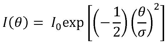 where, θ is the angle (degree) from the specular direction, I(θ) is radiance in the θ direction, I0 is radiance in the specular direction, and σ (sigma) is the standard deviation (or scattering factor) of the Gaussian distribution, in degree. As σ increases, the scattering angle increases. [0106] Zemax ray tracing software (Zemax, LLC of Kirkland, Washington, USA) was utilized to model distinctness‐of‐image, pixel power deviation, and transmission haze as a function of change of elevation (height) of the primary surface features and the σ provided by the secondary surface features. The modeling assumed that the substrate had a thickness of 0.3 mm, that the refractive index of the substrate was 1.49, and the substrate had no light absorption. [0107] FIG. 7A reproduces a graph of the calculations of the model pertaining to distinctness‐of‐ image. As the graph reveals, increasing change in elevation (i.e., height or depth) of the primary surface features decreases distinctness‐of‐image. When no secondary surface features are present (sigma = 0) on the primary surface features, then the primary surface features do not begin to decrease distinctness‐of‐image until the change in elevation (height or depth) is greater than 0.08 µm. However, when secondary surface features are present on the primary surface features, increasing height of the primary surface features instantly causes a decrease in distinctness‐of‐image. [0108] FIG. 7B reproduces a graph illustrating the difference the presence of secondary surface features on the primary surface features makes for decreasing distinctness‐of‐image compared to if the secondary surface features were absent. When sigma=0.20 degree, the presence of the secondary surface features further decreases the distinctness‐of‐image, compared to if no secondary surface features were present, for all heights of the primary surface features from ‐ 0.24 µm to + 0.24 µm. The presence of the secondary surfaces features (providing σ = 0.20 degrees) decreases the distinctness‐of‐image by a maximum of ~29% when the height of the primary surface features is ~ 0.10 µm, compared to if no secondary surface features were present. When σ = 0.41 degree, the presence of the secondary surface features further decreases the distinctness‐of‐image, compared to if no secondary surface features were present, for all heights of the primary surface features from ‐0.27 µm to + 0.27. The presence of the secondary surfaces features (providing σ = 0.41 degrees) decreases the distinctness‐of‐image by
a maximum of ~25% when the height of the primary surface features is ~ 0.18 µm, compared to if no secondary surface features were present. [0109] In short, for any given height/depth of the primary surface features, there is an optimal σ value to be incorporated as the secondary surface features in order to maximize the contribution that the secondary surface features has on decreasing the distinctness‐of‐image. The graph reproduced at FIG. 7C reveals the optimum value for σ , to minimize distinctness‐of‐image, as a function of change in elevation (height) of the primary surface features. The smallest distinctness‐of‐image values of 92%, 66%, 49% respectively for primary surface feature heights of 0.00 (flat), ‐0.10 µm, and ‐0.14 µm are achieved with σ being 0.14, 0.20, and 0.28 degree, respectively. [0110] Next, the modeling software calculated pixel power deviation as a function of the height of the primary surface features and σ value. FIGS. 7D and 7E each reproduce a graph of the calculations. The graphs reveals that, as the height of the primary surface features increases, the pixel power deviation increases. However, as the value for σ provided by the secondary surface features increases, for any given height of the primary surface features, the pixel power deviation decreases. The secondary surface features cause scattering that evens the angular and spatial distributions of the light transmitting through the primary surface features and thus reduces the pixel power deviation. The effect that the secondary surface features have on reducing pixel power deviation becomes greater as the height of the primary surface features increases. In short, the presence of the secondary surface features on the primary surface features introduces surface scattering that can reduce distinctness‐of‐image (for a given range of heights of the primary surface features) and generally reduces pixel power deviation. [0111] Finally, the modeling software calculated transmission haze as a function of the height of the primary surface features and σ value. FIGS. 7F and 7G each reproduce a graph of the calculations. The graph of FIG. 7F reveals that increasing σ value increases generally increases pixel power deviation, and increasing the height of the primary surface features magnifies the affect that increasing σ value on increasing pixel power deviation (but only slightly). The graph of FIG. 7G reveals however that σ has to be above a certain value before σ causes an increase in pixel power deviation. In the instance of FIG. 7G, where the primary surface features were
assumed to have a height of ‐0.1 µm and a width of 100 µm, the σ only begins to increase pixel power deviation when the value for σ is about 0.35 or higher. The value for σ can be greater than 0.35, in order to further reduce pixel power deviation and distinctness‐of‐image, if those benefits outweigh the increase in transmission haze. For example, even at a σ value of 0.7 degree, which maximizes the reduction in pixel power deviation and distinctness‐of‐image, the transmission haze is only 20%, which may be acceptable for a given application. [0112] Thus, as long as the σ value is configured to be right below 0.35, the affect that the secondary features have on decreasing distinctness‐of‐image and pixel power deviation does not simultaneously cause an increase in transmission haze. For example, when the height of the primary surface features are ‐0.1 µm and the σ value is 0.41 degree, the calculated distinctness‐ of‐image is ~74%, the pixel power deviation is ~2.5%, and the transmission haze is ~1%. When the height of the primary surface features are ‐0.1 µm and the σ value is 0.2 degree, the calculated distinctness‐of‐image is ~64%, the pixel power deviation is ~3.5%, and the transmission haze is ~0%. When the height of the primary surface features are ‐0.08 µm and the σ value is 0.41 degree, the calculated distinctness‐of‐image is ~85%, the pixel power deviation is ~2%, and the transmission haze is ~0%. When the height of the primary surface features are ‐ 0.08 µm and the σ value is 0.20 degree, the calculated distinctness‐of‐image is ~73%, the pixel power deviation is ~2.5%, and the transmission haze is ~0%. [0113] In sum, the modeling demonstrates that the incorporation of the secondary surface features on the primary surface features to impart the surface roughness that causes a certain scattering level can result in a low distinctness‐of‐image, low pixel power deviation, and low transmission haze all simultaneously – something not achievable with previous methods of forming the textured region. [0114] Examples 2A‐2D – For Examples 2A‐2D, four (4) samples of glass were prepared. Each sample was etched with an etchant of differing compositions to model the effect that the etchant would have on the generation of secondary surface features to impart a surface roughness within a range of 5 nm to 100 nm. All compositions of the etchant included acetic acid and ammonium fluoride (NH4F) in varying weight percentages. Table 1, immediately, below summarizes the compositions of the four etchants tested.
where, θ is the angle (degree) from the specular direction, I(θ) is radiance in the θ direction, I0 is radiance in the specular direction, and σ (sigma) is the standard deviation (or scattering factor) of the Gaussian distribution, in degree. As σ increases, the scattering angle increases. [0106] Zemax ray tracing software (Zemax, LLC of Kirkland, Washington, USA) was utilized to model distinctness‐of‐image, pixel power deviation, and transmission haze as a function of change of elevation (height) of the primary surface features and the σ provided by the secondary surface features. The modeling assumed that the substrate had a thickness of 0.3 mm, that the refractive index of the substrate was 1.49, and the substrate had no light absorption. [0107] FIG. 7A reproduces a graph of the calculations of the model pertaining to distinctness‐of‐ image. As the graph reveals, increasing change in elevation (i.e., height or depth) of the primary surface features decreases distinctness‐of‐image. When no secondary surface features are present (sigma = 0) on the primary surface features, then the primary surface features do not begin to decrease distinctness‐of‐image until the change in elevation (height or depth) is greater than 0.08 µm. However, when secondary surface features are present on the primary surface features, increasing height of the primary surface features instantly causes a decrease in distinctness‐of‐image. [0108] FIG. 7B reproduces a graph illustrating the difference the presence of secondary surface features on the primary surface features makes for decreasing distinctness‐of‐image compared to if the secondary surface features were absent. When sigma=0.20 degree, the presence of the secondary surface features further decreases the distinctness‐of‐image, compared to if no secondary surface features were present, for all heights of the primary surface features from ‐ 0.24 µm to + 0.24 µm. The presence of the secondary surfaces features (providing σ = 0.20 degrees) decreases the distinctness‐of‐image by a maximum of ~29% when the height of the primary surface features is ~ 0.10 µm, compared to if no secondary surface features were present. When σ = 0.41 degree, the presence of the secondary surface features further decreases the distinctness‐of‐image, compared to if no secondary surface features were present, for all heights of the primary surface features from ‐0.27 µm to + 0.27. The presence of the secondary surfaces features (providing σ = 0.41 degrees) decreases the distinctness‐of‐image by
a maximum of ~25% when the height of the primary surface features is ~ 0.18 µm, compared to if no secondary surface features were present. [0109] In short, for any given height/depth of the primary surface features, there is an optimal σ value to be incorporated as the secondary surface features in order to maximize the contribution that the secondary surface features has on decreasing the distinctness‐of‐image. The graph reproduced at FIG. 7C reveals the optimum value for σ , to minimize distinctness‐of‐image, as a function of change in elevation (height) of the primary surface features. The smallest distinctness‐of‐image values of 92%, 66%, 49% respectively for primary surface feature heights of 0.00 (flat), ‐0.10 µm, and ‐0.14 µm are achieved with σ being 0.14, 0.20, and 0.28 degree, respectively. [0110] Next, the modeling software calculated pixel power deviation as a function of the height of the primary surface features and σ value. FIGS. 7D and 7E each reproduce a graph of the calculations. The graphs reveals that, as the height of the primary surface features increases, the pixel power deviation increases. However, as the value for σ provided by the secondary surface features increases, for any given height of the primary surface features, the pixel power deviation decreases. The secondary surface features cause scattering that evens the angular and spatial distributions of the light transmitting through the primary surface features and thus reduces the pixel power deviation. The effect that the secondary surface features have on reducing pixel power deviation becomes greater as the height of the primary surface features increases. In short, the presence of the secondary surface features on the primary surface features introduces surface scattering that can reduce distinctness‐of‐image (for a given range of heights of the primary surface features) and generally reduces pixel power deviation. [0111] Finally, the modeling software calculated transmission haze as a function of the height of the primary surface features and σ value. FIGS. 7F and 7G each reproduce a graph of the calculations. The graph of FIG. 7F reveals that increasing σ value increases generally increases pixel power deviation, and increasing the height of the primary surface features magnifies the affect that increasing σ value on increasing pixel power deviation (but only slightly). The graph of FIG. 7G reveals however that σ has to be above a certain value before σ causes an increase in pixel power deviation. In the instance of FIG. 7G, where the primary surface features were
assumed to have a height of ‐0.1 µm and a width of 100 µm, the σ only begins to increase pixel power deviation when the value for σ is about 0.35 or higher. The value for σ can be greater than 0.35, in order to further reduce pixel power deviation and distinctness‐of‐image, if those benefits outweigh the increase in transmission haze. For example, even at a σ value of 0.7 degree, which maximizes the reduction in pixel power deviation and distinctness‐of‐image, the transmission haze is only 20%, which may be acceptable for a given application. [0112] Thus, as long as the σ value is configured to be right below 0.35, the affect that the secondary features have on decreasing distinctness‐of‐image and pixel power deviation does not simultaneously cause an increase in transmission haze. For example, when the height of the primary surface features are ‐0.1 µm and the σ value is 0.41 degree, the calculated distinctness‐ of‐image is ~74%, the pixel power deviation is ~2.5%, and the transmission haze is ~1%. When the height of the primary surface features are ‐0.1 µm and the σ value is 0.2 degree, the calculated distinctness‐of‐image is ~64%, the pixel power deviation is ~3.5%, and the transmission haze is ~0%. When the height of the primary surface features are ‐0.08 µm and the σ value is 0.41 degree, the calculated distinctness‐of‐image is ~85%, the pixel power deviation is ~2%, and the transmission haze is ~0%. When the height of the primary surface features are ‐ 0.08 µm and the σ value is 0.20 degree, the calculated distinctness‐of‐image is ~73%, the pixel power deviation is ~2.5%, and the transmission haze is ~0%. [0113] In sum, the modeling demonstrates that the incorporation of the secondary surface features on the primary surface features to impart the surface roughness that causes a certain scattering level can result in a low distinctness‐of‐image, low pixel power deviation, and low transmission haze all simultaneously – something not achievable with previous methods of forming the textured region. [0114] Examples 2A‐2D – For Examples 2A‐2D, four (4) samples of glass were prepared. Each sample was etched with an etchant of differing compositions to model the effect that the etchant would have on the generation of secondary surface features to impart a surface roughness within a range of 5 nm to 100 nm. All compositions of the etchant included acetic acid and ammonium fluoride (NH4F) in varying weight percentages. Table 1, immediately, below summarizes the compositions of the four etchants tested.

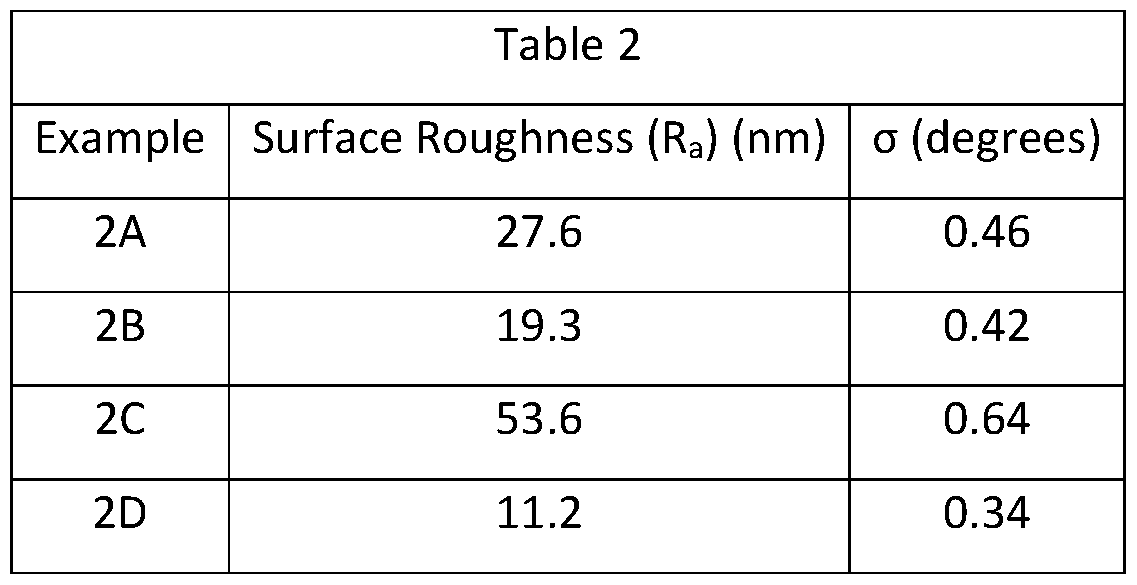


Claims
CLAIM(S) What is claimed is: 1. A substrate for a display article, the substrate comprising: a primary surface; and a textured region on at least a portion of the primary surface; the textured region comprising: primary surface features, each comprising a perimeter parallel to a base‐plane extending through the substrate disposed below the textured region, wherein the perimeter of each of the primary surface features comprises a longest dimension of at least 5 µm; and one or more sections each comprising secondary surface features having a surface roughness (Ra) within a range of 5 nm to 100 nm.
2. The substrate of claim 1, wherein the primary surface features form a pattern.
3. The substrate of any one of claims 1‐2, wherein the longest dimension of each of the primary surface features is about the same.
4. The substrate of any one of claims 1‐3, wherein an arrangement of the surface features reflect a random distribution.
5. The substrate of any one of claims 1‐4, wherein the perimeter of each primary surface features is elliptical.
6. The substrate of any one of claims 1‐4, wherein the perimeter of each primary surface features is circular.
7. The substrate of any one of claims 1‐4, wherein
each primary surface feature provides a surface, and the surface is either concave or convex.
8. The substrate of any one of claims 1‐7, wherein the textured region further comprises: a surrounding portion into which the primary surface features are set or out of which the primary surface features project.
9. The substrate of any one of claims 1‐8, wherein the primary surface features that are adjacent to one another have perimeters that are separated by a distance within a range of 1 µm to 100 µm; and the primary surface features that are adjacent to one another are separated by a center‐ to‐center distance within a range of 5 µm to 150 µm.
10. The substrate of any one of claims 1‐9, wherein each of the primary surface features comprises a change in elevation perpendicular to the base‐plane that is within a range of 0.05 µm to 0.50 µm.
11. The substrate of any one of claims 1‐6 and 8‐10, wherein each primary surface features provides a surface, and the secondary surface features are disposed on the surfaces of the primary surface features.
12. The substrate of any one of claims 1‐6, 9, and 10, wherein the textured region further comprises: a surrounding portion into which the primary surface features are set into or out of which the primary surface features project; wherein, each primary surface feature provides a surface, wherein, the secondary surface features are disposed on both the surrounding portion and on the surfaces of the primary surface features, and
wherein, the surface roughness at the surfaces of the primary surface features is less than the surface roughness at the surrounding portion.
13. The substrate of any one of claims 1‐6, 9, and 10 further comprising: a surrounding portion into which the primary surface features are set into or out of which the primary surface features project; wherein, the secondary surface features are disposed on the surfaces of the primary surface features but not on the surrounding portion.
14. The substrate of any one of claims 1‐13, wherein the substrate comprises a glass or glass‐ceramic.
15. The substrate of any one of claims 1‐14, wherein the textured region exhibits a transmission haze within a range of 1.5% to 3.5%; the textured region exhibits a pixel power deviation within a range of 1.5% to 3.5%; the textured region exhibits a distinctness‐of‐image within a range of 2.% to 5.0%; and the textured region exhibits a specular reflectance within a range of 5 GU to 20 GU.
16. A method of forming a textured region of a substrate, the method comprising: forming primary surface features into a primary surface of a substrate according to a predetermined positioning of each primary surface feature thus forming a textured region, each primary surface feature comprising a largest dimension parallel to a base‐plane through the substrate disposed below the primary surface of at least 5 µm; and forming secondary surface features into one or more sections of the textured region, thereby increasing the surface roughness (Ra) of the one or more sections to within a range of 5 nm to 100 nm.
17. The method of claim 16 further comprising:
determining the positioning of each primary surface feature utilizing a spacing distribution algorithm.
18. The method of any one of claims 16‐17, wherein forming the primary surface features into the primary surface comprises contacting the primary surface with an etchant while an etching mask is disposed on the primary surface to permit only selective etching of the substrate to form the primary surface features.
19. The method of claim 18, wherein the etchant comprises hydrofluoric acid and nitric acid; and the etchant contacts the substrate for a time period within a range of 10 seconds to 60 seconds.
20. The method of any one of claims 16‐19 further comprising: forming the etching mask by exposing a photorsesist material disposed on the primary surface of the substrate to a curing agent while a lithography mask is disposed on the photoresist material, the lithography mask comprising material and voids through the material to selectively expose portions of the photoresist material to the curing agent, wherein the voids of the lithography mask are positioned according to the predetermined positioning of the primary surface features.
21. The method of any one of claims 16‐20, wherein forming the secondary surface features into one or more sections of the textured region comprises contacting the textured region of the substrate with a second etchant, different than the etchant used to form the primary surface features.
22. The method of any one of claims 16‐21, wherein the second etchant comprises acetic acid and ammonium fluoride.
23. The method of any one of claims 16‐22, wherein forming the primary surface features into the primary surface comprises contacting the primary surface with an etchant while an etching mask is disposed on the primary surface to permit only selective etching of the substrate to form the primary surface features, and forming the secondary surface features into one or more sections of the textured region comprises contacting the one or more sections of the textured region of the substrate with a second etchant, different than the etchant used to form the primary surface features, while the etching mask used to form the primary surface features remains on the substrate.
Applications Claiming Priority (2)
| Application Number | Priority Date | Filing Date | Title |
|---|---|---|---|
| US202063049843P | 2020-07-09 | 2020-07-09 | |
| US63/049,843 | 2020-07-09 |
Publications (2)
| Publication Number | Publication Date |
|---|---|
| WO2022011073A1 true WO2022011073A1 (en) | 2022-01-13 |
| WO2022011073A9 WO2022011073A9 (en) | 2022-02-10 |
Family
ID=77155899
Family Applications (6)
| Application Number | Title | Priority Date | Filing Date |
|---|---|---|---|
| PCT/US2021/040770 Ceased WO2022011068A1 (en) | 2020-07-09 | 2021-07-08 | Display articles with diffractive, antiglare surfaces and methods of making the same |
| PCT/US2021/040773 Ceased WO2022011071A1 (en) | 2020-07-09 | 2021-07-08 | Textured region of a substrate to reduce specular reflectance incorporating surface features with an elliptical perimeter or segments thereof, and method of making the same |
| PCT/US2021/040775 Ceased WO2022011073A1 (en) | 2020-07-09 | 2021-07-08 | Anti-glare substrate for a display article including a textured region with primary surface features and secondary surface features imparting a surface roughness that increases surface scattering |
| PCT/US2021/040774 Ceased WO2022011072A1 (en) | 2020-07-09 | 2021-07-08 | Display articles with antiglare surfaces and thin, durable antireflection coatings |
| PCT/US2021/040772 Ceased WO2022011070A1 (en) | 2020-07-09 | 2021-07-08 | Textured region to reduce specular reflectance including a low refractive index substrate with higher elevated surfaces and lower elevated surfaces and a high refractive index material disposed on the lower elevated surfaces |
| PCT/US2021/040771 Ceased WO2022011069A1 (en) | 2020-07-09 | 2021-07-08 | Display articles with diffractive, antiglare surfaces and thin, durable antireflection coatings |
Family Applications Before (2)
| Application Number | Title | Priority Date | Filing Date |
|---|---|---|---|
| PCT/US2021/040770 Ceased WO2022011068A1 (en) | 2020-07-09 | 2021-07-08 | Display articles with diffractive, antiglare surfaces and methods of making the same |
| PCT/US2021/040773 Ceased WO2022011071A1 (en) | 2020-07-09 | 2021-07-08 | Textured region of a substrate to reduce specular reflectance incorporating surface features with an elliptical perimeter or segments thereof, and method of making the same |
Family Applications After (3)
| Application Number | Title | Priority Date | Filing Date |
|---|---|---|---|
| PCT/US2021/040774 Ceased WO2022011072A1 (en) | 2020-07-09 | 2021-07-08 | Display articles with antiglare surfaces and thin, durable antireflection coatings |
| PCT/US2021/040772 Ceased WO2022011070A1 (en) | 2020-07-09 | 2021-07-08 | Textured region to reduce specular reflectance including a low refractive index substrate with higher elevated surfaces and lower elevated surfaces and a high refractive index material disposed on the lower elevated surfaces |
| PCT/US2021/040771 Ceased WO2022011069A1 (en) | 2020-07-09 | 2021-07-08 | Display articles with diffractive, antiglare surfaces and thin, durable antireflection coatings |
Country Status (7)
| Country | Link |
|---|---|
| US (10) | US12147009B2 (en) |
| EP (5) | EP4178925A1 (en) |
| JP (1) | JP7839596B2 (en) |
| KR (4) | KR20230038505A (en) |
| CN (6) | CN116133998B (en) |
| TW (3) | TWI899279B (en) |
| WO (6) | WO2022011068A1 (en) |
Families Citing this family (15)
| Publication number | Priority date | Publication date | Assignee | Title |
|---|---|---|---|---|
| US9110230B2 (en) | 2013-05-07 | 2015-08-18 | Corning Incorporated | Scratch-resistant articles with retained optical properties |
| TWI821234B (en) | 2018-01-09 | 2023-11-11 | 美商康寧公司 | Coated articles with light-altering features and methods for the production thereof |
| CN111204989A (en) * | 2018-11-22 | 2020-05-29 | 康宁股份有限公司 | Low warpage reinforced article and asymmetric ion exchange method for making same |
| US12147009B2 (en) | 2020-07-09 | 2024-11-19 | Corning Incorporated | Textured region to reduce specular reflectance including a low refractive index substrate with higher elevated surfaces and lower elevated surfaces and a high refractive index material disposed on the lower elevated surfaces |
| WO2022115553A1 (en) * | 2020-11-30 | 2022-06-02 | Corning Incorporated | Textured glass-based articles with multiple haze levels and processes of producing the same |
| CN117836248A (en) * | 2021-07-06 | 2024-04-05 | 康宁公司 | Anti-glare substrate for display articles having a textured region including one or more surfaces at two, three or four elevations and surface features providing at least a portion of one or more surfaces and methods of making the same |
| EP4499581A1 (en) * | 2022-03-30 | 2025-02-05 | Corning Incorporated | Multi-level structured surface for anti-glare application and associated methods |
| US20240028070A1 (en) * | 2022-07-22 | 2024-01-25 | Apple Inc. | Coatings for Textured Glass |
| WO2024091468A1 (en) * | 2022-10-28 | 2024-05-02 | Corning Incorporated | Articles with anti-glare surfaces exhibiting low sparkle with minimal color artifacts |
| CN120153291A (en) * | 2022-10-28 | 2025-06-13 | 康宁股份有限公司 | Articles having an anti-glare surface with an inclined transition surface and related methods |
| WO2024118373A1 (en) * | 2022-11-30 | 2024-06-06 | Corning Incorporated | Textured articles and methods for making the same |
| US20240191099A1 (en) | 2022-12-08 | 2024-06-13 | Corning Incorporated | Coated articles with an anti-fingerprint coating or surface-modifying layer and methods of making the same |
| WO2024196577A1 (en) * | 2023-03-17 | 2024-09-26 | Corning Incorporated | Screen protectors tailored for electronic device displays |
| KR20260048290A (en) * | 2023-08-03 | 2026-04-09 | 코닝 인코포레이티드 | Glare-resistant surface with wear resistance |
| WO2025136775A1 (en) * | 2023-12-21 | 2025-06-26 | Corning Incorporated | Antiglare articles |
Citations (7)
| Publication number | Priority date | Publication date | Assignee | Title |
|---|---|---|---|---|
| US20150174625A1 (en) * | 2011-11-30 | 2015-06-25 | Corning Incorporated | Articles with monolithic, structured surfaces and methods for making and using same |
| WO2015095288A2 (en) * | 2013-12-19 | 2015-06-25 | Corning Incorporated | Textured surfaces for display applications |
| US9411180B2 (en) | 2011-02-28 | 2016-08-09 | Corning Incorporated | Apparatus and method for determining sparkle |
| US20160236974A1 (en) * | 2014-07-09 | 2016-08-18 | Agc Glass Europe | Low sparkle glass sheet |
| WO2016205317A1 (en) * | 2015-06-19 | 2016-12-22 | Corning Incorporated | Method of decorating a substrate surface and articles thereby |
| US20170285227A1 (en) * | 2014-10-31 | 2017-10-05 | Corning Incorporated | Anti-glare substrates with a uniform textured surface and low sparkle and methods of making the same |
| WO2020123367A1 (en) * | 2018-12-10 | 2020-06-18 | Corning Incorporated | Dynamically bendable automotive interior display systems |
Family Cites Families (879)
| Publication number | Priority date | Publication date | Assignee | Title |
|---|---|---|---|---|
| USD31977S (en) | 1899-11-16 | 1899-12-12 | John Schmitt | Design for a housing for gear-wheels |
| US3067021A (en) | 1955-12-08 | 1962-12-04 | Wheelabrator Corp | Subbing surfaces |
| US3150032A (en) | 1956-06-25 | 1964-09-22 | Rubenstein David | Abuse resistant articles of manufacture and method of making |
| US3413058A (en) | 1964-07-09 | 1968-11-26 | Minnesota Mining & Mfg | Reflex-reflecting articles |
| US3934961A (en) | 1970-10-29 | 1976-01-27 | Canon Kabushiki Kaisha | Three layer anti-reflection film |
| JPS5314227B2 (en) | 1973-06-18 | 1978-05-16 | ||
| GB1517585A (en) | 1974-11-13 | 1978-07-12 | Mobay Chemical Corp | Process for the production of a polyamino-polyphenyl-(poly)-methylene polyamine |
| US3989350A (en) | 1975-09-12 | 1976-11-02 | Bell Telephone Laboratories, Incorporated | Multimode optical fiber |
| US4033667A (en) | 1975-09-12 | 1977-07-05 | Bell Telephone Laboratories, Incorporated | Multimode optical fiber |
| CA1077787A (en) | 1975-11-21 | 1980-05-20 | National Aeronautics And Space Administration | Abrasion resistant coatings for plastic surfaces |
| US4423925A (en) | 1979-07-13 | 1984-01-03 | Times Fiber Communications, Inc. | Graded optical waveguides |
| US4298366A (en) | 1979-07-13 | 1981-11-03 | Times Fiber Communications, Inc. | Graded start rods for the production of optical waveguides |
| US4310595A (en) | 1980-10-31 | 1982-01-12 | Corning Glass Works | Peraluminious nepheline/kalsilite glass-ceramics |
| US4504519A (en) | 1981-10-21 | 1985-03-12 | Rca Corporation | Diamond-like film and process for producing same |
| JPS58127463A (en) | 1982-01-25 | 1983-07-29 | Nippon Telegr & Teleph Corp <Ntt> | Close contact type image sensor |
| DE3230388A1 (en) | 1982-08-14 | 1984-02-16 | Karl Schmidt Gmbh, 7107 Neckarsulm | METHOD FOR CONNECTING AN INLET POWDERED INTO A COMPONENT MOLDED IN A LIGHT METAL MATERIAL FOR INTERNAL COMBUSTION ENGINE |
| DE3248103C1 (en) | 1982-12-24 | 1987-11-12 | W.C. Heraeus Gmbh, 6450 Hanau | Crucible for pulling single crystals |
| JPS59138440A (en) | 1983-01-27 | 1984-08-08 | 豊田合成株式会社 | Resin shape with ceramics coating layer |
| NL8301824A (en) | 1983-05-24 | 1984-12-17 | Philips Nv | OPTICAL ELEMENT COMPRISING A TRANSPARENT SUBSTRATE AND ANTI-REFLECTIVE CLOTHING FOR THE WAVE LENGTH AREA IN THE NEAR INFRARED. |
| JPS60119114A (en) | 1983-11-30 | 1985-06-26 | Murata Mfg Co Ltd | Surface wave device |
| DE3422289A1 (en) | 1984-06-15 | 1985-12-19 | Hoechst Ag, 6230 Frankfurt | METHOD FOR IMPROVING THE USE PROPERTIES OF TUFTED FLOORING |
| EP0166363B1 (en) | 1984-06-26 | 1991-08-07 | Asahi Glass Company Ltd. | Low reflectance transparent material having antisoiling properties |
| US4705356A (en) | 1984-07-13 | 1987-11-10 | Optical Coating Laboratory, Inc. | Thin film optical variable article having substantial color shift with angle and method |
| US5300951A (en) | 1985-11-28 | 1994-04-05 | Kabushiki Kaisha Toshiba | Member coated with ceramic material and method of manufacturing the same |
| US4995684A (en) | 1986-06-18 | 1991-02-26 | Raytheon Company | Impact resistant and tempered optical elements |
| US5071206A (en) | 1986-06-30 | 1991-12-10 | Southwall Technologies Inc. | Color-corrected heat-reflecting composite films and glazing products containing the same |
| US5332888A (en) | 1986-08-20 | 1994-07-26 | Libbey-Owens-Ford Co. | Sputtered multi-layer color compatible solar control coating |
| LU86722A1 (en) | 1986-12-23 | 1988-07-14 | Glaverbel | SHEET OF GLASS MATERIAL CARRYING A SERIOUS DRAWING AND METHOD FOR ENGRAVING A DRAWING ON A SUBSTRATE OF GLASS MATERIAL |
| JPS63238260A (en) | 1987-03-25 | 1988-10-04 | Unitika Ltd | Formation of heat ray reflecting film |
| JPS63265846A (en) | 1987-04-22 | 1988-11-02 | Nippon Sheet Glass Co Ltd | Bent heat ray reflection glass and production thereof |
| JPH0735267B2 (en) | 1987-04-22 | 1995-04-19 | 日本板硝子株式会社 | Method for manufacturing bent heat ray reflective glass |
| US4945282A (en) | 1987-12-10 | 1990-07-31 | Hitachi, Ltd. | Image display panel having antistatic film with transparent and electroconductive properties and process for processing same |
| US4851095A (en) | 1988-02-08 | 1989-07-25 | Optical Coating Laboratory, Inc. | Magnetron sputtering apparatus and process |
| US4946923A (en) | 1988-02-18 | 1990-08-07 | Mitsui Toatsu Chemicals, Inc. | S-alkyl thiocarbamate base resin, plastic lens comprising the resin, and process for making the lens |
| US5605609A (en) | 1988-03-03 | 1997-02-25 | Asahi Glass Company Ltd. | Method for forming low refractive index film comprising silicon dioxide |
| US4826734A (en) | 1988-03-03 | 1989-05-02 | Union Carbide Corporation | Tungsten carbide-cobalt coatings for various articles |
| US4896928A (en) | 1988-08-29 | 1990-01-30 | Coherent, Inc. | Chromatically invariant multilayer dielectric thin film coating |
| JPH02156448A (en) | 1988-12-08 | 1990-06-15 | Daicel Chem Ind Ltd | Magneto-optical recording medium |
| JPH0277434A (en) | 1989-05-29 | 1990-03-16 | Toray Ind Inc | Molding containing transparent coating layer |
| CA2017471C (en) | 1989-07-19 | 2000-10-24 | Matthew Eric Krisl | Optical interference coatings and lamps using same |
| USD326303S (en) | 1989-07-25 | 1992-05-19 | Ray Cook Company | Golf putter head |
| KR0151706B1 (en) | 1989-09-29 | 1998-12-15 | 나가이 야따로 | Refractive distribution type optical transmitter and its manufacturing method |
| US5178911A (en) | 1989-11-30 | 1993-01-12 | The President And Fellows Of Harvard College | Process for chemical vapor deposition of main group metal nitrides |
| US5637353A (en) | 1990-09-27 | 1997-06-10 | Monsanto Company | Abrasion wear resistant coated substrate product |
| US5268217A (en) | 1990-09-27 | 1993-12-07 | Diamonex, Incorporated | Abrasion wear resistant coated substrate product |
| US5527596A (en) | 1990-09-27 | 1996-06-18 | Diamonex, Incorporated | Abrasion wear resistant coated substrate product |
| JPH04250834A (en) | 1991-01-07 | 1992-09-07 | Fuji Photo Film Co Ltd | Precision filter membrane |
| US5535056A (en) | 1991-05-15 | 1996-07-09 | Donnelly Corporation | Method for making elemental semiconductor mirror for vehicles |
| DE4128547A1 (en) | 1991-08-28 | 1993-03-04 | Leybold Ag | METHOD AND DEVICE FOR THE PRODUCTION OF A RE-MIRRORING LAYER ON LENSES |
| TW266301B (en) | 1991-09-19 | 1995-12-21 | Philips Nv | |
| DE4131517A1 (en) * | 1991-09-21 | 1993-03-25 | Hoechst Ag | METHOD FOR PRODUCING REFLECTED SURFACES |
| JP2668472B2 (en) | 1991-10-17 | 1997-10-27 | 信越化学工業株式会社 | Fluorine-containing organosilicon compound |
| DE69219300T2 (en) | 1991-12-26 | 1997-08-14 | Asahi Glass Co Ltd | A transparent film coated substrate |
| US5234769A (en) | 1992-04-16 | 1993-08-10 | Deposition Sciences, Inc. | Wear resistant transparent dielectric coatings |
| US5342681A (en) | 1992-08-28 | 1994-08-30 | Texas Instruments Incorporated | Absorbing, low reflecting coating for visible and infrared light |
| EP0592986B1 (en) | 1992-10-12 | 1998-07-08 | Sumitomo Electric Industries, Limited | Ultra-thin film laminate |
| FR2697242B1 (en) | 1992-10-22 | 1994-12-16 | Saint Gobain Vitrage Int | Chemical toughened glazing. |
| US5557313A (en) | 1992-11-12 | 1996-09-17 | Tdk Corporation | Wear-resistant protective film for thermal head and method of producing the same |
| JP2875945B2 (en) | 1993-01-28 | 1999-03-31 | アプライド マテリアルズ インコーポレイテッド | Method of depositing silicon nitride thin film on large area glass substrate at high deposition rate by CVD |
| JP2974879B2 (en) | 1993-04-07 | 1999-11-10 | アルプス電気株式会社 | Synthesis method by plasma CVD |
| US5549953A (en) | 1993-04-29 | 1996-08-27 | National Research Council Of Canada | Optical recording media having optically-variable security properties |
| BE1007662A3 (en) | 1993-10-18 | 1995-09-05 | Philips Electronics Nv | A picture display device having a display screen having an antistatic and light absorbing coating layer. |
| US5737472A (en) | 1993-12-17 | 1998-04-07 | Audio-Images S.A.R.L. | Optical fiber with multiple point lateral illumination |
| GB9400259D0 (en) * | 1994-01-07 | 1994-03-02 | Pilkington Plc | Substrate for a magnetic disc and manufacture thereof |
| US5909314A (en) | 1994-02-15 | 1999-06-01 | Dai Nippon Printing Co., Ltd. | Optical functional materials and process for producing the same |
| US5618619A (en) | 1994-03-03 | 1997-04-08 | Monsanto Company | Highly abrasion-resistant, flexible coatings for soft substrates |
| US5846649A (en) | 1994-03-03 | 1998-12-08 | Monsanto Company | Highly durable and abrasion-resistant dielectric coatings for lenses |
| JP3374299B2 (en) | 1994-04-20 | 2003-02-04 | 大日本印刷株式会社 | Anti-glare film |
| JPH07331115A (en) | 1994-06-10 | 1995-12-19 | Toyo Ink Mfg Co Ltd | Composition for antireflection film |
| JPH0864848A (en) | 1994-08-23 | 1996-03-08 | Canon Inc | Photoelectric conversion device, antireflection film, and electrode substrate |
| DE4430363A1 (en) | 1994-08-26 | 1996-02-29 | Leybold Ag | Optical lens made of a clear plastic |
| KR960014166A (en) | 1994-10-14 | 1996-05-22 | 양승택 | Manufacturing Method of Polymeric GRIN Lens Using Sulfide |
| DE4445427C2 (en) | 1994-12-20 | 1997-04-30 | Schott Glaswerke | Plasma CVD method for producing a gradient layer |
| US5811191A (en) | 1994-12-27 | 1998-09-22 | Ppg Industries, Inc. | Multilayer antireflective coating with a graded base layer |
| EP0728618A3 (en) | 1995-02-22 | 1996-11-06 | Gentex Corp | Anti-glare rear view mirror for motor vehicles |
| FR2730990B1 (en) | 1995-02-23 | 1997-04-04 | Saint Gobain Vitrage | TRANSPARENT SUBSTRATE WITH ANTI-REFLECTIVE COATING |
| EP0730044B1 (en) | 1995-03-01 | 2001-06-20 | Sumitomo Electric Industries, Limited | Boron-aluminum nitride coating and method of producing same |
| US5719705A (en) | 1995-06-07 | 1998-02-17 | Sola International, Inc. | Anti-static anti-reflection coating |
| FR2736632B1 (en) | 1995-07-12 | 1997-10-24 | Saint Gobain Vitrage | GLAZING PROVIDED WITH A CONDUCTIVE AND / OR LOW-EMISSIVE LAYER |
| JPH0968602A (en) | 1995-08-30 | 1997-03-11 | Nikon Corp | Optical article having antireflection layer |
| DE19537263C2 (en) | 1995-10-06 | 1998-02-26 | Fraunhofer Ges Forschung | Transparent heat protection film and process for its production |
| US5846650A (en) | 1996-05-10 | 1998-12-08 | Minnesota Mining And Manufacturing Company | Anti-reflective, abrasion resistant, anti-fogging coated articles and methods |
| JP3225348B2 (en) | 1996-06-15 | 2001-11-05 | 有限会社野上商事 | Weeding sickle |
| WO1998010916A1 (en) | 1996-09-12 | 1998-03-19 | University Of Florida | A novel production method for objects with radially-varying properties |
| US6172812B1 (en) | 1997-01-27 | 2001-01-09 | Peter D. Haaland | Anti-reflection coatings and coated articles |
| FR2759362B1 (en) | 1997-02-10 | 1999-03-12 | Saint Gobain Vitrage | TRANSPARENT SUBSTRATE EQUIPPED WITH AT LEAST ONE THIN LAYER BASED ON SILICON NITRIDE OR OXYNITRIDE AND ITS PROCESS FOR OBTAINING IT |
| GB9703616D0 (en) | 1997-02-21 | 1997-04-09 | Univ Paisley | Thin films |
| JPH10253840A (en) | 1997-03-07 | 1998-09-25 | Sumitomo Wiring Syst Ltd | Manufacture of refractive index distribution type plastic optical fiber and manufacturing device therefor |
| US6482524B1 (en) | 1997-03-11 | 2002-11-19 | Nippon Sheet Glass Co., Ltd. | Substrate having a treatment surface |
| CN1130575C (en) | 1997-05-16 | 2003-12-10 | 保谷株式会社 | Plastic optical device with antireflection film and mechanism for making thickness of antireflection film uniform |
| US6495251B1 (en) | 1997-06-20 | 2002-12-17 | Ppg Industries Ohio, Inc. | Silicon oxynitride protective coatings |
| CN1262611A (en) | 1997-07-02 | 2000-08-09 | 纽创基纳有限公司 | Methods of treating seborrheic dermatitis, dandruff, psoriasis and acne with dichlorophenylimidazodioxolane-containing compositions and compositions thereof |
| US5935716A (en) | 1997-07-07 | 1999-08-10 | Libbey-Owens-Ford Co. | Anti-reflective films |
| US6129980A (en) | 1997-07-11 | 2000-10-10 | Fuji Photo Film Co., Ltd. | Anti-reflection film and display device having the same |
| EP0893715B1 (en) | 1997-07-21 | 2004-02-04 | European Atomic Energy Community (EURATOM) | Method of producing an optical fibre resonant cavity, in particular for an interferometric sensor, and optical fibre resonant cavity produced thereby |
| CN1112594C (en) | 1997-10-02 | 2003-06-25 | 旭硝子株式会社 | Refractivity distributing optical resin material |
| US5867239A (en) | 1997-10-17 | 1999-02-02 | Minnesota Mining And Manufacturing Company | Wide angle optical retarder |
| JPH11125704A (en) | 1997-10-22 | 1999-05-11 | Dainippon Printing Co Ltd | Lenticular lens sheet and manufacturing method thereof |
| US6607829B1 (en) | 1997-11-13 | 2003-08-19 | Massachusetts Institute Of Technology | Tellurium-containing nanocrystalline materials |
| EP0918044A1 (en) | 1997-11-19 | 1999-05-26 | Glaverbel | Solar control glazing |
| US6074730A (en) | 1997-12-31 | 2000-06-13 | The Boc Group, Inc. | Broad-band antireflection coating having four sputtered layers |
| US6045894A (en) | 1998-01-13 | 2000-04-04 | 3M Innovative Properties Company | Clear to colored security film |
| TW415888B (en) | 1998-02-17 | 2000-12-21 | Nippon Kayaku Kk | Transparent sheet or film |
| US6800378B2 (en) | 1998-02-19 | 2004-10-05 | 3M Innovative Properties Company | Antireflection films for use with displays |
| EP1067407B1 (en) | 1998-02-24 | 2006-04-26 | Asahi Glass Co., Ltd. | Light absorption antireflective body and method of producing the same |
| JP3938636B2 (en) | 1998-02-25 | 2007-06-27 | Hoya株式会社 | High refractive index plastic lens and manufacturing method thereof |
| EP0947601A1 (en) | 1998-03-26 | 1999-10-06 | ESSILOR INTERNATIONAL Compagnie Générale d'Optique | Organic substrate having optical layers deposited by magnetron sputtering and method for preparing it |
| US6391400B1 (en) | 1998-04-08 | 2002-05-21 | Thomas A. Russell | Thermal control films suitable for use in glazing |
| US6583935B1 (en) | 1998-05-28 | 2003-06-24 | Cpfilms Inc. | Low reflection, high transmission, touch-panel membrane |
| FR2781062B1 (en) | 1998-07-09 | 2002-07-12 | Saint Gobain Vitrage | GLAZING WITH ELECTRICALLY CONTROLLED OPTICAL AND / OR ENERGY PROPERTIES |
| US7378146B1 (en) | 1998-08-05 | 2008-05-27 | International Business Machines Corporation | Transparent hard coats for optical elements |
| US6165598A (en) | 1998-08-14 | 2000-12-26 | Libbey-Owens-Ford Co. | Color suppressed anti-reflective glass |
| US6217272B1 (en) | 1998-10-01 | 2001-04-17 | Applied Science And Technology, Inc. | In-line sputter deposition system |
| JP2000121806A (en) | 1998-10-19 | 2000-04-28 | Fuji Photo Film Co Ltd | Antireflection film |
| FR2784984B1 (en) | 1998-10-22 | 2001-10-26 | Saint Gobain Vitrage | TRANSPARENT SUBSTRATE PROVIDED WITH A STACK OF THIN FILMS |
| JP3900506B2 (en) | 1998-11-06 | 2007-04-04 | Jsr株式会社 | Liquid curable resin composition, cured product thereof and antireflection film |
| DE69932594T2 (en) | 1998-11-30 | 2007-08-02 | Asahi Glass Co., Ltd. | MIRRORING FILM FOR WINDOWS OF A TRANSPORTING DEVICE, GLASS WITH RELATED FILM, LAMINATED GLASS AND MANUFACTURING METHOD |
| JP2000171601A (en) | 1998-12-08 | 2000-06-23 | Sony Corp | Antireflection film and display device |
| JP2000171605A (en) | 1998-12-08 | 2000-06-23 | Sony Corp | Antireflection film and display device |
| US6398925B1 (en) | 1998-12-18 | 2002-06-04 | Ppg Industries Ohio, Inc. | Methods and apparatus for producing silver based low emissivity coatings without the use of metal primer layers and articles produced thereby |
| US6088166A (en) | 1998-12-22 | 2000-07-11 | Dicon Fiberoptics, Inc. | Miniaturization of gradient index lens used in optical components |
| JP2000214302A (en) | 1999-01-20 | 2000-08-04 | Dainippon Printing Co Ltd | Antireflection film and method for producing the same |
| JP2000275404A (en) | 1999-03-24 | 2000-10-06 | Fuji Photo Film Co Ltd | Antireflection film having antiglare property and method for producing the same |
| US6173979B1 (en) | 1999-04-30 | 2001-01-16 | Bernard Mould Ltd. | Vehicle running board construction |
| US6338901B1 (en) | 1999-05-03 | 2002-01-15 | Guardian Industries Corporation | Hydrophobic coating including DLC on substrate |
| US6303225B1 (en) | 2000-05-24 | 2001-10-16 | Guardian Industries Corporation | Hydrophilic coating including DLC on substrate |
| MXPA01011771A (en) | 1999-05-18 | 2002-11-04 | Cardinal Cg Co | Hard, scratch-resistant coatings for substrates. |
| FR2793889B1 (en) | 1999-05-20 | 2002-06-28 | Saint Gobain Vitrage | TRANSPARENT SUBSTRATE WITH ANTI-REFLECTIVE COATING |
| US6355344B1 (en) | 1999-05-21 | 2002-03-12 | Tyco Adhesives Lp | Non-fogging pressure sensitive adhesive film material |
| US9786194B2 (en) | 1999-06-11 | 2017-10-10 | Sydney Hyman | Image making medium compositions and images |
| AU5871500A (en) | 1999-06-11 | 2001-01-02 | Sydney Hyman | Image making medium |
| US6440551B1 (en) | 1999-06-14 | 2002-08-27 | Cpfilms, Inc. | Light-stable colored transparent composite films |
| EP1069088A1 (en) | 1999-07-16 | 2001-01-17 | Asahi Glass Co., Ltd. | Antiglare-antireflection film and process for producing it |
| LU90420B1 (en) | 1999-07-20 | 2001-01-22 | Glaverbel | Pyrolitic layer of aluminum oxynitride and glazing comprising this layer |
| US6254913B1 (en) | 1999-08-27 | 2001-07-03 | Morinda, Inc. | Morinda citrifolia dietary fiber and method |
| JP4250834B2 (en) | 1999-10-29 | 2009-04-08 | ソニー株式会社 | Method for forming a thin film by catalytic sputtering |
| FR2800998B1 (en) | 1999-11-17 | 2002-04-26 | Saint Gobain Vitrage | TRANSPARENT SUBSTRATE HAVING AN ANTI-REFLECTIVE COATING |
| JP2001192821A (en) | 2000-01-07 | 2001-07-17 | Nippon Sheet Glass Co Ltd | Method for depositing film on substrate, and article obtained by the method |
| JP2001281406A (en) | 2000-03-28 | 2001-10-10 | Fuji Photo Film Co Ltd | Glare proof antireflection film, polarizing plate and liquid crystal display |
| JP2001281402A (en) | 2000-03-29 | 2001-10-10 | Fuji Photo Film Co Ltd | Glare proof film, glare proof antireflection film, polarizing plate and image display device |
| DE10018935A1 (en) | 2000-04-17 | 2001-10-18 | Bayer Ag | Coating, useful as a protective layer on polycarbonate, wood and textiles, comprises an epoxy resin primer layer and an epoxide group containing hydrolysable silane scratch resistant covering layer. |
| EP1148037A1 (en) | 2000-04-19 | 2001-10-24 | Blösch Holding AG | Process for the production of an anti-reflective coating on watchcover glasses |
| KR100761184B1 (en) | 2000-04-20 | 2007-10-04 | 디에스엠 아이피 어셋츠 비.브이. | Curable resin composition, cured film, and composite product |
| JP2001303246A (en) | 2000-04-27 | 2001-10-31 | Nippon Sheet Glass Co Ltd | Deposition method for water repellent film and article deposited with water repellent film obtained by this method |
| JP2001311806A (en) | 2000-04-27 | 2001-11-09 | Mitsubishi Rayon Co Ltd | Light-diffusing sheet, method for producing the same, and transmission screen |
| US6337771B1 (en) | 2000-05-03 | 2002-01-08 | Applied Vacuum Coating Technologies Co., Ltd. | Anti-reflection high conductivity multi-layer coating on CRT surface made by vacuum sputtering and wet coating |
| WO2002000772A1 (en) | 2000-06-28 | 2002-01-03 | Teijin Limited | Biaxially oriented polyester film, adhesive film, and laminated film |
| JP2002116303A (en) | 2000-07-27 | 2002-04-19 | Asahi Glass Co Ltd | Substrate with antireflection film and method of manufacturing the same |
| DE60122837T2 (en) | 2000-07-27 | 2007-09-06 | Asahi Glass Co., Ltd. | Antireflection film-equipped substrate and its production process |
| US6416872B1 (en) | 2000-08-30 | 2002-07-09 | Cp Films, Inc. | Heat reflecting film with low visible reflectance |
| JP4225675B2 (en) | 2000-09-07 | 2009-02-18 | 富士フイルム株式会社 | Antiglare antireflection film and liquid crystal display device |
| US6743516B2 (en) | 2000-09-29 | 2004-06-01 | Guardian Industries Corporation | Highly durable hydrophobic coatings and methods |
| US6485854B1 (en) | 2000-10-19 | 2002-11-26 | General Motors Corporation | Gas-liquid separator for fuel cell system |
| JP2002202402A (en) | 2000-10-31 | 2002-07-19 | Fuji Photo Film Co Ltd | Antidazzle reflection preventing film and picture display device |
| KR100381014B1 (en) | 2000-11-01 | 2003-04-26 | 한국전자통신연구원 | Amplitude noise suppression optical intensity modulation apparatus and method using linear optical modulator |
| ATE350677T1 (en) | 2000-11-14 | 2007-01-15 | Cpfilms Inc | OPTICALLY ACTIVE LAYER COMPOSITION |
| US6535333B1 (en) | 2000-11-21 | 2003-03-18 | 3M Innovative Properties Company | Optical system with reduced color shift |
| US6690499B1 (en) | 2000-11-22 | 2004-02-10 | Displaytech, Inc. | Multi-state light modulator with non-zero response time and linear gray scale |
| JP2002174810A (en) | 2000-12-08 | 2002-06-21 | Hoya Corp | Glass substrate for display, manufacturing method for the same and display using the same |
| FR2818272B1 (en) | 2000-12-15 | 2003-08-29 | Saint Gobain | GLAZING PROVIDED WITH A STACK OF THIN FILMS FOR SUN PROTECTION AND / OR THERMAL INSULATION |
| US7253861B2 (en) | 2000-12-28 | 2007-08-07 | Asahi Glass Company | Liquid crystal optical element comprising a resin layer having a surface hardness of b or less |
| JP4795588B2 (en) | 2001-01-12 | 2011-10-19 | 株式会社東芝 | Wear resistant parts made of silicon nitride |
| KR100905142B1 (en) | 2001-01-15 | 2009-06-29 | 쓰리엠 이노베이티브 프로퍼티즈 컴파니 | Multi-layered infrared reflecting film having a high and smooth transmittance in the visible wavelength range and laminate products made therefrom |
| CN1318722A (en) | 2001-01-17 | 2001-10-24 | 任春严 | Multiple power source utilizing mechanism |
| JP2002210906A (en) | 2001-01-23 | 2002-07-31 | Teijin Ltd | Optical polyester film and laminate |
| JP2002212317A (en) | 2001-01-24 | 2002-07-31 | Teijin Ltd | Optical films and laminates |
| CN1312450A (en) | 2001-02-28 | 2001-09-12 | 任春严 | Water and power saving device and method |
| JP2002267835A (en) | 2001-03-09 | 2002-09-18 | Asahi Optical Co Ltd | Method for determining refractive index dispersion and method for determining refractive index distribution |
| US6875468B2 (en) | 2001-04-06 | 2005-04-05 | Rwe Solar Gmbh | Method and device for treating and/or coating a surface of an object |
| US6950236B2 (en) | 2001-04-10 | 2005-09-27 | Fuji Photo Film Co., Ltd. | Antireflection film, polarizing plate, and apparatus for displaying an image |
| US20040005482A1 (en) | 2001-04-17 | 2004-01-08 | Tomio Kobayashi | Antireflection film and antireflection layer-affixed plastic substrate |
| US6524714B1 (en) | 2001-05-03 | 2003-02-25 | Guardian Industries Corp. | Heat treatable coated articles with metal nitride layer and methods of making same |
| US20020167629A1 (en) | 2001-05-11 | 2002-11-14 | Blanchard Randall D. | Sunlight readable display with reduced ambient specular reflection |
| US6667121B2 (en) | 2001-05-17 | 2003-12-23 | Guardian Industries Corp. | Heat treatable coated article with anti-migration barrier between dielectric and solar control layer portion, and methods of making same |
| DE60215168T2 (en) | 2001-05-29 | 2007-08-23 | Essilor International Compagnie Générale d'Optique | METHOD FOR TRANSFERRING A HYDROPHOBIC COATING LAYER FROM A MOLDING TO AN OPTICAL SUBSTRATE |
| US6986857B2 (en) | 2001-05-29 | 2006-01-17 | Essilor International Compagnie Generale D'optique | Method for preparing a mold part useful for transferring a coating onto an optical substrate |
| JP4421142B2 (en) | 2001-06-08 | 2010-02-24 | Agcテクノグラス株式会社 | Optical device and method for manufacturing optical device |
| JP3656591B2 (en) | 2001-06-28 | 2005-06-08 | ソニー株式会社 | Method of manufacturing stamper for manufacturing optical recording medium and method of manufacturing optical recording medium |
| EP1275623A1 (en) | 2001-07-09 | 2003-01-15 | VIDEOCOLOR S.p.A. | Method for manufacturing a glass front plate for CRT coated with a both glossy and friction-resistant external layer |
| WO2003009767A1 (en) | 2001-07-20 | 2003-02-06 | Element Six B.V. | Cutting tool and method |
| JP2003026826A (en) | 2001-07-23 | 2003-01-29 | Fuji Photo Film Co Ltd | Polyester film for optics, hard-coated film and method for producing the same |
| FR2827855B1 (en) | 2001-07-25 | 2004-07-02 | Saint Gobain | GLAZING PROVIDED WITH A STACK OF THIN FILMS REFLECTING INFRARED AND / OR SOLAR RADIATION |
| AUPR678701A0 (en) | 2001-08-03 | 2001-08-23 | Sola International Holdings Ltd | Scratch masking coatings for optical substrates |
| KR20040027940A (en) | 2001-08-20 | 2004-04-01 | 노바-플라즈마 인크. | Coatings with low permeation of gases and vapors |
| US6908480B2 (en) | 2001-08-29 | 2005-06-21 | Swaminathan Jayaraman | Structurally variable stents |
| KR100953927B1 (en) | 2001-09-04 | 2010-04-22 | 다이니폰 인사츠 가부시키가이샤 | Coating compositions, coatings formed thereon, antireflective films, antireflective films and image displays |
| JP2003082127A (en) | 2001-09-07 | 2003-03-19 | Teijin Dupont Films Japan Ltd | Biaxially oriented polyester film for optical and laminate thereof |
| US6605358B1 (en) | 2001-09-13 | 2003-08-12 | Guardian Industries Corp. | Low-E matchable coated articles, and methods |
| AT413560B (en) | 2001-09-26 | 2006-03-15 | Swarco Futurit Verkehrssignals | ROADWAY MARKER LIGHT |
| US7351447B2 (en) | 2001-10-12 | 2008-04-01 | Bridgestone Corporation | Method of producing anti-reflection film |
| JP2003131011A (en) | 2001-10-29 | 2003-05-08 | Nippon Electric Glass Co Ltd | Multilayer film and substrate with multilayer film using the multilayer film |
| JP4016178B2 (en) | 2001-11-06 | 2007-12-05 | ソニー株式会社 | Display device and antireflection substrate |
| US7241485B2 (en) | 2001-11-09 | 2007-07-10 | Toray Industries, Inc. | Protective film for glass |
| JP2003215310A (en) | 2001-11-15 | 2003-07-30 | Konica Corp | Optical lens and optical information recording and reproducing device |
| JP4036076B2 (en) | 2001-12-12 | 2008-01-23 | チッソ株式会社 | Liquid crystalline fluorene derivative and polymer thereof |
| US7414009B2 (en) | 2001-12-21 | 2008-08-19 | Showa Denko K.K. | Highly active photocatalyst particles, method of production therefor, and use thereof |
| JP3958055B2 (en) | 2002-02-04 | 2007-08-15 | キヤノン株式会社 | Ranging and photometry equipment |
| JP3953829B2 (en) | 2002-02-20 | 2007-08-08 | 大日本印刷株式会社 | Anti-reflection layer, anti-reflection material, and anti-reflection body with enhanced surface |
| AU2003208610A1 (en) | 2002-02-25 | 2003-09-09 | Fuji Photo Film Co., Ltd. | Antiglare and antireflection film, polarizing plate and display device |
| DE10219812A1 (en) | 2002-05-02 | 2003-11-13 | Univ Dresden Tech | Components with crystalline coatings of the aluminum oxide / silicon oxide system and process for their production |
| FR2836912B1 (en) | 2002-03-06 | 2004-11-26 | Saint Gobain | TRANSPARENT SUSBRATE WITH ANTI-REFLECTIVE COATING WITH ABRASION RESISTANCE PROPERTIES |
| DE10209949A1 (en) | 2002-03-06 | 2003-09-25 | Schott Glas | Glass body with porous coating |
| JP2003266607A (en) | 2002-03-14 | 2003-09-24 | Fuji Photo Film Co Ltd | Hard coat film and image display device provided with the same |
| JP4174344B2 (en) | 2002-03-15 | 2008-10-29 | 日東電工株式会社 | Antireflection film, method for producing the same, optical element, and image display device |
| US6783253B2 (en) | 2002-03-21 | 2004-08-31 | Guardian Industries Corp. | First surface mirror with DLC coating |
| JP2003285343A (en) | 2002-03-29 | 2003-10-07 | Konica Corp | Method for producing optical thin film and optical thin film |
| US6919946B2 (en) | 2002-04-16 | 2005-07-19 | 3M Innovative Properties Company | Compensators for liquid crystal displays and the use and manufacture of the compensators |
| US20050233091A1 (en) | 2002-05-08 | 2005-10-20 | Devendra Kumar | Plasma-assisted coating |
| TWI290328B (en) | 2002-05-23 | 2007-11-21 | Nof Corp | Transparent conductive laminated film and touch panel |
| JP4096163B2 (en) | 2002-06-05 | 2008-06-04 | 富士ゼロックス株式会社 | Image structure and image forming apparatus for creating the same |
| JP2004029240A (en) | 2002-06-24 | 2004-01-29 | Fuji Photo Film Co Ltd | Method for producing antiglare antireflection film |
| FR2841894B1 (en) | 2002-07-03 | 2006-03-10 | Saint Gobain | TRANSPARENT SUBSTRATE HAVING ANTIREFLECTION COATING |
| JP4393042B2 (en) | 2002-08-05 | 2010-01-06 | 大日本印刷株式会社 | Antiglare antireflection member and optical member |
| ATE474239T1 (en) | 2002-08-15 | 2010-07-15 | Fujifilm Corp | ANTIREFLEX FILM, POLARIZATION PLATE AND IMAGE DISPLAY DEVICE |
| US7426328B2 (en) | 2002-08-28 | 2008-09-16 | Phosistor Technologies, Inc. | Varying refractive index optical medium using at least two materials with thicknesses less than a wavelength |
| US7643719B1 (en) | 2003-03-14 | 2010-01-05 | Phosistor Technologies, Inc. | Superlens and a method for making the same |
| US7015640B2 (en) | 2002-09-11 | 2006-03-21 | General Electric Company | Diffusion barrier coatings having graded compositions and devices incorporating the same |
| KR100885083B1 (en) | 2002-09-14 | 2009-02-25 | 쇼오트 아게 | Methods of manufacturing layers and layer systems and coated substrates |
| US6707610B1 (en) | 2002-09-20 | 2004-03-16 | Huper Optik International Pte Ltd | Reducing the susceptibility of titanium nitride optical layers to crack |
| US8618219B2 (en) | 2002-10-15 | 2013-12-31 | Exxonmobil Chemical Patents Inc. | Propylene copolymers for adhesive applications |
| JP2004138662A (en) | 2002-10-15 | 2004-05-13 | Fuji Photo Film Co Ltd | Anti-reflection coating, anti-reflection film, and image display device |
| JP2004147246A (en) | 2002-10-28 | 2004-05-20 | Matsushita Electric Ind Co Ltd | Piezoelectric vibrator, filter using the same, and method of adjusting piezoelectric vibrator |
| EP1418448A1 (en) | 2002-11-06 | 2004-05-12 | Koninklijke DSM N.V. | Preparation of a mechanically durable single layer coating with anti-reflective properties |
| JP2004163549A (en) | 2002-11-11 | 2004-06-10 | Pentax Corp | Anti-reflective coating |
| WO2004049018A1 (en) | 2002-11-25 | 2004-06-10 | Fuji Photo Film Co., Ltd. | Anti-reflection film, polarizing plate and liquid crystal display device |
| TW586322B (en) | 2002-12-18 | 2004-05-01 | Prodisc Technology Inc | Rear projection screen, optical component of a rear projection screen and method for manufacturing thereof |
| JP4174509B2 (en) | 2003-01-21 | 2008-11-05 | 帝人デュポンフィルム株式会社 | Laminated film |
| DK1594812T3 (en) | 2003-02-14 | 2008-07-28 | Agc Flat Glass Europe Sa | Window panel carrying a coating table |
| JP2004244594A (en) | 2003-02-17 | 2004-09-02 | Asahi Kasei Corp | Cyclic conjugated diene copolymer |
| US7463821B2 (en) | 2003-03-20 | 2008-12-09 | Pixar | Flat panel image to film transfer method and apparatus |
| JP2004291303A (en) | 2003-03-26 | 2004-10-21 | Fuji Photo Film Co Ltd | Method and apparatus for producing antiglare antireflection film and antiglare antireflection film |
| JP2004294616A (en) | 2003-03-26 | 2004-10-21 | Fuji Photo Film Co Ltd | Method and apparatus for producing antiglare antireflection film and antiglare antireflection film |
| TWI305865B (en) | 2003-03-31 | 2009-02-01 | Shinetsu Chemical Co | Photomask blank, photomask, and method of manufacture |
| US20050037240A1 (en) | 2003-03-31 | 2005-02-17 | Daisaku Haoto | Protective coat and method for manufacturing thereof |
| JP4217097B2 (en) | 2003-04-03 | 2009-01-28 | ダイセル化学工業株式会社 | Anti-glare film |
| JP2004333901A (en) | 2003-05-08 | 2004-11-25 | Optimax Technology Corp | Manufacturing method of anti-glare anti-reflection film |
| US20040233174A1 (en) | 2003-05-19 | 2004-11-25 | Robrecht Michael J. | Vibration sensing touch input device |
| FR2856627B1 (en) | 2003-06-26 | 2006-08-11 | Saint Gobain | TRANSPARENT SUBSTRATE WITH COATING WITH MECHANICAL STRENGTH PROPERTIES |
| JP4475016B2 (en) | 2003-06-30 | 2010-06-09 | 東レ株式会社 | Hard coat film, antireflection film and image display device |
| KR20050007940A (en) | 2003-07-12 | 2005-01-21 | 삼성전자주식회사 | Surface light source device, method for manufacturing thereof, back light assembly using the same and liquid crystal display device having the same |
| JP2005042072A (en) | 2003-07-25 | 2005-02-17 | Fuji Photo Film Co Ltd | Curable composition and cured product using the same |
| JP2005070724A (en) | 2003-08-05 | 2005-03-17 | Asahi Glass Co Ltd | Optical filter for plasma display panel |
| FR2858816B1 (en) | 2003-08-13 | 2006-11-17 | Saint Gobain | TRANSPARENT SUBSTRATE HAVING ANTIREFLECTION COATING |
| DE10342397B4 (en) | 2003-09-13 | 2008-04-03 | Schott Ag | Transparent protective layer for a body and its use |
| DE10342398B4 (en) | 2003-09-13 | 2008-05-29 | Schott Ag | Protective layer for a body, and methods of making and using protective layers |
| CN100564349C (en) | 2003-10-01 | 2009-12-02 | 大阪瓦斯株式会社 | Multifunctional (meth)acrylate and preparation method thereof |
| TW200517458A (en) | 2003-10-06 | 2005-06-01 | Dainippon Printing Co Ltd | Antiglare film |
| JP2005114649A (en) | 2003-10-10 | 2005-04-28 | Citizen Watch Co Ltd | Cover glass for timepiece |
| US7727917B2 (en) | 2003-10-24 | 2010-06-01 | Schott Ag | Lithia-alumina-silica containing glass compositions and glasses suitable for chemical tempering and articles made using the chemically tempered glass |
| FR2861853B1 (en) | 2003-10-30 | 2006-02-24 | Soitec Silicon On Insulator | SUBSTRATE WITH INDEX ADAPTATION |
| TWI354120B (en) | 2003-11-05 | 2011-12-11 | Sumitomo Chemical Co | Antiglare film and image display device |
| JP2007519037A (en) | 2003-12-18 | 2007-07-12 | エーエフジー インダストリーズ,インコーポレイテッド | Protective layer for optical coating with improved corrosion and scratch resistance |
| JP2005187640A (en) | 2003-12-25 | 2005-07-14 | Tosoh Corp | Maleimide / olefin copolymer composition |
| JP2005187639A (en) | 2003-12-25 | 2005-07-14 | Tosoh Corp | Transparency resin composition |
| TWI388876B (en) | 2003-12-26 | 2013-03-11 | Fujifilm Corp | Antireflection film, polarizing plate, method for producing them, liquid crystal display element, liquid crystal display device, and image display device |
| JP2005219223A (en) | 2004-02-03 | 2005-08-18 | Konica Minolta Opto Inc | Anti-staining layer, its manufacturing method, anti-staining antireflection film, polarizing plate and image display device |
| JP2005227415A (en) | 2004-02-12 | 2005-08-25 | Crd:Kk | Reflection preventive film and plate for display |
| FR2866643B1 (en) | 2004-02-24 | 2006-05-26 | Saint Gobain | SUBSTRATE, ESPECIALLY GLASS, WITH A HYDROPHOBIC SURFACE, WITH IMPROVED DURABILITY OF HYDROPHOBIC PROPERTIES |
| US7189456B2 (en) | 2004-03-04 | 2007-03-13 | Transitions Optical, Inc. | Photochromic optical article |
| JP2005246296A (en) | 2004-03-05 | 2005-09-15 | Hitachi Chem Co Ltd | Mixed solution of photocatalytic metal oxide and organic substance for direct coating of organic matter, metal oxide-containing composition, method for producing photocatalytic film, and obtained photocatalytic film and photocatalytic member |
| US9222169B2 (en) | 2004-03-15 | 2015-12-29 | Sharp Laboratories Of America, Inc. | Silicon oxide-nitride-carbide thin-film with embedded nanocrystalline semiconductor particles |
| JP2005274527A (en) | 2004-03-26 | 2005-10-06 | Cimeo Precision Co Ltd | Cover glass for clock |
| JP4707656B2 (en) | 2004-03-29 | 2011-06-22 | Hoya株式会社 | Optical member having antireflection film |
| JP4544952B2 (en) | 2004-03-31 | 2010-09-15 | 大日本印刷株式会社 | Anti-reflection laminate |
| WO2005096502A1 (en) | 2004-04-02 | 2005-10-13 | Kaben Research Inc. | Multiple stage delta sigma modulators |
| JP2005300576A (en) | 2004-04-06 | 2005-10-27 | Konica Minolta Opto Inc | Glare-proof antireflection film, polarizing plate and display device |
| US7202504B2 (en) | 2004-05-20 | 2007-04-10 | Semiconductor Energy Laboratory Co., Ltd. | Light-emitting element and display device |
| JPWO2005121265A1 (en) | 2004-06-11 | 2008-04-10 | 東レ株式会社 | Siloxane-based paint, optical article, and method for producing siloxane-based paint |
| US20070063147A1 (en) | 2004-06-14 | 2007-03-22 | Semiconductor Energy Laboratory Co., Ltd. | Doping device |
| JP2006003676A (en) | 2004-06-18 | 2006-01-05 | Lintec Corp | Functional film for display screen and manufacturing method for same |
| TWI245919B (en) | 2004-06-24 | 2005-12-21 | Polylite Taiwan Co Ltd | Method for manufacturing a light deflect/color change lens from polycarbonate and other plastic materials |
| US7311975B2 (en) | 2004-06-25 | 2007-12-25 | Centre Luxembourgeois De Recherches Pour Le Verre Et La Ceramique S.A. (C.R.V.C.) | Coated article having low-E coating with ion beam treated IR reflecting layer and corresponding method |
| US7585396B2 (en) | 2004-06-25 | 2009-09-08 | Guardian Industries Corp. | Coated article with ion treated overcoat layer and corresponding method |
| US7229533B2 (en) | 2004-06-25 | 2007-06-12 | Guardian Industries Corp. | Method of making coated article having low-E coating with ion beam treated and/or formed IR reflecting layer |
| US7550067B2 (en) | 2004-06-25 | 2009-06-23 | Guardian Industries Corp. | Coated article with ion treated underlayer and corresponding method |
| JP4449616B2 (en) | 2004-07-21 | 2010-04-14 | パナソニック株式会社 | Touch panel |
| US7255940B2 (en) | 2004-07-26 | 2007-08-14 | General Electric Company | Thermal barrier coatings with high fracture toughness underlayer for improved impact resistance |
| JP2006047504A (en) | 2004-08-02 | 2006-02-16 | Dainippon Printing Co Ltd | Anti-reflection laminate |
| JP2006079067A (en) | 2004-08-12 | 2006-03-23 | Fuji Photo Film Co Ltd | Anti-reflection film |
| US20070285776A1 (en) | 2004-08-12 | 2007-12-13 | Fujifilm Corporation | Anti-Reflection Film |
| WO2007001337A2 (en) | 2004-08-18 | 2007-01-04 | Dow Corning Corporation | Coated substrates and methods for their preparation |
| ES2318529T3 (en) | 2004-09-03 | 2009-05-01 | Fraunhofer-Gesellschaft Zur Forderung Der Angewandten Forschung E.V. | FILM FORMATION MATERIAL AND PREPARATION OF A SURFACE RELIEF AND OPTICALLY ANISOTROPIC STRUCTURES IRRADIATING A FILM OF SUCH MATERIAL. |
| KR20060024545A (en) | 2004-09-14 | 2006-03-17 | (주)케이디티 | High brightness organic light emitting display |
| KR20070083557A (en) | 2004-09-23 | 2007-08-24 | 엘리먼트 씩스 (프티) 리미티드 | Polycrystalline abrasive materials and method of manufacture |
| JP4429862B2 (en) | 2004-10-06 | 2010-03-10 | 日東電工株式会社 | Hard coat film, antireflection hard coat film, optical element and image display device |
| JP4674074B2 (en) | 2004-10-12 | 2011-04-20 | リケンテクノス株式会社 | Hard coat film and antireflection film |
| JP4887612B2 (en) | 2004-10-20 | 2012-02-29 | 日油株式会社 | Anti-reflection material and electronic image display device using the same |
| JP4612827B2 (en) | 2004-10-25 | 2011-01-12 | キヤノン株式会社 | Anti-reflection coating |
| US20060153979A1 (en) | 2004-11-30 | 2006-07-13 | Fuji Photo Film Co., Ltd. | Anti-glare and anti-reflection film, polarizing plate using the anti-glare and anti-reflection film, and liquid crystal display device using the polarizing plate |
| US20060115651A1 (en) | 2004-11-30 | 2006-06-01 | Guardian Industries Corp. | Painted glass tiles, panels and the like and method for producing painted glass tiles and panels |
| KR100715500B1 (en) | 2004-11-30 | 2007-05-07 | (주)케이디티 | Light source using microcavity organic light emitting device and photoexcitation light emitting layer |
| BRPI0515784A (en) | 2004-12-17 | 2008-08-05 | Afg Ind Inc | scratch resistant airborne protective layer article for optical coatings and method for improving scratch protection of these coatings |
| US7498058B2 (en) | 2004-12-20 | 2009-03-03 | Ppg Industries Ohio, Inc. | Substrates coated with a polycrystalline functional coating |
| KR20060072072A (en) | 2004-12-22 | 2006-06-27 | 닛토덴코 가부시키가이샤 | Anti-glare hard coating film and manufacturing method thereof |
| US8619365B2 (en) | 2004-12-29 | 2013-12-31 | Corning Incorporated | Anti-reflective coating for optical windows and elements |
| CN100502609C (en) | 2004-12-29 | 2009-06-17 | 郑岩 | Electroluminescence lines |
| US20060154044A1 (en) | 2005-01-07 | 2006-07-13 | Pentax Corporation | Anti-reflection coating and optical element having such anti-reflection coating for image sensors |
| JP2006208726A (en) | 2005-01-27 | 2006-08-10 | Dainippon Printing Co Ltd | Optical function sheet |
| JP4855781B2 (en) | 2005-02-01 | 2012-01-18 | 日東電工株式会社 | Antireflection hard coat film, optical element and image display device |
| EP2279909B1 (en) | 2005-02-02 | 2012-06-06 | Flabeg GmbH & Co. KG | Rear view mirror for vehicles |
| TW200700510A (en) | 2005-02-25 | 2007-01-01 | Optimax Tech Corp | Inorganic-organic hybrid nanocomposite antiglare and antireflection coatings |
| EP1705162A1 (en) | 2005-03-23 | 2006-09-27 | EMPA Eidgenössische Materialprüfungs- und Forschungsanstalt | Coated substrate and process for the manufacture of a coated substrate |
| US7149032B2 (en) | 2005-03-29 | 2006-12-12 | Tomoegawa Paper Co., Ltd. | Anti-glare film |
| CN1653880A (en) | 2005-04-07 | 2005-08-17 | 杨崇杰 | Facility sited sun-facing garden |
| JP2006352105A (en) | 2005-05-19 | 2006-12-28 | Sharp Corp | Optical transmission device and light source device using the same |
| JP4760275B2 (en) | 2005-05-23 | 2011-08-31 | ソニー株式会社 | Liquid crystal display |
| CN100394215C (en) | 2005-05-26 | 2008-06-11 | 财团法人工业技术研究院 | Three-dimensional nanoporous film and method of making same |
| US7535462B2 (en) | 2005-06-02 | 2009-05-19 | Eastman Kodak Company | Touchscreen with one carbon nanotube conductive layer |
| US7593004B2 (en) | 2005-06-02 | 2009-09-22 | Eastman Kodak Company | Touchscreen with conductive layer comprising carbon nanotubes |
| US20060286465A1 (en) | 2005-06-15 | 2006-12-21 | Ji-Suk Kim | Film type filter and display apparatus comprising the same |
| US7781493B2 (en) | 2005-06-20 | 2010-08-24 | Dow Global Technologies Inc. | Protective coating for window glass |
| JP5283146B2 (en) | 2005-07-01 | 2013-09-04 | 株式会社ジャパンディスプレイ | Liquid crystal display |
| TWI292340B (en) | 2005-07-13 | 2008-01-11 | Ind Tech Res Inst | Antireflective transparent zeolite hardcoat film, method for fabricating the same, and solution capable of forming said transparent zeolite film |
| US7423442B2 (en) | 2005-07-22 | 2008-09-09 | Texas Instruments Incorporated | System and method for early qualification of semiconductor devices |
| FR2889202B1 (en) | 2005-08-01 | 2007-09-14 | Saint Gobain | METHOD FOR DEPOSITING ANTI-SCRATCH LAYER |
| US20070030569A1 (en) | 2005-08-04 | 2007-02-08 | Guardian Industries Corp. | Broad band antireflection coating and method of making same |
| DE102005040266A1 (en) | 2005-08-24 | 2007-03-01 | Schott Ag | Method and device for inside plasma treatment of hollow bodies |
| JP2007055064A (en) | 2005-08-24 | 2007-03-08 | Toray Ind Inc | Laminated polyester film |
| US8480282B2 (en) | 2005-08-30 | 2013-07-09 | Lg Display Co., Ltd. | Reflective plate and method for manufacturing the same and backlight unit for liquid crystal display device using the same |
| JP2007072372A (en) | 2005-09-09 | 2007-03-22 | Fujifilm Corp | Antireflection film, method for producing the same, and image display device |
| US8304078B2 (en) | 2005-09-12 | 2012-11-06 | Saxon Glass Technologies, Inc. | Chemically strengthened lithium aluminosilicate glass having high strength effective to resist fracture upon flexing |
| CN1936623A (en) | 2005-09-20 | 2007-03-28 | 车王电子股份有限公司 | glass lens for rearview mirror |
| WO2007034715A1 (en) | 2005-09-21 | 2007-03-29 | Konica Minolta Opto, Inc. | Anti-glare, anti-reflection film and method for manufacture thereof |
| JP2007086521A (en) | 2005-09-22 | 2007-04-05 | Fujifilm Corp | Anti-reflection laminate |
| JP4765069B2 (en) | 2005-09-26 | 2011-09-07 | 国立大学法人東北大学 | Nitride coating method |
| CN1940601A (en) | 2005-09-26 | 2007-04-04 | 力特光电科技股份有限公司 | Antiglare and antireflection film, polarizing plate and display device using same |
| WO2007039161A1 (en) | 2005-09-27 | 2007-04-12 | Schott Ag | Mask blanc and photomasks having antireflective properties |
| JP2007099557A (en) | 2005-10-04 | 2007-04-19 | Nippon Electric Glass Co Ltd | Tempered glass article and method for producing the same |
| JP2007114377A (en) | 2005-10-19 | 2007-05-10 | Fujifilm Corp | Anti-glare film, anti-glare antireflection film, polarizing plate and image display device |
| JP2009037735A (en) | 2005-10-28 | 2009-02-19 | Toshiba Corp | Flat image display device |
| US20070097509A1 (en) | 2005-10-31 | 2007-05-03 | Nevitt Timothy J | Optical elements for high contrast applications |
| FR2893023B1 (en) | 2005-11-08 | 2007-12-21 | Saint Gobain | SUBSTRATE PROVIDED WITH A STACK WITH THERMAL PROPERTIES |
| KR100709879B1 (en) | 2005-11-18 | 2007-04-20 | 삼성에스디아이 주식회사 | Film filter of plasma display panel |
| KR20070054850A (en) | 2005-11-24 | 2007-05-30 | 삼성에스디아이 주식회사 | Film type front filter for plasma display panel and manufacturing method thereof |
| JP4790396B2 (en) | 2005-12-02 | 2011-10-12 | 学校法人東京理科大学 | Method for producing transparent film |
| JP2007156205A (en) | 2005-12-07 | 2007-06-21 | Toray Ind Inc | Flat display filter, flat display, and flat display filter manufacturing method |
| KR101224621B1 (en) | 2005-12-14 | 2013-01-22 | 도레이첨단소재 주식회사 | Method of producing hard coat and anti-reflection glaring film with conductive/magnetic particle |
| US7553543B2 (en) | 2005-12-16 | 2009-06-30 | E. I. Du Pont De Nemours And Company | Composite structure having a fluoroelastomeric anti-reflective coating with non-fluorinated cross-linking |
| FR2895522B1 (en) | 2005-12-23 | 2008-04-11 | Saint Gobain | TRANSPARENT SUBSTRATE HAVING ANTIREFLECTION COATING |
| JP5144538B2 (en) | 2005-12-23 | 2013-02-13 | スリーエム イノベイティブ プロパティズ カンパニー | Films containing thermoplastic silicone block copolymers |
| JP4796077B2 (en) | 2005-12-28 | 2011-10-19 | 東海光学株式会社 | Eyeglass lenses and eyeglasses |
| CN2859579Y (en) | 2005-12-29 | 2007-01-17 | 深圳市中柏电脑技术有限公司 | LCD display with inhibitory coating |
| US8013845B2 (en) | 2005-12-30 | 2011-09-06 | Flatfrog Laboratories Ab | Optical touch pad with multilayer waveguide |
| JP4958536B2 (en) | 2006-01-12 | 2012-06-20 | 富士フイルム株式会社 | Anti-reflection coating |
| DE102006002596A1 (en) | 2006-01-18 | 2007-07-19 | Tesa Ag | composite film |
| ITMI20060094A1 (en) | 2006-01-20 | 2007-07-21 | Alice Engineering | TRANSFERABLE FILM FOR SURFACE COATING PROCEDURE FOR ITS IMPLEMENTATION AND APPLICATION PROCEDURE |
| TWI447443B (en) | 2006-02-28 | 2014-08-01 | Fujifilm Corp | Polarizing plate and liquid crystal display |
| EP1829835A1 (en) | 2006-03-03 | 2007-09-05 | Applied Materials GmbH & Co. KG | Infrared radiation reflecting coating system and method of its production |
| JP2007240707A (en) | 2006-03-07 | 2007-09-20 | Konica Minolta Opto Inc | Method of manufacturing glare-proof antireflection film, glare-proof antireflection film, and image display device |
| FR2898295B1 (en) | 2006-03-10 | 2013-08-09 | Saint Gobain | TRANSPARENT ANTIREFLECTION SUBSTRATE WITH NEUTRAL COLOR IN REFLECTION |
| US8882267B2 (en) | 2006-03-20 | 2014-11-11 | High Performance Optics, Inc. | High energy visible light filter systems with yellowness index values |
| US8360574B2 (en) | 2006-03-20 | 2013-01-29 | High Performance Optics, Inc. | High performance selective light wavelength filtering providing improved contrast sensitivity |
| US8124215B2 (en) | 2006-03-28 | 2012-02-28 | Nitto Denko Corporation | Hard-coated antiglare film, method of manufacturing the same, optical device, polarizing plate, and image display |
| JP2007271953A (en) | 2006-03-31 | 2007-10-18 | Toppan Printing Co Ltd | Lens array sheet and transmissive screen |
| JP2007271958A (en) | 2006-03-31 | 2007-10-18 | Toppan Printing Co Ltd | Anti-reflection laminate, manufacturing method thereof, optical functional filter, and optical display device |
| US20070237918A1 (en) | 2006-04-06 | 2007-10-11 | 3M Innovative Properties Company | Wrapping material comprising a multilayer film as tear strip |
| JP5934459B2 (en) | 2006-04-17 | 2016-06-15 | オムニビジョン テクノロジーズ, インコーポレイテッド | Arrayed imaging system and related method |
| EP1847569B1 (en) | 2006-04-21 | 2010-01-06 | Ems-Chemie Ag | Transparent polyamide moulding compositions |
| JP2007298667A (en) | 2006-04-28 | 2007-11-15 | Hitachi Chem Co Ltd | Optical filter |
| JP5252811B2 (en) | 2006-05-16 | 2013-07-31 | 日東電工株式会社 | Anti-glare hard coat film, polarizing plate and image display device |
| DE102006024524A1 (en) | 2006-05-23 | 2007-12-06 | Von Ardenne Anlagentechnik Gmbh | Transparent multi-layer composite system capable of reflecting infrared radiation for hardening and/or shaping of substrates and temperature process, comprises layers, anti-reflection coating, blocking layer and dielectric interface layer |
| JP4119925B2 (en) | 2006-05-25 | 2008-07-16 | 大日本印刷株式会社 | Antireflection film |
| US7796123B1 (en) | 2006-06-20 | 2010-09-14 | Eastman Kodak Company | Touchscreen with carbon nanotube conductive layers |
| JP2008003425A (en) | 2006-06-23 | 2008-01-10 | Nippon Zeon Co Ltd | Polarizer |
| US7903338B1 (en) | 2006-07-08 | 2011-03-08 | Cirrex Systems Llc | Method and system for managing light at an optical interface |
| JP2008032949A (en) | 2006-07-28 | 2008-02-14 | Sony Corp | Antireflection film, metal film heating method, and heating apparatus |
| US20090135492A1 (en) | 2006-08-11 | 2009-05-28 | Kouji Kusuda | Anti-reflective film, polarizer, liquid crystal display element and display element |
| US8163372B2 (en) | 2006-08-14 | 2012-04-24 | Dai Nippon Printing Co., Ltd. | Anti-dazzling optical laminate |
| CN101506692B (en) | 2006-08-18 | 2011-08-17 | 大日本印刷株式会社 | Optical layered body, polarizing plate and image display device |
| US8088502B2 (en) | 2006-09-20 | 2012-01-03 | Battelle Memorial Institute | Nanostructured thin film optical coatings |
| JP2008133535A (en) | 2006-10-26 | 2008-06-12 | Ube Nitto Kasei Co Ltd | Method for producing metal nanoparticle-attached substrate, composition for forming substrate-adhesive metal nanoparticles, method for producing metal-layer-coated substrate, pretreatment method for electroless plating, composition for pretreatment for electroless plating, and electroless plating Goods |
| TW200835597A (en) | 2006-10-30 | 2008-09-01 | Lofo High Tech Film Gmbh | Plasticizer for protective films |
| JP5125345B2 (en) | 2007-09-19 | 2013-01-23 | 日立化成工業株式会社 | Liquid crystal display |
| JP5048304B2 (en) | 2006-11-02 | 2012-10-17 | リケンテクノス株式会社 | Hard coat film and antireflection film |
| WO2008062605A1 (en) | 2006-11-21 | 2008-05-29 | Nittetsu Mining Co., Ltd | Resin composition, anti-reflection coating material, anti-dazzling coating material, anti-reflection coating, anti-reflection film, anti-dazzling film, corrosion protective coating, corrosion protective coating material, coating material, and coating film |
| FR2909187B1 (en) | 2006-11-23 | 2009-01-02 | Essilor Int | OPTICAL ARTICLE COMPRISING A BICOUCHE ANTI-ABRASION AND ANTI-SCRATCH COATING AND METHOD OF MANUFACTURE |
| KR20080048578A (en) | 2006-11-29 | 2008-06-03 | 김현회 | Method of manufacturing protection filter for display with advertising function and protection filter |
| KR20080057443A (en) | 2006-12-20 | 2008-06-25 | 삼성전자주식회사 | Liquid crystal display |
| JP2008158156A (en) | 2006-12-22 | 2008-07-10 | Konica Minolta Opto Inc | Anti-glare anti-reflection film, method for manufacturing the same, and display device |
| KR101375485B1 (en) | 2007-01-12 | 2014-03-18 | 코니카 미놀타 어드밴스드 레이어즈 인코포레이티드 | Antireflection film, process for producing antireflection film, polarizing plate, and display device |
| CN101236264A (en) | 2007-02-01 | 2008-08-06 | 甘国工 | High light transmittance ratio transparent resin display protection panel and LCD device using same |
| TW200845405A (en) | 2007-02-06 | 2008-11-16 | American Solar Technologies Inc | Solar electric module with redirection of incident light |
| BE1017460A6 (en) | 2007-02-09 | 2008-10-07 | Leo Vermeulen Consulting Lvc | LENTICULAR FOIL. |
| EP1962110A1 (en) | 2007-02-14 | 2008-08-27 | Sony Corporation | Anti-glare film, method for manufacturing the same, and display device using the same |
| JP4155337B1 (en) | 2007-02-21 | 2008-09-24 | ソニー株式会社 | Anti-glare film, method for producing the same, and display device |
| JP5140288B2 (en) | 2007-02-21 | 2013-02-06 | 株式会社ビッグバイオ | Antibacterial treatment method |
| JP2008242425A (en) | 2007-02-26 | 2008-10-09 | Seiko Epson Corp | Optical article and manufacturing method thereof |
| TWI486320B (en) | 2007-03-02 | 2015-06-01 | Nippon Electric Glass Co | Reinforced plate glass and manufacturing method thereof |
| KR101384382B1 (en) | 2007-03-12 | 2014-04-10 | 코니카 미놀타 어드밴스드 레이어즈 인코포레이티드 | Process for producing antiglare antireflection film, antiglare antireflection film, polarizer, and display |
| JP5271575B2 (en) | 2007-03-20 | 2013-08-21 | 富士フイルム株式会社 | Antireflection film, polarizing plate, and image display device |
| CN100570406C (en) | 2007-04-27 | 2009-12-16 | 甘国工 | Safety glass protective screen for liquid crystal display and liquid crystal display using the same |
| TW200848835A (en) | 2007-06-12 | 2008-12-16 | Eternal Chemical Co Ltd | Scratch-resistant optical film having organic particles with highly uniform particle size |
| FR2917510B1 (en) | 2007-06-13 | 2012-01-27 | Essilor Int | OPTICAL ARTICLE COATED WITH ANTIREFLECTIVE COATING COMPRISING A PARTIALLY FORMED UNDER-LAYER WITH ION ASSISTANCE AND METHOD OF MANUFACTURE |
| JPWO2009001911A1 (en) | 2007-06-28 | 2010-08-26 | ソニー株式会社 | OPTICAL FILM, ITS MANUFACTURING METHOD, AND ANTIGLARE POLARIZER AND DISPLAY DEVICE USING THE SAME |
| US7978402B2 (en) | 2007-06-28 | 2011-07-12 | General Electric Company | Robust window for infrared energy |
| US20110043719A1 (en) | 2007-07-03 | 2011-02-24 | Thunhorst Kristin L | Optically transmissive composite film frame |
| JP5168278B2 (en) | 2007-07-10 | 2013-03-21 | コニカミノルタアドバンストレイヤー株式会社 | Antiglare film, antiglare antireflection film using the same, polarizing plate, and display device |
| DE102007033338B4 (en) | 2007-07-16 | 2010-06-02 | Schott Ag | Hard material-coated glass or glass-ceramic article and method for its production and use of the glass or glass-ceramic article |
| JP2009025384A (en) | 2007-07-17 | 2009-02-05 | Fujifilm Corp | Antireflection film, polarizing plate, and image display device |
| KR20090009612A (en) | 2007-07-20 | 2009-01-23 | 엘지디스플레이 주식회사 | Inorganic insulating film formation method through sputtering |
| JP5467490B2 (en) | 2007-08-03 | 2014-04-09 | 日本電気硝子株式会社 | Method for producing tempered glass substrate and tempered glass substrate |
| US8208097B2 (en) | 2007-08-08 | 2012-06-26 | Samsung Corning Precision Materials Co., Ltd. | Color compensation multi-layered member for display apparatus, optical filter for display apparatus having the same and display apparatus having the same |
| US20120131730A1 (en) | 2007-08-10 | 2012-05-31 | Gilad Shoham | Contoured Face Shields and Method of Producing Optically Clear Parts |
| JP5076729B2 (en) | 2007-08-20 | 2012-11-21 | 凸版印刷株式会社 | Antireflection film and polarizing plate using the same |
| TW200910169A (en) | 2007-08-24 | 2009-03-01 | Onetouch Technologies Co Ltd | Touch panel structure |
| JP4380752B2 (en) | 2007-09-11 | 2009-12-09 | 凸版印刷株式会社 | Method for manufacturing antireflection laminate |
| EP2188406B1 (en) | 2007-09-12 | 2018-03-07 | Flisom AG | Method for manufacturing a compound film |
| JP2009088503A (en) | 2007-09-14 | 2009-04-23 | Mitsubishi Chemicals Corp | Laminated cover substrate for solar cell, solar cell, and method for producing laminated cover substrate for solar cell |
| EP2188048A4 (en) | 2007-09-21 | 2012-08-08 | Chemwelltech Co Ltd | PHOTOCATALYTIC COMPOSITION FOR ANTIREFLECTION TREATMENT AND GLASS SUBSTRATE COATED WITH THE COMPOSITION |
| JP2009098657A (en) * | 2007-09-26 | 2009-05-07 | Fujifilm Corp | Liquid crystal display device |
| WO2009041528A1 (en) | 2007-09-26 | 2009-04-02 | Citizen Holdings Co., Ltd. | Cover glass for watch |
| CN101689376B (en) | 2007-09-28 | 2012-07-11 | Hoya株式会社 | Glass substrate for magnetic disk, manufacturing method thereof, and magnetic disk |
| US7978744B2 (en) | 2007-09-28 | 2011-07-12 | Sanyo Electric Co., Ltd. | Nitride based semiconductor laser device with oxynitride protective films on facets |
| US7924898B2 (en) | 2007-09-28 | 2011-04-12 | Sanyo Electric Co., Ltd. | Nitride based semiconductor laser device with oxynitride protective coatings on facets |
| AU2007360138B2 (en) | 2007-10-18 | 2013-09-19 | Midwest Research Institue | High temperature solar selective coatings |
| SG185934A1 (en) | 2007-10-30 | 2012-12-28 | 3M Innovative Properties Co | Multi-stack optical bandpass film with electro magnetic interference shielding for optical display filters |
| JP5262066B2 (en) | 2007-10-31 | 2013-08-14 | 凸版印刷株式会社 | Manufacturing method of antireflection film and manufacturing method of polarizing plate including the same |
| JP2009116219A (en) | 2007-11-09 | 2009-05-28 | Seiko Epson Corp | Antireflection film, method for forming antireflection film, and translucent member |
| JP2009116218A (en) | 2007-11-09 | 2009-05-28 | Seiko Epson Corp | Antireflection film, method for forming antireflection film, and translucent member |
| JP2009116220A (en) | 2007-11-09 | 2009-05-28 | Seiko Epson Corp | Antireflection film, method for forming antireflection film, and translucent member |
| WO2009065490A2 (en) | 2007-11-21 | 2009-05-28 | Lofo High Tech Film Gmbh | Use of a specific uv-absorbers in planar materials and/or lenses and objects associated therewith |
| JP2009128820A (en) | 2007-11-27 | 2009-06-11 | Hoya Corp | Plastic lens having multilayer antireflection layer and method of manufacturing the same |
| JP2011505465A (en) | 2007-11-30 | 2011-02-24 | イー・アイ・デュポン・ドウ・ヌムール・アンド・カンパニー | Low refractive index composition, abrasion resistant anti-reflective coating and method of forming an abrasion resistant anti-reflective coating |
| KR101415573B1 (en) | 2007-11-30 | 2014-07-04 | 삼성디스플레이 주식회사 | Liquid crystal display |
| US8888965B2 (en) | 2007-11-30 | 2014-11-18 | Anna University—Chennai | Non-stoichiometric titanium nitride films |
| WO2009075348A1 (en) | 2007-12-12 | 2009-06-18 | Bridgestone Corporation | Optical filter, optical filter for display, display provided with such filter, and plasma display panel |
| CN201165502Y (en) | 2007-12-13 | 2008-12-17 | 叶隆泰 | Anti-reflection anti-static transparent adhesive film |
| WO2009078406A1 (en) | 2007-12-18 | 2009-06-25 | Hoya Corporation | Cover glass for portable terminal, method for manufacturing cover glass for portable terminal, and portable terminal apparatus |
| JP2009149468A (en) | 2007-12-20 | 2009-07-09 | Nippon Electric Glass Co Ltd | Manufacturing method of crystallized glass substrate, and crystallized glass substrate |
| JP2009175725A (en) | 2007-12-28 | 2009-08-06 | Nippon Shokubai Co Ltd | Antiglare laminate |
| EP2239136B1 (en) | 2008-02-01 | 2019-02-27 | Toray Industries, Inc. | Laminated film and molding and reflector |
| KR20100125279A (en) | 2008-02-05 | 2010-11-30 | 코닝 인코포레이티드 | Damage resistant glass article for use as a cover plate in electronic devices |
| JP5285300B2 (en) | 2008-02-25 | 2013-09-11 | Hoya株式会社 | Optical member |
| JP2009204837A (en) | 2008-02-27 | 2009-09-10 | Sumitomo Chemical Co Ltd | Anti-glare film, anti-glare polarizing sheet, and image display device |
| JP2009204506A (en) | 2008-02-28 | 2009-09-10 | Seiko Epson Corp | Timepiece, light-transmitting member, and its manufacturing method |
| US20090223437A1 (en) | 2008-03-07 | 2009-09-10 | Ballard Claudio R | Gauge having synthetic sapphire lens |
| FR2928461B1 (en) | 2008-03-10 | 2011-04-01 | Saint Gobain | TRANSPARENT SUBSTRATE HAVING ANTIREFLECTION COATING |
| HUE044108T2 (en) | 2008-03-20 | 2019-09-30 | Agc Glass Europe | Window coated with fine layers |
| TWI425244B (en) | 2008-03-26 | 2014-02-01 | Nat Applied Res Laboratories | Antireflective film and method for manufacturing the same |
| US20110120554A1 (en) | 2008-03-27 | 2011-05-26 | Rensselaer Polytechnic Institute | Ultra-low reflectance broadband omni-directional anti-reflection coating |
| JP2009265601A (en) | 2008-03-31 | 2009-11-12 | Kyocera Corp | Multiple-fiber ferrule and method for manufacturing thereof |
| CN201201777Y (en) | 2008-04-17 | 2009-03-04 | 王俭 | Foot fossa type safety belt box |
| WO2009131206A1 (en) | 2008-04-24 | 2009-10-29 | 旭硝子株式会社 | Low reflection glass and protective plate for display |
| KR101374400B1 (en) | 2008-04-24 | 2014-03-17 | 닛토덴코 가부시키가이샤 | Transparent substrate |
| KR101385262B1 (en) | 2008-04-29 | 2014-04-16 | 에이전시 포 사이언스, 테크놀로지 앤드 리서치 | Inorganic graded barrier film and methods for their manufacture |
| JPWO2009133833A1 (en) | 2008-04-30 | 2011-09-01 | Hoya株式会社 | Optical element and antireflection film |
| JP5478836B2 (en) | 2008-05-01 | 2014-04-23 | ソニー株式会社 | Optical recording medium, liquid active energy ray-curable reactive cross-linked resin composition |
| CA2629555A1 (en) | 2008-05-14 | 2009-11-14 | Gerard Voon | Related/overlapping innovations in health/energy/transport/farming and infrastructure |
| US7858194B2 (en) | 2008-05-27 | 2010-12-28 | Innovation & Infinity Global Corp. | Extreme low resistivity light attenuation anti-reflection coating structure in order to increase transmittance of blue light and method for manufacturing the same |
| US8491718B2 (en) | 2008-05-28 | 2013-07-23 | Karin Chaudhari | Methods of growing heteroepitaxial single crystal or large grained semiconductor films and devices thereon |
| JP5444846B2 (en) | 2008-05-30 | 2014-03-19 | 旭硝子株式会社 | Glass plate for display device |
| JP2011527661A (en) | 2008-07-11 | 2011-11-04 | コーニング インコーポレイテッド | Glass with compression surface for consumer use |
| FR2933961B1 (en) | 2008-07-16 | 2013-06-21 | Valois Sas | FLUID PRODUCT APPLICATOR DEVICE. |
| US8187671B2 (en) | 2008-07-28 | 2012-05-29 | Centre Luxembourgeois De Recherches Pour Le Verre Et La Ceramique S.A. (C.R.V.C.) | Method of making heat treated coated article using diamond-like carbon (DLC) coating and protective film including removal of protective film via blasting |
| WO2010014163A1 (en) | 2008-07-29 | 2010-02-04 | Corning Incorporated | Dual stage ion exchange for chemical strengthening of glass |
| JP5326407B2 (en) | 2008-07-31 | 2013-10-30 | セイコーエプソン株式会社 | Watch cover glass and watch |
| KR20100013836A (en) | 2008-08-01 | 2010-02-10 | 제일모직주식회사 | Optical sheet having excellent sheet resistance and backlight unit for liquid crystal display device using the same |
| FR2934689B1 (en) | 2008-08-04 | 2010-09-17 | Essilor Int | OPTICAL ARTICLE COMPRISING AN ANSTATIC LAYER LIMITING PERCEPTION OF FRINGES OF INTERFERENCE, HAVING EXCELLENT LIGHT TRANSMISSION AND METHOD OF MANUFACTURING THE SAME. |
| KR20100019922A (en) | 2008-08-11 | 2010-02-19 | 주식회사 룩스온 | Nano porous antireflection film and its forming method |
| US20100074949A1 (en) | 2008-08-13 | 2010-03-25 | William Rowe | Pharmaceutical composition and administration thereof |
| KR20110050522A (en) | 2008-08-21 | 2011-05-13 | 코닝 인코포레이티드 | Durable Glass Housings / Enclosures for Electronic Devices |
| JP2010061044A (en) | 2008-09-05 | 2010-03-18 | Fujifilm Corp | Anti-reflection film, polarizing plate, and image forming device |
| DE102008041869A1 (en) | 2008-09-08 | 2010-03-25 | Carl Zeiss Vision Gmbh | Spectacle lens with color-neutral anti-reflection coating and method for its production |
| CN101349769A (en) | 2008-09-11 | 2009-01-21 | 北京有色金属研究总院 | Method for preparing ALON protection film for optical element |
| JP5439783B2 (en) | 2008-09-29 | 2014-03-12 | ソニー株式会社 | Optical element, optical component with antireflection function, and master |
| CN101724812A (en) | 2008-10-24 | 2010-06-09 | 山东力诺新材料有限公司 | Coating and preparation method thereof |
| DE102008054139B4 (en) | 2008-10-31 | 2010-11-11 | Schott Ag | Glass or glass-ceramic substrate with scratch-resistant coating, its use and process for its preparation |
| WO2010053092A1 (en) | 2008-11-07 | 2010-05-14 | 日東電工株式会社 | Transparent substrate and method for production thereof |
| JP2010153810A (en) | 2008-11-21 | 2010-07-08 | Sanyo Electric Co Ltd | Nitride-based semiconductor laser device and optical pickup |
| DE102008058318B3 (en) | 2008-11-21 | 2010-06-17 | Schott Ag | Scratch-resistant silicone coating for cooking surfaces made of glass or glass ceramic |
| JP2010125719A (en) | 2008-11-28 | 2010-06-10 | Nippon Steel Chem Co Ltd | Glass with scattering preventing performance |
| JP4513921B2 (en) | 2008-12-09 | 2010-07-28 | ソニー株式会社 | Optical body and manufacturing method thereof, window material, blind, roll curtain, and shoji |
| US20100149483A1 (en) | 2008-12-12 | 2010-06-17 | Chiavetta Iii Stephen V | Optical Filter for Selectively Blocking Light |
| US20110262742A1 (en) | 2008-12-25 | 2011-10-27 | Tokai Rubber Industries, Ltd. | Transparent laminated film and method for producing the same |
| JP2010167410A (en) | 2008-12-26 | 2010-08-05 | Fujifilm Corp | Method for manufacturing hollow particulate, hollow particulate obtained by this method and its dispersion, and antireflection film using the hollow particulate |
| JP4678437B2 (en) | 2008-12-29 | 2011-04-27 | ソニー株式会社 | OPTICAL ELEMENT, ITS MANUFACTURING METHOD, AND DISPLAY DEVICE |
| KR20110110240A (en) | 2008-12-30 | 2011-10-06 | 쓰리엠 이노베이티브 프로퍼티즈 컴파니 | Anti-reflective article and manufacturing method thereof |
| CN102325650A (en) | 2008-12-30 | 2012-01-18 | 3M创新有限公司 | Architectural articles comprising fluoropolymer multilayer optical films and methods of making the same |
| JP5724171B2 (en) * | 2009-01-09 | 2015-05-27 | ソニー株式会社 | OPTICAL ELEMENT AND METHOD FOR MANUFACTURING THE SAME, MASTER DISC, METHOD FOR MANUFACTURING SAME, AND DISPLAY |
| FR2940966B1 (en) | 2009-01-09 | 2011-03-04 | Saint Gobain | HYDROPHOBIC SUBSTRATE COMPRISING A PLASMA ACTIVATED SILICON OXYCARBIDE PREMIUM |
| JP2010191412A (en) | 2009-01-21 | 2010-09-02 | Toppan Printing Co Ltd | Antiglare film |
| JP5659494B2 (en) | 2009-02-17 | 2015-01-28 | 凸版印刷株式会社 | Antireflection film and manufacturing method thereof, polarizing plate, transmissive liquid crystal display |
| US8341976B2 (en) | 2009-02-19 | 2013-01-01 | Corning Incorporated | Method of separating strengthened glass |
| JP2010244016A (en) | 2009-03-18 | 2010-10-28 | Toppan Printing Co Ltd | Antiglare film, polarizing plate, transmissive liquid crystal display |
| WO2010114135A1 (en) | 2009-03-30 | 2010-10-07 | 新日本製鐵株式会社 | Precoated metal sheet and process for producing same |
| JP5658435B2 (en) | 2009-03-31 | 2015-01-28 | リンテック株式会社 | Mask film member, mask film manufacturing method using the same, and photosensitive resin printing plate manufacturing method |
| US8864897B2 (en) | 2009-04-30 | 2014-10-21 | Enki Technology, Inc. | Anti-reflective and anti-soiling coatings with self-cleaning properties |
| US9376593B2 (en) | 2009-04-30 | 2016-06-28 | Enki Technology, Inc. | Multi-layer coatings |
| JP5486840B2 (en) | 2009-05-14 | 2014-05-07 | リンテック株式会社 | Antireflection film and polarizing plate using the same |
| JP5273673B2 (en) | 2009-05-15 | 2013-08-28 | スターテング工業株式会社 | Small engine starter |
| TWI477615B (en) | 2009-06-05 | 2015-03-21 | 住友化學股份有限公司 | Production method of Inorganic particle composite |
| JP5927457B2 (en) | 2009-06-16 | 2016-06-01 | 東海光学株式会社 | Optical products and eyeglass plastic lenses |
| JP2011017782A (en) | 2009-07-07 | 2011-01-27 | Olympus Corp | Antireflective film |
| US20120107607A1 (en) | 2009-07-17 | 2012-05-03 | Mitsui Chemicals, Inc. | Multilayered material and method of producing the same |
| JP5588135B2 (en) | 2009-08-10 | 2014-09-10 | ホーヤ レンズ マニュファクチャリング フィリピン インク | Method for manufacturing optical article |
| CN201483977U (en) | 2009-08-31 | 2010-05-26 | 沈阳木本实业有限公司 | Multifunctional writing board |
| FR2949775B1 (en) | 2009-09-10 | 2013-08-09 | Saint Gobain Performance Plast | PROTECTIVE SUBSTRATE FOR COLOR DEVICE OR RADIATION TRANSMITTER |
| CN102024508B (en) | 2009-09-14 | 2013-05-01 | 群康科技(深圳)有限公司 | Conducting plate structure |
| WO2011034845A1 (en) | 2009-09-16 | 2011-03-24 | 3M Innovative Properties Company | Fluorinated coating and phototools made therewith |
| WO2011046149A1 (en) | 2009-10-16 | 2011-04-21 | 大日本印刷株式会社 | Optical film and display panel |
| JP5433372B2 (en) | 2009-10-20 | 2014-03-05 | フクビ化学工業株式会社 | Method for producing antireflection tempered glass |
| KR101811893B1 (en) | 2009-10-22 | 2017-12-22 | 닛토덴코 가부시키가이샤 | Transparent substrate |
| DE102009050568A1 (en) | 2009-10-23 | 2011-04-28 | Schott Ag | Cover disk for a signaling system in railway areas and street area and for display- and traffic light device in traffic and scoreboard, comprises a substrate on which a coating is applied and which is a soda-lime glass disk |
| JP5416546B2 (en) | 2009-10-23 | 2014-02-12 | 日東電工株式会社 | Transparent substrate |
| JP5448064B2 (en) | 2009-10-28 | 2014-03-19 | 日本電気硝子株式会社 | Tempered plate glass and manufacturing method thereof |
| KR20110047596A (en) | 2009-10-30 | 2011-05-09 | 동우 화인켐 주식회사 | Composition for hard coating, hard coating film and polarizing film comprising the same |
| US9987820B2 (en) | 2009-11-17 | 2018-06-05 | Arkema France | Multilayer structures containing biopolymers |
| WO2011065293A1 (en) | 2009-11-25 | 2011-06-03 | 旭硝子株式会社 | Glass base plate for display cover glass, and process for production thereof |
| DE102009056933A1 (en) | 2009-12-04 | 2011-06-09 | Giesecke & Devrient Gmbh | Security element with color filter, value document with such a security element and production method of such a security element |
| JP5549216B2 (en) | 2009-12-22 | 2014-07-16 | 凸版印刷株式会社 | Transparent conductive laminate, method for producing the same, and touch panel |
| JP5589379B2 (en) | 2009-12-25 | 2014-09-17 | 旭硝子株式会社 | Manufacturing method of glass substrate for display cover glass |
| KR101103041B1 (en) | 2009-12-30 | 2012-01-05 | 미래나노텍(주) | Anti-reflection film and its manufacturing method |
| KR101276621B1 (en) | 2009-12-31 | 2013-06-19 | 코오롱인더스트리 주식회사 | Protective film |
| JP2011150821A (en) | 2010-01-20 | 2011-08-04 | Fujifilm Corp | Electroluminescent element |
| WO2011096276A1 (en) * | 2010-02-05 | 2011-08-11 | Semiconductor Energy Laboratory Co., Ltd. | Liquid crystal display device |
| US8939606B2 (en) | 2010-02-26 | 2015-01-27 | Guardian Industries Corp. | Heatable lens for luminaires, and/or methods of making the same |
| DE102010009584B4 (en) | 2010-02-26 | 2015-01-08 | Schott Ag | Chemically toughened glass, process for its preparation and use thereof |
| US20120301676A1 (en) | 2010-03-05 | 2012-11-29 | Hiroaki Ushida | Optical film and process for producing the same |
| KR20180049184A (en) | 2010-03-26 | 2018-05-10 | 쓰리엠 이노베이티브 프로퍼티즈 컴파니 | Textured film and process for manufacture thereof |
| CN201732354U (en) | 2010-04-11 | 2011-02-02 | 宸鸿科技(厦门)有限公司 | Stack structure with enhanced touch panel bonding strength |
| CN102844684B (en) | 2010-04-15 | 2015-03-25 | 日东电工株式会社 | Hard coat film, polarizing film, image display device, and hard coat film manufacturing method |
| US9017566B2 (en) | 2010-04-30 | 2015-04-28 | Corning Incorporated | Anti-glare surface treatment method and articles thereof |
| US8992786B2 (en) | 2010-04-30 | 2015-03-31 | Corning Incorporated | Anti-glare surface and method of making |
| KR20130069621A (en) | 2010-05-07 | 2013-06-26 | 가부시키가이샤 니콘 | Conductive sliding film, member formed from conductive sliding film, and method for producing same |
| CN201707457U (en) | 2010-05-21 | 2011-01-12 | 许福义 | Multi-layer film screen protector |
| JP5533257B2 (en) | 2010-05-25 | 2014-06-25 | Jnc株式会社 | Polymerizable liquid crystal compound, composition and polymer thereof |
| BE1019346A3 (en) | 2010-05-25 | 2012-06-05 | Agc Glass Europe | GLAZING OF SOLAR CONTROL. |
| FR2960654B1 (en) | 2010-05-27 | 2012-06-15 | Commissariat Energie Atomique | CLEAN OPTICAL FILTER FOR TREATING A VARIABLE INCIDENCE RADIATION AND DETECTOR COMPRISING SUCH A FILTER |
| US8471282B2 (en) | 2010-06-07 | 2013-06-25 | Koninklijke Philips Electronics N.V. | Passivation for a semiconductor light emitting device |
| MX2012013699A (en) | 2010-06-10 | 2012-12-17 | 3M Innovative Properties Co | Display device and method of lc panel protection. |
| JP2010202514A (en) | 2010-06-10 | 2010-09-16 | Hoya Corp | Glass substrate for mobile liquid crystal display and method for producing the same, and mobile liquid crystal display using the same |
| JP5508946B2 (en) | 2010-06-16 | 2014-06-04 | デクセリアルズ株式会社 | Optical body, window material, joinery, solar shading device, and building |
| US9056584B2 (en) | 2010-07-08 | 2015-06-16 | Gentex Corporation | Rearview assembly for a vehicle |
| TWI547746B (en) | 2010-07-13 | 2016-09-01 | 元太科技工業股份有限公司 | Display device |
| JPWO2012008587A1 (en) | 2010-07-16 | 2013-09-09 | 旭硝子株式会社 | Infrared reflective substrate and laminated glass |
| KR101147416B1 (en) | 2010-07-26 | 2012-05-23 | 삼성모바일디스플레이주식회사 | Display device |
| EP2598456A2 (en) | 2010-07-29 | 2013-06-05 | AGC Glass Europe | Glass substrate with interference colouration for a facing panel |
| CN102345093B (en) | 2010-07-29 | 2016-01-13 | 鸿富锦精密工业(深圳)有限公司 | Housing and preparation method thereof |
| KR20130097736A (en) | 2010-08-05 | 2013-09-03 | 쓰리엠 이노베이티브 프로퍼티즈 컴파니 | Multilayer film comprising matte surface layer and articles |
| US8973401B2 (en) | 2010-08-06 | 2015-03-10 | Corning Incorporated | Coated, antimicrobial, chemically strengthened glass and method of making |
| JP5586017B2 (en) | 2010-08-20 | 2014-09-10 | 東海光学株式会社 | Optical products and eyeglass plastic lenses |
| US20120052271A1 (en) | 2010-08-26 | 2012-03-01 | Sinue Gomez | Two-step method for strengthening glass |
| US8693097B2 (en) | 2010-09-03 | 2014-04-08 | Guardian Industries Corp. | Temperable three layer antireflective coating, coated article including temperable three layer antireflective coating, and/or method of making the same |
| US9796619B2 (en) | 2010-09-03 | 2017-10-24 | Guardian Glass, LLC | Temperable three layer antirefrlective coating, coated article including temperable three layer antirefrlective coating, and/or method of making the same |
| JP5255611B2 (en) | 2010-09-17 | 2013-08-07 | Hoya株式会社 | GLASS SUBSTRATE FOR DISPLAY, PROCESS FOR PRODUCING THE SAME AND DISPLAY USING THE SAME |
| US20120070603A1 (en) | 2010-09-21 | 2012-03-22 | Fu-Yi Hsu | Screen protective sticker |
| CN103201845A (en) | 2010-09-22 | 2013-07-10 | 道康宁公司 | Electronic article and method of forming |
| KR20130119926A (en) | 2010-09-30 | 2013-11-01 | 다이니폰 인사츠 가부시키가이샤 | Optical laminate, polarizing plate and image display device |
| WO2012048040A2 (en) | 2010-10-05 | 2012-04-12 | Anpac Bio-Medical Science Co., Ltd. | Micro-devices for disease detection |
| AU2015252116A1 (en) | 2010-10-05 | 2015-11-26 | Anpac Bio-Medical Science Co., Ltd. | Micro-Devices For Disease Detection |
| GB2485522B (en) | 2010-10-11 | 2012-10-31 | Fu-Yi Hsu | Screen protective sticker structure |
| US9463256B2 (en) | 2010-10-14 | 2016-10-11 | Koninklijke Philips N.V. | Pretargeting kit, method and agents used therein |
| US8469551B2 (en) | 2010-10-20 | 2013-06-25 | 3M Innovative Properties Company | Light extraction films for increasing pixelated OLED output with reduced blur |
| US20120099188A1 (en) | 2010-10-20 | 2012-04-26 | AEgis Technologies Group, Inc. | Laser Protection Structures and Methods of Fabrication |
| FR2966934B3 (en) | 2010-10-27 | 2012-12-21 | Fu-Yi Hsu | ADHESIVE SCREEN PROTECTOR STRUCTURE |
| US9652089B2 (en) | 2010-11-09 | 2017-05-16 | Tpk Touch Solutions Inc. | Touch panel stackup |
| CN102109630B (en) | 2011-01-18 | 2013-01-23 | 深圳市盛波光电科技有限公司 | Three-dimensional display polarizer and a preparation method thereof |
| CN201945707U (en) | 2011-01-18 | 2011-08-24 | 深圳市盛波光电科技有限公司 | 3D (three-dimensional) stereo display polaroid |
| EP2492251B1 (en) | 2011-02-23 | 2017-01-04 | Schott Ag | Substrate with antireflective coating and method for producing same |
| JP6105205B2 (en) | 2011-02-28 | 2017-03-29 | Hoya株式会社 | Optical lens |
| EP2681163A1 (en) | 2011-02-28 | 2014-01-08 | Corning Incorporated | Glass having antiglare surface with low display sparkle |
| CN102681042A (en) | 2011-03-08 | 2012-09-19 | 东莞市纳利光学材料有限公司 | Preparation method of anti-dazzle film |
| JP2012189760A (en) | 2011-03-10 | 2012-10-04 | Seiko Epson Corp | Optical filter, optical filter module, spectrometer, and optical device |
| CN201984393U (en) | 2011-03-18 | 2011-09-21 | 深圳市中柏电脑技术有限公司 | All-in-one computer |
| EA034095B1 (en) | 2011-03-24 | 2019-12-26 | Сэн-Гобэн Гласс Франс | Transparent substrate equipped with a thin-film multilayer, and multiple glazing unit |
| JP5655660B2 (en) | 2011-03-25 | 2015-01-21 | 日油株式会社 | Near-infrared shielding film and near-infrared shielding body using the same |
| TWI444944B (en) | 2011-03-29 | 2014-07-11 | E Ink Holdings Inc | Color display and method for manufacturing color display |
| CN103534623B (en) | 2011-03-29 | 2016-02-17 | 富士胶片株式会社 | Blooming, 3D image display element and 3D image display system |
| US8981015B2 (en) | 2011-03-31 | 2015-03-17 | Sabic Global Technologies B.V. | Flame retardant poly(siloxane) copolymer compositions, methods of manufacture, and articles formed therefrom |
| JP5556724B2 (en) | 2011-03-31 | 2014-07-23 | 旭硝子株式会社 | Method for producing chemically strengthened glass |
| JP5736214B2 (en) | 2011-03-31 | 2015-06-17 | 株式会社日本触媒 | Method for producing molded product containing (meth) acrylic polymer |
| US9499436B2 (en) | 2011-04-01 | 2016-11-22 | Guardian Industries Corp. | Light scattering coating for greenhouse applications, and/or coated article including the same |
| US9042019B2 (en) | 2011-04-15 | 2015-05-26 | Qspex Technologies, Inc. | Anti-reflective lenses and methods for manufacturing the same |
| US9446979B2 (en) * | 2011-11-02 | 2016-09-20 | Corning Incorporated | Method for sparkle control and articles thereof |
| EP2699952A4 (en) | 2011-04-20 | 2015-06-24 | Univ Michigan | SPECTRAL FILTERING FOR VISUAL DISPLAYS AND IMAGING SYSTEM HAVING MINIMUM ANGULAR DEPENDENCY |
| US9272947B2 (en) | 2011-05-02 | 2016-03-01 | Corning Incorporated | Glass article having antireflective layer and method of making |
| CN103492173B (en) | 2011-04-22 | 2015-05-20 | 旭硝子株式会社 | Laminate, method for producing same, and use of same |
| JP6117478B2 (en) | 2011-04-22 | 2017-04-19 | 日東電工株式会社 | Adhesive functional film and display device |
| JP2012228811A (en) | 2011-04-26 | 2012-11-22 | Mitsubishi Gas Chemical Co Inc | Synthetic resin laminate |
| JP2012230290A (en) | 2011-04-27 | 2012-11-22 | Seiko Epson Corp | Optical filter, optical filter module, spectrometer and optical apparatus |
| EP2703851B1 (en) | 2011-04-28 | 2016-05-25 | Asahi Glass Company, Limited | Antireflection stack |
| KR101121207B1 (en) | 2011-05-03 | 2012-03-22 | 윤택진 | Low-refractive anti-reflection coating composition having excellent corrosion resistance and producing method of the same |
| CN102278833A (en) | 2011-05-16 | 2011-12-14 | 山东桑乐光热设备有限公司 | High-temperature resistant selective absorption coating and manufacturing method thereof |
| JP2012242449A (en) | 2011-05-16 | 2012-12-10 | Sony Chemical & Information Device Corp | Phase difference element and manufacturing method for the same |
| CN103688195B (en) | 2011-05-17 | 2017-03-08 | 佳能电子株式会社 | Optical filter and optical device |
| US20120291840A1 (en) * | 2011-05-18 | 2012-11-22 | Glenn Eric Kohnke | Patterned textured glass compatible with laser scribing |
| KR20120129643A (en) | 2011-05-20 | 2012-11-28 | 동우 화인켐 주식회사 | Coating composition for anti-glare and anti-reflection, film using the same, polarizing plate, and display device |
| BE1019988A3 (en) | 2011-05-24 | 2013-03-05 | Agc Glass Europe | TRANSPARENT VERRIER SUBSTRATE CARRYING A COATING OF SUCCESSIVE LAYERS. |
| US9535280B2 (en) * | 2011-05-27 | 2017-01-03 | Corning Incorporated | Engineered antiglare surface to reduce display sparkle |
| US9573842B2 (en) | 2011-05-27 | 2017-02-21 | Corning Incorporated | Transparent glass substrate having antiglare surface |
| JP6036689B2 (en) | 2011-06-06 | 2016-11-30 | 旭硝子株式会社 | Optical filter, solid-state imaging device, lens for imaging device, and imaging device |
| US20120327568A1 (en) | 2011-06-24 | 2012-12-27 | Anna-Katrina Shedletsky | Thin Film Coatings for Glass Members |
| BR112013033726A2 (en) | 2011-06-30 | 2017-01-31 | Agc Glass Europe | layers of temperable and non-temperable transparent nanocomposites |
| US8694474B2 (en) | 2011-07-06 | 2014-04-08 | Microsoft Corporation | Block entropy encoding for word compression |
| US20130021669A1 (en) | 2011-07-21 | 2013-01-24 | Raydex Technology, Inc. | Spectrally Tunable Optical Filter |
| WO2013023359A1 (en) | 2011-08-16 | 2013-02-21 | 深圳市盛波光电科技有限公司 | Film-type integrated 3d stereoscopic display polaroid and preparing method thereof |
| CN202177751U (en) | 2011-08-19 | 2012-03-28 | 天马微电子股份有限公司 | Liquid crystal light valve glasses and stereoscopic display system |
| DE102011081234A1 (en) | 2011-08-19 | 2013-02-21 | Schott Ag | Glass ceramic, which is at least partially provided with a hard material layer |
| CN202177765U (en) | 2011-08-19 | 2012-03-28 | 天马微电子股份有限公司 | Liquid crystal light valve spectacles and three-dimensional display system |
| CN202615053U (en) | 2011-08-19 | 2012-12-19 | 天马微电子股份有限公司 | 3D (three dimensional) liquid crystal glasses |
| CN202182978U (en) | 2011-08-19 | 2012-04-04 | 天马微电子股份有限公司 | Liquid crystal light valve glasses and stereoscopic display system |
| CN202171708U (en) | 2011-08-19 | 2012-03-21 | 天马微电子股份有限公司 | Liquid crystal light valve glasses and stereoscopic display system |
| TWI509292B (en) | 2011-09-07 | 2015-11-21 | Hon Hai Prec Ind Co Ltd | Lens and lens module having lens |
| KR20130031689A (en) | 2011-09-21 | 2013-03-29 | 삼성코닝정밀소재 주식회사 | Multi-layered article |
| JP5816040B2 (en) | 2011-09-28 | 2015-11-17 | 三菱電線工業株式会社 | Spark tester head |
| KR101194257B1 (en) | 2011-10-12 | 2012-10-29 | 주식회사 케이씨씨 | Transparent substrate for solar cell having a broadband anti-reflective multilayered coating thereon and method for preparing the same |
| JP5938189B2 (en) | 2011-10-12 | 2016-06-22 | デクセリアルズ株式会社 | Optical body, window material, joinery and solar shading device |
| EP2581789B1 (en) | 2011-10-14 | 2020-04-29 | Fundació Institut de Ciències Fotòniques | Optically transparent and electrically conductive coatings and method for their deposition on a substrate |
| JP5662982B2 (en) | 2011-10-28 | 2015-02-04 | Hoya株式会社 | Antireflection film and optical element |
| JP2013097356A (en) | 2011-11-07 | 2013-05-20 | Toppan Printing Co Ltd | Antireflection film manufacturing method, antireflection film, polarizing plate, and display device |
| TWI479486B (en) | 2011-11-15 | 2015-04-01 | Ritedia Corp | Light transmittive aln protective layers and associated devices and methods |
| FR2982607A1 (en) | 2011-11-16 | 2013-05-17 | Saint Gobain | Material, useful in glazing for land transport, aquatic or air vehicle, preferably e.g. car windshield, glazing for building, interior installation or street furniture, comprises a glass substrate coated with a layer or a stack of layers |
| FR2982754B1 (en) | 2011-11-21 | 2014-07-25 | Seb Sa | MACHINING-RESISTANT COOKING SURFACE AND CULINARY ARTICLE OR HOUSEHOLD APPLIANCE COMPRISING SUCH A COOKING SURFACE |
| US20130127202A1 (en) | 2011-11-23 | 2013-05-23 | Shandon Dee Hart | Strengthened Glass and Glass Laminates Having Asymmetric Impact Resistance |
| BE1020331A4 (en) | 2011-11-29 | 2013-08-06 | Agc Glass Europe | GLAZING OF SOLAR CONTROL. |
| US9957609B2 (en) | 2011-11-30 | 2018-05-01 | Corning Incorporated | Process for making of glass articles with optical and easy-to-clean coatings |
| TWI661065B (en) | 2011-11-30 | 2019-06-01 | 美商康寧公司 | Magnetic substrate carrier and magnetic carrier |
| US9023457B2 (en) | 2011-11-30 | 2015-05-05 | Corning Incorporated | Textured surfaces and methods of making and using same |
| US10077207B2 (en) | 2011-11-30 | 2018-09-18 | Corning Incorporated | Optical coating method, apparatus and product |
| JP2015506893A (en) | 2011-11-30 | 2015-03-05 | コーニング インコーポレイテッド | Method for making glass articles having optical coating and easy-to-clean coating |
| US8968831B2 (en) | 2011-12-06 | 2015-03-03 | Guardian Industries Corp. | Coated articles including anti-fingerprint and/or smudge-reducing coatings, and/or methods of making the same |
| EP2602655B1 (en) | 2011-12-08 | 2024-04-03 | Essilor International | Ophthalmic filter |
| EP2602653B1 (en) | 2011-12-08 | 2020-09-16 | Essilor International | Method of determining the configuration of an ophthalmic filter |
| JP6099236B2 (en) | 2011-12-09 | 2017-03-22 | コニカミノルタ株式会社 | Anti-reflection coating |
| KR20150040367A (en) | 2011-12-16 | 2015-04-14 | 아사히 가라스 가부시키가이샤 | Display cover glass and display cover glass fabrication method |
| CN103171230A (en) | 2011-12-21 | 2013-06-26 | 鼎力光学有限公司 | Manufacturing method of functional protective sticker |
| US9932663B2 (en) | 2011-12-23 | 2018-04-03 | Hong Kong Baptist University | Sapphire thin film coated substrate |
| US9695501B2 (en) | 2014-09-12 | 2017-07-04 | Hong Kong Baptist University | Sapphire thin film coated substrate |
| CN104160311A (en) | 2012-01-04 | 2014-11-19 | 瑞达克斯科技有限公司 | Method and structure of optical thin film using crystallized nano-porous material |
| KR20130081575A (en) | 2012-01-09 | 2013-07-17 | (주)도 은 | Anti reflective coating layer and manufacturing method thereof |
| CN104040379B (en) | 2012-01-10 | 2016-02-10 | 纳卢克斯株式会社 | Optical multilayer film |
| EP2811324A4 (en) | 2012-01-11 | 2015-09-16 | Konica Minolta Inc | Infrared shielding film |
| JP2013142817A (en) | 2012-01-11 | 2013-07-22 | Dainippon Printing Co Ltd | Antireflection film, polarizer and picture display unit |
| US20130183489A1 (en) | 2012-01-13 | 2013-07-18 | Melissa Danielle Cremer | Reflection-resistant glass articles and methods for making and using same |
| JP2013156523A (en) | 2012-01-31 | 2013-08-15 | Topcon Corp | Substrate |
| US9725357B2 (en) | 2012-10-12 | 2017-08-08 | Corning Incorporated | Glass articles having films with moderate adhesion and retained strength |
| DE102012002927A1 (en) | 2012-02-14 | 2013-08-14 | Fraunhofer-Gesellschaft zur Förderung der angewandten Forschung e.V. | An article with reflection-reducing coating and process for its production |
| CN103305816B (en) | 2012-03-14 | 2015-07-15 | 北京科技大学 | High power microwave plasma chemical vapor deposition device for diamond film |
| JP2012132022A (en) | 2012-03-26 | 2012-07-12 | Grandex Co Ltd | Coating paint |
| JP2013205634A (en) | 2012-03-28 | 2013-10-07 | Toppan Printing Co Ltd | Optical film and method for manufacturing the same |
| KR101890790B1 (en) | 2012-03-30 | 2018-08-22 | 어플라이드 머티어리얼스, 인코포레이티드 | Transparent body for use in a touch screen panel manufacturing method and system |
| KR101890781B1 (en) | 2012-03-30 | 2018-08-22 | 어플라이드 머티어리얼스, 인코포레이티드 | Transparent body for use in a touch panel and its manufacturing method and apparatus |
| CN102627407B (en) | 2012-04-13 | 2014-06-18 | 苏州耀亮光电科技有限公司 | Complete anti-glare and local glare treatment process of glass |
| TW201406543A (en) | 2012-04-17 | 2014-02-16 | Mitsubishi Gas Chemical Co | Laminate body |
| JP2013226666A (en) | 2012-04-24 | 2013-11-07 | Mitsubishi Gas Chemical Co Inc | Synthetic resin laminate |
| WO2013160233A1 (en) | 2012-04-24 | 2013-10-31 | Empa Eidgenössische Materialprüfungs- Und Forschungsanstalt | Scratch resistant coating structure and use as optical filter or uv-blocking filter |
| ES2771099T3 (en) | 2012-05-22 | 2020-07-06 | Dsm Ip Assets Bv | Composition and process to produce a porous inorganic oxide coating |
| DE102012208700A1 (en) * | 2012-05-24 | 2013-11-28 | Takata AG | retractor |
| CN104684858B (en) * | 2012-05-29 | 2017-10-24 | 康宁股份有限公司 | Textured method is carried out to glass surface |
| US9007937B2 (en) | 2012-06-02 | 2015-04-14 | International Business Machines Corporation | Techniques for segregating circuit-switched traffic from packet-switched traffic in radio access networks |
| JP2013252992A (en) | 2012-06-07 | 2013-12-19 | Nippon Electric Glass Co Ltd | Dielectric multilayer film, glass plate with dielectric multilayer film and method for producing glass plate with dielectric multilayer film |
| JP2013258209A (en) | 2012-06-11 | 2013-12-26 | Nitto Denko Corp | Sealing sheet, light emitting diode divice, and manufacturing method of light emitting diode divice |
| CN103508678B (en) | 2012-06-14 | 2015-06-17 | 中国科学院理化技术研究所 | Preparation method of wear-resistant anti-reflection coating containing mesopores and wear-resistant anti-reflection coating containing mesopores |
| CN202661651U (en) | 2012-06-21 | 2013-01-09 | 绵阳龙华薄膜有限公司 | Optical thin film |
| CN102736136B (en) | 2012-06-21 | 2015-04-22 | 四川龙华光电薄膜股份有限公司 | Optical film |
| DE102012105571B4 (en) * | 2012-06-26 | 2017-03-09 | Ovd Kinegram Ag | Decorative element as well as security document with a decorative element |
| CN202904161U (en) | 2012-06-28 | 2013-04-24 | 天马微电子股份有限公司 | Liquid crystal light valve and liquid crystal light valve three-dimensional (3D) glasses |
| WO2014011328A1 (en) | 2012-07-09 | 2014-01-16 | Corning Incorporated | Anti-glare and anti-sparkle transparent structures |
| US9588263B2 (en) | 2012-08-17 | 2017-03-07 | Corning Incorporated | Display element having buried scattering anti-glare layer |
| FR2995451B1 (en) | 2012-09-11 | 2014-10-24 | Commissariat Energie Atomique | METHOD FOR METALLIZING A PHOTOVOLTAIC CELL AND PHOTOVOLTAIC CELL THUS OBTAINED |
| JP6051710B2 (en) | 2012-09-14 | 2016-12-27 | リコーイメージング株式会社 | Antireflection film, optical member using the same, and optical instrument |
| TWI606986B (en) | 2012-10-03 | 2017-12-01 | 康寧公司 | Physical vapor deposited layers for protection of glass surfaces |
| EP2903823B1 (en) | 2012-10-03 | 2021-09-22 | Corning Incorporated | Surface-modified glass substrate |
| JP5825685B2 (en) | 2012-10-11 | 2015-12-02 | 株式会社タムロン | Method for manufacturing antireflection film |
| KR101949561B1 (en) | 2012-10-12 | 2019-02-18 | 코닝 인코포레이티드 | Articles having retained strength |
| JP2014081522A (en) | 2012-10-17 | 2014-05-08 | Fujifilm Corp | Optical member provided with anti-reflection film and manufacturing method of the same |
| JP2016001201A (en) | 2012-10-17 | 2016-01-07 | 旭硝子株式会社 | Method for producing glass having antireflection property |
| US20140113120A1 (en) | 2012-10-19 | 2014-04-24 | Ppg Industries Ohio, Inc. | Anti-color banding topcoat for coated articles |
| US20140111859A1 (en) | 2012-10-19 | 2014-04-24 | Corning Incorporated | Scratch resistant polarizing articles and methods for making and using same |
| US8854623B2 (en) | 2012-10-25 | 2014-10-07 | Corning Incorporated | Systems and methods for measuring a profile characteristic of a glass sample |
| CN102967947A (en) | 2012-10-30 | 2013-03-13 | 丁鹏飞 | Manufacturing method of glasses lens film layer |
| CN202924088U (en) | 2012-11-06 | 2013-05-08 | 东莞市纳利光学材料有限公司 | An anti-glare protective film |
| CN202924096U (en) | 2012-11-07 | 2013-05-08 | 东莞市纳利光学材料有限公司 | A shock-resistant self-repairing anti-glare film |
| US20140131091A1 (en) | 2012-11-09 | 2014-05-15 | Nicholas James Smith | Phase transformation coating for improved scratch resistance |
| KR20140061842A (en) | 2012-11-14 | 2014-05-22 | 백승호 | Preparation of photocatalytic water system having anti-reflection effect, super-hydrophilicity action and uv-cut character, and the glass substrate coated with the composition |
| CN203025361U (en) | 2012-11-14 | 2013-06-26 | 东莞市纳利光学材料有限公司 | Anti-glare film for liquid crystal display |
| US9718249B2 (en) | 2012-11-16 | 2017-08-01 | Apple Inc. | Laminated aluminum oxide cover component |
| CN102923969B (en) | 2012-11-22 | 2015-01-07 | 江苏秀强玻璃工艺股份有限公司 | Coated glass with dual functions of visible light antireflection and oil resistance and preparation method thereof |
| US20140154661A1 (en) | 2012-11-30 | 2014-06-05 | Corning Incorporated | Durable glass articles for use as writable erasable marker boards |
| CN107255841B (en) | 2012-11-30 | 2020-01-03 | Agc株式会社 | Near infrared cut-off filter |
| KR102243475B1 (en) | 2012-11-30 | 2021-04-23 | 코닝 인코포레이티드 | Reduced reflection glass articles and methods for making and using same |
| CN103013219B (en) | 2012-12-10 | 2014-07-16 | 合肥乐凯科技产业有限公司 | Curing resin composition for anti-dazzle hard coating and anti-dazzle hard coating |
| CN103013196A (en) | 2012-12-18 | 2013-04-03 | 上海迪道科技有限公司 | Method for manufacturing ultrathin nano-coating used for surface modification of inorganic nonmetallic material |
| US9568362B2 (en) | 2012-12-19 | 2017-02-14 | Viavi Solutions Inc. | Spectroscopic assembly and method |
| US20140174532A1 (en) | 2012-12-21 | 2014-06-26 | Michael P. Stewart | Optimized anti-reflection coating layer for crystalline silicon solar cells |
| US20150346403A1 (en) | 2012-12-27 | 2015-12-03 | Konica Minolta, Inc. | Ir cut filter and image capturing device including same |
| KR20140084686A (en) | 2012-12-27 | 2014-07-07 | 코닝정밀소재 주식회사 | Transparent conductive substrate, manufacturing method thereof, and touch panel having the same |
| JP5617063B1 (en) | 2012-12-28 | 2014-10-29 | 旭硝子株式会社 | Near-infrared cut filter |
| TWI493270B (en) | 2012-12-28 | 2015-07-21 | E Ink Holdings Inc | Display device and fabrication method of display device |
| JP6452620B2 (en) | 2013-01-08 | 2019-01-16 | コベストロ、ドイチュラント、アクチエンゲゼルシャフトCovestro Deutschland Ag | Rear projection film with "day / night" effect |
| WO2014117333A1 (en) | 2013-01-30 | 2014-08-07 | Stokvis Tapes (Shanghai) Co. Ltd. | Display devices and methods of assembly |
| CN103099529B (en) | 2013-01-30 | 2013-12-04 | 华建耐尔特(北京)低碳科技有限公司 | Energy-saving light-guiding multifunctional curtain |
| TWI637926B (en) | 2013-02-08 | 2018-10-11 | 康寧公司 | Articles with anti-reflective high-hardness coatings and related methods |
| CN103073196B (en) | 2013-02-08 | 2015-12-02 | 福耀玻璃工业集团股份有限公司 | A kind of low radiation coated glass and laminated glass articles thereof |
| US9977157B2 (en) | 2013-02-13 | 2018-05-22 | Guardian Europe S.à r.l. | Dielectric mirror |
| KR102161958B1 (en) | 2013-02-19 | 2020-10-06 | 에이지씨 가부시키가이샤 | Method for evaluating optical properties of transparent substrate |
| US20140233106A1 (en) | 2013-02-21 | 2014-08-21 | Fraunhofer-Gesellschaft zur Foerderung der angewandten Forschung e.V. | Object with reflection-reducing coating and method for the production thereof |
| JP2014194530A (en) | 2013-02-28 | 2014-10-09 | Asahi Glass Co Ltd | Optical element |
| US9323097B2 (en) | 2013-03-01 | 2016-04-26 | Vladimir Kleptsyn | Reflective color filter and color display device |
| KR101336936B1 (en) | 2013-03-05 | 2013-12-03 | 크루셜텍 (주) | Method of manufacturing cover glass |
| US9328422B2 (en) | 2013-03-06 | 2016-05-03 | Corning Incorporated | Crystallization and bleaching of diamond-like carbon and silicon oxynitride thin films |
| US9012261B2 (en) | 2013-03-13 | 2015-04-21 | Intermolecular, Inc. | High productivity combinatorial screening for stable metal oxide TFTs |
| US8974066B2 (en) * | 2013-03-14 | 2015-03-10 | Intermolecular, Inc. | Optical coatings with plate-shaped particles and methods for forming the same |
| WO2014193513A2 (en) | 2013-03-15 | 2014-12-04 | Enki Technology, Inc. | Tuning the anti-reflective, abrasion resistance, anti-soiling and self-cleaning properties of transparent coatings for different glass substrates and solar cells |
| KR101578914B1 (en) | 2013-03-15 | 2015-12-18 | 주식회사 엘지화학 | Plastic film |
| CN105517976A (en) | 2013-03-28 | 2016-04-20 | 陶瓷技术-Etec有限责任公司 | Ceramic having a functional coating |
| JP2014201456A (en) | 2013-04-02 | 2014-10-27 | 旭硝子株式会社 | Method of manufacturing glass structure, and glass structure |
| CN103254670B (en) | 2013-04-03 | 2016-05-11 | 沭阳凤凰美术颜料有限公司 | A kind of glass-painting pigment |
| WO2014168190A1 (en) | 2013-04-10 | 2014-10-16 | 旭硝子株式会社 | Infrared shielding filter, solid-state imaging element, and imaging/display device |
| JP6443329B2 (en) | 2013-04-10 | 2018-12-26 | Agc株式会社 | Infrared shielding filter and imaging device |
| GB201306611D0 (en) | 2013-04-11 | 2013-05-29 | Pilkington Group Ltd | Heat treatable coated glass pane |
| KR20140126039A (en) | 2013-04-22 | 2014-10-30 | 삼성전자주식회사 | Display device |
| US20140320422A1 (en) | 2013-04-26 | 2014-10-30 | Georgia Tech Research Coporation | Touch-sensitive panel for a communication device |
| US9798163B2 (en) | 2013-05-05 | 2017-10-24 | High Performance Optics, Inc. | Selective wavelength filtering with reduced overall light transmission |
| CN104350010B (en) | 2013-05-06 | 2017-03-22 | 麻省理工学院 | Alkali metal ion sources and methods of formation with moderate ion release rates |
| US9684097B2 (en) | 2013-05-07 | 2017-06-20 | Corning Incorporated | Scratch-resistant articles with retained optical properties |
| US9359261B2 (en) | 2013-05-07 | 2016-06-07 | Corning Incorporated | Low-color scratch-resistant articles with a multilayer optical film |
| US9703011B2 (en) | 2013-05-07 | 2017-07-11 | Corning Incorporated | Scratch-resistant articles with a gradient layer |
| US9110230B2 (en) | 2013-05-07 | 2015-08-18 | Corning Incorporated | Scratch-resistant articles with retained optical properties |
| US9366784B2 (en) | 2013-05-07 | 2016-06-14 | Corning Incorporated | Low-color scratch-resistant articles with a multilayer optical film |
| CN203260587U (en) | 2013-05-13 | 2013-10-30 | 明基材料有限公司 | Organic light-emitting display |
| CN105764866A (en) | 2013-05-23 | 2016-07-13 | 康宁股份有限公司 | Glass-film laminates with controlled failure strength |
| CN103302934B (en) | 2013-05-25 | 2015-09-23 | 甘春丽 | A kind of antifouling light modulation thermal isolation film |
| KR101616918B1 (en) | 2013-05-31 | 2016-04-29 | 제일모직주식회사 | Optical film for reducing color shift and organic light emitting display employing the same |
| US20140368029A1 (en) | 2013-06-13 | 2014-12-18 | Hyundai Motor Company | System for providing vehicle manipulation device information |
| US20160137873A1 (en) | 2013-06-14 | 2016-05-19 | Covestro Deutschland Ag | Glare-free, microstructured, and specially coated film |
| TWI576621B (en) | 2013-06-21 | 2017-04-01 | Lg化學股份有限公司 | A polarizer protecting film, a method for preparing the same, and a polarizer plate comprising the same |
| JP2015006650A (en) | 2013-06-26 | 2015-01-15 | 須知 晃一 | Manufacturing method and constituent materials of cell structure structure cell composite objects |
| CN105359005B (en) | 2013-07-05 | 2018-01-12 | 埃西勒国际通用光学公司 | Optical articles comprising antireflective coatings having very low reflection in the visible region |
| ES2703359T3 (en) | 2013-07-17 | 2019-03-08 | Ferro Corp | Method for forming durable glass enamel |
| JP5650347B1 (en) | 2013-07-18 | 2015-01-07 | 日本合成化学工業株式会社 | Resin molded body, protective plate for display and touch panel substrate, and self-repairing method of resin molded body |
| JP5435168B2 (en) | 2013-07-23 | 2014-03-05 | セイコーエプソン株式会社 | Translucent member and watch |
| WO2015015338A2 (en) | 2013-07-27 | 2015-02-05 | Zeguo Qiu | A method for automatic classification separately collection and automatic transportation of solid waste |
| CN103395247B (en) | 2013-07-30 | 2015-05-13 | 深圳欧菲光科技股份有限公司 | Cover plate glass and preparation method thereof |
| CN203620645U (en) | 2013-08-01 | 2014-06-04 | 京程科技股份有限公司 | Structure of TiO2-Silica Photocatalyst Thin Film |
| EP3027572B1 (en) | 2013-08-01 | 2018-03-07 | Corning Incorporated | Methods and apparatus providing a substrate having a coating with an elastic modulus gradient |
| CN203535376U (en) | 2013-08-22 | 2014-04-09 | 威赛尼特科技有限公司 | Optical front projection hard screen |
| JP2013234571A (en) | 2013-08-28 | 2013-11-21 | Taruno Kazuo | Lifetime care system |
| CN104418511B (en) | 2013-08-28 | 2016-12-28 | 中国科学院理化技术研究所 | Method for constructing super-hydrophilic anti-reflection composite coating on glass substrate |
| WO2015031428A2 (en) | 2013-08-29 | 2015-03-05 | Corning Incorporated | Laminates with a polymeric scratch resistant layer |
| WO2015030118A1 (en) | 2013-08-30 | 2015-03-05 | 株式会社日本触媒 | (meth)acrylic resin |
| TWI500978B (en) | 2013-09-02 | 2015-09-21 | Largan Precision Co Ltd | Infrared filter |
| CN104422971A (en) | 2013-09-11 | 2015-03-18 | 佛山普立华科技有限公司 | Preparation method of antireflection film |
| TWI652501B (en) | 2013-09-13 | 2019-03-01 | 美商康寧公司 | Low color anti-scratch object with multilayer optical film |
| US10160688B2 (en) | 2013-09-13 | 2018-12-25 | Corning Incorporated | Fracture-resistant layered-substrates and articles including the same |
| CN105555729A (en) | 2013-09-18 | 2016-05-04 | 旭硝子株式会社 | Tempered glass plate with low reflective coating and production method therefor |
| JP6152761B2 (en) | 2013-09-18 | 2017-06-28 | 日本電気硝子株式会社 | Film-coated member and manufacturing method thereof |
| JP6071822B2 (en) | 2013-09-18 | 2017-02-01 | 富士フイルム株式会社 | Image forming method |
| JP2015068944A (en) | 2013-09-27 | 2015-04-13 | 大日本印刷株式会社 | Anti-reflection articles |
| CN103499852B (en) | 2013-10-10 | 2016-01-13 | 中国科学院上海技术物理研究所 | blue light filter film for visible light communication |
| JP6280642B2 (en) | 2013-10-14 | 2018-02-14 | コーニング インコーポレイテッド | Glass article with a film having moderate adhesion and residual strength |
| US9480766B2 (en) | 2013-10-21 | 2016-11-01 | Peter C. Van Buskirk | Photocatalytic devices and systems |
| US10324353B2 (en) | 2013-10-22 | 2019-06-18 | Vlyte Innovations Limited | Wide operating temperature range electrophoretic device |
| CN104559625A (en) | 2013-10-28 | 2015-04-29 | 常州光辉化工有限公司 | Hot-melt self-luminous road marking coating and production process thereof |
| KR101517051B1 (en) | 2013-10-30 | 2015-05-04 | 김종현 | Safety mirror and manufacturing method therefor |
| JP2015111241A (en) | 2013-10-30 | 2015-06-18 | 日本電波工業株式会社 | Optical components |
| US9663400B2 (en) | 2013-11-08 | 2017-05-30 | Corning Incorporated | Scratch-resistant liquid based coatings for glass |
| WO2015070254A1 (en) | 2013-11-11 | 2015-05-14 | General Plasma, Inc. | Multiple layer anti-reflective coating |
| CN203567294U (en) | 2013-11-21 | 2014-04-30 | 深圳市瑞丰锦铭科技有限公司 | Novel screen protective film |
| WO2015084253A1 (en) | 2013-12-02 | 2015-06-11 | Ng Poh Mun Louis | We glass business and coating technology |
| WO2015084247A1 (en) | 2013-12-05 | 2015-06-11 | Delaval Holding Ab | Time-of-flight camera system, robot milking system comprising a time-of-flight camera system and method of operating a time-of-flight camera system |
| WO2015085283A1 (en) | 2013-12-06 | 2015-06-11 | General Plasma Inc. | Durable anti-reflective coated substrates for use in electronic-devices displays and other related technology |
| US9880328B2 (en) | 2013-12-12 | 2018-01-30 | Corning Incorporated | Transparent diffusers for lightguides and luminaires |
| TWI522241B (en) | 2013-12-25 | 2016-02-21 | 恆顥科技股份有限公司 | Film for bonding to a substrate |
| CN203689480U (en) | 2013-12-25 | 2014-07-02 | 龚士杰 | A dual-touch smart mirror screen |
| CN103707578B (en) | 2013-12-26 | 2015-08-05 | 贵阳嘉瑜光电科技咨询中心 | The preparation method of a kind of sapphire-glassy layer compressing tablet |
| US20150185554A1 (en) | 2013-12-31 | 2015-07-02 | Shenzhen China Star Optoelectronics Technology Co. Ltd. | Liquid crystal display and method for manufacturing the same |
| WO2015108266A1 (en) | 2014-01-20 | 2015-07-23 | 엠엔지솔루션 주식회사 | Protective glass production method |
| JP6320057B2 (en) | 2014-01-29 | 2018-05-09 | キヤノン株式会社 | Optical filter and optical device |
| WO2015115154A1 (en) | 2014-01-29 | 2015-08-06 | 日本合成化学工業株式会社 | Molded resin object and use thereof |
| CN103823307B (en) | 2014-02-14 | 2016-08-17 | 京东方科技集团股份有限公司 | True three-dimensional imaging device and display device |
| WO2015125498A1 (en) | 2014-02-24 | 2015-08-27 | キヤノンオプトロン株式会社 | Optical member having antifouling film, and touchscreen |
| JP2015169874A (en) | 2014-03-10 | 2015-09-28 | キヤノン株式会社 | Optical element, optical system, and optical element manufacturing method |
| JP2015171770A (en) | 2014-03-11 | 2015-10-01 | 新日鉄住金化学株式会社 | Glass with anti-scattering performance |
| KR102225279B1 (en) | 2014-03-14 | 2021-03-09 | 니폰 덴키 가라스 가부시키가이샤 | Display cover member and method for manufacturing same |
| KR101617438B1 (en) * | 2014-03-17 | 2016-05-03 | 고봉홍 | Smart ammunition suppling system |
| CN106103370B (en) | 2014-03-21 | 2020-05-01 | 康宁股份有限公司 | Article having a patterned coating |
| DE102014104799B4 (en) | 2014-04-03 | 2021-03-18 | Schott Ag | Substrate with a coating to increase scratch resistance, process for its production and its use |
| DE102014104798B4 (en) | 2014-04-03 | 2021-04-22 | Schott Ag | Hard anti-reflective coatings as well as their manufacture and use |
| CN103921487B (en) | 2014-04-04 | 2015-09-30 | 武汉理工大学 | A kind of anti-dazzle and visible light anti-reflection bifunctional coated glass and preparation method thereof |
| KR102025965B1 (en) | 2014-04-08 | 2019-09-26 | 가부시키가이샤 도모에가와 세이시쇼 | Protective film, film layered product and polarizer |
| CN106461811B (en) | 2014-04-09 | 2019-03-12 | 美国陶氏有机硅公司 | Optical element |
| CN103934756B (en) | 2014-04-20 | 2016-10-05 | 杭州道盈信息科技有限公司 | The processing technology of glare proof glass |
| TWI599489B (en) | 2014-04-25 | 2017-09-21 | 財團法人工業技術研究院 | Panel encapsulation structure |
| US9335444B2 (en) | 2014-05-12 | 2016-05-10 | Corning Incorporated | Durable and scratch-resistant anti-reflective articles |
| CN103964705A (en) | 2014-05-12 | 2014-08-06 | 无锡海特新材料研究院有限公司 | Method for preparing multifunctional automobile glass window film |
| KR101489358B1 (en) | 2014-05-12 | 2015-02-06 | 이상필 | Purification apparatus for compressed air |
| US11267973B2 (en) | 2014-05-12 | 2022-03-08 | Corning Incorporated | Durable anti-reflective articles |
| CN106537190B (en) | 2014-05-23 | 2019-08-16 | 康宁股份有限公司 | Low-contrast anti-reflective articles with reduced scratch and fingerprint visibility |
| KR20170015459A (en) | 2014-06-10 | 2017-02-08 | 후지필름 가부시키가이샤 | Optical functional layer formation composition, solid-state imaging element and camera module using same, pattern formation method for optical functional layer, and method for manufacturing solid-state imaging element and camera module |
| JP2016009172A (en) | 2014-06-26 | 2016-01-18 | 大日本印刷株式会社 | Dimmer and partition member |
| CN106536440B (en) | 2014-07-16 | 2020-09-01 | Agc株式会社 | cover glass |
| GB2523859B (en) | 2014-08-01 | 2016-10-19 | Dupont Teijin Films U S Ltd Partnership | Polyester film assembly |
| US9790593B2 (en) | 2014-08-01 | 2017-10-17 | Corning Incorporated | Scratch-resistant materials and articles including the same |
| JP2016041778A (en) | 2014-08-14 | 2016-03-31 | 株式会社巴川製紙所 | Protective film, film laminate and polarizing plate |
| CN105445820A (en) | 2014-08-21 | 2016-03-30 | 宸鸿科技(厦门)有限公司 | Optical film assembly |
| CN105446558B (en) | 2014-08-27 | 2019-06-28 | 欧浦登(顺昌)光学有限公司 | A kind of capacitive touch screen and manufacturing method of dual-layer, single-sided conductor wire electrode film |
| CN106604900B (en) | 2014-08-28 | 2020-05-01 | 康宁股份有限公司 | Method and apparatus for mitigating strength and/or strain loss in coated glass |
| DE102014013528B4 (en) * | 2014-09-12 | 2022-06-23 | Schott Ag | Coated glass or glass-ceramic substrate with stable multifunctional surface properties, method for its production and its use |
| DE102014013550A1 (en) | 2014-09-12 | 2016-03-31 | Schott Ag | Coated chemically tempered flexible thin glass |
| DE102014013527A1 (en) | 2014-09-12 | 2016-03-17 | Schott Ag | Process for producing a coated, chemically tempered glass substrate with anti-fingerprint properties and the glass substrate produced |
| EP3199985A4 (en) | 2014-09-22 | 2017-09-06 | Panasonic Intellectual Property Management Co., Ltd. | Antireflection member |
| BR112017006724A2 (en) * | 2014-10-03 | 2017-12-19 | 3M Innovative Properties Co | methods for managing incident light scattering and articles created from them |
| WO2016076168A1 (en) | 2014-11-11 | 2016-05-19 | シャープ株式会社 | Semiconductor device and method for making same |
| US9586857B2 (en) | 2014-11-17 | 2017-03-07 | International Business Machines Corporation | Controlling fragmentation of chemically strengthened glass |
| JP6693420B2 (en) | 2014-11-20 | 2020-05-13 | Agc株式会社 | Transparent plate, touch pad, and touch panel |
| CN105737103B (en) | 2014-12-10 | 2018-07-20 | 深圳市光峰光电技术有限公司 | Wavelength converter and fluorescence associated colour wheel and projection arrangement |
| CN104553126B (en) | 2014-12-24 | 2017-08-11 | 宜昌南玻显示器件有限公司 | Anti reflection glass and preparation method thereof |
| CN104845544B (en) | 2014-12-31 | 2017-05-03 | 东莞市纳利光学材料有限公司 | Antibacterial, anti-glare and anti-scratch protective film with double structures and preparation method thereof |
| CN204727835U (en) | 2014-12-31 | 2015-10-28 | 东莞市纳利光学材料有限公司 | A dual-structure antibacterial, anti-glare and anti-scratch protective film |
| US11229131B2 (en) | 2015-01-19 | 2022-01-18 | Corning Incorporated | Enclosures having an anti-fingerprint surface |
| CN104659066B (en) | 2015-02-05 | 2018-02-13 | 京东方科技集团股份有限公司 | A kind of display panel and preparation method thereof and display device |
| US20180050959A1 (en) * | 2015-03-24 | 2018-02-22 | Max-Planck-Gesellschaft Zur Foerderung Der Wissenschaften E.V. | Fabrication of nanostructures in and on organic and inorganic substrates using mediating layers |
| JP6720473B2 (en) | 2015-04-09 | 2020-07-08 | Dic株式会社 | Light emitting device, lighting fixture, information display device, and method for manufacturing light emitting device |
| KR20180016407A (en) | 2015-05-15 | 2018-02-14 | 코닝 인코포레이티드 | Glass articles comprising light extraction features and methods of making same |
| KR20180001556A (en) | 2015-05-22 | 2018-01-04 | 다이킨 고교 가부시키가이샤 | Method for manufacturing article having surface treated layer |
| US9809730B2 (en) | 2015-06-10 | 2017-11-07 | Upm Raflatac Oy | Printable label comprising a clear face layer and a clear adhesive layer |
| WO2016204009A1 (en) | 2015-06-16 | 2016-12-22 | Jxエネルギー株式会社 | Sheet transparent laminate, transparent screen provided therewith, and image projection system provided therewith |
| DE102015007830B4 (en) * | 2015-06-18 | 2017-12-28 | e.solutions GmbH | Optical assembly, electronic device and motor vehicle with an optical assembly and method for producing an optical assembly |
| JP2015167470A (en) | 2015-06-23 | 2015-09-24 | 墫野 和夫 | Foundation-managed future agriculture, fishery and forestry integrated small to medium enterprise system |
| EP3320381B1 (en) | 2015-07-07 | 2022-08-31 | 3M Innovative Properties Company | Polyurethane layer for a light directing article |
| DE102015213075A1 (en) | 2015-07-13 | 2017-01-19 | Schott Ag | Asymmetrically constructed thin-glass pane chemically tempered on both sides of the surface, process for their production and their use |
| US20170018408A1 (en) * | 2015-07-15 | 2017-01-19 | Lam Research Corporation | Use of sintered nanograined yttrium-based ceramics as etch chamber components |
| CN106378880A (en) | 2015-07-27 | 2017-02-08 | 惠州市德赛西威汽车电子股份有限公司 | Manufacturing method for mold internal decoration molding of vehicle-mounted center control integrated plastic curved surface panel |
| CN204894681U (en) | 2015-08-19 | 2015-12-23 | 东莞市银通玻璃有限公司 | A high-strength decorative glass |
| KR20170028190A (en) | 2015-09-03 | 2017-03-13 | 주식회사 엠코드 | Glass or Film Coating Layers of Vehicle Display and the Coating Method for It |
| DE102015114877B4 (en) | 2015-09-04 | 2020-10-01 | Schott Ag | Scratch-resistant anti-reflective coating and mobile electronic device |
| CN108025962B (en) | 2015-09-11 | 2021-04-30 | 肖特玻璃科技(苏州)有限公司 | Method for producing a tempered glass article with a durable functional coating and tempered glass article with a durable functional coating |
| JP6915541B2 (en) | 2015-09-11 | 2021-08-04 | 日本電気硝子株式会社 | Display cover member and its manufacturing method |
| EP3770649A1 (en) | 2015-09-14 | 2021-01-27 | Corning Incorporated | High light transmission and scratch-resistant anti-reflective articles |
| CN106338783B (en) | 2015-09-17 | 2018-08-14 | 湖北航天化学技术研究所 | A kind of anti-dazzle antireflective optical film and its preparation method and application |
| JP6582974B2 (en) | 2015-12-28 | 2019-10-02 | Agc株式会社 | Cover glass and manufacturing method thereof |
| CN205368144U (en) | 2016-01-12 | 2016-07-06 | 慧思维(天津)科技有限公司 | Anti -dazzle anti -reflection glass |
| US11795102B2 (en) | 2016-01-26 | 2023-10-24 | Corning Incorporated | Non-contact coated glass and related coating system and method |
| WO2017135261A1 (en) | 2016-02-01 | 2017-08-10 | 旭硝子株式会社 | Translucent structure |
| US10462273B2 (en) | 2016-02-05 | 2019-10-29 | Sabic Global Technologies B.V. | Foldable cover assembly, method of manufacture, and device comprising the foldable cover assembly |
| CN105688560A (en) | 2016-02-26 | 2016-06-22 | 侯英翔 | Manufacturing method for improving coal economic value and using coal as dust reduction material |
| EP3210947A1 (en) | 2016-02-29 | 2017-08-30 | Agfa-Gevaert | Method of manufacturing an etched glass article |
| CN109071302B (en) | 2016-03-09 | 2022-04-26 | 康宁股份有限公司 | Cold forming of complexly curved glass articles |
| CN105859148B (en) | 2016-03-29 | 2018-03-20 | 中科院广州化学有限公司南雄材料生产基地 | A kind of anti-dazzle coating material of glass surface and preparation method thereof |
| CN205687804U (en) | 2016-04-01 | 2016-11-16 | 江苏秀强玻璃工艺股份有限公司 | Cut-off royal purple light and antireflective visible ray display screen protection substrate |
| US10401539B2 (en) | 2016-04-21 | 2019-09-03 | Corning Incorporated | Coated articles with light-altering features and methods for the production thereof |
| CN115028356B (en) | 2016-04-29 | 2024-07-12 | 肖特玻璃科技(苏州)有限公司 | High strength ultra-thin glass and method for manufacturing same |
| CN105843452B (en) | 2016-05-13 | 2019-11-01 | 中航华东光电有限公司 | A kind of low reflection OLED display of integrated resistor touch function |
| EP3468931B1 (en) | 2016-06-13 | 2023-05-10 | Corning Incorporated | Scratch-resistant and optically transparent materials and articles |
| JP6844396B2 (en) | 2016-06-30 | 2021-03-17 | Agc株式会社 | UV transmission filter |
| CN205818592U (en) | 2016-07-08 | 2016-12-21 | 安徽省光学膜材料工程研究院有限公司 | A kind of screen optical filtering screening glass |
| CN106113837A (en) | 2016-07-08 | 2016-11-16 | 安徽省光学膜材料工程研究院有限公司 | A kind of screen optical filtering screening glass |
| US9991133B2 (en) * | 2016-08-11 | 2018-06-05 | Tokyo Electron Limited | Method for etch-based planarization of a substrate |
| JP2019189465A (en) | 2016-08-29 | 2019-10-31 | Agc株式会社 | Method of producing antiglare plate glass |
| CN106199812B (en) | 2016-08-30 | 2019-08-06 | 苏州柔彩新材料科技有限公司 | A kind of thinning functional polarizing piece and its preparation method and application |
| CN106431004A (en) | 2016-09-06 | 2017-02-22 | 江苏秀强玻璃工艺股份有限公司 | Blue-light-cutoff and anti-reflexion dual-function coated glass and preparation method therefor |
| KR102616406B1 (en) | 2016-09-30 | 2023-12-20 | 엘지디스플레이 주식회사 | Display device |
| KR102505252B1 (en) | 2016-12-30 | 2023-03-03 | 코닝 인코포레이티드 | Coated products with optical coatings with residual compressive stress |
| US10725230B1 (en) * | 2017-04-18 | 2020-07-28 | Amazon Technologies, Inc. | Dual-color frontlit displays with near uniform color mixing |
| CN106941545A (en) | 2017-05-05 | 2017-07-11 | 浙江昱鑫光电科技有限公司 | Mobile phone 3D curved surface cover plates |
| EP3622332A2 (en) | 2017-05-08 | 2020-03-18 | Corning Incorporated | Reflective, colored, or color-shifting scratch resistant coatings and articles |
| CN107310209A (en) | 2017-05-19 | 2017-11-03 | 合肥市惠科精密模具有限公司 | A kind of multi-functional AMOLED screen protections cuticula |
| CN107042642A (en) | 2017-06-14 | 2017-08-15 | 深圳市利和腾鑫科技有限公司 | A kind of processing method of rupture pressure disc |
| WO2019026468A1 (en) | 2017-08-04 | 2019-02-07 | 株式会社ダイセル | Antiglare film |
| US10919473B2 (en) | 2017-09-13 | 2021-02-16 | Corning Incorporated | Sensing system and glass material for vehicles |
| US11548810B2 (en) | 2017-09-14 | 2023-01-10 | Corning Incorporated | Textured glass-based articles with scratch resistance and methods of making the same |
| FR3072958B1 (en) * | 2017-10-30 | 2022-05-06 | Eurokera | VITROCERAMIC ARTICLE PROVIDED WITH A LAYER AND METHOD FOR OBTAINING |
| TWI821234B (en) | 2018-01-09 | 2023-11-11 | 美商康寧公司 | Coated articles with light-altering features and methods for the production thereof |
| WO2019169293A1 (en) * | 2018-03-02 | 2019-09-06 | Corning Incorporated | Anti-reflective coatings and articles and methods of forming the same |
| JPWO2019187512A1 (en) | 2018-03-27 | 2020-12-03 | 富士フイルム株式会社 | Translucent member, image display device and clock |
| KR102679368B1 (en) | 2018-07-09 | 2024-06-28 | 니혼 이타가라스 가부시키가이샤 | Glass plates suitable for image display devices |
| EP3837223A1 (en) | 2018-08-17 | 2021-06-23 | Corning Incorporated | Inorganic oxide articles with thin, durable anti-reflective structures |
| US12092836B2 (en) * | 2018-10-26 | 2024-09-17 | Viavi Solutions Inc. | Optical element and optical system |
| US11372137B2 (en) | 2019-05-29 | 2022-06-28 | Apple Inc. | Textured cover assemblies for display applications |
| US11306024B2 (en) | 2019-05-30 | 2022-04-19 | Corning Incorporated | Textured glass articles and methods of making the same |
| US11109500B2 (en) * | 2019-06-05 | 2021-08-31 | Apple Inc. | Textured glass component for an electronic device enclosure |
| US12030805B2 (en) | 2019-09-09 | 2024-07-09 | Corning Incorporated | Textured, antiglare glass articles and methods of making the same |
| US12147009B2 (en) | 2020-07-09 | 2024-11-19 | Corning Incorporated | Textured region to reduce specular reflectance including a low refractive index substrate with higher elevated surfaces and lower elevated surfaces and a high refractive index material disposed on the lower elevated surfaces |
| US20240036236A1 (en) | 2020-12-11 | 2024-02-01 | Corning Incorporated | Cover glass articles for camera lens and sensor protection and apparatus with the same |
| CN112919819B (en) | 2021-02-23 | 2022-05-27 | 芜湖长信科技股份有限公司 | A kind of manufacturing method of anti-glare glass without flash point |
| CN215365506U (en) | 2021-06-21 | 2021-12-31 | 芜湖长信科技股份有限公司 | Circular hole etching glass |
| JP7845232B2 (en) | 2023-03-09 | 2026-04-14 | トヨタ自動車株式会社 | Thermal management system |
| JP2025019888A (en) | 2023-07-28 | 2025-02-07 | ブラザー工業株式会社 | Feeding device |
-
2021
- 2021-07-07 US US17/369,279 patent/US12147009B2/en active Active
- 2021-07-07 US US17/369,315 patent/US12386101B2/en active Active
- 2021-07-07 US US17/369,301 patent/US20220009824A1/en not_active Abandoned
- 2021-07-08 EP EP21749454.1A patent/EP4178925A1/en active Pending
- 2021-07-08 EP EP21749923.5A patent/EP4178926B1/en active Active
- 2021-07-08 US US17/370,350 patent/US11971519B2/en active Active
- 2021-07-08 EP EP21749043.2A patent/EP4178924B1/en active Active
- 2021-07-08 CN CN202180059815.5A patent/CN116133998B/en active Active
- 2021-07-08 EP EP24170610.0A patent/EP4375255A3/en active Pending
- 2021-07-08 KR KR1020237003995A patent/KR20230038505A/en active Pending
- 2021-07-08 KR KR1020237003830A patent/KR20230038501A/en not_active Withdrawn
- 2021-07-08 EP EP21749924.3A patent/EP4178923A1/en active Pending
- 2021-07-08 US US17/370,328 patent/US11940593B2/en active Active
- 2021-07-08 CN CN202511089197.5A patent/CN120928487A/en active Pending
- 2021-07-08 WO PCT/US2021/040770 patent/WO2022011068A1/en not_active Ceased
- 2021-07-08 CN CN202410226586.7A patent/CN118295048A/en active Pending
- 2021-07-08 WO PCT/US2021/040773 patent/WO2022011071A1/en not_active Ceased
- 2021-07-08 CN CN202180048987.2A patent/CN115843290B/en active Active
- 2021-07-08 JP JP2023501444A patent/JP7839596B2/en active Active
- 2021-07-08 US US17/370,311 patent/US11977206B2/en active Active
- 2021-07-08 KR KR1020237003829A patent/KR102816633B1/en active Active
- 2021-07-08 WO PCT/US2021/040775 patent/WO2022011073A1/en not_active Ceased
- 2021-07-08 WO PCT/US2021/040774 patent/WO2022011072A1/en not_active Ceased
- 2021-07-08 CN CN202180055309.9A patent/CN116157369A/en active Pending
- 2021-07-08 CN CN202180055234.4A patent/CN116113610B/en active Active
- 2021-07-08 KR KR1020237004657A patent/KR20230038240A/en active Pending
- 2021-07-08 WO PCT/US2021/040772 patent/WO2022011070A1/en not_active Ceased
- 2021-07-08 WO PCT/US2021/040771 patent/WO2022011069A1/en not_active Ceased
- 2021-07-09 TW TW110125209A patent/TWI899279B/en active
- 2021-07-09 TW TW110125262A patent/TW202208882A/en unknown
- 2021-07-09 TW TW110125307A patent/TWI885182B/en active
-
2024
- 2024-02-22 US US18/584,019 patent/US12352924B2/en active Active
- 2024-03-25 US US18/615,430 patent/US12360290B2/en active Active
- 2024-10-14 US US18/915,044 patent/US20250035820A1/en active Pending
-
2025
- 2025-05-22 US US19/216,099 patent/US20250284032A1/en active Pending
Patent Citations (7)
| Publication number | Priority date | Publication date | Assignee | Title |
|---|---|---|---|---|
| US9411180B2 (en) | 2011-02-28 | 2016-08-09 | Corning Incorporated | Apparatus and method for determining sparkle |
| US20150174625A1 (en) * | 2011-11-30 | 2015-06-25 | Corning Incorporated | Articles with monolithic, structured surfaces and methods for making and using same |
| WO2015095288A2 (en) * | 2013-12-19 | 2015-06-25 | Corning Incorporated | Textured surfaces for display applications |
| US20160236974A1 (en) * | 2014-07-09 | 2016-08-18 | Agc Glass Europe | Low sparkle glass sheet |
| US20170285227A1 (en) * | 2014-10-31 | 2017-10-05 | Corning Incorporated | Anti-glare substrates with a uniform textured surface and low sparkle and methods of making the same |
| WO2016205317A1 (en) * | 2015-06-19 | 2016-12-22 | Corning Incorporated | Method of decorating a substrate surface and articles thereby |
| WO2020123367A1 (en) * | 2018-12-10 | 2020-06-18 | Corning Incorporated | Dynamically bendable automotive interior display systems |
Non-Patent Citations (2)
Also Published As
Similar Documents
| Publication | Publication Date | Title |
|---|---|---|
| WO2022011073A1 (en) | Anti-glare substrate for a display article including a textured region with primary surface features and secondary surface features imparting a surface roughness that increases surface scattering | |
| US12404207B2 (en) | Textured, antiglare glass articles and methods of making the same | |
| US11731902B2 (en) | Textured glass articles and methods of making the same | |
| US20230028863A1 (en) | Anti-glare substrate for a display article with a textured region including one or more surfaces at two, three, or four elevations, and surfaces features providing at least a portion of the one or more surfaces, and method of making the same | |
| US20250020830A1 (en) | Multi-Level Structured Surface for Anti-Glare Application and Associated Methods | |
| TWI916381B (en) | Textured region of a substrate to reduce specular reflectance incorporating surface features with an elliptical perimeter or segments thereof, and method of making the same | |
| WO2024129475A1 (en) | Articles with scattering regions to preferentially scatter light in one or more directions | |
| KR20250097934A (en) | Articles with an anti-glare surface exhibiting low glare with minimal color artifacts. | |
| WO2024091642A2 (en) | Articles with anti-glare surfaces with sloped transition surfaces and associated methods |
Legal Events
| Date | Code | Title | Description |
|---|---|---|---|
| 121 | Ep: the epo has been informed by wipo that ep was designated in this application |
Ref document number: 21749455 Country of ref document: EP Kind code of ref document: A1 |
|
| NENP | Non-entry into the national phase |
Ref country code: DE |
|
| 122 | Ep: pct application non-entry in european phase |
Ref document number: 21749455 Country of ref document: EP Kind code of ref document: A1 |