WO2022009822A1 - 工作機械の制御装置と制御方法及びスレーブ軸制御装置 - Google Patents
工作機械の制御装置と制御方法及びスレーブ軸制御装置 Download PDFInfo
- Publication number
- WO2022009822A1 WO2022009822A1 PCT/JP2021/025250 JP2021025250W WO2022009822A1 WO 2022009822 A1 WO2022009822 A1 WO 2022009822A1 JP 2021025250 W JP2021025250 W JP 2021025250W WO 2022009822 A1 WO2022009822 A1 WO 2022009822A1
- Authority
- WO
- WIPO (PCT)
- Prior art keywords
- command
- inversion
- control unit
- slave
- axis
- Prior art date
- Legal status (The legal status is an assumption and is not a legal conclusion. Google has not performed a legal analysis and makes no representation as to the accuracy of the status listed.)
- Ceased
Links
Images

Classifications
-
- G—PHYSICS
- G05—CONTROLLING; REGULATING
- G05B—CONTROL OR REGULATING SYSTEMS IN GENERAL; FUNCTIONAL ELEMENTS OF SUCH SYSTEMS; MONITORING OR TESTING ARRANGEMENTS FOR SUCH SYSTEMS OR ELEMENTS
- G05B19/00—Program-control systems
- G05B19/02—Program-control systems electric
- G05B19/18—Numerical control [NC], i.e. automatically operating machines, in particular machine tools, e.g. in a manufacturing environment, so as to execute positioning, movement or co-ordinated operations by means of program data in numerical form
- G05B19/402—Numerical control [NC], i.e. automatically operating machines, in particular machine tools, e.g. in a manufacturing environment, so as to execute positioning, movement or co-ordinated operations by means of program data in numerical form characterised by control arrangements for positioning, e.g. centring a tool relative to a hole in the workpiece, additional detection means to correct position
-
- G—PHYSICS
- G05—CONTROLLING; REGULATING
- G05B—CONTROL OR REGULATING SYSTEMS IN GENERAL; FUNCTIONAL ELEMENTS OF SUCH SYSTEMS; MONITORING OR TESTING ARRANGEMENTS FOR SUCH SYSTEMS OR ELEMENTS
- G05B19/00—Program-control systems
- G05B19/02—Program-control systems electric
- G05B19/18—Numerical control [NC], i.e. automatically operating machines, in particular machine tools, e.g. in a manufacturing environment, so as to execute positioning, movement or co-ordinated operations by means of program data in numerical form
- G05B19/404—Numerical control [NC], i.e. automatically operating machines, in particular machine tools, e.g. in a manufacturing environment, so as to execute positioning, movement or co-ordinated operations by means of program data in numerical form characterised by control arrangements for compensation, e.g. for backlash, overshoot, tool offset, tool wear, temperature, machine construction errors, load, inertia
-
- B—PERFORMING OPERATIONS; TRANSPORTING
- B23—MACHINE TOOLS; METAL-WORKING NOT OTHERWISE PROVIDED FOR
- B23G—THREAD CUTTING; WORKING OF SCREWS, BOLT HEADS, OR NUTS, IN CONJUNCTION THEREWITH
- B23G1/00—Thread cutting; Automatic machines specially designed therefor
- B23G1/16—Thread cutting; Automatic machines specially designed therefor in holes of workpieces by taps
-
- G—PHYSICS
- G05—CONTROLLING; REGULATING
- G05B—CONTROL OR REGULATING SYSTEMS IN GENERAL; FUNCTIONAL ELEMENTS OF SUCH SYSTEMS; MONITORING OR TESTING ARRANGEMENTS FOR SUCH SYSTEMS OR ELEMENTS
- G05B2219/00—Program-control systems
- G05B2219/30—Nc systems
- G05B2219/50—Machine tool, machine tool null till machine tool work handling
- G05B2219/50047—Positioning, indexing
-
- G—PHYSICS
- G05—CONTROLLING; REGULATING
- G05B—CONTROL OR REGULATING SYSTEMS IN GENERAL; FUNCTIONAL ELEMENTS OF SUCH SYSTEMS; MONITORING OR TESTING ARRANGEMENTS FOR SUCH SYSTEMS OR ELEMENTS
- G05B2219/00—Program-control systems
- G05B2219/30—Nc systems
- G05B2219/50—Machine tool, machine tool null till machine tool work handling
- G05B2219/50225—Synchronize feed and spindle speed as function of pitch of screw, thread
Definitions
- the present invention relates to a machine tool control device, a control method, and a slave axis control device.
- Patent Document 1 describes a device that detects the amount of rotation of the spindle and drives the feed motor according to the detected amount of rotation.
- Patent Document 1 includes a rotation position detecting means for detecting the rotation position of the spindle and a feed position detecting means for detecting the feed position of the machine, and drives a rotary motor for rotating the spindle and a feed.
- a screw processing apparatus that performs tapping processing operation by synchronously operating with a feed motor is described. Then, the screw processing device calculates the rotation deviation between the rotation command value and the detected rotation position of the spindle, the rotation deviation calculation means, the rotation drive means for driving the rotation motor according to the rotation deviation, and the rotation speed and acceleration.
- the correction value calculation means the feed deviation calculation means for calculating the feed deviation between the feed correction value and the detected feed amount of the machine, the correction means for correcting the feed command value by the feed deviation, and the correction means thereof. It is described that the feed driving means for driving the feed motor according to the corrected feed command value is provided.
- the first aspect of the present disclosure is a control device for a machine tool including a master axis and a slave axis, which performs synchronous operation in a master-slave system.
- a master axis control unit that controls the rotation operation of the master axis
- the slave axis control unit that controls the feed operation of the slave axis
- a master axis command unit that outputs a first reversal command to the master axis control unit based on a machining program, and a second reversal that follows the feedback information based on the machining program and feedback information from the master axis.
- a slave axis command unit that outputs a command to the slave axis control unit, and a pre-reversal command unit that outputs a pre-reversal command to the slave axis control unit prior to the output of the first reversal command to the master axis control unit.
- Numerical control unit and Equipped with The slave axis control unit A storage unit that stores the second inversion command, the follow-up result for the second inversion command, and the inversion correction amount for the second inversion command in association with each other.
- the tracking result and the inversion correction amount associated with the second inversion command stored in the storage unit specified based on the preceding inversion command are output after the output of the preceding inversion command. It is a control device including a reversal correction amount calculation unit for obtaining a reversal correction amount for a second reversal command.
- the second aspect of the present disclosure is a control method for a control device of a machine tool including a master axis and a slave axis, which performs synchronous operation in a master-slave system.
- the control device includes a master axis control unit that controls the rotational operation of the master axis.
- the slave axis control unit that controls the feed operation of the slave axis, A first inversion command is output to the master axis control unit based on the machining program, and a second inversion command following the feedback information is issued to the slave based on the machining program and the feedback information from the master axis.
- Numerical control unit that outputs to the axis control unit and Equipped with The slave axis control unit stores the second inversion command, the follow-up result for the second inversion command, and the inversion correction amount for the second inversion command in the storage unit in association with each other. After the second inversion command, the tracking result, and the inversion correction amount are stored in the storage unit, the numerical control unit receives the slave prior to the output of the first inversion command to the master axis control unit. Outputs a leading inversion command to the axis control unit and outputs it to the axis control unit.
- the slave axis control unit uses the tracking result and the reversal correction amount associated with the second reversal command stored in the storage unit specified based on the pre-reversal command to obtain the pre-reversal command. This is a control method for obtaining the inversion correction amount of the second inversion command output after the output of.
- the third aspect of the present disclosure is a master shaft control unit that controls the rotational operation of the master shaft of the machine tool.
- a slave shaft control unit that controls the feed operation of the slave shaft of the machine tool,
- a master axis command unit that outputs a first reversal command to the master axis control unit based on a machining program, and a second reversal that follows the feedback information based on the machining program and feedback information from the master axis.
- a slave axis command unit that outputs a command to the slave axis control unit, and a pre-reversal command unit that outputs a pre-reversal command to the slave axis control unit prior to the output of the first reversal command to the master axis control unit.
- Numerical control unit and A slave axis control device that serves as a slave axis control unit of a control device equipped with A storage unit that stores the second inversion command, the follow-up result for the second inversion command, and the inversion correction amount for the second inversion command in association with each other.
- the tracking result and the inversion correction amount associated with the second inversion command stored in the storage unit specified based on the preceding inversion command are output after the output of the preceding inversion command.
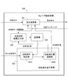
- FIG. 1 is a block diagram showing a configuration example of a control device for a machine tool according to the embodiment of the present disclosure.
- the machine tool control device 10 includes a computerized Numerical Control unit 100, a master axis control unit 200, and a slave axis control unit 300.
- the master shaft control unit 200 drives the motor 400 of the master shaft of the machine tool
- the slave shaft control unit 300 drives the motor 500 of the slave shaft of the machine tool.
- the computer numerical control unit (hereinafter referred to as CNC unit) 100 controls the master axis control unit 200 and the slave axis control unit 300 based on the machining program, and the master axis control unit 200 and the slave axis control unit 300 control the master axis control unit 200 and the slave axis control unit 300. Machining is performed by driving the motor 400 and the motor 500, respectively.
- the machine tool controlled by the control device 10 is, for example, a 3-axis machine tool.
- the machine tool is not limited to the 3-axis machine tool, and may be, for example, a 5-axis machine tool. Since the configuration of the machine tool is already known, FIG. 1 shows only the motors 400 and 500 of the machine tool, and the illustration of other constituent members is omitted.
- the master shaft is, for example, a spindle on which a tool is attached and rotated, and includes a motor.
- the slave shaft is, for example, a tool for processing a work piece or a feed shaft that gives a feed motion to the work piece, and includes a motor.
- the numerical control unit includes a CNC unit, and the CNC unit refers to a numerical control unit that performs numerical control by a computer among the numerical control units.
- FIG. 1 shows only one slave axis control unit 300 and one motor 500 of the control device 10 that performs synchronous operation in the master-slave system, but when the machine tool is a three-axis machine tool, it is shown.
- the feed axis serving as the slave axis is the X axis, the Y axis, and the Z axis, and a control unit and a motor for controlling the feed axis are provided for the X axis, the Y axis, and the Z axis, respectively.
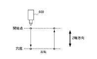
- FIG. 2 is an explanatory diagram showing a tapping operation in screw machining in the Z-axis direction.
- the CNC unit 100 of the control device 10 generates a feed command as a slave shaft command so that the master shaft 600 to which the tap tool is attached moves to the start point of screwing of the workpiece. Then, in the CNC portion 100, the tap tool attached to the tip of the master shaft 600 reaches the bottom of the screw hole from the start point of screwing of the workpiece, and the feed direction (Z-axis direction) and the rotation direction are reversed.
- a feed command as a slave axis command and a rotation command as a master axis command are generated according to the pitch of the screw so that the tap tool moves from the bottom of the screw hole to the start point.
- the control device 10 has a slave shaft command and a rotation amount of the motor 400 of the master shaft which is position feedback information so that the feed amount and the rotation amount of the tap tool at the tip of the master shaft 600 do not deviate from each other at the time of inversion.
- the rotation of the motor 500 of the slave shaft is controlled based on the above, and the feed amount of the tap tool is adjusted. In this way, the control device 10 controls the motor 400 and the motor 500 in synchronization with each other.
- the CNC unit 100 includes a master axis command unit 101, a program analysis unit 102, a synchronization ratio multiplication unit 103, a slave axis command unit 104, and a preceding inversion command unit 105.
- the master axis command unit 101 generates a master axis command for commanding the rotation of the master axis based on the first movement command for commanding the rotation of the master axis, which is output from the program analysis unit 102, and the master axis command unit 101 generates the master axis command.
- the command is output to the command calculation unit 201 of the master axis control unit 200.
- the master axis command includes a rotation direction polarity (forward or reverse) of the master axis 600, and includes a reversal command (which is the first reversal command) including information on rotation speed and / or acceleration and the like.
- the program analysis unit 102 sequentially reads and analyzes blocks including spindle rotation data and Z-axis movement data from a machining program (NC data) created by a CAM (Computer Aided Manufacturing) device. Then, the program analysis unit 102 creates a first movement command for commanding the rotation of the master axis and a second movement command for commanding the movement of the Z axis as the slave axis based on the analysis result, and the second movement command is created.
- the movement command of 1 and the second movement command are output to the master axis command unit 101 and the synchronization ratio multiplication unit 103 as analysis results, respectively.
- the program analysis unit 102 Prior to sending the first movement command to the master axis command unit 101, the program analysis unit 102 commands the rotation of the master shaft at the time of inversion, which is included in the first movement command for commanding the rotation of the master shaft.
- the movement command to be performed is output to the preceding inversion command unit 105.
- the synchronization ratio multiplication unit 103 multiplies the second movement command by the synchronization ratio and outputs it to the slave axis command unit 104.
- the movement of the slave shaft may be required to follow the movement of the master shaft at a ratio other than 1: 1.
- the synchronization ratio multiplication unit 103 multiplies this ratio by the second movement command as the "synchronization ratio".
- the synchronization ratio is specified by the user by describing it in the program, or is specified in advance as a parameter of the CNC unit 100.
- the slave axis command unit 104 moves the Z axis based on the second movement command output by the synchronization ratio multiplication unit 103 multiplied by the synchronization ratio and the position feedback information that is the position detection amount of the motor 400.
- the slave axis command to be commanded is generated, and the slave axis command is output to the command calculation unit 301 of the slave axis control unit 300 of the Z axis.
- the slave axis command includes a polarity (forward or reverse) in the movement direction of the slave axis, and includes a reversal command (which becomes a second reversal command) including information on rotation speed and / or acceleration.
- the advance inversion command unit 105 When the advance inversion command unit 105 receives a movement command from the program analysis unit 102 to instruct the rotation of the master shaft at the time of inversion, the advance inversion command unit 105 sends a advance inversion command to the slave axis control unit 300.
- the pre-reversal command includes the polarity (forward or reverse) of the master shaft 600 and includes information about rotational speed and / or acceleration and the like.
- the program analysis unit 102 before the program analysis unit 102 sends the first movement command to the master axis command unit 101, the program analysis unit 102 outputs a movement command for instructing the rotation of the master axis at the time of reversal to the preceding reversal command unit 105. Therefore, the leading / reversing command unit 105 can output the leading / reversing command to the slave axis control unit 300 before the master axis commanding unit 101 outputs the master axis command including the reversing command.
- the master axis control unit 200 includes a command calculation unit 201.
- the command calculation unit 201 obtains a difference (position deviation) between the position command and the position feedback information from the motor 400.
- the command calculation unit 201 obtains a speed command based on the obtained position deviation, and obtains a torque command based on the obtained speed command. Further, the command calculation unit 201 obtains a current command based on the obtained torque command, and controls the rotational operation of the motor 400.
- the position feedback information is output to the slave axis command unit 104. Since the configuration and operation of the command calculation unit 201 are already known, the illustration and detailed description of the configuration unit of the command calculation unit 201 will be omitted.
- the slave axis control unit 300 includes a command calculation unit 301, an inversion tracking information output unit 302, an inversion correction amount calculation unit 303, and a storage unit 304.
- the slave axis control unit 300 serves as a slave axis control device.
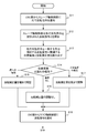
- FIG. 3 is a block diagram showing the configuration of the slave axis control unit.
- the command calculation unit 301 obtains the difference (position deviation) between the position command and the position feedback information from the motor 500.
- the command calculation unit 301 obtains a speed command based on the obtained position deviation, and obtains a torque command based on the obtained speed command. Further, the command calculation unit 301 obtains a current command based on the obtained torque command and controls the rotational operation of the motor 500. Since the configuration and operation of the command calculation unit 301 are already known, the illustration and detailed description of the configuration unit of the command calculation unit 301 will be omitted.
- the inversion tracking information output unit 302 acquires an inversion correction amount calculated based on the preceding inversion command from the inversion correction amount calculation unit 303. Further, the inversion tracking information output unit 302 acquires the inversion command and the position deviation resulting from the inversion tracking result based on the inversion command from the command calculation unit 301.
- the inversion tracking information output unit 302 can detect the inversion of the polarity of the slave axis command input to the command calculation unit 301 to obtain the inversion time, and can detect information such as speed and / or acceleration at the time of inversion. .. Then, the inversion tracking information output unit 302 stores the inversion command, the position deviation, and the inversion correction amount in the storage unit 304 in association with each other.
- the position deviation and the inversion correction amount are inversion tracking information.
- Information such as speed and acceleration is stored as the inversion command.
- the inversion tracking result is not limited to the position deviation, and other information such as velocity deviation may be used.
- the velocity deviation is the difference between the velocity command and the derivative value of the position feedback information.
- the storage unit 304 contains a set of information of the past inversion command before the advance inversion command is input to the slave axis control unit 300, the inversion correction amount for the past inversion command, and the position deviation that is the inversion tracking result. It will be remembered. For example, the storage unit 304 stores n sets of information on the inversion command, the inversion correction amount, and the position deviation (n is a natural number).
- the inversion correction amount calculation unit 303 includes an inversion command collation unit 3031 and an inversion correction amount adjustment unit 3033.
- the reversal command collating unit 3031 receives a predecessor reversal command from the predecessor reversal command unit 105, at least one of the speed and acceleration at the time of reversal included in the predecessor reversal command and the speed of the reversal command stored in the storage unit 304.
- the information of at least one of the acceleration and the acceleration is collated, and the reversal command closest to the preceding reversal command is searched for.
- the inversion command collating unit 3031 reads out the position deviation and the inversion correction amount related to the searched inversion command from the storage unit 304, and outputs the read position deviation and the inversion correction amount to the inversion correction amount adjusting unit 3032.
- the inversion correction amount adjusting unit 3032 determines whether or not the position deviation has a delayed polarity, and if the position deviation has a delayed polarity, adjusts so that the inversion correction amount increases, and if the position deviation has an excessive polarity. Adjusts the inversion correction amount so as to decrease, and outputs the adjusted inversion correction amount to the command calculation unit 301 and the inversion tracking information output unit 302.
- the value for adjusting the inversion correction amount can be determined based on the value of the position deviation or can be set in advance to a predetermined value.
- the inversion correction amount input to the command calculation unit 301 is applied to the acceleration or torque correction in the command calculation unit 301.
- the inversion correction amount input to the command calculation unit 301 may be applied to the correction of the position, the position deviation or the speed.
- the motor 400 of the master shaft rotates the shaft to which the tap tool is attached.
- the slave shaft motor 500 moves the tap tool or the workpiece in the Z-axis direction.
- the movement in the Z-axis direction may use a rotating motor and a ball screw, or a linear motor may be used.
- control device 10 includes an arithmetic processing unit (CPU) or the like. Further, the control device 10 is a temporary storage device such as an HDD (Hard Disk Drive) that stores various control programs such as application software or an OS (Operating System), or an arithmetic processing device for executing a program. It also has a main storage device such as a RAM (Random Access Memory) for storing the data required for the device.
- arithmetic processing unit CPU
- control device 10 is a temporary storage device such as an HDD (Hard Disk Drive) that stores various control programs such as application software or an OS (Operating System), or an arithmetic processing device for executing a program. It also has a main storage device such as a RAM (Random Access Memory) for storing the data required for the device.
- RAM Random Access Memory
- the arithmetic processing device reads the application software or the OS from the auxiliary storage device, and while deploying the read application software or the OS to the main storage device, performs arithmetic processing based on these application software or the OS. .. Further, based on the calculation result, various hardware included in each device is controlled. Thereby, the functional block of this embodiment is realized. That is, this embodiment can be realized by the cooperation of hardware and software.
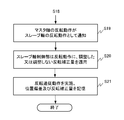
- step S11 the CNC unit 100 notifies the slave axis control unit 300 of the advance inversion command.
- the leading inversion command includes the polarity (forward or reverse) of the master shaft 600, and includes information on the rotation speed and / or acceleration at the time of inversion.
- step S12 the reversal command collation unit 3031 of the slave axis control unit 300 collates the preceding reversal command with the stored reversal command.
- the stored reversal command includes information such as speed and / or acceleration at the time of reversal of the slave axis.
- step S13 the inversion command collating unit 3031 determines the position deviation associated with the inversion command in which at least one of the inversion speed and acceleration of the preceding inversion command matches or is similar to at least one of the inversion speed and acceleration. Read out the inversion correction amount.
- step S14 the inversion correction amount adjusting unit 3032 determines whether or not there is a position deviation, whether or not the position deviation has a delayed polarity, and whether or not the position deviation has an excessive polarity. If the position deviation has a delayed polarity, the inversion correction amount adjusting unit 3032 adjusts the inversion correction amount by increasing in step S15, and if there is no position deviation, the inversion correction amount is used as it is in step S16 (inversion). If the position deviation has an excessive polarity), the inversion correction amount is adjusted by decreasing in step S17.
- step S18 the CNC unit 100 notifies the master axis control unit 200 of the reversal command.
- step S19 the position feedback of the master axis is input to the slave axis command unit 104, the reversal operation of the master axis is reflected in the reversal command of the slave axis, and the reversal command is transmitted from the slave axis command unit 104 to the slave axis control unit 300. It is output to the command calculation unit 301.
- step S20 the slave axis control unit 300 applies the inversion correction amount adjusted or not adjusted by the inversion correction amount adjusting unit 3032 in steps S15 to S17 to the inversion operation in the command calculation unit 301.
- step S21 the command calculation unit 301 of the slave axis control unit 300 controls the motor 500 by applying the inversion correction amount to perform the inversion follow-up operation of the slave axis with respect to the master axis, and the inversion follow-up information output unit 302 , Inversion command, position deviation resulting in inversion tracking result, and inversion correction amount are stored.
- control device 10 can realize all or part of its functions by software.
- the function of the control device 10 can be realized by hardware or a combination of software and hardware.
- what is realized by software means that it is realized by a computer reading and executing a program.
- the control device 10 is composed of hardware, a part or all of each component of the control device 10 is, for example, an LSI (Large Scale Integrated circuit), an ASIC (Application Specific Integrated Circuit), a gate array, or an FPGA (Field). It can be configured by an integrated circuit (IC) such as Programmable Gate Array).
- IC integrated circuit
- control device 10 When the control device 10 is realized by software, according to the control application stored in the first storage unit such as the hard disk device and the ROM, which describes the operation as shown in FIGS. 4 and 5, which operates the control device 10.
- the operation of the control device 10 can be executed by a program by storing the information necessary for the calculation in a second storage unit such as a RAM and executing the processing by the CPU.
- the control application can read the program from a computer-readable medium in which the program is recorded into a first storage unit such as a hard disk.
- Computer-readable media include various types of tangible storage mediums.
- Computer-readable media include non-transitory computer readable medium.
- Examples of computer-readable media include magnetic recording media (eg, hard disk drives), magneto-optical recording media (eg, magneto-optical disks), CD-ROMs (Read Only Memory), CD-Rs, CD-R / Ws, semiconductors. Includes memory (for example, mask ROM, PROM (Programmable ROM), EPROM (Erasable PROM), flash ROM, RAM (random access memory)).
- control device, control method, and slave axis control device can take various embodiments having the following configurations, including the above-described embodiment.
- a control device for a machine tool including a master axis and a slave axis, which performs synchronous operation in a master / slave system.
- a master axis control unit that controls the rotation operation of the master axis
- the slave axis control unit that controls the feed operation of the slave axis
- a master axis command unit that outputs a first reversal command to the master axis control unit based on a machining program, and a second reversal that follows the feedback information based on the machining program and feedback information from the master axis.
- a slave axis command unit that outputs a command to the slave axis control unit, and a pre-reversal command unit that outputs a pre-reversal command to the slave axis control unit prior to the output of the first reversal command to the master axis control unit.
- Numerical control unit and Equipped with The slave axis control unit A storage unit that stores the second inversion command, the follow-up result for the second inversion command, and the inversion correction amount for the second inversion command in association with each other.
- the tracking result and the inversion correction amount associated with the second inversion command stored in the storage unit specified based on the preceding inversion command are output after the output of the preceding inversion command.
- a control device including a reversal correction amount calculation unit for obtaining a reversal correction amount for a second reversal command.
- this control device it is possible to improve the followability of the slave axis with respect to the master axis and improve the synchronization accuracy.
- a control method for a machine tool control device including a master axis and a slave axis, which performs synchronous operation in a master / slave system.
- the control device includes a master axis control unit that controls the rotational operation of the master axis.
- the slave axis control unit that controls the feed operation of the slave axis,
- a first inversion command is output to the master axis control unit based on the machining program, and a second inversion command following the feedback information is issued to the slave based on the machining program and the feedback information from the master axis.
- Numerical control unit that outputs to the axis control unit and Equipped with The slave axis control unit stores the second inversion command, the follow-up result for the second inversion command, and the inversion correction amount for the second inversion command in the storage unit in association with each other. After the second inversion command, the tracking result, and the inversion correction amount are stored in the storage unit, the numerical control unit receives the slave prior to the output of the first inversion command to the master axis control unit. Outputs a leading inversion command to the axis control unit and outputs it to the axis control unit.
- the slave axis control unit uses the tracking result and the reversal correction amount associated with the second reversal command stored in the storage unit specified based on the pre-reversal command to obtain the pre-reversal command.
- a master shaft control unit that controls the rotational operation of the master shaft of the machine tool
- a slave shaft control unit that controls the feed operation of the slave shaft of the machine tool
- a master axis command unit that outputs a first reversal command to the master axis control unit based on a machining program, and a second reversal that follows the feedback information based on the machining program and feedback information from the master axis.
- a slave axis command unit that outputs a command to the slave axis control unit, and a pre-reversal command unit that outputs a pre-reversal command to the slave axis control unit prior to the output of the first reversal command to the master axis control unit.
- Numerical control unit and A slave axis control device that serves as a slave axis control unit of a control device equipped with A storage unit that stores the second inversion command, the follow-up result for the second inversion command, and the inversion correction amount for the second inversion command in association with each other.
- the tracking result and the inversion correction amount associated with the second inversion command stored in the storage unit specified based on the preceding inversion command are output after the output of the preceding inversion command.
- a slave axis control device including an inversion correction amount calculation unit for obtaining an inversion correction amount for a second inversion command.
- this slave axis control device it is possible to improve the followability of the slave axis with respect to the master axis and improve the synchronization accuracy.
- Control device 100 CNC unit 101 Master axis command unit 102 Program analysis unit 103 Synchronous ratio multiplication unit 104 Slave axis command unit 105 Leading reversal command unit 200 Master axis control unit 201 Command calculation unit 300 Slave axis control unit 301 Command calculation unit 302 Inversion Follow-up information output unit 303 Inversion correction amount calculation unit 304 Storage unit 400 Master axis motor 500 Slave axis motor
Landscapes
- Engineering & Computer Science (AREA)
- Human Computer Interaction (AREA)
- Manufacturing & Machinery (AREA)
- Physics & Mathematics (AREA)
- General Physics & Mathematics (AREA)
- Automation & Control Theory (AREA)
- Numerical Control (AREA)
- Automatic Control Of Machine Tools (AREA)
Abstract
Description
前記マスタ軸の回転動作を制御するマスタ軸制御部と、
前記スレーブ軸の送り動作を制御するスレーブ軸制御部と、
加工プログラムに基づいて第1の反転指令を前記マスタ軸制御部に出力するマスタ軸指令部、前記加工プログラムと前記マスタ軸からのフィードバック情報とに基づいて、前記フィードバック情報に追従する第2の反転指令を前記スレーブ軸制御部に出力するスレーブ軸指令部、及び前記マスタ軸制御部への前記第1の反転指令の出力に先だって前記スレーブ軸制御部に先行反転指令を出力する先行反転指令部を有する数値制御部と、
を備え、
前記スレーブ軸制御部は、
前記第2の反転指令、前記第2の反転指令に対する追従結果、及び前記第2の反転指令に対する反転補正量を関連付けて記憶する記憶部と、
前記先行反転指令に基づいて特定される前記記憶部に記憶された前記第2の反転指令に関連づけられた、前記追従結果と前記反転補正量とから、前記先行反転指令の出力後に出力される前記第2の反転指令に対する反転補正量を求める反転補正量計算部とを備える、制御装置である。
前記制御装置は、前記マスタ軸の回転動作を制御するマスタ軸制御部と、
前記スレーブ軸の送り動作を制御するスレーブ軸制御部と、
加工プログラムに基づいて第1の反転指令を前記マスタ軸制御部に出力し、前記加工プログラムと前記マスタ軸からのフィードバック情報とに基づいて、前記フィードバック情報に追従する第2の反転指令を前記スレーブ軸制御部に出力する数値制御部と、
を備え、
前記スレーブ軸制御部は、前記第2の反転指令、前記第2の反転指令に対する追従結果、及び前記第2の反転指令に対する反転補正量を関連付けて記憶部に記憶し、
前記記憶部に前記第2の反転指令、前記追従結果及び前記反転補正量が記憶された後に、前記数値制御部は、前記マスタ軸制御部への前記第1の反転指令の出力に先だって前記スレーブ軸制御部に先行反転指令を出力し、
前記スレーブ軸制御部は、前記先行反転指令に基づいて特定される前記記憶部に記憶された前記第2の反転指令に関連づけられた、前記追従結果と前記反転補正量とから、前記先行反転指令の出力後に出力される前記第2の反転指令の反転補正量を求める、制御方法である。
前記工作機械のスレーブ軸の送り動作を制御するスレーブ軸制御部と、
加工プログラムに基づいて第1の反転指令を前記マスタ軸制御部に出力するマスタ軸指令部、前記加工プログラムと前記マスタ軸からのフィードバック情報とに基づいて、前記フィードバック情報に追従する第2の反転指令を前記スレーブ軸制御部に出力するスレーブ軸指令部、及び前記マスタ軸制御部への前記第1の反転指令の出力に先だって前記スレーブ軸制御部に先行反転指令を出力する先行反転指令部を有する数値制御部と、
を備えた制御装置のスレーブ軸制御部となるスレーブ軸制御装置であって、
前記第2の反転指令、前記第2の反転指令に対する追従結果、及び前記第2の反転指令に対する反転補正量を関連付けて記憶する記憶部と、
前記先行反転指令に基づいて特定される前記記憶部に記憶された前記第2の反転指令に関連づけられた、前記追従結果と前記反転補正量とから、前記先行反転指令の出力後に出力される前記第2の反転指令に対する反転補正量を求める反転補正量計算部とを備えた、スレーブ軸制御装置である。
図1は、本開示の実施形態の工作機械の制御装置の一構成例を示すブロック図である。
図1に示すように、工作機械の制御装置10は、コンピュータ数値制御部(Computerized Numerical Control unit)100、マスタ軸制御部200、及びスレーブ軸制御部300を備えている。マスタ軸制御部200は工作機械のマスタ軸のモータ400を駆動し、スレーブ軸制御部300は工作機械のスレーブ軸のモータ500を駆動する。制御装置10において、コンピュータ数値制御部(以下、CNC部という)100が加工プログラムに基づいてマスタ軸制御部200及びスレーブ軸制御部300を制御し、マスタ軸制御部200及びスレーブ軸制御部300がそれぞれモータ400及びモータ500を駆動して機械加工を行う。制御装置10によって制御される工作機械は、例えば3軸加工機である。工作機械は3軸加工機に限定されず、例えば5軸加工機でもよい。工作機械の構成は既に知られているので、図1では工作機械のモータ400及び500のみを示し、他の構成部材の図示を省略している。マスタ軸は例えば工具を取り付けて回転させる主軸であり、モータを含む。スレーブ軸は、例えば被加工物に加工を施すための工具又は被加工物に送り運動を与える送り軸であり、モータを含む。
数値制御部は、CNC部を含み、CNC部は、数値制御部のうちコンピュータによって数値制御を行う数値制御部をいう。
CNC部100は、図1に示すように、マスタ軸指令部101、プログラム解析部102、同期比乗算部103、スレーブ軸指令部104、及び先行反転指令部105を備えている。
プログラム解析部102は、マスタ軸指令部101に対して第1の移動指令を送出するに先だって、マスタ軸の回転を指令する第1の移動指令に含まれる、反転時のマスタ軸の回転を指令する移動指令を先行反転指令部105に出力する。
マスタ軸制御部200は指令演算部201を備えている。
指令演算部201は、CNC部100のマスタ軸指令部101から、マスタ軸指令として位置指令が入力されると、位置指令とモータ400からの位置フィードバック情報との差(位置偏差)を求める。指令演算部201は、求めた位置偏差に基づいて速度指令を求め、求めた速度指令に基づいてトルク指令を求める。更に指令演算部201は、求めたトルク指令に基づいて電流指令を求め、モータ400の回転動作を制御する。位置フィードバック情報はスレーブ軸指令部104に出力される。指令演算部201の構成及び動作は既に知られているため、指令演算部201の構成部の図示及び詳細な説明は省略する。
スレーブ軸制御部300は、指令演算部301、反転追従情報出力部302、反転補正量計算部303及び記憶部304を備えている。スレーブ軸制御部300はスレーブ軸制御装置となる。図3はスレーブ軸制御部の構成を示すブロック図である。
そして、反転追従情報出力部302は、反転指令と位置偏差と反転補正量とを関連付けて記憶部304に記憶する。位置偏差と反転補正量は反転追従情報となる。反転指令としては速度、加速度等の情報を記憶する。反転追従結果は位置偏差に限定されず、他の情報、例えば速度偏差を用いてよい。速度偏差は、速度指令と位置フィードバック情報の微分値との差である。
記憶部304には、スレーブ軸制御部300に先行反転指令が入力される前の、過去の反転指令と、過去の反転指令に対する反転補正量及び反転追従結果となる位置偏差との情報の組が記憶される。例えば、記憶部304は、反転指令、反転補正量及び位置偏差の情報の組がn個(nは自然数)記憶されている。
反転指令照合部3031は、先行反転指令部105から先行反転指令を受けると、先行反転指令に含まれる、反転時の速度と加速度との少なくとも一方情報と記憶部304に記憶された反転指令の速度と加速度との少なくとも一方の情報とを照合し、先行反転指令に最も近い反転指令を探す。
そして、反転指令照合部3031は、探した反転指令に関連する位置偏差及び反転補正量を記憶部304から読み出し、読み出した位置偏差及び反転補正量を反転補正量調整部3032に出力する。
反転補正量調整部3032は、位置偏差が遅れの極性かどうかを判断し、位置偏差が遅れの極性の場合は、反転補正量が増加するように調整し、位置偏差が行き過ぎの極性の場合には、反転補正量が減少するように調整し、調整された反転補正量を指令演算部301及び反転追従情報出力部302に出力する。反転補正量を調整する値は、位置偏差の値に基づいて決めたり、所定の値に予め設定することができる。指令演算部301に入力される反転補正量は、指令演算部301において加速度又はトルクの補正に適用される。指令演算部301に入力される反転補正量は、位置、位置偏差又は速度の補正に適用してもよい。
マスタ軸のモータ400は、タップ工具が取り付けられた軸を回転させる。スレーブ軸のモータ500は、タップ工具又は被加工物をZ軸方向に移動させる。Z軸方向の移動は回転するモータとボールねじを用いても、リニアモータを用いてもよい。
これらの機能ブロックを実現するために、制御装置10は、CPU(Central Processing Unit)等の演算処理装置を備える。また、制御装置10は、アプリケーションソフトウェア又はOS(Operating System)等の各種の制御用プログラムを格納したHDD(Hard Disk Drive)等の補助記憶装置や、演算処理装置がプログラムを実行する上で一時的に必要とされるデータを格納するためのRAM(Random Access Memory)といった主記憶装置も備える。
ステップS11において、CNC部100からスレーブ軸制御部300に先行反転指令を通知する。先行反転指令は、マスタ軸600の極性(正転又は逆転)を含み、反転時の回転速度、及び/又は加速度等に関する情報を含んでいる。
ステップS13において、反転指令照合部3031は、先行反転指令の反転時の速度と加速度の少なくとも一方が、反転時の速度と加速度の少なくとも一方と一致する又は類似する反転指令に関連する、位置偏差と反転補正量とを読み出す。
反転補正量調整部3032は、位置偏差が遅れの極性の場合は、ステップS15において、反転補正量を増加で調整し、位置偏差がない場合は、ステップS16において、反転補正量をそのまま用い(反転補正量の調整なし)、位置偏差が行き過ぎの極性である場合は、ステップS17において、反転補正量を減少で調整する。
ステップS19において、マスタ軸の位置フィードバックがスレーブ軸指令部104に入力され、マスタ軸の反転動作がスレーブ軸の反転指令に反映されて、反転指令がスレーブ軸指令部104からスレーブ軸制御部300の指令演算部301に出力される。
ステップS21において、スレーブ軸制御部300の指令演算部301は、反転補正量を適用してモータ500を制御して、マスタ軸に対するスレーブ軸の反転追従動作を実施し、反転追従情報出力部302は、反転指令、反転追従結果となる位置偏差及び反転補正量を記憶する。
前記マスタ軸の回転動作を制御するマスタ軸制御部と、
前記スレーブ軸の送り動作を制御するスレーブ軸制御部と、
加工プログラムに基づいて第1の反転指令を前記マスタ軸制御部に出力するマスタ軸指令部、前記加工プログラムと前記マスタ軸からのフィードバック情報とに基づいて、前記フィードバック情報に追従する第2の反転指令を前記スレーブ軸制御部に出力するスレーブ軸指令部、及び前記マスタ軸制御部への前記第1の反転指令の出力に先だって前記スレーブ軸制御部に先行反転指令を出力する先行反転指令部を有する数値制御部と、
を備え、
前記スレーブ軸制御部は、
前記第2の反転指令、前記第2の反転指令に対する追従結果、及び前記第2の反転指令に対する反転補正量を関連付けて記憶する記憶部と、
前記先行反転指令に基づいて特定される前記記憶部に記憶された前記第2の反転指令に関連づけられた、前記追従結果と前記反転補正量とから、前記先行反転指令の出力後に出力される前記第2の反転指令に対する反転補正量を求める反転補正量計算部とを備える、制御装置。
前記制御装置は、前記マスタ軸の回転動作を制御するマスタ軸制御部と、
前記スレーブ軸の送り動作を制御するスレーブ軸制御部と、
加工プログラムに基づいて第1の反転指令を前記マスタ軸制御部に出力し、前記加工プログラムと前記マスタ軸からのフィードバック情報とに基づいて、前記フィードバック情報に追従する第2の反転指令を前記スレーブ軸制御部に出力する数値制御部と、
を備え、
前記スレーブ軸制御部は、前記第2の反転指令、前記第2の反転指令に対する追従結果、及び前記第2の反転指令に対する反転補正量を関連付けて記憶部に記憶し、
前記記憶部に前記第2の反転指令、前記追従結果及び前記反転補正量が記憶された後に、前記数値制御部は、前記マスタ軸制御部への前記第1の反転指令の出力に先だって前記スレーブ軸制御部に先行反転指令を出力し、
前記スレーブ軸制御部は、前記先行反転指令に基づいて特定される前記記憶部に記憶された前記第2の反転指令に関連づけられた、前記追従結果と前記反転補正量とから、前記先行反転指令の出力後に出力される前記第2の反転指令の反転補正量を求める、制御方法。
前記工作機械のスレーブ軸の送り動作を制御するスレーブ軸制御部と、
加工プログラムに基づいて第1の反転指令を前記マスタ軸制御部に出力するマスタ軸指令部、前記加工プログラムと前記マスタ軸からのフィードバック情報とに基づいて、前記フィードバック情報に追従する第2の反転指令を前記スレーブ軸制御部に出力するスレーブ軸指令部、及び前記マスタ軸制御部への前記第1の反転指令の出力に先だって前記スレーブ軸制御部に先行反転指令を出力する先行反転指令部を有する数値制御部と、
を備えた制御装置のスレーブ軸制御部となるスレーブ軸制御装置であって、
前記第2の反転指令、前記第2の反転指令に対する追従結果、及び前記第2の反転指令に対する反転補正量を関連付けて記憶する記憶部と、
前記先行反転指令に基づいて特定される前記記憶部に記憶された前記第2の反転指令に関連づけられた、前記追従結果と前記反転補正量とから、前記先行反転指令の出力後に出力される前記第2の反転指令に対する反転補正量を求める反転補正量計算部とを備えた、スレーブ軸制御装置。
100 CNC部
101 マスタ軸指令部
102 プログラム解析部
103 同期比乗算部
104 スレーブ軸指令部
105 先行反転指令部
200 マスタ軸制御部
201 指令演算部
300 スレーブ軸制御部
301 指令演算部
302 反転追従情報出力部
303 反転補正量計算部
304 記憶部
400 マスタ軸のモータ
500 スレーブ軸のモータ
Claims (5)
- マスタ・スレーブ方式で同期動作を行う、マスタ軸及びスレーブ軸が含まれる工作機械の制御装置であって、
前記マスタ軸の回転動作を制御するマスタ軸制御部と、
前記スレーブ軸の送り動作を制御するスレーブ軸制御部と、
加工プログラムに基づいて第1の反転指令を前記マスタ軸制御部に出力するマスタ軸指令部、前記加工プログラムと前記マスタ軸からのフィードバック情報とに基づいて、前記フィードバック情報に追従する第2の反転指令を前記スレーブ軸制御部に出力するスレーブ軸指令部、及び前記マスタ軸制御部への前記第1の反転指令の出力に先だって前記スレーブ軸制御部に先行反転指令を出力する先行反転指令部を有する数値制御部と、
を備え、
前記スレーブ軸制御部は、
前記第2の反転指令、前記第2の反転指令に対する追従結果、及び前記第2の反転指令に対する反転補正量を関連付けて記憶する記憶部と、
前記先行反転指令に基づいて特定される前記記憶部に記憶された前記第2の反転指令に関連づけられた、前記追従結果と前記反転補正量とから、前記先行反転指令の出力後に出力される前記第2の反転指令に対する反転補正量を求める反転補正量計算部とを備える、制御装置。 - 前記追従結果は、前記スレーブ軸指令部から出力される位置指令と前記スレーブ軸からのフィードバック情報との差となる位置偏差である、請求項1に記載の制御装置。
- 前記反転補正量は、加速度又はトルクに対する補正量である、請求項1又は2に記載の制御装置。
- マスタ・スレーブ方式で同期動作を行う、マスタ軸及びスレーブ軸が含まれる工作機械の制御装置の制御方法であって、
前記制御装置は、前記マスタ軸の回転動作を制御するマスタ軸制御部と、
前記スレーブ軸の送り動作を制御するスレーブ軸制御部と、
加工プログラムに基づいて第1の反転指令を前記マスタ軸制御部に出力し、前記加工プログラムと前記マスタ軸からのフィードバック情報とに基づいて、前記フィードバック情報に追従する第2の反転指令を前記スレーブ軸制御部に出力する数値制御部と、
を備え、
前記スレーブ軸制御部は、前記第2の反転指令、前記第2の反転指令に対する追従結果、及び前記第2の反転指令に対する反転補正量を関連付けて記憶部に記憶し、
前記記憶部に前記第2の反転指令、前記追従結果及び前記反転補正量が記憶された後に、前記数値制御部は、前記マスタ軸制御部への前記第1の反転指令の出力に先だって前記スレーブ軸制御部に先行反転指令を出力し、
前記スレーブ軸制御部は、前記先行反転指令に基づいて特定される前記記憶部に記憶された前記第2の反転指令に関連づけられた、前記追従結果と前記反転補正量とから、前記先行反転指令の出力後に出力される前記第2の反転指令の反転補正量を求める、制御方法。 - 工作機械のマスタ軸の回転動作を制御するマスタ軸制御部と、
前記工作機械のスレーブ軸の送り動作を制御するスレーブ軸制御部と、
加工プログラムに基づいて第1の反転指令を前記マスタ軸制御部に出力するマスタ軸指令部、前記加工プログラムと前記マスタ軸からのフィードバック情報とに基づいて、前記フィードバック情報に追従する第2の反転指令を前記スレーブ軸制御部に出力するスレーブ軸指令部、及び前記マスタ軸制御部への前記第1の反転指令の出力に先だって前記スレーブ軸制御部に先行反転指令を出力する先行反転指令部を有する数値制御部と、
を備えた制御装置のスレーブ軸制御部となるスレーブ軸制御装置であって、
前記第2の反転指令、前記第2の反転指令に対する追従結果、及び前記第2の反転指令に対する反転補正量を関連付けて記憶する記憶部と、
前記先行反転指令に基づいて特定される前記記憶部に記憶された前記第2の反転指令に関連づけられた、前記追従結果と前記反転補正量とから、前記先行反転指令の出力後に出力される前記第2の反転指令に対する反転補正量を求める反転補正量計算部とを備えた、スレーブ軸制御装置。
Priority Applications (4)
| Application Number | Priority Date | Filing Date | Title |
|---|---|---|---|
| CN202180047739.6A CN115769153B (zh) | 2020-07-10 | 2021-07-05 | 机床的控制装置、控制方法以及从轴控制装置 |
| DE112021003711.0T DE112021003711T5 (de) | 2020-07-10 | 2021-07-05 | Steuervorrichtung und Steuerverfahren für Werkzeugmaschinen und Steuervorrichtung für eine Slave-Welle |
| US18/008,819 US12517489B2 (en) | 2020-07-10 | 2021-07-05 | Control device and control method for machine tool, and slave shaft control device |
| JP2022535309A JP7448658B2 (ja) | 2020-07-10 | 2021-07-05 | 工作機械の制御装置と制御方法及びスレーブ軸制御装置 |
Applications Claiming Priority (2)
| Application Number | Priority Date | Filing Date | Title |
|---|---|---|---|
| JP2020-119000 | 2020-07-10 | ||
| JP2020119000 | 2020-07-10 |
Publications (1)
| Publication Number | Publication Date |
|---|---|
| WO2022009822A1 true WO2022009822A1 (ja) | 2022-01-13 |
Family
ID=79553124
Family Applications (1)
| Application Number | Title | Priority Date | Filing Date |
|---|---|---|---|
| PCT/JP2021/025250 Ceased WO2022009822A1 (ja) | 2020-07-10 | 2021-07-05 | 工作機械の制御装置と制御方法及びスレーブ軸制御装置 |
Country Status (5)
| Country | Link |
|---|---|
| US (1) | US12517489B2 (ja) |
| JP (1) | JP7448658B2 (ja) |
| CN (1) | CN115769153B (ja) |
| DE (1) | DE112021003711T5 (ja) |
| WO (1) | WO2022009822A1 (ja) |
Cited By (1)
| Publication number | Priority date | Publication date | Assignee | Title |
|---|---|---|---|---|
| WO2025013209A1 (ja) * | 2023-07-11 | 2025-01-16 | ファナック株式会社 | 制御装置、及びコンピュータ読み取り可能な記録媒体 |
Citations (5)
| Publication number | Priority date | Publication date | Assignee | Title |
|---|---|---|---|---|
| JPS63245325A (ja) * | 1987-03-31 | 1988-10-12 | Brother Ind Ltd | ねじ加工装置 |
| JP2003181722A (ja) * | 2001-12-18 | 2003-07-02 | Toyoda Mach Works Ltd | タッピング加工装置及びタッピング加工方法 |
| JP2007042068A (ja) * | 2005-07-08 | 2007-02-15 | Fanuc Ltd | サーボ制御装置 |
| JP2013035095A (ja) * | 2011-08-08 | 2013-02-21 | Fanuc Ltd | タッピング加工装置 |
| WO2017221380A1 (ja) * | 2016-06-23 | 2017-12-28 | 三菱電機株式会社 | 数値制御装置 |
Family Cites Families (23)
| Publication number | Priority date | Publication date | Assignee | Title |
|---|---|---|---|---|
| JP2629729B2 (ja) | 1987-08-28 | 1997-07-16 | ブラザー工業株式会社 | ねじ加工装置 |
| JP2906766B2 (ja) | 1991-09-24 | 1999-06-21 | 三菱電機株式会社 | サーボモータの制御装置 |
| US5475291A (en) * | 1992-12-10 | 1995-12-12 | Matsushita Electric Industrial Co., Ltd. | Adjustment device for adjusting control parameters of a servo motor and an adjustment method therefor |
| JP3236449B2 (ja) * | 1994-08-04 | 2001-12-10 | ファナック株式会社 | Acサーボモータの制御方法 |
| JP3887197B2 (ja) * | 2001-10-02 | 2007-02-28 | 株式会社森精機製作所 | Nc工作機械の補正装置 |
| JP3808347B2 (ja) * | 2001-11-06 | 2006-08-09 | Juki株式会社 | マスタスレーブ式xy位置決め制御装置及び電子部品搭載装置 |
| US20040240981A1 (en) * | 2003-05-29 | 2004-12-02 | I-Scan Robotics | Robot stacking system for flat glass |
| JP2005216135A (ja) * | 2004-01-30 | 2005-08-11 | Fanuc Ltd | ねじ切り・ねじ立て加工用制御装置 |
| WO2009057229A1 (ja) * | 2007-11-02 | 2009-05-07 | Makino Milling Machine Co., Ltd. | エラーマップ作成方法及び装置並びにエラーマップ作成機能を有した数値制御工作機械 |
| JP4327894B2 (ja) * | 2007-11-30 | 2009-09-09 | ファナック株式会社 | 5軸加工機を制御する数値制御装置 |
| JP5111589B2 (ja) | 2010-10-27 | 2013-01-09 | 株式会社牧野フライス製作所 | 送り軸反転時の補正方法 |
| JP5314110B2 (ja) * | 2011-11-25 | 2013-10-16 | ファナック株式会社 | マスタ軸とスレーブ軸との同期制御を行うモータ制御装置 |
| WO2016009502A1 (ja) * | 2014-07-16 | 2016-01-21 | ヤマザキマザック 株式会社 | 旋削加工制御装置、および旋削加工支援プログラム |
| JP6321586B2 (ja) * | 2015-07-10 | 2018-05-09 | ファナック株式会社 | 軸移動方向を考慮した誤差補正を可能とする数値制御装置 |
| JP6595273B2 (ja) * | 2015-09-11 | 2019-10-23 | Dmg森精機株式会社 | 数値制御装置 |
| JP5969676B1 (ja) * | 2015-09-30 | 2016-08-17 | ファナック株式会社 | 工作機械の工具補正の頻度を最適化する機械学習装置及び機械学習方法、並びに該機械学習装置を備えた工作機械 |
| JP6551259B2 (ja) * | 2016-02-26 | 2019-07-31 | オムロン株式会社 | マスタ装置、スレーブ装置、エラー監視システム、マスタ装置の制御方法、および制御プログラム |
| US10635089B2 (en) * | 2016-06-09 | 2020-04-28 | Mitsubishi Electric Corporation | Servo control device |
| JP6856469B2 (ja) * | 2017-07-19 | 2021-04-07 | ファナック株式会社 | サーボモータ制御装置 |
| JP2019096219A (ja) * | 2017-11-27 | 2019-06-20 | ファナック株式会社 | 工作機械の制御装置 |
| US11787037B2 (en) * | 2018-04-15 | 2023-10-17 | University Of Tsukuba | Behavior estimation apparatus, behavior estimation method, and behavior estimation program |
| JP7057723B2 (ja) | 2018-06-22 | 2022-04-20 | オークマ株式会社 | 位置制御装置 |
| JP7199566B2 (ja) * | 2019-10-17 | 2023-01-05 | 株式会社Fuji | 搭載装置、及び作業機 |
-
2021
- 2021-07-05 US US18/008,819 patent/US12517489B2/en active Active
- 2021-07-05 CN CN202180047739.6A patent/CN115769153B/zh active Active
- 2021-07-05 WO PCT/JP2021/025250 patent/WO2022009822A1/ja not_active Ceased
- 2021-07-05 JP JP2022535309A patent/JP7448658B2/ja active Active
- 2021-07-05 DE DE112021003711.0T patent/DE112021003711T5/de active Pending
Patent Citations (5)
| Publication number | Priority date | Publication date | Assignee | Title |
|---|---|---|---|---|
| JPS63245325A (ja) * | 1987-03-31 | 1988-10-12 | Brother Ind Ltd | ねじ加工装置 |
| JP2003181722A (ja) * | 2001-12-18 | 2003-07-02 | Toyoda Mach Works Ltd | タッピング加工装置及びタッピング加工方法 |
| JP2007042068A (ja) * | 2005-07-08 | 2007-02-15 | Fanuc Ltd | サーボ制御装置 |
| JP2013035095A (ja) * | 2011-08-08 | 2013-02-21 | Fanuc Ltd | タッピング加工装置 |
| WO2017221380A1 (ja) * | 2016-06-23 | 2017-12-28 | 三菱電機株式会社 | 数値制御装置 |
Cited By (1)
| Publication number | Priority date | Publication date | Assignee | Title |
|---|---|---|---|---|
| WO2025013209A1 (ja) * | 2023-07-11 | 2025-01-16 | ファナック株式会社 | 制御装置、及びコンピュータ読み取り可能な記録媒体 |
Also Published As
| Publication number | Publication date |
|---|---|
| US20230229135A1 (en) | 2023-07-20 |
| JP7448658B2 (ja) | 2024-03-12 |
| CN115769153B (zh) | 2025-04-11 |
| CN115769153A (zh) | 2023-03-07 |
| US12517489B2 (en) | 2026-01-06 |
| JPWO2022009822A1 (ja) | 2022-01-13 |
| DE112021003711T5 (de) | 2023-04-20 |
Similar Documents
| Publication | Publication Date | Title |
|---|---|---|
| JP6740199B2 (ja) | 数値制御装置、cnc工作機械、数値制御方法及び数値制御用プログラム | |
| JP5905158B2 (ja) | 数値制御装置 | |
| JP4361071B2 (ja) | サーボ制御装置 | |
| CN107797515A (zh) | 机床的控制装置、控制方法以及计算机可读介质 | |
| JP2017207806A (ja) | 揺動切削を行う工作機械のサーボ制御装置、制御方法及びコンピュータプログラム | |
| US10866574B2 (en) | Machine tool controller with learning error compensation | |
| WO2012057231A1 (ja) | 送り軸反転時の補正方法 | |
| JP4256353B2 (ja) | サーボ制御装置及びサーボ系の調整方法 | |
| US20200406416A1 (en) | Numerical control device, program recording medium, and control method | |
| TW201634176A (zh) | 工具機及其控制裝置 | |
| JP2019004583A (ja) | 電動機の制御装置 | |
| JP3926739B2 (ja) | ねじ切り加工制御方法及びその装置 | |
| JP2005313280A (ja) | 数値制御装置 | |
| CN100496837C (zh) | 螺纹切削控制方法及其装置 | |
| JP7448658B2 (ja) | 工作機械の制御装置と制御方法及びスレーブ軸制御装置 | |
| JP5494378B2 (ja) | ねじ切り制御方法及びその装置 | |
| CN112241148B (zh) | 机床的控制装置以及控制系统 | |
| US11137737B2 (en) | Numerical control device, program recording medium and control method | |
| JP4709588B2 (ja) | ネジ切削加工制御方法及びその装置 | |
| JP6742943B2 (ja) | 工作機械送り系の制御装置 | |
| JPH08263117A (ja) | 数値制御工作機械のバックラッシ補正装置 | |
| JP7513739B2 (ja) | 加工工具とワークとの間の相対的な位置関係の制御を行う数値制御装置 | |
| US10802464B2 (en) | Numerical controller | |
| JP2017220214A (ja) | 工作機械制御装置、工作機械制御方法及び工作機械制御システム | |
| WO2021241552A1 (ja) | 工作機械の制御装置 |
Legal Events
| Date | Code | Title | Description |
|---|---|---|---|
| 121 | Ep: the epo has been informed by wipo that ep was designated in this application |
Ref document number: 21837136 Country of ref document: EP Kind code of ref document: A1 |
|
| ENP | Entry into the national phase |
Ref document number: 2022535309 Country of ref document: JP Kind code of ref document: A |
|
| 122 | Ep: pct application non-entry in european phase |
Ref document number: 21837136 Country of ref document: EP Kind code of ref document: A1 |
|
| WWG | Wipo information: grant in national office |
Ref document number: 202180047739.6 Country of ref document: CN |
|
| WWG | Wipo information: grant in national office |
Ref document number: 18008819 Country of ref document: US |