WO2022009495A1 - 作業工具及び電動工具 - Google Patents
作業工具及び電動工具 Download PDFInfo
- Publication number
- WO2022009495A1 WO2022009495A1 PCT/JP2021/015588 JP2021015588W WO2022009495A1 WO 2022009495 A1 WO2022009495 A1 WO 2022009495A1 JP 2021015588 W JP2021015588 W JP 2021015588W WO 2022009495 A1 WO2022009495 A1 WO 2022009495A1
- Authority
- WO
- WIPO (PCT)
- Prior art keywords
- operating member
- housing
- work tool
- switch
- motor
- Prior art date
- Legal status (The legal status is an assumption and is not a legal conclusion. Google has not performed a legal analysis and makes no representation as to the accuracy of the status listed.)
- Ceased
Links
Images









Classifications
-
- B—PERFORMING OPERATIONS; TRANSPORTING
- B25—HAND TOOLS; PORTABLE POWER-DRIVEN TOOLS; MANIPULATORS
- B25F—COMBINATION OR MULTI-PURPOSE TOOLS NOT OTHERWISE PROVIDED FOR; DETAILS OR COMPONENTS OF PORTABLE POWER-DRIVEN TOOLS NOT PARTICULARLY RELATED TO THE OPERATIONS PERFORMED AND NOT OTHERWISE PROVIDED FOR
- B25F5/00—Details or components of portable power-driven tools not particularly related to the operations performed and not otherwise provided for
- B25F5/02—Construction of casings, bodies or handles
-
- B—PERFORMING OPERATIONS; TRANSPORTING
- B24—GRINDING; POLISHING
- B24B—MACHINES, DEVICES, OR PROCESSES FOR GRINDING OR POLISHING; DRESSING OR CONDITIONING OF ABRADING SURFACES; FEEDING OF GRINDING, POLISHING, OR LAPPING AGENTS
- B24B23/00—Portable grinding machines, e.g. hand-guided; Accessories therefor
- B24B23/02—Portable grinding machines, e.g. hand-guided; Accessories therefor with rotating grinding tools; Accessories therefor
-
- B—PERFORMING OPERATIONS; TRANSPORTING
- B24—GRINDING; POLISHING
- B24B—MACHINES, DEVICES, OR PROCESSES FOR GRINDING OR POLISHING; DRESSING OR CONDITIONING OF ABRADING SURFACES; FEEDING OF GRINDING, POLISHING, OR LAPPING AGENTS
- B24B23/00—Portable grinding machines, e.g. hand-guided; Accessories therefor
- B24B23/02—Portable grinding machines, e.g. hand-guided; Accessories therefor with rotating grinding tools; Accessories therefor
- B24B23/028—Angle tools
Definitions
- the present invention relates to a tool in which a motor is driven or stopped according to an operation of an operating member.
- the hand-held work tool that performs work using the driving force of the motor is provided with a user interface for the user to turn on / off the operation of the motor.
- a user interface for the user to turn on / off the operation of the motor.
- an operation member that is gripped and operated by a user is known.
- the driving of the motor is started, and when the operating member is returned from the starting position to the initial position, the driving of the motor is stopped.
- the operating member extends long along the lower surfaces of both the motor housing accommodating the motor and the rear cover located behind the motor housing. It is provided in. This operating member extends from approximately half of the rear side of the motor housing to near the rear end of the rear cover. This operating member is urged toward the initial position by the urging member.
- the operating member pivots with the front end portion (that is, the end portion on the motor housing side) of the operating member as a fulcrum against the urging force of the urging member.
- this displacement of the operating member is detected by the switch, the motor is driven, and the tip tool is rotated by the rotational driving force of the motor.
- the grinding machine described in Patent Document 1 leaves room for improving the operability of the operating member.
- the operating member can be operated satisfactorily, but when the user wants to grip a place close to the tip tool, the operability deteriorates.
- the distance between the fulcrum and the gripping position becomes small when the user grips the rear half of the motor housing. Therefore, the stroke amount of the operating member at the grip position becomes small, and the user's feeling of operation is reduced.
- the switch since the switch is switched between the on state and the off state with a small stroke amount, it is difficult for the user to obtain the feeling of switching the on / off state. Moreover, if the stroke amount of the operating member is too small, the switch is unintentionally switched to the off state even if the user slightly loosens the force for gripping the operating member. Therefore, the user needs to grip the operating member more firmly. Further, when it is desired to grip the front side of the motor housing, the operation member cannot be operated because the finger does not reach it.
- the above problem is not limited to the grinding machine of Reference 1, but includes an operating member that extends in the longitudinal direction along the housing and is configured to be pivotal around the pivot axis by being gripped by the user. Common to any work tool.
- This specification discloses work tools.
- This work tool extends in the longitudinal direction of the work tool along the motor, housing, and housing, and is configured to be pivotal around the pivot axis by being gripped by the user, with respect to the pivot axis.
- An operating member exposed from the housing on both the first side and the second side opposite to the first side with respect to the pivot axis, and the operating member pivoting in the first direction to the first starting position.
- a switch configured to detect that it has been moved and to detect that the operating member has been pivoted to the second activation position in the second direction opposite to the first direction.
- the work tool is configured to drive the motor when the switch detects that the operating member has been pivoted to the first starting position, and the operating member is pivoted to the second starting position.
- the motor may be configured to be driven when it is detected by the switch.
- the operating member is exposed from the housing on both the first side with respect to the pivot axis and the second side with respect to the pivot axis (ie, user-grip-operable placement). Therefore, it is possible to secure a certain distance between both ends of the operating member sandwiching the pivot axis and the pivot axis of the operating member. Therefore, the stroke amount of the operating member at the gripping position is secured to some extent in both the case where the user grips and operates the first side of the operating member and the case where the user grips and operates the second side of the operating member. can. Therefore, the operability of the operating member is improved.
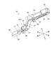
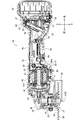
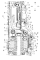
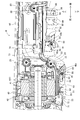
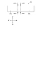
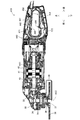
- FIG. It is a partially enlarged view of FIG. It is a partially enlarged view of FIG. It is an exploded view of the grinder and shows the state where the left housing is removed. It is an exploded view of a grinding machine, and shows the state where the left housing and the operation member are removed.
- FIG. 18 is a partially enlarged view. It is a partially enlarged view of FIG.
- a "housing" can be defined as a portion that houses any one or more components selected from the various components of a work tool.
- the operating member may be a single member.
- the operating member may include a first operating member arranged on the first side and a second operating member arranged on the second side.
- the first operating member and the second operating member may have a single pivot axis in common.
- the first operating member may have a first pivot axis and the second operating member may have a second pivot axis.
- the first operating member may be configured to be pivotable around the first pivot axis
- the second operating member may be configured to be pivotable around the second pivot axis. ..
- the first operating member is exposed from the housing on the first side with respect to the first pivot axis and the second pivot axis
- the second operating member is the first pivot axis and the second. It may be exposed from the housing on the second side opposite to the first side with respect to the pivotal axis of.
- the first side may be one side with respect to the pivot axis in the longitudinal direction.
- the second side may be opposite to the first side with respect to the pivot axis in the longitudinal direction.
- the first side may be one side with respect to the pivot axis in the crossing direction intersecting the longitudinal direction.
- the second side may be opposite to the first side with respect to the pivot axis in the crossing direction.
- the switch has a first switch configured to detect that the operating member has been pivoted to a first activation position, and an operating member up to a second activation position. It may include a second switch configured to detect that it has been pivoted. According to this configuration, it is possible to switch the on state / off state of the first switch and the second switch by directly utilizing the pivotal motion of the operating member. In other words, there is no need for a transmission mechanism to transmit the displacement of the operating member to the switch. Therefore, the device configuration can be simplified.
- the first switch may be located on the first side.
- the second switch may be located on the second side. According to this configuration, since it is not necessary to consolidate the first switch and the second switch on one side with respect to the pivot axis, it is easy to set the layout of the work tool that can suppress the increase in size.
- the operating member may include a hinge component that constitutes a portion of the hinge for the operating member to pivot. According to this configuration, the operating member can be held in a predetermined position and can be smoothly pivoted with a simple configuration.
- the hinge component may be a shaft portion that extends in the direction in which the pivot axis extends.
- the shaft portion may be rotatably supported within a boss formed in the housing. According to this configuration, if the housing is divided into half and the like, it is easy to assemble the work tool.
- the hinge component may be a boss portion that surrounds the shaft portion provided in the housing so that the pivot axis extends in the extending direction.
- the operating member may be a single member. According to this configuration, the number of parts is reduced, and a simple device configuration can be obtained. In addition, the operation method becomes easy for the user to understand.
- the work tool has a blocking position that prevents the operating member from being displaced to the first starting position and the operating member from being displaced to the second starting position, and the operating member.
- a lock-off member configured to be displaceable between a permissible position that allows displacement to the first start position and the operating member to be displaced to the second start position may be provided. According to this configuration, it is possible to prevent the motor from being driven against the intention of the user by inadvertently touching the operating member.
- the lockoff member may include a first lockoff member and a second lockoff member.
- the first lock-off member may be configured to pivot integrally with the operating member or may be located on the first side and engage with the housing thereby causing the operating member to be the first. Displacement between a first blocking position that prevents displacement to the starting position and a first permissible position that does not engage the housing and thereby allows the operating member to be displaced to the first starting position. It may be possible.
- the second lock-off member may be configured to pivot integrally with the operating member or may be located on the second side and engage with the housing thereby causing the operating member to be second.
- the lock-off function can be provided with a simple configuration.
- the work tool may include a tip tool configured to be driven by a motor.
- the housing comprises a motor housing that houses the motor and a user-gripable handle housing that is adjacent to the motor housing on the opposite side of the tip tool in the longitudinal direction and extends longitudinally. You may.
- the operating member may include a first portion extending longitudinally along the motor housing and a second portion extending longitudinally along the handle housing.
- the outer peripheral length of the handle housing around the longitudinal direction may be smaller than the outer peripheral length of the motor housing around the longitudinal direction.
- the operating member extends in a direction intersecting the longitudinal direction so as to follow the difference between the outer peripheral length of the handle housing and the outer peripheral length of the motor housing, and has a connecting portion for connecting the first portion and the second portion. You may be prepared.
- the pivot axis may be located at the connecting portion. According to this configuration, since the outer peripheral length of the handle housing and the second portion is relatively small, the user can easily perform the operation of gripping the second portion while gripping the handle housing.
- the user since the user usually does not grasp the boundary between the motor housing and the handle housing (that is, the part of the housing where the outer peripheral length changes), the user according to the present embodiment in which the pivot axis is located at the connecting portion.
- a large distance is secured between the pivot axis and the place where the user grips and operates the operating member in the longitudinal direction. Can be done. Therefore, a large stroke amount of the operating member at the grip position can be secured. That is, good operability of the operating member can be obtained in both the case where the user grips the motor housing and the case where the user grips the handle housing.
- the housing may have an annular portion.
- the operating member may have a ring shape along the inside of the annular portion.
- the pivot axis may be located at the longitudinal end of the operating member. According to this configuration, the number of parts is reduced, and a simple device configuration can be obtained.
- At least one of the first switch and the second switch is the first side end and the second side end of the operating member when the operating member is pivoted. It may be arranged at a position where it is pressed by any of the portions. According to this aspect, the distance between the position where at least one of the first switch and the second switch of the operating member is pressed and the pivot axis is increased. The amount of displacement of the operating member due to the pivot increases as the distance from the pivot axis increases. Therefore, according to this configuration, the amount of displacement required for the operating member to press at least one of the first switch and the second switch to turn on can be increased. Therefore, malfunctions of at least one of the first switch and the second switch are unlikely to occur. Alternatively, the dimensions of the work tool or the required accuracy of assembly can be reduced.
- the power tool houses a motor, a power transmission mechanism connected to the motor, a motor housing that houses the motor, a user-gripable handle housing, and a power transmission mechanism. It may include a gear housing, a tip tool holding portion connected to a power transmission mechanism, and an operating member.
- the operating member extends in the longitudinal direction of the work tool along the motor housing and the handle housing, has a rotation center, and is configured to be rotatable around the rotation center by being gripped by the user. You may.
- the handle housing may have a smaller diameter than the motor housing, and may include a connecting portion for connecting the handle housing and the motor housing.
- the power tool may be configured such that the center of rotation is provided at the connecting portion.
- this power tool allows the user to grip the handle housing and the user to grip the motor housing in the longitudinal direction.
- this power tool allows the user to grip the handle housing and the user to grip the motor housing in the longitudinal direction.
- the handle housing may be eccentric upward with respect to the motor housing.
- the center of rotation may be provided at the bottom of the connecting portion. According to this configuration, it is easy to grip the operating member.
- the operating member may include a first portion and a second portion.
- the first portion has a first end located on the first side with respect to the center of rotation in the longitudinal direction and may extend longitudinally along the motor housing.
- the second portion has a second end located on the second side opposite to the first side in the longitudinal direction with respect to the center of rotation and extends longitudinally along the handle housing. May be good.
- the first portion may have a shape in which the amount of protrusion of the first portion from the motor housing is maximized at the first end portion.
- the second portion may have a shape in which the amount of protrusion of the second portion from the handle housing is maximized at the second end.
- the direction of is closer to the horizontal direction. Therefore, the operation feeling of the user in the state where the operation member is grasped is improved. That is, the user can easily maintain the state of holding the operating member, that is, the state of driving the motor.
- a hand-held electric disc grinding machine (hereinafter, simply referred to as a grinding machine) will be exemplified as a work tool.
- a hand-held electric disc grinding machine (hereinafter, simply referred to as a grinding machine) is exemplified as a work tool including a housing, a motor, and an operating member.
- the grinder 10 is configured to rotationally drive a substantially disk-shaped tip tool 38 mounted on the spindle 35.
- the spindle 35 is rotated by the rotational driving force provided by the electric motor 41.
- a grindstone, a rubber pad, a brush, a blade, and the like are prepared.
- the user selects an appropriate tip tool 38 according to the desired machining operation and attaches it to the grinder 10.
- processing work such as grinding, polishing, and cutting can be performed on the work piece according to the type of the tip tool 38.
- the direction in which the rotation axis AX1 (in other words, the motor shaft 42) of the electric motor 41 extends is defined as the front-rear direction of the grinder 10.
- the side where the tip tool 38 is located is defined as the front side, and the opposite side is defined as the rear side.
- the anteroposterior direction of the grinder 10 can also be defined as the longitudinal direction of the grinder 10.
- the direction in which the rotation axis AX2 of the spindle 35 (in other words, the rotation axis of the tip tool 38) extends is defined as the vertical direction of the grinder 10. In the vertical direction, the side where the tip tool 38 is located is defined as the lower side, and the opposite side is defined as the upper side.
- the directions orthogonal to the vertical direction and the front-back direction are defined as the left-right direction of the grinder 10.
- the right side when the front side is viewed from the rear side is defined as the right side of the grinder 10
- the opposite side is defined as the left side of the grinder 10.
- the grinder 10 includes a housing 15.
- the housing 15 includes a metal gear housing 30 and a resin main body housing 20.
- a power transmission mechanism for transmitting the rotational driving force of the electric motor 41 to the tip tool 38 is housed in the gear housing 30.
- a small bevel gear 33, a large bevel gear 34, and a spindle 35 are housed in the gear housing 30 as a power transmission mechanism.
- the small bevel gear 33 is fixed around the motor shaft 42 at the front end of the motor shaft 42 of the electric motor 41.
- the spindle 35 is rotatably supported around the rotation axis AX2 by bearings arranged apart from each other in the vertical direction.
- the rotation axis AX2 intersects (more specifically, orthogonally) with the rotation axis AX1 of the electric motor 41.
- the large bevel gear 34 is fixed around the spindle 35 on the upper side of the spindle 35 and meshes with the small bevel gear 33.
- a resin or metal bearing box 32 that supports a bearing that rotatably supports the spindle 35 is attached to the lower portion of the gear housing 30.
- the bearing box 32 has a cylindrical shape extending in the vertical direction, and a cover 39 is detachably attached to the outer periphery thereof. The cover 39 covers the rear half of the tip tool 38.
- the spindle 35 extends vertically in the gear housing 30 and extends from the gear housing 30 on the lower side.
- a tip tool holding portion having an inner flange 36 and a locknut 37 is connected to the spindle 35.
- an inner flange 36 is attached around the spindle 35 at the lower end of the spindle 35 extending from the gear housing 30.
- a male threaded portion is formed below the inner flange 36 of the spindle 35, and a locknut 37 is attached to the male threaded portion.
- the main body housing 20 is arranged behind the gear housing 30.
- the body housing 20 is coupled to the gear housing 30 by a plurality of screws or bolts 24 (see FIGS. 1 and 2).
- the main body housing 20 is configured to be divisible in the left-right direction.
- a plurality of screw bosses 22 are formed on the right housing 20a and the left housing 20b, which are half-split bodies.
- the main body housing 20 is formed by connecting the right housing 20a and the left housing 20b to each other by a screw or a bolt 23 inserted into the screw boss 22.
- the main body housing 20 includes a motor housing 40, a handle housing 45, and a rear housing 46 (see FIG. 1).
- each of the right housing 20a and the left housing 20b is an integrally molded single member. However, at least a part of them may be formed by connecting a plurality of members.
- the motor housing 40 is adjacent to the gear housing 30 on the rear side of the gear housing 30.
- the motor housing 40 has a cylindrical shape extending in the front-rear direction.
- An electric motor 41 is housed in the motor housing 40.
- the electric motor 41 is driven by a direct current supplied from the battery 48 via the controller 49.
- the electric motor 41 may be driven by AC power supplied from an AC power source.
- the controller 49 controls the drive of the electric motor 41 by controlling the power supplied to the electric motor 41.
- the handle housing 45 is adjacent to the motor housing 40 on the rear side of the motor housing 40 (in other words, on the side opposite to the tip tool 38 in the longitudinal direction of the grinder 10).
- the handle housing 45 is a portion intended to be grasped by the user when using the grinder 10.
- the handle housing 45 has a cylindrical shape extending in the front-rear direction.
- the outer peripheral length of the handle housing 45 around the front-rear direction is substantially constant.
- the outer peripheral length (in other words, the diameter) of the handle housing 45 is smaller than the outer peripheral length (in other words, the diameter) of the motor housing 40 around the front-rear direction. Therefore, the user can easily grip the handle housing 45.
- the handle housing 45 may have an outer peripheral length equivalent to that of the motor housing 40.
- the upper end of the handle housing 45 is substantially the same as the upper end of the motor housing 40. That is, the handle housing 45 is eccentric upward with respect to the motor housing 40.
- the handle housing 45 is provided with a connecting portion 45a at its front end.
- the connecting portion 45a is a portion that connects the motor housing 40 and the handle housing 45.
- the connecting portion 45a has a diameter that gradually increases toward the front side.
- the rear housing 46 is adjacent to the handle housing 45 behind the handle housing 45.
- the rear housing 46 is a portion having a larger outer circumference around the front-rear direction than the handle housing 45.
- the controller 49 is housed in the rear housing 46.
- a battery mounting portion 47 to which the battery 48 can be attached and detached is provided at the rearmost part of the grinder 10.
- the controller 49 may be disposed within the handle housing 45.
- FIGS. 1 and 3 below the motor housing 40 and the handle housing 45, there is an initial position for stopping the electric motor 41 and a starting position for starting the electric motor 41.
- An operation member 50 configured to be displaceable is provided. The operating member 50 extends in the anteroposterior direction along the body housing 20 (more specifically, along the motor housing 40 and the handle housing 45).
- the operation member 50 is a single member integrally molded, and includes a first portion 51, a second portion 52, and a connecting portion 53.
- the direction display in FIG. 4 indicates the direction when the operating member 50 is assembled to the grinder 10 and is in the initial position.
- the first portion 51 is a portion extending in the front-rear direction along the motor housing 40.
- the second portion 52 is a portion extending in the front-rear direction along the handle housing 45.
- the connecting portion 53 is a portion extending in a direction intersecting the front-rear direction and connecting the first portion 51 and the second portion 52.
- the connecting portion 53 extends so as to follow the difference between the outer peripheral length of the motor housing 40 and the outer peripheral length of the handle housing 45. That is, the connecting portion 53 extends from the rear end of the first portion 51 toward the front end of the second portion 52 so as to approach the rotation axis AX1 of the electric motor 41.
- the first portion 51, the second portion 52, and the connecting portion 53 are all exposed from the main body housing 20 on the lower side thereof (see FIG. 1).
- the connecting portion 53 is provided with two shaft portions 54.
- the two shaft portions 54 extend from the left side surface and the right side surface of the connecting portion 53 toward the outside in the left-right direction, respectively (in FIG. 4, only the shaft portion 54 extending from the left side surface is visible).
- Each of the shaft portions 54 is rotatably supported in a boss 21 (see FIG. 11) formed in the main body housing 20 so as to extend in the left-right direction at the position shown in FIG.
- the operating member 50 can be pivoted around the pivot axis AX3 (which is the central axis of the shaft portion 54 and extends in the left-right direction). That is, the shaft portion 54 functions as a part of the hinge for pivoting the operating member 50. If the pivot of the operating member 50 is realized in the form of a hinge, the operating member 50 can be held in a predetermined position and can be smoothly pivoted with a simple configuration.
- the operating member 50 includes a front end portion 55 and a rear end portion 56.
- An elongated hole 57 is formed in the vicinity of the base end (the end opposite to the front end portion 55) of the first portion 51 so as to penetrate the lower surface of the operating member 50 in the vertical direction.
- an elongated hole 58 is formed in the vicinity of the rear end portion 56 of the second portion 52 so as to penetrate the lower surface of the operating member 50 in the vertical direction.
- a first lock-off member 80 and a second lock-off member 90 extend downward from the elongated holes 57 and 58.
- the first lock-off member 80 is supported by the operating member 50 via a pin 83 extending between the left surface and the right surface of the first portion 51 of the operating member 50 while penetrating the first lock-off member 80. Has been done.
- the first lock-off member 80 is rotatable about the pin 83.
- the second lock-off member 90 is an operating member via a pin 93 extending between the left and right surfaces of the second portion 52 of the operating member 50 while penetrating the second lock-off member 90. Supported by 50.
- the second lock-off member 90 is rotatable about the pin 93. With this configuration, the first lock-off member 80 and the second lock-off member 90 are pivotally pivoted integrally with the operating member 50 when the operating member 50 is pivoted.
- the first lock-off member 80 is arranged on one side (specifically, the front side) in the longitudinal direction with respect to the pivot axis AX3, and the second lock-off member 90 is arranged with respect to the pivot axis AX3. It is arranged on the other side (specifically, the rear side) in the longitudinal direction.
- the operation member 50 includes a first end side region 59 and a second end side region 60.
- the first end side region 59 includes the front end portion 55 and is a region located on the opposite side of the pivot axis AX3 with respect to the first lockoff member 80 in the front-rear direction.
- the second end side region 60 is a region including the rear end portion 56 and located on the side opposite to the pivot axis AX3 with respect to the second lockoff member 90 in the front-rear direction.
- the operating member 50 further includes spring seats 62 and 64.
- the spring seat 62 is located on the front side of the shaft portion 54 in the longitudinal direction (more specifically, between the first lock-off member 80 and the front end portion 55 of the operating member 50).
- the spring seat 64 is located on the rear side of the shaft portion 54 in the longitudinal direction (more specifically, between the second lockoff member 90 and the rear end portion 56 of the operating member 50).
- a spring 63 is arranged around the spring seat 62, and a spring 65 is arranged around the spring seat 64.
- the spring 63 is arranged between the lower surface of the motor housing 40 and the upper surface of the first portion 51 of the operating member 50, and urges the first portion 51 downward.
- the spring 63 urges the operating member 50 in a direction in which the operating member 50 pivots counterclockwise.
- the spring 65 is arranged between the lower surface of the handle housing 45 and the upper surface of the second portion 52 of the operating member 50, and urges the second portion 52 downward. In other words, the spring 65 urges the operating member 50 in a direction in which the operating member 50 is pivoted clockwise.
- the operation member 50 at the initial position can be pivoted clockwise around the pivot axis AX3 by grasping and operating the first portion 51 extending along the motor housing 40, and the handle housing 45. If the user grips and operates the second portion 52 extending along the axis, it can be pivoted counterclockwise around the pivot axis AX3 (in other words, the center of rotation).
- the operation member 50 is provided with the above-mentioned operation member 50.
- the first lock-off member 80 and the second lock-off member 90 are attached.
- the first lock-off member 80 has a first blocking position (see FIG. 7) that prevents the operating member 50 from pivoting clockwise, and a first lock-off member that allows the operating member 50 to pivot clockwise. It is displaceable between the permissible position of 1 (see FIG. 8).
- the first lock-off member 80 includes an operating portion 81 and an engaging portion 82.
- the operation unit 81 projects below the first portion 51 at the first blocking position shown in FIG. 7.
- the engaging portion 82 extends upward on the rear side of the first lockoff member 80.
- a torsion spring 84 is wound around a pin 83 that supports the first lock-off member 80.
- One end of the torsion spring 84 is engaged with the first lock-off member 80, and the other end is engaged with the operating member 50.
- the torsion spring 84 urges the first lockoff member 80 toward the first blocking position shown in FIG. 7 (that is, in the clockwise direction).
- the operating member 50 moves the pivot axis AX3 (that is, the axis). It begins to move clockwise around the central axis of the portion 54).
- the engaging portion 82 of the first lock-off member 80 immediately abuts on the bottom surface 40a of the motor housing 40. Therefore, the operating member 50 can hardly move.
- the first lock-off member 80 has the torsion spring 84 as shown in FIG. It rotates counterclockwise by about 90 degrees against the urging force of, and is displaced to the first allowable position. With this displacement, the engaging portion 82 is oriented so as to extend forward.
- the engaging portion 82 does not abut on the bottom surface 40a, so that the operating member 50 is pivoted clockwise against the urging force of the spring 63. Can move.
- the second lock-off member 90 allows a second blocking position (see FIG. 7) to prevent the operating member 50 from pivoting counterclockwise and allowing the operating member 50 to pivot counterclockwise. It is displaceable between the second permissible position (see FIG. 9).
- the second lock-off member 90 includes an operation portion 91 and an engagement portion 92.
- the operation unit 91 projects below the second portion 52 at the second blocking position shown in FIG. 7.
- the engaging portion 92 extends upward on the rear side of the second lockoff member 90.
- a torsion spring 94 is wound around a pin 93 that supports the second lock-off member 90. One end of the torsion spring 94 is engaged with the second lock-off member 90, and the other end is engaged with the operating member 50. As a result, the torsion spring 94 urges the second lockoff member 90 toward the second blocking position shown in FIG. 7 (that is, in the clockwise direction).
- the operating member 50 moves the pivot axis AX3 (that is, the axis). It begins to move counterclockwise around the central axis of the portion 54).
- the engaging portion 92 of the second lock-off member 90 immediately abuts on the bottom surface 45b of the handle housing 45. Therefore, the operating member 50 can hardly move.
- the second lock-off member 90 has the torsion spring 94 as shown in FIG. It rotates about 90 degrees against the urging force of and is displaced to the second allowable position. With this displacement, the engaging portion 92 is oriented so as to extend forward.
- the engaging portion 92 does not abut on the bottom surface 45b, so that the operating member 50 counterclockwise against the urging force of the spring 65. Can be pivoted.
- the grinder 10 includes a first switch 71 and a second switch 73 in order to detect such a pivotal operation of the operating member 50.
- the first switch 71 and the second switch 73 are microswitches.
- the grinder 10 can be miniaturized.
- the pushing load required for switching from the off state to the on state is smaller than that of the switch used in the conventional grinding machine, so that the user can grip and operate the operation member 50 with a smaller force. Can be done.
- the operability of a conventional grinder in which the pivot axis is located at one end of the operating member and the distance between the other end of the operating member and the pivot axis is relatively large is not impaired.
- the first switch 71 and the second switch 73 may be of any other type (for example, a limit switch) capable of detecting the pivot of the operating member 50.
- the first switch 71 is arranged on the front side with respect to the shaft portion 54 (in other words, the pivot axis AX3), and the second switch 73 is arranged on the rear side with respect to the shaft portion 54. Is located in.
- the first switch 71 includes an actuator portion 72, and the actuator portion 72 is arranged at the bottom of the motor housing 40 so as to project downward.
- the second switch 73 includes an actuator portion 74, and is arranged at the bottom of the handle housing 45 so that the actuator portion 74 projects downward.
- the actuator portion 74 extends downward from a hole formed in the bottom surface 45b of the handle housing 45.
- the operating member 50 pivots clockwise around the pivot axis AX3 (that is, the central axis of the shaft portion 54). Then, when the pivot angle reaches a predetermined amount, the actuator portion 72 of the first switch 71 is pressed by the front end portion 55 of the operating member 50. As a result, the on / off state of the internal contact of the first switch 71 is switched, and the first switch 71 detects the clockwise pivot of the operating member 50.
- the first switch 71 is electrically connected to the controller 49.
- the controller 49 When the controller 49 detects that the clockwise rotation of the operating member 50 is detected by the first switch 71, the controller 49 supplies the electric power from the battery 48 to the electric motor 41, and the electric motor 41 To drive.
- the operating member 50 returns to the initial position by the urging force of the spring 63, and the first lock-off member 80 also pivots together with the operating member 50 and the torsion spring 84 is attached. The force returns to the first blocking position (see Figure 7).
- the controller 49 detects it, stops the supply of electric power to the electric motor 41, and stops the electric motor 41. ..
- the user displaces the second lock-off member 90 from the second blocking position to the second allowable position, and in that state, further grips the second portion 52 of the operating member 50. Then, the operating member 50 pivots counterclockwise around the pivot axis AX3 (that is, the central axis of the shaft portion 54). Then, when the pivot angle reaches a predetermined amount, the actuator portion 74 of the second switch 73 is pressed by the engaging portion 92 of the second lockoff member 90. Since the engaging portion 92 is formed in an arc shape at a portion in contact with the actuator portion 74, the actuator portion 74 can be smoothly pressed.
- the actuator unit 74 When the actuator unit 74 is pressed, the on / off state of the internal contact of the second switch 73 is switched, and the second switch 73 detects the counterclockwise pivot of the operating member 50.
- the second switch 73 is electrically connected to the controller 49.
- the controller 49 detects that the counterclockwise pivot of the operating member 50 is detected by the second switch 73, the controller 49 supplies the electric power from the battery 48 to the electric motor 41 to supply the electric motor. Drive 41.
- the rotation direction of the electric motor 41 at this time is the same as when the clockwise pivot of the operating member 50 is detected by the first switch 71.
- the operating member 50 When the user releases the finger from the operating member 50, the operating member 50 returns to the initial position by the urging force of the spring 65, and the second lock-off member 90 also pivots together with the operating member 50 and the torsion spring 94 is attached. The force returns to the second blocking position (see Figure 7).
- the controller 49 detects it, stops the supply of electric power to the electric motor 41, and stops the electric motor 41. ..
- the electric motor 41 also rotates in the same direction when the operating member 50 is pivoted counterclockwise by grasping and operating the second portion 52 on the rear side with respect to the driving axis AX3.
- the operating member 50 is exposed from the main body housing 20 both on the front side and the rear side with respect to the pivot axis AX3, and the user can use the first portion on the front side with respect to the pivot axis AX3.
- the gripping operation of the operating member 50 can be performed by using the 51 and the second portion 52 on the rear side with respect to the pivot axis AX3, whichever is desired. Since the first portion 51 extends in the front-rear direction along the motor housing 40 and the second portion 52 extends in the front-rear direction along the handle housing 45, the user can grip the motor housing 40. It is possible to grip and operate the operation member 50 both in the case of gripping and in the case of gripping the handle housing 45.
- pivot axis AX3 Since the pivot axis AX3 is located between the front end portion 55 and the rear end portion 56 of the operating member 50, the distance between the pivot axis AX3 and the front end (that is, the front end portion 55) of the first portion 51, and , Both the pivot axis AX3 and the rear end (that is, the rear end 56) of the second portion 52 can be secured to some extent. Therefore, in both the case where the user grips and operates the first portion 51 and the case where the user grips and operates the second portion 52 (in other words, when the user grips the motor housing 40).
- the distance between the grip position and the pivot axis AX3, and by extension, the stroke amount of the operating member 50 at the grip position can be secured to some extent. Therefore, the operability of the operating member 50 is improved. That is, good operability of the operating member 50 can be obtained in both the case where the user grips the motor housing 40 and the case where the user grips the handle housing 45. In other words, good operability of the operating member 50 can be obtained on both the front side and the rear side of the grinder 10.
- the first switch 71 is arranged on the front side with respect to the pivot axis AX3, and the second switch 73 is arranged on the rear side with respect to the pivot axis AX3.
- the switches are concentrated on one side of the pivot axis AX3, it is easier to set the layout of the grinder 10 that can suppress the increase in size.
- a single operating member 50 is configured to pivot clockwise or counterclockwise according to the grip position of the user. Therefore, as compared with the case where the same function is realized by using a plurality of operating members, the number of parts is reduced and the device configuration can be simplified. In addition, the operation method becomes easy for the user to understand.
- the pivot axis AX3 extends in a direction intersecting the front-rear direction of the operating member 50 and connects the first portion 51 and the second portion 52. (In other words, it is located at a place where the outer peripheral length around the front-back direction gradually changes).
- the rotation center of the operating member 50 is provided in the connecting portion 45a connecting the motor housing 40 and the handle housing 45.
- the user selectively grips the motor housing 40 or the handle housing 45 according to his / her preference and the type of work, but the vicinity of the boundary between the motor housing 40 and the handle housing 45 is different from other places. In comparison, it is less likely to be gripped by the user.
- the pivot axis AX3 center of rotation
- the distance between the grip position and the pivot axis AX3 that is, the stroke amount of the operating member 50 at the grip position
- a stroke amount that facilitates switch operation in both the first portion 51 and the second portion 52 (in other words, the amount of protrusion from the main body housing 20 in the rotation direction of the operating member 50). ) Is secured, so that the operation is easy in both the case of gripping the first portion 51 and the case of gripping the second portion 52. Further, since the pivot axis AX3 is arranged between the front end portion 55 and the rear end portion 56, the operation member 50 is prevented from being excessively projected from the product at the [0] grip position. An appropriate stroke amount of 50 can be secured.
- both the front side and the rear side of the operating member 50 are due to the position of the pivot axis AX3 between the front end portion 55 and the rear end portion 56.
- an appropriate amount of protrusion can be secured. That is, good operability can be obtained on both the front side and the rear side of the operation member 50.
- the pivot axis AX3 is arranged between the first portion 51 and the second portion 52, the pivot axis AX3 at the grip position is used for both the first portion 51 and the second portion 52.
- the distance can be secured appropriately, and the pushing load is not too large to be difficult to push.
- the pushing load is appropriately set for both the first portion 51 and the second portion 52.
- the first switch 71 is arranged so that the actuator portion 72 is pressed against the front end portion 55 of the operating member 50 when the operating member 50 is pivoted clockwise. Therefore, it is possible to secure a large distance between the portion of the operating member 50 that presses the actuator portion 72 and the pivot axis AX3.
- the amount of displacement of the operating member 50 due to pivoting increases as the distance from the pivoting axis AX3 increases. Therefore, the amount of displacement required for the operating member 50 to press the actuator portion 72 and the first switch 71 to be turned on can be increased. Therefore, a malfunction of the first switch 71 is unlikely to occur.
- the second switch 73 has the above embodiment in which the actuator portion 74 is pressed by the engaging portion 92 of the second lockoff member 90 when the operating member 50 is pivoted counterclockwise.
- the actuator portion 74 may be arranged at a position where it is pressed by the rear end portion 56 of the operating member 50 when the operating member 50 is pivoted counterclockwise.
- the second switch 73 is in a position where the actuator portion 74 is pressed by the engaging portion 92 of the second lockoff member 90 when the operating member 50 is pivoted counterclockwise. Have been placed.
- an external force acts on the operating member 50, and the engaging portion 92 of the second lock-off member 90 and the handle housing. Even if the operating member 50 bends with the contact point with the bottom surface 45b of the 45 as a fulcrum, it is possible to prevent the operating member 50 or a part of the second lockoff member 90 from unintentionally pressing the actuator portion 74.
- both the second switch 73 and the second lockoff member 90 may be arranged closer to the rear end portion 56 between the pivot axis AX3 and the rear end portion 56 in the front-rear direction.
- both the first switch 71 and the first lockoff member 80 may be located closer to the front end 55 between the pivot axis AX3 and the front end 55.
- the second switch 73 may be arranged closer to the second lock-off member 90 between the second lock-off member 90 and the rear end portion 56 in the front-rear direction.
- the first switch 71 may be arranged closer to the first lock-off member 80 between the first lock-off member 80 and the front end portion 55 in the front-rear direction.
- the second switch 73 is arranged at a position where it is pressed by the second lock-off member 90 when the operating member 50 is pivoted counterclockwise, the second lock-off member 90 is damaged. Even in this case, it is possible to prevent the electric motor 41 from operating unintentionally.
- the first switch 71 is located at a position pressed by the first lockoff member 80 when the operating member 50 is pivoted clockwise. You may.
- the first switch 71 and the first lockoff member 80 may be arranged in the front-rear direction between the pivot axis AX3 and the front end portion 55 closer to the front end portion 55. According to such an arrangement, the feature that the distance between the first switch 71 and the pivot axis AX3 is large and the feature that the distance between the first switch 71 and the first lock-off member 80 is small. It is compatible. Therefore, the effects of these features described above can be maximized. That is, the malfunction of the first switch 71 can be further suppressed, and the required accuracy of the dimensions or assembly of the grinder 10 can be further lowered.
- the second switch 73 and the second lockoff member 90 may be arranged between the pivot axis AX3 and the rear end 56 closer to the rear end 56.
- the feature that the distance between the second switch 73 and the pivot axis AX3 is large and the feature that the distance between the second switch 73 and the second lockoff member 90 is small are realized. It is compatible. Therefore, the effects of these features described above can be maximized.
- the operating member 50 may have a configuration that is easy to grip in the vicinity of the front end portion 55 or the rear end portion 56.
- the first lock-off member 80 may be arranged closer to the front end portion 55 between the front end portion 55 and the pivot axis AX3 in the front-rear direction
- the second lock-off member 80 may be arranged.
- the member 90 may be arranged closer to the rear end portion 56 between the pivot axis AX3 and the rear end portion 56 in the front-rear direction. Normally, the user grips and operates the operation member 50 with one of the fingers of one hand while rotating the first lock-off member 80 or the second lock-off member 90.
- the location is likely to be in the vicinity of the first lockoff member 80 or the second lockoff member 90.
- the first lock-off member 80 when the user grips and operates the first portion 51, for example, the first lock-off member 80 is rotated by the ring finger or the little finger, and the first end with the index finger and the middle finger. It is conceivable to grip and operate the part side region 59.
- the user grips and operates the second portion 52 when the user grips and operates the second portion 52, for example, the user rotates the second lock-off member 90 with the index finger and the second end with the middle finger and the ring finger. It is conceivable to grip and operate the part side region 60.
- the first lock-off member 80 is arranged closer to the front end portion 55 as described above, the user can easily grip and operate the vicinity of the front end portion 55, and the second lock-off member 90 can be operated as described above. If it is arranged closer to the rear end portion 56, the user can easily grasp the vicinity of the rear end portion 56. With such an arrangement, the distance between the pivot axis AX3 and the grip portion can be further secured. Therefore, according to the principle of the lever, the grip load of the user required to turn on the first switch 71 or the second switch 73 can be reduced, and the operability is improved.
- the first portion 51 located anterior to the pivot axis AX3 has a front end 55 with an amount of protrusion (ie, downward) of the first portion 51 from the motor housing 40. It may have a shape that maximizes at.
- the second portion 52 may have a shape in which the amount of protrusion of the second portion 52 from the handle housing 45 is maximized at the rear end portion 56.
- the first portion 51 has a shape in which the amount of protrusion of the first portion 51 from the motor housing 40 gradually increases toward the front (that is, as the distance from the pivot axis AX3 increases). May be.
- the second portion 52 has a shape in which the amount of protrusion of the second portion 52 from the handle housing 45 gradually increases toward the rear (that is, as the distance from the pivot axis AX3 increases). good.
- the orientation of the exposed portion of the operating member 50 when the user grips the operating member 50 is closer to the horizontal direction.
- the lower surface of the first portion 51 ie, the surface to be gripped by the user
- the lower surface of the second portion 52 may extend in the horizontal direction when the second switch 73 is in the ON state.
- the operating member 150 includes a third portion 155 behind the second portion 52.
- the third portion 155 extends upward from the rear end of the second portion 52, then bends and extends rearward, and is housed inside the main body housing 120.
- a first switch 171 is arranged above the third portion 155, and a second switch 173 is arranged below the third portion 155.
- the third portion 155 presses the first switch 171 and when the operating member 150 is pivoted clockwise, the third portion 155 presses. Press the second switch 173.
- the two switches may be centrally arranged on one side with respect to the pivot axis AX3 in the front-rear direction.
- the operation member 250 includes a first operation member 250a and a second operation member 250b.
- the first operating member 250a extends in the front-rear direction along the motor housing 40 (not shown in FIG. 13), and the second operating member 250b extends back and forth along the handle housing 45 (not shown in FIG. 13). It extends in the direction.
- the first operating member 250a is provided with a boss 255a at its rear end, and the second operating member 250b is provided with a boss 255b at its front end.
- the bosses 255a and 255b are hingedly connected to the shaft portion 225 formed in the main body housing 20.
- the first operating member 250a clockwise around the pivot axis AX3 (which is the central axis of the shaft portion 225 and extends in the left-right direction).
- the second operating member 250b is pivoted counterclockwise around the pivot axis AX3. In this way, two operating members 250a and 250b that can be pivoted in opposite directions about the common pivot axis AX3 may be used.
- the operation member 350 includes a first operation member 350a and a second operation member 350b.
- the first operating member 350a extends in the front-rear direction along the motor housing 40 (not shown in FIG. 14), and the second operating member 350b extends back and forth along the handle housing 45 (not shown in FIG. 14). It extends in the direction.
- the first operating member 350a is provided with a shaft portion 325a at its rear end, and the second operating member 350b is provided with a shaft portion 325b at its front end.
- the shaft portions 325a and 325b are pivotally supported in two bosses formed in the main body housing 20, respectively.
- the first operating member 350a When the user grips and operates the first operating member 350a, the first operating member 350a is centered on the first pivot axis AX4 (which is the central axis of the shaft portion 325a and extends in the left-right direction). It moves clockwise.
- the second operating member 350b holds the second pivot axis AX5 (this is the central axis of the shaft portion 325b and extends in the left-right direction). It moves counterclockwise as the center.
- two operating members 350a and 350b having separate pivot axes AX4 and AX5 may be used.
- the grinding machine 410 includes a handle housing 440 on the rear side of the motor housing 40.
- the handle housing 440 is a hollow member extending in a long shape in the front-rear direction.
- the handle housing 440 is a so-called loop type, and has an annular portion 441 extending in a long shape on the rear side thereof.
- the annular portion 441 is a portion intended to be gripped by the user.
- the annular portion 441 is a portion that surrounds the periphery of the through hole 442 that penetrates the handle housing 440 in the left-right direction, and has a closed ring shape.
- the through hole 442 has a shape in which the width in the vertical direction increases toward the front side when viewed in the left-right direction.
- the annular portion 441 may have an annular shape with an open trailing end.
- the operation member 450 is arranged inside the handle housing 440.
- the operating member 450 is loop-shaped and has a ring shape along the inside of the handle housing 440 (in other words, along the outer shell of the through hole 442).
- the operating member 450 extends in the front-rear direction as the longitudinal direction.
- the inner edge portion of the operating member 450 has a substantially oval shape when viewed in the left-right direction.
- the outer edge portion of the operating member 450 has a shape in which the width in the vertical direction increases toward the front side when viewed in the left-right direction.
- the operating member 450 is arranged so as to be entirely exposed from the handle housing 440 (more specifically, the annular portion 441).
- the clearance between the inner edge portion of the annular portion 441 of the handle housing 440 and the main body 451 of the operating member 50 increases toward the front side.
- the main body 451 may have a ring shape with its front end open.
- the operation member 450 includes the main body 451 having the above-mentioned ring shape and the pivot shaft portion 454.
- the pivot shaft portion 454 is arranged so as to project toward the rear side from the main body 451 at the rear end of the main body 451 and at the center in the vertical direction.
- the pivot shaft portion 454 has a cylindrical shape extending in the left-right direction, and a through hole 455 extending in the left-right direction is formed inside the cylindrical shaft portion 454.
- a pin 461 is inserted into the through hole 455 so as to extend in both the left and right directions from the pivot shaft portion 454.
- the pin 461 is supported between the left and right surfaces at the rear end of the annular portion 441, as shown in FIG.
- the operating member 450 is configured to be pivotable about the pin 461 (in other words, about the pivot axis AX3 shown in FIG. 16) as shown in FIGS. 19 and 20. ..
- the operating member 450 intersects in the front-rear direction (in other words, the longitudinal direction of the grinding machine 410) (in the present embodiment). In the vertical direction), it is exposed from the handle housing 440 on both sides (that is, upper and lower sides) with respect to the pivot axis AX3.
- the spring 462 is arranged in a compressed state.
- the spring 462 is arranged in a bottomed hole 456 formed in the upper portion so that horizontal movement is restricted.
- the spring 462 is arranged substantially in the center of the main body 451 in the front-rear direction. With this configuration, the spring 462 urges the operating member 450 downward.
- a spring 463 is arranged in a compressed state between the lower inner edge portion of the annular portion 441 and the portion extending in the front-rear direction on the lower side of the main body 451 (hereinafter, also referred to as a lower portion). Will be done.
- the spring 463 is arranged in a bottomed hole 457 formed in the lower portion so that horizontal movement is restricted.
- the spring 463 is arranged at the same position as the spring 462 in the front-rear direction. With this configuration, the spring 463 urges the operating member 450 upward.
- the operating member 450 is maintained in the vertical direction at the center of the through hole 442 of the annular portion 441. This position is the initial position of the operating member 450 when it is not gripped by the user.
- a protrusion 458 protruding upward is formed near the front end of the upper portion of the main body 451.
- a protrusion 459 protruding downward is formed near the front end of the lower portion of the main body 451.
- the protrusions 458 and 459 are in the same position in the front-rear direction.
- the protrusions 458 and 459 are provided to press the actuator portion 472 of the first switch 471 and the actuator portion 474 of the second switch 473, respectively, when the operating member 450 is pivoted.
- the first switch 471 is attached to the annular portion 441 above the pin 461 (the pivot axis AX3) so that the actuator portion 472 is exposed from the annular portion 441.
- the second switch 473 is attached to the annular portion 441 so that the actuator portion 474 is exposed from the annular portion 441 below the pin 461 (the pivot axis AX3).
- the first switch 471 and the actuator unit 472 are arranged at positions corresponding to the protrusions 458 and 459 of the operating member 450, that is, near the front end of the operating member 450.
- through holes 452 and 453 are formed on the front side of the main body 451.
- the through hole 452 penetrates the upper portion of the main body 451 in the vertical direction.
- the through hole 453 penetrates the lower portion of the main body 451 in the vertical direction.
- a first lock-off member 480 and a second lock-off member 490 are mounted in the through holes 452 and 453, respectively.
- first lock-off member 480 and the second lock-off member 490 have structures similar to those of the first lock-off member 80 and the second lock-off member 90 of the first embodiment, respectively, they have a structure similar to that of the first lock-off member 80 and the second lock-off member 90.
- first lock-off member 480 is attached to the main body 451 via a pin 483 supported by the main body 451.
- the first lock-off member 480 has a first blocking position (see FIG. 20) that prevents the operating member 450 from pivoting clockwise, and a first lock-off member that allows the operating member 450 to pivot clockwise. It is pivotable around pin 483 between the permissible position of 1 (see FIG. 19).
- the first lockoff member 480 is urged in the counterclockwise direction (in other words, toward the first blocking position) by the torsion spring 484.
- the operating portion 481 and the engaging portion 482 project from the lower surface and the upper surface of the upper portion of the main body 451 respectively.
- the second lock-off member 490 is attached to the main body 451 via a pin 493 supported by the main body 451.
- the second lock-off member 490 allows a second blocking position (see FIG. 19) to prevent the operating member 450 from pivoting counterclockwise and allowing the operating member 450 to pivot counterclockwise. It is pivotable around pin 493 between the second permissible position (see FIG. 20).
- the second lockoff member 490 is urged clockwise (in other words, towards the second blocking position) by the torsion spring 494.
- the operating portion 491 and the engaging portion 492 project from the upper surface and the lower surface of the lower portion of the main body 451, respectively.
- the user moves the operation unit 481 of the first lockoff member 480 from the first blocking position (see FIG. 20) to the first allowable position (see FIG. 19).
- the operating member 450 centers on the pin 461 against the urging force of the spring 462. As it moves clockwise. Then, when the operating member 450 is pivoted clockwise to the first starting position, the protrusion 458 of the operating member 450 pushes the actuator portion 472 of the first switch 471 upward and displaces it.
- the first switch 471 that detects this is switched from the off state to the on state, and the electric motor 41 is driven.
- the operating member 450 returns to the initial position by the urging force of the spring 462, and the first lock-off member 480 returns to the first blocking position by the urging force of the torsion spring 484.
- the user pivots the operation unit 491 of the second lockoff member 490 from the second blocking position (see FIG. 19) to the second allowable position (see FIG. 20).
- the operating member 450 counterclockwise around the pin 461 against the urging force of the spring 463. Move around.
- the protrusion 459 of the operating member 450 presses the actuator portion 474 of the second switch 473 downward to displace it.
- the second switch 473 that detects this is switched from the off state to the on state, and the electric motor 41 is driven.
- the rotation direction of the electric motor 41 at this time is the same as when the first switch 471 is turned on.
- the operating member 450 returns to the initial position by the urging force of the spring 463, and the second lock-off member 490 returns to the second blocking position by the urging force of the torsion spring 494.
- the same effect as that of the first embodiment can be obtained.
- the electric motor 41 can be driven by grasping and operating either the portion or the portion. Since the pivot axis AX3 is located between the upper portion and the lower portion, the distance between the pivot axis AX3 and the grip position of the upper portion of the main body 451 and the distance between the pivot axis AX3 and the main body 451 Both the grip position of the side part and the distance can be secured to some extent.
- the radius of gyration of the operating member 450 at the grip position, and by extension, the stroke amount can be secured to some extent. Therefore, good operability of the operating member 450 can be obtained.
- the pin 461 (the pivot axis AX3) is located at the rear end of the operating member 450, and the first switch 471 and the second switch 473 are the operating member 450. It is located at a position corresponding to the front end of the upper part and the lower part. Therefore, the pivot axis AX3 in the front-rear direction and the first switch 471 and the second switch 473 (in other words, the protrusions 458 and 459 that press the first switch 471 and the second switch 473). A large distance can be secured for each of the above. Therefore, the amount of displacement required for the operating member 450 to press the actuator portion 472 or 474 to turn on the first switch 471 or 473 can be increased. Therefore, malfunctions of the first switches 471 and 473 are unlikely to occur.
- the operating member 450 since the pin 461 (driven axis AX3) of the operating member 450 is located at the rear end of the operating member 450, the front side of the operating member 450 relatively far from the driving axis AX3 A greater stroke feeling can be obtained when the grip operation is performed than when the rear side is gripped.
- the first lock-off member 480 and the second lock-off member 490 are located on the front side of the operation member 450, the user grips and operates the front side of the operation member 450, that is, more The user can be guided so that a large stroke feeling can be obtained.
- the pivot axis AX3 may be located near the boundary between the motor housing 40 and the handle housing 45 instead of being located at the connecting portion 53.
- Located near the boundary means, for example, that the area between the end of the motor housing 40 on the opposite side of the handle housing 45 and the boundary is divided into three equal parts in the longitudinal direction to form three areas. It may be defined as being located within the region closest to the boundary when obtained.
- located near the boundary means, for example, that the area between the end of the handle housing 45 opposite to the motor housing 40 and the boundary is divided into three equal parts in the longitudinal direction. It may be defined as being located within the region closest to the boundary when the region is obtained.
- the pivot axis AX3 may be located in the middle region when the operating member 50 is divided into three equal parts in the longitudinal direction to obtain three regions.
- the operating member 50 may include a convex portion that protrudes downward instead of the hinge structure.
- the convex portion may be arranged on the bottom surface of the main body housing 20, and the operating member 50 may be pivoted with the convex portion as a fulcrum.
- the grinder 10 or 450 may include a transmission mechanism configured to transmit the displacement of the operating member 50 or 450 to a single switch.
- This transmission mechanism is configured to displace in conjunction with the clockwise pivot of the operating member 50 or 450 to press a single switch, and the counterclockwise pivot of the operating member 50 or 450. It is configured to displace in conjunction with and press a single switch.
- the transmission mechanism can be implemented by any known mechanical element, such as a link member.
- a single lock-off member engages the operating member 50 or 450 so that the operating member 50 or 450 cannot rotate both clockwise and counterclockwise, and the operating member 50 or 450 of the operating member 50 or 450.
- the blocking position that blocks the pivot and the permissible position that does not engage the operating member 50 or 450 and allows both clockwise and counterclockwise pivoting of the operating member 50 or 450. It may be configured to be displaceable.
- the pivot axis AX3 may be located at the front end of the operating member 450.
- the through hole 442 of the handle housing 440 may have a shape in which the width in the vertical direction increases toward the rear side when viewed in the left-right direction.
- the outer edge portion of the operating member 450 may have a shape in which the width in the vertical direction increases toward the rear side when viewed in the left-right direction.
- the clearance between the inner edge portion of the annular portion 441 of the handle housing 440 and the main body 451 of the operating member 50 may be increased toward the rear side.
- the above-described embodiment is applicable not only to grinders 10 and 410 but also to any work tool provided with a grip-operated operating member extending in a long shape along the housing.
- Torsion spring 120 ... Main body housing 150 ... Operation member 155. .. 3rd part 171 ... 1st switch 173 ... 2nd switch 225 ... Shaft part 250 ... Operating member 250a ... 1st operating member 250b ... 2nd Operation member 255a, 255b ... Bolt 325a, 325b ... Shaft part 350 ... Operation member 350a ... First operation member 350b ... Second operation member 440 ... Handle housing 441 .. Circular portion 442 ... Through hole 451. .. Main body 452,453 ... Through hole 454 ... Pivot shaft part 455 ... Through hole 456,457 ... Hole 458,459 ... Protrusion 461 ... Pin 462,463 ... Spring AX1, AX2 ... Rotating axis AX3 ... Pivot axis AX4 ... First pivot axis AX5 ... Second pivot axis
Landscapes
- Engineering & Computer Science (AREA)
- Mechanical Engineering (AREA)
- Finish Polishing, Edge Sharpening, And Grinding By Specific Grinding Devices (AREA)
- Portable Power Tools In General (AREA)
- Constituent Portions Of Griding Lathes, Driving, Sensing And Control (AREA)
Abstract
作業工具は、モータと、ハウジングと、ハウジングに沿って作業工具の長手方向に延在し、ユーザによって握り操作されることによって枢動軸線を中心として枢動可能に構成され、長手方向における枢動軸線に対する第1の側と第2の側との両方でハウジングから露出された操作部材と、操作部材が第1の起動位置まで第1の方向に枢動されたことを検知するように構成されるとともに、操作部材が第2の起動位置まで第2の方向に枢動されたことを検知するように構成されたスイッチと、を備える。作業工具は、操作部材が第1の起動位置まで枢動されたことがスイッチによって検知された場合にモータが駆動されるように構成されるとともに、操作部材が第2の起動位置まで枢動されたことがスイッチによって検知された場合にモータが駆動されるように構成される。
Description
本発明は、操作部材の操作に応じて、モータが駆動または停止される工具に関する。
モータの駆動力を利用して作業を行う手持ち式の作業工具には、ユーザがモータの動作のオン/オフ操作を行うためのユーザインタフェースが設けられる。このようなユーザインタフェースの一種として、ユーザによって握り操作される操作部材が知られている。ユーザの握り操作によって操作部材が初期位置から起動位置まで変位されると、モータの駆動が開始され、操作部材が起動位置から初期位置に戻されると、モータの駆動が停止される。
例えば、下記の特許文献1が開示するグラインダでは、操作部材が、モータを収容するモータハウジングと、モータハウジングの後方に位置するリアカバーと、の両方の下面に沿って長尺状に延在するように設けられている。この操作部材は、モータハウジングの後側の略半分からリアカバーの後端付近まで延在している。この操作部材は、付勢部材によって初期位置に向けて付勢されている。ユーザが操作部材を握り操作すると、操作部材は、付勢部材による付勢力に抗って、当該操作部材の前端部(つまり、モータハウジング側の端部)を支点として枢動する。操作部材のこの変位がスイッチによって検知されると、モータが駆動され、モータの回転駆動力によって先端工具が回転する。
しかしながら、特許文献1に記載のグラインダは、操作部材の操作性を改善する余地を残している。例えば、ユーザは、リアカバーを把持する場合は、操作部材を良好に操作できるものの、ユーザが先端工具に近いところを把持したい場合は、操作性が悪くなる。具体的には、操作部材は、握り操作されたときに前端部を支点として枢動するので、ユーザがモータハウジングの後側の半分を把持するときには、支点と握り位置との距離が小さくなる。このため、握り位置における操作部材のストローク量が小さくなり、ユーザの操作感が低下する。つまり、僅かなストローク量でスイッチのオン状態とオフ状態とが切り替わるので、ユーザは、オン/オフ状態を切り換えた感覚を得にくい。しかも、操作部材のストローク量が小さ過ぎると、ユーザが操作部材を握る力を少し緩めただけでも、スイッチが意図に反してオフ状態に切り換えられてしまう。このため、ユーザは、操作部材をよりしっかりと握る必要がある。また、モータハウジングの前側を把持したい場合、操作部材に指が届かず操作することができない。上記の問題は、引用文献1のグラインダに限らず、ハウジングに沿って長手方向に延在し、ユーザによって握り操作されることによって枢動軸線を中心として枢動可能に構成された操作部材を備える任意の作業工具に共通する。
本明細書は作業工具を開示する。この作業工具は、モータと、ハウジングと、ハウジングに沿って作業工具の長手方向に延在し、ユーザによって握り操作されることによって枢動軸線を中心として枢動可能に構成され、枢動軸線に対する第1の側と、枢動軸線に対する第1の側と反対の第2の側と、の両方でハウジングから露出された操作部材と、操作部材が第1の起動位置まで第1の方向に枢動されたことを検知するように構成されるとともに、操作部材が第2の起動位置まで第1の方向と反対の第2の方向に枢動されたことを検知するように構成されたスイッチと、を備えていてもよい。作業工具は、操作部材が第1の起動位置まで枢動されたことがスイッチによって検知された場合にモータが駆動されるように構成されるとともに、操作部材が第2の起動位置まで枢動されたことがスイッチによって検知された場合にモータが駆動されるように構成されてもよい。
この作業工具によれば、操作部材は、枢動軸線に対する第1の側と、枢動軸線に対する第2の側と、の両方でハウジングから露出されている(つまり、ユーザが握り操作可能に配置されている)ので、枢動軸線を間に挟む操作部材の両端部と、操作部材の枢動軸線と、のそれぞれの距離をある程度確保できる。したがって、ユーザが操作部材の第1の側を握り操作する場合と、ユーザが操作部材の第2の側を握り操作する場合と、の両方において、握り位置における操作部材のストローク量をある程度、確保できる。したがって、操作部材の操作性が向上する。
「ハウジング」とは、作業工具の様々な構成要素から選択される任意の1つ以上の構成要素を収容する部分として定義され得る。操作部材は単一の部材であってもよい。あるいは、操作部材は、第1の側に配置される第1の操作部材と、第2の側に配置される第2の操作部材と、を備えていてもよい。この場合、第1の操作部材および第2の操作部材は、共通する単一の枢動軸線を有していてもよい。あるいは、第1の操作部材が第1の枢動軸線を有し、第2の操作部材が第2の枢動軸線を有していてもよい。換言すれば、第1の操作部材が第1の枢動軸線を中心として枢動可能に構成され、第2の操作部材が第2の枢動軸線を中心として枢動可能に構成されてもよい。この場合、第1の操作部材は、第1の枢動軸線および第2の枢動軸線に対する第1の側でハウジングから露出され、第2の操作部材は、第1の枢動軸線および第2の枢動軸線に対する第1の側と反対の第2の側でハウジングから露出されていてもよい。
1つまたはそれ以上の実施形態において、第1の側は、長手方向における枢動軸線に対する一方側であってもよい。第2の側は、長手方向における枢動軸線に対する第1の側と反対側であってもよい。この構成によれば、操作部材の長手方向の両端部と、操作部材の枢動軸線と、のそれぞれの距離をある程度確保できる。したがって、ユーザが長手方向における操作部材の第1の側を握り操作する場合と、ユーザが長手方向における操作部材の第2の側を握り操作する場合と、の両方において、握り位置における操作部材のストローク量をある程度、確保できる。また、先端工具に近い位置を把持する場合でも、操作可能な位置に操作部材を配置できる。
1つまたはそれ以上の実施形態において、第1の側は、長手方向と交差する交差方向における枢動軸線に対する一方側であってもよい。第2の側は、交差方向における枢動軸線に対する第1の側と反対側であってもよい。この構成によれば、ユーザが交差方向における操作部材の第1の側を握り操作する場合と、ユーザが交差方向における操作部材の第2の側を握り操作する場合と、の両方において、握り位置における操作部材の回転半径、ひいては、ストローク量をある程度、確保できる。
1つまたはそれ以上の実施形態において、スイッチは、操作部材が第1の起動位置まで枢動されたことを検知するように構成された第1のスイッチと、操作部材が第2の起動位置まで枢動されたことを検知するように構成された第2のスイッチと、を備えていてもよい。この構成によれば、操作部材の枢動運動を直接的に利用して、第1のスイッチおよび第2のスイッチのオン状態/オフ状態の切換えを行うことができる。換言すれば、操作部材の変位をスイッチに伝達する伝達機構が必要ない。したがって、装置構成を簡素化できる。
1つまたはそれ以上の実施形態において、第1のスイッチは、第1の側に配置されていてもよい。第2のスイッチは、第2の側に配置されていてもよい。この構成によれば、第1のスイッチおよび第2のスイッチを枢動軸線に対する一方側に集約する必要がないので、大型化を抑制できる作業工具のレイアウトを設定しやすい。
1つまたはそれ以上の実施形態において、操作部材は、操作部材が枢動するためのヒンジの一部分を構成するヒンジ構成部を備えていてもよい。この構成によれば、簡単な構成で、操作部材を所定位置に保持できるとともに、円滑に枢動させることができる。
1つまたはそれ以上の実施形態において、ヒンジ構成部は、枢動軸線が延在する方向に延在する軸部であってもよい。軸部は、ハウジングに形成されたボス内に回転可能に支持されてもよい。この構成によれば、ハウジングを半割などの分割可能な構成にすれば、作業工具の組み立てを行いやすい。他の実施形態によれば、ヒンジ構成部は、枢動軸線が延在する方向に延在するようにハウジングに設けられた軸部の周囲を取り囲むボス部であってもよい。
1つまたはそれ以上の実施形態において、操作部材は単一の部材であってもよい。この構成によれば、部品点数が減り、簡素な装置構成とすることができる。また、ユーザにとって操作方法が分かりやすくなる。
1つまたはそれ以上の実施形態において、作業工具は、操作部材が第1の起動位置まで変位することと操作部材が第2の起動位置まで変位することとを阻止する阻止位置と、操作部材が第1の起動位置まで変位することと操作部材が第2の起動位置まで変位することとを許容する許容位置と、の間で変位可能に構成されたロックオフ部材を備えていてもよい。この構成によれば、ユーザが操作部材にうっかり触れてしまうことによって、ユーザの意図に反してモータが駆動されることを防止できる。
1つまたはそれ以上の実施形態において、ロックオフ部材は、第1のロックオフ部材と第2のロックオフ部材とを備えていてもよい。第1のロックオフ部材は、操作部材と一体的に枢動するように構成されてもよく、第1の側に配置されてもよく、ハウジングと係合し、それによって操作部材が第1の起動位置まで変位することを阻止する第1の阻止位置と、ハウジングと係合せず、それによって操作部材が第1の起動位置まで変位することを許容する第1の許容位置と、の間で変位可能であってもよい。第2のロックオフ部材は、操作部材と一体的に枢動するように構成されてもよく、第2の側に配置されてもよく、ハウジングと係合し、それによって操作部材が第2の起動位置まで変位することを阻止する第2の阻止位置と、ハウジングと係合せず、それによって操作部材が第2の起動位置まで変位することを許容する第2の許容位置と、の間で変位可能であってもよい。この構成によれば、簡単な構成でロックオフ機能を提供することができる。
1つまたはそれ以上の実施形態において、作業工具は、モータによって駆動されるように構成された先端工具を備えていてもよい。ハウジングは、モータを収容するモータハウジングと、ユーザが把持可能なハンドルハウジングであって、長手方向における先端工具と反対側でモータハウジングに隣接し、長手方向に延在するハンドルハウジングと、を備えていてもよい。操作部材は、モータハウジングに沿って長手方向に延在する第1の部分と、ハンドルハウジングに沿って長手方向に延在する第2の部分と、を備えていてもよい。上記の作業工具では、ユーザの好みや作業の種類に応じて、ユーザがハンドルハウジングを把持する場合と、ユーザが先端工具により近いモータハウジングを把持する場合と、が想定される。この構成によれば、この2つの場合のいずれであっても、握り位置における操作部材のストローク量をある程度、確保できる。したがって、操作部材の操作性が向上する。
1つまたはそれ以上の実施形態において、長手方向周りのハンドルハウジングの外周長さは、長手方向周りのモータハウジングの外周長さよりも小さくてもよい。操作部材は、ハンドルハウジングの外周長さとモータハウジングの外周長さとの違いに追従するように長手方向と交差する方向に延在して第1の部分と第2の部分とを連結する連結部を備えていてもよい。枢動軸線は連結部に位置していてもよい。この構成によれば、ハンドルハウジングおよび第2の部分は相対的に外周長さが小さいので、ユーザは、ハンドルハウジングを把持しつつ第2の部分を握る操作を行いやすい。また、通常、ユーザはモータハウジングとハンドルハウジングとの境界(すなわち、ハウジングのうちの外周長さが変わる箇所)を把持しないので、枢動軸線が連結部に位置する本実施形態によれば、ユーザがモータハウジングを把持する場合と、ユーザがハンドルハウジングを把持する場合と、の両方において、長手方向において、枢動軸線と、ユーザが操作部材を握り操作する箇所と、の距離を大きく確保することができる。したがって、握り位置における操作部材のストローク量を大きく確保できる。つまり、ユーザがモータハウジングを把持する場合と、ユーザがハンドルハウジングを把持する場合と、の両方において、操作部材の良好な操作性が得られる。
1つまたはそれ以上の実施形態において、ハウジングは環状部分を有していてもよい。操作部材は、環状部分の内側に沿った環形状を有していてもよい。枢動軸線は、操作部材の長手方向の端部に位置してもよい。この構成によれば、部品点数が減り、簡素な装置構成とすることができる。
1つまたはそれ以上の実施形態において、第1のスイッチおよび第2のスイッチの少なくとも一方は、操作部材が枢動されたときに操作部材の第1の側の端部および第2の側の端部のいずれかに押圧される位置に配置されてもよい。この態様によれば、操作部材のうちの第1のスイッチおよび第2のスイッチの少なくとも一方を押圧する箇所と、枢動軸線と、の距離が大きくなる。枢動による操作部材の変位量は枢動軸線から離れる箇所ほど大きくなる。このため、この構成によれば、操作部材が第1のスイッチおよび第2のスイッチの少なくとも一方を押圧してオン状態にするために必要な変位量を大きくできる。したがって、第1のスイッチおよび第2のスイッチの少なくとも一方についての誤動作が発生しにくい。あるいは、作業工具の寸法または組み立ての要求精度を低くできる。
1つまたはそれ以上の実施形態において、電動工具は、モータと、モータに接続された動力伝達機構と、モータを収容するモータハウジングと、ユーザが把持可能なハンドルハウジングと、動力伝達機構を収容するギアハウジングと、動力伝達機構に接続された先端工具保持部と、操作部材と、を備えていてもよい。操作部材は、モータハウジングとハンドルハウジングとに沿って作業工具の長手方向に延在し、回動中心を有し、ユーザによって握り操作されることによって回動中心を中心として回動可能に構成されてもよい。ハンドルハウジングは、モータハウジングに比べて細い径を有していてもよく、ハンドルハウジングとモータハウジングとを接続する連結部を備えていてもよい。電動工具は、回動中心が連結部に設けられているように構成されてもよい。通常、ユーザはハウジングのうちの径が変わる箇所を把持しないので、この電動工具によれば、ユーザがハンドルハウジングを把持する場合と、ユーザがモータハウジングを把持する場合と、の両方において、長手方向において、回動中心と、ユーザが操作部材を握り操作する箇所と、の距離を大きく確保することができる。したがって、握り位置における操作部材のストローク量をある程度、確保できる。つまり、ユーザがモータハウジングを把持する場合と、ユーザがハンドルハウジングを把持する場合と、の両方において、操作部材の良好な操作性が得られる。
1つまたはそれ以上の実施形態において、ハンドルハウジングは、前記モータハウジングに対して上方に偏心していてもよい。回動中心は連結部の下部に設けられていてもよい。この構成によれば、操作部材の握り操作が行いやすい。
1つまたはそれ以上の実施形態において、操作部材は、第1の部分と第2の部分とを備えていてもよい。第1の部分は、長手方向において回動中心に対して第1の側に位置する第1の端部を有し、モータハウジングに沿って長手方向に延在してもよい。第2の部分は、長手方向において回動中心に対して第1の側と反対の第2の側に位置する第2の端部を有し、ハンドルハウジングに沿って長手方向に延在してもよい。第1の部分は、モータハウジングからの第1の部分の突出量が第1の端部のところで最大になる形状を有していてもよい。第2の部分は、ハンドルハウジングからの第2の部分の突出量が第2の端部のところで最大になる形状を有していてもよい。この構成によれば、ユーザが第1の部分を握り操作した場合と、ユーザが第2の部分を握り操作した場合と、の両方において、ユーザが操作部材を握った際における操作部材の露出部分の向きが水平方向に近づく。したがって、操作部材を握りこんだ状態でのユーザの操作感が向上する。つまり、ユーザは、操作部材を握った状態、すなわち、モータを駆動させる状態を維持しやすい。
以下、図面を参照して、本発明の実施形態について、さらに詳細に説明する。なお、以下の実施形態では、作業工具として、手持ち式の電動ディスクグラインダ(以下、単にグラインダという)を例示する。
以下、図面を参照して、本発明の実施形態について、さらに詳細に説明する。以下の実施形態では、ハウジングとモータと操作部材とを備える作業工具として、手持ち式の電動ディスクグラインダ(以下、単にグラインダという)を例示する。
まず、図1~11を参照して、本発明の第1実施形態について説明する。図3に示すように、グラインダ10は、スピンドル35に装着された略円盤状の先端工具38を回転駆動するように構成されている。スピンドル35は、電動モータ41によって提供される回転駆動力によって回転される。グラインダ10に装着可能な先端工具38として、砥石、ゴムパッド、ブラシ、ブレード等が用意されている。使用者は、所望の加工作業に応じて適切な先端工具38を選択し、グラインダ10に装着する。グラインダ10によれば、先端工具38の種類に応じて、被加工材に対して研削、研磨、切断等の加工作業を行うことができる。
以下の説明では、電動モータ41の回転軸線AX1(換言すれば、モータシャフト42)が延在する方向をグラインダ10の前後方向と定義する。前後方向のうち、先端工具38が位置する側を前側と定義し、その反対側を後側と定義する。グラインダ10の前後方向は、グラインダ10の長手方向としても定義され得る。また、スピンドル35の回転軸線AX2(換言すれば、先端工具38の回転軸線)が延在する方向をグラインダ10の上下方向と定義する。上下方向のうち、先端工具38が位置する側を下側と定義し、その反対側を上側と定義する。また、上下方向および前後方向に直交する方向を、グラインダ10の左右方向と定義する。左右方向のうち、後側から前側を見たときの右側をグラインダ10の右側と定義し、その反対側をグラインダ10の左側と定義する。
図1および図2に示すように、グラインダ10はハウジング15を備えている。ハウジング15は、金属製のギアハウジング30と、樹脂製の本体ハウジング20と、を備えている。図3に示すように、ギアハウジング30内には、電動モータ41の回転駆動力を先端工具38に伝達するための動力伝達機構が収容されている。具体的には、ギアハウジング30内には、動力伝達機構として、小ベベルギア33と、大ベベルギア34と、スピンドル35と、が収容されている。小ベベルギア33は、電動モータ41のモータシャフト42の前端部において、モータシャフト42の周りに固定されている。スピンドル35は、上下方向に離間して配置された軸受によって、回転軸線AX2を中心に回転可能に支持されている。回転軸線AX2は、電動モータ41の回転軸線AX1と交差(より具体的には、直交)している。大ベベルギア34は、スピンドル35の上側において、スピンドル35の周りに固定されており、小ベベルギア33と噛み合っている。ギアハウジング30の下部には、スピンドル35を回転可能に支持する軸受を支持する樹脂製または金属製のベアリングボックス32が取り付けられている。ベアリングボックス32は、上下方向に延在する円筒形状を有しており、その外周には、カバー39が着脱可能に取り付けられる。カバー39は、先端工具38の後側半分を覆っている。
スピンドル35は、ギアハウジング30内を上下方向に延在し、下側においてギアハウジング30から延出している。スピンドル35には、インナーフランジ36とロックナット37とを有する先端工具保持部が接続される。具体的には、ギアハウジング30から延出したスピンドル35の下端部において、スピンドル35の周りにはインナーフランジ36が取り付けられている。スピンドル35のうちのインナーフランジ36よりも下方には、雄ネジ部が形成されており、当該雄ネジ部には、ロックナット37が取り付けられている。インナーフランジ36とロックナット37との間に先端工具38を挟み、ロックナット37を締め付けることによって、スピンドル35に対する先端工具38の位置が固定される。
図2に示すように、ギアハウジング30の後方には本体ハウジング20が配置される。本体ハウジング20は、複数のネジまたはボルト24(図1および図2参照)によってギアハウジング30と結合されている。本体ハウジング20は、左右方向に分割可能に構成されている。図3に示すように、本実施形態では、半割体である右ハウジング20aおよび左ハウジング20bに複数のネジボス22が形成されている。右ハウジング20aおよび左ハウジング20bが、ネジボス22に挿入されるネジまたはボルト23によって互いに結合されることによって、本体ハウジング20が形成されている。本体ハウジング20は、モータハウジング40と、ハンドルハウジング45と、リアハウジング46と、を備えている(図1参照)。本実施形態では、右ハウジング20aおよび左ハウジング20bの各々は、一体成形された単一部材である。ただし、これらの少なくとも一部は、複数の部材が結合されて形成されていてもよい。
図1および図3に示すように、モータハウジング40は、ギアハウジング30の後側でギアハウジング30に隣接している。モータハウジング40は、前後方向に延在する筒状の形状を有している。モータハウジング40内には、電動モータ41が収容されている。本実施形態では、電動モータ41は、バッテリ48からコントローラ49を介して供給される直流電流によって駆動される。代替実施形態では、電動モータ41は、AC電源から供給される交流電力によって駆動されてもよい。コントローラ49は、電動モータ41への供給電力を制御することによって、電動モータ41の駆動を制御する。
図1および図3に示すように、ハンドルハウジング45は、モータハウジング40の後側(換言すれば、グラインダ10の長手方向における先端工具38と反対側)でモータハウジング40に隣接している。ハンドルハウジング45は、グラインダ10の使用時にユーザが手で把持することが意図された部分である。ハンドルハウジング45は、前後方向に延在する筒状の形状を有している。前後方向周りのハンドルハウジング45の外周長さは略一定である。本実施形態では、ハンドルハウジング45のこの外周長さ(換言すれば、径)は、前後方向周りのモータハウジング40の外周長さ(換言すれば、径)よりも小さい。このため、ユーザは、ハンドルハウジング45を把持しやすい。ただし、ハンドルハウジング45は、モータハウジング40と同等の外周長さを有していてもよい。左右方向に見て、ハンドルハウジング45の上端は、モータハウジング40の上端と略同一の位置にある。つまり、ハンドルハウジング45は、モータハウジング40に対して上方に偏心している。ハンドルハウジング45は、その前端に連結部45aを備えている。連結部45aは、モータハウジング40とハンドルハウジング45とを接続する部分である。連結部45aは、前側に向けて徐々に大きくなる径を有している。
図1および図3に示すように、リアハウジング46は、ハンドルハウジング45の後方でハンドルハウジング45に隣接している。リアハウジング46は、ハンドルハウジング45よりも前後方向周りの外周が大きい部分である。リアハウジング46内には、コントローラ49が収容されている。リアハウジング46の後端には、バッテリ48を着脱可能なバッテリ装着部47が設けられている。バッテリ48は、グラインダ10の最後部に位置している。バッテリ48をバッテリ装着部47に対して上方から下方に向けてスライド係合させてバッテリ装着部47にバッテリ48を装着すると、バッテリ48は、バッテリ装着部47の端子、ひいてはコントローラ49に電気的に接続される。コントローラ49は、ハンドルハウジング45内に配置されてもよい。
図1および図3に示すように、モータハウジング40およびハンドルハウジング45の下側には、電動モータ41を停止させるための初期位置と、電動モータ41を起動させるための起動位置と、の間で変位可能に構成された操作部材50が設けられている。操作部材50は、本体ハウジング20に沿って(より具体的には、モータハウジング40およびハンドルハウジング45に沿って)前後方向に延在している。
ユーザによって操作部材50が初期位置から起動位置へ操作されることによって電動モータ41が駆動されると、モータシャフト42の回転が、小ベベルギア33および大ベベルギア34を介して、減速されつつ、スピンドル35に伝達される。このとき、回転運動の方向も、モータシャフト42周りの方向から、スピンドル35の回転軸線AX2周りの方向へと変換される。この動力伝達機構によれば、モータシャフト42の回転に伴って、スピンドル35が回転軸線AX2周りに回転され、その結果、インナーフランジ36およびロックナット37によって固定された先端工具38がスピンドル35とともに回転される。
以下、図4~11を参照して、操作部材50の詳細、および、電動モータ41を駆動させるための操作について説明する。図4に示すように、操作部材50は、一体成形された単一の部材であり、第1の部分51と第2の部分52と連結部53とを備えている。図4における方向表示は、操作部材50がグラインダ10に組み付けられ、初期位置にあるときの方向を示している。第1の部分51は、モータハウジング40に沿って前後方向に延在する部分である。第2の部分52は、ハンドルハウジング45に沿って前後方向に延在する部分である。連結部53は、前後方向と交差する方向に延在して第1の部分51と第2の部分52とを連結する部分である。連結部53は、モータハウジング40の外周長さとハンドルハウジング45の外周長さとの違いに追従するように延在する。つまり、連結部53は、第1の部分51の後端から第2の部分52の前端に向けて電動モータ41の回転軸線AX1に近づくように延在する。第1の部分51、第2の部分52および連結部53は、いずれも、その下側で本体ハウジング20から露出されている(図1参照)。
連結部53には2つの軸部54が設けられている。2つの軸部54は、連結部53の左側面および右側面から左右方向外側に向けてそれぞれ延在している(図4では、左側面から延在する軸部54のみ見えている)。軸部54の各々は、図10に示す位置で、左右方向に延在するように本体ハウジング20に形成されたボス21(図11参照)内に回転可能に支持される。これにより、操作部材50は、枢動軸線AX3(これは、軸部54の中心軸線であり、左右方向に延在している)を中心として枢動可能である。つまり、軸部54は、操作部材50が枢動するためのヒンジの一部分として機能する。操作部材50の枢動をヒンジの態様で実現すれば、簡単な構成で、操作部材50を所定位置に保持できるとともに、円滑に枢動させることができる。
図4に示すように、操作部材50は前端部55と後端部56とを備えている。第1の部分51の基端(前端部55と反対側の端部)付近には、操作部材50の下面を上下方向に貫通する長孔57が形成されている。また、第2の部分52の後端部56付近には、操作部材50の下面を上下方向に貫通する長孔58が形成されている。この長孔57,58からは、第1のロックオフ部材80および第2のロックオフ部材90が下方に向けて延出している。
第1のロックオフ部材80は、操作部材50の第1の部分51の左面と右面との間を第1のロックオフ部材80を貫通しつつ延在するピン83を介して操作部材50によって支持されている。第1のロックオフ部材80は、ピン83を中心として回転可能である。同様に、第2のロックオフ部材90は、操作部材50の第2の部分52の左面と右面との間を第2のロックオフ部材90を貫通しつつ延在するピン93を介して操作部材50によって支持されている。第2のロックオフ部材90は、ピン93を中心として回転可能である。この構成により、第1のロックオフ部材80および第2のロックオフ部材90は、操作部材50が枢動したときに操作部材50と一体的に枢動する。第1のロックオフ部材80は、枢動軸線AX3に対して長手方向の一方側(具体的には、前側)に配置されており、第2のロックオフ部材90は、枢動軸線AX3に対して長手方向の他方側(具体的には、後側)に配置されている。
図4に示すように、操作部材50は、第1の端部側領域59と第2の端部側領域60とを備えている。第1の端部側領域59は、前端部55を含み、前後方向において第1のロックオフ部材80に対して枢動軸線AX3と反対側に位置する領域である。第2の端部側領域60は、後端部56を含み、前後方向において第2のロックオフ部材90に対して枢動軸線AX3と反対側に位置する領域である。
図7に示すように、操作部材50は、さらに、バネ座62,64を備えている。バネ座62は、長手方向における軸部54よりも前側(より具体的には、第1のロックオフ部材80と、操作部材50の前端部55と、の間)に位置している。バネ座64は、長手方向における軸部54よりも後側(より具体的には、第2のロックオフ部材90と、操作部材50の後端部56と、の間)に位置している。バネ座62の周囲にはバネ63が配置されており、バネ座64の周囲にはバネ65が配置されている。バネ63は、モータハウジング40の下面と操作部材50の第1の部分51の上面との間に配置されており、第1の部分51を下向きに付勢している。換言すれば、バネ63は、操作部材50が反時計回りに枢動する方向に操作部材50を付勢している。バネ65は、ハンドルハウジング45の下面と操作部材50の第2の部分52の上面との間に配置されており、第2の部分52を下向きに付勢している。換言すれば、バネ65は、操作部材50が時計回りに枢動する方向に操作部材50を付勢している。バネ63の付勢力とバネ65の付勢力とが釣り合うことによって、操作部材50は、図7に示す初期位置(つまり、電動モータ41を停止させるための位置)に保持される。
この初期位置の操作部材50は、モータハウジング40に沿って延在する第1の部分51をユーザが握り操作すれば、枢動軸線AX3を中心として時計回りに枢動可能であり、ハンドルハウジング45に沿って延在する第2の部分52をユーザが握り操作すれば、枢動軸線AX3(換言すれば、回動中心)を中心として反時計回りに枢動可能である。
ただし、ユーザが操作部材50にうっかり触れてしまうことによってユーザの意図に反して操作部材50が枢動して電動モータ41が駆動されることを防止するために、操作部材50には、上述の通り、第1のロックオフ部材80および第2のロックオフ部材90が取り付けられている。第1のロックオフ部材80は、操作部材50が時計回りに枢動することを阻止する第1の阻止位置(図7参照)と、操作部材50が時計回りに枢動することを許容する第1の許容位置(図8参照)と、の間で変位可能である。具体的には、図7に示すように、第1のロックオフ部材80は、操作部81と係合部82とを備えている。操作部81は、図7に示す第1の阻止位置では、第1の部分51よりも下側に突出している。係合部82は、第1のロックオフ部材80の後側で上方に向けて延在している。第1のロックオフ部材80を支持するピン83の周りには、トーションバネ84が巻き回されている。トーションバネ84の一端は第1のロックオフ部材80に係合し、他端は操作部材50に係合している。これによって、トーションバネ84は、第1のロックオフ部材80を図7に示す第1の阻止位置に向けて(つまり、時計回りの方向に)付勢している。
第1のロックオフ部材80が図7に示す第1の阻止位置にあるとき、ユーザが操作部材50の第1の部分51を握り操作すると、操作部材50は、枢動軸線AX3(つまり、軸部54の中心軸線)を中心として時計回りに枢動し始める。このとき、操作部材50と一緒に第1のロックオフ部材80も枢動するので、第1のロックオフ部材80の係合部82は、モータハウジング40の底面40aにすぐに当接する。このため、操作部材50は、ほとんど枢動することができない。一方、ユーザが第1のロックオフ部材80の操作部81の前側に指を引っかけて後方に向けて力を加えると、第1のロックオフ部材80は、図8に示すように、トーションバネ84の付勢力に抗って反時計回りに約90度回転し、第1の許容位置まで変位する。この変位に伴い、係合部82は、前方に向けて延在するように方向付けられる。この状態でユーザが操作部材50の第1の部分51を握り操作すると、係合部82が底面40aに当接しないので、操作部材50は、バネ63の付勢力に抗って時計回りに枢動することができる。
第2のロックオフ部材90は、操作部材50が反時計回りに枢動することを阻止する第2の阻止位置(図7参照)と、操作部材50が反時計回りに枢動することを許容する第2の許容位置(図9参照)と、の間で変位可能である。具体的には、図7に示すように、第2のロックオフ部材90は、操作部91と係合部92とを備えている。操作部91は、図7に示す第2の阻止位置では、第2の部分52よりも下側に突出している。係合部92は、第2のロックオフ部材90の後側で上方に向けて延在している。第2のロックオフ部材90を支持するピン93の周りには、トーションバネ94が巻き回されている。トーションバネ94の一端は第2のロックオフ部材90に係合し、他端は操作部材50に係合している。これによって、トーションバネ94は、第2のロックオフ部材90を図7に示す第2の阻止位置に向けて(つまり、時計回りの方向に)付勢している。
第2のロックオフ部材90が図7に示す第2の阻止位置にあるとき、ユーザが操作部材50の第2の部分52を握り操作すると、操作部材50は、枢動軸線AX3(つまり、軸部54の中心軸線)を中心として反時計回りに枢動し始める。このとき、操作部材50と一緒に第2のロックオフ部材90も枢動するので、第2のロックオフ部材90の係合部92は、ハンドルハウジング45の底面45bにすぐに当接する。このため、操作部材50は、ほとんど枢動することができない。一方、ユーザが第2のロックオフ部材90の操作部91の前側に指を引っかけて後方に向けて力を加えると、第2のロックオフ部材90は、図9に示すように、トーションバネ94の付勢力に抗って約90度回転し、第2の許容位置まで変位する。この変位に伴い、係合部92は、前方に向けて延在するように方向付けられる。この状態でユーザが操作部材50の第2の部分52を握り操作すると、係合部92が底面45bに当接しないので、操作部材50は、バネ65の付勢力に抗って反時計回りに枢動することができる。
このような操作部材50の枢動動作を検知するために、グラインダ10は、第1のスイッチ71と第2のスイッチ73とを備えている。本実施形態では、第1のスイッチ71および第2のスイッチ73は、マイクロスイッチである。マイクロスイッチによれば、グラインダ10を小型化できる。しかも、マイクロスイッチでは、オフ状態からオン状態への切換に必要な押し荷重が、従来のグラインダで使用されるスイッチに比べて小さいので、ユーザは、より小さい力で操作部材50を握り操作することができる。換言すれば、操作部材の一端に枢動軸線が位置し、操作部材の他端と枢動軸線との距離が比較的大きい従来のグラインダの操作性を損なわない。また、押し荷重が小さいため、操作部材50を操作する位置と、枢動軸線AX3と、の距離を小さくすることができる。ただし、第1のスイッチ71および第2のスイッチ73は、操作部材50の枢動を検知可能な他の任意の形式(例えば、リミットスイッチ)であってもよい。
本実施形態では、第1のスイッチ71は、軸部54(換言すれば、枢動軸線AX3)に対して前側に配置されており、第2のスイッチ73は、軸部54に対して後側に配置されている。第1のスイッチ71は、アクチュエータ部72を備えており、モータハウジング40内の底部に、アクチュエータ部72が下向きに突出するように配置されている。第2のスイッチ73は、アクチュエータ部74を備えており、ハンドルハウジング45の底部に、アクチュエータ部74が下向きに突出するように配置されている。アクチュエータ部74は、ハンドルハウジング45の底面45bに形成された孔から下側に延出している。
図8に示すように、ユーザが第1のロックオフ部材80を第1の阻止位置から第1の許容位置へ変位させ、その状態でさらに操作部材50の第1の部分51を握り操作すると、操作部材50は、枢動軸線AX3(つまり、軸部54の中心軸線)を中心として時計回りに枢動する。そして、この枢動角度が所定量に達すると、第1のスイッチ71のアクチュエータ部72が操作部材50の前端部55によって押圧される。これにより、第1のスイッチ71の内部の接点のオン/オフ状態が切り替わり、第1のスイッチ71は操作部材50の時計回りの枢動を検知する。第1のスイッチ71はコントローラ49に電気的に接続されている。第1のスイッチ71によって操作部材50の時計回りの枢動が検知されたことがコントローラ49で検知されると、コントローラ49は、バッテリ48からの電力を電動モータ41に供給して、電動モータ41を駆動させる。ユーザが操作部材50から指を離すと、操作部材50は、バネ63の付勢力によって初期位置に戻り、第1のロックオフ部材80も操作部材50と一緒に枢動するとともにトーションバネ84の付勢力によって第1の阻止位置に戻る(図7参照)。これによって第1のスイッチ71の内部の接点のオン/オフ状態も元に戻ると、コントローラ49は、それを検知して、電動モータ41への電力の供給を停止し、電動モータ41を停止させる。
また、図9に示すように、ユーザが第2のロックオフ部材90を第2の阻止位置から第2の許容位置へ変位させ、その状態でさらに操作部材50の第2の部分52を握り操作すると、操作部材50は、枢動軸線AX3(つまり、軸部54の中心軸線)を中心として反時計回りに枢動する。そして、この枢動角度が所定量に達すると、第2のスイッチ73のアクチュエータ部74が第2のロックオフ部材90の係合部92によって押圧される。係合部92は、アクチュエータ部74と接触する箇所が円弧状に形成されているので、アクチュエータ部74を円滑に押圧することができる。アクチュエータ部74が押圧されることにより、第2のスイッチ73の内部の接点のオン/オフ状態が切り替わり、第2のスイッチ73は操作部材50の反時計回りの枢動を検知する。第2のスイッチ73はコントローラ49に電気的に接続されている。第2のスイッチ73によって操作部材50の反時計回りの枢動が検知されたことがコントローラ49で検知されると、コントローラ49は、バッテリ48からの電力を電動モータ41に供給して、電動モータ41を駆動させる。このときの電動モータ41の回転方向は、第1のスイッチ71によって操作部材50の時計回りの枢動が検知された場合と同じである。ユーザが操作部材50から指を離すと、操作部材50は、バネ65の付勢力によって初期位置に戻り、第2のロックオフ部材90も操作部材50と一緒に枢動するとともにトーションバネ94の付勢力によって第2の阻止位置に戻る(図7参照)。これによって第2のスイッチ73の内部の接点のオン/オフ状態も元に戻ると、コントローラ49は、それを検知して、電動モータ41への電力の供給を停止し、電動モータ41を停止させる。このように、グラインダ10では、ユーザが操作部材50のうちの枢動軸線AX3に対する前側の第1の部分51を握り操作して操作部材50を時計回りに枢動させた場合も、ユーザが枢動軸線AX3に対する後側の第2の部分52を握り操作して操作部材50を反時計回りに枢動させた場合も、電動モータ41は同一の方向に回転する。
上述したグラインダ10によれば、操作部材50は枢動軸線AX3に対して前側と後側との両方で本体ハウジング20から露出しており、ユーザは、枢動軸線AX3に対する前側の第1の部分51と、枢動軸線AX3に対する後側の第2の部分52と、のうちの所望する方を使用して、操作部材50の握り操作を行うことができる。第1の部分51はモータハウジング40に沿って前後方向に延在しており、第2の部分52はハンドルハウジング45に沿って前後方向に延在しているので、ユーザは、モータハウジング40把持する場合と、ハンドルハウジング45を把持する場合と、の両方において、操作部材50を握り操作することが可能である。そして、枢動軸線AX3が操作部材50の前端部55と後端部56との間にあるので、枢動軸線AX3と第1の部分51の前端(つまり、前端部55)との距離、および、枢動軸線AX3と第2の部分52の後端(つまり、後端部56)との距離、の両方をある程度確保できる。したがって、ユーザが第1の部分51を握り操作する場合と、ユーザが第2の部分52を握り操作する場合と、の両方において、(換言すれば、ユーザがモータハウジング40を把持する場合と、ユーザがハンドルハウジング45を把持する場合と、の両方において)、握り位置と枢動軸線AX3との距離、ひいては、握り位置における操作部材50のストローク量をある程度、確保できる。したがって、操作部材50の操作性が向上する。つまり、ユーザがモータハウジング40を把持する場合と、ユーザがハンドルハウジング45を把持する場合と、の両方において、操作部材50の良好な操作性が得られる。換言すれば、グラインダ10の前側と後側との両方において、操作部材50の良好な操作性が得られる。
さらに、グラインダ10によれば、第1のスイッチ71が枢動軸線AX3に対して前側に配置され、第2のスイッチ73が枢動軸線AX3に対して後側に配置されているので、2つのスイッチを枢動軸線AX3に対する一方側に集約する場合と比べて、大型化を抑制できるグラインダ10のレイアウトを設定しやすい。
さらに、グラインダ10によれば、単一の操作部材50が、ユーザの握り位置に応じて、時計回り、または、反時計回りに枢動するように構成される。したがって、複数の操作部材を用いて同様の機能を実現する場合と比べて、部品点数が減り、簡素な装置構成とすることができる。また、ユーザにとって操作方法が分かりやすくなる。
さらに、グラインダ10によれば、枢動軸線AX3は、操作部材50のうちの、前後方向に交差する方向に延在して第1の部分51と第2の部分52とを連結する連結部53(換言すれば、前後方向周りの外周長さが徐々に変化する箇所)に位置している。換言すれば、操作部材50の回動中心は、モータハウジング40とハンドルハウジング45とを接続する連結部45aに設けられている。一般的に、ユーザは、自身の好みや作業の種類に応じて、モータハウジング40またはハンドルハウジング45を選択的に把持するが、モータハウジング40とハンドルハウジング45との境界付近は、他の箇所と比べて、ユーザに把持されることが少ない。したがって、上記のような枢動軸線AX3(回動中心)の配置によれば、ユーザが第1の部分51を握り操作する場合と、ユーザが第2の部分52を握り操作する場合と、の両方において、より確実に、握り位置と枢動軸線AX3との距離(すなわち、握り位置における操作部材50のストローク量)を確保できる。
さらに、グラインダ10によれば、第1の部分51と第2の部分52との両方においてスイッチ操作を行いやすいストローク量(換言すれば、操作部材50の回動方向における本体ハウジング20からの突出量)が確保されているので、第1の部分51を握り操作する場合と、第2の部分52を握り操作する場合と、の両方において、操作がしやすい。また、前端部55と後端部56との間に枢動軸線AX3を配置したため、操作部材50の製品からの突出量が過剰になることを防止しつつ、[0]握り位置において、操作部材50の適切なストローク量を確保できる。具体的には、枢動軸線が操作部材の長手方向の一端に位置する従来のグラインダでは、操作部材の全体にわたって操作しやすい突出量(換言すれば、ストローク量)を確保することが難しかった。つまり、枢動軸線から遠い側で、操作しやすい適切な突出量を設定すると、枢動軸線から近い側では、突出量が小さくなり過ぎ、一方、枢動軸線から近い側で、操作しやすい適切な突出量を設定すると、枢動軸線から遠い側では、突出量が大きくなり過ぎるといった問題が生じる。一方、本実施形態にしたがったグラインダ10によれば、前端部55と後端部56との間に枢動軸線AX3が位置することに起因して、操作部材50の前側と後側との両方において、適度な突出量を確保できる。つまり、操作部材50の前側と後側との両方において、良好な操作性が得られる。
また、第1の部分51と第2の部分52との間に枢動軸線AX3を配置したため、第1の部分51と第2の部分52との両方に関して、握り位置の枢動軸線AX3からの距離を適切に確保でき、押し荷重が大きすぎて押しにくいということがない。また、第1の部分51と第2の部分52との両方に関して、押し荷重が適切に設定される。操作部材の端部に枢動軸線を配置した場合は、枢動軸線から遠い位置に適切な押し荷重を設定すると、枢動軸線付近では押し荷重が大きく、押しにくいという問題があるが、グラインダ10によれば、第1の部分51と第2の部分52との両方に関して、適切な押し荷重で操作することができる。
さらに、グラインダ10によれば、第1のスイッチ71は、操作部材50が時計回りに枢動されたときにアクチュエータ部72が操作部材50の前端部55に押圧されるように配置されている。このため、操作部材50のうちのアクチュエータ部72を押圧する箇所と、枢動軸線AX3と、の距離を大きく確保できる。枢動による操作部材50の変位量は枢動軸線AX3から離れる箇所ほど大きくなる。このため、操作部材50がアクチュエータ部72を押圧して第1のスイッチ71がオン状態になるのに必要な変位量を大きくできる。したがって、第1のスイッチ71についての誤動作が発生しにくい。例えば、操作部材50に外力が作用して操作部材50がわずかに撓んだときに、操作部材50がアクチュエータ部72を誤って押圧し、第1のスイッチ71がオン状態になることがない。あるいは、グラインダ10の寸法または組み立ての要求精度を低くできる。代替実施形態では、第2のスイッチ73は、操作部材50が反時計回りに枢動したときにアクチュエータ部74が第2のロックオフ部材90の係合部92によって押圧される上記の実施形態に代えて、操作部材50が反時計回りに枢動したときにアクチュエータ部74が操作部材50の後端部56によって押圧される位置に配置されてもよい。こうすれば、第1のスイッチ71の配置と同様の効果が得られる。
さらに、グラインダ10によれば、第2のスイッチ73は、操作部材50が反時計回りに枢動したときにアクチュエータ部74が第2のロックオフ部材90の係合部92によって押圧される位置に配置されている。このような構成とすれば、第2のロックオフ部材90が第2の阻止位置にあるときに操作部材50に外力が作用して、第2のロックオフ部材90の係合部92とハンドルハウジング45の底面45bとの接触箇所を支点として操作部材50が撓んだとしても、操作部材50または第2のロックオフ部材90の一部分が意図に反してアクチュエータ部74を押圧することを抑制できる。この効果は、操作部材50が反時計回りに枢動したときにアクチュエータ部74が操作部材50の一部分によって押圧されるようにグラインダ10が構成されている場合に、第2のスイッチ73と第2のロックオフ部材90との距離を比較的小さく設定することによっても得られる。例えば、第2のスイッチ73および第2のロックオフ部材90の両方が、前後方向において、枢動軸線AX3と後端部56との間で後端部56寄りに配置されていてもよい。同様に、第1のスイッチ71および第1のロックオフ部材80の両方が、枢動軸線AX3と前端部55との間で前端部55寄りに配置されていてもよい。あるいは、第2のスイッチ73は、前後方向において、第2のロックオフ部材90と後端部56との間で第2のロックオフ部材90寄りに配置されてもよい。このようにすれば、第2のスイッチ73と枢動軸線AX3との距離は短くなるものの、第2のスイッチ73と第2のロックオフ部材90とを互いに近づけることができる。同様に、第1のスイッチ71は、前後方向において、第1のロックオフ部材80と前端部55との間で第1のロックオフ部材80寄りに配置されてもよい。
しかも、第2のスイッチ73は、操作部材50が反時計回りに枢動したときに第2のロックオフ部材90によって押圧される位置に配置されるので、第2のロックオフ部材90が破損した場合でも、電動モータ41の意図しない作動を防止できる。代替実施形態では、この構成に代えて、または、加えて、第1のスイッチ71は、操作部材50が時計回りに枢動したときに第1のロックオフ部材80によって押圧される位置に配置されてもよい。
代替実施形態では、第1のスイッチ71および第1のロックオフ部材80は、前後方向において、枢動軸線AX3と前端部55との間で前端部55寄りに配置されてもよい。このような配置によれば、第1のスイッチ71と枢動軸線AX3との距離が大きいという特徴と、第1のスイッチ71と第1のロックオフ部材80との距離が小さいという特徴と、を両立できる。したがって、上述したこれらの特徴の効果を最大化できる。つまり、第1のスイッチ71の誤動作をいっそう抑制できるとともに、グラインダ10の寸法または組み立ての要求精度をいっそう低くできる。同様に、第2のスイッチ73および第2のロックオフ部材90は、枢動軸線AX3と後端部56との間で後端部56寄りに配置されてもよい。このような配置にすれば、第2のスイッチ73と枢動軸線AX3との距離が大きいという特徴と、第2のスイッチ73と第2のロックオフ部材90との距離が小さいという特徴と、を両立できる。したがって、上述したこれらの特徴の効果を最大化できる。
さらなる代替実施形態では、操作部材50は、前端部55または後端部56の付近で握り操作しやすい構成を有していてもよい。このような構成として、例えば、第1のロックオフ部材80は、前後方向において、前端部55と枢動軸線AX3との間で前端部55寄りに配置されていてもよく、第2のロックオフ部材90は、前後方向において、枢動軸線AX3と後端部56との間で後端部56寄りに配置されていてもよい。通常、ユーザは、第1のロックオフ部材80または第2のロックオフ部材90を一方の手のいずれかの指で回転させつつ、その手で操作部材50を握り操作するので、握り操作される箇所は、第1のロックオフ部材80または第2のロックオフ部材90の近傍になる可能性が高い。上述の図示した実施形態では、ユーザは、第1の部分51を握り操作する場合には、例えば、第1のロックオフ部材80を薬指または小指で回転させつつ、人差し指および中指で第1の端部側領域59を握り操作することが考えられる。また、ユーザは、上述の図示した実施形態では、第2の部分52を握り操作する場合には、例えば、第2のロックオフ部材90を人差し指で回転させつつ、中指および薬指で第2の端部側領域60を握り操作することが考えられる。このため、上述のように第1のロックオフ部材80を前端部55寄りに配置すれば、ユーザは、前端部55付近を握り操作しやすくなり、上述のように第2のロックオフ部材90を後端部56寄りに配置すれば、ユーザは、後端部56付近を握りやすくなる。このような配置によれば、枢動軸線AX3と握り箇所との距離をさらに大きく確保できる。したがって、てこの原理により、第1のスイッチ71または第2のスイッチ73をオン状態にするために必要なユーザの握り荷重を小さくでき、操作性が向上する。
さらなる代替実施形態では、枢動軸線AX3に対して前方に位置する第1の部分51は、モータハウジング40からの第1の部分51の突出量(つまり、下方に突出する量)が前端部55のところで最大になる形状を有していてもよい。第2の部分52は、ハンドルハウジング45からの第2の部分52の突出量が後端部56のところで最大になる形状を有していてもよい。このような実施形態によれば、ユーザが第1の部分51を握り操作した場合と、ユーザが第2の部分52を握り操作した場合と、の両方において、ユーザが操作部材50を握った際の操作部材50の露出部分の向きが水平方向に近づく。つまり、ユーザは、操作部材50の露出部分の向きが水平方向に近づいた状態で操作部材50を把持しつつ、モータ41を連続的に駆動させることになる。その結果、操作部材50を握りこんだ状態でのユーザの操作感が向上する。
さらなる代替実施形態では、第1の部分51は、モータハウジング40からの第1の部分51の突出量が前方に向けて(つまり、枢動軸線AX3から遠ざかるほど)徐々に大きくなる形状を有していてもよい。同様に、第2の部分52は、ハンドルハウジング45からの第2の部分52の突出量が後方に向けて(つまり、枢動軸線AX3から遠ざかるほど)徐々に大きくなる形状を有していてもよい。この実施形態によれば、ユーザが操作部材50を握った際の操作部材50の露出部分の向きがいっそう水平方向に近づく。さらなる代替実施形態では、第1の部分51の下面(つまり、ユーザに握り操作されるべき被操作面)は、第1のスイッチ71がオン状態にあるとき、水平方向(つまり、前後方向および左右方向)に延在してもよい。また、第2の部分52の下面(つまり、ユーザに握り操作されるべき被操作面)は、第2のスイッチ73がオン状態にあるとき、水平方向に延在してもよい。こうすれば、ユーザの操作感をさらに向上できる。
以下、本発明の第2実施形態について図12を参照して、第1実施形態と異なる点についてのみ説明する。図12において、第1実施形態と同一の構成要素には、第1実施形態で使用された符号と同一の符号を付している。第2実施形態による操作部材150は、第2の部分52の後方に第3の部分155を備えている。第3の部分155は、第2の部分52の後端から上方に延在した後、折れ曲がり、後方に延在しており、本体ハウジング120の内部に収容されている。第3の部分155の上側には、第1のスイッチ171が配置され、第3の部分155の下側には第2のスイッチ173が配置されている。
この構成によれば、操作部材150が反時計回りに枢動すると、第3の部分155が第1のスイッチ171を押圧し、操作部材150が時計回りに枢動すると、第3の部分155が第2のスイッチ173を押圧する。この構成から明らかなように、2つのスイッチは、前後方向において、枢動軸線AX3に対する一方側に集約配置されてもよい。
以下、本発明の第3実施形態について図13を参照して、第1実施形態と異なる点についてのみ説明する。第3実施形態による操作部材250は、第1の操作部材250aと第2の操作部材250bとを備えている。第1の操作部材250aは、モータハウジング40(図13では図示省略)に沿って前後方向に延在し、第2の操作部材250bは、ハンドルハウジング45(図13では図示省略)に沿って前後方向に延在する。第1の操作部材250aは、その後端にボス255aを備えており、第2の操作部材250bは、その前端にボス255bを備えている。ボス255a,255bは、本体ハウジング20に形成された軸部225とヒンジ式に連結されている。
ユーザが第1の操作部材250aを握り操作すると、第1の操作部材250aが枢動軸線AX3(これは、軸部225の中心軸線であり、左右方向に延在する)を中心として時計回りに枢動する。一方、ユーザが第2の操作部材250bを握り操作すると、第2の操作部材250bが枢動軸線AX3を中心として反時計回りに枢動する。このように、共通の枢動軸線AX3を中心として反対方向に枢動可能な2つの操作部材250a,250bが使用されてもよい。
以下、本発明の第4実施形態について図14を参照して、第1実施形態と異なる点についてのみ説明する。第4実施形態による操作部材350は、第1の操作部材350aと第2の操作部材350bとを備えている。第1の操作部材350aは、モータハウジング40(図14では図示省略)に沿って前後方向に延在し、第2の操作部材350bは、ハンドルハウジング45(図14では図示省略)に沿って前後方向に延在する。第1の操作部材350aは、その後端に軸部325aを備えており、第2の操作部材350bは、その前端に軸部325bを備えている。軸部325a,325bは、本体ハウジング20に形成された2つのボス内にそれぞれ枢動可能に支持される。
ユーザが第1の操作部材350aを握り操作すると、第1の操作部材350aが第1の枢動軸線AX4(これは、軸部325aの中心軸線であり、左右方向に延在する)を中心として時計回りに枢動する。一方、ユーザが第2の操作部材350bを握り操作すると、第2の操作部材350bが第2の枢動軸線AX5(これは、軸部325bの中心軸線であり、左右方向に延在する)を中心として反時計回りに枢動する。このように、個別の枢動軸線AX4,AX5を有する2つの操作部材350a,350bが使用されてもよい。
以下、本発明の第5実施形態について図15~20を参照して、第1実施形態と異なる点についてのみ説明する。図15に示すように、第5実施形態によるグラインダ410は、モータハウジング40の後側にハンドルハウジング440を備えている。ハンドルハウジング440は、前後方向に長尺状に延在する中空部材である。ハンドルハウジング440は、いわゆるループ型であり、その後側に、長尺状に延在する環状部分441を備えている。環状部分441は、ユーザによって把持されることが意図された部分である。また、環状部分441は、ハンドルハウジング440を左右方向に貫通する貫通孔442の周囲を取り囲む部分であり、閉じられた環形状を有している。貫通孔442は、左右方向に見て、前側に向けて上下方向の幅が大きくなる形状を有している。環状部分441は、その後端が開いた環形状を有していてもよい。
ハンドルハウジング440の内側には、操作部材450が配置されている。操作部材450は、ループ型であり、ハンドルハウジング440の内側に沿った(換言すれば、貫通孔442の外郭に沿った)環形状を有している。操作部材450は、前後方向を長手方向として延在している。操作部材450の内縁部は、左右方向に見て、略長円の形状を有している。操作部材450の外縁部は、左右方向に見て、前側に向けて上下方向の幅が大きくなる形状を有している。操作部材450は、その全体が、ハンドルハウジング440(より具体的には、環状部分441)から露出するように配置されている。ハンドルハウジング440の環状部分441の内縁部分と、操作部材50の本体451と、のクリアランスは、前側に向けて大きくなっている。本体451は、その前端が開いた環形状を有していてもよい。
図16に示すように、操作部材450は、上述した環形状を有する本体451と、枢動軸部454と、を備えている。枢動軸部454は、本体451の後端かつ上下方向の中央において、本体451から後側に向けて突出するように配置されている。枢動軸部454は、左右方向に延在する円筒形状を有しており、その内部には、左右方向に延在する貫通孔455が形成されている。貫通孔455には、枢動軸部454から左右両方向に延出するように、ピン461が挿入される。ピン461は、図15に示すように、環状部分441の後端のところで左面と右面との間で支持されている。このような構成によって、操作部材450は、図19および図20に示すように、ピン461を中心として(換言すれば、図16に示す枢動軸線AX3を中心として)枢動可能に構成される。上述の通り、操作部材450は、その全体がハンドルハウジング440から露出しているので、操作部材450は、前後方向(換言すれば、グラインダ410の長手方向)に交差する方向(本実施形態では、上下方向)において、枢動軸線AX3に対する両側(つまり、上側および下側)でハンドルハウジング440から露出している。
図19および図20に示すように、環状部分441の上側の内縁部と、操作部材450の本体451の上側で前後方向に延在する部分(以下、上側部分とも呼ぶ)と、の間には、バネ462が圧縮状態で配置される。バネ462は、水平方向の移動が規制されるように、上側部分に形成された有底の孔456の中に配置されている。バネ462は、前後方向において、本体451の略中央に配置されている。この構成によって、バネ462は、操作部材450を下向きに付勢している。同様に、環状部分441の下側の内縁部と、本体451の下側で前後方向に延在する部分(以下、下側部分とも呼ぶ)と、の間には、バネ463が圧縮状態で配置される。バネ463は、水平方向の移動が規制されるように、下側部分に形成された有底の孔457の中に配置されている。バネ463は、前後方向において、バネ462と同一の位置に配置されている。この構成によって、バネ463は、操作部材450を上向きに付勢している。バネ462の下向きの付勢力とバネ463の上向きの付勢力とが釣り合うことによって、操作部材450は、上下方向において、環状部分441の貫通孔442の中央に維持される。この位置が、ユーザによって握り操作されていないときの操作部材450の初期位置となる。
図16、図19および図20に示すように、本体451の上側部分の前端付近には、上向きに突出する突起458が形成されている。本体451の下側部分の前端付近には、下向きに突出する突起459が形成されている。突起458,459は、前後方向における同一の位置にある。突起458,459は、操作部材450が枢動したときに、第1のスイッチ471のアクチュエータ部472および第2のスイッチ473のアクチュエータ部474をそれぞれ押圧するために設けられる。
図19および図20に示すように、第1のスイッチ471は、ピン461(枢動軸線AX3)よりも上側において、アクチュエータ部472が環状部分441から露出するように、環状部分441に取り付けられている。また、第2のスイッチ473は、ピン461(枢動軸線AX3)よりも下側において、アクチュエータ部474が環状部分441から露出するように、環状部分441に取り付けられている。第1のスイッチ471およびアクチュエータ部472は、操作部材450の突起458,459に対応する位置、すなわち、操作部材450の前端付近に配置されている。
図16に示すように、本体451の前側には、貫通孔452,453が形成されている。貫通孔452は、本体451の上側部分を上下方向に貫通している。貫通孔453は、本体451の下側部分を上下方向に貫通している。この貫通孔452,453内には、第1のロックオフ部材480および第2のロックオフ部材490がそれぞれ取り付けられている。
第1のロックオフ部材480および第2のロックオフ部材490は、第1実施形態の第1のロックオフ部材80および第2のロックオフ部材90と類似の構造をそれぞれ有しているので、これらについては簡単に説明する。図16、図19および図20に示すように、第1のロックオフ部材480は、本体451に支持されたピン483を介して本体451に取り付けられている。第1のロックオフ部材480は、操作部材450が時計回りに枢動することを阻止する第1の阻止位置(図20参照)と、操作部材450が時計回りに枢動することを許容する第1の許容位置(図19参照)と、の間で、ピン483を中心として枢動可能である。図20に示すように、第1のロックオフ部材480は、トーションバネ484によって、反時計回りの方向に(換言すれば、第1の阻止位置に向けて)付勢されている。図20に示す第1の阻止位置では、操作部481および係合部482は、本体451の上側部分の下面および上面から、それぞれ突出している。
図16、図19および図20に示すように、第2のロックオフ部材490は、本体451に支持されたピン493を介して本体451に取り付けられている。第2のロックオフ部材490は、操作部材450が反時計回りに枢動することを阻止する第2の阻止位置(図19参照)と、操作部材450が反時計回りに枢動することを許容する第2の許容位置(図20参照)と、の間で、ピン493を中心として枢動可能である。図19に示すように、第2のロックオフ部材490は、トーションバネ494によって、時計回りの方向に(換言すれば、第2の阻止位置に向けて)付勢されている。図19に示す第2の阻止位置では、操作部491および係合部492は、本体451の下側部分の上面および下面から、それぞれ突出している。
このようなグラインダ410では、図19に示すように、ユーザが、第1のロックオフ部材480の操作部481を第1の阻止位置(図20参照)から第1の許容位置(図19参照)まで枢動させてロックオフ状態を解除しつつ、環状部分441の上側部分および操作部材450の上側部分を握り操作すると、操作部材450が、バネ462の付勢力に抗って、ピン461を中心として時計回りに枢動する。そして、操作部材450が第1の起動位置まで時計回りに枢動されると、操作部材450の突起458が、第1のスイッチ471のアクチュエータ部472を上向きに押圧して、変位させる。これを検知した第1のスイッチ471は、オフ状態からオン状態に切り替わり、電動モータ41が駆動される。一方、ユーザが操作を解除すると、操作部材450がバネ462の付勢力によって初期位置に戻るとともに、第1のロックオフ部材480がトーションバネ484の付勢力によって第1の阻止位置に戻る。
一方、図20に示すように、ユーザが、第2のロックオフ部材490の操作部491を第2の阻止位置(図19参照)から第2の許容位置(図20参照)まで枢動させてロックオフ状態を解除しつつ、環状部分441の下側部分および操作部材450の下側部分を握り操作すると、操作部材450が、バネ463の付勢力に抗って、ピン461を中心として反時計回りに枢動する。そして、操作部材450が第2の起動位置まで反時計回りに枢動されると、操作部材450の突起459が、第2のスイッチ473のアクチュエータ部474を下向きに押圧して、変位させる。これを検知した第2のスイッチ473は、オフ状態からオン状態に切り替わり、電動モータ41が駆動される。このときの電動モータ41の回転方向は、第1のスイッチ471がオン状態になったときと同じ方向である。一方、ユーザが操作を解除すると、操作部材450がバネ463の付勢力によって初期位置に戻るとともに、第2のロックオフ部材490がトーションバネ494の付勢力によって第2の阻止位置に戻る。
上述した操作部材450によれば、第1実施形態と同様の効果が得られる。例えば、操作部材450によれば、操作部材450の本体451のうちの、ピン461(枢動軸線AX3)に対して上側に位置する上側部分と、ピン461に対して下側に位置する下側部分と、のうちのいずれを握り操作しても、電動モータ41を駆動することができる。枢動軸線AX3は、上側部分と下側部分との間にあるので、枢動軸線AX3と、本体451の上側部分の握り位置と、の距離、および、枢動軸線AX3と、本体451の下側部分の握り位置と、の距離、の両方をある程度確保できる。したがって、ユーザが上側部分を握り操作する場合と、ユーザが下側部分52を握り操作する場合と、の両方において、握り位置における操作部材450の回転半径、ひいては、ストローク量をある程度、確保できる。したがって、操作部材450の良好な操作性が得られる。
さらに、操作部材450によれば、ピン461(枢動軸線AX3)は、操作部材450の後端に位置しており、かつ、第1のスイッチ471および第2のスイッチ473は、操作部材450の上側部分および下側部分の前端に対応する位置に位置している。このため、前後方向における枢動軸線AX3と第1のスイッチ471および第2のスイッチ473(換言すれば、第1のスイッチ471および第2のスイッチ473を押圧する箇所である突起458,459)とのそれぞれの距離を大きく確保できる。したがって、操作部材450がアクチュエータ部472または474を押圧して第1のスイッチ471または473がオン状態になるのに必要な変位量を大きくできる。したがって、第1のスイッチ471,473についての誤動作が発生しにくい。
さらに、操作部材450によれば、操作部材450のピン461(枢動軸線AX3)は操作部材450の後端に位置しているので、枢動軸線AX3から相対的に遠い操作部材450の前側を握り操作したときに、後側を握り操作したときよりも、大きなストローク感が得られる。操作部材450では、第1のロックオフ部材480および第2のロックオフ部材490が操作部材450の前側に位置しているので、ユーザが操作部材450の前側を握り操作するように、つまり、より大きなストローク感が得られるように、ユーザを誘導できる。
以上、本発明の実施形態について説明してきたが、上述した実施形態は、本発明の理解を容易にするためのものであり、本発明を限定するものではない。本発明は、その趣旨を逸脱することなく、変更、改良され得るとともに、本発明にはその等価物が含まれる。また、上述した課題の少なくとも一部を解決できる範囲、または、効果の少なくとも一部を奏する範囲において、特許請求の範囲および明細書に記載された各要素の任意の組み合わせ、または、任意の省略が可能である。
例えば、第1実施形態において、枢動軸線AX3は、連結部53に位置する代わりに、モータハウジング40とハンドルハウジング45との境界付近に位置していてもよい。「境界付近に位置する」とは、例えば、モータハウジング40のうちのハンドルハウジング45と反対側の端部と、上記境界と、の間の領域を長手方向に三等分して3つの領域が得られるときの最も境界に近い領域内に位置することと定義されてもよい。あるいは、「境界付近に位置する」とは、例えば、ハンドルハウジング45のうちのモータハウジング40と反対側の端部と、上記境界と、の間の領域を長手方向に三等分して3つの領域が得られるときの最も境界に近い領域内に位置することと定義されてもよい。
あるいは、第1実施形態において、枢動軸線AX3は、操作部材50を長手方向に三等分して3つの領域が得られるときの真ん中の領域内に位置していてもよい。
あるいは、第1実施形態において、操作部材50は、ヒンジ構造に代えて、下向き突出する凸部を備えていてもよい。この場合、凸部は本体ハウジング20の底面上に配置されてもよく、操作部材50は、凸部を支点として枢動されてもよい。
さらに、第1のスイッチ71および第2のスイッチ73に代えて、第1のスイッチ171および第2のスイッチ173に代えて、または、第1のスイッチ471および第2のスイッチ473に代えて、単一のスイッチが使用されてもよい。この場合、グラインダ10または450は、操作部材50または450の変位を単一のスイッチに伝達するように構成された伝達機構を備えていてもよい。この伝達機構は、操作部材50または450の時計回りの枢動に連動して変位して、単一のスイッチを押圧するように構成されるとともに、操作部材50または450の反時計回りの枢動に連動して変位して、単一のスイッチを押圧するように構成される。伝達機構は、リンク部材など、公知の任意の機械的要素によって実現され得る。
さらに、第1のロックオフ部材80および第2のロックオフ部材90、または、第1のロックオフ部材480および第2のロックオフ部材490に代えて、単一のロックオフ部材が使用されてもよい。この場合、単一のロックオフ部材は、操作部材50または450が時計回りと反時計回りとの両方に回転不能になるように操作部材50または450と係合して、操作部材50または450の枢動を阻止する阻止位置と、操作部材50または450と係合せず、操作部材50または450の時計回りの枢動と反時計回りの枢動との両方を許容する許容位置と、の間で変位可能に構成されてもよい。
さらに、枢動軸線AX3は、操作部材450の前端に位置していてもよい。この場合、ハンドルハウジング440の貫通孔442は、左右方向に見て、後側に向けて上下方向の幅が大きくなる形状を有していてもよい。また、操作部材450の外縁部は、左右方向に見て、後側に向けて上下方向の幅が大きくなる形状を有していてもよい。また、ハンドルハウジング440の環状部分441の内縁部分と、操作部材50の本体451と、のクリアランスは、後側に向けて大きくなっていてもよい。
上述の実施形態は、グラインダ10,410に限らず、ハウジングに沿って長尺状に延在する握り操作式の操作部材を備える任意の作業工具に適用可能である。
10,410...グラインダ
15...ハウジング
20...本体ハウジング
20a...右ハウジング
20b...左ハウジング
21...ボス
22,23...ボルト
30...ギアハウジング
32...ベアリングボックス
33...小ベベルギア
34...大ベベルギア
35...スピンドル
36...インナーフランジ
37...ロックナット
38...先端工具
39...カバー
40...モータハウジング
40a...モータハウジングの底面
41...電動モータ
42...モータシャフト
45...ハンドルハウジング
45a...連結部
45b...ハンドルハウジングの底面
46...リアハウジング
47...バッテリ装着部
48...バッテリ
49...コントローラ
50,450...操作部材
51...第1の部分
52...第2の部分
53...連結部
54...軸部
55...前端部
56...後端部
57,58...長孔
59...第1の端部側領域
60...第2の端部側領域
61...凹凸
62,64...バネ座
63,65...バネ
71,471...第1のスイッチ
72,472...アクチュエータ部
73,473...第2のスイッチ
74,474...アクチュエータ部
80,480...第1のロックオフ部材
81,481...操作部
82,482...係合部
83,483...ピン
84,484...トーションバネ
90,490...第2のロックオフ部材
91,491...操作部
92,492...係合部
93,493...ピン
94,494...トーションバネ
120...本体ハウジング
150...操作部材
155...第3の部分
171...第1のスイッチ
173...第2のスイッチ
225...軸部
250...操作部材
250a...第1の操作部材
250b...第2の操作部材
255a,255b...ボス
325a,325b...軸部
350...操作部材
350a...第1の操作部材
350b...第2の操作部材
440...ハンドルハウジング
441...環状部分
442...貫通孔
451...本体
452,453...貫通孔
454...枢動軸部
455...貫通孔
456,457...孔
458,459...突起
461...ピン
462,463...バネ
AX1,AX2...回転軸線
AX3...枢動軸線
AX4...第1の枢動軸線
AX5...第2の枢動軸線
15...ハウジング
20...本体ハウジング
20a...右ハウジング
20b...左ハウジング
21...ボス
22,23...ボルト
30...ギアハウジング
32...ベアリングボックス
33...小ベベルギア
34...大ベベルギア
35...スピンドル
36...インナーフランジ
37...ロックナット
38...先端工具
39...カバー
40...モータハウジング
40a...モータハウジングの底面
41...電動モータ
42...モータシャフト
45...ハンドルハウジング
45a...連結部
45b...ハンドルハウジングの底面
46...リアハウジング
47...バッテリ装着部
48...バッテリ
49...コントローラ
50,450...操作部材
51...第1の部分
52...第2の部分
53...連結部
54...軸部
55...前端部
56...後端部
57,58...長孔
59...第1の端部側領域
60...第2の端部側領域
61...凹凸
62,64...バネ座
63,65...バネ
71,471...第1のスイッチ
72,472...アクチュエータ部
73,473...第2のスイッチ
74,474...アクチュエータ部
80,480...第1のロックオフ部材
81,481...操作部
82,482...係合部
83,483...ピン
84,484...トーションバネ
90,490...第2のロックオフ部材
91,491...操作部
92,492...係合部
93,493...ピン
94,494...トーションバネ
120...本体ハウジング
150...操作部材
155...第3の部分
171...第1のスイッチ
173...第2のスイッチ
225...軸部
250...操作部材
250a...第1の操作部材
250b...第2の操作部材
255a,255b...ボス
325a,325b...軸部
350...操作部材
350a...第1の操作部材
350b...第2の操作部材
440...ハンドルハウジング
441...環状部分
442...貫通孔
451...本体
452,453...貫通孔
454...枢動軸部
455...貫通孔
456,457...孔
458,459...突起
461...ピン
462,463...バネ
AX1,AX2...回転軸線
AX3...枢動軸線
AX4...第1の枢動軸線
AX5...第2の枢動軸線
Claims (17)
- 作業工具であって、
モータと、
ハウジングと、
前記ハウジングに沿って前記作業工具の長手方向に延在し、ユーザによって握り操作されることによって枢動軸線を中心として枢動可能に構成され、前記枢動軸線に対する第1の側と、前記枢動軸線に対する第1の側と反対の第2の側と、の両方で前記ハウジングから露出された操作部材と、
前記操作部材が第1の起動位置まで第1の方向に枢動されたことを検知するように構成されるとともに、前記操作部材が第2の起動位置まで前記第1の方向と反対の第2の方向に枢動されたことを検知するように構成されたスイッチと
を備え、
前記操作部材が前記第1の起動位置まで枢動されたことが前記スイッチによって検知された場合に前記モータが駆動されるように構成されるとともに、前記操作部材が前記第2の起動位置まで枢動されたことが前記スイッチによって検知された場合に前記モータが駆動されるように構成された
作業工具。 - 請求項1に記載の作業工具であって、
前記第1の側は、前記長手方向における前記枢動軸線に対する一方側であり、前記第2の側は、前記長手方向における前記枢動軸線に対する前記第1の側と反対側である
作業工具。 - 請求項1に記載の作業工具であって、
前記第1の側は、前記長手方向と交差する交差方向における前記枢動軸線に対する一方側であり、前記第2の側は、前記交差方向における前記枢動軸線に対する前記第1の側と反対側である
作業工具。 - 請求項1ないし請求項3に記載の作業工具であって、
前記スイッチは、前記操作部材が前記第1の起動位置まで枢動されたことを検知するように構成された第1のスイッチと、前記操作部材が前記第2の起動位置まで枢動されたことを検知するように構成された第2のスイッチと、を備える
作業工具。 - 請求項4に記載の作業工具であって、
前記第1のスイッチは、前記第1の側に配置され、
前記第2のスイッチは、前記第2の側に配置された
作業工具。 - 請求項1ないし請求項5のいずれか一項に記載の作業工具であって、
前記操作部材は、該操作部材が枢動するためのヒンジの一部分を構成するヒンジ構成部を備える
作業工具。 - 請求項6に記載の作業工具であって、
前記ヒンジ構成部は、前記枢動軸線が延在する方向に延在し、前記ハウジングに形成されたボス内に回転可能に支持される軸部である
作業工具。 - 請求項1ないし請求項7のいずれか一項に記載の作業工具であって、
前記操作部材は単一の部材である
作業工具。 - 請求項1ないし請求項8のいずれか一項に記載の作業工具であって、
前記操作部材が前記第1の起動位置まで変位することと前記操作部材が前記第2の起動位置まで変位することとを阻止する阻止位置と、前記操作部材が前記第1の起動位置まで変位することと前記操作部材が前記第2の起動位置まで変位することとを許容する許容位置と、の間で変位可能に構成されたロックオフ部材を備える
作業工具。 - 請求項9に記載の作業工具であって、
前記ロックオフ部材は、
前記操作部材と一体的に枢動するように構成され、
前記第1の側に配置され、
前記ハウジングと係合し、それによって前記操作部材が前記第1の起動位置まで変位することを阻止する第1の阻止位置と、前記ハウジングと係合せず、それによって前記操作部材が前記第1の起動位置まで変位することを許容する第1の許容位置と、の間で変位可能な第1のロックオフ部材と、
前記操作部材と一体的に枢動するように構成され、
前記第2の側に配置され、
前記ハウジングと係合し、それによって前記操作部材が前記第2の起動位置まで変位することを阻止する第2の阻止位置と、前記ハウジングと係合せず、それによって前記操作部材が前記第2の起動位置まで変位することを許容する第2の許容位置と、の間で変位可能な第2のロックオフ部材と
を備える
作業工具。 - 請求項2、または、請求項2を従属元に含む請求項4ないし請求項10のいずれか一項に記載の作業工具であって、
前記モータによって駆動されるように構成された先端工具を備え、
前記ハウジングは、
前記モータを収容するモータハウジングと、
前記ユーザが把持可能なハンドルハウジングであって、前記長手方向における前記先端工具と反対側で前記モータハウジングに隣接し、前記長手方向に延在するハンドルハウジングと
を備え、
前記操作部材は、前記モータハウジングに沿って前記長手方向に延在する第1の部分と、前記ハンドルハウジングに沿って前記長手方向に延在する第2の部分と、を備える
作業工具。 - 請求項11に記載の作業工具であって、
前記長手方向周りの前記ハンドルハウジングの外周長さは、前記長手方向周りの前記モータハウジングの外周長さよりも小さく、
前記操作部材は、前記ハンドルハウジングの外周長さと前記モータハウジングの外周長さとの違いに追従するように前記長手方向と交差する方向に延在して前記第1の部分と前記第2の部分とを連結する連結部を備え、
前記枢動軸線は前記連結部に位置する
作業工具。 - 請求項3、または、請求項3を従属元に含む請求項4ないし請求項10のいずれか一項に記載の作業工具であって、
前記ハウジングは環状部分を有し、
前記操作部材は、前記環状部分の内側に沿った環形状を有し、
前記枢動軸線は、前記操作部材の前記長手方向の端部に位置する
作業工具。 - 請求項2を従属元に含む請求項4もしくは請求項5に記載、または、請求項2と請求項4とを従属元に含む請求項6ないし請求項13のいずれか一項に記載の作業工具であって、
前記第1のスイッチおよび前記第2のスイッチの少なくとも一方は、前記操作部材が枢動されたときに前記操作部材の前記第1の側の端部および前記第2の側の端部のいずれかに押圧される位置に配置された
作業工具。 - 電動工具であって、
モータと、
前記モータに接続された動力伝達機構と、
前記モータを収容するモータハウジングと、
ユーザが把持可能なハンドルハウジングと、
前記動力伝達機構を収容するギアハウジングと、
前記動力伝達機構に接続された先端工具保持部と、
前記モータハウジングと前記ハンドルハウジングとに沿って前記作業工具の長手方向に延在し、回動中心を有し、前記ユーザによって握り操作されることによって前記回動中心を中心として回動可能に構成された操作部材と、
を備え、
前記ハンドルハウジングは、前記モータハウジングに比べて細い径を有しており、前記ハンドルハウジングと前記モータハウジングとを接続する連結部を備え、
前記電動工具は、前記回動中心が前記連結部に設けられているように構成された
電動工具 - 請求項12に記載の電動工具であって、
前記ハンドルハウジングは、前記モータハウジングに対して上方に偏心しており、
前記回動中心は前記連結部の下部に設けられている
電動工具。 - 請求項15または請求項16に記載の電動工具であって、
前記操作部材は、
前記長手方向において前記回動中心に対して第1の側に位置する第1の端部を有し、前記モータハウジングに沿って前記長手方向に延在する第1の部分と、
前記長手方向において前記回動中心に対して前記第1の側と反対の第2の側に位置する第2の端部を有し、前記ハンドルハウジングに沿って前記長手方向に延在する第2の部分と
を備え、
前記第1の部分は、前記モータハウジングからの前記第1の部分の突出量が前記第1の端部のところで最大になる形状を有し、
前記第2の部分は、前記ハンドルハウジングからの前記第2の部分の突出量が前記第2の端部のところで最大になる形状を有する
電動工具。
Priority Applications (4)
| Application Number | Priority Date | Filing Date | Title |
|---|---|---|---|
| DE112021003305.0T DE112021003305T5 (de) | 2020-07-10 | 2021-04-15 | Arbeitswerkzeug und elektrisches werkzeug |
| CN202180045059.0A CN115916467A (zh) | 2020-07-10 | 2021-04-15 | 作业工具和电动工具 |
| JP2022534913A JP7482228B2 (ja) | 2020-07-10 | 2021-04-15 | 作業工具及び電動工具 |
| US18/012,827 US20230256581A1 (en) | 2020-07-10 | 2021-04-15 | Work tool and electric tool |
Applications Claiming Priority (2)
| Application Number | Priority Date | Filing Date | Title |
|---|---|---|---|
| JP2020-119280 | 2020-07-10 | ||
| JP2020119280 | 2020-07-10 |
Publications (1)
| Publication Number | Publication Date |
|---|---|
| WO2022009495A1 true WO2022009495A1 (ja) | 2022-01-13 |
Family
ID=79552880
Family Applications (1)
| Application Number | Title | Priority Date | Filing Date |
|---|---|---|---|
| PCT/JP2021/015588 Ceased WO2022009495A1 (ja) | 2020-07-10 | 2021-04-15 | 作業工具及び電動工具 |
Country Status (5)
| Country | Link |
|---|---|
| US (1) | US20230256581A1 (ja) |
| JP (1) | JP7482228B2 (ja) |
| CN (1) | CN115916467A (ja) |
| DE (1) | DE112021003305T5 (ja) |
| WO (1) | WO2022009495A1 (ja) |
Cited By (1)
| Publication number | Priority date | Publication date | Assignee | Title |
|---|---|---|---|---|
| CN114800185A (zh) * | 2022-03-11 | 2022-07-29 | 可为科技(南通)有限公司 | 一种电动工具 |
Families Citing this family (3)
| Publication number | Priority date | Publication date | Assignee | Title |
|---|---|---|---|---|
| EP3822035A1 (de) * | 2019-11-14 | 2021-05-19 | Hilti Aktiengesellschaft | Handgriffvorrichtung für eine werkzeugmaschine |
| EP3822031A1 (de) * | 2019-11-14 | 2021-05-19 | Hilti Aktiengesellschaft | Verfahren zum steuern und regeln einer werkzeugmaschine |
| EP4140660A4 (en) * | 2020-04-24 | 2023-11-01 | Koki Holdings Co., Ltd. | Work machine |
Citations (10)
| Publication number | Priority date | Publication date | Assignee | Title |
|---|---|---|---|---|
| JPH04108830U (ja) * | 1991-03-05 | 1992-09-21 | ナイルス部品株式会社 | タンブラスイツチ |
| JPH04136678U (ja) * | 1991-06-14 | 1992-12-18 | 追浜工業株式会社 | 携帯用作業機等のスイツチ構造 |
| JP2002505799A (ja) * | 1998-04-15 | 2002-02-19 | コーニンクレッカ フィリップス エレクトロニクス エヌ ヴィ | タンブラースイッチ |
| US20100146797A1 (en) * | 2006-10-12 | 2010-06-17 | Ernst Dreher | Hand-held power tool, in particular electrical shears |
| JP2011177812A (ja) * | 2010-02-26 | 2011-09-15 | Hitachi Koki Co Ltd | 電動工具 |
| JP2012196732A (ja) * | 2011-03-22 | 2012-10-18 | Satori S-Tech Co Ltd | 電動工具用スイッチ |
| JP2015066636A (ja) * | 2013-09-28 | 2015-04-13 | 日立工機株式会社 | 電動工具 |
| US20160268068A1 (en) * | 2015-03-11 | 2016-09-15 | Hubbell Incorporated | Trigger activated tools having activation lockouts |
| JP2016187865A (ja) * | 2016-08-01 | 2016-11-04 | 株式会社マキタ | 電動工具 |
| US20170348843A1 (en) * | 2016-06-02 | 2017-12-07 | Robert Bosch Gmbh | Hand-Held Power Tool with a Switching Unit |
Family Cites Families (53)
| Publication number | Priority date | Publication date | Assignee | Title |
|---|---|---|---|---|
| US1767485A (en) * | 1930-06-24 | Power hammer | ||
| US1502169A (en) * | 1921-11-05 | 1924-07-22 | James Clark Jr Electric Compan | Electric tool |
| US2237646A (en) * | 1939-03-10 | 1941-04-08 | Black & Decker Mfg Co | Electric tool |
| US2592649A (en) * | 1950-01-26 | 1952-04-15 | Crane Packing Co | Switch structure for motor-driven tools |
| US2853567A (en) * | 1955-03-04 | 1958-09-23 | Bituminous Coal Research | Switch mechanism |
| US3447577A (en) * | 1966-06-13 | 1969-06-03 | Stanley Works | Circular trim saw |
| GB2390324A (en) * | 2002-06-19 | 2004-01-07 | Black & Decker Inc | Power tool with pivoting handle |
| JPS5834271B2 (ja) * | 1980-07-18 | 1983-07-26 | 日立工機株式会社 | 振動工具のハンドル防振装置 |
| JPH04334826A (ja) * | 1991-05-10 | 1992-11-20 | Niles Parts Co Ltd | 連動型押ボタンスイッチ |
| US5450054A (en) * | 1992-12-08 | 1995-09-12 | Imo Industries, Inc. | Hand-actuatable controller and method for producing control signals using the same |
| JPH0825249A (ja) * | 1994-07-12 | 1996-01-30 | Makita Corp | 振動工具及び防振リング |
| DE19546328B4 (de) * | 1995-12-12 | 2007-12-13 | Robert Bosch Gmbh | Handwerkzeugmaschine mit einem drehbaren Handgriff |
| US5800431A (en) * | 1996-10-11 | 1998-09-01 | Brown; Robert H. | Electrosurgical tool with suction and cautery |
| US6120362A (en) * | 1997-06-09 | 2000-09-19 | Porter-Cable Corporation | Ergonomic grinder |
| DE10162633B4 (de) * | 2001-12-20 | 2012-12-06 | Hilti Aktiengesellschaft | Bolzensetzgerät |
| DE10259569A1 (de) * | 2002-12-19 | 2004-07-01 | Hilti Ag | Elektrohandwerkzeugmaschine mit kontaktlosem elektrischen Handschalter |
| GB2404550A (en) * | 2003-08-04 | 2005-02-09 | Black & Decker Inc | Latch mechanism for pivoting handle assembly of a power tool |
| JP4326452B2 (ja) * | 2004-10-26 | 2009-09-09 | パナソニック電工株式会社 | 衝撃工具 |
| US8087977B2 (en) * | 2005-05-13 | 2012-01-03 | Black & Decker Inc. | Angle grinder |
| JP2009534203A (ja) * | 2006-04-26 | 2009-09-24 | ディメイン テクノロジー プロプライエタリー リミテッド | 電動工具用の取っ手組立部品 |
| DE102006027784A1 (de) * | 2006-06-16 | 2007-12-20 | Robert Bosch Gmbh | Handwerkzeugmaschine |
| DE102007000454A1 (de) * | 2007-11-09 | 2009-05-14 | Hilti Aktiengesellschaft | Schlagende Handwerkzeugmaschine mit kontaktlosen Handschalter im Seitenhandgriff |
| DE102007060057A1 (de) * | 2007-12-13 | 2009-06-18 | Robert Bosch Gmbh | Handwerkzeugmaschine |
| JP5589255B2 (ja) * | 2008-02-26 | 2014-09-17 | 日立工機株式会社 | 携帯用電動工具 |
| JP5403477B2 (ja) * | 2008-03-19 | 2014-01-29 | 日立工機株式会社 | 電動工具 |
| US8689901B2 (en) * | 2010-05-12 | 2014-04-08 | X'pole Precision Tools Inc. | Electric power tool |
| FR2971726B3 (fr) * | 2011-02-21 | 2013-03-22 | X Pole Prec Tools Inc | Machine-outil a interrupteur etanche a la poussiere |
| CN103415374B (zh) * | 2011-03-21 | 2015-08-19 | 创科电动工具科技有限公司 | 具有锁定的可旋转手柄的手持式电动工具 |
| JP5707267B2 (ja) | 2011-07-22 | 2015-04-22 | 株式会社マキタ | 電動工具 |
| DE102011080374A1 (de) * | 2011-08-03 | 2013-02-07 | Robert Bosch Gmbh | Werkzeugmaschine |
| US8493172B2 (en) * | 2011-09-30 | 2013-07-23 | Snap-On Incorporated | Variable speed toggle trigger |
| DE102011089722A1 (de) * | 2011-12-23 | 2013-06-27 | Robert Bosch Gmbh | Werkzeugmaschine |
| DE102012221748A1 (de) * | 2012-11-28 | 2014-05-28 | Robert Bosch Gmbh | Handwerkzeugmaschine |
| FR3004680B1 (fr) * | 2013-04-23 | 2016-02-26 | France Reducteurs | Dispositif de commande de la vitesse d'un engin a propulsion electrique et engin correspondant |
| JP6277042B2 (ja) * | 2014-04-01 | 2018-02-07 | 株式会社マキタ | 電動工具 |
| FR3029036B1 (fr) * | 2014-11-25 | 2016-11-25 | Pellenc Sa | Procede et dispositif de commande pour equipement a moteur. |
| JP6577830B2 (ja) * | 2015-10-28 | 2019-09-18 | 株式会社マキタ | 電動工具 |
| DE102015226440A1 (de) * | 2015-12-22 | 2017-06-22 | Robert Bosch Gmbh | Handwerkzeugmaschinenvorrichtung |
| US10491211B2 (en) * | 2016-09-28 | 2019-11-26 | Milwaukee Electric Tool Corporation | Trigger assembly |
| US20180093335A1 (en) * | 2016-10-04 | 2018-04-05 | Tti (Macao Commercial Offshore) Limited | Trigger lock for a miter saw |
| DE102016125435A1 (de) * | 2016-12-22 | 2018-06-28 | C. & E. Fein Gmbh | Handwerkzeugmaschine |
| WO2018131293A1 (ja) * | 2017-01-13 | 2018-07-19 | 株式会社 マキタ | 電動工具 |
| JP6862186B2 (ja) * | 2017-01-13 | 2021-04-21 | 株式会社マキタ | 電動工具 |
| US10458736B2 (en) * | 2017-03-08 | 2019-10-29 | Sturm, Ruger & Company, Inc. | Dynamic variable force trigger mechanism for firearms |
| US10818450B2 (en) * | 2017-06-14 | 2020-10-27 | Black & Decker Inc. | Paddle switch |
| US11485003B2 (en) * | 2018-05-23 | 2022-11-01 | Milwaukee Electric Tool Corporation | Powerhead unit for tool |
| JP7049946B2 (ja) * | 2018-06-28 | 2022-04-07 | 株式会社マキタ | ベルトサンダ |
| SE1850881A1 (en) * | 2018-07-11 | 2020-01-12 | Husqvarna Ab | Power tool |
| JP7154866B2 (ja) * | 2018-08-01 | 2022-10-18 | 株式会社マキタ | スイッチ部材及びクリーナ |
| US10933521B2 (en) * | 2018-11-19 | 2021-03-02 | Brahma Industries LLC | Staple gun with self-centering mechanism |
| CN210115785U (zh) * | 2018-12-17 | 2020-02-28 | 米沃奇电动工具公司 | 角磨机 |
| DE202020103534U1 (de) * | 2020-06-18 | 2021-09-28 | C. & E. Fein Gmbh | Elektrowerkzeug |
| EP4338892A1 (en) * | 2022-06-17 | 2024-03-20 | Milwaukee Electric Tool Corporation | Power tool hydraulic system |
-
2021
- 2021-04-15 DE DE112021003305.0T patent/DE112021003305T5/de active Pending
- 2021-04-15 US US18/012,827 patent/US20230256581A1/en not_active Abandoned
- 2021-04-15 WO PCT/JP2021/015588 patent/WO2022009495A1/ja not_active Ceased
- 2021-04-15 JP JP2022534913A patent/JP7482228B2/ja active Active
- 2021-04-15 CN CN202180045059.0A patent/CN115916467A/zh active Pending
Patent Citations (10)
| Publication number | Priority date | Publication date | Assignee | Title |
|---|---|---|---|---|
| JPH04108830U (ja) * | 1991-03-05 | 1992-09-21 | ナイルス部品株式会社 | タンブラスイツチ |
| JPH04136678U (ja) * | 1991-06-14 | 1992-12-18 | 追浜工業株式会社 | 携帯用作業機等のスイツチ構造 |
| JP2002505799A (ja) * | 1998-04-15 | 2002-02-19 | コーニンクレッカ フィリップス エレクトロニクス エヌ ヴィ | タンブラースイッチ |
| US20100146797A1 (en) * | 2006-10-12 | 2010-06-17 | Ernst Dreher | Hand-held power tool, in particular electrical shears |
| JP2011177812A (ja) * | 2010-02-26 | 2011-09-15 | Hitachi Koki Co Ltd | 電動工具 |
| JP2012196732A (ja) * | 2011-03-22 | 2012-10-18 | Satori S-Tech Co Ltd | 電動工具用スイッチ |
| JP2015066636A (ja) * | 2013-09-28 | 2015-04-13 | 日立工機株式会社 | 電動工具 |
| US20160268068A1 (en) * | 2015-03-11 | 2016-09-15 | Hubbell Incorporated | Trigger activated tools having activation lockouts |
| US20170348843A1 (en) * | 2016-06-02 | 2017-12-07 | Robert Bosch Gmbh | Hand-Held Power Tool with a Switching Unit |
| JP2016187865A (ja) * | 2016-08-01 | 2016-11-04 | 株式会社マキタ | 電動工具 |
Cited By (1)
| Publication number | Priority date | Publication date | Assignee | Title |
|---|---|---|---|---|
| CN114800185A (zh) * | 2022-03-11 | 2022-07-29 | 可为科技(南通)有限公司 | 一种电动工具 |
Also Published As
| Publication number | Publication date |
|---|---|
| US20230256581A1 (en) | 2023-08-17 |
| CN115916467A (zh) | 2023-04-04 |
| DE112021003305T5 (de) | 2023-04-20 |
| JPWO2022009495A1 (ja) | 2022-01-13 |
| JP7482228B2 (ja) | 2024-05-13 |
Similar Documents
| Publication | Publication Date | Title |
|---|---|---|
| JP7482228B2 (ja) | 作業工具及び電動工具 | |
| EP2540153B1 (en) | Power tool | |
| JP5541497B2 (ja) | 電動工具 | |
| US8827004B2 (en) | Power tool having off-lock member | |
| TWI794933B (zh) | 用於電動籬笆剪之旋轉式握持裝置 | |
| GB2471945A (en) | Locking switch device for a power tool | |
| JP7034850B2 (ja) | 携帯用バンドソー | |
| JP6895093B2 (ja) | 電動工具 | |
| JP5465405B2 (ja) | 卓上切断機 | |
| JP2018088832A (ja) | 作業機 | |
| JP6803157B2 (ja) | 電動工具 | |
| JPWO2022009495A5 (ja) | ||
| JP2018085980A (ja) | 電動式作業機 | |
| US6259047B1 (en) | Power tools with improved switch devices | |
| US11393646B2 (en) | Hand held rotary power tool | |
| JP7637212B2 (ja) | 工具 | |
| CN110744504B (zh) | 手持式电动工具 | |
| JP6678925B2 (ja) | 作業工具 | |
| JP7837146B2 (ja) | 電動工具 | |
| CN117505983A (zh) | 斜锯 | |
| JP2022108159A (ja) | 電動作業機器に用いられるスイッチ機構及び電動作業機器 | |
| JP7822131B2 (ja) | 工具 | |
| JP2022150258A (ja) | 携帯用研磨機 | |
| JP7167490B2 (ja) | 電動工具 | |
| JP2023114188A (ja) | ウォールチェイサー |
Legal Events
| Date | Code | Title | Description |
|---|---|---|---|
| 121 | Ep: the epo has been informed by wipo that ep was designated in this application |
Ref document number: 21837533 Country of ref document: EP Kind code of ref document: A1 |
|
| ENP | Entry into the national phase |
Ref document number: 2022534913 Country of ref document: JP Kind code of ref document: A |
|
| 122 | Ep: pct application non-entry in european phase |
Ref document number: 21837533 Country of ref document: EP Kind code of ref document: A1 |