WO2022004547A1 - 固体電池 - Google Patents
固体電池 Download PDFInfo
- Publication number
- WO2022004547A1 WO2022004547A1 PCT/JP2021/023937 JP2021023937W WO2022004547A1 WO 2022004547 A1 WO2022004547 A1 WO 2022004547A1 JP 2021023937 W JP2021023937 W JP 2021023937W WO 2022004547 A1 WO2022004547 A1 WO 2022004547A1
- Authority
- WO
- WIPO (PCT)
- Prior art keywords
- solid
- state battery
- moisture
- laminate
- electrode layer
- Prior art date
- Legal status (The legal status is an assumption and is not a legal conclusion. Google has not performed a legal analysis and makes no representation as to the accuracy of the status listed.)
- Ceased
Links
Images


Classifications
-
- H—ELECTRICITY
- H01—ELECTRIC ELEMENTS
- H01M—PROCESSES OR MEANS, e.g. BATTERIES, FOR THE DIRECT CONVERSION OF CHEMICAL ENERGY INTO ELECTRICAL ENERGY
- H01M10/00—Secondary cells; Manufacture thereof
- H01M10/05—Accumulators with non-aqueous electrolyte
- H01M10/058—Construction or manufacture
- H01M10/0585—Construction or manufacture of accumulators having only flat construction elements, i.e. flat positive electrodes, flat negative electrodes and flat separators
-
- H—ELECTRICITY
- H01—ELECTRIC ELEMENTS
- H01M—PROCESSES OR MEANS, e.g. BATTERIES, FOR THE DIRECT CONVERSION OF CHEMICAL ENERGY INTO ELECTRICAL ENERGY
- H01M10/00—Secondary cells; Manufacture thereof
- H01M10/05—Accumulators with non-aqueous electrolyte
- H01M10/052—Li-accumulators
-
- H—ELECTRICITY
- H01—ELECTRIC ELEMENTS
- H01M—PROCESSES OR MEANS, e.g. BATTERIES, FOR THE DIRECT CONVERSION OF CHEMICAL ENERGY INTO ELECTRICAL ENERGY
- H01M10/00—Secondary cells; Manufacture thereof
- H01M10/04—Construction or manufacture in general
- H01M10/0436—Small-sized flat cells or batteries for portable equipment
-
- H—ELECTRICITY
- H01—ELECTRIC ELEMENTS
- H01M—PROCESSES OR MEANS, e.g. BATTERIES, FOR THE DIRECT CONVERSION OF CHEMICAL ENERGY INTO ELECTRICAL ENERGY
- H01M10/00—Secondary cells; Manufacture thereof
- H01M10/05—Accumulators with non-aqueous electrolyte
- H01M10/052—Li-accumulators
- H01M10/0525—Rocking-chair batteries, i.e. batteries with lithium insertion or intercalation in both electrodes; Lithium-ion batteries
-
- H—ELECTRICITY
- H01—ELECTRIC ELEMENTS
- H01M—PROCESSES OR MEANS, e.g. BATTERIES, FOR THE DIRECT CONVERSION OF CHEMICAL ENERGY INTO ELECTRICAL ENERGY
- H01M10/00—Secondary cells; Manufacture thereof
- H01M10/05—Accumulators with non-aqueous electrolyte
- H01M10/056—Accumulators with non-aqueous electrolyte characterised by the materials used as electrolytes, e.g. mixed inorganic/organic electrolytes
- H01M10/0561—Accumulators with non-aqueous electrolyte characterised by the materials used as electrolytes, e.g. mixed inorganic/organic electrolytes the electrolyte being constituted of inorganic materials only
- H01M10/0562—Solid materials
-
- H—ELECTRICITY
- H01—ELECTRIC ELEMENTS
- H01M—PROCESSES OR MEANS, e.g. BATTERIES, FOR THE DIRECT CONVERSION OF CHEMICAL ENERGY INTO ELECTRICAL ENERGY
- H01M10/00—Secondary cells; Manufacture thereof
- H01M10/42—Methods or arrangements for servicing or maintenance of secondary cells or secondary half-cells
- H01M10/4235—Safety or regulating additives or arrangements in electrodes, separators or electrolyte
-
- H—ELECTRICITY
- H01—ELECTRIC ELEMENTS
- H01M—PROCESSES OR MEANS, e.g. BATTERIES, FOR THE DIRECT CONVERSION OF CHEMICAL ENERGY INTO ELECTRICAL ENERGY
- H01M10/00—Secondary cells; Manufacture thereof
- H01M10/42—Methods or arrangements for servicing or maintenance of secondary cells or secondary half-cells
- H01M10/425—Structural combination with electronic components, e.g. electronic circuits integrated to the outside of the casing
-
- H—ELECTRICITY
- H01—ELECTRIC ELEMENTS
- H01M—PROCESSES OR MEANS, e.g. BATTERIES, FOR THE DIRECT CONVERSION OF CHEMICAL ENERGY INTO ELECTRICAL ENERGY
- H01M50/00—Constructional details or processes of manufacture of the non-active parts of electrochemical cells other than fuel cells, e.g. hybrid cells
- H01M50/20—Mountings; Secondary casings or frames; Racks, modules or packs; Suspension devices; Shock absorbers; Transport or carrying devices; Holders
- H01M50/233—Mountings; Secondary casings or frames; Racks, modules or packs; Suspension devices; Shock absorbers; Transport or carrying devices; Holders characterised by physical properties of casings or racks, e.g. dimensions
- H01M50/24—Mountings; Secondary casings or frames; Racks, modules or packs; Suspension devices; Shock absorbers; Transport or carrying devices; Holders characterised by physical properties of casings or racks, e.g. dimensions adapted for protecting batteries from their environment, e.g. from corrosion
-
- H—ELECTRICITY
- H01—ELECTRIC ELEMENTS
- H01M—PROCESSES OR MEANS, e.g. BATTERIES, FOR THE DIRECT CONVERSION OF CHEMICAL ENERGY INTO ELECTRICAL ENERGY
- H01M50/00—Constructional details or processes of manufacture of the non-active parts of electrochemical cells other than fuel cells, e.g. hybrid cells
- H01M50/50—Current conducting connections for cells or batteries
- H01M50/543—Terminals
- H01M50/547—Terminals characterised by the disposition of the terminals on the cells
- H01M50/55—Terminals characterised by the disposition of the terminals on the cells on the same side of the cell
-
- H—ELECTRICITY
- H01—ELECTRIC ELEMENTS
- H01M—PROCESSES OR MEANS, e.g. BATTERIES, FOR THE DIRECT CONVERSION OF CHEMICAL ENERGY INTO ELECTRICAL ENERGY
- H01M6/00—Primary cells; Manufacture thereof
- H01M6/14—Cells with non-aqueous electrolyte
- H01M6/18—Cells with non-aqueous electrolyte with solid electrolyte
-
- H—ELECTRICITY
- H01—ELECTRIC ELEMENTS
- H01M—PROCESSES OR MEANS, e.g. BATTERIES, FOR THE DIRECT CONVERSION OF CHEMICAL ENERGY INTO ELECTRICAL ENERGY
- H01M2220/00—Batteries for particular applications
- H01M2220/30—Batteries in portable systems, e.g. mobile phone, laptop
-
- H—ELECTRICITY
- H01—ELECTRIC ELEMENTS
- H01M—PROCESSES OR MEANS, e.g. BATTERIES, FOR THE DIRECT CONVERSION OF CHEMICAL ENERGY INTO ELECTRICAL ENERGY
- H01M2300/00—Electrolytes
- H01M2300/0017—Non-aqueous electrolytes
- H01M2300/0065—Solid electrolytes
- H01M2300/0068—Solid electrolytes inorganic
-
- Y—GENERAL TAGGING OF NEW TECHNOLOGICAL DEVELOPMENTS; GENERAL TAGGING OF CROSS-SECTIONAL TECHNOLOGIES SPANNING OVER SEVERAL SECTIONS OF THE IPC; TECHNICAL SUBJECTS COVERED BY FORMER USPC CROSS-REFERENCE ART COLLECTIONS [XRACs] AND DIGESTS
- Y02—TECHNOLOGIES OR APPLICATIONS FOR MITIGATION OR ADAPTATION AGAINST CLIMATE CHANGE
- Y02E—REDUCTION OF GREENHOUSE GAS [GHG] EMISSIONS, RELATED TO ENERGY GENERATION, TRANSMISSION OR DISTRIBUTION
- Y02E60/00—Enabling technologies; Technologies with a potential or indirect contribution to GHG emissions mitigation
- Y02E60/10—Energy storage using batteries
-
- Y—GENERAL TAGGING OF NEW TECHNOLOGICAL DEVELOPMENTS; GENERAL TAGGING OF CROSS-SECTIONAL TECHNOLOGIES SPANNING OVER SEVERAL SECTIONS OF THE IPC; TECHNICAL SUBJECTS COVERED BY FORMER USPC CROSS-REFERENCE ART COLLECTIONS [XRACs] AND DIGESTS
- Y02—TECHNOLOGIES OR APPLICATIONS FOR MITIGATION OR ADAPTATION AGAINST CLIMATE CHANGE
- Y02P—CLIMATE CHANGE MITIGATION TECHNOLOGIES IN THE PRODUCTION OR PROCESSING OF GOODS
- Y02P70/00—Climate change mitigation technologies in the production process for final industrial or consumer products
- Y02P70/50—Manufacturing or production processes characterised by the final manufactured product
Definitions
- the present invention relates to a solid-state battery packaged so as to be suitable for substrate mounting.
- a secondary battery that can be repeatedly charged and discharged have been used for various purposes.
- a secondary battery is used as a power source for electronic devices such as smartphones and notebook computers.
- a liquid electrolyte is generally used as a medium for ion transfer that contributes to charging and discharging. That is, a so-called electrolytic solution is used in the secondary battery.
- electrolytic solution is used in the secondary battery.
- safety is generally required in terms of preventing leakage of the electrolytic solution.
- the organic solvent and the like used in the electrolytic solution are flammable substances, safety is also required in that respect.
- the inventor of the present application noticed that there was a problem to be overcome with the conventional secondary battery, and found that it was necessary to take measures for that. Specifically, the inventor of the present application has found that there are the following problems.
- the solid-state battery will be mounted on a board such as a printed wiring board together with other electronic components and used, and in that case, a battery suitable for mounting is required.
- solid-state batteries need to take necessary measures against moisture in the air. This is because if moisture enters the inside of the solid-state battery, the battery characteristics may be deteriorated.
- Patent Document 1 a positive electrode material and a negative electrode material electrically bonded to a current collector are laminated via a non-fluid electrolyte layer, and a battery element containing an ionic metal component and a hygroscopic agent are combined with a synthetic resin.
- a secondary battery sealed in a manufacturing housing is disclosed.
- Patent Document 1 also discloses that a hygroscopic agent is added to the inside of the housing or to the synthetic resin layer of the housing.
- the secondary battery disclosed in Patent Document 1 may not allow moisture to enter through a gap between the hygroscopic agent and the secondary battery, and cannot be said to be a solid-state battery in which moisture ingress is sufficiently prevented. ..
- a main object of the present invention is to provide a solid-state battery technique for reducing the intrusion of water into a solid-state battery.
- the present invention is a packaged solid-state battery.
- a solid-state battery laminate having a positive electrode layer, a negative electrode layer, and a laminated portion in which a solid electrolyte layer interposed between the positive electrode layer and the negative electrode layer is laminated in the stacking direction.
- a hygroscopic film that comes into contact with at least a part of the solid-state battery laminate and is closely integrated with the solid-state battery laminate. Consists of having.
- the solid-state battery according to the present invention can reduce the intrusion of water into the solid-state battery.
- the present invention is a packaged solid-state battery mainly including a solid-state battery laminate and a moisture-absorbing film.
- the moisture-absorbing film comes into contact with at least a part of the solid-state battery laminate and is closely integrated with the solid-state battery laminate, so that the moisture-absorbing film is between the solid-state battery laminate and the moisture-absorbing film. There is no gap. Since the moisture absorbing film can effectively absorb moisture, it is possible to reduce the invasion of moisture into the solid-state battery.
- the moisture absorbing film and the solid-state battery laminate are closely integrated without any gap, the volume increase of the solid-state battery laminate can be suppressed. Therefore, it is possible to reduce the size of the package without lowering the energy density per volume of the solid-state battery.
- FIG. 1 is a side sectional view schematically showing the internal structure of the solid-state battery laminate.
- FIG. 2 is a side sectional view schematically showing another internal configuration of the solid-state battery laminate.
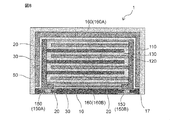
- FIG. 3A is a side sectional view schematically showing the configuration of the solid-state battery according to the embodiment of the present invention.
- FIG. 3B is a sectional view (planar sectional view) of IIIB-IIIB of FIG. 3A.
- FIG. 4 is a plan sectional view schematically showing the configuration of a solid-state battery according to another embodiment of the present invention.
- FIG. 5 is a plan sectional view schematically showing the configuration of a solid-state battery according to another embodiment of the present invention.
- FIG. 1 is a side sectional view schematically showing the internal structure of the solid-state battery laminate.
- FIG. 2 is a side sectional view schematically showing another internal configuration of the solid-state battery laminate.
- FIG. 3A is a side sectional view schematically showing the configuration of the solid-
- FIG. 6 is a side sectional view schematically showing the configuration of a solid-state battery according to another embodiment of the present invention.
- FIG. 7 is a side sectional view schematically showing the configuration of a solid-state battery according to another embodiment of the present invention.
- FIG. 8 is a side sectional view schematically showing the configuration of a solid-state battery according to another embodiment of the present invention.
- FIG. 9A is a side sectional view schematically showing the configuration of the solid-state battery according to another embodiment of the present invention (the IXA-IXA sectional view of FIG. 9B).
- 9B is a cross-sectional view taken along the line IXB-IXB of FIG. 9A.
- FIG. 10 is a process sectional view (side sectional view) showing a manufacturing flow of a solid-state battery according to an embodiment of the present invention.
- FIG. 11 is a process sectional view (side sectional view) showing a manufacturing flow of a solid-state battery according to another embodiment of the present invention.
- FIG. 12 is a process sectional view (side sectional view) showing a modified example of the manufacturing flow of the solid-state battery according to the embodiment of the present invention.
- the "packaged solid-state battery” in the present invention means a solid-state battery protected from the external environment in a broad sense, and in a narrow sense, prevents water vapor in the external environment from entering the inside of the solid-state battery. It refers to the solid-state battery that is used.
- the term "water vapor” as used herein refers to water vapor typified by water vapor in the atmosphere, and in a preferred embodiment means water vapor including not only water vapor having a gas form but also liquid water. There is.
- the liquid state water may include dew condensation water in which gaseous water is condensed.
- the solid-state battery of the present invention from which such moisture permeation is prevented is packaged for substrate mounting, and in particular for surface mounting. Therefore, in a preferred embodiment, the battery of the present invention is an SMD (SMD: Surface Mount Device) type battery.
- SMD Surface Mount Device
- the "solid-state battery” as used in the present invention refers to a battery whose components are solid-state in a broad sense, and to an all-solid-state battery whose components (particularly preferably all components) are solid-state in a narrow sense. ..
- the solid-state battery in the present invention is a laminated solid-state battery in which the layers forming the battery building unit are laminated to each other, and preferably such layers are made of a sintered body.
- the "solid-state battery” includes not only a so-called “secondary battery” that can be repeatedly charged and discharged, but also a "primary battery” that can only be discharged.
- a “solid-state battery” is a secondary battery.
- the "secondary battery” is not overly bound by its name and may include, for example, a power storage device.
- the "sintering” referred to in the present invention may be defined as long as the sintering is achieved at least in a part of the "sintering".
- the "side cross section” referred to in the present specification is a form when viewed from a direction substantially perpendicular to the thickness direction based on the stacking direction of each layer constituting the solid-state battery (in short, a surface parallel to the thickness direction). It is based on the form when cut out with.
- the "planar cross section” is a form when viewed from a direction substantially parallel to the thickness direction based on the stacking direction of each layer constituting the solid-state battery (in short, cut out on a plane perpendicular to the thickness direction). It is based on the form of the case).
- the "vertical direction” and “horizontal direction” used directly or indirectly in the present specification correspond to the vertical direction and the horizontal direction in the figure, respectively.
- the same sign or symbol shall indicate the same member / part or the same meaning.
- the vertical downward direction ie, the direction in which gravity acts
- the opposite direction corresponds to the "upward direction”.
- the “top surface” means a surface that is positioned relatively upward among the surfaces constituting the battery, and the “bottom surface” is a relative of the surfaces constituting the battery. It means the surface that is positioned on the lower side. Assuming a typical solid-state battery in which two opposing main surfaces exist, the “top surface” as used herein refers to one of the main surfaces, and the “bottom surface” refers to the main surface. Pointing to the other side of the face.
- the solid-state battery 1 comprises a solid-state battery laminate 100 (see FIGS. 1 and 2), and the solid-state battery laminate 100 includes a positive electrode layer 110, a negative electrode layer 120, and a solid electrolyte 130 at least interposed between them. It has a laminated portion 140 including a battery constituent unit composed of the same, and an external terminal 150 provided on a side surface of the laminated portion.
- the solid-state battery laminate 100 is supported by the support substrate 10 (see FIG. 3A). Further, the solid-state battery 1 may have a coated insulating film 30 that covers the solid-state battery laminate 100 and a coated inorganic film 50 that covers the coated insulating film 30.
- the positive electrode layer 110, the negative electrode layer 120, the solid electrolyte 130, and the like may form a sintered layer.
- the positive electrode layer, the negative electrode layer and the solid electrolyte are each integrally fired, and therefore the laminated portion may form an integrally sintered body.
- the direction in which the positive electrode layer and the negative electrode layer are laminated (vertical direction) is defined as the “stacking direction”, and the direction intersecting the stacking direction is the horizontal direction in which the positive electrode layer and the negative electrode layer extend.
- the positive electrode layer 110 is an electrode layer including at least a positive electrode active material.
- the positive electrode layer may further contain a solid electrolyte.
- the positive electrode layer is composed of a sintered body containing at least positive electrode active material particles and solid electrolyte particles.
- the negative electrode layer 120 is an electrode layer including at least a negative electrode active material.
- the negative electrode layer may further contain a solid electrolyte.
- the negative electrode layer is composed of a sintered body containing at least negative electrode active material particles and solid electrolyte particles.
- the film thickness of the positive electrode layer or the negative electrode layer may be 5 ⁇ m or more and 60 ⁇ m or less, preferably 8 ⁇ m or more and 50 ⁇ m or less. Further, it may be 5 ⁇ m or more and 30 ⁇ m or less.
- the positive electrode active material and the negative electrode active material are substances involved in the transfer of electrons in a solid-state battery. Ions move (conduct) between the positive electrode layer and the negative electrode layer via the solid electrolyte, and electrons are transferred to charge and discharge.
- the positive electrode layer and the negative electrode layer are particularly preferably layers capable of occluding and releasing lithium ions or sodium ions. That is, the solid-state battery is preferably an all-solid-state secondary battery in which lithium ions or sodium ions move between the positive electrode layer and the negative electrode layer via the solid electrolyte to charge and discharge the battery.
- Examples of the positive electrode active material contained in the positive electrode layer include a lithium-containing phosphoric acid compound having a pearcon-type structure, a lithium-containing phosphoric acid compound having an olivine-type structure, a lithium-containing layered oxide, and lithium having a spinel-type structure. At least one selected from the group consisting of oxides and the like can be mentioned.
- the lithium-containing phosphoric acid compound having a pear-con type structure Li 3 V 2 (PO 4 ) 3 and the like can be mentioned.
- Examples of the lithium-containing phosphoric acid compound having an olivine-type structure include Li 3 Fe 2 (PO 4 ) 3 , LiFePO 4 , LiMnPO 4, and the like.
- Examples of the lithium-containing layered oxide include LiCoO 2 , LiCo 1/3 Ni 1/3 Mn 1/3 O 2, and the like.
- Examples of the lithium-containing oxide having a spinel-type structure include LiMn 2 O 4 , LiNi 0.5 Mn 1.5 O 4, and the like.
- the type of the lithium compound is not particularly limited, and may be, for example, a lithium transition metal composite oxide and a lithium transition metal phosphoric acid compound.
- the lithium transition metal composite oxide is a general term for oxides containing lithium and one or more kinds of transition metal elements as constituent elements, and the lithium transition metal phosphoric acid compound is one or more kinds of lithium. It is a general term for phosphoric acid compounds containing the transition metal element of.
- the type of the transition metal element is not particularly limited, and is, for example, cobalt (Co), nickel (Ni), manganese (Mn), iron (Fe), and the like.
- the positive electrode active material capable of occluding and releasing sodium ions includes a sodium-containing phosphoric acid compound having a nacicon-type structure, a sodium-containing phosphoric acid compound having an olivine-type structure, a sodium-containing layered oxide, and sodium having a spinel-type structure. At least one selected from the group consisting of oxides and the like can be mentioned.
- sodium-containing phosphoric acid compounds Na 3 V 2 (PO 4 ) 3 , NaCoFe 2 (PO 4 ) 3 , Na 2 Ni 2 Fe (PO 4 ) 3 , Na 3 Fe 2 (PO 4 ) 3 , Na. 2 FeP 2 O 7 , Na 4 Fe 3 (PO 4 ) 2 (P 2 O 7 ), and at least one selected from the group consisting of NaFeO 2 as the sodium-containing layered oxide.
- the positive electrode active material may be, for example, an oxide, a disulfide, a chalcogenide, a conductive polymer, or the like.
- the oxide may be, for example, titanium oxide, vanadium oxide, manganese dioxide, or the like.
- the disulfide is, for example, titanium disulfide or molybdenum sulfide.
- the chalcogenide may be, for example, niobium selenate or the like.
- the conductive polymer may be, for example, disulfide, polypyrrole, polyaniline, polythiophene, polyparastyrene, polyacetylene, polyacene and the like.
- Examples of the negative electrode active material contained in the negative electrode layer include oxides containing at least one element selected from the group consisting of Ti, Si, Sn, Cr, Fe, Nb and Mo, carbon materials such as graphite, and graphite-lithium. At least one selected from the group consisting of compounds, lithium alloys, lithium-containing phosphoric acid compounds having a pearcon-type structure, lithium-containing phosphoric acid compounds having an olivine-type structure, lithium-containing oxides having a spinel-type structure, and the like. Be done. Examples of lithium alloys include Li-Al and the like.
- lithium-containing phosphoric acid compound having a pear-con type structure examples include Li 3 V 2 (PO 4 ) 3, LiTi 2 (PO 4 ) 3, and the like.
- lithium-containing phosphoric acid compound having an olivine-type structure examples include Li 3 Fe 2 (PO 4 ) 3 , LiCuPO 4, and the like.
- Li 4 Ti 5 O 12 and the like can be mentioned.
- the negative electrode active material capable of occluding and releasing sodium ions includes a sodium-containing phosphoric acid compound having a nacicon-type structure, a sodium-containing phosphoric acid compound having an olivine-type structure, a sodium-containing oxide having a spinel-type structure, and the like. There is at least one selected from the group consisting of.
- the positive electrode layer and / or the negative electrode layer may contain a conductive material.
- the conductive material contained in the positive electrode layer and the negative electrode layer include at least one metal material such as silver, palladium, gold, platinum, aluminum, copper and nickel, and carbon.
- the positive electrode layer and / or the negative electrode layer may contain a sintering aid.
- a sintering aid at least one selected from the group consisting of aluminum oxide, lithium oxide, sodium oxide, potassium oxide, boron oxide, silicon oxide, bismuth oxide and phosphorus oxide can be mentioned.
- the solid electrolyte 130 is a material capable of conducting lithium ions.
- the solid electrolyte 130 which forms a battery constituent unit in a solid-state battery, forms a layer in which lithium ions can be conducted between the positive electrode layer 110 and the negative electrode layer 120.
- Specific examples of the solid electrolyte include a lithium-containing phosphoric acid compound having a pearcon structure, an oxide having a perovskite structure, an oxide having a garnet type or a garnet type similar structure, and an oxide glass ceramics-based lithium ion conductor. Can be mentioned.
- Li 1.2 Al 0.2 Ti 1.8 (PO 4 ) 3 and the like can be mentioned.
- an oxide having a perovskite structure La 0.55 Li 0.35 TiO 3 and the like can be mentioned.
- oxides having a garnet-type or garnet-type similar structure include Li 7 La 3 Zr 2 O 12 and the like.
- oxide glass ceramics-based lithium ion conductor for example, a phosphoric acid compound (LATP) containing lithium, aluminum and titanium as a constituent element, and a phosphoric acid compound (LAGP) containing lithium, aluminum and germanium as constituent elements are used.
- LATP phosphoric acid compound
- LAGP phosphoric acid compound
- the solid electrolyte may be, for example, a glass electrolyte.
- the solid electrolyte layer may contain a sintering aid.
- the sintering aid contained in the solid electrolyte layer may be selected from, for example, the same materials as the sintering aid that can be contained in the positive electrode layer and the negative electrode layer.
- the positive electrode layer 110 and the negative electrode layer 120 may include a positive electrode current collector layer and a negative electrode current collector layer, respectively.
- the positive electrode current collector layer and the negative electrode current collector layer may each have the form of a foil, but from the viewpoint of reducing the manufacturing cost of the solid-state battery and reducing the internal resistance of the solid-state battery by integral firing, the form of the sintered body is adopted. You may have.
- the positive electrode current collector layer and the negative electrode current collector layer have the form of a sintered body, they may be composed of a sintered body containing a conductive material and a sintering aid.
- the conductive material contained in the positive electrode current collector layer and the negative electrode current collector layer may be selected from, for example, the same materials as the conductive materials that can be contained in the positive electrode layer and the negative electrode layer.
- the sintering aid contained in the positive electrode current collector layer and the negative electrode current collector layer may be selected from, for example, the same materials as the sintering aid that can be contained in the positive electrode layer and the negative electrode layer. It should be noted that the positive electrode collector layer and the negative electrode current collector layer are not essential in the solid-state battery, and a solid-state battery in which such a positive electrode current collector layer and the negative electrode current collector layer are not provided is also conceivable. That is, the solid-state battery in the present invention may be a solid-state battery without a current collector layer.
- a pair of external terminals 150 are provided on the side surface of the laminated portion 140 located in the direction intersecting the stacking direction.
- an external terminal may be provided from the side surface to the bottom surface of the laminated portion 140.
- an external terminal 150A on the positive electrode side connected to the positive electrode layer 110 and an external terminal 150B on the negative electrode side connected to the negative electrode layer 120 are provided, and the external terminal 150A on the positive electrode side is one. It may be formed on the side surface (left side in the illustrated example), and the external terminal 150B on the negative electrode side may be provided so as to face the external terminal 150A on the positive electrode side (right side in the illustrated example).
- a pair of external terminals 150 include a material having a high conductivity.
- the specific material of the external terminal is not particularly limited, but may include at least one selected from the group consisting of silver, gold, platinum, aluminum, copper, tin and nickel.
- An inactive substance portion 170 may be provided between the positive electrode layer 110 and the external terminal 150B on the negative electrode side and between the negative electrode layer 120 and the external terminal 150A on the positive electrode side (see FIG. 2).
- the inactive substance unit 170 is provided to insulate between the positive electrode layer 110 and the external terminal 150B on the negative electrode side, and between the negative electrode layer 120 and the external terminal 150A on the positive electrode side. That is, it is preferable that the non-active substance portion has at least electron insulating properties.
- a material conventionally used as an "inactive substance" of a solid-state battery may be used, or may be composed of a resin material, a glass material and / or a ceramic material or the like.
- the ceramic material includes at least one selected from the group consisting of aluminum oxide, boron nitride, silicon dioxide, silicon nitride, zirconium oxide, aluminum nitride, silicon carbide and barium titanate. be able to.
- the inactive substance portion may also be referred to as a "margin portion” or a "negative portion" because of its form.
- An insulating outermost layer 160 may be provided on the outermost side of the laminated portion 140.
- the insulating outermost layer 160 can generally be formed on the outermost side of the laminated portion 140 and is for electrically, physically and / or chemically protecting the solid-state battery laminate.
- the insulating outermost layer 160 includes an insulating outermost layer 160A on the top surface side and an insulating outermost layer 160B on the bottom surface side of the solid-state battery laminate 100.
- the material constituting the outermost layer of insulation is preferably excellent in insulation, durability and / or moisture resistance, and is environmentally safe, and includes, for example, a resin material, a glass material and / or a ceramic material. It may be there.
- the outermost insulating layer since the outermost insulating layer is manufactured by integral firing, it may have the form of a sintered body, and the sintered body containing a sintering aid that can be contained in the positive electrode layer and the negative electrode layer described above (for example, It may be composed of silicon oxide).
- the top surface and the bottom surface of the solid-state battery laminate may be the laminated portion 140 without providing the insulating outermost layer 160.
- the solid-state battery may be provided with a coated insulating film 30 provided so as to cover at least the solid-state battery laminate 100. As shown in FIGS. 3A and 3B, the solid-state battery laminate 100 provided on the support substrate 10 is largely wrapped by the coated insulating film 30 as a whole.
- the coated insulating film 30 preferably corresponds to a resin film. That is, it is preferable that the covering insulating film 30 contains a resin material. As can be seen from the embodiments shown in FIGS. 3A and 3B, this means that the solid-state battery laminate 100 provided on the support substrate 10 is sealed with the resin material of the coating insulating film 30.
- the coated insulating film 30 made of such a resin material, in combination with the coated inorganic film 50, preferably contributes to the reduction of moisture intrusion.
- the material of the covering insulating film may be any kind as long as it exhibits insulating properties.
- the resin may be either a thermosetting resin or a thermoplastic resin.
- examples of the specific resin material of the coating insulating film include epoxy-based resin, silicone-based resin, and / or liquid crystal polymer.
- the thickness of the coating insulating film may be 30 ⁇ m or more and 1000 ⁇ m or less, for example, 50 ⁇ m or more and 300 ⁇ m or less.
- the coated insulating film is not essential for the solid-state battery, and a solid-state battery without the coated insulating film can be considered.
- the solid-state battery may be provided with a coated inorganic film 50 that covers the coated insulating film 30. As shown in FIGS. 3A and 3B, since the coated inorganic film 50 is positioned on the coated insulating film, it has a form of largely enclosing the solid-state battery laminate on the support substrate together with the coated insulating film. ing.
- the coated inorganic film preferably has a thin film form.
- the material of the coated inorganic film is not particularly limited as long as it contributes to the inorganic film having a thin film form, and may be metal, glass, oxide ceramics, or a mixture thereof.
- the coated inorganic film comprises a metallic component. That is, the coated inorganic film is preferably a metal thin film.
- the thickness of such a coated inorganic film may be 0.1 ⁇ m or more and 100 ⁇ m or less, for example, 1 ⁇ m or more and 50 ⁇ m or less.
- the coated inorganic film 50 may be a dry plating film, particularly if it depends on the manufacturing method.
- a dry plating film is a film obtained by a vapor phase method such as physical vapor deposition (PVD) or chemical vapor deposition (CVD), and has a very small thickness on the order of nano or micron. is doing.
- PVD physical vapor deposition
- CVD chemical vapor deposition
- Such a thin dry plating film contributes to more compact packaging.
- the dry plating film is, for example, aluminum (Al), nickel (Ni), palladium (Pd), silver (Ag), tin (Sn), gold (Au), copper (Cu), titanium (Ti), platinum (Pt). ), Silicon / silicon (Si), at least one metal component / semi-metal component selected from the group consisting of SUS and the like, an inorganic oxide and / or a glass component and the like.
- a dry plating film composed of such components is chemically and / or thermally stable, resulting in a solid-state battery having excellent chemical resistance, weather resistance and / or heat resistance, and having further improved long-term reliability. Can be done.
- the coated inorganic film is not indispensable, and a solid-state battery in which the coated inorganic film is not provided is also conceivable.
- the support substrate 10 is a substrate provided so as to support the solid-state battery laminate 100.
- a support substrate is located on one side of the main surface of the solid-state battery for "support”. Further, since it is a "substrate", it preferably has a thin plate-like form as a whole.
- the support substrate may be, for example, a resin substrate or a ceramic substrate, and a substrate having water resistance is preferable.
- the support substrate is a ceramic substrate. That is, the support substrate contains ceramic, which occupies the base material component of the substrate.
- a support substrate made of ceramic is a preferable substrate in terms of heat resistance in substrate mounting as well as contributing to prevention of water vapor permeation.
- Such a ceramic substrate can be obtained by firing, for example, by firing a green sheet laminate.
- the ceramic substrate may be, for example, an LTCC substrate (LTCC: LowTemperature Co-firedCeramics) or an HTCC substrate (HTCC: HighTemperatureCo-firedCeramic).
- the thickness of the support substrate may be 20 ⁇ m or more and 1000 ⁇ m or less, for example, 100 ⁇ m or more and 300 ⁇ m or less.
- the support substrate also functions as a terminal substrate for the solid-state battery laminate. That is, a solid-state battery packaged in such a form that a substrate is interposed can be mounted on another secondary substrate such as a printed wiring board. For example, a solid-state battery can be surface-mounted via a support substrate through solder reflow or the like. From this, it can be said that the packaged solid-state battery is an SMD type battery.
- the terminal board is made of a ceramic board
- the solid-state battery can be an SMD type battery having high heat resistance and can be solder-mounted.
- the support substrate of a preferred embodiment is provided with wiring for electrically connecting the upper and lower surfaces of the substrate, and is a terminal substrate for the external terminal of the packaged solid-state battery.
- the wiring 17 on the terminal board is not particularly limited and may have any form as long as it contributes to the electrical connection between the upper surface and the lower surface of the board. Since it contributes to electrical connection, it can be said that the wiring 17 on the terminal board is a conductive portion of the board.
- the conductive portion of such a substrate may have a form such as a wiring layer, vias and / or lands.
- the support substrate 10 is provided with vias 14 and / or lands 16.
- the term "via” as used herein refers to a member for electrically connecting the vertical direction of the support substrate, that is, the thickness direction of the substrate, and for example, a filled via is preferable, and an inner via may be used. ..
- connection portion refers to a terminal portion / connection portion (preferably a terminal portion connected to a via) for electrical connection provided on the upper main surface and / or the lower main surface of the support substrate. -It points to a connection part), and may be, for example, a corner land or a round land.
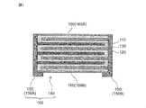
- the solid-state battery of the present invention further includes a moisture absorbing film 20 in addition to the basic configuration of the solid-state battery described above (see FIGS. 3A and 3B).
- the moisture absorbing film 20 absorbs moisture contained in the solid-state battery, is in contact with at least a part of the solid-state battery laminate 100, and is closely integrated with the solid-state battery laminate 100.
- "in contact with at least a part and closely integrated" in the present specification means a state in which they are in close contact with each other and integrated with each other without substantially having a gap.
- the moisture absorbing film 20 absorbs moisture with respect to at least one material selected from the group consisting of aluminum oxide, lithium oxide, sodium oxide, potassium oxide, boron oxide, silicon oxide, bismuth oxide and phosphorus oxide. It is composed of a material having a hygroscopic effect, and is formed into a film by kneading these materials with, for example, a binder resin. That is, in one preferred embodiment, the hygroscopic film contains a material having a hygroscopic effect and a binder resin.
- the material having a hygroscopic effect of absorbing moisture include at least one selected from the group consisting of synthetic zeolite, silica gel, phosphorus pentoxide, barium oxide, calcium oxide and an organic metal structure.
- the hygroscopic membrane containing synthetic zeolite is a material that has good temperature resistance and does not deliquesce even when the synthetic zeolite generates heat due to the operation of the solid-state battery and the temperature of the synthetic zeolite becomes high, and the adsorption rate per unit weight is high. It is suitable because it is good.
- the binder resin include an inorganic binder and / or a resin binder.
- the inorganic binder a glass binder can be mentioned. That is, the hygroscopic film may contain a material having a hygroscopic effect and a glass binder.
- the thickness of the moisture absorbing film may be 1 ⁇ m or more and 50 ⁇ m or less from the viewpoint of preventing the volume increase of the solid-state battery, and is preferably 5 ⁇ m or more and 30 ⁇ m or less or 5 ⁇ m or more and 15 ⁇ m or less. Further, the thickness of the hygroscopic film may be uniform or non-uniform. Further, although the moisture absorbing film shows the embodiment of the monolayer film in the embodiments of FIGS. 3A and 3B, the hygroscopic film may be a plurality of films having two or more layers.
- the content of synthetic zeolite or silica gel, which is a preferable material, in the hygroscopic membrane 20 is preferably 1% by volume or more and 85% by volume or less based on the entire hygroscopic membrane, which will be described later. It should be noted that the reference time in the overall hygroscopic film standard may be the time when the solid-state battery is completed.
- the moisture absorbing film 20 is covered so as to be in contact with a pair of external terminals 150 provided opposite to each other in the solid-state battery laminate and to be closely integrated with the external terminals on the side surface. 3A and 3B).
- the "side surface of the solid-state battery laminate" referred to in the present specification is, for example, the "top surface” defined above among the six surfaces constituting the battery having a substantially hexahedral shape in FIGS.
- the solid-state battery laminate is not limited to a substantially hexahedron shape, and may be, for example, a cylindrical shape. In the case of a cylindrical shape, the outer periphery is perpendicular to the “top surface” and the “bottom surface”. Cover the surface.
- the moisture absorbing film 20 and the external terminal 150 of the solid-state battery laminate 100 are closely integrated and have no gap, and the moisture absorbing film 20 absorbs moisture. Further, in the solid-state battery of the present invention, by covering the side surface located in the direction intersecting the stacking direction, which is a place where deterioration is likely to occur when moisture invades, with a moisture absorbing film, the moisture is effectively absorbed and the solid-state battery is laminated. It is possible to reduce the invasion of water into the inside of the body.
- the moisture absorbing film 20 is provided so as to extend from the side surface of the external terminal 150 to the top surface which is the outermost insulating layer surface of the laminated portion 140 in the side sectional view of the solid-state battery.
- the hygroscopic film has a form of bending in a side sectional view.
- the moisture absorbing film 20 covers the interface between the external terminal 150 and the laminated portion 140 in a side sectional view of the solid-state battery.
- the volume increase of the solid-state battery can be suppressed by setting the thickness of the moisture-absorbing film 20 in the solid-state battery to about 1 ⁇ m or more and 50 ⁇ m or less. Therefore, it is possible to suppress a decrease in the energy density per volume and to reduce the size of the package.
- FIG. 4 is a plan sectional view schematically showing the configuration of a solid-state battery according to another embodiment of the present invention.
- the moisture absorbing film 20 may be covered so as to be in close contact with and closely integrated with the side surface of the laminated portion 140 together with the external terminal 150. According to such an embodiment, since the moisture absorbing film is provided over the entire side surface of the solid-state battery laminate 100, it is possible to more effectively reduce the intrusion of moisture into the solid-state battery laminate.
- the moisture absorbing film is provided over the entire four side surfaces of the solid-state battery laminate.
- the inside of the solid-state battery laminate is provided. You may reduce the invading moisture.
- FIG. 5 is a plan sectional view schematically showing the configuration of a solid-state battery according to another embodiment of the present invention.
- the moisture absorbing film 20 may be coated so as to be in close contact with and closely integrated with the side surface of the laminated portion 140 of the solid-state battery laminate excluding the external terminal 150. Even in such an embodiment, since most of the side surfaces of the solid-state battery laminate are covered with the moisture-absorbing film 20, it is possible to reduce the intrusion of moisture into the solid-state battery laminate.
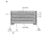
- FIG. 6 is a side sectional view schematically showing the configuration of a solid-state battery according to another embodiment of the present invention. Even if the moisture absorbing film 20 is covered so as to be in contact with the entire side surface of the solid-state battery laminate 100 as well as the insulating outermost layer surface (top surface and bottom surface) of the insulating outermost layer 160 of the solid-state battery laminate 100 so as to be closely integrated. good. More specifically, the entire surface of the solid-state battery laminate 100 is covered with the moisture absorbing film 20. According to such an embodiment, in addition to the intrusion of moisture from the side surface of the solid-state battery laminate 100, it is possible to suppress the unexpected intrusion of moisture from the stacking direction (vertical direction) of the solid-state battery laminate 100. ..
- FIG. 7 is a side sectional view schematically showing the configuration of a solid-state battery according to another embodiment of the present invention.
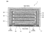
- the moisture absorbing film 20 may be coated so as to be in contact with and closely integrated with the insulating outermost layer surface (top surface and bottom surface) of the insulating outermost layer 160 of the laminated portion 140 in the solid-state battery laminate. That is, in this embodiment, the moisture absorbing film is not provided on the side surface of the solid-state battery laminate. Even with such an embodiment, it is possible to reduce the unexpected intrusion of moisture from the stacking direction (vertical direction).
- FIG. 8 is a side sectional view schematically showing the configuration of a solid-state battery according to another embodiment of the present invention.
- the moisture-absorbing film 20 is in close contact with the support surface of the support substrate 10 that supports the solid-state battery laminate 100 as well as the entire insulation outermost layer surface (top surface and bottom surface) and the side surface of the insulation outermost layer 160 of the solid-state battery laminate 100. It may be coated so as to be integrated. According to such an embodiment, in addition to the intrusion of moisture from the entire surface of the solid-state battery laminate 100, the moisture can be absorbed by the support surface of the support substrate before the moisture reaches the solid-state battery laminate 100. , The intrusion of water into the solid-state battery can be further reduced.
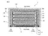
- FIG. 9A is a side sectional view schematically showing the configuration of the solid-state battery according to another embodiment of the present invention (IXA-IXA sectional view of FIG. 9B), and FIG. 9B is an IXB-IXB sectional view of FIG. 9A.
- the solid-state battery laminate may be supported by the support substrate so that the stacking direction of the laminated portion 140 and the support surface of the support substrate 10 are parallel to each other (see FIG. 9B).
- the present embodiment shows an embodiment in which the entire surface of the laminated portion 140 is covered with the moisture absorbing film 20 (see FIG.
- the moisture absorbing film may be provided so as to cover at least the interface between the laminated portion and the external terminal. good. According to such a configuration, the interface between the laminated portion and the external terminal is covered with a moisture absorbing film, and moisture is absorbed by the moisture absorbing film, so that the intrusion of moisture into the solid-state battery can be reduced. Further, according to this embodiment, even if expansion occurs in the stacking direction due to charging / discharging or the like, deformation of the support substrate due to expansion can be reduced.
- parallel as used herein is not limited to a state of being completely parallel, but also includes a state of being substantially parallel.
- the object of the present invention is obtained by preparing a solid-state battery containing a positive electrode layer, a negative electrode layer, and a battery building unit having a solid electrolyte between the electrodes, and then packaging the solid-state battery. be able to.
- the solid-state battery of the present invention is manufactured by manufacturing the laminated portion 140 (FIG. 10 (a)), forming the external terminal 150 (FIG. 10 (b)), and forming the moisture absorbing film 20 (FIG. 10 (a)). c)), fixing to the support substrate 10 (FIG. 10 (d)), and forming the coated insulating film 30 and the coated inorganic film 50 (FIG. 10 (e)).
- the explanation will be given step by step.
- the laminated portion 140 can be manufactured by a printing method such as a screen printing method, a green sheet method using a green sheet, or a composite method thereof. That is, the laminated portion itself may be manufactured according to a conventional solid-state battery manufacturing method (therefore, the solid electrolyte, the organic binder, the solvent, any additive, the positive electrode active material, the negative electrode active material, etc. described below, etc. As the raw material, those used in the manufacture of known solid-state batteries may be used).
- a slurry by mixing a solid electrolyte, an organic binder, a solvent and any additive. Then, a sheet having a thickness of about 10 ⁇ m after firing is obtained by sheet molding from the prepared slurry.
- a positive electrode active material, a solid electrolyte, a conductive material, an organic binder, a solvent and any additive are mixed to prepare a positive electrode paste.
- the negative electrode active material, the solid electrolyte, the conductive material, the organic binder, the solvent and any additive are mixed to prepare a paste for the negative electrode. Then, the positive electrode paste is printed on the sheet, and the current collector layer and / or the negative layer is printed as needed.
- the negative electrode paste is printed on the sheet, and the current collector layer and / or the negative layer is printed as needed. Then, the sheet on which the positive electrode paste is printed and the sheet on which the negative electrode paste is printed are alternately laminated to obtain a laminate.
- the outermost insulating layer (uppermost layer and / or lowest layer) of the laminated body it may be an electrolyte layer, an insulating layer, or an electrode layer.
- laminated portion 140 After crimping and integrating the laminate, cut it to the specified size. The obtained cut laminate is subjected to degreasing and firing. As a result, a sintered laminated body (laminated portion 140) is obtained. The laminate may be subjected to degreasing and firing before cutting, and then cut.
- the external terminal on the positive electrode side can be formed by applying a conductive paste to the exposed side surface of the positive electrode in the laminated portion 140.
- the external terminal on the negative electrode side can be formed by applying a conductive paste to the exposed side surface of the negative electrode in the laminated portion 140. If the external terminals on the positive electrode side and the negative electrode side are provided so as to extend to the lower surface of the sintered laminate, they can be connected to the mounting land in a small area in the next step (more specifically, the lower surface of the sintered laminate).
- the external terminal provided so as to extend to has a folded portion on the lower surface thereof, and such a folded portion can be electrically connected to the mounting land).
- the component of the external terminal may be selected from at least one selected from silver, gold, platinum, aluminum, copper, tin and nickel.
- the external terminals on the positive electrode side and the negative electrode side are not limited to being formed after sintering the laminated body, but may be formed before firing and subjected to simultaneous sintering.
- a moisture absorbing film 20 is formed on the solid-state battery laminate 100.
- at least one powder selected from the group consisting of synthetic zeolite, silica gel, phosphorus pentoxide, barium oxide, calcium oxide, and an organic metal structure is mixed with a binder resin together with a solvent to prepare a paste solution.
- a desired location where the moisture absorbing film is formed for example, the side surface where the external terminal of the solid-state battery laminate is formed, the side surface where the external terminal of the solid-state battery laminate is not formed, the insulating outermost layer of the solid-state battery laminate).
- a moisture absorbing film is formed by dipping the paste solution.
- the film thickness of the hygroscopic film is adjusted by the number of dips. Further, when the moisture absorbing film is formed on the entire surface of the solid-state battery laminate, the solid-state battery laminate may be completely dipped in the paste solution (see FIG. 11 (c)).
- the formation of the hygroscopic film and the subsequent steps are preferably performed in a dry atmosphere in order to prevent the hygroscopic film from absorbing moisture during the steps.
- a method of forming a hygroscopic film by dipping it in a paste solution has been described, but the method is not limited to this method, and for example, a paste solution may be spray-coated to form a hygroscopic film. good.
- a support board provided with vias and / or lands is used so that it can be surface-mounted on a secondary board. For example, it can be obtained by laminating and firing a plurality of green sheets. This is especially true when the support substrate is a ceramic substrate.
- the support substrate can be prepared, for example, according to the preparation of the LTCC substrate.
- a method of forming holes for example, a method of forming holes (diameter size: about 50 ⁇ m or more and 200 ⁇ m or less) by punch press or carbon dioxide laser, and filling the holes with a conductive paste material, or printing. Manufactured by a method using the method.
- the solid-state battery laminate 100 is arranged on the support substrate 10 so that the conductive portion of the support substrate 10 and the external terminal 150 of the solid-state battery laminate 100 are electrically connected to each other. .. Then, the conductive paste may be applied onto the support substrate 10 so that the conductive portion of the support substrate 10 and the external terminal 150 of the solid-state battery laminate 100 are electrically connected to each other.
- the conductive paste in addition to the Ag conductive paste, a conductive paste such as a nanopaste, an alloy paste or a brazing material, which does not require cleaning of flux or the like after formation, can be used.
- the coated insulating film 30 is formed so as to cover the solid-state battery laminate 100 on the support substrate 10. Therefore, the raw material of the coated insulating film 30 is provided so that the solid-state battery laminate 100 on the support substrate 10 is entirely covered.
- the coated insulating film 30 is made of a resin material, a resin precursor is provided on the support substrate 10 and subjected to curing or the like to form the coated insulating film 30.
- the coated insulating film 30 may be formed by applying pressure to the mold.
- the coated insulating film 30 that seals the solid-state battery laminate 100 on the support substrate 10 may be molded through a compression mold.
- the form of the raw material of the coating insulating film may be granular, or the type may be thermoplastic. It should be noted that such molding is not limited to mold molding, and may be performed through polishing, laser processing, and / or chemical processing.
- the coated insulating film 30 made of a resin material when the coated insulating film 30 made of a resin material is cured, the coated insulating film 30 shrinks, and the stress generated by the shrinkage may have some influence on the solid-state battery laminate 100.
- the moisture absorbing film 20 is formed on the solid-state battery laminate 100 before the covering insulating film 30 is formed. Therefore, even if a shrinkage stress occurs when the covering insulating film 30 is cured, the stress can be relaxed by the moisture absorbing film 20 and the influence on the solid-state battery laminate 100 can be reduced.
- the coated inorganic film 50 may be subjected to dry plating, for example, and a dry plated film may be used as the coated inorganic film. More specifically, dry plating is performed to form the coated inorganic film 50 on an exposed surface other than the bottom surface of the coated precursor (that is, other than the bottom surface of the support substrate). In one preferred embodiment, sputtering is performed to form a sputter film on an exposed outer surface other than the bottom surface of the coating precursor.
- the packaged solid-state battery according to the present invention can be finally obtained.
- the hygroscopic film may be formed after being fixed to the support substrate.
- a solid-state battery having a moisture-absorbing film 20 may be manufactured by dipping it in a paste solution in a state where the solid-state battery laminate 100 is fixed to the support substrate 10. According to such a manufacturing method, since the moisture absorbing film is formed on the support substrate together with the solid-state battery laminate, it is possible to more reliably reduce the intrusion of moisture into the solid-state battery.
- Example 1 -Solid-state battery Solid-state battery shown in FIGS. 3A and 3B-Hygroscopic material type: Synthetic zeolite (Tosoh Corporation Zeoram (registered trademark) A-5) -Volume fraction of hygroscopic material: 1% by weight based on the entire hygroscopic membrane
- Example 2 -Solid-state battery Solid-state battery shown in FIGS. 3A and 3B-Moisture-absorbing material type: Synthetic zeolite-Volume fraction of moisture-absorbing material: 20% by weight based on the entire moisture-absorbing film
- Example 3 -Solid-state battery Solid-state battery shown in FIGS. 3A and 3B-Moisture-absorbing material type: Synthetic zeolite-Volume fraction of moisture-absorbing material: 40% by weight based on the entire moisture-absorbing film
- Example 4 Solid-state battery shown in FIGS. 3A and 3B-Moisture-absorbing material type: Synthetic zeolite-Volume fraction of moisture-absorbing material: 80% by weight based on the entire moisture-absorbing film
- Example 5 Solid-state battery shown in Fig. 3A and Fig. 3B-Moisture-absorbing material type: Silica gel (Toyota Kako Co., Ltd. Toyota silica gel type A) -Volume fraction of hygroscopic material: 40% by weight based on the entire hygroscopic membrane
- Example 6 -Solid-state battery Solid-state battery shown in Fig. 4-Moisture-absorbing material type: Synthetic zeolite-Volume fraction of moisture-absorbing material: 40% by weight based on the entire moisture-absorbing film
- Example 7 Solid-state battery shown in Fig.
- 5-Moisture-absorbing material type Synthetic zeolite-Volume fraction of moisture-absorbing material: 40% by weight based on the entire moisture-absorbing film
- Example 8 -Solid-state battery Solid-state battery shown in Fig. 6-Moisture-absorbing material type: Synthetic zeolite-Volume fraction of moisture-absorbing material: 40% by weight based on the entire moisture-absorbing film
- Example 9 Solid-state battery shown in Fig. 7-Moisture-absorbing material type: Synthetic zeolite-Volume fraction of moisture-absorbing material: 40% by weight based on the entire moisture-absorbing film
- Example 10 -Solid-state battery Solid-state battery shown in Fig. 8-Moisture-absorbing material type: Synthetic zeolite-Volume fraction of moisture-absorbing material: 40% by weight based on the entire moisture-absorbing film
- Comparative example -Solid-state battery A solid-state battery that does not have a conventionally known moisture-absorbing film.
- the solid-state battery on which the coated inorganic film 50 was not formed was placed at 23 ° C. in an environment of 20% relative humidity (dew point of about 0 ° C.). It was stored for a week, and the rate of change between the change in discharge capacity after storage and the change in discharge capacity before storage was confirmed. For the calculation of the change in discharge capacity, a method of confirming the change in discharge capacity when the charge / discharge device was charged to 4.2 V and then discharged to 2.0 V was adopted. Further, in order to carry out the test in a state where moisture easily enters the solid-state battery, the above-mentioned verification test was performed on the solid-state battery not provided with the coated inorganic film. The verification test results are shown in Table 1 below.
- the rate of change in the discharge capacity of the solid-state batteries of Examples 1 to 10 was confirmed, it was better than the rate of change in the discharge capacity of the solid-state battery of the comparative example.
- the result was that the content was preferably 1% by volume or more and 85% by volume or less based on the entire moisture-absorbing film.
- the rate of change in the discharge capacity of the solid-state battery of Example 10 was small and very good. Since the moisture-absorbing film contains a resin binder or the like, the upper limit of the content of the moisture-absorbing material is set to 85% by volume, but if it can be formed as a film, the content of the resin binder or the like may be reduced. The content of the moisture absorbing material may be 85% by volume or more.
- the solid-state battery is not limited to a substantially hexahedral shape, and may be a polyhedral shape, a cylindrical shape, or a spherical shape.
- the packaged solid-state battery of the present invention can be used in various fields where battery use or storage is expected.
- the packaged solid-state battery of the present invention can be used in the field of electronics mounting.
- the fields of electricity, information, and communication in which mobile devices are used for example, mobile phones, smartphones, laptop computers and digital cameras, activity meters, arm computers, electronic paper, RFID tags, card-type electronic money, smart watches, etc.
- Electric / electronic equipment field including small electronic equipment or mobile equipment field
- home / small industrial use for example, electric tool, golf cart, home / nursing / industrial robot field
- large industrial use for example
- Forklifts, elevators, bay port cranes transportation systems (eg hybrid cars, electric cars, buses, trains, electrically assisted bicycles, electric motorcycles, etc.), power system applications (eg, various power generations, road conditioners) , Smart grid, general home-installed power storage system, etc.), as well as medical use (medical equipment field such as earphone hearing aid), pharmaceutical use (dose management system
- Solid-state battery 10 Support substrate 14 Via 16 Land 17 Wiring 20 Moisture-absorbing film 30 Coated insulating film 50 Coated inorganic film 100 Solid-state battery laminate 110 Positive electrode layer 120 Negative electrode layer 130 Solid electrolyte 140 Laminated part 150 External terminal 150A External terminal 150B on the positive electrode side External terminal on the negative electrode side 160 Insulation outermost layer 160A Insulation outermost layer top surface 160B Insulation outermost layer bottom surface 170 Inactive substance part
Landscapes
- Chemical & Material Sciences (AREA)
- Engineering & Computer Science (AREA)
- Chemical Kinetics & Catalysis (AREA)
- Electrochemistry (AREA)
- General Chemical & Material Sciences (AREA)
- Manufacturing & Machinery (AREA)
- Microelectronics & Electronic Packaging (AREA)
- Materials Engineering (AREA)
- Physics & Mathematics (AREA)
- Condensed Matter Physics & Semiconductors (AREA)
- General Physics & Mathematics (AREA)
- Inorganic Chemistry (AREA)
- Secondary Cells (AREA)
- Connection Of Batteries Or Terminals (AREA)
- Sealing Battery Cases Or Jackets (AREA)
- Cell Separators (AREA)
Priority Applications (3)
| Application Number | Priority Date | Filing Date | Title |
|---|---|---|---|
| JP2022533932A JP7626136B2 (ja) | 2020-07-01 | 2021-06-24 | 固体電池 |
| US18/147,464 US20230163365A1 (en) | 2020-07-01 | 2022-12-28 | Solid state battery |
| JP2024158474A JP2024175010A (ja) | 2020-07-01 | 2024-09-12 | 固体電池 |
Applications Claiming Priority (2)
| Application Number | Priority Date | Filing Date | Title |
|---|---|---|---|
| JP2020114378 | 2020-07-01 | ||
| JP2020-114378 | 2020-07-01 |
Related Child Applications (1)
| Application Number | Title | Priority Date | Filing Date |
|---|---|---|---|
| US18/147,464 Continuation US20230163365A1 (en) | 2020-07-01 | 2022-12-28 | Solid state battery |
Publications (1)
| Publication Number | Publication Date |
|---|---|
| WO2022004547A1 true WO2022004547A1 (ja) | 2022-01-06 |
Family
ID=79315314
Family Applications (1)
| Application Number | Title | Priority Date | Filing Date |
|---|---|---|---|
| PCT/JP2021/023937 Ceased WO2022004547A1 (ja) | 2020-07-01 | 2021-06-24 | 固体電池 |
Country Status (3)
| Country | Link |
|---|---|
| US (1) | US20230163365A1 (https=) |
| JP (2) | JP7626136B2 (https=) |
| WO (1) | WO2022004547A1 (https=) |
Cited By (2)
| Publication number | Priority date | Publication date | Assignee | Title |
|---|---|---|---|---|
| JPWO2022230901A1 (https=) * | 2021-04-26 | 2022-11-03 | ||
| WO2023026629A1 (ja) * | 2021-08-27 | 2023-03-02 | パナソニックIpマネジメント株式会社 | 電池 |
Citations (7)
| Publication number | Priority date | Publication date | Assignee | Title |
|---|---|---|---|---|
| JP2005056672A (ja) * | 2003-08-04 | 2005-03-03 | Nissan Motor Co Ltd | リチウム二次電池 |
| JP2010519675A (ja) * | 2006-09-20 | 2010-06-03 | オーク・リツジ・マイクロ−エナジー | 薄膜電池密閉パッケージ |
| JP2015111532A (ja) * | 2013-12-06 | 2015-06-18 | 株式会社オハラ | 全固体電池 |
| JP2015220102A (ja) * | 2014-05-19 | 2015-12-07 | Tdk株式会社 | 電池実装基板 |
| JP2017523575A (ja) * | 2014-08-13 | 2017-08-17 | ヴェリリー ライフ サイエンシズ エルエルシー | 封止型固体電池 |
| WO2018181288A1 (ja) * | 2017-03-28 | 2018-10-04 | Tdk株式会社 | 全固体リチウムイオン二次電池及び実装体 |
| WO2020203879A1 (ja) * | 2019-03-29 | 2020-10-08 | 株式会社村田製作所 | 固体電池 |
Family Cites Families (6)
| Publication number | Priority date | Publication date | Assignee | Title |
|---|---|---|---|---|
| JP2005116322A (ja) | 2003-10-07 | 2005-04-28 | Sumitomo Electric Ind Ltd | 非水電解質電池用包装材料及び非水電解質電池 |
| JP6646352B2 (ja) * | 2014-08-29 | 2020-02-14 | 住友化学株式会社 | 有機エレクトロルミネッセンス素子 |
| CN109937506A (zh) | 2016-11-15 | 2019-06-25 | 株式会社村田制作所 | 锂离子传导体、全固体电池、电子设备、电子卡、可穿戴设备以及电动车辆 |
| JP7199033B2 (ja) * | 2017-09-25 | 2023-01-05 | パナソニックIpマネジメント株式会社 | 電池 |
| US20210020880A1 (en) * | 2018-03-28 | 2021-01-21 | Honda Motor Co., Ltd. | Solid-state battery module |
| CN112567562B (zh) * | 2018-08-10 | 2023-12-05 | 株式会社村田制作所 | 固态电池 |
-
2021
- 2021-06-24 JP JP2022533932A patent/JP7626136B2/ja active Active
- 2021-06-24 WO PCT/JP2021/023937 patent/WO2022004547A1/ja not_active Ceased
-
2022
- 2022-12-28 US US18/147,464 patent/US20230163365A1/en active Pending
-
2024
- 2024-09-12 JP JP2024158474A patent/JP2024175010A/ja active Pending
Patent Citations (7)
| Publication number | Priority date | Publication date | Assignee | Title |
|---|---|---|---|---|
| JP2005056672A (ja) * | 2003-08-04 | 2005-03-03 | Nissan Motor Co Ltd | リチウム二次電池 |
| JP2010519675A (ja) * | 2006-09-20 | 2010-06-03 | オーク・リツジ・マイクロ−エナジー | 薄膜電池密閉パッケージ |
| JP2015111532A (ja) * | 2013-12-06 | 2015-06-18 | 株式会社オハラ | 全固体電池 |
| JP2015220102A (ja) * | 2014-05-19 | 2015-12-07 | Tdk株式会社 | 電池実装基板 |
| JP2017523575A (ja) * | 2014-08-13 | 2017-08-17 | ヴェリリー ライフ サイエンシズ エルエルシー | 封止型固体電池 |
| WO2018181288A1 (ja) * | 2017-03-28 | 2018-10-04 | Tdk株式会社 | 全固体リチウムイオン二次電池及び実装体 |
| WO2020203879A1 (ja) * | 2019-03-29 | 2020-10-08 | 株式会社村田製作所 | 固体電池 |
Cited By (3)
| Publication number | Priority date | Publication date | Assignee | Title |
|---|---|---|---|---|
| JPWO2022230901A1 (https=) * | 2021-04-26 | 2022-11-03 | ||
| JP7639898B2 (ja) | 2021-04-26 | 2025-03-05 | 株式会社村田製作所 | 固体電池パッケージ |
| WO2023026629A1 (ja) * | 2021-08-27 | 2023-03-02 | パナソニックIpマネジメント株式会社 | 電池 |
Also Published As
| Publication number | Publication date |
|---|---|
| US20230163365A1 (en) | 2023-05-25 |
| JPWO2022004547A1 (https=) | 2022-01-06 |
| JP2024175010A (ja) | 2024-12-17 |
| JP7626136B2 (ja) | 2025-02-04 |
Similar Documents
| Publication | Publication Date | Title |
|---|---|---|
| JP7192866B2 (ja) | 固体電池 | |
| JP5804053B2 (ja) | 固体電池 | |
| JP2024175010A (ja) | 固体電池 | |
| US12368184B2 (en) | Solid state battery | |
| JP7259980B2 (ja) | 固体電池 | |
| JP2020115450A (ja) | 全固体電池 | |
| JP7800329B2 (ja) | 固体電池パッケージ | |
| WO2020203877A1 (ja) | 固体電池 | |
| JP2025134830A (ja) | 固体電池 | |
| WO2021235451A1 (ja) | 固体電池および固体電池用の外装体 | |
| WO2021117827A1 (ja) | 固体電池 | |
| JP2024025996A (ja) | 固体電池および電池パッケージ | |
| JP7823749B2 (ja) | 固体電池および電子デバイス | |
| JP7131298B2 (ja) | 電子部品 | |
| JP7823732B2 (ja) | 固体電池および電子デバイス | |
| US20220302498A1 (en) | Solid-state battery | |
| JP2023180885A (ja) | 固体電池パッケージ | |
| US20250149689A1 (en) | Packaged solid-state battery | |
| WO2024009963A1 (ja) | 固体電池 | |
| WO2023243489A1 (ja) | 固体電池パッケージ | |
| WO2025204301A1 (ja) | 固体電池パッケージおよびその製造方法 | |
| WO2022114140A1 (ja) | 固体電池および固体電池の製造方法 | |
| JP2024025995A (ja) | 固体電池および電池パッケージ | |
| WO2026009697A1 (ja) | 固体電池、固体電池を備える固体電池パッケージおよび固体電池の製造方法 | |
| JP2023143252A (ja) | 固体電池パッケージ |
Legal Events
| Date | Code | Title | Description |
|---|---|---|---|
| 121 | Ep: the epo has been informed by wipo that ep was designated in this application |
Ref document number: 21832787 Country of ref document: EP Kind code of ref document: A1 |
|
| ENP | Entry into the national phase |
Ref document number: 2022533932 Country of ref document: JP Kind code of ref document: A |
|
| NENP | Non-entry into the national phase |
Ref country code: DE |
|
| 122 | Ep: pct application non-entry in european phase |
Ref document number: 21832787 Country of ref document: EP Kind code of ref document: A1 |