WO2021250748A1 - スライダー - Google Patents
スライダー Download PDFInfo
- Publication number
- WO2021250748A1 WO2021250748A1 PCT/JP2020/022560 JP2020022560W WO2021250748A1 WO 2021250748 A1 WO2021250748 A1 WO 2021250748A1 JP 2020022560 W JP2020022560 W JP 2020022560W WO 2021250748 A1 WO2021250748 A1 WO 2021250748A1
- Authority
- WO
- WIPO (PCT)
- Prior art keywords
- cover body
- slider
- side wall
- mounting column
- portions
- Prior art date
- Legal status (The legal status is an assumption and is not a legal conclusion. Google has not performed a legal analysis and makes no representation as to the accuracy of the status listed.)
- Ceased
Links
Images


Classifications
-
- A—HUMAN NECESSITIES
- A44—HABERDASHERY; JEWELLERY
- A44B—BUTTONS, PINS, BUCKLES, SLIDE FASTENERS, OR THE LIKE
- A44B19/00—Slide fasteners
- A44B19/24—Details
- A44B19/26—Sliders
- A44B19/262—Pull members; Ornamental attachments for sliders
-
- A—HUMAN NECESSITIES
- A44—HABERDASHERY; JEWELLERY
- A44B—BUTTONS, PINS, BUCKLES, SLIDE FASTENERS, OR THE LIKE
- A44B19/00—Slide fasteners
- A44B19/24—Details
- A44B19/26—Sliders
-
- A—HUMAN NECESSITIES
- A44—HABERDASHERY; JEWELLERY
- A44B—BUTTONS, PINS, BUCKLES, SLIDE FASTENERS, OR THE LIKE
- A44B19/00—Slide fasteners
- A44B19/24—Details
- A44B19/26—Sliders
- A44B19/30—Sliders with means for locking in position
- A44B19/308—Sliders with means for locking in position in the form of a spring-actuated locking member actuated by the pull member
Definitions
- the present invention relates to a slider used for a slide fastener.
- Patent Document 1 discloses a slider provided with an automatic stop mechanism.
- the slider 100 described in Patent Document 1 is formed by using a slider body 101, a pull tab 102, a spring member 103, and a cover body 104.
- the slider 100 is assembled by mounting the puller 102 and the spring member 103 on the slider body 101 and then attaching the cover body 104 to the front and rear mounting columns 101a of the slider body 101 by utilizing the elastic deformation of the cover body 104. Be done.
- the slider 100 that is assembled by utilizing the elastic deformation of the cover body 104 in this way can easily perform the assembly work of the slider 100, and is sometimes called a snap-in type slider.
- the cover body may receive a force from a puller and be pulled in the slider width direction. Therefore, even if the cover body receives such a force in the width direction, the cover body tilts in the width direction. It must be mounted on the slider fuselage so that it does not come off the front and rear mounting columns of the slider fuselage.
- the cover body 104 attached to the slider body 101 since the cover body 104 attached to the slider body 101 is in contact with the front and rear mounting columns 101a from the inside in the width direction, it receives the force in the width direction as described above. However, it is difficult to tilt in the width direction, and it is possible to prevent the cover body 104 from coming off the slider body 101. However, in order to use the slide fastener more stably for various products, it is required to more effectively prevent the cover body from tilting in the width direction.
- the present invention has been made in view of the above-mentioned conventional problems, and an object thereof is to make it difficult for the cover body to tilt in the width direction even if the cover body receives a force in the slider width direction. To provide a slider.
- the slider provided by the present invention includes a slider fuselage in which an element guide path is formed between an upper wing plate and a lower wing plate, a puller provided with a mounting shaft portion, and an elastically deformable cover.
- the element guide path communicates with the left and right shoulder openings provided at the front end portion in the length direction of the slider body and the rear opening provided at the rear end portion in the length direction, and has the body.
- the front mounting column and the rear mounting column of the slider are a pair of left and right first side wall portions and a pair of left and right second side wall portions arranged outside the first side wall portion in the length direction, respectively.
- the outer wall surface of the left and right second side wall portions has a portion, and is arranged inside in the width direction with respect to the outer wall surface of the left and right first side wall portions via a step portion, and the left and right first side wall portions.
- the portion is exposed to the outside, at least a part of the left and right second side wall portions is housed in the cover body, and at least a part of the outer wall surface of the second side wall portion faces the inner wall surface of the cover body. It is characterized by doing.
- the cover body includes a cover body portion arranged along the length direction, a front leg portion that bends and extends from the front end portion of the cover body portion toward the slider body portion, and the cover body portion. It has a rear leg portion that bends and extends from the rear end portion of the portion toward the slider body, and the front leg portion and the rear leg portion of the cover body are the front side mounting column and the rear side mounting of the slider body.
- the cover body which is engaged with each of the columns, has a cover main body portion extending from the front leg portion to the rear leg portion via the cover body portion, and at least the front leg portion and the rear leg portion are It is preferable to have left and right side surface portions extending from the left and right side edges of the cover main body portion toward the inner peripheral side of the cover main body portion.
- the cover body portion has left and right side surface portions extending from the left and right side edges of the cover body portion toward the inner peripheral side of the cover body portion, and the cover body portion is viewed from the side of the slider. It is preferable that the lower end portion of the side surface portion arranged on the front facing the upper end portion of the first side wall portion of the front side mounting column and the rear side mounting column. Further, the left and right side surface portions of the cover body are formed on a curved portion that bends from the cover body portion to the front leg portion or the rear leg portion when the cross section orthogonal to the width direction of the cover body is viewed. It is preferable to have a deformation allowable portion in which the distance between the main body portion and the inner peripheral side edge of the side surface portion is the shortest.
- the front mounting column and the rear mounting column each have an engaging claw portion for engaging the cover body, and the engaging claw portion is longer than the second side wall portion.
- the cover body Protruding outward in the direction, the cover body has front and rear accommodating holes for accommodating the engaging claw portion, and the front and rear accommodating holes penetrate the cover body along the length direction. Is preferable.
- the engaging claw portion of the front mounting column and the rear mounting column has a claw lower surface that contacts the cover body, and the claw lower surface has a cross section orthogonal to the width direction of the engaging claw portion. It has a curved surface that curves like an arc when viewed.
- the slider body may have a front concave groove portion provided toward the front from the front mounting pillar and a rear concave groove portion provided toward the rear from the rear mounting pillar. preferable.
- the slider according to the present invention even if the cover body receives a force in the width direction of the slider, it is possible to make it more difficult for the cover body to tilt in the width direction.
- FIG. 5 is an exploded perspective view schematically showing a state in which the slider according to the first embodiment of the present invention is disassembled. It is a side view of the main part schematically showing the main part of the slider which concerns on Example 1.
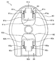
- FIG. It is sectional drawing which shows typically the cross section orthogonal to the width direction of the slider which concerns on Example 1.
- FIG. It is sectional drawing which shows typically the cross section orthogonal to the width direction in the slider body of the slider which concerns on Example 1.
- FIG. It is sectional drawing which shows typically the cross section orthogonal to the width direction in the cover body of the slider which concerns on Example 1.
- FIG. is a top view which shows typically the slider body of the slider which concerns on Example 2.
- FIG. is a side view of the slider body which concerns on Example 2.
- FIG. It is an exploded perspective view which shows the state which the conventional slider was dis
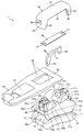
- FIG. 1 is an exploded perspective view showing a state in which the slider according to the first embodiment is disassembled.
- 2 and 3 are a side view of the slider according to the first embodiment and a cross-sectional view orthogonal to the width direction.
- the front-back direction means the length direction or the sliding direction of the slider.
- the direction in which the slider moves to engage the left and right element rows is the front (shoulder mouth side direction), and the direction in which the slider moves to separate the element rows (rear mouth side direction). Is the rear.
- the vertical direction means the height direction of the slider, for example, the direction orthogonal to the flat upper surface of the upper wing plate in the slider fuselage.
- the side to which the cover body (or the pull tab) is attached is upward with respect to the slider body of the slider, and the direction opposite to the cover body (or pull tab) is downward.
- the left-right direction refers to the width direction of the slider, and is a direction orthogonal to the length direction and the height direction of the slider.
- the slider 1 for a slide fastener is formed of five parts: a slider body 10, a pull tab 40, a stop claw body 50, a leaf spring member 60, and a cover body 30.
- the slider 1 is provided with an automatic stop mechanism by a stop claw body 50.
- the slider body 10, the pull tab 40, the stop claw body 50, and the cover body 30 are made of a synthetic resin having thermoplasticity.
- the leaf spring member 60 is made of metal.
- the material of the slider is not particularly limited and can be changed.
- at least some parts of the slider body, the pull tab, the stop claw body, and the cover body may be made of metal.
- the slider fuselage 10 includes an upper wing plate 20, a lower wing plate 11 arranged in parallel with the upper wing plate 20, a front end portion (shoulder opening side end portion) of the upper wing plate 20, and a front end portion (shoulder opening) of the lower wing plate 11.
- the connecting pillar 12 connecting the side end portions), the left and right upper flange portions 13 provided on the left and right side portions of the upper wing plate 20, and the left and right lower flange portions 14 provided on the left and right side portions of the lower wing plate 11.
- the slider body 10 includes a front mounting column (first mounting column) 21 and a rear mounting column (second mounting column) 22 that rise upward from the upper wing plate 20, and a front concave groove portion 23 provided in front of the front mounting column 21. And a rear concave groove portion 24 provided behind the rear mounting column 22.
- the front mounting column 21 and the rear mounting column 22 are arranged apart from each other in the front-rear direction, and the mounting shaft of the pull tab 40, which will be described later, is located between the front mounting column 21 and the rear mounting column 22. A gap into which the portion 43 can be inserted is provided.
- left and right shoulder openings are formed with the connecting pillar 12 in between.
- a rear opening is formed at the rear end of the slider body 10.
- a substantially Y-shaped element guide path 15 that communicates the left and right shoulder openings and the rear openings is formed between the upper wing plate 20 and the lower wing plate 11 of the slider fuselage 10.
- the left and right side edges of the slider body 10 are provided with a tape insertion gap for inserting a fastener tape of a slide fastener (not shown).
- the left and right tape insertion gaps in the slider body 10 are formed between the left and right upper flange portions 13 and the left and right lower flange portions 14.
- the front mounting column 21 of the first embodiment is more than the front base portion 21a arranged in the central portion in the width direction of the upper wing plate 20, the pair of left and right front side first side wall portions 21b, and the front side first side wall portion 21b.
- the left and right front first side wall portions 21b of the front mounting pillar 21 are provided integrally with the front base portion 21a on both the left and right sides of the front base portion 21a.
- Each of the left and right front side first side wall portions 21b has an outer wall surface arranged orthogonally to the width direction of the slider 1, and the left and right outer wall surfaces are formed on a flat flat surface.
- the outer wall surface of the front first side wall portion 21b is not housed in the cover body 30 attached to the slider body 10, but is exposed to the outside.
- the outer wall surface of the front first side wall portion 21b forms the same plane or substantially the same plane with respect to the outer surface of the front leg portion 32 described later of the cover body 30 attached to the slider body 10.
- the slider 1 is arranged in parallel with the outer surface of the front leg portion 32 of the cover body 30 at the same position or substantially the same position with respect to the width direction.
- the upper end portion (top end portion) of the left and right front first side wall portions 21b has an upper end surface (top end surface) arranged in parallel with the upper surface of the upper blade plate 20.
- the upper end surface of the front first side wall portion 21b faces the lower end portions of the left and right side surface portions 35 of the cover body portion 31 described later of the cover body 30.
- the upper end surface of the front first side wall portion 21b is in contact with the lower end portions of the left and right side surface portions 35 of the cover body portion 31, thereby supporting the cover main body portion 34 from below. There is.
- the left and right front second side wall portions 21c of the front mounting pillar 21 are housed in the cover body 30 attached to the slider body 10.
- at least a part of the front second side wall portion 21c is housed in the front leg portion 32 of the cover body 30 and is covered so as not to be seen from the outside.
- the left and right front side second side wall portions 21c extend forward from the front side first side wall portion 21b via the step portion 21g.
- the left and right front second side wall portions 21c project forward from the front end surface of the front base portion 21a. Further, the front second side wall portion 21c has a front end edge along the vertical direction. This facilitates contact of a part of the cover body 30 (cover body portion 34 of the front leg portion 32) with the left and right front second side wall portions 21c, and stabilizes the position of the cover body 30 with respect to the slider body 10 in the front-rear direction. be able to. Further, it is possible to prevent the cover body 30 from rattling in the front-rear direction.
- the outer wall surface of the left and right front second side wall portions 21c is formed as a flat surface orthogonal to the width direction.
- the outer wall surface of the left and right front second side wall portions 21c may be arranged so as to be inclined with respect to the length direction of the slider 1.
- the outer wall surface of the front side second side wall portion 21c is arranged inside the outer wall surface of the front side first side wall portion 21b in the width direction, and is arranged outside the outer wall surface of the front side first side wall portion 21b and the front side second side wall portion 21c.
- the above-mentioned step portion 21g is provided between the wall surface and the wall surface.
- the distance between the outer wall surfaces of the left and right front side second side wall portions 21c is smaller than the distance between the outer wall surfaces of the left and right front side first side wall portions 21b.
- the stepped portion 21g of the front mounting column 21 is inclined downward toward the front in the side view of the slider body 10.
- the outer wall surface of the front side second side wall portion 21c can be stably arranged inside the outer wall surface of the front side first side wall portion 21b in the width direction.
- the front leg portion 32 of the cover body 30 can be brought into sliding contact with the stepped portion 21g of the front mounting column 21 to guide the cover body 30 toward a predetermined position.
- the front leg portion 32 of the cover body 30 can be easily and smoothly engaged with the front engaging claw portion 21d of the front mounting column 21. Therefore, the workability of the assembly work of the slider 1 can be improved.
- the stepped portion 21g of the front mounting column 21 can absorb the thickness (dimension in the width direction) of the side surface portion 35 described later of the front leg portion 32 of the cover body 30, thereby, as described above, the front first side wall.
- the outer wall surface of the portion 21b and the outer surface of the front leg portion 32 of the cover body 30 can be arranged on the same plane without a step or on substantially the same plane with an extremely small step. As a result, the appearance of the slider 1 can be improved and the appearance quality thereof can be improved. In addition, it is possible to improve the feel of the slider 1 and prevent the slider 1 from being caught by a finger or another member.
- the flat outer wall surface of the left and right front second side wall portions 21c has a portion facing the left and right inner wall surfaces of the front leg portion 32 of the cover body 30.
- the outer wall surfaces of the left and right front second side wall portions 21c are arranged in contact with or close to the left and right inner wall surfaces of the front leg portions 32 of the cover body 30 from the inside. Further, by arranging the front side second side wall portion 21c inside the front leg portion 32 of the cover body 30 in this way, the outer wall surface of the front side second side wall portion 21c is viewed from the side view of the slider 1 (see FIG. 2).
- the area (area) where the inner wall surface of the cover body 30 and the inner wall surface of the cover body 30 contact or overlap each other (area) is larger than the area where the slider body 101 and the cover body 104 of the slider 100 described in Patent Document 1 come into contact with each other. Widely secured. As a result, as will be described later, it is possible to make it difficult for the cover body 30 to tilt in the width direction and increase the attachment strength of the cover body 30 to the slider body 10.
- the front engaging claw portion 21d of the front mounting column 21 is arranged between the left and right front second side wall portions 21c in the width direction, and is more than the left and right front side second side wall portions 21c, for example, as shown in FIG. It protrudes forward.
- the front engaging claw portion 21d is inclined downward from the upper surface of the claw and the upper surface of the claw toward the tip of the front engaging claw portion 21d when the cross section orthogonal to the width direction of the front engaging claw portion 21d is viewed. It has a surface and a claw lower surface 21h arranged from the tip end portion of the front side engaging claw portion 21d to the front end surface of the front side base portion 21a. Further, the claw lower surface 21h of the front engaging claw portion 21d has a concave curved surface curved in an arc shape in a cross section orthogonal to the width direction.
- a part of the cover body 30 (specifically, the cover main body portion 34 of the front leg portion 32) is a front engaging claw portion.
- the claw lower surface 21h of the front engaging claw portion 21d receives a load (stress) from the cover body 30.
- the load applied from the cover body 30 to the front engaging claw portion 21d can be easily dispersed, and a part of the front engaging claw portion 21d. It is possible to make it difficult to concentrate the load on. As a result, it is possible to prevent damage to the front engaging claw portion 21d and the front base portion 21a.
- the front protruding portion 21e of the front mounting column 21 protrudes upward from the front base portion 21a at a position between the front engaging claw portion 21d and the claw accommodating recess 21f in the front-rear direction.
- the front protruding portion 21e is inserted into a mounting hole portion 61 provided in the leaf spring member 60, which will be described later, whereby the position of the front end portion of the leaf spring member 60 with respect to the slider body 10 is determined.
- the claw accommodating recess 21f of the front mounting column 21 is formed downward from the upper surface of the front base portion 21a. At the lower end of the claw accommodating recess 21f, a bottom surface portion for supporting the support shaft portion 52 described later of the stop claw body 50 is formed. Further, the claw accommodating recess 21f is arranged at a position sandwiched between the left and right front side first side wall portions 21b.
- the rear mounting column 22 of the first embodiment has a rear base portion 22a arranged in the central portion in the width direction of the upper blade plate 20, a pair of left and right rear first side wall portions 22b, and a rear side first side wall portion.
- the rear base portion 22a is provided with a claw hole 22f that penetrates the rear mounting column 22 and the upper blade plate 20 in the vertical direction and communicates with the element guide path 15.
- the rear side first side wall portion 22b, the rear side second side wall portion 22c, the rear side engaging claw portion 22d, and the rear side projecting portion 22e in the rear side mounting column 22 of the first embodiment correspond to each other in the front side mounting column 21.
- Each of the corresponding front mounting columns 21 is formed with the front side first side wall portion 21b, the front side second side wall portion 21c, the front side engaging claw portion 21d, and the front side projecting portion 21e opposite to each other in the front-rear direction. It is formed substantially in the same way as the part.
- the rear side first side wall portion 22b, the rear side second side wall portion 22c, the rear side engaging claw portion 22d, and the rear side protruding portion 22e will be briefly described.
- the left and right rear first side wall portions 22b are provided integrally with the rear side base portion 22a, and have a flat outer wall surface arranged orthogonally to the width direction of the slider 1.
- the outer wall surface of the rear first side wall portion 22b is exposed to the outside. Further, the outer wall surface of the rear first side wall portion 22b is parallel to or substantially the same position as the outer surface of the rear leg portion 33 described later of the cover body 30 attached to the slider body 10 in the width direction of the slider 1.
- the outer wall surface of the rear first side wall portion 22b and the outer surface of the rear leg portion 33 of the cover body 30 are arranged on the same plane or substantially the same plane.
- the upper end portion (top end portion) of the left and right rear first side wall portions 22b has an upper end surface (top end surface) arranged in parallel with the upper surface of the upper blade plate 20.
- the upper end surface of the rear first side wall portion 22b faces the lower end portions of the left and right side surface portions 35 of the cover body portion 31 in the cover body 30, and particularly in the case of the first embodiment, the left and right side surface portions of the cover body portion 31. It is in contact with the lower end of 35.
- the left and right rear second side wall portions 22c are housed in the cover body 30 attached to the slider body 10.
- at least a part of the rear second side wall portion 22c is housed in the rear leg portion 33 of the cover body 30 and is covered so as not to be seen from the outside.
- the left and right rear second side wall portions 22c extend from the rear side first side wall portion 22b via the step portion 22g, and project rearward from the rear end surface of the rear side base portion 22a.
- the rear end edge of the rear second side wall portion 22c is along the vertical direction.
- the left and right rear second side wall portions 22c together with the left and right front side second side wall portions 21c, stabilize the position of the cover body 30 with respect to the slider body 10 in the front-rear direction, and the cover body 30 rattles in the front-rear direction. Can be suppressed.
- the outer wall surface of the left and right rear second side wall portions 22c is formed as a flat surface orthogonal to the width direction.
- the outer wall surface of the rear second side wall portion 22c may be arranged so as to be inclined with respect to the length direction of the slider 1.
- the outer wall surface of the rear second side wall portion 22c is arranged inside the outer wall surface of the rear side first side wall portion 22b in the width direction. Further, the step portion 22g is inclined downward toward the rear in the side view of the slider body 10.
- the rear leg portion 33 of the cover body 30 can be guided by the step portion 22g, so that the cover can be covered.
- the rear leg 33 of the body 30 can be easily and smoothly engaged with the rear engaging claw 22d of the rear mounting column 22.
- the step portion 22g can absorb the thickness of the side surface portion 35 in the rear leg portion 33 of the cover body 30, whereby the outer wall surface of the rear first side wall portion 22b and the outer surface of the rear leg portion 33 of the cover body 30 can be absorbed. Is arranged on the same plane or substantially the same plane, so that the appearance quality of the slider 1 can be improved.
- the outer wall surface of the left and right rear second side wall portions 22c has a portion facing the inner wall surface of the rear leg portion 33 of the cover body 30.
- the outer wall surface of the left and right rear second side wall portions 22c is arranged in contact with or close to the inner wall surface of the rear leg portion 33 of the cover body 30, and is arranged in contact with or close to the inner wall surface of the rear leg portion 33.
- a wide range of contact or overlap between the outer wall surface of the rear second side wall portion 22c and the inner wall surface of the cover body 30 is secured. is doing.
- the rear engaging claw portion 22d of the rear mounting column 22 protrudes rearward from the left and right rear second side wall portions 22c.
- the rear engaging claw portion 22d descends from the upper surface of the claw and the upper surface of the claw toward the tip of the rear engaging claw portion 22d when the cross section orthogonal to the width direction of the rear engaging claw portion 22d is viewed. It has an inclined surface that is inclined, and a claw lower surface 22h that is arranged from the tip end portion of the rear side engaging claw portion 22d to the rear end surface of the rear side base portion 22a.
- the claw lower surface 22h of the rear engaging claw portion 22d has a concave curved surface curved in an arc shape in a cross section orthogonal to the width direction.
- the rear protruding portion 22e protrudes upward from the rear base portion 22a at a position between the rear engaging claw portion 22d and the claw hole 22f in the front-rear direction.
- the rear protruding portion 22e is inserted into the mounting hole portion 61 of the leaf spring member 60, whereby the position of the rear end portion of the leaf spring member 60 with respect to the slider body 10 is determined.
- the front end portion of the upper wing plate 20 is provided with a front concave groove portion 23 capable of accommodating the front lower end portion of the cover body 30, and the rear end portion of the upper wing plate 20 is provided with a rear lower end portion of the cover body 30.
- the pull tab 40 of the first embodiment connects the pull tab body 41 that can be pinched by a finger or the like, the left and right arm portions 42 extending from one end of the pull tab main body 41, and the tips of the left and right arm portions 42. It has a mounting shaft portion (link portion) 43 to be mounted.
- the cross section of the mounting shaft portion 43 orthogonal to the axial direction exhibits a circular shape.
- the pull tab 40 is formed with a rectangular opening window portion surrounded by a pull tab main body portion 41, left and right arm portions 42, and a mounting shaft portion 43.
- the shape, size, material, and the like of the pull tab 40 are not particularly limited.
- the stop claw body 50 of the first embodiment has a claw body portion 51 having a substantially C-shape or a J-shape when viewed from the side of the stop claw body 50, and a support shaft portion 52 extending downward from the front end portion of the claw body portion 51. And a claw portion 53 protruding downward from the rear end portion of the claw body portion 51.
- the claw body portion 51 is arranged so as to pass above the mounting shaft portion 43 of the pull tab 40, at least between the front mounting pillar 21 and the rear mounting pillar 22.
- the support shaft portion 52 is accommodated in the claw accommodating recess 21f of the front mounting column 21, the tip end portion of the support shaft portion 52 is brought into contact with the bottom surface portion of the claw accommodating recess 21f, and the claw portion 53 is on the rear side. It is attached to the slider body 10 in a posture of being inserted into the claw hole 22f of the attachment column 22. Further, the stop claw body 50 is arranged so as to be swingable or rotatable with the contact portion between the support shaft portion 52 and the bottom surface portion of the claw accommodating recess 21f as a fulcrum. By swinging or rotating the stop claw body 50, the claw portion 53 can enter and exit the element guide path 15 of the slider body 10.
- the leaf spring member 60 of the first embodiment is formed by punching a metal piece having a predetermined shape from a continuous long metal plate material such as stainless steel.
- a mounting hole 61 that opens inward from the front end edge and the rear end edge of the leaf spring member 60 at one end (front end) and the other end (rear end) of the leaf spring member 60. are formed respectively.
- the leaf spring member 60 is attached to the slider 1 by being held between the front mounting column 21 and the rear mounting column 22 of the slider body 10 and the cover main body portion 34 of the cover body 30. Further, the leaf spring member 60 urges the stop claw body 50 in a direction in which the claw portion 53 advances into the element guide path 15 of the slider body 10.
- the cover body 30 of the first embodiment has a cover body portion 31 arranged along the length direction, a front leg portion 32 extending downward from the front end portion of the cover body portion 31, and a rear end of the cover body portion 31. It has a rear leg portion 33 that bends downward and extends from the portion, and exhibits an inverted U shape in the side view of the cover body 30.
- the cover body 30 is formed so as to be elastically deformable. Further, the cover body 30 engages the front leg portion 32 with the front mounting column 21 of the slider body 10 and engages the rear leg portion 33 with the rear mounting column 22 of the slider body 10, whereby the slider body 10 is engaged. Is fixed to.
- the cover body 30 has a cover body portion (ceiling portion) 34 extending from the front leg portion 32 to the rear leg portion 33 via the cover body portion 31, and the inner peripheral side of the cover body portion 34 from the left and right side edges of the cover body portion 34. It has left and right side surface portions 35 extending toward the surface, and is formed in a box shape having an opening downward and a bottom surface portion on the upper side. Further, inside the cover body 30, a space portion for accommodating a part of the stop claw body 50 and the leaf spring member 60 is provided inside the cover body 30, a space portion for accommodating a part of the stop claw body 50 and the leaf spring member 60 is provided. In this case, the cover body portion 34 forms the front surface portion of the front leg portion 32, the upper surface portion of the cover body portion 31, and the rear surface portion of the rear leg portion 33. The left and right side surface portions 35 of the cover body 30 are continuously provided over the front leg portion 32, the cover body portion 31, and the rear leg portion 33.
- the inner peripheral side edge of the left and right side surface portions 35 of the cover body 30 includes a lower end edge 36 provided linearly along the front-rear direction on the cover body portion 31, a front leg portion 32, and a rear leg. It has an inclined edge 37 provided in the portion 33 and arranged diagonally in the vertical direction. Further, the lower end edge 36 and the front and rear inclined edge edges 37 are continuously formed via the inner peripheral side edge edge curved in an arc shape.
- the inclined end edges 37 provided on the front leg portion 32 and the rear leg portion 33 of the cover body 30 are arranged so as to face the stepped portions 21g and 22g formed on the front side mounting column 21 and the rear side mounting column 22. In this case, the inclined end edges 37 of the front leg portion 32 and the rear leg portion 33 and the stepped portions 21g and 22g of the front side mounting column 21 and the rear side mounting column 22 are separated from each other.
- the cover main body 34 (that is, the upper surface of the cover fuselage 31) of the cover fuselage 31 has an inner surface that is concavely curved so that the central portion in the length direction is farthest from the upper wing plate 20. Has (back side).
- the stop claw body 50 is lifted against the urging force of the leaf spring member 60, it is difficult for the leaf spring member 60 and the stop claw body 50 to interfere with the cover main body portion 34 of the cover body portion 31. Can be done.
- the left and right side surface portions 35 arranged on the cover body portion 31 extend downward from the cover main body portion 34 of the cover body portion 31. Further, the lower end portions of the left and right side surface portions 35 have lower end edges 36 provided linearly along the front-rear direction as described above.
- the lower end edges 36 of the left and right side surface portions 35 are the upper surfaces of the left and right front first side wall portions 21b of the front mounting pillar 21 in the slider body 10 and the upper surfaces of the left and right rear first side wall portions 22b of the rear mounting pillar 22. It is in contact with four parts of. Therefore, the cover body 30 is supported by the slider body 10 at these four points, whereby the slider 1 of the first embodiment is subjected to a load applied from the upper side of the cover body 30 as described later. Can have high strength.
- the front leg portion 32 and the rear leg portion 33 of the cover body 30 have a cover main body portion 34 and left and right side surface portions 35, respectively, and a cross section orthogonal to the height direction of the front leg portion 32 and the rear leg portion 33 is substantially omitted. It has a U-shape.
- the left and right side surface portions 35 arranged on the front leg portion 32 of the cover body 30 are arranged outside the front side second side wall portion 21c of the front side mounting column 21 and cover the outer wall surface of the front side second side wall portion 21c. There is.
- the left and right side surface portions 35 arranged on the rear leg portions 33 of the cover body 30 are arranged outside the rear side second side wall portion 22c of the rear side mounting column 22, and are arranged on the outer wall surface of the rear side second side wall portion 22c. Is covered.
- the left and right side surface portions 35 of the front leg portion 32 and the rear leg portion 33 are outside the outer wall surface of the front second side wall portion 21c of the front mounting column 21 or the outer wall surface of the rear second side wall portion 22c of the rear mounting column 22. It is placed in contact with or in close proximity to the wall surface.
- the cover body portion (upper surface portion) 34 of the cover body portion 31 is provided on the front side projecting portion 21e provided on the front side mounting column 21 of the slider body portion 10 and the rear side mounting column 22. Insertion recesses 38 are provided before and after the rear protrusion 22e is inserted.
- the front engaging claw portion 21d provided on the front mounting column 21 of the slider body 10 and the rear engaging claw portion 22d provided on the rear mounting column 22 are provided.
- a storage hole 39 is provided for inserting and accommodating each of the above.
- the cover body 30 is accommodated by accommodating the front engaging claw portion 21d and the rear engaging claw portion 22d of the slider body 10 in the accommodating holes 39 provided in the front leg portion 32 and the rear leg portion 33. It is attached by engaging with the slider body 10.
- the accommodating hole 39 provided in the cover body 30 penetrates the cover body 30 in a straight line along the length direction.
- the mold used for molding the cover body 30 can be formed with a relatively simple structure, so that the manufacturing cost of the slider 1 can be reduced.
- cover main body portion (front portion) 34 of the front leg portion 32 and the cover main body portion (rear surface portion) 34 of the rear leg portion 33 have a thin portion 34a provided at the lower end portion of the front leg portion 32 or the rear leg portion 33.
- a thick portion 34b provided adjacent to the accommodating hole 39 and having a larger thickness (dimension in the front-rear direction) of the cover main body portion 34 than the thin portion 34a, and a cover from the thin portion 34a to the thick portion 34b. It has a gradual increase portion 34c that gradually increases the thickness of the main body portion 34.
- the cover body 30 can be easily put on the front side mounting pillar 21 and the rear side mounting pillar 22 of the slider body 10 when the slider 1 is assembled. be able to. Further, by providing the thick portion 34b on the front leg portion 32 and the rear leg portion 33 adjacent to the accommodating hole portion 39, the engagement strength of the cover body 30 with the slider body 10 can be increased.
- the left and right side surface portions 35 are, for example, from the cover body portion 31 to the front leg portions 32 or the rear when viewed in a cross section orthogonal to the width direction of the cover body 30 as shown in FIG.
- the curved portion that bends to the leg portion 33 has a deformation allowable portion that minimizes the distance X from the cover main body portion 34 to the inner peripheral side edge of the side surface portion 35.
- the deformation allowable portion having a short distance X from the cover main body portion 34 of the side surface portion 35 is provided in the curved portion of the cover body 30, so that the cover body 30 is provided with the front leg portion 32 and the rear leg portion 33.
- the pull tab 40 is placed on the upper wing plate 20 of the slider fuselage 10.
- the mounting shaft portion 43 of the puller 40 is inserted between the front side mounting pillar 21 and the rear side mounting pillar 22 of the slider body 10, and the front side mounting pillar 21 or the rear side mounting pillar 22 is inserted in the opening window portion of the puller 40. insert.
- the stop claw body 50 and the leaf spring member 60 are placed in order on the slider body 10 on which the pull tab 40 is placed.
- the support shaft portion 52 of the stop claw body 50 is inserted into the claw accommodating recess 21f provided in the front mounting column 21 of the slider body 10, and the claws of the stop claw body 50 are inserted.
- the portion 53 is inserted into the claw hole 22f provided in the rear mounting column 22 of the slider body 10.
- the leaf spring member 60 is inserted into the front and rear mounting holes 61 of the leaf spring member 60 so that the front projecting portion 21e and the rear projecting portion 22e of the slider body 10 are inserted into the front mounting column 21 and the front mounting column 21. It is placed on the rear mounting column 22.
- the cover body 30 is attached to the slider body 10 on which the pull tab 40, the stop claw body 50, and the leaf spring member 60 are placed.
- the cover body portion 31 of the cover body 30 is brought closer to the slider body 10 in a posture of being tilted forward or backward, and the accommodating hole portion 39 provided in the front leg portion 32 (or the rear leg portion 33) of the cover body 30 is provided.
- the front engaging claw portion 21d (or the rear engaging claw portion 22d) of the slider body 10 is inserted into the slider body 10.
- the rear leg portion 33 (or the front leg portion 32) of the cover body 30 is pushed downward so that the tilted cover body portion 31 is along the front-rear direction.
- the cover body 30 is elastically deformed so as to open the front leg portion 32 and the rear leg portion 33 outward in the length direction, and the rear leg portion 33 (or the front leg portion 32) of the cover body 30 is lowered.
- the rear leg portion 33 (or the front leg portion 32) of the cover body 30 is guided by the step portion 21 g (or the step portion 22 g) provided on the rear side mounting column 22 (or the front side mounting column 21) of the slider body 10. Since the cover body 30 can be lowered while being lowered, the position of the cover body 30 (particularly, the position in the width direction) with respect to the slider body 10 can be prevented from shifting, and the assembly work of the cover body 30 can be performed smoothly and stably.
- the accommodating hole portion 39 provided in the rear leg portion 33 (or the front leg portion 32) of the cover body 30 is engaged with the rear side of the slider body 10.
- the cover body 30 is elastically restored, and the accommodating hole portion provided in the rear leg portion 33 (or front leg portion 32) of the cover body 30 is provided.
- the rear engaging claw portion 22d (or the front engaging claw portion 21d) of the slider body 10 is inserted into 39.
- the cover body 30 is engaged with and attached to the front side mounting column 21 and the rear side mounting column 22 of the slider body 10, so that the slider 1 of the first embodiment is manufactured.
- the assembly work of the slider 1 utilizing the elastic deformation of the cover body 30 as described above can be easily and stably performed manually or by using an automatic assembly machine.
- the stop claw body 50 when the pull tab 40 is in a free state (non-operated state) in which the pull tab 40 is not operated, the stop claw body 50 is urged by the leaf spring member 60. The claw portion 53 is brought into the element guide path 15 of the slider body 10. As described above, the slider 1 of the first embodiment is provided with an automatic stop mechanism by the stop claw body 50.
- the inner wall surfaces of the front leg portion 32 and the rear leg portion 33 of the cover body 30 are the outer wall surfaces of the left and right front side second side wall portions 21c provided on the slider body 10. And is arranged in contact with or close to the outer wall surface of the left and right rear second side wall portions 22c, and in the side view of the slider 1, the inner wall surface of the cover body 30, the front side second side wall portion 21c, and the rear side second side wall portion are arranged. A wide area is secured where the portion 22c comes into contact with or overlaps with the portion 22c.
- the cover body 30 can be made difficult to tilt in the width direction, and as a result, the attachment strength of the cover body 30 to the slider body 10 can be increased.
- the left and right side surface portions 35 arranged on the cover body portion 31 of the cover body 30 extend in the vertical direction. Further, the lower end edges 36 of the left and right side surface portions 35 are the upper surfaces of the left and right front side first side wall portions 21b of the front side mounting column 21 in the slider body 10 and the left and right rear side first side wall portions 22b of the rear side mounting column 22. It is in contact with a total of four points on the upper surface, and the cover body 30 is supported at these four points.
- the slider 1 of the first embodiment can exhibit high strength against the load (impact load) applied from the upper side of the cover body 30.
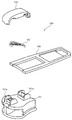
- FIGS. 6 and 7 are perspective views and side views showing the slider according to the second embodiment.
- 8 and 9 are a plan view and a side view showing a slider body of the slider according to the second embodiment. In FIGS. 6 to 9, the pull tab is not shown.
- the slider 2 for a slide fastener according to the second embodiment does not have an automatic stop mechanism by the stop claw body 50 like the slider 1 of the first embodiment described above, and is formed as a so-called free slider 2.
- a slider 2 of the second embodiment is formed of three parts: a slider body 70, a pull tab (not shown), and a cover body 90.
- the pull tab 40 described in the first embodiment can be used.
- the slider fuselage 70 of the second embodiment is the upper wing plate 80, the lower wing plate 71, the connecting pillar 72 connecting the front end portion of the upper wing plate 80 and the front end portion of the lower wing plate 71, and the upper wing plate 80. It has left and right upper flange portions 73 provided on the left and right portions. Further, the slider body 70 is provided behind the front mounting column 81 and the rear mounting column 82 rising upward from the upper wing plate 80, the front concave groove portion 83 provided in front of the front mounting column 81, and the rear mounting column 82. It has a rear concave groove portion 84 provided.
- the front mounting column 81 of the second embodiment is more than the front base portion 81a arranged in the central portion in the width direction of the upper wing plate 80, the pair of left and right front side first side wall portions 81b, and the front side first side wall portion 81b. It has a pair of left and right front second side wall portions 81c arranged in the front, and a front engaging claw portion 81d projecting forward from the front base portion 81a.
- the front side first side wall portion 81b, the front side second side wall portion 81c, and the front side engaging claw portion 81d of the second embodiment are formed substantially in the same manner as the front side mounting column 21 of the first embodiment.
- the left and right front side first side wall portions 81b in the second embodiment have a flat outer wall surface arranged orthogonally to the width direction of the slider 2, and the front side first side wall portion 81b.
- the outer wall surface is exposed to the outside.
- the upper end surface of the front side first side wall portion 81b has an upper end surface arranged in parallel with the upper surface of the upper blade plate 80, and the upper end surface of the front side first side wall portion 81b is left and right of the cover body portion 91. It is in contact with the lower end portion (lower end edge 96) of the side surface portion 95. As a result, the cover body 90 is supported from below.
- the left and right front second side wall portions 81c of the front side mounting pillar 81 extend forward from the front side first side wall portion 81b via the step portion 81g.
- the outer wall surface of the front second side wall portion 81c is formed on a flat surface orthogonal to the width direction, and is arranged inside the outer wall surface of the front side first side wall portion 81b via the step portion 81g. ing.
- the flat outer wall surface of the left and right front second side wall portions 81c is arranged in contact with or close to the inner wall surface of the front leg portion 92 of the cover body 90, and the front side second side wall portion 81c is arranged in the side view of the slider 2.
- a wide area is secured where the outer wall surface and the inner wall surface of the cover body 90 come into contact with each other or overlap with each other.
- the cover body 90 can be made difficult to tilt in the width direction, and the attachment strength of the cover body 90 to the slider body 70 can be increased.
- the front engaging claw portion 81d of the second embodiment faces the upper surface of the claw and the tip of the front engaging claw portion 81d from the upper surface of the claw when the cross section orthogonal to the width direction of the front engaging claw portion 81d is viewed. It has an inclined surface that is inclined downward, and a claw lower surface 81h that is arranged from the tip end portion of the front side engaging claw portion 81d to the front end surface of the front side base portion 81a.
- the claw lower surface 81h of the front engaging claw portion 81d has a concave curved surface curved in an arc shape in a cross section orthogonal to the width direction.
- the load applied from the cover body 90 to the front engaging claw portion 81d can be easily dispersed, and the front engaging claw portion 81d and the front base portion 81a are damaged. Can be suppressed.
- the rear mounting column 82 of the second embodiment has a rear base portion 82a arranged at the center in the width direction of the upper wing plate 80, a pair of left and right rear first side wall portions 82b, and a rear side first side wall portion. It has a pair of left and right rear second side wall portions 82c arranged outside (rear) in the length direction from the portion 82b, and a rear engaging claw portion 82d protruding rearward from the rear base portion 82a.
- the rear side first side wall portion 82b, the rear side second side wall portion 82c, and the rear side engaging claw portion 82d in the rear side mounting column 82 of the second embodiment are the front side first side wall portion 81b corresponding to the front side mounting column 81.
- the front side second side wall portion 81c and the front side engaging claw portion 81d are formed in the opposite directions in the front-rear direction, they are formed substantially in the same manner as the corresponding portions of the front side mounting column 81.
- the left and right rear second side wall portions 82c of the rear side mounting column 82 extend rearward from the rear side first side wall portion 82b via the step portion 82g.
- the outer wall surface of the rear second side wall portion 82c is formed on a flat surface orthogonal to the width direction, and is inside the outer wall surface of the rear side first side wall portion 82b via the step portion 82g. It is arranged.
- the outer wall surface of the left and right rear second side wall portions 82c is arranged in contact with or close to the inner wall surface of the rear leg portion 93 of the cover body 90.
- the rear engaging claw portion 82d has a claw lower surface 82h arranged from the tip end portion of the rear engaging claw portion 82d to the rear end surface of the rear side base portion 82a.
- the front end portion of the upper wing plate 80 is provided with a front concave groove portion 83 capable of accommodating the front lower end portion of the cover body 90, and the rear end portion of the upper wing plate 80 is provided with a rear lower end portion of the cover body 90.
- the rear concave groove portion 84 capable of accommodating the above is provided.
- the cover body 90 of the second embodiment has a cover body portion 91, a front leg portion 92 that bends downward from the front end portion of the cover body portion 91, and a rear leg that bends downward and extends from the rear end portion of the cover body portion 91. It has a part 93.
- the cover body 90 is formed so as to be elastically deformable.
- the cover body 90 extends from the front leg portion 92 to the rear leg portion 93 via the cover body portion 91, and extends from the left and right side edges of the cover main body portion 94 toward the inner peripheral side of the cover main body portion 94. It has left and right side surface portions 95, and the cover main body portion 94 forms a front surface portion of the front leg portion 92, an upper surface portion of the cover body portion 91, and a rear surface portion of the rear leg portion 93.
- the left and right side surface portions 95 of the cover body 90 are continuously provided over the front leg portion 92, the cover body portion 91, and the rear leg portion 93.
- the inner peripheral side edge edges of the left and right side surface portions 95 of the cover body 90 are provided on the lower end edge 96 provided on the cover body portion 91, the front leg portion 92 and the rear leg portion 93, and are arranged diagonally in the vertical direction. Has an inclined edge.
- the lower end edge 96 of the side surface portion 95 of the cover body portion 91 is the upper end portion (upper surface) of the left and right front side first side wall portions 81b of the front side mounting column 81 in the slider body portion 70, and the left and right rear side firsts of the rear side mounting column 82. 1
- the cover body 90 is supported by the slider body 70 at four points in contact with the upper end portion (upper surface) of the side wall portion 82b.
- the slider 2 of the second embodiment can have high strength against the load applied from the upper side of the cover body 90.
- the left and right side surface portions 95 arranged on the front leg portion 92 of the cover body 90 are arranged in contact with or close to the outer wall surface of the front side second side wall portion 81c of the front side mounting column 81.
- the left and right side surface portions 95 arranged on the rear leg portion 93 of the cover body 90 are arranged in contact with or close to the outer wall surface of the rear side second side wall portion 82c of the rear side mounting column 82.
- the front engaging claw portion 81d provided on the front mounting column 81 of the slider body 70 and the rear engaging claw portion 82d provided on the rear mounting column 82 A storage hole 99 is provided for inserting and accommodating each of the above.
- the accommodating hole 99 penetrates the cover body 90 in a straight line along the length direction.
- the front engaging claw portion 81d and the rear engaging claw portion 82d of the slider body 70 are accommodated in the respective accommodating holes 99 of the front leg portion 92 and the rear leg portion 93 in the cover body 90, so that the cover body 90 is a slider. It is attached by engaging with the fuselage 70.
- the attachment strength of the cover body 90 to the slider body 70 can be increased as in the slider 1 of the first embodiment described above, and the cover body 90 can be increased. It can show high strength against the load applied from above.
- the front leg portion 92 and / or the rear leg portion 93 of the cover body 90 is provided on the front side mounting column 81 and / or the rear side mounting column 82 of the slider body 70. Since the portions 81g and 82g can guide the cover body 90, it is possible to prevent the position of the cover body 90 (particularly the position in the width direction) from shifting with respect to the slider body 70, and to smoothly and stably assemble the cover body 90.
- the slider 1 of the first embodiment is mainly used for a slide fastener having a fastener element made of synthetic resin formed by injection molding.
- the slider 2 of the second embodiment is mainly used for a slide fastener having a coiled fastener element.
- the slider of the present invention can also be used for slide fasteners having various forms of fastener elements such as synthetic resin fastener elements, coiled fastener elements, and metal fastener elements formed by injection molding. It can be applied in the same way.
Landscapes
- Slide Fasteners (AREA)
Priority Applications (5)
| Application Number | Priority Date | Filing Date | Title |
|---|---|---|---|
| US17/928,093 US12096826B2 (en) | 2020-06-08 | 2020-06-08 | Slider |
| PCT/JP2020/022560 WO2021250748A1 (ja) | 2020-06-08 | 2020-06-08 | スライダー |
| EP20940049.8A EP4162834A4 (en) | 2020-06-08 | 2020-06-08 | PUSH |
| CN202080101808.2A CN115768302B (zh) | 2020-06-08 | 2020-06-08 | 拉头 |
| JP2022530373A JPWO2021250748A1 (https=) | 2020-06-08 | 2020-06-08 |
Applications Claiming Priority (1)
| Application Number | Priority Date | Filing Date | Title |
|---|---|---|---|
| PCT/JP2020/022560 WO2021250748A1 (ja) | 2020-06-08 | 2020-06-08 | スライダー |
Publications (1)
| Publication Number | Publication Date |
|---|---|
| WO2021250748A1 true WO2021250748A1 (ja) | 2021-12-16 |
Family
ID=78845460
Family Applications (1)
| Application Number | Title | Priority Date | Filing Date |
|---|---|---|---|
| PCT/JP2020/022560 Ceased WO2021250748A1 (ja) | 2020-06-08 | 2020-06-08 | スライダー |
Country Status (5)
| Country | Link |
|---|---|
| US (1) | US12096826B2 (https=) |
| EP (1) | EP4162834A4 (https=) |
| JP (1) | JPWO2021250748A1 (https=) |
| CN (1) | CN115768302B (https=) |
| WO (1) | WO2021250748A1 (https=) |
Cited By (1)
| Publication number | Priority date | Publication date | Assignee | Title |
|---|---|---|---|---|
| JPWO2023223397A1 (https=) * | 2022-05-16 | 2023-11-23 |
Families Citing this family (1)
| Publication number | Priority date | Publication date | Assignee | Title |
|---|---|---|---|---|
| USD1026729S1 (en) * | 2020-06-09 | 2024-05-14 | Hualian Garment Accessories Enterprises Co., Ltd | Slider |
Citations (3)
| Publication number | Priority date | Publication date | Assignee | Title |
|---|---|---|---|---|
| JP2006055435A (ja) * | 2004-08-20 | 2006-03-02 | Ykk Corp | 停止装置付スライドファスナー用スライダー |
| WO2009133617A1 (ja) | 2008-05-01 | 2009-11-05 | Ykk株式会社 | 自動停止装置付スライドファスナー用スライダー |
| JP3202594U (ja) * | 2015-03-13 | 2016-02-12 | 中傳企業股▲ふん▼有限公司 | ねじり強度を高めるためのファスナーヘッド組み合わせ構造及びそのスライダー |
Family Cites Families (22)
| Publication number | Priority date | Publication date | Assignee | Title |
|---|---|---|---|---|
| JPH0219048Y2 (https=) * | 1985-05-24 | 1990-05-28 | ||
| JPH0219049Y2 (https=) * | 1985-05-24 | 1990-05-28 | ||
| JPH08322611A (ja) * | 1995-05-31 | 1996-12-10 | Ykk Kk | 自動停止装置付スライドファスナー用スライダー |
| JP3393568B2 (ja) | 1995-08-31 | 2003-04-07 | ワイケイケイ株式会社 | 自動停止装置付スライドファスナー用スライダー |
| JPH09168412A (ja) * | 1995-12-21 | 1997-06-30 | Ykk Corp | スライドファスナー用スライダー |
| JP3393575B2 (ja) * | 1997-01-31 | 2003-04-07 | ワイケイケイ株式会社 | 自動停止装置付スライドファスナー用スライダー |
| CN1145432C (zh) * | 1997-12-10 | 2004-04-14 | 劦联股份有限公司 | 拉链拉头自动组装装置 |
| JP3935819B2 (ja) * | 2002-10-29 | 2007-06-27 | Ykk株式会社 | 自動停止装置付スライドファスナー用スライダー |
| JP4152254B2 (ja) * | 2003-05-21 | 2008-09-17 | Ykk株式会社 | スライドファスナー用スライダー |
| CH696621A5 (it) * | 2003-10-07 | 2007-08-31 | Crelux Holding Sa | Cursore con due tiretti. |
| US7257869B2 (en) * | 2006-01-17 | 2007-08-21 | Chung Chwan Enterprise Co., Ltd. | Zipper head assembly structure |
| CN200969925Y (zh) * | 2006-11-23 | 2007-11-07 | 驰马拉链(无锡)有限公司 | 改良的蝶形树脂拉链头 |
| KR101393210B1 (ko) * | 2010-04-02 | 2014-05-08 | 와이케이케이 가부시끼가이샤 | 슬라이드 파스너용 슬라이더 |
| KR101439071B1 (ko) * | 2010-09-29 | 2014-09-05 | 와이케이케이 가부시끼가이샤 | 슬라이드 파스너용 슬라이더 |
| EP2692261B1 (en) * | 2011-03-31 | 2017-04-26 | YKK Corporation | Slider for slide fastener with automatic stop device and method for manufacturing same |
| CN102763941A (zh) * | 2011-05-06 | 2012-11-07 | 福建浔兴拉链科技股份有限公司 | 拉头滑块及使用该拉头滑块的拉链头 |
| CN103190743A (zh) * | 2013-03-15 | 2013-07-10 | 晋江福兴拉链有限公司 | 一种新型拉链头及其弹片和帽盖 |
| TWI480008B (zh) * | 2013-05-20 | 2015-04-11 | Chung Chwan Entpr Co Ltd | 具有內表面凹陷特徵的帽蓋結構及拉鍊頭組合結構 |
| CN203884879U (zh) * | 2014-05-21 | 2014-10-22 | 福建浔兴拉链科技股份有限公司 | 方便装拆的拉链头 |
| CN204317693U (zh) * | 2014-11-29 | 2015-05-13 | 福建浔兴拉链科技股份有限公司 | 一种拉头帽盖的固定结构 |
| TWM509559U (zh) * | 2014-12-05 | 2015-10-01 | Chung Chwan Entpr Co Ltd | 具有多個破孔特徵的帽蓋結構及拉鍊頭組合結構 |
| WO2016139789A1 (ja) * | 2015-03-05 | 2016-09-09 | Ykk株式会社 | スライドファスナーのスライダー |
-
2020
- 2020-06-08 WO PCT/JP2020/022560 patent/WO2021250748A1/ja not_active Ceased
- 2020-06-08 US US17/928,093 patent/US12096826B2/en active Active
- 2020-06-08 JP JP2022530373A patent/JPWO2021250748A1/ja active Pending
- 2020-06-08 CN CN202080101808.2A patent/CN115768302B/zh active Active
- 2020-06-08 EP EP20940049.8A patent/EP4162834A4/en active Pending
Patent Citations (3)
| Publication number | Priority date | Publication date | Assignee | Title |
|---|---|---|---|---|
| JP2006055435A (ja) * | 2004-08-20 | 2006-03-02 | Ykk Corp | 停止装置付スライドファスナー用スライダー |
| WO2009133617A1 (ja) | 2008-05-01 | 2009-11-05 | Ykk株式会社 | 自動停止装置付スライドファスナー用スライダー |
| JP3202594U (ja) * | 2015-03-13 | 2016-02-12 | 中傳企業股▲ふん▼有限公司 | ねじり強度を高めるためのファスナーヘッド組み合わせ構造及びそのスライダー |
Non-Patent Citations (1)
| Title |
|---|
| See also references of EP4162834A4 |
Cited By (3)
| Publication number | Priority date | Publication date | Assignee | Title |
|---|---|---|---|---|
| JPWO2023223397A1 (https=) * | 2022-05-16 | 2023-11-23 | ||
| WO2023223397A1 (ja) * | 2022-05-16 | 2023-11-23 | Ykk株式会社 | スライダー |
| JP7710103B2 (ja) | 2022-05-16 | 2025-07-17 | Ykk株式会社 | スライダー |
Also Published As
| Publication number | Publication date |
|---|---|
| CN115768302B (zh) | 2026-03-17 |
| JPWO2021250748A1 (https=) | 2021-12-16 |
| EP4162834A4 (en) | 2023-07-19 |
| EP4162834A1 (en) | 2023-04-12 |
| US12096826B2 (en) | 2024-09-24 |
| CN115768302A (zh) | 2023-03-07 |
| US20230210227A1 (en) | 2023-07-06 |
Similar Documents
| Publication | Publication Date | Title |
|---|---|---|
| JP4540726B2 (ja) | 二部材組付け構造 | |
| US7789698B2 (en) | Connector for flat terminal | |
| JP5318228B2 (ja) | スライドファスナー用スライダー | |
| JP4257917B2 (ja) | シャッタ付電気コネクタ | |
| JP3203767U (ja) | スライドファスナー用スライダー | |
| JP6503273B2 (ja) | スライドファスナー用スライダー | |
| JP5809463B2 (ja) | フローティング型コネクタ | |
| JP2004344310A (ja) | スライドファスナー用スライダー | |
| JP2009013724A (ja) | ハンドル装置 | |
| WO2021250748A1 (ja) | スライダー | |
| JP5957091B2 (ja) | スライドファスナー用スライダー | |
| TWI440437B (zh) | Zipper with the slider | |
| US20110062762A1 (en) | Automotive seat headrest supporting apparatus | |
| CN110022715A (zh) | 拉链用拉头 | |
| CN107518534B (zh) | 拉链的拉头盖及拉头组 | |
| CN115003187B (zh) | 拉头 | |
| EP2737817A1 (en) | Slider for slide fastener | |
| WO2023248395A1 (ja) | スライドファスナー用スライダー | |
| WO2016139789A1 (ja) | スライドファスナーのスライダー | |
| WO2023157146A1 (ja) | スライドファスナー用スライダー及びこれを含むスライドファスナー | |
| JP3941643B2 (ja) | コネクタ | |
| KR102885710B1 (ko) | 파스너 브라켓 | |
| JP2004172067A (ja) | コネクタ | |
| JP2006147188A (ja) | 基板用コネクタにおける端子金具とアライメントプレートの組付け構造 | |
| CN115530492B (zh) | 拉片 |
Legal Events
| Date | Code | Title | Description |
|---|---|---|---|
| 121 | Ep: the epo has been informed by wipo that ep was designated in this application |
Ref document number: 20940049 Country of ref document: EP Kind code of ref document: A1 |
|
| ENP | Entry into the national phase |
Ref document number: 2022530373 Country of ref document: JP Kind code of ref document: A |
|
| NENP | Non-entry into the national phase |
Ref country code: DE |
|
| ENP | Entry into the national phase |
Ref document number: 2020940049 Country of ref document: EP Effective date: 20230109 |