WO2021245953A1 - ハイブリッド車両の制御方法及びハイブリッド車両の制御装置 - Google Patents
ハイブリッド車両の制御方法及びハイブリッド車両の制御装置 Download PDFInfo
- Publication number
- WO2021245953A1 WO2021245953A1 PCT/JP2020/024405 JP2020024405W WO2021245953A1 WO 2021245953 A1 WO2021245953 A1 WO 2021245953A1 JP 2020024405 W JP2020024405 W JP 2020024405W WO 2021245953 A1 WO2021245953 A1 WO 2021245953A1
- Authority
- WO
- WIPO (PCT)
- Prior art keywords
- engine
- rotation speed
- hybrid vehicle
- engine rotation
- battery
- Prior art date
- Legal status (The legal status is an assumption and is not a legal conclusion. Google has not performed a legal analysis and makes no representation as to the accuracy of the status listed.)
- Ceased
Links
Images


Classifications
-
- B—PERFORMING OPERATIONS; TRANSPORTING
- B60—VEHICLES IN GENERAL
- B60K—ARRANGEMENT OR MOUNTING OF PROPULSION UNITS OR OF TRANSMISSIONS IN VEHICLES; ARRANGEMENT OR MOUNTING OF PLURAL DIVERSE PRIME-MOVERS IN VEHICLES; AUXILIARY DRIVES FOR VEHICLES; INSTRUMENTATION OR DASHBOARDS FOR VEHICLES; ARRANGEMENTS IN CONNECTION WITH COOLING, AIR INTAKE, GAS EXHAUST OR FUEL SUPPLY OF PROPULSION UNITS IN VEHICLES
- B60K6/00—Arrangement or mounting of plural diverse prime-movers for mutual or common propulsion, e.g. hybrid propulsion systems comprising electric motors and internal combustion engines
- B60K6/20—Arrangement or mounting of plural diverse prime-movers for mutual or common propulsion, e.g. hybrid propulsion systems comprising electric motors and internal combustion engines the prime-movers consisting of electric motors and internal combustion engines, e.g. HEVs
- B60K6/42—Arrangement or mounting of plural diverse prime-movers for mutual or common propulsion, e.g. hybrid propulsion systems comprising electric motors and internal combustion engines the prime-movers consisting of electric motors and internal combustion engines, e.g. HEVs characterised by the architecture of the hybrid electric vehicle
- B60K6/46—Series type
-
- B—PERFORMING OPERATIONS; TRANSPORTING
- B60—VEHICLES IN GENERAL
- B60W—CONJOINT CONTROL OF VEHICLE SUB-UNITS OF DIFFERENT TYPE OR DIFFERENT FUNCTION; CONTROL SYSTEMS SPECIALLY ADAPTED FOR HYBRID VEHICLES; ROAD VEHICLE DRIVE CONTROL SYSTEMS FOR PURPOSES NOT RELATED TO THE CONTROL OF A PARTICULAR SUB-UNIT
- B60W10/00—Conjoint control of vehicle sub-units of different type or different function
- B60W10/04—Conjoint control of vehicle sub-units of different type or different function including control of propulsion units
- B60W10/06—Conjoint control of vehicle sub-units of different type or different function including control of propulsion units including control of combustion engines
-
- B—PERFORMING OPERATIONS; TRANSPORTING
- B60—VEHICLES IN GENERAL
- B60W—CONJOINT CONTROL OF VEHICLE SUB-UNITS OF DIFFERENT TYPE OR DIFFERENT FUNCTION; CONTROL SYSTEMS SPECIALLY ADAPTED FOR HYBRID VEHICLES; ROAD VEHICLE DRIVE CONTROL SYSTEMS FOR PURPOSES NOT RELATED TO THE CONTROL OF A PARTICULAR SUB-UNIT
- B60W10/00—Conjoint control of vehicle sub-units of different type or different function
- B60W10/24—Conjoint control of vehicle sub-units of different type or different function including control of energy storage means
- B60W10/26—Conjoint control of vehicle sub-units of different type or different function including control of energy storage means for electrical energy, e.g. batteries or capacitors
-
- B—PERFORMING OPERATIONS; TRANSPORTING
- B60—VEHICLES IN GENERAL
- B60W—CONJOINT CONTROL OF VEHICLE SUB-UNITS OF DIFFERENT TYPE OR DIFFERENT FUNCTION; CONTROL SYSTEMS SPECIALLY ADAPTED FOR HYBRID VEHICLES; ROAD VEHICLE DRIVE CONTROL SYSTEMS FOR PURPOSES NOT RELATED TO THE CONTROL OF A PARTICULAR SUB-UNIT
- B60W20/00—Control systems specially adapted for hybrid vehicles
- B60W20/10—Controlling the power contribution of each of the prime movers to meet required power demand
- B60W20/15—Control strategies specially adapted for achieving a particular effect
-
- B—PERFORMING OPERATIONS; TRANSPORTING
- B60—VEHICLES IN GENERAL
- B60W—CONJOINT CONTROL OF VEHICLE SUB-UNITS OF DIFFERENT TYPE OR DIFFERENT FUNCTION; CONTROL SYSTEMS SPECIALLY ADAPTED FOR HYBRID VEHICLES; ROAD VEHICLE DRIVE CONTROL SYSTEMS FOR PURPOSES NOT RELATED TO THE CONTROL OF A PARTICULAR SUB-UNIT
- B60W2510/00—Input parameters relating to a particular sub-units
- B60W2510/06—Combustion engines, Gas turbines
- B60W2510/0638—Engine speed
-
- B—PERFORMING OPERATIONS; TRANSPORTING
- B60—VEHICLES IN GENERAL
- B60W—CONJOINT CONTROL OF VEHICLE SUB-UNITS OF DIFFERENT TYPE OR DIFFERENT FUNCTION; CONTROL SYSTEMS SPECIALLY ADAPTED FOR HYBRID VEHICLES; ROAD VEHICLE DRIVE CONTROL SYSTEMS FOR PURPOSES NOT RELATED TO THE CONTROL OF A PARTICULAR SUB-UNIT
- B60W2510/00—Input parameters relating to a particular sub-units
- B60W2510/06—Combustion engines, Gas turbines
- B60W2510/0676—Engine temperature
-
- B—PERFORMING OPERATIONS; TRANSPORTING
- B60—VEHICLES IN GENERAL
- B60W—CONJOINT CONTROL OF VEHICLE SUB-UNITS OF DIFFERENT TYPE OR DIFFERENT FUNCTION; CONTROL SYSTEMS SPECIALLY ADAPTED FOR HYBRID VEHICLES; ROAD VEHICLE DRIVE CONTROL SYSTEMS FOR PURPOSES NOT RELATED TO THE CONTROL OF A PARTICULAR SUB-UNIT
- B60W2510/00—Input parameters relating to a particular sub-units
- B60W2510/24—Energy storage means
- B60W2510/242—Energy storage means for electrical energy
- B60W2510/244—Charge state
-
- B—PERFORMING OPERATIONS; TRANSPORTING
- B60—VEHICLES IN GENERAL
- B60W—CONJOINT CONTROL OF VEHICLE SUB-UNITS OF DIFFERENT TYPE OR DIFFERENT FUNCTION; CONTROL SYSTEMS SPECIALLY ADAPTED FOR HYBRID VEHICLES; ROAD VEHICLE DRIVE CONTROL SYSTEMS FOR PURPOSES NOT RELATED TO THE CONTROL OF A PARTICULAR SUB-UNIT
- B60W2710/00—Output or target parameters relating to a particular sub-units
- B60W2710/06—Combustion engines, Gas turbines
- B60W2710/0644—Engine speed
-
- B—PERFORMING OPERATIONS; TRANSPORTING
- B60—VEHICLES IN GENERAL
- B60W—CONJOINT CONTROL OF VEHICLE SUB-UNITS OF DIFFERENT TYPE OR DIFFERENT FUNCTION; CONTROL SYSTEMS SPECIALLY ADAPTED FOR HYBRID VEHICLES; ROAD VEHICLE DRIVE CONTROL SYSTEMS FOR PURPOSES NOT RELATED TO THE CONTROL OF A PARTICULAR SUB-UNIT
- B60W2710/00—Output or target parameters relating to a particular sub-units
- B60W2710/06—Combustion engines, Gas turbines
- B60W2710/0666—Engine torque
-
- B—PERFORMING OPERATIONS; TRANSPORTING
- B60—VEHICLES IN GENERAL
- B60W—CONJOINT CONTROL OF VEHICLE SUB-UNITS OF DIFFERENT TYPE OR DIFFERENT FUNCTION; CONTROL SYSTEMS SPECIALLY ADAPTED FOR HYBRID VEHICLES; ROAD VEHICLE DRIVE CONTROL SYSTEMS FOR PURPOSES NOT RELATED TO THE CONTROL OF A PARTICULAR SUB-UNIT
- B60W2710/00—Output or target parameters relating to a particular sub-units
- B60W2710/24—Energy storage means
- B60W2710/242—Energy storage means for electrical energy
- B60W2710/244—Charge state
-
- B—PERFORMING OPERATIONS; TRANSPORTING
- B60—VEHICLES IN GENERAL
- B60Y—INDEXING SCHEME RELATING TO ASPECTS CROSS-CUTTING VEHICLE TECHNOLOGY
- B60Y2200/00—Type of vehicle
- B60Y2200/90—Vehicles comprising electric prime movers
- B60Y2200/92—Hybrid vehicles
-
- Y—GENERAL TAGGING OF NEW TECHNOLOGICAL DEVELOPMENTS; GENERAL TAGGING OF CROSS-SECTIONAL TECHNOLOGIES SPANNING OVER SEVERAL SECTIONS OF THE IPC; TECHNICAL SUBJECTS COVERED BY FORMER USPC CROSS-REFERENCE ART COLLECTIONS [XRACs] AND DIGESTS
- Y02—TECHNOLOGIES OR APPLICATIONS FOR MITIGATION OR ADAPTATION AGAINST CLIMATE CHANGE
- Y02T—CLIMATE CHANGE MITIGATION TECHNOLOGIES RELATED TO TRANSPORTATION
- Y02T10/00—Road transport of goods or passengers
- Y02T10/60—Other road transportation technologies with climate change mitigation effect
- Y02T10/62—Hybrid vehicles
Definitions
- the present invention relates to a control method and a control device for a hybrid vehicle.
- JP2010-100103A discloses a control for operating an engine at an inefficient operating point (for example, an operating point deviating from the optimum fuel consumption line) in order to promote warming up of the engine. According to the control of the above document, the efficiency of the engine is lowered, so that the heat loss is increased, and the heat promotes the warming up of the engine.
- an inefficient operating point for example, an operating point deviating from the optimum fuel consumption line
- an object of the present invention is to provide a control method and a control device capable of improving fuel efficiency during engine warm-up.
- a control method for a hybrid vehicle including a traveling motor, a battery for supplying electric power to the traveling motor, and a power generation engine capable of supplying electric power to the battery and the traveling motor.
- the engine is operated at a higher engine rotation speed than the operating state in which the fuel-efficient device operates in the operating state in which the fuel-efficient device that contributes to the improvement of the fuel efficiency performance does not operate.
- FIG. 1 is a schematic configuration diagram of a control system for a series hybrid vehicle.
- FIG. 2 is a diagram showing an optimum fuel consumption line.
- FIG. 3 is a control block diagram for controlling the engine rotation speed.
- FIG. 4 is a control block diagram showing the processing contents of the ⁇ -ray calculation unit of FIG.
- FIG. 5 is a block diagram showing the processing contents of the engine rotation speed arbitration unit of FIG.
- FIG. 6 is a timing chart when the control of the present embodiment is executed.
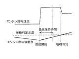
- FIG. 7 is a timing chart when warming up is completed after the lapse of the minimum holding time.
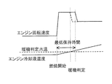
- FIG. 8 is a timing chart when warm-up is completed before the lapse of the minimum holding time.
- FIG. 1 is a schematic configuration diagram of a control system for a series hybrid vehicle, which is a premise of the present embodiment.
- the series hybrid vehicle includes a traveling motor 8, a battery 11 that supplies electric power to the traveling motor 8, and a power generation engine 13 that can supply electric power to the battery 11 and the traveling motor 8.
- the electric power supplied to the battery 11 and the traveling motor 8 is mainly generated by the power generation motor 10 driven by the engine 13.
- the control system of this series hybrid vehicle mainly includes a vehicle control module (VCM) 1, an engine control module (ECM) 12, a vehicle dynamics controller (VDC) 5, and a battery controller (LBC) 4. These are connected so as to be capable of information communication by a so-called controller area network (CAN).
- VCM vehicle control module
- ECM engine control module
- VDC vehicle dynamics controller
- LBC battery controller
- the VCM 1 includes a power generation request power calculation unit 2 including an ⁇ -ray calculation unit 2A for calculating an optimum fuel efficiency line (hereinafter, also referred to as an ⁇ -ray), a target power generation engine operation calculation unit 3 including an engine rotation speed arbitration unit 3A, and a target power generation engine operation calculation unit 3.
- An engine mode determination unit 6 for determining an operation mode of the engine 13 is provided.
- the configuration in VCM1 shows the function as a block diagram, and does not mean a physical configuration. Further, ⁇ rays will be described later.
- the motor drive target calculation unit 4 is requested to generate power by the wheel speed from the VDC 5, the accelerator opening from the accelerator opening sensor (not shown), and the actual rotation speed of the traveling motor (also referred to as the actual motor rotation speed) from the motor inverter 7.
- the upper limit motor torque is input from the power calculation unit 2.
- the power generation request power calculation unit 2 calculates the target torque (also referred to as the target motor torque) of the traveling motor 8 and the drive request power generation power by a known method based on the input value.
- the target motor torque is input to the motor inverter 7, and the motor inverter 7 controls the traveling motor 8 based on the target motor torque.
- the power generation request power calculation unit 2 receives the engine coolant temperature and the actual engine rotation speed from the ECM 12, the SOC of the battery 11 from the LBC 4, the discharge upper limit power and the charge upper limit power, and a manner mode signal or a charge mode signal from a mode selector (not shown). Is entered. The power generation request power calculation unit 2 calculates the upper limit motor torque, the target power generation power, and the like based on the input values. The details of the ⁇ -ray calculation unit 2A will be described later.
- the target power generation engine operation calculation unit 3 calculates the target engine rotation speed and the target engine torque based on the target power generation power and the engine mode flag determined by the engine mode determination unit 6.
- the target engine rotation speed is input to the generator inverter 9, and the generator inverter 9 controls the power generation motor 10 based on the target engine rotation speed.
- the target engine torque is input to the ECM 12, and the ECM 12 controls the engine 13 based on the target engine torque and the fuel cut flag determined by the engine mode determination unit 6.
- the ECM 12 As an engine control for a series hybrid vehicle, the ECM 12 basically operates the engine 13 for charging according to the charge rate (SOC) of the battery 11. At that time, the ECM 12 gives priority to fuel efficiency and operates the engine 13 at the operating point having the lowest fuel efficiency on the optimum fuel efficiency line (also referred to as ⁇ ray).
- the optimum fuel consumption line is an operating line connecting the operating points having the highest fuel efficiency in order to obtain the output for each output.
- the engine 13 when the engine 13 is started in a cold state, it is known to control the engine 13 to operate at an operating point deviated from ⁇ rays in order to promote warming up. According to this control, the fuel efficiency is lowered by setting the operating point outside the ⁇ ray, in other words, the heat loss is increased, so that the heat receiving amount of the engine 13 is increased and the warm-up is promoted.
- the engine 13 in order to suppress the deterioration of the fuel efficiency performance, the engine 13 is operated at the operating point on the ⁇ line even in the operating state before warming up.
- the engine 13 is provided with a variable valve gear (VTC), an exhaust gas recirculation device (EGR), and a knocking control device as devices (fuel consumption devices) that contribute to the improvement of fuel consumption performance.
- VTC variable valve gear
- EGR exhaust gas recirculation device
- a knocking control device as devices (fuel consumption devices) that contribute to the improvement of fuel consumption performance.
- the ⁇ -ray is different depending on whether it is not operating.
- the ⁇ -rays are different between the operating state in which the fuel-efficient device such as VTC or EGR is not operating as immediately after the start of the cold engine 13 and the operating state after the warm-up is completed in which the fuel-efficient device is operated. Comparing the state where the engine coolant temperature is medium water temperature after the start of cooling and before the completion of warming up and the state after warming up, as shown in FIG. 2, the operating point with the lowest fuel consumption rate at medium water temperature (in the figure). Point A) has a higher engine output than that after warming up (point B in the figure).
- the ⁇ ray to be used is switched according to the operation / non-operation of the fuel efficiency device.
- the details of the engine control at the medium water temperature in the present embodiment will be described.
- FIG. 3 is a control block diagram of an ⁇ -ray calculation unit 2A and an engine rotation speed arbitration unit 3A for controlling an engine at a medium water temperature according to the present embodiment. Although FIG. 3 also shows a generated power arbitration unit and an engine torque arbitration unit, these are not unique to the present invention.
- the ⁇ -ray calculation unit 2A outputs a fixed point output to the generated power arbitration unit, an ⁇ -ray rotation speed and a lower limit rotation speed to the engine rotation speed arbitration unit 3A, and an ⁇ -ray torque to the engine torque arbitration unit.
- the fixed point output is the engine output at the operating point of the engine 13.
- the ⁇ -ray rotation speed is the engine rotation speed at the operating point when the engine 13 is operated at the operating point on the ⁇ -ray.
- the ⁇ -ray rotation speed is calculated based on the engine output at the operating point A in FIG. 2 if the water temperature is medium, and is calculated based on the engine output at the operating point B in FIG. 2 after warming up.
- the lower limit rotation speed is the lower limit value of the engine rotation speed calculated by the calculation described later.
- the ⁇ -ray torque is the engine torque at the operating point when the engine 13 is operated at the operating point on the ⁇ -ray.
- the ⁇ -ray torque is calculated based on the engine output at the operating point A or the operating point B on the ⁇ -ray, as in the case of the ⁇ -ray rotation speed, for example.
- the characteristic part in this embodiment is that the lower limit rotation speed is calculated by the ⁇ -ray calculation unit 2A and output to the engine rotation speed arbitration unit 3A.
- the processing in the engine rotation speed arbitration unit 3A will be described later.
- FIG. 4 shows a function for calculating the lower limit rotation speed in the ⁇ -ray calculation unit 2A as a control block diagram.
- ⁇ -rays at medium water temperature that is, an operating state in which the fuel-efficient device does not operate
- ⁇ -rays after warming up that is, an operating state in which the fuel-efficient device operates
- the engine state determination unit 40 reads the above ⁇ -ray flag, and further determines whether the engine 13 is in a combustion state or a non-combustion state.
- the non-combustion state also includes idle operation.
- the engine state determination unit 40 sets the state flag to 1 if it is in a non-combustion state, and sets the state flag to zero if it is in a combustion state.
- the first warm-up determination unit 41 determines whether or not the first warm-up has been completed on this trip. One trip is from ignition on (that is, power on of the hybrid system) to ignition off (that is, power off of the hybrid system). The first warm-up determination unit 41 sets the warm-up completion flag to 1 when the first warm-up in this trip is completed, and sets the warm-up completion flag to zero when it is before the completion.
- the flag determination unit 42 determines whether or not the condition that the status flag is zero and the warm-up completion flag is zero is satisfied. When the condition is satisfied, the lower limit setting unit 43 determines (sets) the setting of the lower limit rotation speed. Further, the lower limit setting unit 43 clears each of the above flags when the start-up reset flag, which means the start of the trip, is input.
- the rate processing unit 44 sets the change speed of the engine rotation speed when the limitation of the engine rotation speed due to the lower limit rotation speed is released after the warm-up is completed, and then the setting is performed. And the change speed is output to the switch 45.
- the switch 45 selects the medium water temperature lower limit rotation speed when the lower limit rotation speed is set, selects -9999 as the rotation speed otherwise, and outputs the selected value to the engine rotation speed arbitrator 3A.
- the rotation speed of -9999 means that the lower limit rotation speed is not limited.
- the lower limit rotation speed of the medium water temperature is, for example, around 2000 [rpm].
- FIG. 5 shows a function for setting the engine rotation speed in the engine rotation speed arbitration unit 3A as a control block diagram.
- the engine rotation speed arbitration unit 3A determines the engine rotation speed in three stages.
- the engine rotation speed based on ⁇ rays is compared with the engine rotation speed limited by the driving force and the limit value determined by the vehicle speed, and the lower one is selected.
- the above limit value is an upper limit value of the engine rotation speed for making the operating noise of the engine inconspicuous when the driving force is small or the vehicle speed is low.
- the limit value that changes according to the driving force and the vehicle speed is mapped in advance, and the above limit value is determined based on this map.
- the engine rotation speed selected above, the fuel consumption required lower limit rotation speed, the charge mode lower limit rotation speed, and the sound vibration required lower limit rotation speed are compared, and the highest engine rotation speed is selected.
- the fuel consumption required lower limit rotation speed is the lower limit engine rotation speed determined based on the ⁇ rays at the above-mentioned medium water temperature.
- the lower limit rotation speed of the charge mode is the lower limit engine rotation speed when the charge mode described later is executed.
- the charge mode is an operation mode for increasing the SOC of the battery 11, which is executed according to the switch operation of the driver. Even when the charge mode is not executed, the engine 13 is controlled to increase the amount of power generation if the SOC of the battery 11 drops to the lower limit of discharge, but in the charge mode, if the SOC of the battery 11 is equal to or less than the upper limit of charging, the SOC is controlled. Regardless, the engine speed increases in order to increase the amount of power generation.
- the lower limit rotation speed required for sound vibration is the lower limit engine rotation speed that satisfies the demand for suppressing noise and vibration (so-called sound vibration requirement).
- the heating request upper limit rotation speed, the charge mode upper limit rotation speed, the SOC control upper limit rotation speed, and the engine rotation speed selected in the second stage are compared, and the lowest engine rotation speed is selected. ..
- the heating requirement upper limit rotation speed is the upper limit engine rotation speed when executing heating control, which is a control for raising the engine coolant temperature so as to satisfy the heating requirement.
- heating control is executed, if the engine is operated at an operating point on the ⁇ -ray, the amount of heat generated by the engine 13 is low, so that the temperature of the engine coolant is unlikely to rise. In other words, the operating time of the engine 13 for raising the engine coolant temperature becomes long. Then, as the operating time of the engine 13 becomes longer, the SOC of the battery 11 may rise excessively. Therefore, when the heating control is executed, in order to prevent the SOC of the battery 11 from excessively rising, a heating request upper limit rotation speed lower than the operating point on the ⁇ -ray is set.
- the engine rotation speed that can suppress the decrease in the fuel efficiency performance while suppressing the excessive increase in the SOC of the battery 11 is set to the upper limit rotation speed required for heating.
- Speed Specifically, it is set according to the specifications of the engine 13, the capacity of the battery 11, and the like.
- the SOC management upper limit rotation speed is the upper limit engine rotation speed when the SOC management control, which is a control for keeping the SOC of the battery 11 within the range from the dischargeable lower limit value to the chargeable upper limit value, is executed. Since the SOC management control is a control generally performed in a hybrid vehicle, the description thereof will be omitted.
- the above heating required upper limit rotation speed, charge mode upper limit rotation speed, and SOC management upper limit rotation speed are all engine rotation speeds for preventing the SOC of the battery 11 from increasing excessively. That is, in the present embodiment, even if the lower limit rotation speed required for fuel efficiency is selected in the second stage, if the engine rotation speed for preventing the SOC of the battery 11 from increasing excessively in the third stage is lower. The engine rotation speed finally selected is the engine rotation speed for preventing the SOC of the battery 11 from increasing excessively.
- the upper limit rotation speed required for heating changes when the warm-up of the engine 13 is completed.
- FIG. 6 is a timing chart when the control of the present embodiment is executed.
- the solid line shows the case where the control of this embodiment is executed
- the alternate long and short dash line is a comparative example, specifically, warmed up at the above-mentioned operating point with poor fuel efficiency. Shows the case. Since the engine output and the engine rotation speed are in a proportional relationship as described above, the engine output chart can be replaced with the engine rotation speed.
- a warm-up request for the engine 13 occurs at timing T1, and the engine output increases accordingly.
- the engine 13 is operated at an engine rotation speed based on ⁇ rays for medium water temperature or an engine rotation speed higher than that, so that the engine output (engine rotation speed) is higher than that of the comparative example.
- the warm-up request continues until the timing T2 when the engine coolant temperature becomes slightly lower than the warm-up threshold.
- the reason why the warm-up request is terminated even though the warm-up threshold value has not been reached at the timing T2 is due to another control performed in parallel with the control of the present embodiment. Therefore, without such a requirement, the warm-up requirement continues until the engine coolant temperature reaches the warm-up threshold. Further, the engine has been operating since before the timing T1, but this is an operation according to the catalyst warm-up request flag set by a routine different from the control of the present embodiment.
- the engine 13 stops at timing T2 and then operates again at timing T3. This is a requirement based on the SOC control of the battery 11, for example, the operation due to the selection of the charge mode. Since the warm-up has not been completed here either, the engine 13 operates at the same engine rotation speed as the timings T1-T2.
- the engine coolant temperature reaches the warm-up threshold.
- the engine output does not decrease immediately. This is because the minimum holding time of the lower limit rotation speed is provided in the present embodiment.
- the reason for providing the minimum holding time is that the driver may feel annoyed if the engine rotation speed fluctuates in a short time, for example, when the warm-up is completed immediately after starting the engine.
- the specific minimum holding time is set by conformity or the like, but is set to, for example, about 3-5 seconds.
- the engine rotation speed is reduced at the change speed set by the rate processing unit 44 described above.
- the first warm-up completion flag becomes 1.
- the control of the present embodiment is not executed. This is because if the engine rotation speed is different each time the engine is started after the warm-up is completed once, the driver or the like may feel uncomfortable.
- FIG. 7 shows the case where the warm-up is completed after the minimum holding time has elapsed.
- FIG. 8 shows the case where the warm-up is completed before the lapse of the minimum holding time.
- the restriction by the lower limit rotation speed of the engine rotation speed is released at the timing when the warm-up is completed as shown in FIG. 7, and the engine rotation speed is lowered.
- the limitation due to the lower limit rotation speed of the engine rotation speed is released at the timing when the minimum holding time elapses as shown in FIG. 8, and the engine rotation speed is lowered. ..
- the minimum holding time count is started every time the warm-up operation is started. For example, when the engine 13 is started at the timing T3 in FIG. 8, the count is started.
- the rate of change when reducing the engine speed can be set arbitrarily. For example, a change speed that does not give a sense of discomfort to the driver or the like due to a sharp decrease is set by adaptation or the like.
- the traveling motor 8, the battery 11 that supplies electric power to the traveling motor 8, and the power generation engine 13 that can supply electric power to the battery 11 and the traveling motor 8 are provided.
- a method of controlling a hybrid vehicle is provided.
- the engine in the operating state in which the fuel-efficient device that contributes to the improvement of the fuel-efficient performance is not operated, the engine is operated at a higher engine rotation speed than the operating state in which the fuel-efficient device is operated.
- the lower limit rotation speed of the engine 13 is set higher than in the operating state in which the fuel consumption device operates.
- the fuel consumption device it is determined based on the engine coolant temperature whether or not the fuel consumption device is in the operating state. Thereby, it is possible to determine whether or not the fuel consumption device is in the operating state by using the water temperature sensor included in the general engine 13.
- the engine rotation speed is maintained in the operating state in which the fuel consumption device is operated even if the engine coolant temperature drops during the trip. This makes it possible to prevent the driver and the like from giving a sense of discomfort due to the difference in engine rotation speed each time the engine 13 is started.
- the engine rotation speed is set in the operating state in which the fuel consumption device does not operate, the engine rotation speed is maintained for the preset minimum holding time. This makes it possible to prevent the driver or the like from feeling annoyed by the upper limit of the engine rotation speed in a short time.
- the upper limit engine rotation speed for suppressing an excessive increase in the charge rate (SOC) of the battery 11 and the lower limit rotation speed in the operating state in which the fuel consumption device is not operated are compared, and the lower engine is used. Drive at rotational speed. This makes it possible to suppress an excessive increase in the SOC of the battery 11.
- the upper limit engine rotation speed is the engine rotation speed for suppressing an excessive increase in the SOC of the battery 11 when the engine 13 is operated to increase the engine coolant temperature in response to a heating request. be.
Landscapes
- Engineering & Computer Science (AREA)
- Chemical & Material Sciences (AREA)
- Combustion & Propulsion (AREA)
- Transportation (AREA)
- Mechanical Engineering (AREA)
- Automation & Control Theory (AREA)
- Control Of Vehicle Engines Or Engines For Specific Uses (AREA)
- Hybrid Electric Vehicles (AREA)
Priority Applications (5)
| Application Number | Priority Date | Filing Date | Title |
|---|---|---|---|
| CN202080101645.8A CN115884907B (zh) | 2020-06-04 | 2020-06-22 | 混合动力车辆的控制方法及混合动力车辆的控制装置 |
| JP2022528408A JP7367869B2 (ja) | 2020-06-04 | 2020-06-22 | ハイブリッド車両の制御方法及びハイブリッド車両の制御装置 |
| EP20938998.0A EP4163171B1 (en) | 2020-06-04 | 2020-06-22 | Hybrid vehicle control method and hybrid vehicle control device |
| US17/928,792 US12208788B2 (en) | 2020-06-04 | 2020-06-22 | Hybrid vehicle control method and hybrid vehicle control device |
| MX2022015135A MX2022015135A (es) | 2020-06-04 | 2020-06-22 | Metodo de control de vehiculo hibrido y dispositivo de control de vehiculo hibrido. |
Applications Claiming Priority (2)
| Application Number | Priority Date | Filing Date | Title |
|---|---|---|---|
| JPPCT/JP2020/022144 | 2020-06-04 | ||
| JP2020022144 | 2020-06-04 |
Publications (1)
| Publication Number | Publication Date |
|---|---|
| WO2021245953A1 true WO2021245953A1 (ja) | 2021-12-09 |
Family
ID=78830764
Family Applications (1)
| Application Number | Title | Priority Date | Filing Date |
|---|---|---|---|
| PCT/JP2020/024405 Ceased WO2021245953A1 (ja) | 2020-06-04 | 2020-06-22 | ハイブリッド車両の制御方法及びハイブリッド車両の制御装置 |
Country Status (6)
| Country | Link |
|---|---|
| US (1) | US12208788B2 (https=) |
| EP (1) | EP4163171B1 (https=) |
| JP (1) | JP7367869B2 (https=) |
| CN (1) | CN115884907B (https=) |
| MX (1) | MX2022015135A (https=) |
| WO (1) | WO2021245953A1 (https=) |
Families Citing this family (1)
| Publication number | Priority date | Publication date | Assignee | Title |
|---|---|---|---|---|
| CN116888024B (zh) * | 2021-02-19 | 2025-04-01 | 日产自动车株式会社 | 串联式混合动力车辆的控制方法及控制装置 |
Citations (6)
| Publication number | Priority date | Publication date | Assignee | Title |
|---|---|---|---|---|
| JP2004143982A (ja) * | 2002-10-23 | 2004-05-20 | Suzuki Motor Corp | エンジンの回転数制御装置 |
| JP2004278340A (ja) * | 2003-03-13 | 2004-10-07 | Nissan Motor Co Ltd | ハイブリッド車両の制御装置 |
| JP2008168805A (ja) * | 2007-01-12 | 2008-07-24 | Toyota Motor Corp | 車両およびその制御方法 |
| JP2010100103A (ja) | 2008-10-21 | 2010-05-06 | Toyota Motor Corp | ハイブリッド車およびその制御方法 |
| JP2010241380A (ja) * | 2009-04-09 | 2010-10-28 | Toyota Motor Corp | ハイブリッド車両およびその制御方法 |
| WO2011046123A1 (ja) * | 2009-10-14 | 2011-04-21 | 日産自動車株式会社 | ハイブリッド車両の制御装置 |
Family Cites Families (6)
| Publication number | Priority date | Publication date | Assignee | Title |
|---|---|---|---|---|
| US6866610B2 (en) * | 2001-03-30 | 2005-03-15 | Toyota Jidosha Kabushiki Kaisha | Control apparatus and method for vehicle having internal combustion engine and continuously variable transmission, and control apparatus and method for internal combustion engine |
| JP4737098B2 (ja) * | 2007-01-24 | 2011-07-27 | 株式会社デンソー | 内燃機関の診断装置 |
| US7980342B2 (en) * | 2008-06-27 | 2011-07-19 | Ford Global Technologies, Llc | Plug-in hybrid electric vehicle |
| JP5765319B2 (ja) | 2012-11-16 | 2015-08-19 | トヨタ自動車株式会社 | ハイブリッド車両の制御システム及びハイブリッド車両 |
| KR101806616B1 (ko) * | 2015-09-17 | 2017-12-08 | 현대자동차주식회사 | 전기차량의 충전 제어 방법 |
| EP4212970A1 (en) * | 2022-01-17 | 2023-07-19 | Abb Schweiz Ag | Method for controlling operation of an electrolyzer plant |
-
2020
- 2020-06-22 US US17/928,792 patent/US12208788B2/en active Active
- 2020-06-22 WO PCT/JP2020/024405 patent/WO2021245953A1/ja not_active Ceased
- 2020-06-22 MX MX2022015135A patent/MX2022015135A/es unknown
- 2020-06-22 CN CN202080101645.8A patent/CN115884907B/zh active Active
- 2020-06-22 JP JP2022528408A patent/JP7367869B2/ja active Active
- 2020-06-22 EP EP20938998.0A patent/EP4163171B1/en active Active
Patent Citations (6)
| Publication number | Priority date | Publication date | Assignee | Title |
|---|---|---|---|---|
| JP2004143982A (ja) * | 2002-10-23 | 2004-05-20 | Suzuki Motor Corp | エンジンの回転数制御装置 |
| JP2004278340A (ja) * | 2003-03-13 | 2004-10-07 | Nissan Motor Co Ltd | ハイブリッド車両の制御装置 |
| JP2008168805A (ja) * | 2007-01-12 | 2008-07-24 | Toyota Motor Corp | 車両およびその制御方法 |
| JP2010100103A (ja) | 2008-10-21 | 2010-05-06 | Toyota Motor Corp | ハイブリッド車およびその制御方法 |
| JP2010241380A (ja) * | 2009-04-09 | 2010-10-28 | Toyota Motor Corp | ハイブリッド車両およびその制御方法 |
| WO2011046123A1 (ja) * | 2009-10-14 | 2011-04-21 | 日産自動車株式会社 | ハイブリッド車両の制御装置 |
Non-Patent Citations (1)
| Title |
|---|
| See also references of EP4163171A4 |
Also Published As
| Publication number | Publication date |
|---|---|
| EP4163171A4 (en) | 2023-11-29 |
| CN115884907B (zh) | 2025-09-23 |
| JPWO2021245953A1 (https=) | 2021-12-09 |
| US20230227020A1 (en) | 2023-07-20 |
| US12208788B2 (en) | 2025-01-28 |
| JP7367869B2 (ja) | 2023-10-24 |
| EP4163171B1 (en) | 2025-10-15 |
| MX2022015135A (es) | 2023-01-04 |
| EP4163171A1 (en) | 2023-04-12 |
| CN115884907A (zh) | 2023-03-31 |
Similar Documents
| Publication | Publication Date | Title |
|---|---|---|
| US7216729B2 (en) | Method and system of requesting engine on/off state in a hybrid electric vehicle | |
| JP3539406B2 (ja) | ハイブリッド車両の制御装置 | |
| JP3633357B2 (ja) | 車両のモータ駆動制御装置 | |
| US20080119975A1 (en) | Hybrid Electric Vehicle Powertrain with Engine Start and Transmission Shift Arbitration | |
| WO2022193721A1 (zh) | 混合动力汽车发电扭矩分配方法及混合动力汽车 | |
| JP2009035121A (ja) | ハイブリッド車両の内燃機関の始動制御装置 | |
| JP6136474B2 (ja) | ハイブリッド車の制御装置 | |
| JP5692140B2 (ja) | 駆動制御装置 | |
| CN114312341A (zh) | 电动车辆及其节能控制方法、装置 | |
| CN116674523A (zh) | 混合动力汽车的扭矩分配方法、装置、汽车及存储介质 | |
| JPH08168103A (ja) | ハイブリッド型電気自動車 | |
| JP7367869B2 (ja) | ハイブリッド車両の制御方法及びハイブリッド車両の制御装置 | |
| CN114412651B (zh) | 混动车辆及其催化器起燃的控制方法和控制装置 | |
| KR20110055286A (ko) | 하이브리드 차량의 제어방법 | |
| JP3915689B2 (ja) | 車両制御装置及びその車両制御装置を備えたハイブリッド車両 | |
| JP6881366B2 (ja) | 車両の制御システム | |
| JP2006275019A (ja) | ハイブリッド車の制御装置 | |
| JP2012066623A (ja) | 内燃機関の出力制御装置 | |
| KR102886279B1 (ko) | FATC 엔진 On 후 냉각을 고려한 엔진 On 라인의 가변 제어 시스템 | |
| JP4086053B2 (ja) | ハイブリッド式自動車の制御装置 | |
| JP2020184857A (ja) | 車両制御装置 | |
| CN117536724A (zh) | 发动机的控制方法、装置、车辆及车载终端 | |
| JP4318698B2 (ja) | 車両の動力切替制御方法 | |
| US20260084689A1 (en) | Control device for hybrid electric vehicle | |
| KR100792922B1 (ko) | 하이브리드 전기 차량의 제어기간 협조제어를 통한 시동시엔진 제어 방법 |
Legal Events
| Date | Code | Title | Description |
|---|---|---|---|
| 121 | Ep: the epo has been informed by wipo that ep was designated in this application |
Ref document number: 20938998 Country of ref document: EP Kind code of ref document: A1 |
|
| ENP | Entry into the national phase |
Ref document number: 2022528408 Country of ref document: JP Kind code of ref document: A |
|
| REG | Reference to national code |
Ref country code: BR Ref legal event code: B01A Ref document number: 112022024558 Country of ref document: BR |
|
| NENP | Non-entry into the national phase |
Ref country code: DE |
|
| ENP | Entry into the national phase |
Ref document number: 2020938998 Country of ref document: EP Effective date: 20230104 |
|
| ENP | Entry into the national phase |
Ref document number: 112022024558 Country of ref document: BR Kind code of ref document: A2 Effective date: 20221130 |
|
| WWG | Wipo information: grant in national office |
Ref document number: 202080101645.8 Country of ref document: CN |
|
| WWG | Wipo information: grant in national office |
Ref document number: 2020938998 Country of ref document: EP |