WO2021215148A1 - ソレノイド、減衰力調整機構および減衰力調整式緩衝器 - Google Patents
ソレノイド、減衰力調整機構および減衰力調整式緩衝器 Download PDFInfo
- Publication number
- WO2021215148A1 WO2021215148A1 PCT/JP2021/010774 JP2021010774W WO2021215148A1 WO 2021215148 A1 WO2021215148 A1 WO 2021215148A1 JP 2021010774 W JP2021010774 W JP 2021010774W WO 2021215148 A1 WO2021215148 A1 WO 2021215148A1
- Authority
- WO
- WIPO (PCT)
- Prior art keywords
- stator
- yoke
- coil
- damping force
- storage
- Prior art date
- Legal status (The legal status is an assumption and is not a legal conclusion. Google has not performed a legal analysis and makes no representation as to the accuracy of the status listed.)
- Ceased
Links
Images




Classifications
-
- F—MECHANICAL ENGINEERING; LIGHTING; HEATING; WEAPONS; BLASTING
- F16—ENGINEERING ELEMENTS AND UNITS; GENERAL MEASURES FOR PRODUCING AND MAINTAINING EFFECTIVE FUNCTIONING OF MACHINES OR INSTALLATIONS; THERMAL INSULATION IN GENERAL
- F16K—VALVES; TAPS; COCKS; ACTUATING-FLOATS; DEVICES FOR VENTING OR AERATING
- F16K31/00—Actuating devices; Operating means; Releasing devices
- F16K31/02—Actuating devices; Operating means; Releasing devices electric; magnetic
- F16K31/06—Actuating devices; Operating means; Releasing devices electric; magnetic using a magnet, e.g. diaphragm valves, cutting off by means of a liquid
- F16K31/0686—Braking, pressure equilibration, shock absorbing
- F16K31/0693—Pressure equilibration of the armature
-
- F—MECHANICAL ENGINEERING; LIGHTING; HEATING; WEAPONS; BLASTING
- F16—ENGINEERING ELEMENTS AND UNITS; GENERAL MEASURES FOR PRODUCING AND MAINTAINING EFFECTIVE FUNCTIONING OF MACHINES OR INSTALLATIONS; THERMAL INSULATION IN GENERAL
- F16F—SPRINGS; SHOCK-ABSORBERS; MEANS FOR DAMPING VIBRATION
- F16F9/00—Springs, vibration-dampers, shock-absorbers, or similarly-constructed movement-dampers using a fluid or the equivalent as damping medium
- F16F9/10—Springs, vibration-dampers, shock-absorbers, or similarly-constructed movement-dampers using a fluid or the equivalent as damping medium using liquid only; using a fluid of which the nature is immaterial
- F16F9/14—Devices with one or more members, e.g. pistons, vanes, moving to and fro in chambers and using throttling effect
- F16F9/16—Devices with one or more members, e.g. pistons, vanes, moving to and fro in chambers and using throttling effect involving only straight-line movement of the effective parts
- F16F9/18—Devices with one or more members, e.g. pistons, vanes, moving to and fro in chambers and using throttling effect involving only straight-line movement of the effective parts with a closed cylinder and a piston separating two or more working spaces therein
- F16F9/19—Devices with one or more members, e.g. pistons, vanes, moving to and fro in chambers and using throttling effect involving only straight-line movement of the effective parts with a closed cylinder and a piston separating two or more working spaces therein with a single cylinder and of single-tube type
-
- H—ELECTRICITY
- H01—ELECTRIC ELEMENTS
- H01F—MAGNETS; INDUCTANCES; TRANSFORMERS; SELECTION OF MATERIALS FOR THEIR MAGNETIC PROPERTIES
- H01F7/00—Magnets
- H01F7/06—Electromagnets; Actuators including electromagnets
- H01F7/08—Electromagnets; Actuators including electromagnets with armatures
- H01F7/16—Rectilinearly-movable armatures
- H01F7/1607—Armatures entering the winding
-
- F—MECHANICAL ENGINEERING; LIGHTING; HEATING; WEAPONS; BLASTING
- F16—ENGINEERING ELEMENTS AND UNITS; GENERAL MEASURES FOR PRODUCING AND MAINTAINING EFFECTIVE FUNCTIONING OF MACHINES OR INSTALLATIONS; THERMAL INSULATION IN GENERAL
- F16F—SPRINGS; SHOCK-ABSORBERS; MEANS FOR DAMPING VIBRATION
- F16F9/00—Springs, vibration-dampers, shock-absorbers, or similarly-constructed movement-dampers using a fluid or the equivalent as damping medium
- F16F9/32—Details
- F16F9/34—Special valve constructions; Shape or construction of throttling passages
-
- F—MECHANICAL ENGINEERING; LIGHTING; HEATING; WEAPONS; BLASTING
- F16—ENGINEERING ELEMENTS AND UNITS; GENERAL MEASURES FOR PRODUCING AND MAINTAINING EFFECTIVE FUNCTIONING OF MACHINES OR INSTALLATIONS; THERMAL INSULATION IN GENERAL
- F16F—SPRINGS; SHOCK-ABSORBERS; MEANS FOR DAMPING VIBRATION
- F16F9/00—Springs, vibration-dampers, shock-absorbers, or similarly-constructed movement-dampers using a fluid or the equivalent as damping medium
- F16F9/32—Details
- F16F9/44—Means on or in the damper for manual or non-automatic adjustment; such means combined with temperature correction
-
- F—MECHANICAL ENGINEERING; LIGHTING; HEATING; WEAPONS; BLASTING
- F16—ENGINEERING ELEMENTS AND UNITS; GENERAL MEASURES FOR PRODUCING AND MAINTAINING EFFECTIVE FUNCTIONING OF MACHINES OR INSTALLATIONS; THERMAL INSULATION IN GENERAL
- F16F—SPRINGS; SHOCK-ABSORBERS; MEANS FOR DAMPING VIBRATION
- F16F9/00—Springs, vibration-dampers, shock-absorbers, or similarly-constructed movement-dampers using a fluid or the equivalent as damping medium
- F16F9/32—Details
- F16F9/44—Means on or in the damper for manual or non-automatic adjustment; such means combined with temperature correction
- F16F9/46—Means on or in the damper for manual or non-automatic adjustment; such means combined with temperature correction allowing control from a distance, i.e. location of means for control input being remote from site of valves, e.g. on damper external wall
-
- F—MECHANICAL ENGINEERING; LIGHTING; HEATING; WEAPONS; BLASTING
- F16—ENGINEERING ELEMENTS AND UNITS; GENERAL MEASURES FOR PRODUCING AND MAINTAINING EFFECTIVE FUNCTIONING OF MACHINES OR INSTALLATIONS; THERMAL INSULATION IN GENERAL
- F16F—SPRINGS; SHOCK-ABSORBERS; MEANS FOR DAMPING VIBRATION
- F16F9/00—Springs, vibration-dampers, shock-absorbers, or similarly-constructed movement-dampers using a fluid or the equivalent as damping medium
- F16F9/32—Details
- F16F9/44—Means on or in the damper for manual or non-automatic adjustment; such means combined with temperature correction
- F16F9/46—Means on or in the damper for manual or non-automatic adjustment; such means combined with temperature correction allowing control from a distance, i.e. location of means for control input being remote from site of valves, e.g. on damper external wall
- F16F9/461—Means on or in the damper for manual or non-automatic adjustment; such means combined with temperature correction allowing control from a distance, i.e. location of means for control input being remote from site of valves, e.g. on damper external wall characterised by actuation means
-
- F—MECHANICAL ENGINEERING; LIGHTING; HEATING; WEAPONS; BLASTING
- F16—ENGINEERING ELEMENTS AND UNITS; GENERAL MEASURES FOR PRODUCING AND MAINTAINING EFFECTIVE FUNCTIONING OF MACHINES OR INSTALLATIONS; THERMAL INSULATION IN GENERAL
- F16K—VALVES; TAPS; COCKS; ACTUATING-FLOATS; DEVICES FOR VENTING OR AERATING
- F16K27/00—Construction of housing; Use of materials therefor
- F16K27/02—Construction of housing; Use of materials therefor of lift valves
- F16K27/029—Electromagnetically actuated valves
-
- F—MECHANICAL ENGINEERING; LIGHTING; HEATING; WEAPONS; BLASTING
- F16—ENGINEERING ELEMENTS AND UNITS; GENERAL MEASURES FOR PRODUCING AND MAINTAINING EFFECTIVE FUNCTIONING OF MACHINES OR INSTALLATIONS; THERMAL INSULATION IN GENERAL
- F16K—VALVES; TAPS; COCKS; ACTUATING-FLOATS; DEVICES FOR VENTING OR AERATING
- F16K31/00—Actuating devices; Operating means; Releasing devices
- F16K31/02—Actuating devices; Operating means; Releasing devices electric; magnetic
- F16K31/06—Actuating devices; Operating means; Releasing devices electric; magnetic using a magnet, e.g. diaphragm valves, cutting off by means of a liquid
-
- F—MECHANICAL ENGINEERING; LIGHTING; HEATING; WEAPONS; BLASTING
- F16—ENGINEERING ELEMENTS AND UNITS; GENERAL MEASURES FOR PRODUCING AND MAINTAINING EFFECTIVE FUNCTIONING OF MACHINES OR INSTALLATIONS; THERMAL INSULATION IN GENERAL
- F16K—VALVES; TAPS; COCKS; ACTUATING-FLOATS; DEVICES FOR VENTING OR AERATING
- F16K31/00—Actuating devices; Operating means; Releasing devices
- F16K31/02—Actuating devices; Operating means; Releasing devices electric; magnetic
- F16K31/06—Actuating devices; Operating means; Releasing devices electric; magnetic using a magnet, e.g. diaphragm valves, cutting off by means of a liquid
- F16K31/0644—One-way valve
- F16K31/0655—Lift valves
-
- H—ELECTRICITY
- H01—ELECTRIC ELEMENTS
- H01F—MAGNETS; INDUCTANCES; TRANSFORMERS; SELECTION OF MATERIALS FOR THEIR MAGNETIC PROPERTIES
- H01F7/00—Magnets
- H01F7/06—Electromagnets; Actuators including electromagnets
- H01F7/08—Electromagnets; Actuators including electromagnets with armatures
- H01F7/081—Magnetic constructions
-
- F—MECHANICAL ENGINEERING; LIGHTING; HEATING; WEAPONS; BLASTING
- F16—ENGINEERING ELEMENTS AND UNITS; GENERAL MEASURES FOR PRODUCING AND MAINTAINING EFFECTIVE FUNCTIONING OF MACHINES OR INSTALLATIONS; THERMAL INSULATION IN GENERAL
- F16F—SPRINGS; SHOCK-ABSORBERS; MEANS FOR DAMPING VIBRATION
- F16F9/00—Springs, vibration-dampers, shock-absorbers, or similarly-constructed movement-dampers using a fluid or the equivalent as damping medium
- F16F9/32—Details
- F16F9/3207—Constructional features
- F16F9/3235—Constructional features of cylinders
- F16F9/325—Constructional features of cylinders for attachment of valve units
Definitions
- the present disclosure relates to, for example, a solenoid, a damping force adjusting mechanism, and a damping force adjusting shock absorber used to adjust a damping force to buffer the vibration of a vehicle.
- a suspension device such as a semi-active suspension mounted on a vehicle is provided with a damping force adjusting shock absorber that variably adjusts the damping force according to the running conditions, behavior, etc. of the vehicle.
- a damping force adjusting shock absorber using a solenoid is known as an electromagnetic actuator that variably adjusts the damping force.
- a solenoid is also used as an electromagnetic actuator for controlling the opening and closing of a valve in a solenoid valve that controls hydraulic pressure and the like.
- Patent Document 1 describes, as this type of solenoid, a coil that generates a magnetic force by energization, and a housing and yoke (first and second fixed iron cores) arranged on the inner peripheral side of the coil and made of a magnetic material.
- a connecting member made of a non-magnetic material that connects the housing and the yoke in the axial direction, and an arrangement on the inner peripheral side of the housing, the yoke, and the non-magnetic member so as to be movable in the axial direction.
- the one composed of a mover (armature) is described.
- Patent Document 1 describes that a brazing means is used to join a non-magnetic member between a housing and a yoke.
- cutting may be performed so that the inner peripheral surface thereof becomes a peripheral surface without a step.
- the slidability of the mover with respect to the inner peripheral surface is enhanced.
- a non-magnetic member is joined between the housing and the yoke (first and second fixed iron cores), and the magnetic flux density of the magnetic circuit with respect to the mover is determined by the non-magnetic member. I try to increase it. However, if the non-magnetic member is machined after joining (for example, cutting the inner peripheral surface), the magnetic characteristics change due to the influence of heat, and the non-magnetic member tends to be magnetized.
- An object of the embodiment of the present invention is that the magnetic flux density with respect to the mover can be maintained high between the housing (that is, the storage member) and the yoke, the thrust characteristics can be kept good, and the work at the time of assembly can be maintained. It is an object of the present invention to provide a solenoid, a damping force adjusting mechanism, and a damping force adjusting shock absorber which can improve the performance.
- the solenoid according to one embodiment of the present invention is wound in an annular shape, is arranged around a coil that generates a magnetic force by energization, and is arranged on the inner circumference of the coil, extends in the winding axis direction of the coil, and has one end opened.
- a storage member made of a magnetic material provided with a storage portion, a mover made of a magnetic material provided in the storage portion so as to be movable in the direction of the winding axis of the coil, and facing the opening of the storage portion.
- a magnetic material forms a reduced diameter portion that is provided at a position and whose outer diameter is reduced as it approaches the opening of the storage portion, and a side surface portion that extends from the outer periphery of the reduced diameter portion in a direction away from the opening of the storage portion.
- the integrally formed stator has a fixing hole in which a part of the side surface portion of the stator is fixed to the inner peripheral surface, and the space between the stator and the side surface portion of the stator is provided on the storage member side of the fixing hole. It is characterized by including a yoke on which a non-contact portion that becomes non-contact is formed.
- the damping force adjusting mechanism is a coil that is wound in an annular shape and generates a magnetic force by energization, and is arranged on the inner circumference of the coil, extends in the winding axis direction of the coil, and has one end.
- a storage member made of a magnetic material provided with a storage portion having an open side, a mover made of a magnetic material provided in the storage portion so as to be movable in the direction of the winding axis of the coil, and movement of the mover.
- the side surface portion extending from the outer periphery of the reduced diameter portion has a stator integrally formed of a magnetic material and a fixing hole in which a part of the side surface portion of the stator is fixed to the inner peripheral surface.
- the housing member is provided with a yoke in which a non-contact portion is formed so as to be non-contact with the side surface portion of the stator.
- the damping force adjusting shock absorber includes a cylinder in which a working fluid is sealed, a piston slidably provided in the cylinder, and a piston connected to the piston and extended to the outside of the cylinder.
- the piston rod is provided with a damping force adjusting mechanism that controls the flow of working fluid generated by sliding of the piston in the cylinder to generate a damping force, and the damping force adjusting mechanism is wound in an annular shape.
- a reduced diameter portion whose outer diameter is reduced as it approaches the opening of the storage portion and a side surface portion extending from the outer periphery of the reduced diameter portion in a direction away from the opening of the storage portion are integrated by a magnetic material.
- the formed stator has a fixing hole in which a part of the side surface portion of the stator is fixed to the inner peripheral surface, and there is no gap between the side portion of the stator on the storage member side in the fixing hole. It is characterized by including a yoke on which a non-contact portion to be contacted is formed.
- the magnetic flux density passing through the mover can be maintained high between the storage member and the yoke (stator), the thrust characteristics can be kept good, and the work at the time of assembly can be maintained. Can improve sex.
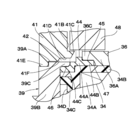
- FIG. 5 is an enlarged cross-sectional view showing a damping force adjusting valve and a solenoid in FIG. 1.
- FIG. 5 is an enlarged cross-sectional view showing a solenoid with the damping force adjusting valve in FIG. 2 removed.
- It is an enlarged view of the main part of the solenoid of FIG. 3 which shows the main part enlarged.
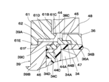
- It is an enlarged view of the main part of the solenoid by 2nd Embodiment.
- It is an enlarged view of the main part of the solenoid by the 3rd Embodiment.
- FIGS. 1 to 4 show the first embodiment.
- the damping force adjusting type hydraulic shock absorber 1 (hereinafter referred to as the hydraulic shock absorber 1) is provided with a solenoid 33 described later.
- the hydraulic shock absorber 1 includes an outer cylinder 2, an inner cylinder 4, a piston 5, a piston rod 8, a rod guide 9, a damping force adjusting mechanism 17, and the like.
- one side in the axial direction of the outer cylinder 2 and the inner cylinder 4 will be referred to as a lower side, a lower side or a lower end side, and the other side in the axial direction will be described as an upper side, an upper side or an upper end side.
- a lower side a lower side or a lower end side
- the other side in the axial direction will be described as an upper side, an upper side or an upper end side.
- the bottom end side of the bottomed cylindrical outer cylinder 2 forming the outer shell of the hydraulic shock absorber 1 is closed by the bottom cap 3, and the upper end side of the outer cylinder 2 is a crimped portion 2A bent inward in the radial direction. ..
- a rod guide 9 and a sealing member 10 are provided between the caulking portion 2A and the inner cylinder 4.
- an opening 2B is formed concentrically with the connection port 12C of the intermediate cylinder 12 described later, and a damping force adjusting mechanism 17 described later is attached to face the opening 2B.
- the bottom cap 3 is provided with a mounting eye 3A that is mounted on the wheel side of the vehicle, for example.
- an inner cylinder 4 is provided coaxially with the outer cylinder 2.
- the lower end side of the inner cylinder 4 is fitted and attached to the bottom valve 13, and the upper end side is fitted and attached to the rod guide 9.
- a working liquid as a working fluid is sealed in the inner cylinder 4 that constitutes the cylinder together with the outer cylinder 2.
- the working liquid is not limited to oil and oil, and may be, for example, water mixed with additives.
- An annular reservoir chamber A is formed between the inner cylinder 4 and the outer cylinder 2, and gas is sealed in the reservoir chamber A together with the working liquid.
- This gas may be air in an atmospheric pressure state, or a gas such as compressed nitrogen gas may be used.
- an oil hole 4A that allows the rod-side oil chamber B to always communicate with the annular oil chamber D is bored in the radial direction at an intermediate position in the length direction (axial direction) of the inner cylinder 4.
- the piston 5 is slidably inserted into the inner cylinder 4.
- the piston 5 defines the inside of the inner cylinder 4 into two chambers, a rod side chamber (rod side oil chamber B) and a bottom side chamber (bottom side oil chamber C).
- a plurality of oil passages 5A and 5B that enable communication between the rod-side oil chamber B and the bottom-side oil chamber C are formed in the piston 5 so as to be separated from each other in the circumferential direction.
- a disc valve 6 on the extension side is provided on the lower end surface of the piston 5.
- the extension-side disc valve 6 opens when the pressure in the rod-side oil chamber B exceeds the relief set pressure when the piston 5 slides and displaces upward in the extension stroke of the piston rod 8.
- the pressure is relieved to the bottom side oil chamber C side via each oil passage 5A.
- This relief set pressure is set to a pressure higher than the valve opening pressure when the damping force adjusting mechanism 17, which will be described later, is set hard.
- the upper end surface of the piston 5 is provided with a contraction side check valve 7 that opens when the piston 5 slides and displaces downward in the contraction stroke of the piston rod 8 and closes at other times.
- the check valve 7 allows the oil liquid in the bottom side oil chamber C to flow in each oil passage 5B toward the rod side oil chamber B, and prevents the oil liquid from flowing in the opposite direction. Is what you do.
- the valve opening pressure of the check valve 7 is set to a pressure lower than the valve opening pressure when the damping force adjusting mechanism 17 described later is softly set, and the check valve 7 does not substantially generate a damping force.
- the fact that this substantially no damping force is generated is a force equal to or less than the friction of the piston 5 and the seal member 10, and does not affect the movement of the vehicle.
- the piston rod 8 extends in the inner cylinder 4 in the axial direction (upward and downward).
- the lower end side of the piston rod 8 is inserted into the inner cylinder 4 and is fixed to the piston 5 by a nut 8A or the like. Further, the upper end side of the piston rod 8 projects so as to extend to the outside of the outer cylinder 2 and the inner cylinder 4 via the rod guide 9.
- a stepped cylindrical rod guide 9 is provided on the upper end side of the inner cylinder 4.
- the rod guide 9 positions the upper portion of the inner cylinder 4 at the center of the outer cylinder 2 and guides the piston rod 8 so as to be slidable in the axial direction on the inner peripheral side thereof.
- an annular seal member 10 is provided between the rod guide 9 and the crimped portion 2A of the outer cylinder 2.
- the seal member 10 is formed by baking an elastic material such as rubber on an annular metal plate through which the piston rod 8 is inserted in the center, and the inner circumference of the seal member 10 is in sliding contact with the outer peripheral surface of the piston rod 8 to be in contact with the piston rod 8. To seal.
- the seal member 10 is formed with a lip seal 10A as a check valve extending so as to come into contact with the rod guide 9 on the lower surface side.
- the lip seal 10A is arranged between the oil sump chamber 11 and the reservoir chamber A so that the oil liquid or the like in the oil sump chamber 11 flows toward the reservoir chamber A side through the return passage 9A of the rod guide 9. It forgives and blocks the reverse flow.
- An intermediate cylinder 12 made of a cylinder is arranged between the outer cylinder 2 and the inner cylinder 4.
- the intermediate cylinder 12 is attached to, for example, the outer peripheral side of the inner cylinder 4 via upper and lower tubular seals 12A and 12B.
- the intermediate cylinder 12 has an annular oil chamber D extending inside so as to surround the outer peripheral side of the inner cylinder 4 over the entire circumference, and the annular oil chamber D is an oil chamber independent of the reservoir chamber A.
- the annular oil chamber D is always in communication with the rod side oil chamber B by a radial oil hole 4A formed in the inner cylinder 4.
- the annular oil chamber D is a flow path in which the working liquid flows due to the movement of the piston rod 8.
- a connection port 12C to which the connection pipe body 20 of the damping force adjusting valve 18 described later is attached is provided on the lower end side of the intermediate cylinder 12.
- the bottom valve 13 is located on the lower end side of the inner cylinder 4 and is provided between the bottom cap 3 and the inner cylinder 4.
- the bottom valve 13 is a valve body 14 that defines a reservoir chamber A and a bottom side oil chamber C between the bottom cap 3 and the inner cylinder 4, and a disc valve on the reduction side provided on the lower surface side of the valve body 14. It is composed of 15 and an extension side check valve 16 provided on the upper surface side of the valve body 14.
- Oil passages 14A and 14B that allow communication between the reservoir chamber A and the bottom side oil chamber C are formed in the valve body 14 at intervals in the circumferential direction, respectively.
- the disc valve 15 on the reduction side opens when the pressure in the oil chamber C on the bottom side exceeds the relief set pressure when the piston 5 slides and displaces downward in the reduction stroke of the piston rod 8. Is relieved to the reservoir chamber A side via each oil passage 14A.
- This relief set pressure is set to a pressure higher than the valve opening pressure when the damping force adjusting mechanism 17, which will be described later, is set hard.
- the extension-side check valve 16 opens when the piston 5 slides and displaces upward during the extension stroke of the piston rod 8, and closes at other times.
- the extension-side check valve 16 allows the oil liquid in the reservoir chamber A to flow in each oil passage 14B toward the bottom-side oil chamber C, and prevents the oil liquid from flowing in the opposite direction. Is what you do.
- the valve opening pressure of the extension-side check valve 16 is set to a pressure lower than the valve opening pressure when the damping force adjusting mechanism 17, which will be described later, is softly set, and substantially no damping force is generated.
- the damping force adjusting mechanism 17 controls the flow of the working liquid generated by the sliding of the piston 5 in the cylinder (inner cylinder 4) to generate a damping force, and variably adjusts the generated damping force of the hydraulic shock absorber 1. It is a mechanism to do.
- the mover 48 actuating pin 49
- the coil 34A of the solenoid 33 for example, controlling to generate a hard damping force
- the damping force adjusting mechanism 17 is arranged so that its base end side (left end side in FIG. 1) is interposed between the reservoir chamber A and the annular oil chamber D, and the tip end side (FIG. 1).
- the right end side of the outer cylinder 2) is provided so as to project outward in the radial direction from the lower side of the outer cylinder 2.
- the damping force adjusting mechanism 17 includes a damping force adjusting valve 18 as a control valve that generates a damping force having hard or soft characteristics by variably controlling the flow of the oil liquid from the annular oil chamber D to the reservoir chamber A. It is configured to include a solenoid 33 described later that adjusts the operation of the on-off valve of the damping force adjusting valve 18.
- the valve opening pressure of the damping force adjusting valve 18 is adjusted by the solenoid 33 used as the damping force variable actuator, whereby the generated damping force is variably controlled to a hard or soft characteristic.
- the damping force adjusting valve 18 is a valve whose on-off valve operation is adjusted by a solenoid 33, and is between a flow path (for example, between the annular oil chamber D and the reservoir chamber A) where a flow of working liquid is generated by the movement of the piston rod 8. ).
- the damping force adjusting valve 18 has a substantially cylindrical valve case 19 provided so that the base end side thereof is fixed around the opening 2B of the outer cylinder 2 and the tip end side protrudes outward in the radial direction from the outer cylinder 2.
- the connection tube 20 is fixed to the connection port 12C of the intermediate cylinder 12 at the base end side, and the tip end side is an annular flange portion 20A, which is arranged inside the valve case 19 with a gap, and the connection tube body 20. It is configured to include a valve member 21 and the like that come into contact with the flange portion 20A.
- the base end side of the valve case 19 is an annular inner flange portion 19A extending inward in the radial direction, and the tip end side of the valve case 19 is the yoke 39 (one-side cylinder portion 39D) of the valve case 19 and the solenoid 33 described later. ) Is screwed into the lock nut 53, which is a male screw portion 19B.
- An annular oil that always communicates with the reservoir chamber A between the inner peripheral surface of the valve case 19 and the outer peripheral surface of the valve member 21, and further between the inner peripheral surface of the valve case 19 and the outer peripheral surface of the pilot body 26 or the like. Room 19C.
- an oil passage 20B that communicates with the annular oil chamber D and the other side extends to the position of the valve member 21.
- an annular spacer 22 is provided between the flange portion 20A of the connecting pipe body 20 and the inner flange portion 19A of the valve case 19 in a sandwiched state.
- the spacer 22 is provided with a plurality of notches 22A that serve as radial oil passages in order to communicate the oil chamber 19C and the reservoir chamber A.
- the spacer 22 is provided with a notch 22A for forming an oil passage.
- the inner flange portion 19A of the valve case 19 may be provided with notches for forming an oil passage in a radial pattern. In this configuration, the spacer 22 can be omitted to reduce the number of parts.
- the valve member 21 is provided with a central hole 21A located at the center in the radial direction and extending in the axial direction. Further, the valve member 21 is provided with a plurality of oil passages 21B spaced apart from each other in the circumferential direction around the central hole 21A, and one side (left side in FIG. 2) of each of these oil passages 21B is a connecting pipe body 20. It is always in communication with the oil passage 20B. Further, on the other end surface of the valve member 21 (right side in FIG. 2), an annular recess 21C formed so as to surround the other side opening of the oil passage 21B and a radially outer side of the annular recess 21C are located.
- each oil passage 21B of the valve member 21 is a main valve between the oil passage 20B of the connecting pipe body 20 communicating with the annular oil chamber D and the oil chamber 19C of the valve case 19 communicating with the reservoir chamber A. It becomes a flow path through which the pressure oil of the flow rate corresponding to the opening degree of 23 flows.
- the main valve 23 is composed of a disc valve whose inner peripheral side is sandwiched between the valve member 21 and the large diameter portion 24A of the pilot pin 24.
- the outer peripheral side of the main valve 23 is detached and seated on the annular valve seat 21D of the valve member 21.
- An elastic seal member 23A is fixed to the outer peripheral portion of the main valve 23 on the back surface side by means such as baking.
- the main valve 23 is opened by receiving pressure from the oil passage 21B side (annular oil chamber D side) of the valve member 21 and separating from the annular valve seat 21D.
- the oil passage 21B (annular oil chamber D side) of the valve member 21 is communicated with the oil chamber 19C (reservoir chamber A side) via the main valve 23, and the amount of pressure oil flowing in the arrow Y direction at this time. (Flow rate) is variably adjusted according to the opening degree of the main valve 23.
- the pilot pin 24 is formed in a stepped cylindrical shape, and an annular large diameter portion 24A is provided at an axially intermediate portion thereof.
- the pilot pin 24 has a central hole 24B extending in the axial direction on the inner peripheral side thereof, and a small diameter hole (orifice 24C) is formed at one end of the central hole 24B (the end on the connecting pipe body 20 side). ..
- One end side (left end side in FIG. 2) of the pilot pin 24 is press-fitted into the center hole 21A of the valve member 21, and the main valve 23 is sandwiched between the large diameter portion 24A and the valve member 21.
- the other end side (right end side in FIG. 2) of the pilot pin 24 is fitted in the center hole 26C of the pilot body 26.
- an oil passage 25 extending in the axial direction is formed between the center hole 26C of the pilot body 26 and the other end side of the pilot pin 24.
- the oil passage 25 communicates with a back pressure chamber 27 formed between the main valve 23 and the pilot body 26.
- a plurality of oil passages 25 extending in the axial direction are provided in the circumferential direction on the side surface on the other end side of the pilot pin 24, and the other circumferential positions are press-fitted into the central hole 26C of the pilot body 26.
- the pilot body 26 is formed as a substantially bottomed tubular body having a cylindrical portion 26A having a stepped hole formed inside and a bottom portion 26B that closes the cylindrical portion 26A.
- the bottom portion 26B of the pilot body 26 is provided with a central hole 26C into which the other end side of the pilot pin 24 is fitted.
- a protruding cylinder portion 26D extending to the valve member 21 side (that is, the left side in FIG. 2) is integrally provided over the entire circumference thereof.
- An elastic sealing member 23A of the main valve 23 is liquid-tightly fitted to the inner peripheral surface of the protruding cylinder portion 26D, whereby a back pressure chamber 27 is formed between the main valve 23 and the pilot body 26. ing.
- the back pressure chamber 27 generates a pressure (pilot pressure) that presses the main valve 23 in the valve closing direction, that is, in the direction in which the main valve 23 is seated on the annular valve seat 21D of the valve member 21.
- the bottom portion 26B of the pilot body 26 is provided with a valve seat portion 26E located on the other end side (right end side in FIG. 2) on which the pilot valve body 32 described later is taken off and seated so as to surround the central hole 26C. .. Further, inside the cylindrical portion 26A of the pilot body 26, a return spring 28 for urging the pilot valve body 32 in a direction away from the valve seat portion 26E of the pilot body 26, and a solenoid 33 described later are in a non-energized state (pilot).
- a disc valve 29 constituting a fail-safe valve (when the valve body 32 is farthest from the valve seat portion 26E), a holding plate 30 having an oil passage 30A formed on the center side, and the like are arranged.
- a cap 31 is fitted and fixed to the open end of the cylindrical portion 26A of the pilot body 26 with a return spring 28, a disc valve 29, a holding plate 30, and the like arranged inside the cylindrical portion 26A.
- Notches 31A are formed in the cap 31 at four positions separated in the circumferential direction, for example. These notches 31A serve as a flow path for flowing the oil liquid flowing toward the solenoid 33 side through the oil passage 30A of the holding plate 30 to the oil chamber 19C (reservoir chamber A side) in the direction of the arrow X shown in FIG. ing.
- the pilot valve body 32 constitutes a pilot valve together with the pilot body 26.
- the pilot valve body 32 is formed in a stepped cylindrical shape, and the tip portion for taking off and seating on the valve seat portion 26E of the pilot body 26 is a tapered portion.
- the operating pin 49 of the solenoid 33 which will be described later, is fixed inside the pilot valve body 32 in a fitted state, and the valve opening pressure of the pilot valve body 32 is adjusted according to the energization of the solenoid 33.
- a flange portion 32A serving as a spring receiver is formed on the base end side of the pilot valve body 32 over the entire circumference.
- the flange portion 32A contacts the inner peripheral portion of the disc valve 29 when the solenoid 33 is in a non-energized state (that is, when the pilot valve body 32 is displaced to the fully open position farthest from the valve seat portion 26E), and the pilot It regulates the maximum opening degree of the valve body 32.
- the solenoid 33 is used in a damping force adjusting shock absorber to adjust the on-off valve operation of the damping force adjusting valve 18. That is, the solenoid 33 used as the damping force variable actuator of the damping force adjusting mechanism 17 includes a mold coil 34, a storage member 36, a yoke 39, a stator 41, a non-magnetic ring 44, a mover 48, an operating pin 49, and a cover member 51. It is composed of.
- the mold coil 34 is formed in a substantially cylindrical shape by integrally covering (molding) the coil 34A with a resin member 34C such as a thermosetting resin in a state where the coil 34A is wound around the coil bobbin 34B. ..
- a cable take-out portion protruding outward in the axial direction or the radial direction is provided in a part of the mold coil 34 in the circumferential direction, and an electric wire cable (not shown) is connected to this cable take-out portion.
- the coil 34A is wound around the coil bobbin 34B in an annular shape, and becomes an electromagnet by supplying electric power (energization) through a cable from the outside to generate a magnetic force.
- a seal groove 34D is formed over the entire circumference on the side surface (end surface on one side in the axial direction) facing the yoke 39 (annular portion 39B) described later.
- a seal member (for example, an O-ring 35) is mounted in the seal groove 34D.
- the O-ring 35 tightly seals between the mold coil 34 and the yoke 39 (annular portion 39B). As a result, it is possible to prevent dust including rainwater and muddy water from entering the tubular protrusion 39C side of the yoke 39 via between the yoke 39 and the mold coil 34.
- the coil adopted in this embodiment is not limited to the molded coil 34 composed of the coil 34A, the coil bobbin 34B and the resin member 34C, and other coils may be adopted.
- the outer periphery of the coil is covered by an overmold (not shown) in which a resin material is molded from above (outer peripheral side). good.
- the storage member 36 constitutes a first fixed iron core (housing) arranged on the inner peripheral side of the mold coil 34 (that is, the inner circumference of the coil 34A).
- the storage member 36 is formed as a covered cylindrical cylinder by a magnetic material (magnetic material) such as low carbon steel or carbon steel for machine structure (S10C).
- the storage member 36 has a stepped storage cylinder portion 36A that extends in the winding axis direction of the mold coil 34 (coil 34A) and has one end open as a storage portion, and a stepped portion that closes the other end side of the storage cylinder portion 36A.
- the lid portion 36B and the small-diameter cylinder portion 36C for joining formed on the opening side (one side) of the storage cylinder portion 36A so as to reduce the diameter of the outer periphery thereof are included.
- a non-magnetic ring 44 which will be described later, is joined to the small diameter tubular portion 36C of the storage member 36 by a brazing portion 45.
- the inner diameter of the storage cylinder portion 36A of the storage member 36 is formed to be slightly larger than the outer diameter of the mover 48 described later, and the mover 48 is movably stored in the storage cylinder portion 36A in the axial direction. ing.
- the lid portion 36B (right side of FIGS. 2 and 3) of the storage member 36 is integrally formed with the storage cylinder portion 36A as a covered cylinder that closes the storage cylinder portion 36A from the other side in the axial direction.
- the outer diameter of the lid portion 36B has a stepped shape smaller than the outer diameter of the storage cylinder portion 36A, and the fitting cylinder portion 51A of the cover member 51 described later is fitted on the outer peripheral side of the lid portion 36B. It is provided.
- the storage member 36 is formed with a bottomed stepped hole 37 located inside the lid portion 36B.
- the stepped hole 37 is composed of a bush mounting hole 37A and a small diameter hole 37B located on the inner side of the bush mounting hole 37A and formed to have a small diameter.
- a first bush 38 for slidably supporting the operation pin 49 described later is provided in the bush mounting hole portion 37A.
- the lid portion 36B of the storage member 36 is arranged so that the other side end faces face the lid plate 51B of the cover member 51, which will be described later, with a gap in the axial direction.
- This axial gap has a function of preventing an axial force from being directly applied to the storage member 36 from the lid plate 51B side of the cover member 51 via the lid portion 36B.
- the lid portion 36B of the storage member 36 does not necessarily have to be integrally formed of the same material (magnetic material) as the storage cylinder portion 36A.
- the lid portion 36B can be formed of, for example, a rigid metal material, a ceramic material, or a fiber-reinforced resin material, instead of the magnetic material.
- the yoke 39 is a magnetic member that forms a magnetic circuit (magnetic path) together with the storage member 36 over the inner peripheral side and the outer peripheral side of the mold coil 34 (coil 34A).
- the yoke 39 is formed by using a magnetic material (magnetic material) like the storage member 36, and extends in the radial direction on one side in the axial direction (one side in the winding axis direction) of the mold coil 34 (coil 34A).
- An annular portion 39B whose inner peripheral side is a stepped fixing hole 39A and an annular portion 39B from the inner peripheral side to the other side in the axial direction (connecting member 44 described later) along the axial direction of the fixing hole 39A. It is configured to include a tubular protrusion 39C for joining that protrudes in a tubular shape.
- the yoke 39 has a cylindrical one-sided tubular portion 39D extending from the outer peripheral side of the annular portion 39B toward one side in the axial direction (damping force adjusting valve 18 side), and an axial direction and the like from the outer peripheral side of the annular portion 39B.
- the other side cylinder 39E extending toward the side (cover member 51 side) and surrounding the mold coil 34 from the outside in the radial direction, and the cover member 51 provided on the tip end side of the other side cylinder 39E. It is formed as an integral body including a caulking portion 39F that holds the flange portion 51C in a retaining state.
- the other side cylinder portion 39E of the yoke 39 is provided with a notch (not shown) for exposing the cable extraction portion of the mold coil 34 described above to the outside of the other side cylinder portion 39E.
- an engaging recess 39G having a semicircular cross section so as to open to the outer peripheral surface of the yoke 39 is provided (over the entire circumference or in the circumferential direction). It is provided in multiple places) apart from each other.
- a lock nut 53 which will be described later, screwed to the valve case 19 of the damping force adjusting valve 18 is engaged with the engaging recess 39G via a retaining ring 54 (see FIG. 2).
- a seal groove 39H is provided on the outer peripheral surface of the one-side cylinder portion 39D over the entire circumference.
- An O-ring 40 as a sealing member is mounted on the seal groove 39H, and the O-ring 40 tightly seals the yoke 39 (one side cylinder 39D) and the valve case 19 of the damping force adjusting valve 18. It has been stopped.
- the stator 41 is a second fixing iron core (anchor) fixed in the fixing hole 39A of the yoke 39 by means such as press fitting.
- the stator 41 is made of a magnetic material (magnetic material) such as a storage member 36 (first fixed iron core), low carbon steel like the yoke 39, and carbon steel for machine structure (S10C) to form a fixing hole 39A of the yoke 39. It is formed in a shape that fills from the inside.
- the stator 41 is formed as a short cylindrical annular body having a through hole 41A whose central side extends in the axial direction.
- One side surface of the stator 41 in the axial direction (the surface facing the cap 31 of the damping force adjusting valve 18 shown in FIG. 2 in the axial direction) is formed so as to be a flat surface like one side surface of the annular portion 39B of the yoke 39. Has been done.
- a circular recess 41B is recessed so as to be coaxial with the storage cylinder portion 36A.
- the recessed portion 41B is formed as a circular groove having a diameter slightly larger than that of the mover 48 so that the mover 48, which will be described later, can be inserted into and out of the recessed portion 41B by magnetic force.
- a conical protrusion 41C is provided so as to surround the periphery (outer circumference) of the recessed portion 41B.
- the outer peripheral surface of the conical protrusion 41C is formed as a conical surface so that the magnetic characteristic is linear between the stator 41 and the mover 48.
- the conical protrusion 41C projects in a cylindrical shape from the outer peripheral side of the stator 41 toward the other side in the axial direction, and the outer peripheral surface thereof is recessed from one side in the axial direction to the other side (the recesses shown in FIGS. 3 and 4).
- the conical surface is tapered in a tapered shape so that the outer diameter dimension gradually decreases from the outer side to the inner side in the radial direction of the portion 41B.
- the conical protrusion 41C of the stator 41 is provided at a position facing the opening of the storage member 36 (storage cylinder 36A), and the outer diameter is reduced as it approaches the opening of the storage cylinder 36A. It is a department.
- a side surface portion 41D extending in a direction away from the opening of the storage cylinder portion 36A is formed along the outer circumference of the conical protrusion 41C (diameter-reduced portion).
- one side portion in the axial direction of the stator 41 is an annular flange portion 41E protruding outward in the radial direction, and a conical protrusion 41C (contraction) is formed in the intermediate portion in the axial direction of the side surface portion 41D.
- the step portion 41F is integrally formed so as to be located between the diameter portion) and the flange portion 41E.
- the annular flange portion 41E is arranged at a position largely separated from the opening end of the storage cylinder portion 36A on one side in the axial direction (that is, the end of the anti-storage portion of the stator 41), and is inside the fixing hole 39A of the yoke 39. It is fixed to the flange by means such as press fitting.
- the annular flange portion 41E serves as a fixing portion of the stator 41 (side surface portion 41D) with respect to the fixing hole 39A of the yoke 39, and is also a portion where the flange portion 41E and the fixing hole 39A face each other in the radial direction.
- a non-contact portion located on the other side (storage member 36 side) of the flange portion 41E in the axial direction and in contact with each other. 42 is formed.
- the non-contact portion 42 is formed by an annular gap formed over the entire circumference between the fixing hole 39A of the yoke 39 and the side surface portion 41D (step portion 41F) of the stator 41.
- the step portion 41F is formed on a surface facing the side surface portion 41D of the stator 41 and the yoke 39 (fixing hole 39A) in the radial direction.
- the step portion 41F is formed on the reduced diameter portion (conical protrusion 41C) side of the side surface portion 41D.
- a second bush 43 for slidably supporting the operation pin 49 described later in the stepped through hole 41A formed on the center (inner circumference) side of the stator 41. are fitted together.
- a pilot body 26 of the damping force adjusting valve 18, a return spring 28, a disc valve 29, a holding plate 30, a cap 31, and the like are provided on the inner peripheral side of the one-side cylinder portion 39D of the yoke 39. It is provided by inserting it. Further, the valve case 19 of the damping force adjusting valve 18 is fitted (outerly fitted) on the outer peripheral side of the one-side cylinder portion 39D.
- the non-magnetic ring 44 is a non-magnetic connecting member provided on the inner peripheral side of the mold coil 34 (coil 34A) located between the small diameter tubular portion 36C of the storage member 36 and the tubular protrusion 39C of the yoke 39. (Cylinder).
- the non-magnetic ring 44 is formed as a stepped cylinder by a non-magnetic material such as austenitic stainless steel.
- the non-magnetic ring 44 is composed of a stepped cylinder portion 44A in the middle in the axial direction and first and second connecting cylinder portions 44B and 44C protruding in the axial direction from both ends of the stepped cylinder portion 44A, respectively. ..
- the non-magnetic ring 44 is formed in the second connecting cylinder portion 44C in a radial dimension larger than that of the first connecting cylinder portion 44B by, for example, the thickness of the connecting cylinder portion 44B. Then, the first and second connecting cylinder portions 44B and 44C are molded together with the stepped cylinder portion 44A with a required wall thickness (thickness in the radial direction) by the non-magnetic material so as to secure a desired coaxiality. There is.
- the first connecting cylinder portion 44B of the non-magnetic ring 44 is fitted to the small diameter cylinder portion 36C of the storage member 36 from the outside, and both are joined by a brazing portion 45. Further, the second connecting cylinder portion 44C is fitted to the outer peripheral side of the tubular protrusion portion 39C of the yoke 39, and the two are joined by the brazing portion 46.
- the brazing portions 45 and 46 are each made of a brazing material made of pure copper brazing, and by performing a brazing treatment of, for example, 1000 ° C. or higher, the non-magnetic ring 44 is housed in the small diameter cylinder portion 36C of the storage member 36 and the cylinder of the yoke 39. It is joined to the shape protrusion 39C. After the brazing process, a quenching process is performed. In this state, the inner diameter of the non-magnetic ring 44 (that is, the inner diameter of the stepped cylinder portion 44A) is larger than the inner diameter of the storage member 36 (storage cylinder portion 36A) and is larger than the inner diameter of the stator 41, as shown in FIG. It is formed so as to be larger than the recessed portion 41B (that is, the radial dimension of the recessed portion 41B).
- the small-diameter tubular portion 36C of the storage member 36 is formed with an annular gap 47 on the outer peripheral side thereof from the first connecting tubular portion 44B of the non-magnetic ring 44.
- the gap 47 is an introduction path for pouring the brazing material (pure copper wax) between the storage member 36 (small diameter cylinder portion 36C) and the non-magnetic ring 44 (first connecting cylinder portion 44B) in a heat-melted state. be.
- the gap 47 also functions as a gap for absorbing the difference in thermal expansion between the small-diameter tubular portion 36C of the storage member 36 (cylindrical protrusion 39C of the yoke 39) and the non-magnetic ring 44.
- the brazing material (pure copper brazing) of the brazing portion 46 is also poured between the tubular protrusion 39C of the yoke 39 and the non-magnetic ring 44 (second connecting cylinder 44C) in a heat-melted state.
- the introduction path is formed in the same manner as the gap 47.
- the brazing material pure copper brazing
- the brazing material is poured into the non-magnetic ring 44 in order to join the second connecting cylinder portion 44C to the outer peripheral surface of the tubular protrusion portion 39C of the yoke 39, the non-magnetic ring 44 is between the two.
- An axial external force is applied to the gap to eliminate the gap as much as possible.
- the non-magnetic ring 44 is a non-magnetic connecting member made of austenitic stainless steel, and when the non-magnetic ring 44 is joined between the storage member 36 and the yoke 39 by brazing portions 45 and 46, Brazing is performed using pure copper brazing material.
- the material when distortion occurs due to deep drawing or cutting of austenitic stainless steel parts, which are non-magnetic materials, the material produces work-induced martensite, and some crystal structures are ideal surfaces as non-magnetic materials. It transforms into a body-centered cubic structure instead of a face-centered cubic structure, resulting in the property that the non-magnetic material is easily magnetized.
- the work-induced martensite of the austenitic stainless steel is removed by heat treatment at 1000 ° C. or higher, and the structure returns to the ideal face-centered cubic structure again. This process is called solution heat treatment.
- pure copper brazing material is selected as the brazing material having a brazing temperature of 1000 ° C. or higher, and the brazing portions 45 and 46 perform a treatment that combines brazing and solidification heat treatment to form the storage member 36.
- the non-magnetic ring 44 joined between the small-diameter tubular portion 36C and the tubular protrusion 39C of the yoke 39 can return the crystal structure to an ideal face-centered cubic structure as a non-magnetic material.
- the brazing material may be other than pure copper brazing as long as the brazing temperature is 1000 ° C. or higher.
- brass brazing, nickel brazing, gold brazing, palladium brazing and the like may be used.
- the non-magnetic ring 44 is joined between the small-diameter tubular portion 36C of the storage member 36 and the tubular protrusion 39C of the yoke 39 via brazing portions 45 and 46, and is rapidly cooled after brazing. Even if a difference in thermal expansion occurs due to a difference in the material (material) between the two, the generation of strain based on this can be suppressed by the gap 47.
- the connecting member made of a non-magnetic material is a means other than brazing (for example, a laser) between the small diameter tubular portion 36C of the storage member 36 and the tubular protrusion 39C of the yoke 39. It may be configured to be joined by heating by a joining means such as welding).
- the movable armature 48 is an armature made of a magnetic material provided so as to be movable in the winding axis direction of the coil 34A between the storage cylinder portion 36A of the storage member 36 and the concave recess portion 41B of the stator 41.
- the mover 48 is arranged on the inner peripheral side of the storage cylinder portion 36A of the storage member 36, the concave recess portion 41B of the stator 41, the tubular protrusion portion 39C of the yoke 39, and the non-magnetic ring 44, and is arranged on the inner peripheral side of the storage cylinder of the storage member 36. It is movable in the axial direction between the portion 36A and the recessed portion 41B of the stator 41.
- the mover 48 is arranged on the inner peripheral side of the storage cylinder portion 36A of the storage member 36 and the recessed portion 41B of the stator 41, and the first and second bushes 38, 43 and the magnetic force generated in the coil 34A are generated. It is movable in the axial direction via the actuating pin 49.
- the mover 48 is fixed (integrated) to an actuating pin 49 extending through the center side thereof, and moves together with the actuating pin 49.
- the actuating pin 49 is slidably supported in the axial direction by the lid portion 36B of the storage member 36 and the stator 41 via the first and second bushes 38 and 43.
- the mover 48 is formed in a substantially cylindrical shape using an iron-based magnetic material, like the storage member 36, the yoke 39, and the stator 41, for example. Then, the magnetic force generated in the coil 34A of the mover 48 generates a thrust in the direction of being attracted to the recessed portion 41B of the stator 41.
- the operating pin 49 is a shaft portion that transmits the thrust of the mover 48 to the pilot valve body 32 of the damping force adjusting valve 18 (control valve), and is formed by a hollow rod.
- a mover 48 is integrally fixed to the axially intermediate portion of the actuating pin 49 by means such as press fitting, whereby the mover 48 and the actuating pin 49 are subassembled. Both sides of the operating pin 49 in the axial direction are slidably supported by the lid portion 36B on the storage member 36 side and the yoke 39 (stator 41) via the first and second bushes 38 and 43.
- the mover 48 is configured to open and close the pilot valve of the hydraulic shock absorber 1 (that is, the pilot valve body 32 with respect to the pilot body 26) by moving in the axial direction by the magnetic force from the coil 34A.
- the back pressure chamber 50 is an oil chamber formed between the lid portion 36B of the storage member 36 (small diameter hole portion 37B of the stepped hole 37) and the other end of the operating pin 49 (right end portion in FIG. 2). ..
- the back pressure chamber 50 communicates with the center hole 24B side of the pilot pin 24 via a hollow rod (actuating pin 49). Therefore, the same pressure as the pilot valve body 32 that takes off and seats on the valve seat portion 26E of the pilot body 26 acts on the back pressure chamber 50.
- the area where the other end surface of the operating pin 49 receives the pressure in the back pressure chamber 50 is such that the pilot valve body 32 (one end side of the operating pin 49) is between the valve seat portion 26E. It is smaller than the area to receive pressure.
- the thrust to be transmitted from the mover 48 to the pilot valve body 32 of the damping force adjusting valve 18 via the actuating pin 49 can be reduced by the difference in the pressure receiving area between the two.
- the pilot valve body 32 of the damping force adjusting valve 18 is formed from the mover 48 via the actuating pin 49.
- the thrust to be transmitted (for example, the magnetic force to be generated by the coil 34A of the mold coil 34) can be reduced, and the entire solenoid 33 can be made smaller and lighter.
- the cover member 51 is a magnetic cover that covers the mold coil 34 from the outside together with the other side cylinder portion 39E of the yoke 39.
- the cover member 51 is formed of a magnetic material (magnetic material) as a lid that covers the mold coil 34 from the other side in the axial direction, and is a magnetic circuit outside the mold coil 34 (coil 34A) together with the other side cylinder portion 39E of the yoke 39. (Magnetic path) is formed.
- the cover member 51 is formed in a covered tubular shape as a whole, and has a cylindrical fitting cylinder portion 51A and the other end side (right end portion in FIGS. 2 and 3) of the fitting cylinder portion 51A. It is roughly composed of a dish-shaped lid plate 51B that closes.
- the fitting cylinder portion 51A of the cover member 51 is inserted into the outer periphery of the lid portion 36B of the storage member 36, and in this state, the lid portion 36B of the storage member 36 is accommodated inside.
- the outer peripheral side of the cover plate 51B of the cover member 51 is an annular flange portion 51C extending radially outward of the fitting cylinder portion 51A, and the outer peripheral edge of the flange portion 51C is the other side cylinder portion 39E of the yoke 39. It is fixed to the caulking portion 39F provided in.
- the other side cylinder portion 39E of the yoke 39 and the lid plate 51B of the cover member 51 are pre-assembled (sub-assembled) with the mold coil 34 incorporated inside as shown in FIG.
- the lid portion 36B of the storage member 36 is the fitting cylinder portion 51A of the cover member 51. It is fitted inside. As a result, the magnetic flux can be transferred between the fitting cylinder portion 51A of the cover member 51, the lid plate 51B, and the yoke 39. Further, in the fitting cylinder portion 51A of the cover member 51, a seal groove 51D is formed over the entire circumference on the outer peripheral side where the resin member 34C of the mold coil 34 is fitted. A seal member (for example, an O-ring 52) is mounted in the seal groove 51D.
- a seal member for example, an O-ring 52
- the O-ring 52 tightly seals between the mold coil 34 and the cover member 51 (fitting cylinder portion 51A). As a result, dust containing rainwater and muddy water invades between the storage member 36 and the mold coil 34, further between the storage member 36 and the cover member 51, etc. via the cover member 51 and the mold coil 34. You can prevent it from happening.
- the yoke 39 and the cover member 51 have a molded coil 34 built therein, and as shown in FIG. 2, a damping force is applied by using a locknut 53 as a fastening member and a retaining ring 54. It is fastened to the valve case 19 of the adjusting valve 18.
- the retaining ring 54 is attached to the engaging recess 39G of the yoke 39 prior to the locknut 53.
- the retaining ring 54 partially protrudes outward in the radial direction from the engaging recess 39G of the yoke 39, and transmits the fastening force of the locknut 53 to the one-side cylinder portion 39D of the yoke 39.
- the locknut 53 is formed as a stepped tubular body, and has a female screw portion 53A that is located on one side in the axial direction and is screwed into the male screw portion 19B of the valve case 19 on the inner peripheral side, and a retaining ring 54 having an inner diameter.
- An engaging cylinder portion 53B that is bent inward in the radial direction so as to be smaller than the outer diameter dimension and engages with the retaining ring 54 from the outside is provided.
- the locknut 53 has a female screw portion 53A and a male screw portion 19B of the valve case 19 in a state where the inner side surface of the engagement cylinder portion 53B is in contact with the retaining ring 54 mounted on the engagement recess 39G of the yoke 39. It is a fastening member that integrally connects the damping force adjusting valve 18 and the solenoid 33 by screwing and.
- the solenoid 33, the damping force adjusting mechanism 17, and the hydraulic shock absorber 1 according to the first embodiment have the above-described configurations, and the operation thereof will be described next.
- the hydraulic shock absorber 1 is mounted on a vehicle such as an automobile, for example, the protruding end (upper end) side of the piston rod 8 is mounted on the vehicle body side, and the mounting eye 3A side provided on the bottom cap 3 is mounted on the wheel side. Be done. Then, the solenoid 33 of the damping force adjusting mechanism 17 is connected to a control device (controller) provided on the vehicle body side of the vehicle via an electric wiring cable (none of which is shown) or the like.
- a control device controller
- the controller variably controls the generated damping force of the hydraulic shock absorber 1 by changing the current value of the control signal energizing the coil 34A of the solenoid 33 and adjusting the valve opening pressure of the pilot valve body 32. can do.
- the magnetic force (magnetic flux) generated by the coil 34A of the solenoid 33 passes through the mover 48 side so as to avoid the non-magnetic ring 44 (non-magnetic connecting member) from the storage member 36, and from the mover 48 to the stator 41.
- the yoke 39 reaches the fixing hole 39A, the annular portion 39B, and the other side tubular portion 39E, and further, the cover member 51 from the caulking portion 39F side of the yoke 39.
- the magnetic circuit is configured so as to pass through the lid plate 51B and the fitting cylinder portion 51A and return to the storage cylinder portion 36A of the storage member 36.
- the magnetic circuit is a magnetic flux between the movable element 48 and the accommodating member 36 which face each other through a minute gap, and also between the movable element 48 and the conical protrusion 41C (reduced diameter portion) of the stator 41. Except for the transfer, the magnetic flux can be transferred by the contact portion (that is, the portion where the magnetic materials are in surface contact with each other). Therefore, the magnetic circuit of the solenoid 33 can secure high magnetic efficiency.
- the mold coil 34 (coil 34A) ) Is provided on the inner peripheral side of the non-magnetic ring 44, which is a non-magnetic connecting member.
- the non-magnetic ring 44 is joined by brazing portions 45 and 46 between the small diameter tubular portion 36C of the storage member 36 and the tubular protrusion 39C of the yoke 39 so as to increase the magnetic flux density of the magnetic circuit with respect to the mover 48. Has been done.
- the non-magnetic connecting member (non-magnetic ring 44) is machined after joining (for example, the inner peripheral surface is machined)
- the magnetic characteristics change due to the machining strain at this time
- the non-magnetic connecting member (non-magnetic ring 44) is non-magnetic.
- the connecting member is easily magnetized.
- the non-magnetic ring 44 made of a non-magnetic material such as austenitic stainless steel is projected axially from both ends of the stepped cylinder portion 44A in the middle in the axial direction and the stepped cylinder portion 44A. It is formed as a stepped cylindrical integral body by the first and second connecting cylinder portions 44B and 44C.
- the inner diameter of the non-magnetic ring 44 (stepped cylinder 44A) is formed to be larger than the inner diameter of the small diameter cylinder 36C of the storage member 36 and the tubular protrusion 39C of the yoke 39.
- the inner diameter of the non-magnetic ring 44 (that is, the inner diameter dimension of the stepped cylinder portion 44A) is determined. As shown in FIGS. 3 and 4, the inner diameter of the storage member 36 (storage cylinder portion 36A) is larger than the inner diameter of the yoke 39 (that is, the inner diameter of the fixing hole 39A and the tubular protrusion 39C). Has been done.
- the diameter dimension of the recessed portion 41B of the stator 41, the inner diameter dimension of the conical protrusion 41C (reduced diameter portion), and the inner diameter dimension of the non-magnetic ring 44 are further increased. Is configured to be large.
- a stator 41 is provided in the fixing hole 39A of the yoke 39 so as to be coaxial with the storage cylinder portion 36A of the storage member 36 with the mover 48 interposed therebetween in the axial direction.
- a reduced diameter portion (conical protrusion 41C) whose outer diameter decreases as it approaches the opening of the storage cylinder portion 36A, and a side surface portion 41D extending from the outer circumference of the reduced diameter portion in a direction away from the opening of the storage cylinder portion 36A.
- An annular flange portion 41E protruding outward in the radial direction is provided on one side portion of the side surface portion 41D in the axial direction of the stator 41, and a conical protrusion is provided in the middle portion in the axial direction of the side surface portion 41D.
- the step portion 41F is integrally formed so as to be located between the portion 41C (reduced diameter portion) and the flange portion 41E.
- the flange portion 41E of the stator 41 is arranged at a position largely separated from the opening end of the storage cylinder portion 36A on one side in the axial direction (that is, the end of the anti-storage portion of the stator 41), and fixes the yoke 39. It is fixed in the hole 39A by means such as press fitting.
- the flange portion 41E of the stator 41 is a fixing portion of the stator 41 (side surface portion 41D) with respect to the fixing hole 39A of the yoke 39, and is also a portion where the flange portion 41E and the fixing hole 39A face each other in the radial direction.
- the yoke 39 has a fixing hole 39A in which a part (flange portion 41E) of the side surface portion 41D of the stator 41 is fixed to the inner peripheral surface, and the stator is provided on the storage member 36 side of the fixing hole 39A.
- a non-contact portion 42 that is non-contact with the side surface portion 41D of 41 is formed.
- the mover 48 can be arranged so as to be movable in the axial direction by being located on the inner peripheral side of the magnetic connecting member).
- the non-magnetic ring 44 is provided with a machine after joining the small-diameter tubular portion 36C of the storage member 36 and the tubular protrusion 39C of the yoke 39. It is not necessary to perform processing (for example, cutting the inner peripheral surface), and the magnetic characteristics of the non-magnetic ring 44 do not change due to thermal influence, processing strain, or the like.
- the non-magnetic ring 44 is joined between the storage member 36 and the yoke 39 by the brazing portions 45 and 46, and then the flange portion 41E of the stator 41 is press-fitted into the fixing hole 39A of the yoke 39 to fix it.
- a non-contact portion 42 is formed between the fixing hole 39A of the yoke 39 and the side surface portion 41D of the stator 41. Therefore, even if a part of the brazing material (pure copper brazing) formed by the brazing parts 45 and 46 exists between the tubular protrusion 39C and the connecting cylinder portion 44C of the non-magnetic ring 44, this brazing material is present.
- the press-fitting (fixing) work of the stator 41 is not adversely affected, and the conical protrusion 41C (reduced diameter portion) of the stator 41 is deformed inward in the radial direction by an external force at the time of press-fitting. It can be suppressed.
- the press-fitting work of the stator 41 which is performed after the non-magnetic ring 44 is joined between the storage member 36 and the yoke 39 by the brazing portions 45 and 46, can be smoothly performed. That is, the work of press-fitting the flange portion 41E of the stator 41 into the fixing hole 39A of the yoke 39 to fix it can be smoothly performed.
- the magnetic circuit of the solenoid 33 is different from the transfer of magnetic flux between the mover 48 and the storage member 36 facing each other through a minute gap, and also between the mover 48 and the conical protrusion 41C of the stator 41. Since the magnetic flux can be transferred in a state where all the magnetic materials are in surface contact with each other, the magnetic circuit of the solenoid 33 can secure high magnetic efficiency.
- first connecting cylinder portion 44B of the non-magnetic ring 44 is fitted to the small diameter cylinder portion 36C of the storage member 36 from the outside, and both are joined by the brazing portion 45.
- second connecting cylinder portion 44C is fitted to the outer peripheral side of the tubular protrusion portion 39C of the yoke 39, and both are joined by a brazing portion 46.
- the brazing portions 45 and 46 are each subjected to a brazing treatment of 1000 ° C. or higher using a brazing material made of pure copper brazing, so that the non-magnetic ring 44 can be stored in the small diameter cylinder portion 36C and the yoke 39 of the storage member 36. It is joined to the cylindrical protrusion 39C of the above, and a quenching treatment is performed after the brazing treatment.
- the small-diameter tubular portion 36C of the storage member 36, the tubular protrusion 39C of the yoke 39, and the non-magnetic ring 44 are configured as described above, and the brazed portions 45 and 46 are made of pure copper brazing (wax).
- the brazed portions 45 and 46 are made of pure copper brazing (wax).
- stator 41 that is, the stator 41 in the fixing hole 39A of the yoke 39
- the press-fitting operation of the stator 41 is performed after the non-magnetic ring 44 is joined between the storage member 36 and the yoke 39 by the brazing portions 45 and 46.
- the work of press-fitting and fixing the flange portion 41E) can be smoothly performed.
- the axial length of the damping force adjusting mechanism 17 (solenoid 33) is shortened. Therefore, even when the axial length of the solenoid 48 is shortened, the storage area of the mold coil 34 (coil 34A) is not reduced by increasing the outer diameter of the solenoid 48, so that the number of coil turns and the resistance value can be adjusted. There is no effect, and the thrust characteristics of the solenoid 33 can be secured.
- the non-magnetic ring 44 is brazed between the storage member 36 and the yoke 39, and then the stator 41 is smoothly press-fitted (fixed) into the fixing hole 39A of the yoke 39. This can be done, and it is possible to prevent the conical protrusion 41C (reduced diameter portion) of the stator 41 from being deformed inward in the radial direction due to an external force at the time of press fitting.
- the magnetic flux density passing through the mover 48 can be maintained high between the storage member 36 and the stator 41 (yoke 39), and the thrust characteristics of the solenoid 33 can be kept good.
- workability during assembly can be improved.
- a connecting member 44 made of a non-magnetic material to be heated and joined between the storage member 36 and the yoke 39 is provided, but the space between the storage member 36 and the yoke 39 is press-fitted. Since the same problem arises even when the seal is sealed with the above, the present invention can be carried out.
- FIG. 5 shows a second embodiment, and in the present embodiment, the same components as those in the first embodiment described above are designated by the same reference numerals, and the description thereof will be omitted.
- a feature of the second embodiment is that the stator 61 is press-fitted into the fixing hole 39A of the yoke 39 to fix the stator 61 in place of the stator 41 of the first embodiment.
- the stator 61 adopted in the second embodiment is formed of a magnetic material (magnetic material) in the same manner as the stator 41 described in the first embodiment so as to fill the fixing hole 39A of the yoke 39 from the inside. ing.
- the stator 61 is formed as a short cylindrical annular body having a through hole (not shown) extending in the central side in the axial direction, and has a circular recessed portion 61B. It has a conical protrusion 61C (reduced diameter portion) and a side surface portion 61D.
- An annular flange portion 61E projecting outward in the radial direction is integrally formed on one side portion of the side surface portion 61D in the axial direction of the stator 61.
- the stator 61 adopted in the second embodiment has a side surface portion 61D composed of a flange portion 61E and a cylindrical portion 61F.
- the cylindrical portion 61F of the stator 61 is formed in a flat cylindrical shape along the outer circumference of the conical protrusion 61C (diameter-reduced portion) up to the position of the flange portion 61E.
- a non-contact portion located on the other side (storage member 36 side) in the axial direction from the flange portion 61E and in contact with each other. 62 is formed.
- the non-contact portion 62 is composed of an annular gap formed over the entire circumference between the fixing hole 39A of the yoke 39 and the cylindrical portion 61F of the stator 61.
- a non-contact portion 62 formed of an annular gap over the entire circumference is formed between the cylindrical portion 61F of the stator 61 and the fixing hole 39A of the yoke 39. Therefore, at the time of assembling the solenoid 33, the non-magnetic ring 44 is brazed between the storage member 36 and the yoke 39, and then the stator 61 is smoothly press-fitted (fixed) into the fixing hole 39A of the yoke 39. It is possible to prevent the conical protrusion 61C (reduced diameter portion) of the stator 61 from being deformed inward in the radial direction due to an external force at the time of press fitting.
- FIG. 6 shows a third embodiment, and in the present embodiment, the same components as those in the first embodiment described above are designated by the same reference numerals, and the description thereof will be omitted.
- a feature of the third embodiment is that the stator 71 is press-fitted into the fixing hole 39A of the yoke 39 to fix the stator 71 instead of the stator 41 of the first embodiment.
- the stator 71 adopted in the third embodiment is formed of a magnetic material (magnetic material) in the same manner as the stator 41 described in the first embodiment so as to fill the fixing hole 39A of the yoke 39 from the inside. ing. Similar to the stator 41 of the first embodiment, the stator 71 has a through hole on the center side (not shown), a circular recessed portion 71B, a conical protrusion 71C (diameter-reduced portion), and a side surface portion 71D. have. An annular flange portion 71E projecting outward in the radial direction is integrally formed on one side portion of the side surface portion 71D in the axial direction of the stator 71.
- the stator 71 adopted in the third embodiment has a side surface portion 71D composed of a flange portion 71E and an inclined cylinder portion 71F.
- the inclined tubular portion 71F of the stator 71 is formed in a tapered shape that is obliquely inclined to the position of the flange portion 71E along the outer circumference of the conical protrusion 71C (diameter-reduced portion). Then, between the inclined tubular portion 71F of the stator 71 and the fixing hole 39A of the yoke 39, they are located on the other side (storage member 36 side) in the axial direction from the flange portion 71E and are not in contact with each other.
- a portion 72 is formed.
- the non-contact portion 72 is formed by an annular gap having a V-shaped cross section formed over the entire circumference between the fixing hole 39A of the yoke 39 and the inclined tubular portion 71F of the stator 71.
- the non-contact portion 72 formed of an annular gap having a V-shaped cross section over the entire circumference is formed between the inclined tubular portion 71F of the stator 71 and the fixing hole 39A of the yoke 39. It is formed. Therefore, at the time of assembling the solenoid 33, after the non-magnetic ring 44 is brazed between the storage member 36 and the yoke 39, the stator 71 is smoothly press-fitted into the fixing hole 39A of the yoke 39. It is possible to prevent the conical protrusion 71C (reduced diameter portion) of the stator 71 from being deformed inward in the radial direction due to an external force at the time of press fitting.
- FIG. 7 shows a fourth embodiment, and in the present embodiment, the same components as those in the first embodiment described above are designated by the same reference numerals, and the description thereof will be omitted.
- a feature of the fourth embodiment is that the stator 81 is press-fitted into the fixing hole 39A of the yoke 39 to fix the stator 81 instead of the stator 41 of the first embodiment.
- the stator 81 adopted in the fourth embodiment is formed of a magnetic material (magnetic material) in the same manner as the stator 41 described in the first embodiment so as to fill the fixing hole 39A of the yoke 39 from the inside. ing.
- the stator 81 has a through hole (not shown) on the center side, a circular recess 81B, a conical protrusion 81C (diameter-reduced portion), and a side surface portion, substantially similar to the stator 41 of the first embodiment. It has 81D.
- An annular flange portion 81E projecting outward in the radial direction is integrally formed on one side portion of the side surface portion 81D in the axial direction of the stator 81.
- the stator 81 adopted in the fourth embodiment is formed as an arc tapered surface 81F in which the conical protrusion 81C (reduced diameter portion) and the side surface portion 81D are obliquely inclined in an arc shape to the position of the flange portion 81E.
- the arc tapered surface 81F is an arc surface that is obliquely inclined from the conical protrusion 81C (reduced diameter portion) of the stator 81 to the position of the flange portion 81E, and the conical protrusion 81C and the side surface 81D.
- the space is formed so as to have a uniform arc surface.
- a non-contact portion located on the other side (storage member 36 side) in the axial direction with respect to the flange portion 81E and in contact with each other. 82 is formed.
- the non-contact portion 82 is formed by a curved annular gap formed over the entire circumference between the fixing hole 39A of the yoke 39 and the side surface portion 81D of the stator 81.
- a non-contact portion 82 formed of a curved annular gap over the entire circumference is formed between the side surface portion 81D of the stator 81 and the fixing hole 39A of the yoke 39. ing. Therefore, at the time of assembling the solenoid 33, after the non-magnetic ring 44 is brazed between the storage member 36 and the yoke 39, the stator 81 is smoothly press-fitted into the fixing hole 39A of the yoke 39. It is possible to prevent the conical protrusion 81C (reduced diameter portion) of the stator 81 from being deformed inward in the radial direction due to an external force at the time of press fitting.
- stator 41 is fixed into the fixing hole 39A of the yoke 39 by press fitting.
- the present invention is not limited to this, and the stator 41 may be fixed in the fixing hole 39A of the yoke 39 by using, for example, a screwing means such as a screw or a caulking means.
- a screwing means such as a screw or a caulking means.
- the yoke 39 is provided with the other side cylinder portion 39E, and the tip end side (axial direction other side) of the other side cylinder portion 39E is fixed to the outer peripheral side of the cover member 51 by the caulking portion 39F.
- the present invention is not limited to this, and for example, the annular portion 39B of the yoke 39 and the other side cylinder portion 39E may be formed separately, and the other side cylinder portion 39E may be integrally formed with the cover member 51. ..
- the solenoid 33 is configured as a proportional solenoid has been described as an example.
- the present invention is not limited to this, and for example, it may be configured as an ON / OFF type solenoid.
- the solenoid according to the first aspect of the present invention includes a coil that is wound in an annular shape and generates a magnetic force by energization, and a coil that is arranged on the inner circumference of the coil and extends in the winding axis direction of the coil.
- a reduced diameter portion that is provided at a position facing the opening and whose outer diameter is reduced as it approaches the opening of the storage portion, and a side surface portion that extends from the outer periphery of the reduced diameter portion in a direction away from the opening of the storage portion. It has a stator integrally formed of a magnetic material and a fixing hole in which a part of the side surface portion of the stator is fixed to the inner peripheral surface, and the side surface portion of the stator is on the storage member side of the fixing hole. It is characterized in that it is provided with a yoke in which a non-contact portion is formed so as to be non-contact with the coil.
- the solenoid according to the second aspect of the present invention is characterized in that, in the first aspect, a connecting member made of a non-magnetic material that is heated and joined between the storage member and the yoke is provided. ..
- a connecting member made of a non-magnetic material that is heated and joined between the storage member and the yoke is provided. ..
- a flange portion is formed at the end of the anti-storage portion of the stator, and the fixing portion of the side surface portion is the flange portion. This is the portion where the fixing holes face each other.
- a step portion is formed on a surface facing the side surface portion of the stator and the yoke.
- the step portion is formed on the reduced diameter portion side.
- the damping force adjusting mechanism is a coil that is wound in an annular shape and generates a magnetic force by energization, and is arranged on the inner circumference of the coil, extends in the winding axis direction of the coil, and A storage member made of a magnetic material provided with a storage portion having an opening on one end side, a mover made of a magnetic material provided in the storage portion so as to be movable in the direction of the winding axis of the coil, and a mover of the mover.
- a control valve controlled by movement a reduced diameter portion which is provided at a position facing the opening of the storage portion and whose outer diameter is reduced as it approaches the opening of the storage portion, and a reduced diameter portion which is provided in a direction away from the opening of the storage portion.
- the side surface portion extending from the outer periphery of the reduced diameter portion has a stator integrally formed of a magnetic material and a fixing hole in which a part of the side surface portion of the stator is fixed to the inner peripheral surface.
- a yoke is provided on the side of the storage member in the hole to form a non-contact portion that is non-contact with the side surface portion of the stator.
- a seventh aspect of the present invention is a cylinder in which a working fluid is sealed, a piston slidably provided in the cylinder, and a piston rod connected to the piston and extended to the outside of the cylinder.
- a damping force adjusting shock absorber comprising the damping force adjusting mechanism for generating a damping force by controlling the flow of the working fluid generated by the sliding of the piston in the cylinder, and the damping force adjusting mechanism is From a coil that is wound in an annular shape and generates a magnetic force by energization, and a magnetic material that is arranged on the inner circumference of the coil and has a storage portion that extends in the winding axis direction of the coil and has an opening on one end side.
- a storage member a mover made of a magnetic material provided in the storage part so as to be movable in the direction of the winding axis of the coil, a control valve controlled by the movement of the mover, and the storage part.
- a reduced diameter portion that is provided at a position facing the opening and whose outer diameter is reduced as it approaches the opening of the storage portion, and a side surface portion that extends from the outer periphery of the reduced diameter portion in a direction away from the opening of the storage portion. It has a stator integrally formed of a magnetic material and a fixing hole in which a part of the side surface portion of the stator is fixed to the inner peripheral surface, and the side surface portion of the stator is on the storage member side of the fixing hole. It is characterized by including a yoke in which a non-contact portion is formed so as to be non-contact with the coil.
- the present invention is not limited to the above-described embodiment, and includes various modifications.
- the above-described embodiment has been described in detail in order to explain the present invention in an easy-to-understand manner, and is not necessarily limited to the one including all the described configurations.
Landscapes
- Engineering & Computer Science (AREA)
- General Engineering & Computer Science (AREA)
- Mechanical Engineering (AREA)
- Physics & Mathematics (AREA)
- Electromagnetism (AREA)
- Power Engineering (AREA)
- Fluid-Damping Devices (AREA)
- Magnetically Actuated Valves (AREA)
- Electromagnets (AREA)
Priority Applications (5)
| Application Number | Priority Date | Filing Date | Title |
|---|---|---|---|
| CN202180025055.6A CN115398121A (zh) | 2020-04-22 | 2021-03-17 | 螺线管、阻尼力调整机构以及阻尼力调整式缓冲器 |
| DE112021002464.7T DE112021002464T5 (de) | 2020-04-22 | 2021-03-17 | Solenoid, Mechanismus zur Einstellung der Dämpfungskraft und Stoßdämpfer mit einstellbarer Dämpfungskraft |
| KR1020227025089A KR102691684B1 (ko) | 2020-04-22 | 2021-03-17 | 솔레노이드, 감쇠력 조정 기구 및 감쇠력 조정식 완충기 |
| US17/913,025 US12498012B2 (en) | 2020-04-22 | 2021-03-17 | Solenoid, damping force adjustment mechanism, and damping force adjustable shock absorber |
| JP2022516888A JP7377958B2 (ja) | 2020-04-22 | 2021-03-17 | ソレノイド、減衰力調整機構および減衰力調整式緩衝器 |
Applications Claiming Priority (2)
| Application Number | Priority Date | Filing Date | Title |
|---|---|---|---|
| JP2020-076114 | 2020-04-22 | ||
| JP2020076114 | 2020-04-22 |
Publications (1)
| Publication Number | Publication Date |
|---|---|
| WO2021215148A1 true WO2021215148A1 (ja) | 2021-10-28 |
Family
ID=78270701
Family Applications (1)
| Application Number | Title | Priority Date | Filing Date |
|---|---|---|---|
| PCT/JP2021/010774 Ceased WO2021215148A1 (ja) | 2020-04-22 | 2021-03-17 | ソレノイド、減衰力調整機構および減衰力調整式緩衝器 |
Country Status (6)
| Country | Link |
|---|---|
| US (1) | US12498012B2 (https=) |
| JP (1) | JP7377958B2 (https=) |
| KR (1) | KR102691684B1 (https=) |
| CN (1) | CN115398121A (https=) |
| DE (1) | DE112021002464T5 (https=) |
| WO (1) | WO2021215148A1 (https=) |
Families Citing this family (1)
| Publication number | Priority date | Publication date | Assignee | Title |
|---|---|---|---|---|
| KR102868938B1 (ko) * | 2024-01-03 | 2025-10-14 | 주식회사 스패너 | 건설 장비 머신 가이던스 gnss 안테나를 위한 가변형 마스트 장치 |
Citations (6)
| Publication number | Priority date | Publication date | Assignee | Title |
|---|---|---|---|---|
| JP2002340216A (ja) * | 2001-05-22 | 2002-11-27 | Denso Corp | 電磁弁装置 |
| JP2004218816A (ja) * | 2003-01-17 | 2004-08-05 | Sanmei Electric Co Ltd | 比例ソレノイド |
| JP2014073018A (ja) * | 2012-09-28 | 2014-04-21 | Hitachi Automotive Systems Ltd | ソレノイド |
| JP2014129842A (ja) * | 2012-12-28 | 2014-07-10 | Hitachi Automotive Systems Ltd | 緩衝器 |
| JP2017118124A (ja) * | 2017-01-26 | 2017-06-29 | 日立オートモティブシステムズ株式会社 | ソレノイド |
| JP2019071378A (ja) * | 2017-10-11 | 2019-05-09 | 株式会社デンソー | ソレノイド装置 |
Family Cites Families (6)
| Publication number | Priority date | Publication date | Assignee | Title |
|---|---|---|---|---|
| JP5125441B2 (ja) | 2007-11-21 | 2013-01-23 | アイシン・エィ・ダブリュ株式会社 | リニアソレノイド装置および電磁弁 |
| DE112016004910B4 (de) * | 2015-10-27 | 2026-01-22 | Hitachi Astemo, Ltd. | Stossdämpfer mit anpassbarer Dämpfungskraft |
| JP6719278B2 (ja) * | 2016-05-27 | 2020-07-08 | 日立オートモティブシステムズ株式会社 | 減衰力調整式緩衝器 |
| JP7197328B2 (ja) | 2018-11-05 | 2022-12-27 | 株式会社Adeka | 薄膜形成用原料及び薄膜の製造方法 |
| JPWO2021117800A1 (https=) * | 2019-12-12 | 2021-06-17 | ||
| KR102727228B1 (ko) * | 2020-10-26 | 2024-11-06 | 히다치 아스테모 가부시키가이샤 | 솔레노이드, 솔레노이드 밸브, 완충기 및 솔레노이드의 제조 방법 |
-
2021
- 2021-03-17 JP JP2022516888A patent/JP7377958B2/ja active Active
- 2021-03-17 KR KR1020227025089A patent/KR102691684B1/ko active Active
- 2021-03-17 WO PCT/JP2021/010774 patent/WO2021215148A1/ja not_active Ceased
- 2021-03-17 CN CN202180025055.6A patent/CN115398121A/zh active Pending
- 2021-03-17 DE DE112021002464.7T patent/DE112021002464T5/de active Pending
- 2021-03-17 US US17/913,025 patent/US12498012B2/en active Active
Patent Citations (6)
| Publication number | Priority date | Publication date | Assignee | Title |
|---|---|---|---|---|
| JP2002340216A (ja) * | 2001-05-22 | 2002-11-27 | Denso Corp | 電磁弁装置 |
| JP2004218816A (ja) * | 2003-01-17 | 2004-08-05 | Sanmei Electric Co Ltd | 比例ソレノイド |
| JP2014073018A (ja) * | 2012-09-28 | 2014-04-21 | Hitachi Automotive Systems Ltd | ソレノイド |
| JP2014129842A (ja) * | 2012-12-28 | 2014-07-10 | Hitachi Automotive Systems Ltd | 緩衝器 |
| JP2017118124A (ja) * | 2017-01-26 | 2017-06-29 | 日立オートモティブシステムズ株式会社 | ソレノイド |
| JP2019071378A (ja) * | 2017-10-11 | 2019-05-09 | 株式会社デンソー | ソレノイド装置 |
Also Published As
| Publication number | Publication date |
|---|---|
| KR102691684B1 (ko) | 2024-08-05 |
| JPWO2021215148A1 (https=) | 2021-10-28 |
| US20230144713A1 (en) | 2023-05-11 |
| JP7377958B2 (ja) | 2023-11-10 |
| DE112021002464T5 (de) | 2023-02-09 |
| CN115398121A (zh) | 2022-11-25 |
| KR20220112843A (ko) | 2022-08-11 |
| US12498012B2 (en) | 2025-12-16 |
Similar Documents
| Publication | Publication Date | Title |
|---|---|---|
| JP6646678B2 (ja) | 減衰力調整式緩衝器 | |
| JP7796063B2 (ja) | 減衰力調整式緩衝器およびソレノイド | |
| JP6719278B2 (ja) | 減衰力調整式緩衝器 | |
| JP7446462B2 (ja) | ソレノイド、減衰力調整機構および減衰力調整式緩衝器 | |
| US20260066167A1 (en) | Solenoid, damping force adjustment mechanism, and damping force adjustable shock absorber | |
| JP7579879B2 (ja) | ソレノイド、ソレノイドバルブ、緩衝器およびソレノイドの製造方法 | |
| JP7446464B2 (ja) | ソレノイド、減衰力調整機構および減衰力調整式緩衝器 | |
| JP7377958B2 (ja) | ソレノイド、減衰力調整機構および減衰力調整式緩衝器 | |
| JP7767607B2 (ja) | ソレノイド、減衰力調整機構および減衰力調整式緩衝器 | |
| JP7843339B2 (ja) | ソレノイド、減衰力調整機構および減衰力調整式緩衝器 | |
| JP2024048011A (ja) | ソレノイド | |
| JP2024003373A (ja) | ソレノイド、減衰力調整機構および減衰力調整式緩衝器 | |
| JP2023172640A (ja) | 減衰力調整式緩衝器および圧力制御弁 |
Legal Events
| Date | Code | Title | Description |
|---|---|---|---|
| 121 | Ep: the epo has been informed by wipo that ep was designated in this application |
Ref document number: 21793418 Country of ref document: EP Kind code of ref document: A1 |
|
| ENP | Entry into the national phase |
Ref document number: 2022516888 Country of ref document: JP Kind code of ref document: A |
|
| ENP | Entry into the national phase |
Ref document number: 20227025089 Country of ref document: KR Kind code of ref document: A |
|
| 122 | Ep: pct application non-entry in european phase |
Ref document number: 21793418 Country of ref document: EP Kind code of ref document: A1 |
|
| WWG | Wipo information: grant in national office |
Ref document number: 17913025 Country of ref document: US |