WO2021192838A1 - 打ち込み工具 - Google Patents
打ち込み工具 Download PDFInfo
- Publication number
- WO2021192838A1 WO2021192838A1 PCT/JP2021/007840 JP2021007840W WO2021192838A1 WO 2021192838 A1 WO2021192838 A1 WO 2021192838A1 JP 2021007840 W JP2021007840 W JP 2021007840W WO 2021192838 A1 WO2021192838 A1 WO 2021192838A1
- Authority
- WO
- WIPO (PCT)
- Prior art keywords
- valve
- driving tool
- accumulator chamber
- compressed gas
- plunger
- Prior art date
- Legal status (The legal status is an assumption and is not a legal conclusion. Google has not performed a legal analysis and makes no representation as to the accuracy of the status listed.)
- Ceased
Links
Images




Classifications
-
- B—PERFORMING OPERATIONS; TRANSPORTING
- B25—HAND TOOLS; PORTABLE POWER-DRIVEN TOOLS; MANIPULATORS
- B25C—HAND-HELD NAILING OR STAPLING TOOLS; MANUALLY OPERATED PORTABLE STAPLING TOOLS
- B25C1/00—Hand-held nailing tools; Nail feeding devices
- B25C1/04—Hand-held nailing tools; Nail feeding devices operated by fluid pressure, e.g. by air pressure
- B25C1/047—Mechanical details
-
- B—PERFORMING OPERATIONS; TRANSPORTING
- B25—HAND TOOLS; PORTABLE POWER-DRIVEN TOOLS; MANIPULATORS
- B25C—HAND-HELD NAILING OR STAPLING TOOLS; MANUALLY OPERATED PORTABLE STAPLING TOOLS
- B25C1/00—Hand-held nailing tools; Nail feeding devices
- B25C1/06—Hand-held nailing tools; Nail feeding devices operated by electric power
-
- B—PERFORMING OPERATIONS; TRANSPORTING
- B25—HAND TOOLS; PORTABLE POWER-DRIVEN TOOLS; MANIPULATORS
- B25C—HAND-HELD NAILING OR STAPLING TOOLS; MANUALLY OPERATED PORTABLE STAPLING TOOLS
- B25C1/00—Hand-held nailing tools; Nail feeding devices
- B25C1/04—Hand-held nailing tools; Nail feeding devices operated by fluid pressure, e.g. by air pressure
- B25C1/041—Hand-held nailing tools; Nail feeding devices operated by fluid pressure, e.g. by air pressure with fixed main cylinder
- B25C1/042—Main valve and main cylinder
Definitions
- This disclosure relates to a driving tool for driving a driving tool such as a nail or a staple into wood or the like.
- Patent Document 1 Patent No. 6519651 discloses that it has a filling valve for filling a pressure accumulator chamber with compressed gas and a relief valve (safety valve) for discharging gas having a constant pressure or higher.
- Patent Document 2 Patent No. 6481751 discloses that it has an outside air intake valve that introduces outside air into the accumulator chamber by the operation inside the tool body.
- Patent Document 2 discloses that, in addition to the outside air intake valve and the relief valve, an open valve that allows an operator to release compressed gas in the accumulator chamber at an arbitrary timing is provided.
- the compression gas in the accumulator chamber can be released with the release valve, so that the nail removal work can be performed easily.
- the accumulator chamber is quickly filled with the compressed gas.
- the driving work can be resumed quickly.
- the conventional outside air intake valve it takes time to fill the gas pressure to a sufficient level because the outside air is taken in by the operation inside the tool body. This point needs to be improved.
- the driving tool has, for example, a striking piston that moves downward in the cylinder to strike the driving tool.
- the striking piston is moved up to top dead center by a drive mechanism using an electric motor as a drive source.
- the thrust of the compressed gas which is the power source for moving the striking piston downward for driving, can be obtained.
- the compressed gas is accumulated in the accumulator chamber.
- the accumulator chamber is filled with compressed gas via a filling valve. Compressed gas is released by the relief valve, and the accumulator chamber is maintained at the set pressure.
- the accumulator chamber is opened to the atmosphere through an open valve.
- the filling valve comprises a connection port that is connected to an external device and allows injection of compressed gas supplied from the external device. Therefore, the gas filling operation of the accumulator chamber can be performed more quickly than in the case of the conventional internal operation of the tool body. As a result, the driving operation can be restarted more quickly.
- the tool has, for example, a cylinder and a tool housing that houses the accumulator chamber.
- the tool housing is formed with a valve recess for preventing the filling valve from protruding from the outer shell of the tool housing. Therefore, it is possible to avoid interference with other members with respect to the filling valve and avoid damage to the filling valve.
- a relief valve also has the function of an open valve. Therefore, the relief valve and the release valve are integrated, the degree of freedom in their arrangement is increased, and the compactness is achieved.
- the relief valve has a plunger that seals the accumulator chamber and a movable member that is displaced by an external operation.
- An elastic member is interposed between the movable member and the plunger. The urging force of the elastic member against the plunger can be adjusted by the displacement of the movable member.
- the urging force of the elastic member is adjusted.
- the gas pressure in the accumulator chamber is adjusted.
- the gas pressure in the accumulator chamber is set high.
- the urging force of the plunger is weakened, the gas pressure in the accumulator chamber is set low. The displacement of the movable member sufficiently weakens the urging force of the elastic member, so that the plunger is fully opened and the accumulator chamber is opened to the atmosphere.
- the movable member is provided with a tool engaging portion into which a tool for moving the movable member is engaged between a normal position and a working position. Therefore, the movable member can be quickly and accurately displaced using a tool.
- the tool has, for example, a cylinder and a tool housing that houses the accumulator chamber.
- the tool housing is formed with a second valve recess for preventing the relief valve and the open valve from protruding from the outer shell of the tool housing. Therefore, the interference of other members with the relief valve and the release valve is avoided, and the damage is avoided in advance.
- a filling valve, a relief valve, and an opening valve are arranged independently of each other. Therefore, the operability of each valve is ensured. In addition, the degree of freedom in arranging each valve is increased.
- At least one valve for example, at least one valve, a filling valve, a relief valve, and an open valve, comprises a plunger that moves along the plunger axis between the closed and open positions.
- the plunger is arranged so that the plunger axis intersects the moving direction of the striking piston. Therefore, the degree of freedom in arranging at least one valve is increased.
- the filling valve, the relief valve and the opening valve are all located above the cylinder. Therefore, the configuration around the cylinder is simplified. As a result, the driving tool can be slimmed down.
- the driving tool system has, for example, a driving tool provided with a pressure accumulator chamber and an adapter used when filling the pressure accumulator chamber of the driving tool with compressed gas.
- the driving tool has a striking piston that moves downward in a cylinder communicating with the accumulator chamber to strike the driving tool.
- the striking piston is moved up to top dead center by a drive mechanism using an electric motor as a drive source.
- the thrust of the compressed gas which is the power source for moving the striking piston downward for driving, is obtained.
- the compressed gas is accumulated in the accumulator chamber.
- a filling valve is provided in the accumulator chamber.
- the accumulator chamber is filled with compressed gas through the filling valve.
- An on-off valve is provided in the accumulator chamber.
- the pressure accumulator chamber is opened to the atmosphere by the on-off valve.
- the adapter has a first connection port that is detachably connected to the filling valve of the driving tool and a second connection port that is detachably connected to an external compressed gas supply device.
- a relief valve is provided on the adapter.
- the accumulator chamber By opening the accumulator chamber to the atmosphere with an open valve, anti-jamming measures can be taken quickly and easily. After the accumulator chamber is opened, the compressed gas is quickly filled into the accumulator chamber from the external compressed gas supply device via the filling valve, instead of the internal operation of the tool body as in the conventional case. As a result, the driving tool can be quickly restarted and the driving work can be continued.
- An external compressed gas supply device is connected to the filling valve via an adapter.
- the excess supply of compressed gas is released into the atmosphere by a relief valve provided in the adapter.
- the accumulator chamber is maintained at the set pressure.
- the adapter is removed from the filling valve when the accumulator chamber is completely filled with compressed gas. Therefore, the driving tool is used with the relief valve removed together with the adapter. As a result, it is possible to protect the relief valve by avoiding an impact at the time of driving.
- the relief valve is installed in the accumulator chamber only when necessary (when filled with compressed gas), and is removed from the accumulator chamber during driving work or the like to enhance the durability of the relief valve.
- a compressor supply nozzle or a gas can be applied to the compressed gas supply device.
- the second connection port has an on-off valve for connecting a compressed gas supply device.
- the connection form of the on-off valve and the filling valve is different from each other. This makes it impossible to connect the compressed gas supply device to the filling valve. Therefore, by using the adapter, it is possible to fill the accumulator chamber with the compressed gas. As a result, the filling operation is performed in a situation where the relief valve ensures that the supply of excess compressed gas is avoided.
- FIG. 1 shows the driving tool 1 of the first embodiment.
- the driving tool 1 includes a tool main body portion 10, a handle portion 5 gripped by the user, and a magazine 9 capable of loading a large number of driving tools.
- a cylinder 12 is built in the tool housing 11 of the tool body 10.
- the striking piston 13 is installed in the cylinder 12 so as to be able to reciprocate up and down.
- a driver 14 for striking the driving tool n is attached to the center of the lower surface of the striking piston 13.
- a pressure accumulator chamber 20 is provided above the tool body 10.
- the striking piston 13 moves downward due to the pressure (thrust) of the compressed gas as the power source accumulated in the accumulator chamber 20.
- the striking piston 13 moves downward in the cylinder 12, and the striking tool n is striked by the driver 14.
- the striking piston 13 and the driver 14 are returned to the top dead center (driving standby position shown in FIG. 1) by a drive mechanism using the electric motor 17 as a drive source.
- the gas pressure in the accumulator chamber 20 is increased by returning the striking piston 13 to the top dead center by the drive mechanism.
- a rack gear 14a is formed in the driver 14 along the longitudinal direction thereof.
- the pinion gear 16 is meshed with the rack gear 14a.
- the pinion gear 16 is attached to the output shaft of the electric motor 17. After the pinion gear 16 and the rack gear 14a mesh with each other, the driver 14 and the striking piston 13 are moved upward by the rotational output of the electric motor 17.
- the driver 14 and the striking piston 13 are returned to top dead center against the gas pressure in the accumulator chamber 20.
- a compact, high-output brushless motor is used for the electric motor 17.
- the meshing of the electric motor 17, the pinion gear 16, and the rack gear 14a constitutes the drive mechanism.
- a damper 19 is installed on the bottom dead center side of the tool body 10.
- the lower moving end of the striking piston 13 is regulated by the damper 19.
- the driver 14 is inserted on the inner peripheral side of the damper 19.
- the tip portion of the driver 14 has entered the driving passage of the driving nose portion 18 provided in the lower part of the tool main body portion 10.
- the tip of the magazine 9 is connected to the driving nose portion 18.
- the driving tools n are supplied one by one from the magazine 9 into the driving passage.
- the handle portion 5 is provided so as to protrude laterally from the side portion of the tool body portion 10.
- a trigger type switch lever 6 is provided on the lower surface side of the base portion of the handle portion 5. When the user pulls the switch lever 6 with the fingertip of the hand holding the handle portion 5, the electric motor 17 is activated.
- a battery pack 7 as a power source is attached to the tip side of the handle portion 5.
- the battery pack 7 can be used repeatedly by removing it and charging it with a separately prepared charger.
- the electric motor 17 is started by the electric power of the battery pack 7.
- a controller 8 is built in the handle portion 5.
- the controller 8 mainly houses a control board including a control circuit and a power supply circuit for controlling the operation of the electric motor 17.
- the accumulator chamber 20 is partitioned inside the upper housing 21 that constitutes the upper part of the tool housing 11.
- the outer surface of the upper housing 21 is coated with an elastic rubber layer 21a for shock absorption.
- the compressed gas in the accumulator chamber 20 acts on the upper surface of the striking piston 13.
- a filling valve 22, a relief valve 23, and an opening valve 24 are arranged in the accumulator chamber 20.
- An external device 2 for injecting compressed gas is connected to the filling valve 22.
- the compressed gas of the external device 2 connected to the filling valve 22 is filled (replenished) in the accumulator chamber 20 through the connection port 22f of the filling valve 22.
- Excessive compressed gas is automatically released by the relief valve 23, and the gas pressure in the accumulator chamber 20 is maintained at the set pressure.
- the accumulator chamber 20 is forcibly opened to the atmosphere by the operation of the release valve 24 by the user.
- the upper housing 21 is formed with a valve recess 25 for accommodating the filling valve 22.
- the valve recess 25 has a semi-oval shape when viewed in a plane. By arranging it in the valve recess 25, the filling valve 22 does not protrude from the outer shell of the upper housing 21. As a result, interference of other articles with the filling valve 22 is avoided, and damage or the like thereof is prevented.
- the filling valve 22 has a cylindrical valve frame 22a.
- One plunger 22b is supported on the inner peripheral side of the valve frame 22a so as to be displaceable in the axial direction (plunger axis J).
- a compression spring 22c is interposed between the valve frame 22a and the plunger 22b.
- the tip end side of the plunger 22b is entered into the accumulator chamber 20 from the valve frame body 22a.
- the plunger 22b is urged by a compression spring 22c in a direction in which the tip end side thereof is retracted from the pressure accumulator chamber 20 (upper side in the drawing).
- a flange portion 22d is integrally provided at the tip of the plunger 22b.
- the flange portion 22d prevents the plunger 22b from coming off.
- a seal member 22e is mounted on the upper surface of the flange portion 22d. As shown in FIG. 3, the sealing member 22e is pressed against the connection port 22f provided on the lower surface of the valve frame 22a by the urging force of the compression spring 22c. When the seal member 22e is pressed against the connection port 22f, the connection port 22f is airtightly closed. This corresponds to the closed position of the plunger 22b. At the closed position, leakage of compressed gas in the accumulator chamber 20 is prevented.
- the plunger 22b When the external device 2 is attached to the filling valve 22 as shown in FIG. 4, the plunger 22b is pushed downward against the compression spring 22c by the push shaft portion 2a of the external device 2. As a result, the connection port 22f is opened. This corresponds to the opening position of the plunger 22b. The plunger 22b is opened, and the compressed gas is injected into the accumulator chamber 20 from the external device 2. When the external device 2 is removed, the plunger 22b is returned to the closed position.
- a tire inflator can be used. Instead of this, a gas can filled with a certain amount of compressed gas can be used.
- the function of the release valve 24 is incorporated and integrated into the relief valve 23. Therefore, in the first embodiment, one relief / opening valve is used as the relief valve 23 and the opening valve 24. As shown in FIG. 5, the relief valve 23 is located substantially in the center of the upper housing 21 and above the striking piston 13. As shown in FIG. 1, the relief valve 23 is arranged at a position where its plunger axis J substantially coincides with the driver 14.
- the relief valve 23 has a cylindrical valve frame 23a.
- a part of the upper housing 21 is used as the valve frame body 23a.
- the valve frame 23a is provided so as to protrude into the accumulator chamber 20 and not protrude from the outer shell of the upper housing 21.
- a cylindrical movable member 23b is provided on the inner peripheral side of the valve frame body 23a.
- a male screw portion 23c is formed on the outer peripheral surface of the movable member 23b.
- the male threaded portion 23c is meshed with the female threaded portion 23d formed on the inner peripheral surface of the valve frame body 23a. Therefore, the movable member 23b can be displaced in the axial direction (vertical direction in the drawing) by rotating it around its axis.
- the movable member 23b is movably held in the axial direction with respect to the valve frame 23a by the meshing (holding portion) between the male screw portion 23c and the female screw portion 23d.
- a plunger 23e is held on the inner peripheral side of the movable member 23b so as to be movable in the axial direction.
- the axis of the valve frame 23a, the axis of the movable member 23b, and the axis of the plunger 23e are the same.
- each axis is referred to as a plunger axis J.
- the plunger 23e is movably held along the plunger axis J.
- the plunger 23e is movably held between a closed position for sealing the accumulator chamber 20 and an open position for opening the accumulator chamber 20.
- the movable member 23b described above is movably held between the normal position and the working position along the plunger axis J.
- a compression spring 23f is interposed between the movable member 23b and the plunger 23e.
- the tip of the plunger 23e is inserted into the ventilation hole 23g of the valve frame 23a.
- the plunger 23e is inserted through the ventilation hole 23g and supported so as to be displaceable in the plunger axis J direction.
- the plunger 23e is urged toward the closed position side (downward in the figure) by the compression spring 23f.
- the plunger 23e is held in the lower closed position by the urging force of the compression spring 23f.
- the plunger 23e is displaced to the upper opening position against the urging force of the compression spring 23f.
- a seal ring 23h is interposed between the tip of the plunger 23e and the ventilation hole 23g.
- the airtight hole 23g is airtightly sealed by the seal ring 23h.
- a slit 23i for ventilation is provided at the tip of the plunger 23e.
- the slit 23i extends to a certain range along the plunger axis J.
- the slits 23i are arranged at two opposing positions around the plunger axis J.
- the plunger 23e is displaced in the plunger axis J direction so that the gas pressure in the accumulator chamber 20 and the urging force of the compression spring 23f are in equilibrium.
- the gas pressure of the accumulator chamber 20 applied to the plunger 23e is smaller than the urging force of the compression spring 23f, the plunger 23e is held in the lower closed position.
- the portion of the plunger 23e where the slit 23i does not exist is located on the inner peripheral side of the seal ring 23h.
- the ventilation holes 23 g are hermetically sealed.
- the accumulator chamber 20 is hermetically sealed to the outside, and the accumulator chamber 20 is held at a constant pressure (below a set pressure).
- the plunger 23e When the gas pressure of the accumulator chamber 20 applied to the plunger 23e becomes larger than the urging force of the compression spring 23f, the plunger 23e is displaced to the upper opening position against the urging force of the compression spring 23f. When the plunger 23e is displaced to the upper opening position, the slit 23i is located on the inner peripheral side of the seal ring 23h. In this state, the airtightness of the ventilation holes 23g is released.
- An opening hole 23j that communicates the inner peripheral side and the outer peripheral side is provided in the upper part of the movable member 23b. Therefore, when the plunger 23e is displaced to the upper opening position and the airtightness of the ventilation hole 23g is released, the pressure accumulator chamber 20 has the ventilation hole 23g, the inner peripheral side of the valve frame 23a, and the inner peripheral side of the movable member 23b. It is opened to the outside (atmosphere side) through the opening hole 23j. As a result, the compressed gas in the accumulator chamber 20 is released to the outside. When the gas pressure in the accumulator chamber 20 drops to the set pressure, the plunger 23e is returned to the closed position by the urging force of the compression spring 23f, and the accumulator chamber 20 is hermetically sealed.
- the urging force of the compression spring 23f corresponding to the set pressure of the accumulator chamber 20 changes by moving the movable member 23b.
- the urging force of the compression spring 23f increases.
- the movable member 23b is displaced upward, the urging force of the compression spring 23f becomes smaller. Therefore, when the movable member 23b is displaced downward, the set pressure of the accumulator chamber 20 becomes high. As a result, the gas pressure in the accumulator chamber 20 can be increased.
- the set pressure of the accumulator chamber 20 becomes low. This makes it easier for the plunger 23e to be displaced toward the opening position with a lower gas pressure.
- the compression spring 23f is in a state in which the urging force does not act on the plunger 23e. In this state, the compressed gas in the accumulator chamber 20 is in an open state to the atmosphere where all of the compressed gas is released through the ventilation holes 23g, the inner peripheral side of the valve frame 23a, the inner peripheral side of the movable member 23b, and the opening holes 23j.
- the gas pressure acting on the striking piston 13 can be eliminated.
- the work of removing the nails stuck in the driving nose portion 18 can be performed quickly and easily.
- the position on the upper side of the movable member 23b required to open the accumulator chamber 20 to the atmosphere corresponds to the working position.
- the position on the lower side of the movable member 23b required to set the gas pressure in the accumulator chamber 20 to an appropriate set pressure corresponds to the normal position.
- the relief valve 23 has a function of holding the movable member 23b at the normal position and holding the accumulator chamber 20 at the set pressure.
- the relief valve 23 also has a function as an opening valve 24 that opens the accumulator chamber 20 to the atmosphere by displacing the movable member 23b to the working position.
- a tool engaging portion 23k for engaging the working tool 26 is provided on the upper portion of the movable member 23b.
- a hexagon wrench hexagon bar wrench
- a hexagonal hole is provided as the tool engaging portion 23k.
- the tool engaging portion 23k penetrates from the upper surface of the movable member 23b toward the inner peripheral side. As shown in FIG. 6, the tool 26 is engaged with the tool engaging portion 23k, and the movable member 23b can be rotated to displace it up and down. As a result, the movable member 23b can be quickly and accurately displaced between the normal position and the working position.
- the accumulator chamber 20 includes a filling valve 22, a relief valve 23, and an opening valve 24.
- a filling valve 22 By opening the accumulator chamber 20 to the atmosphere with the release valve 24, anti-jamming measures and the like can be taken quickly and easily.
- the compressed gas is rapidly filled into the accumulator chamber 20 from the external device 2 through the connection port 22f of the filling valve 22.
- the driving tool 1 can be restarted quickly and the driving work can be continued as compared with the conventional configuration in which the tool body is filled by the internal operation.
- the filling valve 22 is arranged in the valve recess 25 provided in the upper housing 21 of the accumulator chamber 20. This prevents the filling valve 22 from protruding from the outer shell of the tool housing 11 or the upper housing 21. Therefore, it is possible to avoid interference with other members with respect to the filling valve 22 and avoid damage thereof.
- the relief valve 23 is integrated with the release valve 24, and a single valve has both functions. As a result, the degree of freedom in arranging the relief valve 23 and the release valve 24 is increased, and the tool body 10 can be made compact.
- the plunger 23e moves to the opening position against the urging force of the compression spring 23f, and the compressed gas in the accumulator chamber 20 is released.
- the pressure accumulator chamber 20 is held at the set pressure.
- the set pressure of the accumulator chamber 20 can be adjusted by changing the urging force of the compression spring 23f.
- the urging force of the compression spring 23f can be changed by displacing the movable member 23b.
- the urging force of the compression spring 23f can be applied to the plunger 23e.
- the range in which the urging force of the compression spring 23f acts on the plunger 23e corresponds to the normal position of the movable member 23b.
- the set pressure of the accumulator chamber 20 can be adjusted by changing the normal position of the movable member 23b.
- the relief valve 23 and the release valve 24 are incorporated in the valve frame 23a provided in the upper housing 21.
- the valve frame 23a is provided so as to project toward the accumulator chamber 20 side.
- the relief valve 23 and the release valve 24 are arranged so as not to protrude from the outer shell of the upper housing 21. Therefore, the valve frame 23a is formed as a recess for the second valve. Therefore, interference of other members with the relief valve 23 and the release valve 24 is avoided, and damage thereof is avoided in advance.
- the filling valve 22, the relief valve 23, and the opening valve 24 are all arranged above the cylinder 12. Therefore, the configuration around the cylinder 12 is simplified. As a result, the driving tool 1 can be slimmed down.
- the pressure in the accumulator chamber 20 rises by moving the striking piston 13 up to the top dead center by the drive mechanism having the electric motor 17. In this way, the pressure required for the striking motion is secured by utilizing the upward motion of the striking piston 13. Therefore, no special means for increasing the pressure in the accumulator chamber 20 is required.
- the movable member 23b may be displaced by using a hand-cranked screwdriver instead of the hexagon wrench as the tool 26.
- a hand-cranked screwdriver instead of the hexagon wrench as the tool 26.
- a minus-shaped or plus-shaped groove portion can be provided instead of the hexagonal hole as the tool engaging portion 23k.
- a knob portion or a lever portion may be provided instead of the tool engaging portion 23k so that the movable member can be moved and operated without using a tool 26 such as a hexagon wrench.
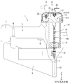
- FIG. 7 shows the driving tool 30 according to the second embodiment.
- the filling valve 32, the relief valve 33, and the opening valve 34 included in the accumulator chamber 31 are different from those in the first embodiment.
- the same symbols are used and the description thereof will be omitted.
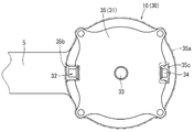
- the filling valve 32, the relief valve 33, and the opening valve 34 are arranged in the upper housing 35 which constitutes the upper part of the tool housing 11. Similar to the first embodiment, the outer surface of the upper housing 35 is also coated with the elastic rubber layer 35a for shock absorption.
- the filling valve 32 has the same configuration as the filling valve 22 according to the first embodiment. However, the orientation of the arrangement is different from that of the first embodiment.
- the filling valve 32 is arranged laterally so that the plunger axis J intersects (orthogonally) the reciprocating direction of the striking piston 13. Therefore, the plunger 32a of the filling valve 32 is displaced in the direction orthogonal to the driving direction.
- the filling valve 32 is arranged in the valve recess 35b provided in the upper housing 35. Therefore, the filling valve 32 is arranged so as not to protrude from the outer shell of the upper housing 35. As a result, as in the first embodiment, interference of other members with the filling valve 32 can be avoided and damage thereof can be prevented.
- An external device 2 can be connected to the filling valve 32 to quickly fill the accumulator chamber 31 with compressed gas.
- the relief valve 33 and the release valve 34 are arranged so as to be separated from each other. This point is different from the first embodiment in which the relief valve 23 and the opening valve 24 are integrated to form a relief / opening combined valve.
- the relief valve 33 is arranged substantially in the center of the upper housing 35.
- the relief valve 33 is arranged in a vertical direction in which the plunger axis J is parallel to the driving direction as in the first embodiment.
- the relief valve 33 has substantially the same configuration as the relief valve 23 according to the first embodiment.
- the relief valve 33 has a valve frame body 23a, a movable member 23b, and a plunger 23e.
- the plunger 23e is urged toward the closed position by a compression spring 23f interposed between the plunger 23e and the movable member 23b.
- the movable member 23b is screw-fitted to the inner peripheral side of the valve frame 23a.
- the set pressure of the accumulator chamber 31 can be adjusted by changing the tightening position of the movable member 23b to change the urging force of the compression spring 23f.
- the plunger 23e is displaced to the opening position side against the compression spring 23f.
- the compressed gas is discharged through the opening holes 23j of the movable member 23b, and the pressure accumulator chamber 31 is held at the set pressure.
- the tool engaging portion 23k of the first embodiment operated when the air is open to the atmosphere is omitted. Therefore, the relief valve 33 of the second embodiment is always covered with the elastic rubber layer 35a without protruding from the outer shell of the upper housing 35.
- the relief valve 33 according to the second embodiment is not operated for opening the accumulator chamber 31 to the atmosphere.
- the movable member 23b is rotated only during maintenance in which the set pressure of the accumulator chamber 31 is changed.
- the opening valve 34 is used to open the accumulator chamber 31 to the atmosphere.
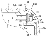
- the release valve 34 is arranged in the second valve recess 35c provided on the side of the upper housing 35.
- the release valve 34 has a head portion 34a having a hexagonal hole 34c and a screw shaft portion 34b.
- a seal member 34d is attached to the lower surface of the head 34a.
- the screw shaft portion 34b of the open valve 34 is screwed into the screw hole 35d provided in the vertical wall portion 35f of the second valve recess 35c.
- a hexagon wrench (not shown) can be engaged with the hexagonal hole 34c of the head 34a to rotate the opening valve 34.
- the tightening position of the screw shaft portion 34b with respect to the screw hole 35d changes by the rotation operation of the release valve 34.
- the release valve 34 is displaced in the axial direction (corresponding to the plunger axis J).
- the screw hole 35d is provided with an open groove 35e along the axial direction thereof.
- the open groove 35e reaches the vertical wall portion 35f from the accumulator chamber 31 side and penetrates the upper housing 35 in the wall thickness direction.
- the release valve 34 When the release valve 34 is rotated to the working position side, the release valve 34 moves to the right side as shown in FIG. 9, and the screw shaft portion 34b is tightened shallowly with respect to the screw hole 35d. As a result, the seal member 34d is separated from the opening groove 35e, and the accumulator chamber 31 is opened to the atmosphere. By opening the accumulator chamber 31 to the atmosphere, the work of removing the nails of the driving nose portion 18 can be performed quickly.
- the driving tool 30 also has a filling valve 32, a relief valve 33, and an opening valve 34 in the accumulator chamber 31.
- An external device 2 can be connected to the filling valve 32 to quickly fill the accumulator chamber 31 with compressed gas.
- the relief valve 33 can hold the accumulator chamber 31 at a set pressure.
- the release valve 34 opens the accumulator chamber 31 to the atmosphere so that the nail removal operation can be performed quickly and easily.
- the filling valve 32, the relief valve 33, and the opening valve 34 are arranged independently of each other. Therefore, good operability of each valve 32, 33, 34 is ensured. In addition, the degree of freedom in arranging the valves 32, 33, and 34 is increased.
- the filling valve 32 and the opening valve 34 are arranged sideways, respectively.
- the plunger axis J of the filling valve 32 and the opening valve 34 intersects in the moving direction of the striking piston 13.
- the degree of freedom in the arrangement direction (direction of the plunger axis J) of the filling valve 32, the relief valve 33, and the opening valve 34 is increased.
- the filling valve 32, the relief valve 33, and the opening valve 34 are all arranged above the cylinder 12. Therefore, the configuration around the cylinder 12 is simplified, and the driving tool 30 can be slimmed down.
- the filling valve 32, the relief valve 33, and the opening valve 34 are arranged so as not to protrude from the outer shell of the upper housing 35. As a result, it is possible to avoid interference of other articles and the like with each valve 32, 33, 34 and prevent damage thereof.
- the pressure in the accumulator chamber 20 rises by moving the striking piston 13 up to the top dead center by the drive mechanism having the electric motor 17. In this way, the pressure required for the striking motion is secured by utilizing the upward motion of the striking piston 13. Therefore, no special means for increasing the pressure in the accumulator chamber 20 is required.
- the upper housings 21 and 35 are formed in a concave shape and used as the valve frame 23a.
- the relief valves 23 and 33 may be assembled by using a dedicated valve frame 22a such as the filling valves 22 and 32.
- a pressing roller type or a hoisting type can be adopted instead of the rack and pinion type.
- the valve structure illustrated can also be applied to the tacker in which the staple is used as the driving tool.
- the third embodiment is shown in FIGS. 11 to 13.
- the driving tool system S in which the driving tool 40 is filled with the compressed gas by using the adapter 50 is exemplified.
- the driving tool system S supplies the driving tool 40 with compressed gas as a power source.
- a gas spring type driving tool for driving the driving tools n one by one as in the first and second embodiments is exemplified.
- the driving tool 40 has a tool main body portion 10, a handle portion 5, a magazine 9, and a driving nose portion 18 in which a striking mechanism and a drive mechanism are incorporated.
- the description of other members and configurations similar to those of the first and second embodiments will be omitted by using the symbols of agreement.
- the upper housing 21 is airtightly connected to the upper part of the tool housing 11.
- the pressure accumulator chamber 41 is located inside the upper housing 21 and above the striking piston 13.
- the accumulator chamber 41 is provided with a filling valve 42 and an opening valve 43.
- the filling valve 42 includes a cylindrical valve frame body 42a and a plunger 42b displaceably supported by the valve frame body 42a as in the first and second embodiments.
- the plunger 42b is urged to the closed side by the compression spring 42c.
- the on-off valve 43 has the same configuration as the on-off valve 34 of the second embodiment.
- the accumulator chamber 41 is filled with the compressed gas by attaching the adapter 50 to the filling valve 42.
- the adapter 50 has a substantially cylindrical shape that is long in the vertical direction and has a ventilation path 50a on the inner peripheral side.
- a first connection port 51 dedicated to the connection form with respect to the filling adapter 42 is provided at the lower part of the adapter 50.
- the upper part of the adapter 50 has a highly versatile second connection port 52 whose connection form is defined by a standard or the like.
- the first connection port 51 is provided with an opening pin 51a.
- An on-off valve 54 is non-removably attached to the second connection port 52.
- the on-off valve 54 includes a cylindrical frame body 54a and one plunger 54b supported by the frame body 54a.
- the plunger 54b is urged to the closed side by the compression spring 54c.
- the nozzle 61 of the external compressed gas supply device 60 is connected to the second connection port 52.
- An opening pin 62 is provided on the inner peripheral side of the nozzle 61.
- the adapter 50 is provided with a relief valve 53.
- the relief valve 53 is provided in the middle of the ventilation path 50a.
- the relief valve 53 has a configuration in which one plunger 53b is supported on the valve frame 53a.
- the plunger 53b is urged to the closed side by a compression spring 53c.
- the relief valve 53 has a configuration similar to that of the relief valve 33 of the second embodiment.
- the adapter 50 is used when the accumulator chamber 41 is filled with the compressed gas.
- the relief valve 53 provided in the adapter 50 avoids the supply of excessive compressed gas, and the gas pressure in the accumulator chamber 41 is maintained at the set pressure.
- the adapter 50 is removed from the filling valve 42 when the accumulator chamber 41 is completely filled with the compressed gas or is not filled. Therefore, the relief valve 53 is also removed together with the adapter 50. Therefore, the relief valve 53 is protected from vibrations and impacts generated by driving the gas driving device (driving tool 40).
- the relief valve 53 is attached to the driving tool 40 only when necessary (when filled with gas), and is removed when the driving tool 40 is driven, so that the relief valve 53 is durable. The sex is enhanced.
- the second connection port 52 of the adapter 50 has a general-purpose connection form defined by a standard or the like, and the first connection port 51 has a connection form dedicated to the driving tool system S. .. Therefore, as the on-off valve 54 of the adapter 50, a valve that is not compatible with the filling valve 42 (for example, the opening size for connection is different) is used. Therefore, the compressed gas supply device 60 cannot be directly connected to the filling valve 42, and the adapter 50 must be used for the work of filling the accumulator chamber 41 with the compressed gas.
- the work of filling the accumulator chamber 41 with the compressed gas can be quickly performed by using the adapter 50 having the relief valve 53. Further, the relief valve 53 keeps the accumulator chamber 41 at a set pressure. The release valve 43 opens the accumulator chamber 41 to the atmosphere so that the work of removing nails can be performed quickly and easily.
- the adapter 50 is removed in a state where the accumulator chamber 41 is not filled with the compressed gas (for example, during the driving operation).
- the relief valve 53 is protected from the impact at the time of driving. Therefore, the durability of the relief valve 53 is enhanced.
- the opening / closing valve 54 of the second connection port 52 is not compatible with the filling valve 42 due to the difference in the connection form such as the opening size. Therefore, the external compressed gas supply device 60 cannot be directly connected to the filling valve 42. As a result, it is necessary to use the adapter 50 having the relief valve 53 in the work of filling the accumulator chamber 41 with the compressed gas. As a result, the filling operation is performed only in a situation where the relief valve 53 avoids the supply of excessive compressed gas. Therefore, excessive supply of compressed gas to the accumulator chamber is avoided.
- the driving tool 1 in the embodiment is an example of the driving tool in one aspect of the present disclosure.
- the striking piston 13 in the embodiment is an example of a striking piston in one aspect of the present disclosure.
- the electric motor 17 in the embodiment is an example of the electric motor in one aspect of the present disclosure.
- the accumulator chamber 20 in the embodiment is an example of the accumulator chamber in one aspect of the present disclosure.
- the filling valves 22 and 32 in the embodiment are examples of filling valves in one aspect of the present disclosure.
- Relief valves 23, 33 in the embodiment are examples of relief valves in one aspect of the present disclosure.
- the release valves 24, 34 in the embodiment are examples of the release valves in one aspect of the present disclosure.
- the external device 2 in the embodiment is an example of the external device in one aspect of the present disclosure.
- the connection port 22f in the embodiment is an example of the connection port in one aspect of the present disclosure.
- the cylinder 12 in the embodiment is an example of a cylinder in one aspect of the present disclosure.
- the tool housing 11 in the embodiment is an example of the tool housing in one aspect of the present disclosure.
- the valve recesses 25 and 35b in the embodiment are examples of the valve recesses in one aspect of the present disclosure.
- the plunger 23e in the embodiment is an example of the plunger in one aspect of the present disclosure.
- the movable member 23b in the embodiment is an example of the movable member in one aspect of the present disclosure.
- the compression spring 23f in the embodiment is an example of an elastic member in one aspect of the present disclosure.
- the tool engaging portion 23k in the embodiment is an example of the tool engaging portion in one aspect of the present disclosure.
- the second valve recess 35c in the embodiment is an example of the second valve recess in one aspect of the present disclosure.
- the plunger 32a in the embodiment is an example of a plunger in one aspect of the present disclosure.
- the driving tool system S in the embodiment is an example of the driving tool system in another aspect of the present disclosure.
- the driving tool 40 in the embodiment is an example of a driving tool in another aspect of the present disclosure.
- the adapter 50 in the embodiment is an example of an adapter in another aspect of the present disclosure.
- the relief valve 53 in the embodiment is an example of a relief valve in another aspect of the present disclosure.
- the first connection port 51 in the embodiment is an example of the first connection port in another aspect of the present disclosure.
- the second connection port 52 in the embodiment is an example of the second connection port in another aspect of the present disclosure.
- the external compressed gas supply device 60 in the embodiment is an example of the compressed gas supply device in another aspect of the present disclosure.
Landscapes
- Engineering & Computer Science (AREA)
- Mechanical Engineering (AREA)
- Physics & Mathematics (AREA)
- Fluid Mechanics (AREA)
- Portable Nailing Machines And Staplers (AREA)
Priority Applications (4)
| Application Number | Priority Date | Filing Date | Title |
|---|---|---|---|
| DE112021000721.1T DE112021000721T5 (de) | 2020-03-24 | 2021-03-02 | Eintreibwerkzeug |
| US17/801,138 US12115634B2 (en) | 2020-03-24 | 2021-03-02 | Driving tool |
| CN202180023403.6A CN115315339B (zh) | 2020-03-24 | 2021-03-02 | 打入工具 |
| JP2022509451A JP7295335B2 (ja) | 2020-03-24 | 2021-03-02 | 打ち込み工具 |
Applications Claiming Priority (2)
| Application Number | Priority Date | Filing Date | Title |
|---|---|---|---|
| JP2020052259 | 2020-03-24 | ||
| JP2020-052259 | 2020-03-24 |
Publications (1)
| Publication Number | Publication Date |
|---|---|
| WO2021192838A1 true WO2021192838A1 (ja) | 2021-09-30 |
Family
ID=77890142
Family Applications (1)
| Application Number | Title | Priority Date | Filing Date |
|---|---|---|---|
| PCT/JP2021/007840 Ceased WO2021192838A1 (ja) | 2020-03-24 | 2021-03-02 | 打ち込み工具 |
Country Status (5)
| Country | Link |
|---|---|
| US (1) | US12115634B2 (https=) |
| JP (1) | JP7295335B2 (https=) |
| CN (1) | CN115315339B (https=) |
| DE (1) | DE112021000721T5 (https=) |
| WO (1) | WO2021192838A1 (https=) |
Cited By (5)
| Publication number | Priority date | Publication date | Assignee | Title |
|---|---|---|---|---|
| US20220395972A1 (en) * | 2021-06-10 | 2022-12-15 | Makita Corporation | Power tool having rotary hammer mechanism |
| WO2023032331A1 (ja) * | 2021-08-31 | 2023-03-09 | 工機ホールディングス株式会社 | 作業機 |
| EP4212285A1 (en) * | 2021-12-28 | 2023-07-19 | Basso Industry Corp. | Electric nail gun |
| US12162125B2 (en) | 2020-10-30 | 2024-12-10 | Milwaukee Electric Tool Corporation | Powered fastener driver |
| US12403575B2 (en) | 2021-07-16 | 2025-09-02 | Milwaukee Electric Tool Corporation | Gas spring-powered fastener driver with pressure mechanism |
Families Citing this family (3)
| Publication number | Priority date | Publication date | Assignee | Title |
|---|---|---|---|---|
| USD1015105S1 (en) * | 2021-12-21 | 2024-02-20 | Zhejiang Prulde Electric Appliance Co., Ltd. | Nail gun |
| WO2025066877A1 (zh) * | 2023-09-27 | 2025-04-03 | 南京泉峰科技有限公司 | 动力工具 |
| CN117506813A (zh) * | 2023-11-15 | 2024-02-06 | 杭州科龙电器工具有限公司 | 一种能适配多工况和方便维护的钉枪及方法 |
Citations (5)
| Publication number | Priority date | Publication date | Assignee | Title |
|---|---|---|---|---|
| JPH07156075A (ja) * | 1993-12-02 | 1995-06-20 | Kanematsu Nnk Corp | 固着具打撃工具 |
| JP2006218587A (ja) * | 2005-02-14 | 2006-08-24 | Hitachi Koki Co Ltd | 釘打機 |
| JP2014233770A (ja) * | 2013-05-31 | 2014-12-15 | 日立工機株式会社 | 打込機 |
| WO2017187892A1 (ja) * | 2016-04-28 | 2017-11-02 | 日立工機株式会社 | 打込機 |
| JP2019209395A (ja) * | 2018-05-31 | 2019-12-12 | 工機ホールディングス株式会社 | 打込機 |
Family Cites Families (5)
| Publication number | Priority date | Publication date | Assignee | Title |
|---|---|---|---|---|
| KR20090119872A (ko) * | 2007-03-08 | 2009-11-20 | 마크스 가부시기가이샤 | 공기압공구 |
| WO2016136632A1 (ja) * | 2015-02-26 | 2016-09-01 | 日立工機株式会社 | 打込機 |
| GB2556457B (en) * | 2015-04-30 | 2021-10-13 | Koki Holdings Co Ltd | Fastener driving machine |
| CN208697341U (zh) * | 2015-05-27 | 2019-04-05 | 工机控股株式会社 | 打桩机 |
| TWI751176B (zh) * | 2016-08-31 | 2022-01-01 | 日商工機控股股份有限公司 | 打釘機、壓力調節器和打釘單元 |
-
2021
- 2021-03-02 DE DE112021000721.1T patent/DE112021000721T5/de active Pending
- 2021-03-02 CN CN202180023403.6A patent/CN115315339B/zh active Active
- 2021-03-02 US US17/801,138 patent/US12115634B2/en active Active
- 2021-03-02 WO PCT/JP2021/007840 patent/WO2021192838A1/ja not_active Ceased
- 2021-03-02 JP JP2022509451A patent/JP7295335B2/ja active Active
Patent Citations (5)
| Publication number | Priority date | Publication date | Assignee | Title |
|---|---|---|---|---|
| JPH07156075A (ja) * | 1993-12-02 | 1995-06-20 | Kanematsu Nnk Corp | 固着具打撃工具 |
| JP2006218587A (ja) * | 2005-02-14 | 2006-08-24 | Hitachi Koki Co Ltd | 釘打機 |
| JP2014233770A (ja) * | 2013-05-31 | 2014-12-15 | 日立工機株式会社 | 打込機 |
| WO2017187892A1 (ja) * | 2016-04-28 | 2017-11-02 | 日立工機株式会社 | 打込機 |
| JP2019209395A (ja) * | 2018-05-31 | 2019-12-12 | 工機ホールディングス株式会社 | 打込機 |
Cited By (8)
| Publication number | Priority date | Publication date | Assignee | Title |
|---|---|---|---|---|
| US12162125B2 (en) | 2020-10-30 | 2024-12-10 | Milwaukee Electric Tool Corporation | Powered fastener driver |
| US20220395972A1 (en) * | 2021-06-10 | 2022-12-15 | Makita Corporation | Power tool having rotary hammer mechanism |
| US12403575B2 (en) | 2021-07-16 | 2025-09-02 | Milwaukee Electric Tool Corporation | Gas spring-powered fastener driver with pressure mechanism |
| US12521854B2 (en) | 2021-07-16 | 2026-01-13 | Milwaukee Electric Tool Corporation | Gas spring-powered fastener driver with pressure mechanism |
| WO2023032331A1 (ja) * | 2021-08-31 | 2023-03-09 | 工機ホールディングス株式会社 | 作業機 |
| JP7655393B2 (ja) | 2021-08-31 | 2025-04-02 | 工機ホールディングス株式会社 | 作業機 |
| EP4212285A1 (en) * | 2021-12-28 | 2023-07-19 | Basso Industry Corp. | Electric nail gun |
| US11986938B2 (en) | 2021-12-28 | 2024-05-21 | Basso Industry Corp. | Electric nail gun |
Also Published As
| Publication number | Publication date |
|---|---|
| US20230071613A1 (en) | 2023-03-09 |
| JPWO2021192838A1 (https=) | 2021-09-30 |
| US12115634B2 (en) | 2024-10-15 |
| DE112021000721T5 (de) | 2023-02-16 |
| CN115315339A (zh) | 2022-11-08 |
| CN115315339B (zh) | 2026-02-17 |
| JP7295335B2 (ja) | 2023-06-20 |
Similar Documents
| Publication | Publication Date | Title |
|---|---|---|
| JP7295335B2 (ja) | 打ち込み工具 | |
| US8016046B2 (en) | Combustion power source with back pressure release for combustion powered fastener-driving tool | |
| CN113084757B (zh) | 打入机 | |
| US12459089B2 (en) | Powered fastener driver | |
| WO2011010512A1 (ja) | 打込み工具 | |
| JP2017131994A (ja) | 打込機 | |
| US20210316433A1 (en) | Driving tool | |
| CN114102521A (zh) | 用于紧固件驱动工具的气弹簧 | |
| WO2018148007A1 (en) | Powered-fastener-driving tool including a driver blade having a varying cross-section | |
| WO2023159833A1 (zh) | 射钉枪用蓄能机构及射钉枪 | |
| CA2576751C (en) | Driver blade with auxiliary combustion chamber for combustion powered fastener-driving tool | |
| JP4687572B2 (ja) | 打込機 | |
| JP2017119330A (ja) | 打込機 | |
| JP5071287B2 (ja) | 空気圧工具 | |
| WO2021241100A1 (ja) | 打込機 | |
| JPH08336766A (ja) | 空気圧式釘打機の減音機構 | |
| JPH0825245A (ja) | エア釘打機のトリガバルブ | |
| JP2018103273A (ja) | 打ち込み工具 | |
| JP7047573B2 (ja) | 打込み工具 | |
| JP2024100032A (ja) | 打ち込み工具 | |
| JP2004058161A (ja) | 圧縮空気駆動釘打機のエネルギー制御機構 | |
| JP6647909B2 (ja) | 打ち込み工具 | |
| JP2025068850A (ja) | 打ち込み工具 | |
| CN116021482A (zh) | 打入工具 |
Legal Events
| Date | Code | Title | Description |
|---|---|---|---|
| 121 | Ep: the epo has been informed by wipo that ep was designated in this application |
Ref document number: 21774831 Country of ref document: EP Kind code of ref document: A1 |
|
| ENP | Entry into the national phase |
Ref document number: 2022509451 Country of ref document: JP Kind code of ref document: A |
|
| 122 | Ep: pct application non-entry in european phase |
Ref document number: 21774831 Country of ref document: EP Kind code of ref document: A1 |