WO2021192838A1 - Knock-in tool - Google Patents
Knock-in tool Download PDFInfo
- Publication number
- WO2021192838A1 WO2021192838A1 PCT/JP2021/007840 JP2021007840W WO2021192838A1 WO 2021192838 A1 WO2021192838 A1 WO 2021192838A1 JP 2021007840 W JP2021007840 W JP 2021007840W WO 2021192838 A1 WO2021192838 A1 WO 2021192838A1
- Authority
- WO
- WIPO (PCT)
- Prior art keywords
- valve
- driving tool
- accumulator chamber
- compressed gas
- plunger
- Prior art date
Links
Images


Classifications
-
- B—PERFORMING OPERATIONS; TRANSPORTING
- B25—HAND TOOLS; PORTABLE POWER-DRIVEN TOOLS; MANIPULATORS
- B25C—HAND-HELD NAILING OR STAPLING TOOLS; MANUALLY OPERATED PORTABLE STAPLING TOOLS
- B25C1/00—Hand-held nailing tools; Nail feeding devices
- B25C1/04—Hand-held nailing tools; Nail feeding devices operated by fluid pressure, e.g. by air pressure
- B25C1/047—Mechanical details
-
- B—PERFORMING OPERATIONS; TRANSPORTING
- B25—HAND TOOLS; PORTABLE POWER-DRIVEN TOOLS; MANIPULATORS
- B25C—HAND-HELD NAILING OR STAPLING TOOLS; MANUALLY OPERATED PORTABLE STAPLING TOOLS
- B25C1/00—Hand-held nailing tools; Nail feeding devices
- B25C1/06—Hand-held nailing tools; Nail feeding devices operated by electric power
-
- B—PERFORMING OPERATIONS; TRANSPORTING
- B25—HAND TOOLS; PORTABLE POWER-DRIVEN TOOLS; MANIPULATORS
- B25C—HAND-HELD NAILING OR STAPLING TOOLS; MANUALLY OPERATED PORTABLE STAPLING TOOLS
- B25C1/00—Hand-held nailing tools; Nail feeding devices
- B25C1/04—Hand-held nailing tools; Nail feeding devices operated by fluid pressure, e.g. by air pressure
- B25C1/041—Hand-held nailing tools; Nail feeding devices operated by fluid pressure, e.g. by air pressure with fixed main cylinder
- B25C1/042—Main valve and main cylinder
Definitions
- This disclosure relates to a driving tool for driving a driving tool such as a nail or a staple into wood or the like.
- Patent Document 1 Patent No. 6519651 discloses that it has a filling valve for filling a pressure accumulator chamber with compressed gas and a relief valve (safety valve) for discharging gas having a constant pressure or higher.
- Patent Document 2 Patent No. 6481751 discloses that it has an outside air intake valve that introduces outside air into the accumulator chamber by the operation inside the tool body.
- Patent Document 2 discloses that, in addition to the outside air intake valve and the relief valve, an open valve that allows an operator to release compressed gas in the accumulator chamber at an arbitrary timing is provided.
- the compression gas in the accumulator chamber can be released with the release valve, so that the nail removal work can be performed easily.
- the accumulator chamber is quickly filled with the compressed gas.
- the driving work can be resumed quickly.
- the conventional outside air intake valve it takes time to fill the gas pressure to a sufficient level because the outside air is taken in by the operation inside the tool body. This point needs to be improved.
- the driving tool has, for example, a striking piston that moves downward in the cylinder to strike the driving tool.
- the striking piston is moved up to top dead center by a drive mechanism using an electric motor as a drive source.
- the thrust of the compressed gas which is the power source for moving the striking piston downward for driving, can be obtained.
- the compressed gas is accumulated in the accumulator chamber.
- the accumulator chamber is filled with compressed gas via a filling valve. Compressed gas is released by the relief valve, and the accumulator chamber is maintained at the set pressure.
- the accumulator chamber is opened to the atmosphere through an open valve.
- the filling valve comprises a connection port that is connected to an external device and allows injection of compressed gas supplied from the external device. Therefore, the gas filling operation of the accumulator chamber can be performed more quickly than in the case of the conventional internal operation of the tool body. As a result, the driving operation can be restarted more quickly.
- the tool has, for example, a cylinder and a tool housing that houses the accumulator chamber.
- the tool housing is formed with a valve recess for preventing the filling valve from protruding from the outer shell of the tool housing. Therefore, it is possible to avoid interference with other members with respect to the filling valve and avoid damage to the filling valve.
- a relief valve also has the function of an open valve. Therefore, the relief valve and the release valve are integrated, the degree of freedom in their arrangement is increased, and the compactness is achieved.
- the relief valve has a plunger that seals the accumulator chamber and a movable member that is displaced by an external operation.
- An elastic member is interposed between the movable member and the plunger. The urging force of the elastic member against the plunger can be adjusted by the displacement of the movable member.
- the urging force of the elastic member is adjusted.
- the gas pressure in the accumulator chamber is adjusted.
- the gas pressure in the accumulator chamber is set high.
- the urging force of the plunger is weakened, the gas pressure in the accumulator chamber is set low. The displacement of the movable member sufficiently weakens the urging force of the elastic member, so that the plunger is fully opened and the accumulator chamber is opened to the atmosphere.
- the movable member is provided with a tool engaging portion into which a tool for moving the movable member is engaged between a normal position and a working position. Therefore, the movable member can be quickly and accurately displaced using a tool.
- the tool has, for example, a cylinder and a tool housing that houses the accumulator chamber.
- the tool housing is formed with a second valve recess for preventing the relief valve and the open valve from protruding from the outer shell of the tool housing. Therefore, the interference of other members with the relief valve and the release valve is avoided, and the damage is avoided in advance.
- a filling valve, a relief valve, and an opening valve are arranged independently of each other. Therefore, the operability of each valve is ensured. In addition, the degree of freedom in arranging each valve is increased.
- At least one valve for example, at least one valve, a filling valve, a relief valve, and an open valve, comprises a plunger that moves along the plunger axis between the closed and open positions.
- the plunger is arranged so that the plunger axis intersects the moving direction of the striking piston. Therefore, the degree of freedom in arranging at least one valve is increased.
- the filling valve, the relief valve and the opening valve are all located above the cylinder. Therefore, the configuration around the cylinder is simplified. As a result, the driving tool can be slimmed down.
- the driving tool system has, for example, a driving tool provided with a pressure accumulator chamber and an adapter used when filling the pressure accumulator chamber of the driving tool with compressed gas.
- the driving tool has a striking piston that moves downward in a cylinder communicating with the accumulator chamber to strike the driving tool.
- the striking piston is moved up to top dead center by a drive mechanism using an electric motor as a drive source.
- the thrust of the compressed gas which is the power source for moving the striking piston downward for driving, is obtained.
- the compressed gas is accumulated in the accumulator chamber.
- a filling valve is provided in the accumulator chamber.
- the accumulator chamber is filled with compressed gas through the filling valve.
- An on-off valve is provided in the accumulator chamber.
- the pressure accumulator chamber is opened to the atmosphere by the on-off valve.
- the adapter has a first connection port that is detachably connected to the filling valve of the driving tool and a second connection port that is detachably connected to an external compressed gas supply device.
- a relief valve is provided on the adapter.
- the accumulator chamber By opening the accumulator chamber to the atmosphere with an open valve, anti-jamming measures can be taken quickly and easily. After the accumulator chamber is opened, the compressed gas is quickly filled into the accumulator chamber from the external compressed gas supply device via the filling valve, instead of the internal operation of the tool body as in the conventional case. As a result, the driving tool can be quickly restarted and the driving work can be continued.
- An external compressed gas supply device is connected to the filling valve via an adapter.
- the excess supply of compressed gas is released into the atmosphere by a relief valve provided in the adapter.
- the accumulator chamber is maintained at the set pressure.
- the adapter is removed from the filling valve when the accumulator chamber is completely filled with compressed gas. Therefore, the driving tool is used with the relief valve removed together with the adapter. As a result, it is possible to protect the relief valve by avoiding an impact at the time of driving.
- the relief valve is installed in the accumulator chamber only when necessary (when filled with compressed gas), and is removed from the accumulator chamber during driving work or the like to enhance the durability of the relief valve.
- a compressor supply nozzle or a gas can be applied to the compressed gas supply device.
- the second connection port has an on-off valve for connecting a compressed gas supply device.
- the connection form of the on-off valve and the filling valve is different from each other. This makes it impossible to connect the compressed gas supply device to the filling valve. Therefore, by using the adapter, it is possible to fill the accumulator chamber with the compressed gas. As a result, the filling operation is performed in a situation where the relief valve ensures that the supply of excess compressed gas is avoided.
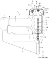
- FIG. 1 shows the driving tool 1 of the first embodiment.
- the driving tool 1 includes a tool main body portion 10, a handle portion 5 gripped by the user, and a magazine 9 capable of loading a large number of driving tools.
- a cylinder 12 is built in the tool housing 11 of the tool body 10.
- the striking piston 13 is installed in the cylinder 12 so as to be able to reciprocate up and down.
- a driver 14 for striking the driving tool n is attached to the center of the lower surface of the striking piston 13.
- a pressure accumulator chamber 20 is provided above the tool body 10.
- the striking piston 13 moves downward due to the pressure (thrust) of the compressed gas as the power source accumulated in the accumulator chamber 20.
- the striking piston 13 moves downward in the cylinder 12, and the striking tool n is striked by the driver 14.
- the striking piston 13 and the driver 14 are returned to the top dead center (driving standby position shown in FIG. 1) by a drive mechanism using the electric motor 17 as a drive source.
- the gas pressure in the accumulator chamber 20 is increased by returning the striking piston 13 to the top dead center by the drive mechanism.
- a rack gear 14a is formed in the driver 14 along the longitudinal direction thereof.
- the pinion gear 16 is meshed with the rack gear 14a.
- the pinion gear 16 is attached to the output shaft of the electric motor 17. After the pinion gear 16 and the rack gear 14a mesh with each other, the driver 14 and the striking piston 13 are moved upward by the rotational output of the electric motor 17.
- the driver 14 and the striking piston 13 are returned to top dead center against the gas pressure in the accumulator chamber 20.
- a compact, high-output brushless motor is used for the electric motor 17.
- the meshing of the electric motor 17, the pinion gear 16, and the rack gear 14a constitutes the drive mechanism.
- a damper 19 is installed on the bottom dead center side of the tool body 10.
- the lower moving end of the striking piston 13 is regulated by the damper 19.
- the driver 14 is inserted on the inner peripheral side of the damper 19.
- the tip portion of the driver 14 has entered the driving passage of the driving nose portion 18 provided in the lower part of the tool main body portion 10.
- the tip of the magazine 9 is connected to the driving nose portion 18.
- the driving tools n are supplied one by one from the magazine 9 into the driving passage.
- the handle portion 5 is provided so as to protrude laterally from the side portion of the tool body portion 10.
- a trigger type switch lever 6 is provided on the lower surface side of the base portion of the handle portion 5. When the user pulls the switch lever 6 with the fingertip of the hand holding the handle portion 5, the electric motor 17 is activated.
- a battery pack 7 as a power source is attached to the tip side of the handle portion 5.
- the battery pack 7 can be used repeatedly by removing it and charging it with a separately prepared charger.
- the electric motor 17 is started by the electric power of the battery pack 7.
- a controller 8 is built in the handle portion 5.
- the controller 8 mainly houses a control board including a control circuit and a power supply circuit for controlling the operation of the electric motor 17.
- the accumulator chamber 20 is partitioned inside the upper housing 21 that constitutes the upper part of the tool housing 11.
- the outer surface of the upper housing 21 is coated with an elastic rubber layer 21a for shock absorption.
- the compressed gas in the accumulator chamber 20 acts on the upper surface of the striking piston 13.
- a filling valve 22, a relief valve 23, and an opening valve 24 are arranged in the accumulator chamber 20.
- An external device 2 for injecting compressed gas is connected to the filling valve 22.
- the compressed gas of the external device 2 connected to the filling valve 22 is filled (replenished) in the accumulator chamber 20 through the connection port 22f of the filling valve 22.
- Excessive compressed gas is automatically released by the relief valve 23, and the gas pressure in the accumulator chamber 20 is maintained at the set pressure.
- the accumulator chamber 20 is forcibly opened to the atmosphere by the operation of the release valve 24 by the user.
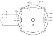
- the upper housing 21 is formed with a valve recess 25 for accommodating the filling valve 22.
- the valve recess 25 has a semi-oval shape when viewed in a plane. By arranging it in the valve recess 25, the filling valve 22 does not protrude from the outer shell of the upper housing 21. As a result, interference of other articles with the filling valve 22 is avoided, and damage or the like thereof is prevented.
- the filling valve 22 has a cylindrical valve frame 22a.
- One plunger 22b is supported on the inner peripheral side of the valve frame 22a so as to be displaceable in the axial direction (plunger axis J).
- a compression spring 22c is interposed between the valve frame 22a and the plunger 22b.
- the tip end side of the plunger 22b is entered into the accumulator chamber 20 from the valve frame body 22a.
- the plunger 22b is urged by a compression spring 22c in a direction in which the tip end side thereof is retracted from the pressure accumulator chamber 20 (upper side in the drawing).
- a flange portion 22d is integrally provided at the tip of the plunger 22b.
- the flange portion 22d prevents the plunger 22b from coming off.
- a seal member 22e is mounted on the upper surface of the flange portion 22d. As shown in FIG. 3, the sealing member 22e is pressed against the connection port 22f provided on the lower surface of the valve frame 22a by the urging force of the compression spring 22c. When the seal member 22e is pressed against the connection port 22f, the connection port 22f is airtightly closed. This corresponds to the closed position of the plunger 22b. At the closed position, leakage of compressed gas in the accumulator chamber 20 is prevented.
- the plunger 22b When the external device 2 is attached to the filling valve 22 as shown in FIG. 4, the plunger 22b is pushed downward against the compression spring 22c by the push shaft portion 2a of the external device 2. As a result, the connection port 22f is opened. This corresponds to the opening position of the plunger 22b. The plunger 22b is opened, and the compressed gas is injected into the accumulator chamber 20 from the external device 2. When the external device 2 is removed, the plunger 22b is returned to the closed position.
- a tire inflator can be used. Instead of this, a gas can filled with a certain amount of compressed gas can be used.
- the function of the release valve 24 is incorporated and integrated into the relief valve 23. Therefore, in the first embodiment, one relief / opening valve is used as the relief valve 23 and the opening valve 24. As shown in FIG. 5, the relief valve 23 is located substantially in the center of the upper housing 21 and above the striking piston 13. As shown in FIG. 1, the relief valve 23 is arranged at a position where its plunger axis J substantially coincides with the driver 14.
- the relief valve 23 has a cylindrical valve frame 23a.
- a part of the upper housing 21 is used as the valve frame body 23a.
- the valve frame 23a is provided so as to protrude into the accumulator chamber 20 and not protrude from the outer shell of the upper housing 21.
- a cylindrical movable member 23b is provided on the inner peripheral side of the valve frame body 23a.
- a male screw portion 23c is formed on the outer peripheral surface of the movable member 23b.
- the male threaded portion 23c is meshed with the female threaded portion 23d formed on the inner peripheral surface of the valve frame body 23a. Therefore, the movable member 23b can be displaced in the axial direction (vertical direction in the drawing) by rotating it around its axis.
- the movable member 23b is movably held in the axial direction with respect to the valve frame 23a by the meshing (holding portion) between the male screw portion 23c and the female screw portion 23d.
- a plunger 23e is held on the inner peripheral side of the movable member 23b so as to be movable in the axial direction.
- the axis of the valve frame 23a, the axis of the movable member 23b, and the axis of the plunger 23e are the same.
- each axis is referred to as a plunger axis J.
- the plunger 23e is movably held along the plunger axis J.
- the plunger 23e is movably held between a closed position for sealing the accumulator chamber 20 and an open position for opening the accumulator chamber 20.
- the movable member 23b described above is movably held between the normal position and the working position along the plunger axis J.
- a compression spring 23f is interposed between the movable member 23b and the plunger 23e.
- the tip of the plunger 23e is inserted into the ventilation hole 23g of the valve frame 23a.
- the plunger 23e is inserted through the ventilation hole 23g and supported so as to be displaceable in the plunger axis J direction.
- the plunger 23e is urged toward the closed position side (downward in the figure) by the compression spring 23f.
- the plunger 23e is held in the lower closed position by the urging force of the compression spring 23f.
- the plunger 23e is displaced to the upper opening position against the urging force of the compression spring 23f.
- a seal ring 23h is interposed between the tip of the plunger 23e and the ventilation hole 23g.
- the airtight hole 23g is airtightly sealed by the seal ring 23h.
- a slit 23i for ventilation is provided at the tip of the plunger 23e.
- the slit 23i extends to a certain range along the plunger axis J.
- the slits 23i are arranged at two opposing positions around the plunger axis J.
- the plunger 23e is displaced in the plunger axis J direction so that the gas pressure in the accumulator chamber 20 and the urging force of the compression spring 23f are in equilibrium.
- the gas pressure of the accumulator chamber 20 applied to the plunger 23e is smaller than the urging force of the compression spring 23f, the plunger 23e is held in the lower closed position.
- the portion of the plunger 23e where the slit 23i does not exist is located on the inner peripheral side of the seal ring 23h.
- the ventilation holes 23 g are hermetically sealed.
- the accumulator chamber 20 is hermetically sealed to the outside, and the accumulator chamber 20 is held at a constant pressure (below a set pressure).
- the plunger 23e When the gas pressure of the accumulator chamber 20 applied to the plunger 23e becomes larger than the urging force of the compression spring 23f, the plunger 23e is displaced to the upper opening position against the urging force of the compression spring 23f. When the plunger 23e is displaced to the upper opening position, the slit 23i is located on the inner peripheral side of the seal ring 23h. In this state, the airtightness of the ventilation holes 23g is released.
- An opening hole 23j that communicates the inner peripheral side and the outer peripheral side is provided in the upper part of the movable member 23b. Therefore, when the plunger 23e is displaced to the upper opening position and the airtightness of the ventilation hole 23g is released, the pressure accumulator chamber 20 has the ventilation hole 23g, the inner peripheral side of the valve frame 23a, and the inner peripheral side of the movable member 23b. It is opened to the outside (atmosphere side) through the opening hole 23j. As a result, the compressed gas in the accumulator chamber 20 is released to the outside. When the gas pressure in the accumulator chamber 20 drops to the set pressure, the plunger 23e is returned to the closed position by the urging force of the compression spring 23f, and the accumulator chamber 20 is hermetically sealed.
- the urging force of the compression spring 23f corresponding to the set pressure of the accumulator chamber 20 changes by moving the movable member 23b.
- the urging force of the compression spring 23f increases.
- the movable member 23b is displaced upward, the urging force of the compression spring 23f becomes smaller. Therefore, when the movable member 23b is displaced downward, the set pressure of the accumulator chamber 20 becomes high. As a result, the gas pressure in the accumulator chamber 20 can be increased.
- the set pressure of the accumulator chamber 20 becomes low. This makes it easier for the plunger 23e to be displaced toward the opening position with a lower gas pressure.
- the compression spring 23f is in a state in which the urging force does not act on the plunger 23e. In this state, the compressed gas in the accumulator chamber 20 is in an open state to the atmosphere where all of the compressed gas is released through the ventilation holes 23g, the inner peripheral side of the valve frame 23a, the inner peripheral side of the movable member 23b, and the opening holes 23j.
- the gas pressure acting on the striking piston 13 can be eliminated.
- the work of removing the nails stuck in the driving nose portion 18 can be performed quickly and easily.
- the position on the upper side of the movable member 23b required to open the accumulator chamber 20 to the atmosphere corresponds to the working position.
- the position on the lower side of the movable member 23b required to set the gas pressure in the accumulator chamber 20 to an appropriate set pressure corresponds to the normal position.
- the relief valve 23 has a function of holding the movable member 23b at the normal position and holding the accumulator chamber 20 at the set pressure.
- the relief valve 23 also has a function as an opening valve 24 that opens the accumulator chamber 20 to the atmosphere by displacing the movable member 23b to the working position.
- a tool engaging portion 23k for engaging the working tool 26 is provided on the upper portion of the movable member 23b.
- a hexagon wrench hexagon bar wrench
- a hexagonal hole is provided as the tool engaging portion 23k.
- the tool engaging portion 23k penetrates from the upper surface of the movable member 23b toward the inner peripheral side. As shown in FIG. 6, the tool 26 is engaged with the tool engaging portion 23k, and the movable member 23b can be rotated to displace it up and down. As a result, the movable member 23b can be quickly and accurately displaced between the normal position and the working position.
- the accumulator chamber 20 includes a filling valve 22, a relief valve 23, and an opening valve 24.
- a filling valve 22 By opening the accumulator chamber 20 to the atmosphere with the release valve 24, anti-jamming measures and the like can be taken quickly and easily.
- the compressed gas is rapidly filled into the accumulator chamber 20 from the external device 2 through the connection port 22f of the filling valve 22.
- the driving tool 1 can be restarted quickly and the driving work can be continued as compared with the conventional configuration in which the tool body is filled by the internal operation.
- the filling valve 22 is arranged in the valve recess 25 provided in the upper housing 21 of the accumulator chamber 20. This prevents the filling valve 22 from protruding from the outer shell of the tool housing 11 or the upper housing 21. Therefore, it is possible to avoid interference with other members with respect to the filling valve 22 and avoid damage thereof.
- the relief valve 23 is integrated with the release valve 24, and a single valve has both functions. As a result, the degree of freedom in arranging the relief valve 23 and the release valve 24 is increased, and the tool body 10 can be made compact.
- the plunger 23e moves to the opening position against the urging force of the compression spring 23f, and the compressed gas in the accumulator chamber 20 is released.
- the pressure accumulator chamber 20 is held at the set pressure.
- the set pressure of the accumulator chamber 20 can be adjusted by changing the urging force of the compression spring 23f.
- the urging force of the compression spring 23f can be changed by displacing the movable member 23b.
- the urging force of the compression spring 23f can be applied to the plunger 23e.
- the range in which the urging force of the compression spring 23f acts on the plunger 23e corresponds to the normal position of the movable member 23b.
- the set pressure of the accumulator chamber 20 can be adjusted by changing the normal position of the movable member 23b.
- the relief valve 23 and the release valve 24 are incorporated in the valve frame 23a provided in the upper housing 21.
- the valve frame 23a is provided so as to project toward the accumulator chamber 20 side.
- the relief valve 23 and the release valve 24 are arranged so as not to protrude from the outer shell of the upper housing 21. Therefore, the valve frame 23a is formed as a recess for the second valve. Therefore, interference of other members with the relief valve 23 and the release valve 24 is avoided, and damage thereof is avoided in advance.
- the filling valve 22, the relief valve 23, and the opening valve 24 are all arranged above the cylinder 12. Therefore, the configuration around the cylinder 12 is simplified. As a result, the driving tool 1 can be slimmed down.
- the pressure in the accumulator chamber 20 rises by moving the striking piston 13 up to the top dead center by the drive mechanism having the electric motor 17. In this way, the pressure required for the striking motion is secured by utilizing the upward motion of the striking piston 13. Therefore, no special means for increasing the pressure in the accumulator chamber 20 is required.
- the movable member 23b may be displaced by using a hand-cranked screwdriver instead of the hexagon wrench as the tool 26.
- a hand-cranked screwdriver instead of the hexagon wrench as the tool 26.
- a minus-shaped or plus-shaped groove portion can be provided instead of the hexagonal hole as the tool engaging portion 23k.
- a knob portion or a lever portion may be provided instead of the tool engaging portion 23k so that the movable member can be moved and operated without using a tool 26 such as a hexagon wrench.
- FIG. 7 shows the driving tool 30 according to the second embodiment.
- the filling valve 32, the relief valve 33, and the opening valve 34 included in the accumulator chamber 31 are different from those in the first embodiment.
- the same symbols are used and the description thereof will be omitted.
- the filling valve 32, the relief valve 33, and the opening valve 34 are arranged in the upper housing 35 which constitutes the upper part of the tool housing 11. Similar to the first embodiment, the outer surface of the upper housing 35 is also coated with the elastic rubber layer 35a for shock absorption.
- the filling valve 32 has the same configuration as the filling valve 22 according to the first embodiment. However, the orientation of the arrangement is different from that of the first embodiment.
- the filling valve 32 is arranged laterally so that the plunger axis J intersects (orthogonally) the reciprocating direction of the striking piston 13. Therefore, the plunger 32a of the filling valve 32 is displaced in the direction orthogonal to the driving direction.
- the filling valve 32 is arranged in the valve recess 35b provided in the upper housing 35. Therefore, the filling valve 32 is arranged so as not to protrude from the outer shell of the upper housing 35. As a result, as in the first embodiment, interference of other members with the filling valve 32 can be avoided and damage thereof can be prevented.
- An external device 2 can be connected to the filling valve 32 to quickly fill the accumulator chamber 31 with compressed gas.
- the relief valve 33 and the release valve 34 are arranged so as to be separated from each other. This point is different from the first embodiment in which the relief valve 23 and the opening valve 24 are integrated to form a relief / opening combined valve.
- the relief valve 33 is arranged substantially in the center of the upper housing 35.
- the relief valve 33 is arranged in a vertical direction in which the plunger axis J is parallel to the driving direction as in the first embodiment.
- the relief valve 33 has substantially the same configuration as the relief valve 23 according to the first embodiment.
- the relief valve 33 has a valve frame body 23a, a movable member 23b, and a plunger 23e.
- the plunger 23e is urged toward the closed position by a compression spring 23f interposed between the plunger 23e and the movable member 23b.
- the movable member 23b is screw-fitted to the inner peripheral side of the valve frame 23a.
- the set pressure of the accumulator chamber 31 can be adjusted by changing the tightening position of the movable member 23b to change the urging force of the compression spring 23f.
- the plunger 23e is displaced to the opening position side against the compression spring 23f.
- the compressed gas is discharged through the opening holes 23j of the movable member 23b, and the pressure accumulator chamber 31 is held at the set pressure.
- the tool engaging portion 23k of the first embodiment operated when the air is open to the atmosphere is omitted. Therefore, the relief valve 33 of the second embodiment is always covered with the elastic rubber layer 35a without protruding from the outer shell of the upper housing 35.
- the relief valve 33 according to the second embodiment is not operated for opening the accumulator chamber 31 to the atmosphere.
- the movable member 23b is rotated only during maintenance in which the set pressure of the accumulator chamber 31 is changed.
- the opening valve 34 is used to open the accumulator chamber 31 to the atmosphere.
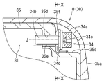
- the release valve 34 is arranged in the second valve recess 35c provided on the side of the upper housing 35.
- the release valve 34 has a head portion 34a having a hexagonal hole 34c and a screw shaft portion 34b.
- a seal member 34d is attached to the lower surface of the head 34a.
- the screw shaft portion 34b of the open valve 34 is screwed into the screw hole 35d provided in the vertical wall portion 35f of the second valve recess 35c.
- a hexagon wrench (not shown) can be engaged with the hexagonal hole 34c of the head 34a to rotate the opening valve 34.
- the tightening position of the screw shaft portion 34b with respect to the screw hole 35d changes by the rotation operation of the release valve 34.
- the release valve 34 is displaced in the axial direction (corresponding to the plunger axis J).
- the screw hole 35d is provided with an open groove 35e along the axial direction thereof.
- the open groove 35e reaches the vertical wall portion 35f from the accumulator chamber 31 side and penetrates the upper housing 35 in the wall thickness direction.
- the release valve 34 When the release valve 34 is rotated to the working position side, the release valve 34 moves to the right side as shown in FIG. 9, and the screw shaft portion 34b is tightened shallowly with respect to the screw hole 35d. As a result, the seal member 34d is separated from the opening groove 35e, and the accumulator chamber 31 is opened to the atmosphere. By opening the accumulator chamber 31 to the atmosphere, the work of removing the nails of the driving nose portion 18 can be performed quickly.
- the driving tool 30 also has a filling valve 32, a relief valve 33, and an opening valve 34 in the accumulator chamber 31.
- An external device 2 can be connected to the filling valve 32 to quickly fill the accumulator chamber 31 with compressed gas.
- the relief valve 33 can hold the accumulator chamber 31 at a set pressure.
- the release valve 34 opens the accumulator chamber 31 to the atmosphere so that the nail removal operation can be performed quickly and easily.
- the filling valve 32, the relief valve 33, and the opening valve 34 are arranged independently of each other. Therefore, good operability of each valve 32, 33, 34 is ensured. In addition, the degree of freedom in arranging the valves 32, 33, and 34 is increased.
- the filling valve 32 and the opening valve 34 are arranged sideways, respectively.
- the plunger axis J of the filling valve 32 and the opening valve 34 intersects in the moving direction of the striking piston 13.
- the degree of freedom in the arrangement direction (direction of the plunger axis J) of the filling valve 32, the relief valve 33, and the opening valve 34 is increased.
- the filling valve 32, the relief valve 33, and the opening valve 34 are all arranged above the cylinder 12. Therefore, the configuration around the cylinder 12 is simplified, and the driving tool 30 can be slimmed down.
- the filling valve 32, the relief valve 33, and the opening valve 34 are arranged so as not to protrude from the outer shell of the upper housing 35. As a result, it is possible to avoid interference of other articles and the like with each valve 32, 33, 34 and prevent damage thereof.
- the pressure in the accumulator chamber 20 rises by moving the striking piston 13 up to the top dead center by the drive mechanism having the electric motor 17. In this way, the pressure required for the striking motion is secured by utilizing the upward motion of the striking piston 13. Therefore, no special means for increasing the pressure in the accumulator chamber 20 is required.
- the upper housings 21 and 35 are formed in a concave shape and used as the valve frame 23a.
- the relief valves 23 and 33 may be assembled by using a dedicated valve frame 22a such as the filling valves 22 and 32.
- a pressing roller type or a hoisting type can be adopted instead of the rack and pinion type.
- the valve structure illustrated can also be applied to the tacker in which the staple is used as the driving tool.
- the third embodiment is shown in FIGS. 11 to 13.
- the driving tool system S in which the driving tool 40 is filled with the compressed gas by using the adapter 50 is exemplified.
- the driving tool system S supplies the driving tool 40 with compressed gas as a power source.
- a gas spring type driving tool for driving the driving tools n one by one as in the first and second embodiments is exemplified.
- the driving tool 40 has a tool main body portion 10, a handle portion 5, a magazine 9, and a driving nose portion 18 in which a striking mechanism and a drive mechanism are incorporated.
- the description of other members and configurations similar to those of the first and second embodiments will be omitted by using the symbols of agreement.
- the upper housing 21 is airtightly connected to the upper part of the tool housing 11.
- the pressure accumulator chamber 41 is located inside the upper housing 21 and above the striking piston 13.
- the accumulator chamber 41 is provided with a filling valve 42 and an opening valve 43.
- the filling valve 42 includes a cylindrical valve frame body 42a and a plunger 42b displaceably supported by the valve frame body 42a as in the first and second embodiments.
- the plunger 42b is urged to the closed side by the compression spring 42c.
- the on-off valve 43 has the same configuration as the on-off valve 34 of the second embodiment.
- the accumulator chamber 41 is filled with the compressed gas by attaching the adapter 50 to the filling valve 42.
- the adapter 50 has a substantially cylindrical shape that is long in the vertical direction and has a ventilation path 50a on the inner peripheral side.
- a first connection port 51 dedicated to the connection form with respect to the filling adapter 42 is provided at the lower part of the adapter 50.
- the upper part of the adapter 50 has a highly versatile second connection port 52 whose connection form is defined by a standard or the like.
- the first connection port 51 is provided with an opening pin 51a.
- An on-off valve 54 is non-removably attached to the second connection port 52.
- the on-off valve 54 includes a cylindrical frame body 54a and one plunger 54b supported by the frame body 54a.
- the plunger 54b is urged to the closed side by the compression spring 54c.
- the nozzle 61 of the external compressed gas supply device 60 is connected to the second connection port 52.
- An opening pin 62 is provided on the inner peripheral side of the nozzle 61.
- the adapter 50 is provided with a relief valve 53.
- the relief valve 53 is provided in the middle of the ventilation path 50a.
- the relief valve 53 has a configuration in which one plunger 53b is supported on the valve frame 53a.
- the plunger 53b is urged to the closed side by a compression spring 53c.
- the relief valve 53 has a configuration similar to that of the relief valve 33 of the second embodiment.
- the adapter 50 is used when the accumulator chamber 41 is filled with the compressed gas.
- the relief valve 53 provided in the adapter 50 avoids the supply of excessive compressed gas, and the gas pressure in the accumulator chamber 41 is maintained at the set pressure.
- the adapter 50 is removed from the filling valve 42 when the accumulator chamber 41 is completely filled with the compressed gas or is not filled. Therefore, the relief valve 53 is also removed together with the adapter 50. Therefore, the relief valve 53 is protected from vibrations and impacts generated by driving the gas driving device (driving tool 40).
- the relief valve 53 is attached to the driving tool 40 only when necessary (when filled with gas), and is removed when the driving tool 40 is driven, so that the relief valve 53 is durable. The sex is enhanced.
- the second connection port 52 of the adapter 50 has a general-purpose connection form defined by a standard or the like, and the first connection port 51 has a connection form dedicated to the driving tool system S. .. Therefore, as the on-off valve 54 of the adapter 50, a valve that is not compatible with the filling valve 42 (for example, the opening size for connection is different) is used. Therefore, the compressed gas supply device 60 cannot be directly connected to the filling valve 42, and the adapter 50 must be used for the work of filling the accumulator chamber 41 with the compressed gas.
- the work of filling the accumulator chamber 41 with the compressed gas can be quickly performed by using the adapter 50 having the relief valve 53. Further, the relief valve 53 keeps the accumulator chamber 41 at a set pressure. The release valve 43 opens the accumulator chamber 41 to the atmosphere so that the work of removing nails can be performed quickly and easily.
- the adapter 50 is removed in a state where the accumulator chamber 41 is not filled with the compressed gas (for example, during the driving operation).
- the relief valve 53 is protected from the impact at the time of driving. Therefore, the durability of the relief valve 53 is enhanced.
- the opening / closing valve 54 of the second connection port 52 is not compatible with the filling valve 42 due to the difference in the connection form such as the opening size. Therefore, the external compressed gas supply device 60 cannot be directly connected to the filling valve 42. As a result, it is necessary to use the adapter 50 having the relief valve 53 in the work of filling the accumulator chamber 41 with the compressed gas. As a result, the filling operation is performed only in a situation where the relief valve 53 avoids the supply of excessive compressed gas. Therefore, excessive supply of compressed gas to the accumulator chamber is avoided.
- the driving tool 1 in the embodiment is an example of the driving tool in one aspect of the present disclosure.
- the striking piston 13 in the embodiment is an example of a striking piston in one aspect of the present disclosure.
- the electric motor 17 in the embodiment is an example of the electric motor in one aspect of the present disclosure.
- the accumulator chamber 20 in the embodiment is an example of the accumulator chamber in one aspect of the present disclosure.
- the filling valves 22 and 32 in the embodiment are examples of filling valves in one aspect of the present disclosure.
- Relief valves 23, 33 in the embodiment are examples of relief valves in one aspect of the present disclosure.
- the release valves 24, 34 in the embodiment are examples of the release valves in one aspect of the present disclosure.
- the external device 2 in the embodiment is an example of the external device in one aspect of the present disclosure.
- the connection port 22f in the embodiment is an example of the connection port in one aspect of the present disclosure.
- the cylinder 12 in the embodiment is an example of a cylinder in one aspect of the present disclosure.
- the tool housing 11 in the embodiment is an example of the tool housing in one aspect of the present disclosure.
- the valve recesses 25 and 35b in the embodiment are examples of the valve recesses in one aspect of the present disclosure.
- the plunger 23e in the embodiment is an example of the plunger in one aspect of the present disclosure.
- the movable member 23b in the embodiment is an example of the movable member in one aspect of the present disclosure.
- the compression spring 23f in the embodiment is an example of an elastic member in one aspect of the present disclosure.
- the tool engaging portion 23k in the embodiment is an example of the tool engaging portion in one aspect of the present disclosure.
- the second valve recess 35c in the embodiment is an example of the second valve recess in one aspect of the present disclosure.
- the plunger 32a in the embodiment is an example of a plunger in one aspect of the present disclosure.
- the driving tool system S in the embodiment is an example of the driving tool system in another aspect of the present disclosure.
- the driving tool 40 in the embodiment is an example of a driving tool in another aspect of the present disclosure.
- the adapter 50 in the embodiment is an example of an adapter in another aspect of the present disclosure.
- the relief valve 53 in the embodiment is an example of a relief valve in another aspect of the present disclosure.
- the first connection port 51 in the embodiment is an example of the first connection port in another aspect of the present disclosure.
- the second connection port 52 in the embodiment is an example of the second connection port in another aspect of the present disclosure.
- the external compressed gas supply device 60 in the embodiment is an example of the compressed gas supply device in another aspect of the present disclosure.
Abstract
In gas-spring-type knock-in tools in which an impact piston is returned to top dead center by using an electric motor as a drive source, thereby raising the gas pressure in a pressure accumulation chamber, causing the impact piston to move downward, and knocking in a knock-in implement, filling the prior-art pressure accumulation chamber with compressed gas and opening said chamber to the atmosphere takes time, and operations for resolving nail jamming have been troublesome. It is necessary to implement a more operable measure against jamming. A pressure accumulation chamber (20) is provided with a filling valve (22), a relief valve (23), and an opening valve (24). Connecting an external device (2) to the filing valve (22) makes it possible to quickly fill the pressure accumulation chamber (20) with compressed gas. The pressure accumulation chamber (20) is held at a set pressure by the relief valve (23). The pressure accumulation chamber (20) can be quickly opened to the atmosphere using the opening valve (24). This makes it possible to quickly perform an operation for resolving nail jamming in a knock-in nose part (18).
Description
本開示は、釘やステープル等の打ち込み具を木材等に打ち込むための打ち込み工具に関する。
This disclosure relates to a driving tool for driving a driving tool such as a nail or a staple into wood or the like.
この種の打ち込み工具には、いわゆるガスバネ式と称される打ち込み工具が提供されている。ガスバネ式の打ち込み工具では、蓄圧室に充填した圧縮ガスの膨張力で打撃ピストンが下動して打ち込み具が打撃される。特許文献1(特許第6519651号公報)には、蓄圧室に圧縮ガスを充填するための充填バルブと、一定圧以上のガスを放出するリリーフバルブ(安全バルブ)を有することが開示されている。特許文献2(特許第6481751号公報)には、工具本体内部の動作により蓄圧室に外気を導入する外気取り込み弁を有することが開示されている。特許文献2には、外気取り込み弁、リリーフバルブの他に、作業者が任意にタイミングで蓄圧室の圧縮ガスを放出できる開放バルブを有することが開示されている。
For this type of driving tool, a so-called gas spring type driving tool is provided. In the gas spring type driving tool, the striking piston moves downward due to the expansion force of the compressed gas filled in the accumulator chamber, and the striking tool is striked. Patent Document 1 (Patent No. 6519651) discloses that it has a filling valve for filling a pressure accumulator chamber with compressed gas and a relief valve (safety valve) for discharging gas having a constant pressure or higher. Patent Document 2 (Patent No. 6481751) discloses that it has an outside air intake valve that introduces outside air into the accumulator chamber by the operation inside the tool body. Patent Document 2 discloses that, in addition to the outside air intake valve and the relief valve, an open valve that allows an operator to release compressed gas in the accumulator chamber at an arbitrary timing is provided.
例えば釘詰まり(ジャミング)発生時に、開放バルブで蓄圧室の圧縮ガスを開放することで、釘取り除き作業を楽に行うことができる。蓄圧室の圧縮ガスを開放してジャミング対策を施した後では、蓄圧室に圧縮ガスの充填が迅速になされることが望ましい。これにより打ち込み作業を迅速に再開できる。しかしながら、従来の外気取り込み弁では、工具本体内部の動作で外気を取り込むことから十分なガス圧まで充填するには時間が掛かる。この点を改善する必要がある。
For example, when nail clogging (jamming) occurs, the compression gas in the accumulator chamber can be released with the release valve, so that the nail removal work can be performed easily. After the compressed gas in the accumulator chamber is released and anti-jamming measures are taken, it is desirable that the accumulator chamber is quickly filled with the compressed gas. As a result, the driving work can be resumed quickly. However, with the conventional outside air intake valve, it takes time to fill the gas pressure to a sufficient level because the outside air is taken in by the operation inside the tool body. This point needs to be improved.
本開示の1つの局面によると、打ち込み工具は、例えばシリンダ内を下動して打ち込み具を打撃する打撃ピストンを有する。打撃ピストンは、電動モータを駆動源とする駆動機構により上死点に上動される。駆動機構により打撃ピストンが上動されることで、打撃ピストンを打ち込みのために下動させる動力源となる圧縮ガスの推力が得られる。圧縮ガスは蓄圧室に蓄圧される。蓄圧室には、充填バルブを経て圧縮ガスが充填される。リリーフバルブで圧縮ガスが放出されて、蓄圧室が設定圧に維持される。蓄圧室は開放バルブを経て大気開放される。
According to one aspect of the present disclosure, the driving tool has, for example, a striking piston that moves downward in the cylinder to strike the driving tool. The striking piston is moved up to top dead center by a drive mechanism using an electric motor as a drive source. By moving the striking piston upward by the drive mechanism, the thrust of the compressed gas, which is the power source for moving the striking piston downward for driving, can be obtained. The compressed gas is accumulated in the accumulator chamber. The accumulator chamber is filled with compressed gas via a filling valve. Compressed gas is released by the relief valve, and the accumulator chamber is maintained at the set pressure. The accumulator chamber is opened to the atmosphere through an open valve.
従って、開放バルブで蓄圧室を大気開放することでジャミング対策等を迅速かつ楽に行うことができる。蓄圧室の開放後では、従来のように工具本体の内部動作によるのではなく、充填バルブを経て外部から蓄圧室に圧縮ガスが迅速に充填される。これにより、打ち込み工具を迅速に再起動させて打ち込み作業を続行することができる。
Therefore, by opening the accumulator chamber to the atmosphere with an open valve, anti-jamming measures can be taken quickly and easily. After the accumulator chamber is opened, the compressed gas is quickly filled into the accumulator chamber from the outside through the filling valve, instead of the internal operation of the tool body as in the conventional case. As a result, the driving tool can be quickly restarted and the driving work can be continued.
1つ又はそれ以上の実施態様によると、例えば充填バルブは、外部機器に接続されて外部機器から供給される圧縮ガスの注入を許容する接続口を備える。従って、蓄圧室のガス充填作業を、従来の工具本体の内部動作による場合に比して迅速に行うことができる。これにより打ち込み動作をより迅速に再開できる。
According to one or more embodiments, for example, the filling valve comprises a connection port that is connected to an external device and allows injection of compressed gas supplied from the external device. Therefore, the gas filling operation of the accumulator chamber can be performed more quickly than in the case of the conventional internal operation of the tool body. As a result, the driving operation can be restarted more quickly.
1つ又はそれ以上の実施態様によると、例えばシリンダと蓄圧室を収容する工具ハウジングを有する。工具ハウジングには、充填バルブが工具ハウジングの外郭から突出することを避けるためのバルブ用凹部が形成されている。従って、充填バルブに対する他部材との干渉を避けてその損傷を未然に回避できる。
According to one or more embodiments, it has, for example, a cylinder and a tool housing that houses the accumulator chamber. The tool housing is formed with a valve recess for preventing the filling valve from protruding from the outer shell of the tool housing. Therefore, it is possible to avoid interference with other members with respect to the filling valve and avoid damage to the filling valve.
1つ又はそれ以上の実施態様によると、例えばリリーフバルブが開放バルブの機能を併せ持つ。従って、リリーフバルブと開放バルブが一体化されて、その配置の自由度が高まり、コンパクト化が図られる。
According to one or more embodiments, for example, a relief valve also has the function of an open valve. Therefore, the relief valve and the release valve are integrated, the degree of freedom in their arrangement is increased, and the compactness is achieved.
1つ又はそれ以上の実施態様によると、例えばリリーフバルブは、蓄圧室を密閉するプランジャと、外部操作により変位される可動部材とを有する。可動部材とプランジャとの間に弾性部材が介装される。可動部材の変位によりプランジャに対する弾性部材の付勢力を調整可能である。
According to one or more embodiments, for example, the relief valve has a plunger that seals the accumulator chamber and a movable member that is displaced by an external operation. An elastic member is interposed between the movable member and the plunger. The urging force of the elastic member against the plunger can be adjusted by the displacement of the movable member.
従って、可動部材を外部操作により変位させると弾性部材の付勢力が調整される。付勢力が調整されることで蓄圧室のガス圧が調整される。プランジャの付勢力が強められると蓄圧室のガス圧が高く設定される。プランジャの付勢力が弱められると蓄圧室のガス圧が低く設定される。可動部材の変位により弾性部材の付勢力が十分に弱められることで、プランジャが全開されて蓄圧室が大気開放される。
Therefore, when the movable member is displaced by an external operation, the urging force of the elastic member is adjusted. By adjusting the urging force, the gas pressure in the accumulator chamber is adjusted. When the urging force of the plunger is strengthened, the gas pressure in the accumulator chamber is set high. When the urging force of the plunger is weakened, the gas pressure in the accumulator chamber is set low. The displacement of the movable member sufficiently weakens the urging force of the elastic member, so that the plunger is fully opened and the accumulator chamber is opened to the atmosphere.
1つ又はそれ以上の実施態様によると、例えば可動部材には、可動部材を通常位置と作業位置の間で移動させるための工具が係合される工具係合部が設けられる。従って、工具を用いて可動部材を迅速かつ精確に変位させることができる。
According to one or more embodiments, for example, the movable member is provided with a tool engaging portion into which a tool for moving the movable member is engaged between a normal position and a working position. Therefore, the movable member can be quickly and accurately displaced using a tool.
1つ又はそれ以上の実施態様によると、例えばシリンダと蓄圧室を収容する工具ハウジングを有する。工具ハウジングには、リリーフバルブと開放バルブが工具ハウジングの外郭から突出することを避けるための第2バルブ用凹部が形成されている。従って、リリーフバルブと開放バルブに対する他部材の干渉が回避されて、その損傷が未然に回避される。
According to one or more embodiments, it has, for example, a cylinder and a tool housing that houses the accumulator chamber. The tool housing is formed with a second valve recess for preventing the relief valve and the open valve from protruding from the outer shell of the tool housing. Therefore, the interference of other members with the relief valve and the release valve is avoided, and the damage is avoided in advance.
1つ又はそれ以上の実施態様によると、例えば充填バルブと、リリーフバルブと、開放バルブが相互に独立して配置されている。従って、各バルブの操作性が確保される。また、各バルブの配置の自由度が高まる。
According to one or more embodiments, for example, a filling valve, a relief valve, and an opening valve are arranged independently of each other. Therefore, the operability of each valve is ensured. In addition, the degree of freedom in arranging each valve is increased.
1つ又はそれ以上の実施態様によると、例えば充填バルブと、リリーフバルブと、開放バルブの少なくとも1つのバルブは、閉じ位置と開き位置との間をプランジャ軸線上に沿って移動するプランジャを備える。プランジャ軸線が打撃ピストンの移動方向に交差するようにプランジャが配置されている。従って、少なくとも1つのバルブの配置の自由度が高まる。
According to one or more embodiments, for example, at least one valve, a filling valve, a relief valve, and an open valve, comprises a plunger that moves along the plunger axis between the closed and open positions. The plunger is arranged so that the plunger axis intersects the moving direction of the striking piston. Therefore, the degree of freedom in arranging at least one valve is increased.
1つ又はそれ以上の実施態様によると、例えば充填バルブとリリーフバルブと開放バルブは、何れもシリンダよりも上方に配置されている。従って、シリンダの周囲の構成が簡略化される。これにより当該打ち込み工具のスリム化が図られる。
According to one or more embodiments, for example, the filling valve, the relief valve and the opening valve are all located above the cylinder. Therefore, the configuration around the cylinder is simplified. As a result, the driving tool can be slimmed down.
本開示の他の局面によると、打ち込み工具システムは、例えば蓄圧室を具備する打ち込み工具と、打ち込み工具の蓄圧室に圧縮ガスを充填する際に利用されるアダプタを有する。打ち込み工具は、蓄圧室と連通するシリンダ内を下動して打ち込み具を打撃する打撃ピストンを有する。打撃ピストンは、電動モータを駆動源とする駆動機構により上死点に上動される。駆動機構により打撃ピストンが上動されることで、打ち込みのために打撃ピストンを下動させる動力源となる圧縮ガスの推力が得られる。圧縮ガスは蓄圧室に蓄圧される。蓄圧室に充填バルブが設けられる。充填バルブを経て蓄圧室に圧縮ガスが充填される。蓄圧室に開閉バルブが設けられる。開閉バルブにより蓄圧室が大気開放される。アダプタは、打ち込み工具の充填バルブに着脱可能に接続される第1接続口と、外部の圧縮ガス供給器具と着脱可能に接続される第2接続口を有する。アダプタにリリーフバルブが設けられる。
According to another aspect of the present disclosure, the driving tool system has, for example, a driving tool provided with a pressure accumulator chamber and an adapter used when filling the pressure accumulator chamber of the driving tool with compressed gas. The driving tool has a striking piston that moves downward in a cylinder communicating with the accumulator chamber to strike the driving tool. The striking piston is moved up to top dead center by a drive mechanism using an electric motor as a drive source. By moving the striking piston upward by the drive mechanism, the thrust of the compressed gas, which is the power source for moving the striking piston downward for driving, is obtained. The compressed gas is accumulated in the accumulator chamber. A filling valve is provided in the accumulator chamber. The accumulator chamber is filled with compressed gas through the filling valve. An on-off valve is provided in the accumulator chamber. The pressure accumulator chamber is opened to the atmosphere by the on-off valve. The adapter has a first connection port that is detachably connected to the filling valve of the driving tool and a second connection port that is detachably connected to an external compressed gas supply device. A relief valve is provided on the adapter.
従って、開放バルブで蓄圧室を大気開放することでジャミング対策等を迅速かつ楽に行うことができる。蓄圧室の開放後では、従来のように工具本体の内部動作によるのではなく、充填バルブを経て外部の圧縮ガス供給器具から蓄圧室に圧縮ガスが迅速に充填される。これにより、打ち込み工具を迅速に再起動させて打ち込み作業を続行することができる。
Therefore, by opening the accumulator chamber to the atmosphere with an open valve, anti-jamming measures can be taken quickly and easily. After the accumulator chamber is opened, the compressed gas is quickly filled into the accumulator chamber from the external compressed gas supply device via the filling valve, instead of the internal operation of the tool body as in the conventional case. As a result, the driving tool can be quickly restarted and the driving work can be continued.
充填バルブにはアダプタを介して外部の圧縮ガス供給器具が接続される。圧縮ガスの過剰な供給はアダプタに設けたリリーフバルブにより大気に放出される。これにより蓄圧室が設定圧に維持される。蓄圧室への圧縮ガスの充填が完了した段階でアダプタが充填バルブから取り外される。このため、アダプタとともにリリーフバルブが取り外された状態で打ち込み工具が用いられる。これにより、打ち込み時の衝撃等を回避してリリーフバルブの保護を図ることができる。このようにリリーフバルブは必要時(圧縮ガス充填時)のみ蓄圧室に装備され、打ち込み作業時等には蓄圧室から取り外されることでリリーフバルブの耐久性が高められる。圧縮ガス供給器具には、コンプレッサの供給ノズルやガス缶を適用できる。
An external compressed gas supply device is connected to the filling valve via an adapter. The excess supply of compressed gas is released into the atmosphere by a relief valve provided in the adapter. As a result, the accumulator chamber is maintained at the set pressure. The adapter is removed from the filling valve when the accumulator chamber is completely filled with compressed gas. Therefore, the driving tool is used with the relief valve removed together with the adapter. As a result, it is possible to protect the relief valve by avoiding an impact at the time of driving. In this way, the relief valve is installed in the accumulator chamber only when necessary (when filled with compressed gas), and is removed from the accumulator chamber during driving work or the like to enhance the durability of the relief valve. A compressor supply nozzle or a gas can can be applied to the compressed gas supply device.
1つ又はそれ以上の実施態様によると、例えば第2接続口に、圧縮ガス供給器具を接続するための開閉バルブを有する。開閉バルブと充填バルブの接続形態は相互に異なる。これにより、充填バルブに圧縮ガス供給器具を接続不能である。従って、アダプタを用いることによって蓄圧室への圧縮ガスの充填作業が可能となる。これにより、リリーフバルブにより過剰な圧縮ガスの供給が確実に回避される状況で充填作業がなされる。
According to one or more embodiments, for example, the second connection port has an on-off valve for connecting a compressed gas supply device. The connection form of the on-off valve and the filling valve is different from each other. This makes it impossible to connect the compressed gas supply device to the filling valve. Therefore, by using the adapter, it is possible to fill the accumulator chamber with the compressed gas. As a result, the filling operation is performed in a situation where the relief valve ensures that the supply of excess compressed gas is avoided.
次に、本開示の実施形態を図1~図13に基づいて説明する。図1は、第1実施形態の打ち込み工具1を示している。打ち込み工具1は、工具本体部10と、使用者が把持するハンドル部5と、多数の打ち込み具を装填可能なマガジン9を備えている。
Next, the embodiments of the present disclosure will be described with reference to FIGS. 1 to 13. FIG. 1 shows the driving tool 1 of the first embodiment. The driving tool 1 includes a tool main body portion 10, a handle portion 5 gripped by the user, and a magazine 9 capable of loading a large number of driving tools.
工具本体部10の工具ハウジング11にシリンダ12が内装されている。シリンダ12に打撃ピストン13が上下に往復動可能に内装されている。打撃ピストン13の下面中心には打ち込み具nを打撃するためのドライバ14が取り付けられている。
A cylinder 12 is built in the tool housing 11 of the tool body 10. The striking piston 13 is installed in the cylinder 12 so as to be able to reciprocate up and down. A driver 14 for striking the driving tool n is attached to the center of the lower surface of the striking piston 13.
工具本体部10の上部に蓄圧室20が設けられている。蓄圧室20に蓄圧された動力源としての圧縮ガスの圧力(推力)で打撃ピストン13が下動する。打撃ピストン13がシリンダ12内を下動して、打ち込み具nがドライバ14で打撃される。
A pressure accumulator chamber 20 is provided above the tool body 10. The striking piston 13 moves downward due to the pressure (thrust) of the compressed gas as the power source accumulated in the accumulator chamber 20. The striking piston 13 moves downward in the cylinder 12, and the striking tool n is striked by the driver 14.
打撃ピストン13及びドライバ14は、電動モータ17を駆動源とする駆動機構により上死点(図1に示す打ち込み待機位置)に戻される。打撃ピストン13が駆動機構により上死点に戻されることで、蓄圧室20のガス圧が高められる。これにより、打撃ピストン13を打ち込みのために下動させる推力が得られる。ドライバ14にはその長手方向に沿ってラックギヤ14aが形成されている。ラックギヤ14aにピニオンギヤ16が噛み合わされている。ピニオンギヤ16は、電動モータ17の出力軸に取り付けられている。ピニオンギヤ16とラックギヤ14aの噛み合いを経て、電動モータ17の回転出力によりドライバ14及び打撃ピストン13が上動される。ドライバ14及び打撃ピストン13は、蓄圧室20のガス圧に抗して上死点に戻される。電動モータ17には、コンパクトかつ高出力のブラシレスモータが用いられている。電動モータ17及びピニオンギヤ16とラックギヤ14aの噛み合いが駆動機構を構成している。
The striking piston 13 and the driver 14 are returned to the top dead center (driving standby position shown in FIG. 1) by a drive mechanism using the electric motor 17 as a drive source. The gas pressure in the accumulator chamber 20 is increased by returning the striking piston 13 to the top dead center by the drive mechanism. As a result, a thrust that lowers the striking piston 13 for driving is obtained. A rack gear 14a is formed in the driver 14 along the longitudinal direction thereof. The pinion gear 16 is meshed with the rack gear 14a. The pinion gear 16 is attached to the output shaft of the electric motor 17. After the pinion gear 16 and the rack gear 14a mesh with each other, the driver 14 and the striking piston 13 are moved upward by the rotational output of the electric motor 17. The driver 14 and the striking piston 13 are returned to top dead center against the gas pressure in the accumulator chamber 20. A compact, high-output brushless motor is used for the electric motor 17. The meshing of the electric motor 17, the pinion gear 16, and the rack gear 14a constitutes the drive mechanism.
工具本体部10の下死点側にはダンパ19が内装されている。ダンパ19で打撃ピストン13の下動端が規制される。ダンパ19の内周側にドライバ14が挿通されている。ドライバ14の先端部は、工具本体部10の下部に設けた打ち込みノーズ部18の打ち込み通路内に進入している。打ち込みノーズ部18には、マガジン9の先端部が結合されている。打ち込み動作に連動してマガジン9から打ち込み具nが1本ずつ打ち込み通路内に供給される。
A damper 19 is installed on the bottom dead center side of the tool body 10. The lower moving end of the striking piston 13 is regulated by the damper 19. The driver 14 is inserted on the inner peripheral side of the damper 19. The tip portion of the driver 14 has entered the driving passage of the driving nose portion 18 provided in the lower part of the tool main body portion 10. The tip of the magazine 9 is connected to the driving nose portion 18. In conjunction with the driving operation, the driving tools n are supplied one by one from the magazine 9 into the driving passage.
ハンドル部5は、工具本体部10の側部から側方へ突き出す状態に設けられている。ハンドル部5の基部下面側にトリガ形式のスイッチレバー6が設けられている。使用者がハンドル部5を把持した手の指先でスイッチレバー6を引き操作すると、電動モータ17が起動する。
The handle portion 5 is provided so as to protrude laterally from the side portion of the tool body portion 10. A trigger type switch lever 6 is provided on the lower surface side of the base portion of the handle portion 5. When the user pulls the switch lever 6 with the fingertip of the hand holding the handle portion 5, the electric motor 17 is activated.
ハンドル部5の先端側には、電源としてのバッテリパック7が装着される。バッテリパック7は、取り外して別途用意した充電器で充電することにより繰り返し使用することができる。バッテリパック7の電力により電動モータ17が起動する。ハンドル部5には、コントローラ8が内装されている。コントローラ8には、主として電動モータ17の動作制御をするための制御回路及び電源回路を含む制御基板が収容されている。
A battery pack 7 as a power source is attached to the tip side of the handle portion 5. The battery pack 7 can be used repeatedly by removing it and charging it with a separately prepared charger. The electric motor 17 is started by the electric power of the battery pack 7. A controller 8 is built in the handle portion 5. The controller 8 mainly houses a control board including a control circuit and a power supply circuit for controlling the operation of the electric motor 17.
蓄圧室20は、工具ハウジング11の上部を構成する上部ハウジング21の内部に区画されている。上部ハウジング21の外面には、衝撃吸収用の弾性ゴム層21aが被覆されている。蓄圧室20の圧縮ガスが打撃ピストン13の上面に作用する。蓄圧室20には、充填バルブ22と、リリーフバルブ23と、開放バルブ24が配置されている。
The accumulator chamber 20 is partitioned inside the upper housing 21 that constitutes the upper part of the tool housing 11. The outer surface of the upper housing 21 is coated with an elastic rubber layer 21a for shock absorption. The compressed gas in the accumulator chamber 20 acts on the upper surface of the striking piston 13. A filling valve 22, a relief valve 23, and an opening valve 24 are arranged in the accumulator chamber 20.
充填バルブ22には、圧縮ガス注入用の外部機器2が接続される。充填バルブ22に接続した外部機器2の圧縮ガスが充填バルブ22の接続口22fを経て蓄圧室20に充填(補充)される。リリーフバルブ23により過剰な圧縮ガスが自動的に放出されて、蓄圧室20のガス圧が設定圧に保持される。使用者による開放バルブ24の操作によって、蓄圧室20が強制的に大気開放される。
An external device 2 for injecting compressed gas is connected to the filling valve 22. The compressed gas of the external device 2 connected to the filling valve 22 is filled (replenished) in the accumulator chamber 20 through the connection port 22f of the filling valve 22. Excessive compressed gas is automatically released by the relief valve 23, and the gas pressure in the accumulator chamber 20 is maintained at the set pressure. The accumulator chamber 20 is forcibly opened to the atmosphere by the operation of the release valve 24 by the user.
上部ハウジング21には、充填バルブ22を収容するためのバルブ用凹部25が形成されている 図5に示すようにバルブ用凹部25は、平面的に見て半長円形を有している。バルブ用凹部25内に配置されることで、充填バルブ22が上部ハウジング21の外郭から突き出さないようになっている。これにより充填バルブ22に対する他物品の干渉が回避されて、その損傷等が防止される。
The upper housing 21 is formed with a valve recess 25 for accommodating the filling valve 22. As shown in FIG. 5, the valve recess 25 has a semi-oval shape when viewed in a plane. By arranging it in the valve recess 25, the filling valve 22 does not protrude from the outer shell of the upper housing 21. As a result, interference of other articles with the filling valve 22 is avoided, and damage or the like thereof is prevented.
図2~4に示すように充填バルブ22は、円筒形のバルブ枠体22aを有する。バルブ枠体22aの内周側に1本のプランジャ22bが軸線(プランジャ軸線J)方向に変位可能に支持されている。バルブ枠体22aとプランジャ22bとの間に圧縮ばね22cが介装されている。プランジャ22bの先端側はバルブ枠体22aから蓄圧室20内に進入されている。プランジャ22bは、圧縮ばね22cによりその先端側を蓄圧室20内から退避させる方向(図示上方)に付勢されている。
As shown in FIGS. 2 to 4, the filling valve 22 has a cylindrical valve frame 22a. One plunger 22b is supported on the inner peripheral side of the valve frame 22a so as to be displaceable in the axial direction (plunger axis J). A compression spring 22c is interposed between the valve frame 22a and the plunger 22b. The tip end side of the plunger 22b is entered into the accumulator chamber 20 from the valve frame body 22a. The plunger 22b is urged by a compression spring 22c in a direction in which the tip end side thereof is retracted from the pressure accumulator chamber 20 (upper side in the drawing).
プランジャ22bの先端にはフランジ部22dが一体に設けられている。フランジ部22dによりプランジャ22bの抜け止めがなされている。フランジ部22dの上面にはシール部材22eが装着されている。図3に示すように圧縮ばね22cの付勢力によりシール部材22eがバルブ枠体22aの下面に設けた接続口22fに押圧される。接続口22fにシール部材22eが押圧されることで、接続口22fが気密に塞がれる。これがプランジャ22bの閉じ位置に相当する。閉じ位置では、蓄圧室20内の圧縮ガスの洩れが防止される。
A flange portion 22d is integrally provided at the tip of the plunger 22b. The flange portion 22d prevents the plunger 22b from coming off. A seal member 22e is mounted on the upper surface of the flange portion 22d. As shown in FIG. 3, the sealing member 22e is pressed against the connection port 22f provided on the lower surface of the valve frame 22a by the urging force of the compression spring 22c. When the seal member 22e is pressed against the connection port 22f, the connection port 22f is airtightly closed. This corresponds to the closed position of the plunger 22b. At the closed position, leakage of compressed gas in the accumulator chamber 20 is prevented.
図4に示すように充填バルブ22に外部機器2が装着されると、外部機器2の押し軸部2aでプランジャ22bが圧縮ばね22cに抗して下方へ押し下げられる。これにより接続口22fが開かれる。これがプランジャ22bの開き位置に相当する。プランジャ22bが開かれて、外部機器2から蓄圧室20内に圧縮ガスが注入される。外部機器2を外すと、プランジャ22bが閉じ位置に戻される。外部機器2としては、例えばタイヤの空気入れを利用することができる。これに代えて一定量の圧縮ガスを封入したガス缶を利用することができる。
When the external device 2 is attached to the filling valve 22 as shown in FIG. 4, the plunger 22b is pushed downward against the compression spring 22c by the push shaft portion 2a of the external device 2. As a result, the connection port 22f is opened. This corresponds to the opening position of the plunger 22b. The plunger 22b is opened, and the compressed gas is injected into the accumulator chamber 20 from the external device 2. When the external device 2 is removed, the plunger 22b is returned to the closed position. As the external device 2, for example, a tire inflator can be used. Instead of this, a gas can filled with a certain amount of compressed gas can be used.
第1実施形態では、リリーフバルブ23に開放バルブ24の機能が組み込まれて一体化されている。このため、第1実施形態では、リリーフバルブ23と開放バルブ24として一つのリリーフ/開放兼用バルブが用いられている。図5に示すようにリリーフバルブ23は、上部ハウジング21の概ね中央であって、打撃ピストン13の上方に配置されている。図1に示すようにリリーフバルブ23は、そのプランジャ軸線Jをドライバ14にほぼ一致させる位置に配置されている。
In the first embodiment, the function of the release valve 24 is incorporated and integrated into the relief valve 23. Therefore, in the first embodiment, one relief / opening valve is used as the relief valve 23 and the opening valve 24. As shown in FIG. 5, the relief valve 23 is located substantially in the center of the upper housing 21 and above the striking piston 13. As shown in FIG. 1, the relief valve 23 is arranged at a position where its plunger axis J substantially coincides with the driver 14.
図2、6に示すようにリリーフバルブ23は、円筒形のバルブ枠体23aを有する。本実施形態では、上部ハウジング21の一部がバルブ枠体23aとして利用されている。バルブ枠体23aは、蓄圧室20内に突き出して上部ハウジング21の外郭からはみ出さない状態に設けられている。バルブ枠体23aの内周側に円筒形の可動部材23bを有する。可動部材23bの外周面には雄ねじ部23cが形成されている。雄ねじ部23cは、バルブ枠体23aの内周面に形成した雌ねじ部23dに噛み合わされている。このため、可動部材23bはその軸線回りに回転させることで、その軸線方向(図示上下方向)に変位させることができる。
As shown in FIGS. 2 and 6, the relief valve 23 has a cylindrical valve frame 23a. In the present embodiment, a part of the upper housing 21 is used as the valve frame body 23a. The valve frame 23a is provided so as to protrude into the accumulator chamber 20 and not protrude from the outer shell of the upper housing 21. A cylindrical movable member 23b is provided on the inner peripheral side of the valve frame body 23a. A male screw portion 23c is formed on the outer peripheral surface of the movable member 23b. The male threaded portion 23c is meshed with the female threaded portion 23d formed on the inner peripheral surface of the valve frame body 23a. Therefore, the movable member 23b can be displaced in the axial direction (vertical direction in the drawing) by rotating it around its axis.
雄ねじ部23cと雌ねじ部23dとの噛み合い(保持部)により、可動部材23bがバルブ枠体23aに対して軸線方向に移動可能に保持されている。可動部材23bの内周側にプランジャ23eが軸線方向に移動可能に保持されている。バルブ枠体23aの軸線と、可動部材23bの軸線と、プランジャ23eの軸線は一致している。以下各軸線をプランジャ軸線Jと言う。プランジャ23eは、プランジャ軸線Jに沿って移動可能に保持されている。プランジャ23eは、蓄圧室20を密閉する閉じ位置と蓄圧室20を開放する開き位置との間を移動可能に保持されている。
The movable member 23b is movably held in the axial direction with respect to the valve frame 23a by the meshing (holding portion) between the male screw portion 23c and the female screw portion 23d. A plunger 23e is held on the inner peripheral side of the movable member 23b so as to be movable in the axial direction. The axis of the valve frame 23a, the axis of the movable member 23b, and the axis of the plunger 23e are the same. Hereinafter, each axis is referred to as a plunger axis J. The plunger 23e is movably held along the plunger axis J. The plunger 23e is movably held between a closed position for sealing the accumulator chamber 20 and an open position for opening the accumulator chamber 20.
上記した可動部材23bは、プランジャ軸線Jに沿って通常位置と作業位置との間を移動可能に保持されている。可動部材23bとプランジャ23eとの間に圧縮ばね23fが介装されている。プランジャ23eの先端部は、バルブ枠体23aの通気孔23g内に挿通されている。プランジャ23eは、通気孔23gに挿通されてプランジャ軸線J方向に変位可能に支持されている。プランジャ23eは圧縮ばね23fにより閉じ位置側(図において下向き)に付勢されている。プランジャ23eは、圧縮ばね23fの付勢力により下方の閉じ位置に保持される。プランジャ23eは、圧縮ばね23fの付勢力に抗して上方の開き位置に変位する。
The movable member 23b described above is movably held between the normal position and the working position along the plunger axis J. A compression spring 23f is interposed between the movable member 23b and the plunger 23e. The tip of the plunger 23e is inserted into the ventilation hole 23g of the valve frame 23a. The plunger 23e is inserted through the ventilation hole 23g and supported so as to be displaceable in the plunger axis J direction. The plunger 23e is urged toward the closed position side (downward in the figure) by the compression spring 23f. The plunger 23e is held in the lower closed position by the urging force of the compression spring 23f. The plunger 23e is displaced to the upper opening position against the urging force of the compression spring 23f.
プランジャ23eの先端部と通気孔23gとの間にはシールリング23hが介装されている。シールリング23hにより、通気孔23gが気密にシールされる。プランジャ23eの先端部には、通気用のスリット23iが設けられている。スリット23iは、プランジャ軸線Jに沿って一定の範囲に延びている。スリット23iは、プランジャ軸線Jの周りの対向する2箇所に配置されている。
A seal ring 23h is interposed between the tip of the plunger 23e and the ventilation hole 23g. The airtight hole 23g is airtightly sealed by the seal ring 23h. A slit 23i for ventilation is provided at the tip of the plunger 23e. The slit 23i extends to a certain range along the plunger axis J. The slits 23i are arranged at two opposing positions around the plunger axis J.
プランジャ23eは、蓄圧室20のガス圧と圧縮ばね23fの付勢力が均衡するようにプランジャ軸線J方向に変位する。プランジャ23eに付加される蓄圧室20のガス圧が圧縮ばね23fの付勢力よりも小さい状態では、プランジャ23eは下方の閉じ位置に保持される。プランジャ23eが下方の閉じ位置に保持された状態では、プランジャ23eの基端部であって、スリット23iが存在しない部位がシールリング23hの内周側に位置する。この状態では、通気孔23gが気密にシールされる。これにより蓄圧室20が外部に対して気密にシールされて、蓄圧室20が一定圧(設定圧以下)に保持される。
The plunger 23e is displaced in the plunger axis J direction so that the gas pressure in the accumulator chamber 20 and the urging force of the compression spring 23f are in equilibrium. When the gas pressure of the accumulator chamber 20 applied to the plunger 23e is smaller than the urging force of the compression spring 23f, the plunger 23e is held in the lower closed position. In the state where the plunger 23e is held in the lower closed position, the portion of the plunger 23e where the slit 23i does not exist is located on the inner peripheral side of the seal ring 23h. In this state, the ventilation holes 23 g are hermetically sealed. As a result, the accumulator chamber 20 is hermetically sealed to the outside, and the accumulator chamber 20 is held at a constant pressure (below a set pressure).
プランジャ23eに付加される蓄圧室20のガス圧が圧縮ばね23fの付勢力よりも大きくなると、プランジャ23eが圧縮ばね23fの付勢力に抗して上方の開き位置に変位する。プランジャ23eが上方の開き位置に変位すると、スリット23iがシールリング23hの内周側に位置する。この状態では、通気孔23gの気密性が解除される。
When the gas pressure of the accumulator chamber 20 applied to the plunger 23e becomes larger than the urging force of the compression spring 23f, the plunger 23e is displaced to the upper opening position against the urging force of the compression spring 23f. When the plunger 23e is displaced to the upper opening position, the slit 23i is located on the inner peripheral side of the seal ring 23h. In this state, the airtightness of the ventilation holes 23g is released.
可動部材23bの上部には、内周側と外周側を連通する開放孔23jが設けられている。このため、プランジャ23eが上方の開き位置に変位して通気孔23gの気密性が解除されると、蓄圧室20が通気孔23g、バルブ枠体23aの内周側、可動部材23bの内周側及び開放孔23jを経て外部(大気側)に開放される。これにより、蓄圧室20の圧縮ガスが外部に放出される。蓄圧室20のガス圧が設定圧まで低下すると、プランジャ23eが圧縮ばね23fの付勢力により閉じ位置に戻されて、蓄圧室20が気密にシールされる。
An opening hole 23j that communicates the inner peripheral side and the outer peripheral side is provided in the upper part of the movable member 23b. Therefore, when the plunger 23e is displaced to the upper opening position and the airtightness of the ventilation hole 23g is released, the pressure accumulator chamber 20 has the ventilation hole 23g, the inner peripheral side of the valve frame 23a, and the inner peripheral side of the movable member 23b. It is opened to the outside (atmosphere side) through the opening hole 23j. As a result, the compressed gas in the accumulator chamber 20 is released to the outside. When the gas pressure in the accumulator chamber 20 drops to the set pressure, the plunger 23e is returned to the closed position by the urging force of the compression spring 23f, and the accumulator chamber 20 is hermetically sealed.
蓄圧室20の設定圧に相当する圧縮ばね23fの付勢力は、可動部材23bを移動させることで変化する。可動部材23bを下方へ変位させると、圧縮ばね23fの付勢力が大きくなる。可動部材23bを上方へ変位させると、圧縮ばね23fの付勢力が小さくなる。このため、可動部材23bを下方へ変位させると、蓄圧室20の設定圧が高くなる。これにより蓄圧室20のガス圧を高めることができる。
The urging force of the compression spring 23f corresponding to the set pressure of the accumulator chamber 20 changes by moving the movable member 23b. When the movable member 23b is displaced downward, the urging force of the compression spring 23f increases. When the movable member 23b is displaced upward, the urging force of the compression spring 23f becomes smaller. Therefore, when the movable member 23b is displaced downward, the set pressure of the accumulator chamber 20 becomes high. As a result, the gas pressure in the accumulator chamber 20 can be increased.
可動部材23bを上方へ変位させると、蓄圧室20の設定圧が低くなる。これによりプランジャ23eがより低いガス圧で開き位置側に変位し易くなる。可動部材23bを充分に上方まで変位させると、圧縮ばね23fが付勢力がプランジャ23eに対して作用しない状態になる。この状態では、蓄圧室20の圧縮ガスが、通気孔23g、バルブ枠体23aの内周側、可動部材23bの内周側及び開放孔23jを経て全て放出された大気開放状態となる。
When the movable member 23b is displaced upward, the set pressure of the accumulator chamber 20 becomes low. This makes it easier for the plunger 23e to be displaced toward the opening position with a lower gas pressure. When the movable member 23b is sufficiently displaced upward, the compression spring 23f is in a state in which the urging force does not act on the plunger 23e. In this state, the compressed gas in the accumulator chamber 20 is in an open state to the atmosphere where all of the compressed gas is released through the ventilation holes 23g, the inner peripheral side of the valve frame 23a, the inner peripheral side of the movable member 23b, and the opening holes 23j.
蓄圧室20が大気開放されることで、打撃ピストン13に作用するガス圧をなくすことができる。これにより打ち込みノーズ部18に詰まった釘の除去作業を迅速かつ楽に行うことができる。蓄圧室20を大気開放するために必要な可動部材23bの上方側の位置が作業位置に相当する。蓄圧室20のガス圧を適切な設定圧にするために必要な可動部材23bの下方側の位置が通常位置に相当する。
By opening the accumulator chamber 20 to the atmosphere, the gas pressure acting on the striking piston 13 can be eliminated. As a result, the work of removing the nails stuck in the driving nose portion 18 can be performed quickly and easily. The position on the upper side of the movable member 23b required to open the accumulator chamber 20 to the atmosphere corresponds to the working position. The position on the lower side of the movable member 23b required to set the gas pressure in the accumulator chamber 20 to an appropriate set pressure corresponds to the normal position.
このようにリリーフバルブ23は、可動部材23bを通常位置に保持して蓄圧室20を設定圧に保持する機能を有する。加えてリリーフバルブ23は、可動部材23bを作業位置に変位させることで、蓄圧室20を大気開放する開放バルブ24としての機能を併せ持つ。
As described above, the relief valve 23 has a function of holding the movable member 23b at the normal position and holding the accumulator chamber 20 at the set pressure. In addition, the relief valve 23 also has a function as an opening valve 24 that opens the accumulator chamber 20 to the atmosphere by displacing the movable member 23b to the working position.
可動部材23bの上部には、作業用の工具26を係合させるための工具係合部23kが設けられている。本実施形態では、工具26として六角レンチ(六角棒レンチ)を用いることができる。このため、本実施形態では、工具係合部23kとして六角孔が設けられている。工具係合部23kは、可動部材23bの上面から内周側に貫通している。図6に示すように工具係合部23kに工具26を係合させて、可動部材23bを回転させることで上下に変位させることができる。これにより、可動部材23bを通常位置と作業位置との間で迅速かつ精確に変位させることができる。
A tool engaging portion 23k for engaging the working tool 26 is provided on the upper portion of the movable member 23b. In this embodiment, a hexagon wrench (hexagon bar wrench) can be used as the tool 26. Therefore, in the present embodiment, a hexagonal hole is provided as the tool engaging portion 23k. The tool engaging portion 23k penetrates from the upper surface of the movable member 23b toward the inner peripheral side. As shown in FIG. 6, the tool 26 is engaged with the tool engaging portion 23k, and the movable member 23b can be rotated to displace it up and down. As a result, the movable member 23b can be quickly and accurately displaced between the normal position and the working position.
以上説明した第1実施形態に係る打ち込み工具1によれば、蓄圧室20には、充填バルブ22と、リリーフバルブ23と、開放バルブ24を有する。開放バルブ24で蓄圧室20を大気開放することでジャミング対策等を迅速かつ楽に行うことができる。蓄圧室20の開放後では、充填バルブ22の接続口22fを経て外部機器2から蓄圧室20に圧縮ガスが迅速に充填される。これにより、従来のように工具本体の内部動作により充填する構成に比して、打ち込み工具1を迅速に再起動させて打ち込み作業を続行することができる。
According to the driving tool 1 according to the first embodiment described above, the accumulator chamber 20 includes a filling valve 22, a relief valve 23, and an opening valve 24. By opening the accumulator chamber 20 to the atmosphere with the release valve 24, anti-jamming measures and the like can be taken quickly and easily. After the accumulator chamber 20 is opened, the compressed gas is rapidly filled into the accumulator chamber 20 from the external device 2 through the connection port 22f of the filling valve 22. As a result, the driving tool 1 can be restarted quickly and the driving work can be continued as compared with the conventional configuration in which the tool body is filled by the internal operation.
蓄圧室20の上部ハウジング21に設けたバルブ用凹部25に充填バルブ22が配置されている。これにより、充填バルブ22が工具ハウジング11若しくは上部ハウジング21の外郭から突出することが避けられる。従って、充填バルブ22に対する他部材との干渉を避けてその損傷を未然に回避できる。
The filling valve 22 is arranged in the valve recess 25 provided in the upper housing 21 of the accumulator chamber 20. This prevents the filling valve 22 from protruding from the outer shell of the tool housing 11 or the upper housing 21. Therefore, it is possible to avoid interference with other members with respect to the filling valve 22 and avoid damage thereof.
第1実施形態では、リリーフバルブ23に開放バルブ24が一体化されて、単一のバルブに両者の機能が併せ持たされている。これによりリリーフバルブ23及び開放バルブ24の配置の自由度が高まるとともに、工具本体部10のコンパクト化が図られる。
In the first embodiment, the relief valve 23 is integrated with the release valve 24, and a single valve has both functions. As a result, the degree of freedom in arranging the relief valve 23 and the release valve 24 is increased, and the tool body 10 can be made compact.
リリーフバルブ23では、プランジャ23eが圧縮ばね23fの付勢力に抗して開き位置に移動して蓄圧室20の圧縮ガスが放出される。これにより蓄圧室20が設定圧に保持される。圧縮ばね23fの付勢力を変化させることで蓄圧室20の設定圧を調整できる。圧縮ばね23fの付勢力は、可動部材23bを変位させることで変化させることができる。
In the relief valve 23, the plunger 23e moves to the opening position against the urging force of the compression spring 23f, and the compressed gas in the accumulator chamber 20 is released. As a result, the pressure accumulator chamber 20 is held at the set pressure. The set pressure of the accumulator chamber 20 can be adjusted by changing the urging force of the compression spring 23f. The urging force of the compression spring 23f can be changed by displacing the movable member 23b.
可動部材23bを通常位置に位置させることで、プランジャ23eに対して圧縮ばね23fの付勢力を作用させることができる。プランジャ23eに圧縮ばね23fの付勢力が作用する範囲が可動部材23bの通常位置に相当する。可動部材23bの通常位置を変化させることで蓄圧室20の設定圧を調整できる。
By locating the movable member 23b at the normal position, the urging force of the compression spring 23f can be applied to the plunger 23e. The range in which the urging force of the compression spring 23f acts on the plunger 23e corresponds to the normal position of the movable member 23b. The set pressure of the accumulator chamber 20 can be adjusted by changing the normal position of the movable member 23b.
可動部材23bを作業位置に移動させると、圧縮ばね23fの付勢力がプランジャ23eに作用しない状態となる。これにより蓄圧室20が大気開放されて圧縮ガスが全て放出される。蓄圧室20が大気開放されて、打撃ピストン13に圧縮ガスのガス圧が作用しない状態となる。これにより、打ち込みノーズ部18のジャミング対策を迅速かつ楽に行うことができる。可動部材23bの通常位置と作業位置との間の移動操作は、工具26を工具係合部23kに係合させて迅速かつ精確に行うことができる。
When the movable member 23b is moved to the working position, the urging force of the compression spring 23f does not act on the plunger 23e. As a result, the accumulator chamber 20 is opened to the atmosphere and all the compressed gas is released. The accumulator chamber 20 is opened to the atmosphere, and the pressure of the compressed gas does not act on the striking piston 13. As a result, it is possible to quickly and easily take measures against jamming of the driving nose portion 18. The operation of moving the movable member 23b between the normal position and the working position can be performed quickly and accurately by engaging the tool 26 with the tool engaging portion 23k.
リリーフバルブ23と開放バルブ24は、上部ハウジング21に設けたバルブ枠体23aに組み込まれている。バルブ枠体23aは、蓄圧室20側に突き出す状態に設けられている。これにより、リリーフバルブ23と開放バルブ24が上部ハウジング21の外郭から突出しない状態に配置されている。このため、バルブ枠体23aが第2バルブ用凹部として形成されている。従って、リリーフバルブ23と開放バルブ24に対する他部材の干渉が回避されて、その損傷が未然に回避される。
The relief valve 23 and the release valve 24 are incorporated in the valve frame 23a provided in the upper housing 21. The valve frame 23a is provided so as to project toward the accumulator chamber 20 side. As a result, the relief valve 23 and the release valve 24 are arranged so as not to protrude from the outer shell of the upper housing 21. Therefore, the valve frame 23a is formed as a recess for the second valve. Therefore, interference of other members with the relief valve 23 and the release valve 24 is avoided, and damage thereof is avoided in advance.
第1実施形態では、充填バルブ22とリリーフバルブ23と開放バルブ24は、何れもシリンダ12よりも上方に配置されている。従って、シリンダ12の周囲の構成が簡略化される。これにより当該打ち込み工具1のスリム化が図られる。
In the first embodiment, the filling valve 22, the relief valve 23, and the opening valve 24 are all arranged above the cylinder 12. Therefore, the configuration around the cylinder 12 is simplified. As a result, the driving tool 1 can be slimmed down.
また、例示した打ち込み工具1では、電動モータ17を有する駆動機構により打撃ピストン13を上死点に上動させることで、蓄圧室20内の圧力が上昇する。このように、打撃ピストン13の上動動作を利用して打撃動作に必要な圧力が確保される。このため、蓄圧室20内の圧力を高めるための特別の手段を別途必要としない。
Further, in the illustrated driving tool 1, the pressure in the accumulator chamber 20 rises by moving the striking piston 13 up to the top dead center by the drive mechanism having the electric motor 17. In this way, the pressure required for the striking motion is secured by utilizing the upward motion of the striking piston 13. Therefore, no special means for increasing the pressure in the accumulator chamber 20 is required.
以上説明した第1実施形態には種々変更を加えることができる。例えば、工具26としての六角レンチに代えて手回しドライバを用いて可動部材23bを変位させる構成としてもよい。この場合、工具係合部23kとしての六角孔に代えて、マイナス形若しくはプラス形の溝部を設けることができる。
Various changes can be made to the first embodiment described above. For example, the movable member 23b may be displaced by using a hand-cranked screwdriver instead of the hexagon wrench as the tool 26. In this case, instead of the hexagonal hole as the tool engaging portion 23k, a minus-shaped or plus-shaped groove portion can be provided.
また、図示は省略したが工具係合部23kに代えて摘み部やレバー部を設けて、六角レンチ等の工具26を用いることなく可動部材を移動操作可能な構成としてもよい。
Further, although not shown, a knob portion or a lever portion may be provided instead of the tool engaging portion 23k so that the movable member can be moved and operated without using a tool 26 such as a hexagon wrench.
図7には第2実施形態に係る打ち込み工具30が示されている。第2実施形態では、蓄圧室31が備える充填バルブ32、リリーフバルブ33及び開放バルブ34について第1実施形態とは異なっている。変更を要しない部材及び構成については同位の符合を用いてその説明を省略する。
FIG. 7 shows the driving tool 30 according to the second embodiment. In the second embodiment, the filling valve 32, the relief valve 33, and the opening valve 34 included in the accumulator chamber 31 are different from those in the first embodiment. For members and configurations that do not require modification, the same symbols are used and the description thereof will be omitted.
充填バルブ32とリリーフバルブ33と開放バルブ34は、工具ハウジング11の上部を構成する上部ハウジング35に配置されている。第1実施形態と同じく、上部ハウジング35の外面にも衝撃吸収用の弾性ゴム層35aが被覆されている。
The filling valve 32, the relief valve 33, and the opening valve 34 are arranged in the upper housing 35 which constitutes the upper part of the tool housing 11. Similar to the first embodiment, the outer surface of the upper housing 35 is also coated with the elastic rubber layer 35a for shock absorption.
充填バルブ32は第1実施形態に係る充填バルブ22と同じ構成を有している。但し、第1実施形態とは配置の向きが異なっている。第2実施形態では、充填バルブ32はそのプランジャ軸線Jを打撃ピストン13の往復動方向に対して交差(直交)させる横向きに配置されている。このため、充填バルブ32のプランジャ32aは打ち込み方向に直交する方向に変位する。
The filling valve 32 has the same configuration as the filling valve 22 according to the first embodiment. However, the orientation of the arrangement is different from that of the first embodiment. In the second embodiment, the filling valve 32 is arranged laterally so that the plunger axis J intersects (orthogonally) the reciprocating direction of the striking piston 13. Therefore, the plunger 32a of the filling valve 32 is displaced in the direction orthogonal to the driving direction.
図7、8に示すように充填バルブ32は、上部ハウジング35に設けたバルブ用凹部35bに配置されている。このため充填バルブ32は上部ハウジング35の外郭からはみ出さない状態に配置されている。これにより、第1実施形態と同じく、充填バルブ32に対する他の部材の干渉を回避してその損傷を未然に防止できる。充填バルブ32に外部機器2を接続して、蓄圧室31内に圧縮ガスを迅速に充填することができる。
As shown in FIGS. 7 and 8, the filling valve 32 is arranged in the valve recess 35b provided in the upper housing 35. Therefore, the filling valve 32 is arranged so as not to protrude from the outer shell of the upper housing 35. As a result, as in the first embodiment, interference of other members with the filling valve 32 can be avoided and damage thereof can be prevented. An external device 2 can be connected to the filling valve 32 to quickly fill the accumulator chamber 31 with compressed gas.
第2実施形態では、リリーフバルブ33と開放バルブ34は相互に離間して配置されている。この点、リリーフバルブ23と開放バルブ24が一体化されてリリーフ/開放兼用バルブとされた第1実施形態とは異なっている。リリーフバルブ33は、上部ハウジング35のほぼ中央に配置されている。リリーフバルブ33は、そのプランジャ軸線Jが第1実施形態と同じく打ち込み方向に平行となる縦向きに配置されている。
In the second embodiment, the relief valve 33 and the release valve 34 are arranged so as to be separated from each other. This point is different from the first embodiment in which the relief valve 23 and the opening valve 24 are integrated to form a relief / opening combined valve. The relief valve 33 is arranged substantially in the center of the upper housing 35. The relief valve 33 is arranged in a vertical direction in which the plunger axis J is parallel to the driving direction as in the first embodiment.
リリーフバルブ33は、第1実施形態に係るリリーフバルブ23と概ね同様の構成を有している。リリーフバルブ33は、バルブ枠体23aと可動部材23bとプランジャ23eを有する。プランジャ23eは、可動部材23bとの間に介装した圧縮ばね23fにより閉じ位置側に付勢されている。可動部材23bは、バルブ枠体23aの内周側にねじ嵌合されている。
The relief valve 33 has substantially the same configuration as the relief valve 23 according to the first embodiment. The relief valve 33 has a valve frame body 23a, a movable member 23b, and a plunger 23e. The plunger 23e is urged toward the closed position by a compression spring 23f interposed between the plunger 23e and the movable member 23b. The movable member 23b is screw-fitted to the inner peripheral side of the valve frame 23a.
可動部材23bの締め込み位置を変更して圧縮ばね23fの付勢力を変化させることで蓄圧室31の設定圧を調整できる。蓄圧室31のガス圧が圧縮ばね23fの付勢力より大きくなると、プランジャ23eが圧縮ばね23fに抗して開き位置側に変位する。これにより、可動部材23bの開放孔23jを経て圧縮ガスが放出されて、蓄圧室31が設定圧に保持される。
The set pressure of the accumulator chamber 31 can be adjusted by changing the tightening position of the movable member 23b to change the urging force of the compression spring 23f. When the gas pressure in the accumulator chamber 31 becomes larger than the urging force of the compression spring 23f, the plunger 23e is displaced to the opening position side against the compression spring 23f. As a result, the compressed gas is discharged through the opening holes 23j of the movable member 23b, and the pressure accumulator chamber 31 is held at the set pressure.
第2実施形態に係るリリーフバルブ33では、大気開放時に操作される第1実施形態の工具係合部23kが省略されている。このため、第2実施形態のリリーフバルブ33は、上部ハウジング35の外郭からはみ出さない状態で、常時には弾性ゴム層35aが覆われている。第2実施形態に係るリリーフバルブ33は、蓄圧室31の大気開放のためには操作されない。第2実施形態に係るリリーフバルブ33は、蓄圧室31の設定圧を変更するメンテナンス時等に限って可動部材23bの回転操作がなされる。
In the relief valve 33 according to the second embodiment, the tool engaging portion 23k of the first embodiment operated when the air is open to the atmosphere is omitted. Therefore, the relief valve 33 of the second embodiment is always covered with the elastic rubber layer 35a without protruding from the outer shell of the upper housing 35. The relief valve 33 according to the second embodiment is not operated for opening the accumulator chamber 31 to the atmosphere. In the relief valve 33 according to the second embodiment, the movable member 23b is rotated only during maintenance in which the set pressure of the accumulator chamber 31 is changed.
第2実施形態では、蓄圧室31の大気開放のために開放バルブ34が用いられる。開放バルブ34は、上部ハウジング35の側部に設けた第2バルブ用凹部35c内に配置されている。開放バルブ34は、六角孔34cを有する頭部34aとねじ軸部34bを有する。頭部34aの下面にはシール部材34dが装着されている。
In the second embodiment, the opening valve 34 is used to open the accumulator chamber 31 to the atmosphere. The release valve 34 is arranged in the second valve recess 35c provided on the side of the upper housing 35. The release valve 34 has a head portion 34a having a hexagonal hole 34c and a screw shaft portion 34b. A seal member 34d is attached to the lower surface of the head 34a.
開放バルブ34のねじ軸部34bが、第2バルブ用凹部35cの縦壁部35fに設けたねじ孔35dに螺合されている。頭部34aの六角孔34cに六角レンチ(図示省略)を係合させて開放バルブ34を回転することができる。開放バルブ34は回転操作により、ねじ軸部34bのねじ孔35dに対する締め込み位置が変化する。これにより、開放バルブ34は、その軸方向(プランジャ軸線Jに相当)に変位する。
The screw shaft portion 34b of the open valve 34 is screwed into the screw hole 35d provided in the vertical wall portion 35f of the second valve recess 35c. A hexagon wrench (not shown) can be engaged with the hexagonal hole 34c of the head 34a to rotate the opening valve 34. The tightening position of the screw shaft portion 34b with respect to the screw hole 35d changes by the rotation operation of the release valve 34. As a result, the release valve 34 is displaced in the axial direction (corresponding to the plunger axis J).
ねじ孔35dには、その軸線方向に沿って開放溝35eが設けられている。開放溝35eは、蓄圧室31側から縦壁部35fに至って上部ハウジング35を肉厚方向に貫通している。開放バルブ34を通常位置側に回転操作すると、図9において当該開放バルブ34が左側に移動してねじ孔35dに対するねじ軸部34bの締め込みが深くなる。開放バルブ34を通常位置に回転操作すると、開放溝35eがシール部材34dで気密に塞がれる。これにより蓄圧室31が気密にシールされる。
The screw hole 35d is provided with an open groove 35e along the axial direction thereof. The open groove 35e reaches the vertical wall portion 35f from the accumulator chamber 31 side and penetrates the upper housing 35 in the wall thickness direction. When the release valve 34 is rotated to the normal position side, the release valve 34 moves to the left side in FIG. 9, and the screw shaft portion 34b is deeply tightened with respect to the screw hole 35d. When the opening valve 34 is rotated to the normal position, the opening groove 35e is hermetically closed by the seal member 34d. As a result, the accumulator chamber 31 is hermetically sealed.
開放バルブ34を作業位置側に回転操作すると、図9に示すように当該開放バルブ34が右側に移動してねじ孔35dに対するねじ軸部34bの締め込みが浅くなる。これにより、シール部材34dが開放溝35eから離間して、蓄圧室31が大気開放される。蓄圧室31が大気開放されることで、打ち込みノーズ部18の釘の取り除き作業を迅速に行うことができる。
When the release valve 34 is rotated to the working position side, the release valve 34 moves to the right side as shown in FIG. 9, and the screw shaft portion 34b is tightened shallowly with respect to the screw hole 35d. As a result, the seal member 34d is separated from the opening groove 35e, and the accumulator chamber 31 is opened to the atmosphere. By opening the accumulator chamber 31 to the atmosphere, the work of removing the nails of the driving nose portion 18 can be performed quickly.
以上説明したように、第2実施形態に係る打ち込み工具30も、蓄圧室31に充填バルブ32とリリーフバルブ33と開放バルブ34を備えている。充填バルブ32に外部機器2を接続して蓄圧室31への圧縮ガスの充填作業を迅速に行うことができる。リリーフバルブ33により、蓄圧室31を設定圧に保持できる。開放バルブ34により、蓄圧室31を大気開放して釘の取り除き作業を迅速かつ簡単に行うことができる。
As described above, the driving tool 30 according to the second embodiment also has a filling valve 32, a relief valve 33, and an opening valve 34 in the accumulator chamber 31. An external device 2 can be connected to the filling valve 32 to quickly fill the accumulator chamber 31 with compressed gas. The relief valve 33 can hold the accumulator chamber 31 at a set pressure. The release valve 34 opens the accumulator chamber 31 to the atmosphere so that the nail removal operation can be performed quickly and easily.
第2実施形態では、充填バルブ32とリリーフバルブ33と開放バルブ34が相互に独立して配置されている。従って、各バルブ32、33、34の良好な操作性が確保される。また、各バルブ32、33、34の配置の自由度が高まる。
In the second embodiment, the filling valve 32, the relief valve 33, and the opening valve 34 are arranged independently of each other. Therefore, good operability of each valve 32, 33, 34 is ensured. In addition, the degree of freedom in arranging the valves 32, 33, and 34 is increased.
第2実施形態によると、充填バルブ32と開放バルブ34が、それぞれ横向きに配置されている。これにより、充填バルブ32と開放バルブ34のプランジャ軸線Jが打撃ピストン13の移動方向に交差されている。このように第2実施形態では、充填バルブ32とリリーフバルブ33と開放バルブ34の配置向き(プランジャ軸線Jの向き)の自由度が高められている。
According to the second embodiment, the filling valve 32 and the opening valve 34 are arranged sideways, respectively. As a result, the plunger axis J of the filling valve 32 and the opening valve 34 intersects in the moving direction of the striking piston 13. As described above, in the second embodiment, the degree of freedom in the arrangement direction (direction of the plunger axis J) of the filling valve 32, the relief valve 33, and the opening valve 34 is increased.
第2実施形態によっても、充填バルブ32とリリーフバルブ33と開放バルブ34は、何れもシリンダ12よりも上方に配置されている。従って、シリンダ12の周囲の構成が簡略化されて、当該打ち込み工具30のスリム化が図られる。
Also in the second embodiment, the filling valve 32, the relief valve 33, and the opening valve 34 are all arranged above the cylinder 12. Therefore, the configuration around the cylinder 12 is simplified, and the driving tool 30 can be slimmed down.
また、第2実施形態でも、充填バルブ32とリリーフバルブ33と開放バルブ34が上部ハウジング35の外郭からはみ出ない状態に配置されている。これにより、各バルブ32、33、34に対する他物品等の干渉を回避してその損傷を未然に防止することができる。
Further, also in the second embodiment, the filling valve 32, the relief valve 33, and the opening valve 34 are arranged so as not to protrude from the outer shell of the upper housing 35. As a result, it is possible to avoid interference of other articles and the like with each valve 32, 33, 34 and prevent damage thereof.
さらに、第1実施形態と同様、第2実施形態でも、電動モータ17を有する駆動機構により打撃ピストン13を上死点に上動させることで、蓄圧室20内の圧力が上昇する。このように、打撃ピストン13の上動動作を利用して打撃動作に必要な圧力が確保される。このため、蓄圧室20内の圧力を高めるための特別の手段を別途必要としない。
Further, as in the first embodiment, in the second embodiment as well, the pressure in the accumulator chamber 20 rises by moving the striking piston 13 up to the top dead center by the drive mechanism having the electric motor 17. In this way, the pressure required for the striking motion is secured by utilizing the upward motion of the striking piston 13. Therefore, no special means for increasing the pressure in the accumulator chamber 20 is required.
以上説明した第1、第2実施形態にはさらに変更を加えることができる。例えば、リリーフバルブ23、33について、上部ハウジング21、35を凹形に形成してバルブ枠体23aとして利用する構成とした。これに代えて、充填バルブ22、32のように専用のバルブ枠体22aを用いてリリーフバルブ23、33をアッセンブリ化する構成としてもよい。
Further changes can be made to the first and second embodiments described above. For example, with respect to the relief valves 23 and 33, the upper housings 21 and 35 are formed in a concave shape and used as the valve frame 23a. Instead of this, the relief valves 23 and 33 may be assembled by using a dedicated valve frame 22a such as the filling valves 22 and 32.
また、打撃ピストン13を上死点に上動させるための駆動機構について、ラック・ピニオン式に代えて押圧ローラ式あるいは巻き上げ式を採用することができる。
Further, as the drive mechanism for moving the striking piston 13 upward to the top dead center, a pressing roller type or a hoisting type can be adopted instead of the rack and pinion type.
さらに、釘を打ち込み具nとする打ち込み工具1を例示したが、ステープルを打ち込み具とするタッカについても例示したバルブ構造を適用することができる。
Further, although the driving tool 1 in which the nail is used as the driving tool n is illustrated, the valve structure illustrated can also be applied to the tacker in which the staple is used as the driving tool.
図11~13には、第3実施形態が示されている。第3実施形態では、アダプタ50を用いて打ち込み工具40に圧縮ガスが充填される打ち込み工具システムSが例示されている。打ち込み工具システムSにより打ち込み工具40に動力源としての圧縮ガスが供給される。打ち込み工具40は、第1、第2実施形態と同じく打ち込み具nを1本ずつ打ち込むガスバネ式の打ち込み工具が例示される。打ち込み工具40は、第1、第2実施形態と同じく、打撃機構と駆動機構を内装した工具本体部10、ハンドル部5、マガジン9、打ち込みノーズ部18を有する。その他第1、第2実施形態と同様の部材及び構成について同意の符号を用いてその説明を省略する。
The third embodiment is shown in FIGS. 11 to 13. In the third embodiment, the driving tool system S in which the driving tool 40 is filled with the compressed gas by using the adapter 50 is exemplified. The driving tool system S supplies the driving tool 40 with compressed gas as a power source. As the driving tool 40, a gas spring type driving tool for driving the driving tools n one by one as in the first and second embodiments is exemplified. Similar to the first and second embodiments, the driving tool 40 has a tool main body portion 10, a handle portion 5, a magazine 9, and a driving nose portion 18 in which a striking mechanism and a drive mechanism are incorporated. The description of other members and configurations similar to those of the first and second embodiments will be omitted by using the symbols of agreement.
工具ハウジング11の上部に上部ハウジング21が気密に結合されている。上部ハウジング21の内側であって、打撃ピストン13の上方が蓄圧室41とされている。蓄圧室41には、充填バルブ42と開放バルブ43が設けられている。充填バルブ42は、第1、第2実施形態と同様円筒形のバルブ枠体42aと、バルブ枠体42aに変位可能に支持されたプランジャ42bを備えている。プランジャ42bは圧縮ばね42cにより閉じ側に付勢されている。開閉バルブ43は、第2実施形態の開閉バルブ34と同様の構成を備えている。開放バルブ43を緩めることで、蓄圧室41が大気開放される。これにより、打ち込みノーズ部18の釘の取り除き作業を迅速に行うことができる。
The upper housing 21 is airtightly connected to the upper part of the tool housing 11. The pressure accumulator chamber 41 is located inside the upper housing 21 and above the striking piston 13. The accumulator chamber 41 is provided with a filling valve 42 and an opening valve 43. The filling valve 42 includes a cylindrical valve frame body 42a and a plunger 42b displaceably supported by the valve frame body 42a as in the first and second embodiments. The plunger 42b is urged to the closed side by the compression spring 42c. The on-off valve 43 has the same configuration as the on-off valve 34 of the second embodiment. By loosening the release valve 43, the accumulator chamber 41 is opened to the atmosphere. As a result, the work of removing the nails of the driving nose portion 18 can be performed quickly.
蓄圧室41への圧縮ガスの充填は、充填バルブ42にアダプタ50を取り付けてなされる。アダプタ50は、内周側が通気路50aとされた上下に長い概ね円筒形を有している。アダプタ50の下部に、充填アダプタ42に対する接続形態について専用の第1接続口51を有する。アダプタ50の上部に、接続形態について規格等で規定された汎用性の高い第2接続口52を有する。第1接続口51には、開放ピン51aが設けられている。アダプタ50を把持して、第1接続口51を充填バルブ42にセットすると、プランジャ42bが開放ピン51aにより圧縮ばね42cに抗して下方へ押し下げられる。これにより充填バルブ42が開かれて、アダプタ50の通気路50aが蓄圧室41に連通される。
The accumulator chamber 41 is filled with the compressed gas by attaching the adapter 50 to the filling valve 42. The adapter 50 has a substantially cylindrical shape that is long in the vertical direction and has a ventilation path 50a on the inner peripheral side. At the lower part of the adapter 50, a first connection port 51 dedicated to the connection form with respect to the filling adapter 42 is provided. The upper part of the adapter 50 has a highly versatile second connection port 52 whose connection form is defined by a standard or the like. The first connection port 51 is provided with an opening pin 51a. When the adapter 50 is gripped and the first connection port 51 is set in the filling valve 42, the plunger 42b is pushed downward by the opening pin 51a against the compression spring 42c. As a result, the filling valve 42 is opened, and the ventilation passage 50a of the adapter 50 is communicated with the accumulator chamber 41.
第2接続口52には、開閉バルブ54が取り外し不能に装着されている。開閉バルブ54は、円筒形の枠体54aと、枠体54aに支持した1つのプランジャ54bを備えている。プランジャ54bは、圧縮ばね54cにより閉じ側に付勢されている。第2接続口52に、外部の圧縮ガス供給器具60のノズル61が接続される。ノズル61の内周側には開放ピン62が設けられている。第2接続口52にノズル61が接続されると、開放ピン62によりプランジャ54bが圧縮ばね54cに抗して下方へ押し下げられる。これにより第2接続口52が開かれて、圧縮ガス供給器具60から圧縮ガスが通気路50a内に流入される。
An on-off valve 54 is non-removably attached to the second connection port 52. The on-off valve 54 includes a cylindrical frame body 54a and one plunger 54b supported by the frame body 54a. The plunger 54b is urged to the closed side by the compression spring 54c. The nozzle 61 of the external compressed gas supply device 60 is connected to the second connection port 52. An opening pin 62 is provided on the inner peripheral side of the nozzle 61. When the nozzle 61 is connected to the second connection port 52, the plunger 54b is pushed downward against the compression spring 54c by the opening pin 62. As a result, the second connection port 52 is opened, and the compressed gas flows into the ventilation passage 50a from the compressed gas supply device 60.
アダプタ50には、リリーフバルブ53が設けられている。リリーフバルブ53は、通気路50aの中途に設けられている。リリーフバルブ53は、バルブ枠体53aに1つのプランジャ53bを支持した構成を備えている。プランジャ53bは、圧縮ばね53cで閉じ側に付勢されている。リリーフバルブ53は、第2実施形態のリリーフバルブ33と類似の構成を有している。通気路50a内のガス圧が一定値以上に高まると、プランジャ53bがガス圧により圧縮ばね53cに抗して開き側に変位する。プランジャ53bが開き側に変位すると、バルブ枠体53aに設けた開放孔53dを経て通気路50aが大気に開放される。これにより、蓄圧室41のガス圧が設定圧に維持される。
The adapter 50 is provided with a relief valve 53. The relief valve 53 is provided in the middle of the ventilation path 50a. The relief valve 53 has a configuration in which one plunger 53b is supported on the valve frame 53a. The plunger 53b is urged to the closed side by a compression spring 53c. The relief valve 53 has a configuration similar to that of the relief valve 33 of the second embodiment. When the gas pressure in the ventilation passage 50a rises above a certain value, the plunger 53b is displaced to the opening side against the compression spring 53c by the gas pressure. When the plunger 53b is displaced to the opening side, the ventilation passage 50a is opened to the atmosphere through the opening hole 53d provided in the valve frame 53a. As a result, the gas pressure in the accumulator chamber 41 is maintained at the set pressure.
第3実施形態の打ち込み工具システムSによれば、蓄圧室41に圧縮ガスを充填する際には、アダプタ50が利用される。アダプタ50に設けたリリーフバルブ53により過剰な圧縮ガスの供給が回避されて、蓄圧室41のガス圧が設定圧に維持される。蓄圧室41への圧縮ガスの充填が完了した段階、若しくは充填がなされない段階では、アダプタ50は充填バルブ42から取り外される。従って、リリーフバルブ53もアダプタ50とともに取り外される。このため、ガス駆動機器(打ち込み工具40)の駆動により発生する振動や衝撃からリリーフバルブ53が保護される。このように、例示した打ち込み工具システムSによれば、リリーフバルブ53が必要時(ガス充填時)にのみ打ち込み工具40に取り付けられ、打ち込み工具40の駆動時には取り外されることで、リリーフバルブ53の耐久性が高められる。
According to the driving tool system S of the third embodiment, the adapter 50 is used when the accumulator chamber 41 is filled with the compressed gas. The relief valve 53 provided in the adapter 50 avoids the supply of excessive compressed gas, and the gas pressure in the accumulator chamber 41 is maintained at the set pressure. The adapter 50 is removed from the filling valve 42 when the accumulator chamber 41 is completely filled with the compressed gas or is not filled. Therefore, the relief valve 53 is also removed together with the adapter 50. Therefore, the relief valve 53 is protected from vibrations and impacts generated by driving the gas driving device (driving tool 40). As described above, according to the illustrated driving tool system S, the relief valve 53 is attached to the driving tool 40 only when necessary (when filled with gas), and is removed when the driving tool 40 is driven, so that the relief valve 53 is durable. The sex is enhanced.
第3実施形態では、アダプタ50の第2接続口52は規格等により規定された汎用の接続形態を有し、第1接続口51は本件打ち込み工具システムSに専用の接続形態を有している。このため、アダプタ50の開閉バルブ54には、充填バルブ42とは互換性を有しない(例えば接続のための開口サイズが異なる)バルブが用いられている。このため、圧縮ガス供給器具60を充填バルブ42に直接接続することはできず、蓄圧室41への圧縮ガスの充填作業には、必ずアダプタ50を用いる必要がある。
In the third embodiment, the second connection port 52 of the adapter 50 has a general-purpose connection form defined by a standard or the like, and the first connection port 51 has a connection form dedicated to the driving tool system S. .. Therefore, as the on-off valve 54 of the adapter 50, a valve that is not compatible with the filling valve 42 (for example, the opening size for connection is different) is used. Therefore, the compressed gas supply device 60 cannot be directly connected to the filling valve 42, and the adapter 50 must be used for the work of filling the accumulator chamber 41 with the compressed gas.
以上説明した第3実施形態の打ち込み工具40及び打ち込み工具システムSによれば、リリーフバルブ53を有するアダプタ50を用いて蓄圧室41への圧縮ガスの充填作業を迅速に行うことができる。また、リリーフバルブ53により、蓄圧室41が設定圧に維持される。開放バルブ43により、蓄圧室41を大気開放して釘の取り除き作業を迅速かつ簡単に行うことができる。
According to the driving tool 40 and the driving tool system S of the third embodiment described above, the work of filling the accumulator chamber 41 with the compressed gas can be quickly performed by using the adapter 50 having the relief valve 53. Further, the relief valve 53 keeps the accumulator chamber 41 at a set pressure. The release valve 43 opens the accumulator chamber 41 to the atmosphere so that the work of removing nails can be performed quickly and easily.
さらに、第3実施形態によれば、蓄圧室41への圧縮ガスの充填作業がなされない状態(例えば打ち込み作業時)では、アダプタ50が取り外される。これにより、打ち込み時の衝撃等からリリーフバルブ53の保護が図られる。従って、リリーフバルブ53の耐久性が高められる。
Further, according to the third embodiment, the adapter 50 is removed in a state where the accumulator chamber 41 is not filled with the compressed gas (for example, during the driving operation). As a result, the relief valve 53 is protected from the impact at the time of driving. Therefore, the durability of the relief valve 53 is enhanced.
また、第3実施形態によれば、第2接続口52の開閉バルブ54は、開口サイズ等の接続形態が異なることにより充填バルブ42とは互換性を有しない。従って、充填バルブ42に外部の圧縮ガス供給器具60を直接接続することができないようになっている。これにより、蓄圧室41への圧縮ガスの充填作業では、リリーフバルブ53を有するアダプタ50を用いる必要がある。これにより、リリーフバルブ53によって過剰な圧縮ガスの供給が回避される状況でのみ、充填作業がなされるようになっている。従って、蓄圧室への圧縮ガスの過剰な供給が回避される。
Further, according to the third embodiment, the opening / closing valve 54 of the second connection port 52 is not compatible with the filling valve 42 due to the difference in the connection form such as the opening size. Therefore, the external compressed gas supply device 60 cannot be directly connected to the filling valve 42. As a result, it is necessary to use the adapter 50 having the relief valve 53 in the work of filling the accumulator chamber 41 with the compressed gas. As a result, the filling operation is performed only in a situation where the relief valve 53 avoids the supply of excessive compressed gas. Therefore, excessive supply of compressed gas to the accumulator chamber is avoided.
実施形態における打ち込み工具1は本開示の1つの局面における打ち込み工具の一例である。実施形態における打撃ピストン13は本開示の1つの局面における打撃ピストンの一例である。実施形態における電動モータ17が本開示の1つの局面における電動モータの一例である。実施形態における蓄圧室20が本開示の1つの局面における蓄圧室の一例である。実施形態における充填バルブ22,32が本開示の1つの局面における充填バルブの一例である。実施形態におけるリリーフバルブ23,33が本開示の1つの局面におけるリリーフバルブの一例である。実施形態における開放バルブ24,34が本開示の1つの局面における開放バルブの一例である。
The driving tool 1 in the embodiment is an example of the driving tool in one aspect of the present disclosure. The striking piston 13 in the embodiment is an example of a striking piston in one aspect of the present disclosure. The electric motor 17 in the embodiment is an example of the electric motor in one aspect of the present disclosure. The accumulator chamber 20 in the embodiment is an example of the accumulator chamber in one aspect of the present disclosure. The filling valves 22 and 32 in the embodiment are examples of filling valves in one aspect of the present disclosure. Relief valves 23, 33 in the embodiment are examples of relief valves in one aspect of the present disclosure. The release valves 24, 34 in the embodiment are examples of the release valves in one aspect of the present disclosure.
実施形態における外部機器2は本開示の1つの局面における外部機器の一例である。実施形態における接続口22fが本開示の1つの局面における接続口の一例である。実施形態におけるシリンダ12が本開示の1つの局面におけるシリンダの一例である。実施形態における工具ハウジング11が本開示の1つの局面における工具ハウジングの一例である。実施形態におけるバルブ用凹部25、35bが本開示の1つの局面におけるバルブ用凹部の一例である。
The external device 2 in the embodiment is an example of the external device in one aspect of the present disclosure. The connection port 22f in the embodiment is an example of the connection port in one aspect of the present disclosure. The cylinder 12 in the embodiment is an example of a cylinder in one aspect of the present disclosure. The tool housing 11 in the embodiment is an example of the tool housing in one aspect of the present disclosure. The valve recesses 25 and 35b in the embodiment are examples of the valve recesses in one aspect of the present disclosure.
実施形態におけるプランジャ23eが本開示の1つの局面におけるプランジャの一例である。実施形態における可動部材23bが本開示の1つの局面における可動部材の一例である。実施形態における圧縮ばね23fが本開示の1つの局面における弾性部材の一例である。実施形態における工具係合部23kが本開示の1つの局面における工具係合部の一例である。実施形態における第2バルブ用凹部35cが本開示の1つの局面における第2バルブ用凹部の一例である。実施形態におけるプランジャ32aが本開示の1つの局面におけるプランジャの一例である。
The plunger 23e in the embodiment is an example of the plunger in one aspect of the present disclosure. The movable member 23b in the embodiment is an example of the movable member in one aspect of the present disclosure. The compression spring 23f in the embodiment is an example of an elastic member in one aspect of the present disclosure. The tool engaging portion 23k in the embodiment is an example of the tool engaging portion in one aspect of the present disclosure. The second valve recess 35c in the embodiment is an example of the second valve recess in one aspect of the present disclosure. The plunger 32a in the embodiment is an example of a plunger in one aspect of the present disclosure.
実施形態における打ち込み工具システムSが本開示の他の局面における打ち込み工具システムの一例である。実施形態における打ち込み工具40が本開示の他の局面における打ち込み工具の一例である。実施形態におけるアダプタ50が本開示の他の局面におけるアダプタの一例である。実施形態におけるリリーフバルブ53が本開示の他の局面におけるリリーフバルブの一例である。実施形態における第1接続口51が本開示の他の局面における第1接続口の一例である。実施形態における第2接続口52が本開示の他の局面における第2接続口の一例である。実施形態における外部の圧縮ガス供給器具60が本開示の他の局面における圧縮ガス供給器具の一例である。
The driving tool system S in the embodiment is an example of the driving tool system in another aspect of the present disclosure. The driving tool 40 in the embodiment is an example of a driving tool in another aspect of the present disclosure. The adapter 50 in the embodiment is an example of an adapter in another aspect of the present disclosure. The relief valve 53 in the embodiment is an example of a relief valve in another aspect of the present disclosure. The first connection port 51 in the embodiment is an example of the first connection port in another aspect of the present disclosure. The second connection port 52 in the embodiment is an example of the second connection port in another aspect of the present disclosure. The external compressed gas supply device 60 in the embodiment is an example of the compressed gas supply device in another aspect of the present disclosure.
Claims (12)
- 打ち込み工具であって、
シリンダ内を下動して打ち込み具を打撃する打撃ピストンと、
電動モータを駆動源として前記打撃ピストンを上死点に上動させて、前記打撃ピストンを打ち込みのために下動させる動力源となる圧縮ガスの推力を得る駆動機構と、
前記圧縮ガスを蓄圧する蓄圧室と、
前記蓄圧室に圧縮ガスを充填するための充填バルブと、
前記蓄圧室の圧縮ガスを放出して設定圧に維持するリリーフバルブと、
前記蓄圧室を大気開放する開放バルブと、を有する打ち込み工具。 It ’s a driving tool,
A striking piston that moves down in the cylinder to strike the driving tool,
A drive mechanism that uses an electric motor as a drive source to move the striking piston upward to top dead center and obtain a thrust of compressed gas that is a power source for moving the striking piston downward for driving.
An accumulator chamber for accumulating the compressed gas and
A filling valve for filling the accumulator chamber with compressed gas,
A relief valve that releases the compressed gas in the accumulator chamber to maintain the set pressure,
A driving tool having an open valve that opens the accumulator chamber to the atmosphere. - 請求項1記載の打ち込み工具であって、
前記充填バルブは、外部機器に接続されて前記外部機器から供給される圧縮ガスの注入を許容する接続口を備える打ち込み工具。 The driving tool according to claim 1.
The filling valve is a driving tool that is connected to an external device and has a connection port that allows injection of compressed gas supplied from the external device. - 請求項1又は2記載の打ち込み工具であって、
前記シリンダと前記蓄圧室を収容する工具ハウジングを有し、
前記工具ハウジングには、前記充填バルブが前記工具ハウジングの外郭から突出することを避けるためのバルブ用凹部が形成されている打ち込み工具。 The driving tool according to claim 1 or 2.
It has a tool housing that houses the cylinder and the accumulator chamber.
A driving tool in which a valve recess is formed in the tool housing to prevent the filling valve from protruding from the outer shell of the tool housing. - 請求項1~3の何れか1項に記載の打ち込み工具であって、
前記リリーフバルブが前記開放バルブの機能を併せ持つ打ち込み工具。 The driving tool according to any one of claims 1 to 3.
A driving tool in which the relief valve also has the function of the open valve. - 請求項4記載の打ち込み工具であって、
前記リリーフバルブは、前記蓄圧室を密閉するプランジャと、外部操作により変位される可動部材と、前記可動部材と前記プランジャとの間に介装した弾性部材を有し、前記可動部材の変位により前記プランジャに対する前記弾性部材の付勢力を調整可能な構成とした打ち込み工具。 The driving tool according to claim 4.
The relief valve has a plunger that seals the accumulator chamber, a movable member that is displaced by an external operation, and an elastic member that is interposed between the movable member and the plunger, and the displacement of the movable member causes the relief valve. A driving tool having a configuration in which the urging force of the elastic member with respect to the plunger can be adjusted. - 請求項5記載の打ち込み工具であって、
前記可動部材には、前記可動部材を前記通常位置と前記作業位置の間で移動させるための工具が係合される工具係合部が設けられる打ち込み工具。 The driving tool according to claim 5.
A driving tool provided with a tool engaging portion in which a tool for moving the movable member between the normal position and the working position is engaged. - 請求項1~6の何れか1項に記載の打ち込み工具であって、
前記シリンダと前記蓄圧室を収容する工具ハウジングを有し、
前記工具ハウジングには、前記リリーフバルブと前記開放バルブが前記工具ハウジングの外郭から突出することを避けるための第2バルブ用凹部が形成されている打ち込み工具。 The driving tool according to any one of claims 1 to 6.
It has a tool housing that houses the cylinder and the accumulator chamber.
A driving tool in which a recess for a second valve is formed in the tool housing so that the relief valve and the open valve do not protrude from the outer shell of the tool housing. - 請求項1~3の何れか1項に記載の打ち込み工具であって、
前記充填バルブと、前記リリーフバルブと、前記開放バルブが相互に独立して配置された打ち込み工具。 The driving tool according to any one of claims 1 to 3.
A driving tool in which the filling valve, the relief valve, and the opening valve are arranged independently of each other. - 請求項1~8の何れか1項に記載の打ち込み工具であって、
前記充填バルブと、前記リリーフバルブと、前記開放バルブの少なくとも1つのバルブは、閉じ位置と開き位置との間をプランジャ軸線上に沿って移動するプランジャを備え、前記プランジャ軸線が前記打撃ピストンの移動方向に交差するように前記プランジャが配置された打ち込み工具。 The driving tool according to any one of claims 1 to 8.
The filling valve, the relief valve, and at least one valve of the opening valve include a plunger that moves along the plunger axis between the closed position and the opening position, and the plunger axis moves the striking piston. A driving tool in which the plunger is arranged so as to intersect in a direction. - 請求項1~9の何れか1項に記載の打ち込み工具であって、
前記充填バルブと、前記リリーフバルブと、前記開放バルブは、何れも前記シリンダよりも上方に配置された打ち込み工具。 The driving tool according to any one of claims 1 to 9.
The filling valve, the relief valve, and the opening valve are all driving tools arranged above the cylinder. - 打ち込み工具システムであって、
蓄圧室を具備する打ち込み工具と、
前記打ち込み工具の前記蓄圧室に圧縮ガスを充填する際に利用されるアダプタを有し、
前記打ち込み工具は、前記蓄圧室と連通するシリンダ内を下動して打ち込み具を打撃する打撃ピストンと、
電動モータを駆動源として前記打撃ピストンを上死点に上動させて、前記打撃ピストンを打ち込みのために下動させる動力源となる前記圧縮ガスの推力を得る駆動機構と、
前記蓄圧室に設けられる充填バルブと、
前記蓄圧室に設けられて、前記蓄圧室を大気開放する開放バルブを有し、
前記アダプタは、
前記打ち込み工具の前記充填バルブに着脱可能に接続される第1接続口と、
外部の圧縮ガス供給器具と着脱可能に接続される第2接続口と、
前記圧縮ガス供給器具からの圧縮ガスを大気に放出するリリーフバルブと、を有する打ち込み工具システム。 It is a driving tool system
A driving tool equipped with a pressure accumulator and
It has an adapter used to fill the accumulator chamber of the driving tool with compressed gas.
The driving tool includes a striking piston that moves downward in a cylinder communicating with the accumulator chamber to strike the driving tool.
A drive mechanism that uses an electric motor as a drive source to move the striking piston upward to top dead center and obtain a thrust of the compressed gas that is a power source for moving the striking piston downward for driving.
A filling valve provided in the accumulator chamber and
It has an open valve provided in the accumulator chamber to open the accumulator chamber to the atmosphere.
The adapter
A first connection port that is detachably connected to the filling valve of the driving tool,
A second connection port that is detachably connected to an external compressed gas supply device,
A driving tool system comprising a relief valve that releases compressed gas from the compressed gas supply device to the atmosphere. - 請求項11記載の打ち込み工具システムであって、
前記第2接続口に、前記圧縮ガス供給器具を接続するための開閉バルブを有し、
前記開閉バルブと前記充填バルブの接続形態が相互に異なることにより、前記充填バルブに前記圧縮ガス供給器具を接続不能とした打ち込み工具システム。 The driving tool system according to claim 11.
The second connection port has an on-off valve for connecting the compressed gas supply device.
A driving tool system in which the compressed gas supply device cannot be connected to the filling valve because the connection form of the on-off valve and the filling valve is different from each other.
Priority Applications (4)
| Application Number | Priority Date | Filing Date | Title |
|---|---|---|---|
| DE112021000721.1T DE112021000721T5 (en) | 2020-03-24 | 2021-03-02 | DRIVE TOOL |
| US17/801,138 US20230071613A1 (en) | 2020-03-24 | 2021-03-02 | Driving tool |
| CN202180023403.6A CN115315339A (en) | 2020-03-24 | 2021-03-02 | Driving tool |
| JP2022509451A JP7295335B2 (en) | 2020-03-24 | 2021-03-02 | driving tool |
Applications Claiming Priority (2)
| Application Number | Priority Date | Filing Date | Title |
|---|---|---|---|
| JP2020-052259 | 2020-03-24 | ||
| JP2020052259 | 2020-03-24 |
Publications (1)
| Publication Number | Publication Date |
|---|---|
| WO2021192838A1 true WO2021192838A1 (en) | 2021-09-30 |
Family
ID=77890142
Family Applications (1)
| Application Number | Title | Priority Date | Filing Date |
|---|---|---|---|
| PCT/JP2021/007840 WO2021192838A1 (en) | 2020-03-24 | 2021-03-02 | Knock-in tool |
Country Status (5)
| Country | Link |
|---|---|
| US (1) | US20230071613A1 (en) |
| JP (1) | JP7295335B2 (en) |
| CN (1) | CN115315339A (en) |
| DE (1) | DE112021000721T5 (en) |
| WO (1) | WO2021192838A1 (en) |
Cited By (2)
| Publication number | Priority date | Publication date | Assignee | Title |
|---|---|---|---|---|
| WO2023032331A1 (en) * | 2021-08-31 | 2023-03-09 | 工機ホールディングス株式会社 | Work machine |
| EP4212285A1 (en) * | 2021-12-28 | 2023-07-19 | Basso Industry Corp. | Electric nail gun |
Families Citing this family (1)
| Publication number | Priority date | Publication date | Assignee | Title |
|---|---|---|---|---|
| USD1015105S1 (en) * | 2021-12-21 | 2024-02-20 | Zhejiang Prulde Electric Appliance Co., Ltd. | Nail gun |
Citations (5)
| Publication number | Priority date | Publication date | Assignee | Title |
|---|---|---|---|---|
| JPH07156075A (en) * | 1993-12-02 | 1995-06-20 | Kanematsu Nnk Corp | Fastener striking tool |
| JP2006218587A (en) * | 2005-02-14 | 2006-08-24 | Hitachi Koki Co Ltd | Nailing machine |
| JP2014233770A (en) * | 2013-05-31 | 2014-12-15 | 日立工機株式会社 | Driving machine |
| WO2017187892A1 (en) * | 2016-04-28 | 2017-11-02 | 日立工機株式会社 | Driving device |
| JP2019209395A (en) * | 2018-05-31 | 2019-12-12 | 工機ホールディングス株式会社 | Driving machine |
-
2021
- 2021-03-02 JP JP2022509451A patent/JP7295335B2/en active Active
- 2021-03-02 WO PCT/JP2021/007840 patent/WO2021192838A1/en active Application Filing
- 2021-03-02 CN CN202180023403.6A patent/CN115315339A/en active Pending
- 2021-03-02 DE DE112021000721.1T patent/DE112021000721T5/en active Pending
- 2021-03-02 US US17/801,138 patent/US20230071613A1/en active Pending
Patent Citations (5)
| Publication number | Priority date | Publication date | Assignee | Title |
|---|---|---|---|---|
| JPH07156075A (en) * | 1993-12-02 | 1995-06-20 | Kanematsu Nnk Corp | Fastener striking tool |
| JP2006218587A (en) * | 2005-02-14 | 2006-08-24 | Hitachi Koki Co Ltd | Nailing machine |
| JP2014233770A (en) * | 2013-05-31 | 2014-12-15 | 日立工機株式会社 | Driving machine |
| WO2017187892A1 (en) * | 2016-04-28 | 2017-11-02 | 日立工機株式会社 | Driving device |
| JP2019209395A (en) * | 2018-05-31 | 2019-12-12 | 工機ホールディングス株式会社 | Driving machine |
Cited By (2)
| Publication number | Priority date | Publication date | Assignee | Title |
|---|---|---|---|---|
| WO2023032331A1 (en) * | 2021-08-31 | 2023-03-09 | 工機ホールディングス株式会社 | Work machine |
| EP4212285A1 (en) * | 2021-12-28 | 2023-07-19 | Basso Industry Corp. | Electric nail gun |
Also Published As
| Publication number | Publication date |
|---|---|
| DE112021000721T5 (en) | 2023-02-16 |
| JPWO2021192838A1 (en) | 2021-09-30 |
| JP7295335B2 (en) | 2023-06-20 |
| US20230071613A1 (en) | 2023-03-09 |
| CN115315339A (en) | 2022-11-08 |
Similar Documents
| Publication | Publication Date | Title |
|---|---|---|
| WO2021192838A1 (en) | Knock-in tool | |
| US20210031348A1 (en) | Fastener driving machine | |
| US8016046B2 (en) | Combustion power source with back pressure release for combustion powered fastener-driving tool | |
| WO2011010512A1 (en) | Hammering tool | |
| TWI804476B (en) | Pneumatic electric nail gun | |
| WO2011010511A1 (en) | Hammering tool | |
| JP4687572B2 (en) | Driving machine | |
| CA2846265A1 (en) | High efficiency engine for combustion nailer | |
| JP4761257B2 (en) | Fastener driving machine | |
| JP2560432Y2 (en) | Safety device for nailing machine | |
| EP3580017A1 (en) | Powered-fastener-driving tool including a driver blade having a varying cross-section | |
| US20210316433A1 (en) | Driving tool | |
| CA2576751C (en) | Driver blade with auxiliary combustion chamber for combustion powered fastener-driving tool | |
| JP2017119330A (en) | Driving machine | |
| JP5071287B2 (en) | Pneumatic tool | |
| WO2023159833A1 (en) | Energy storage mechanism for nail gun and nail gun | |
| WO2021241100A1 (en) | Driver machine | |
| US11801590B2 (en) | Powered fastener driver | |
| JP2018103273A (en) | Implantation tool | |
| JPH0825245A (en) | Trigger valve for pneumatic nailing machine | |
| JP6647909B2 (en) | Driving tool | |
| CN116021482A (en) | Driving tool | |
| JP2004058161A (en) | Energy control mechanism of compressed air driven nailing machine | |
| AU2009292089B9 (en) | Combustion power source with back pressure release for combustion powered fastener-driving tool | |
| JP2021171889A (en) | Driving tool |
Legal Events
| Date | Code | Title | Description |
|---|---|---|---|
| 121 | Ep: the epo has been informed by wipo that ep was designated in this application |
Ref document number: 21774831 Country of ref document: EP Kind code of ref document: A1 |
|
| ENP | Entry into the national phase |
Ref document number: 2022509451 Country of ref document: JP Kind code of ref document: A |
|
| 122 | Ep: pct application non-entry in european phase |
Ref document number: 21774831 Country of ref document: EP Kind code of ref document: A1 |