WO2021192588A1 - 加飾パネル及び表示部 - Google Patents
加飾パネル及び表示部 Download PDFInfo
- Publication number
- WO2021192588A1 WO2021192588A1 PCT/JP2021/002862 JP2021002862W WO2021192588A1 WO 2021192588 A1 WO2021192588 A1 WO 2021192588A1 JP 2021002862 W JP2021002862 W JP 2021002862W WO 2021192588 A1 WO2021192588 A1 WO 2021192588A1
- Authority
- WO
- WIPO (PCT)
- Prior art keywords
- light
- layer
- decorative panel
- shielding layer
- opening
- Prior art date
- Legal status (The legal status is an assumption and is not a legal conclusion. Google has not performed a legal analysis and makes no representation as to the accuracy of the status listed.)
- Ceased
Links
Images







Classifications
-
- G—PHYSICS
- G09—EDUCATION; CRYPTOGRAPHY; DISPLAY; ADVERTISING; SEALS
- G09F—DISPLAYING; ADVERTISING; SIGNS; LABELS OR NAME-PLATES; SEALS
- G09F13/00—Illuminated signs; Luminous advertising
- G09F13/04—Signs, boards or panels, illuminated from behind the insignia
- G09F13/08—Signs, boards or panels, illuminated from behind the insignia using both translucent and non-translucent layers
-
- B—PERFORMING OPERATIONS; TRANSPORTING
- B32—LAYERED PRODUCTS
- B32B—LAYERED PRODUCTS, i.e. PRODUCTS BUILT-UP OF STRATA OF FLAT OR NON-FLAT, e.g. CELLULAR OR HONEYCOMB, FORM
- B32B3/00—Layered products comprising a layer with external or internal discontinuities or unevennesses, or a layer of non-planar shape; Layered products comprising a layer having particular features of form
- B32B3/26—Layered products comprising a layer with external or internal discontinuities or unevennesses, or a layer of non-planar shape; Layered products comprising a layer having particular features of form characterised by a particular shape of the outline of the cross-section of a continuous layer; characterised by a layer with cavities or internal voids ; characterised by an apertured layer
- B32B3/266—Layered products comprising a layer with external or internal discontinuities or unevennesses, or a layer of non-planar shape; Layered products comprising a layer having particular features of form characterised by a particular shape of the outline of the cross-section of a continuous layer; characterised by a layer with cavities or internal voids ; characterised by an apertured layer characterised by an apertured layer, the apertures going through the whole thickness of the layer, e.g. expanded metal, perforated layer, slit layer regular cells B32B3/12
-
- G—PHYSICS
- G09—EDUCATION; CRYPTOGRAPHY; DISPLAY; ADVERTISING; SEALS
- G09F—DISPLAYING; ADVERTISING; SIGNS; LABELS OR NAME-PLATES; SEALS
- G09F13/00—Illuminated signs; Luminous advertising
- G09F13/04—Signs, boards or panels, illuminated from behind the insignia
-
- G—PHYSICS
- G09—EDUCATION; CRYPTOGRAPHY; DISPLAY; ADVERTISING; SEALS
- G09F—DISPLAYING; ADVERTISING; SIGNS; LABELS OR NAME-PLATES; SEALS
- G09F13/00—Illuminated signs; Luminous advertising
- G09F13/04—Signs, boards or panels, illuminated from behind the insignia
- G09F13/0413—Frames or casing structures therefor
Definitions
- the present invention relates to a decorative panel and a display unit.
- Japanese Patent Application Laid-Open No. 2000-57871 discloses a member for a push button switch.
- the member for the push button switch includes an elastomer material forming a base material of the member for the push button switch, a translucent colored layer laminated on one surface of the elastomer material, and one side of the elastomer material. It includes a light-shielding colored layer laminated on the surface and on the translucent colored layer. Further, a part of the light-shielding colored layer corresponding to the translucent colored layer is a display portion which is symbolically removed by laser etching. With such a configuration, the light from the elastomer material side is emitted from the display portion through the translucent colored layer.
- an object of the present invention is to obtain a decorative panel and a display unit capable of suppressing the occurrence of steps and dents on the surface of the coat layer.
- the decorative panel according to the first aspect is formed by using a base material having a translucent material and a material having a light-shielding property, and is provided along one surface of the base material.
- a light-shielding layer in which an opening through which light from the base material side passes is formed and the thickness dimension in the direction facing the base material is set to 10 ⁇ m or less, and a material having translucency. It is provided with a coat layer that is formed, provided on the light-shielding layer, and partially covers the light-shielding layer in a state of being arranged in the opening.
- the decorative panel according to the second aspect is a metal layer formed of a base material formed of a translucent material and a metal material having a light-shielding property on the base material side.
- the metal layer is a metal vapor-deposited film in the decorative panel according to the second aspect.
- the decorative panel according to the fourth aspect is the decorative panel according to any one of the first to third aspects, wherein the light-shielding layer has a layer formed by printing, and the coat layer. Is a layer formed by printing or painting.
- the decorative panel according to the fifth aspect is the decorative panel according to any one of the first to fourth aspects, and the light-shielding layer has a plurality of character symbol portions indicating at least one of a character and a symbol.
- the opening ratio is set in the range of 10 to 70%.
- the decorative panel according to the sixth aspect is the decorative panel of the fifth aspect, in which the character pattern portion is formed by a plurality of the openings intersecting in a grid pattern.
- the display unit according to the seventh aspect is the first aspect of closing the housing with one side open, the light source provided in the housing, and the open side in the housing while being attached to the housing.
- a decorative panel according to any one of the sixth aspects is provided.
- the thickness dimension of the light-shielding layer in the direction facing the base material is set to 10 ⁇ m or less.
- the thickness of the metal layer can be reduced by forming the metal layer using a metal material having a high light-shielding property.
- a metal material having a high light-shielding property As a result, it is possible to suppress an increase in the thickness of the light-shielding layer having the metal layer, and it is possible to suppress a step generated at the edge of the opening of the light-shielding layer. As a result, it is possible to prevent the formation of steps and dents on the surface of the coat layer corresponding to the openings of the light-shielding layer.
- the thickness of the metal layer can be further reduced by using the metal layer as a thin-film deposition film.
- the metal layer as a thin-film deposition film.
- the light-shielding layer has a layer formed by printing.
- the layer by printing is a layer by painting.
- steps and dents are generated in the portion corresponding to the opening of the light-shielding layer on the surface of the coat layer. Can be suppressed.
- the opening ratio which is the ratio of the opening in the character pattern portion
- the opening ratio is set in the range of 10 to 70%.
- the opening ratio can be easily adjusted by adjusting the spacing between the plurality of openings intersecting in a grid pattern.
- the present display unit when the light source in the housing is turned on, the light from the light source is emitted to the outside of the housing through the base material of the decorative panel, the opening of the light-shielding layer, and the coat layer.
- the present display unit is configured to include the decorative panel of any one of the first to sixth aspects, it is possible to suppress the occurrence of steps and dents on the surface of the coat layer. Can be done.
- FIG. 1 shows the display part provided with the 3rd decorative panel. It is sectional drawing corresponding to FIG. 3 which shows the 4th decorative panel.
- FIG. 1 shows the display part provided with the 3rd decorative panel. It is sectional drawing corresponding to FIG. 3 which shows the 4th decorative panel.
- FIG. 8 is an enlarged front view showing a part of the light-shielding layer seen from the direction of arrow 9 shown in FIG. It is a front view corresponding to FIG. 1 which shows the display part provided with the 4th decorative panel, and shows the state in which the LED is lit. It is a front view corresponding to FIG. 1 which shows the display part provided with the 4th decorative panel, and shows the state in which the LED is turned off.
- FIG. 9 is an enlarged front view showing a part of a light-shielding layer having a form different from that of FIG. 9 in an enlarged manner. It is sectional drawing corresponding to FIG. 3 which shows the 5th decorative panel.
- the display unit 12 of the present embodiment displays characters on the decorative panel 10 by lighting the LED 14 as a light source.
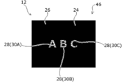
- the character displayed on the decorative panel 10 is "ABC".
- a symbol may be displayed on the decorative panel 10, or both characters and a symbol may be displayed.
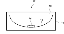
- the display unit 12 includes a housing 16 in which one side is open and the other side is closed, and an LED 14 provided on the closed side in the housing 16. Further, the display unit 12 includes a decorative panel 10 that closes the open side of the housing 16 while being attached to the housing 16.
- the housing 16 is formed in a box shape using a black resin material having a light-shielding property as an example.
- the housing 16 is formed with a concave recess 18.
- the LED 14 is fixed to the bottom of the recess 18.
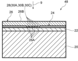
- the decorative panel 10 is laminated on one surface of a base material 20 formed in a plate shape using a colorless and transparent resin material having translucency as an example.
- the first coat layer 22, the light-shielding layer 24, and the second coat layer 26 as a coat layer are provided.
- the first coat layer 22 is formed in the form of a thin sheet using a colorless or colored transparent resin material having translucency as an example.
- the thickness T1 (thickness in the direction facing the base material 20) of the first coat layer 22 is several tens of ⁇ m.
- One surface of the first coat layer 22 is joined to one surface of the base material 20.
- a light-shielding layer 24, which will be described later, is bonded to the other surface of the first coat layer 22.
- the first coat layer 22 functions as an adhesive layer for joining the light-shielding layer 24 to one surface of the base material 20.
- the light-shielding layer 24 may be directly bonded to one surface of the base material 20 without providing the first coat layer 22.
- the light-shielding layer 24 is formed by transferring black ink onto the first coat layer 22 by gravure printing or the like.
- the thickness T2 (thickness in the direction facing the base material 20) of the light-shielding layer 24 is set to 3 to 5 ⁇ m.
- the light-shielding layer 24 is formed with an opening 28 having a predetermined shape by subjecting it to processing such as laser cutting.
- the shape of the opening 28 corresponds to the letter "ABC" shown in FIG.
- the portion of the light-shielding layer 24 corresponding to the character "A" is referred to as a character symbol portion 30A.
- the character symbol portion 30A is formed by a single opening 28A.
- the portion of the light-shielding layer 24 corresponding to the character "B” is referred to as a character symbol portion 30B.
- the character symbol portion 30B is formed by a single opening 28B.
- the portion of the light-shielding layer 24 corresponding to the character "C” is referred to as a character symbol portion 30C.
- the character symbol portion 30C is formed by a single opening 28C.
- the second coat layer 26 is formed by applying paint on the light-shielding layer 24 and the portion of the first coat layer 22 corresponding to the opening 28 of the light-shielding layer 24.
- the second coat layer 26 is formed by using a colorless and transparent paint.
- the thickness T3 (thickness in the direction facing the base material 20) of the second coat layer 26 on the light-shielding layer 24 is about 20 ⁇ m.
- a part 26A of the second coat layer 26 is in a state of entering the inside of the opening 28 of the light shielding layer 24 without a gap.
- the display unit 12 of the present embodiment when the LED 14 in the housing 16 is turned on, the light from the LED 14 is emitted from the base material 20, the first coat layer 22, and the light shielding of the decorative panel 10.
- the outside of the housing 16 is irradiated through the opening 28 of the layer 24 and the second coat layer 26.
- the parts corresponding to the character symbols 30A, 30B, and 30C in the decorative panel 10 are illuminated, and the characters "ABC" are displayed on the decorative panel 10.
- the LED 14 in the housing 16 when the LED 14 in the housing 16 is turned off, the light from the inside of the housing 16 is not emitted from the opening 28 of the light shielding layer 24 in the decorative panel 10.
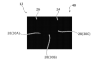
- the portions of the decorative panel 10 corresponding to the character symbols 30A, 30B, and 30C are in a black state, and the entire decorative panel 10 is in a black state (blackout state).
- the thickness T2 (thickness dimension) of the light-shielding layer 24 forming a part of the decorative panel 10 is set to 3 to 5 ⁇ m.
- a step difference in height corresponding to the thickness T2 of the light-shielding layer 24
- the volume of the paint (the paint forming the second coat layer 26) that enters the inside of the opening 28 of the light-shielding layer 24 can be reduced, and the portion of the second coat layer 26 corresponding to the opening 28 of the light-shielding layer 24.
- the thickness T2 (thickness dimension) of the light-shielding layer 24 is set to 10 ⁇ m or less, a step or dent that can be visually visually recognized in a portion of the surface 26B of the second coat layer 26 corresponding to the opening 28 of the light-shielding layer 24. It is known from trial production and the like that this does not occur.
- the light-shielding layer 24 is laminated on the middle coat 34 formed by painting with paint and the middle coat 34. It has a two-layer structure consisting of a transfer layer 36 and a transfer layer 36.
- the members and parts corresponding to the above-mentioned decorative panel 10 are designated by the same reference numerals as the members and parts corresponding to the decorative panel 10.
- the step formed at the edge of the opening 28 of the light-shielding layer 24 is larger than that of the above-mentioned decorative panel 10 because the thickness T4 of the middle coat 34, which is the coating film, is about 20 ⁇ m. growing.
- the surface 26B of the second coat layer 26 it is difficult to prevent the surface 26B of the second coat layer 26 from having a step or a dent in the portion corresponding to the opening 28 of the light-shielding layer 24.
- the light-shielding layer 24 is formed of ink. As a result, it is possible to suppress an increase in the thickness of the light-shielding layer 24 as compared with a structure in which the light-shielding layer 24 is a layer made of paint (the structure of the decorative panel 32 according to the comparative example). .. Further, even when the second coat layer 26 is formed by a paint that easily causes steps or dents depending on the shape of the surface to be applied, the surface of the second coat layer 26 corresponds to the opening 28 of the light shielding layer 24. It is possible to suppress the occurrence of steps and dents in the portion to be covered.
- the light-shielding layer 24 is configured to include a thin-film deposition layer 40 as a metal layer made of a thin-film deposition film.
- the light-shielding layer 24 has a first gravure printing layer 42 formed by gravure printing black ink on the first coating layer 22, and aluminum deposited on the first gravure printing layer 42. It includes a vapor deposition layer 40 formed by the above, and a second gravure printing layer 44 formed by gravure printing black ink on the vapor deposition layer 40.
- the light-shielding layer 24 is formed by being transferred onto the first coat layer 22.
- the first gravure printing layer 42 has a light-shielding property, the light-shielding property is low, and in the present embodiment, the first gravure printing layer 42 functions as an adhesive layer for joining the vapor-deposited layer 40 to one surface of the first coat layer 22.
- the thickness T5 of the first gravure printing layer 42 is set to 1 ⁇ m or less.
- the thin-film deposition layer 40 is a layer having a light transmittance of 10% or less, and is set to a thickness T6 of several ⁇ m as an example.
- the second gravure printing layer 44 is a layer having a light-shielding property, but in the present embodiment, it functions as a decorative layer for making the design of the second decorative panel 38 a predetermined design (pattern).
- the thickness T7 of the second gravure printing layer 44 is set to 3 to 5 ⁇ m or less.
- the thickness of the light-shielding layer 24, which is the sum of these thicknesses T5, T6, and T7, is 10 ⁇ m or less
- the portion of the surface 26B of the second coat layer 26 corresponding to the opening 28 of the light-shielding layer 24 It is possible to suppress the occurrence of steps and dents.
- the light-shielding layer 24 is configured to include the thin-film vapor-deposited layer 40 by the thin-film deposition film, so that the light-shielding property of the light-shielding layer 24 is ensured, and then the design of the decorative panel 38 is provided. Can be the desired design.
- the layer formed by the ink containing the metal pigment may be formed instead of the vapor deposition layer 40.
- the light-shielding layer 24 is configured to include the thin-film deposition layer 40 made of a thin-film deposition film, it does not depend on the pattern of the second gravure printing layer 44 (even if the light-shielding property of the second gravure printing layer 44 is low). The light-shielding property of the light-shielding layer 24 can be ensured without thickening the light-shielding layer 24.
- the opening 28 is formed by removing only a part of the second gravure printing layer 44 of the light shielding layer 24 by processing such as laser cutting. Has been done. As a result, a part of the vapor deposition layer 40 can be visually recognized as the character symbol portions 30A, 30B, and 30C through the opening 28.
- the LED 14 see FIG.
- the metallic luster (metallic luster effect) of the vapor-deposited layer 40 can be obtained in the portions corresponding to the character symbols 30A, 30B, and 30C in the decorative panel 46.
- the design property due to the metallic luster effect can be expressed in the portions corresponding to the character symbol portions 30A, 30B, and 30C.
- the character symbol portions 30A, 30B, and 30C are formed by a plurality of continuous linear openings 28 that intersect in a grid pattern.
- the ratio occupied by the opening 28 in the character symbol portions 30A, 30B, and 30C is defined as the opening ratio.
- the width W of each opening 28 and the distance L1 between the openings 28 are set so that the opening ratio is in the range of 10 to 70%.
- the width W of the openings 28 is set in the range of 15 to 35 ⁇ m, and the interval L1 between the openings 28 is set to an interval of 1.1 to 20 times the width W.
- the character symbols 30A, 30B, and 30C can be visually recognized when the LED 14 (see FIG. 2) is lit as shown in FIG.
- the character symbols 30A, 30B, and 30C can be made invisible.
- the opening ratio is 70% or less.
- the character symbols 30A, 30B, and 30C can be formed in the same manner as the symbol of the light-shielding layer 24. Therefore, when the LED 14 is turned off, the decorative panel 48 has a uniform pattern. Can be done. Although the size of the opening 28 is different between the above-mentioned decorative panel 10 (see FIG. 3) and the decorative panel 48 of the present embodiment, the thickness of the light-shielding layer 24 is 10 ⁇ m or less. As a result, regardless of the difference in the size of the openings 28, the occurrence of steps and dents can be suppressed regardless of the paint forming the second coat layer 26.
- the opening ratio may be adjusted by adjusting the inner diameter D of the plurality of circular openings 28 and the distance L2 between the openings 28.
- the dot-shaped pattern of the plurality of circular openings 28 can be visually recognized. It is known from trial production that it cannot be done.
- the present invention is not limited to the above, and can be modified in various ways other than the above within a range not deviating from the gist thereof. Of course.
Landscapes
- Physics & Mathematics (AREA)
- General Physics & Mathematics (AREA)
- Engineering & Computer Science (AREA)
- Theoretical Computer Science (AREA)
- Illuminated Signs And Luminous Advertising (AREA)
- Laminated Bodies (AREA)
Abstract
加飾パネルは、透光性を有する素材を用いて形成された基材と、基材の一方側の面に沿って設けられた遮光層と、を備えている。遮光層は、遮光性を有する素材を用いて形成されている。また、遮光層には、基材側からの光が通過する開口が形成されている。遮光層の基材と対向する方向への厚み寸法は10μm以下に設定されている。また、加飾パネルは、遮光層上に設けられた第2コート層を備えている。この第2コート層は、透光性を有する素材を用いて形成され、その一部が開口内に配置された状態で遮光層を覆っている。
Description
本発明は、加飾パネル及び表示部に関する。
特開2000-57871号公報には、押釦スイッチ用の部材が開示されている。この押釦スイッチ用の部材は、当該押釦スイッチ用の部材の基材を形成するエラストマー材と、このエラストマー材の一方側の面上に積層された透光性着色層と、エラストマー材の一方側の面上及び透光性着色層上に積層された遮光性着色層と、を備えている。また、遮光性着色層において透光性着色層と対応する部分の一部は、レーザーエッチングで記号状に除去された表示部となっている。このような構成とすることで、エラストマー材側からの光が透光性着色層を通じて表示部から照射される。
ところで、遮光性着色層上にコート層をさらに設ける構成では、コート層において表示部と対応する部分に段差や窪みが生じることが考えられる。
本発明は上記事実を考慮し、コート層の表面に段差や窪みが生じることを抑制することができる加飾パネル及び表示部を得ることが目的である。
第1の態様に係る加飾パネルは、透光性を有する素材を用いて形成された基材と、遮光性を有する素材を用いて形成され、前記基材の一方側の面に沿って設けられていると共に前記基材側からの光が通過する開口が形成され、前記基材と対向する方向への厚み寸法が10μm以下に設定された遮光層と、透光性を有する素材を用いて形成され、前記遮光層上に設けられ、その一部が前記開口内に配置された状態で前記遮光層を覆うコート層と、を備えている。
第2の態様に係る加飾パネルは、透光性を有する素材を用いて形成された基材と、前記基材側が遮光性を有する金属材料を含んで構成された金属層とされていると共に前記基材とは反対側が装飾層とされ、前記基材の一方側の面に沿って設けられていると共に前記基材側からの光が通過する開口が形成された遮光層と、透光性を有する素材を用いて形成され、前記遮光層上に設けられ、その一部が前記開口内に配置された状態で前記遮光層を覆うコート層と、を備えている。
第3の態様に係る加飾パネルは、第2の態様に係る加飾パネルにおいて、前記金属層が、金属製の蒸着膜とされている。
第4の態様に係る加飾パネルは、第1の態様~第3の態様のいずれか態様の加飾パネルにおいて、前記遮光層は、印刷によって形成された層を有しており、前記コート層は、印刷又は塗装によって形成された層となっている。
第5の態様に係る加飾パネルは、第1の態様~第4の態様のいずれか態様の加飾パネルにおいて、前記遮光層には、文字及び図柄の少なくとも一方を示す文字図柄部が複数の前記開口によって形成され、前記文字図柄部において前記開口が占める割合を開口率とした場合に、該開口率が10~70%の範囲に設定されている。
第6の態様に係る加飾パネルは、第5の態様の加飾パネルにおいて、前記文字図柄部は、格子状に交わる複数の前記開口によって形成されている。
第7の態様に係る表示部は、一方側が開放されたハウジングと、前記ハウジング内に設けられた光源と、前記ハウジングに取付けられた状態で該ハウジングにおいて開放された側を閉止する第1の態様~第6の態様のいずれか態様の加飾パネルと、を備えている。
第1の態様に係る加飾パネルでは、遮光層の基材と対向する方向への厚み寸法が10μm以下に設定されている。これにより、遮光層の開口の縁部に生じる段差を抑制することができる。その結果、コート層の表面において遮光層の開口と対応する部分に段差や窪みが生じることを抑制することができる。
第2の態様に係る加飾パネルでは、遮光性の高い金属材料を用いて金属層を形成することで、金属層の厚みを薄くすることができる。これにより、当該金属層を有する遮光層の厚みが増加することを抑制することができ、遮光層の開口の縁部に生じる段差を抑制することができる。その結果、コート層の表面において遮光層の開口と対応する部分に段差や窪みが生じることを抑制することができる。
第3の態様に係る加飾パネルでは、金属層を蒸着膜とすることで、金属層の厚みをより一層薄くすることができる。これにより、蒸着膜である金属層を有する遮光層の厚みが増加することをより一層抑制することができ、遮光層の開口の縁部に生じる段差をより一層抑制することができる。その結果、コート層の表面において遮光層の開口と対応する部分に段差や窪みが生じることをより一層抑制することができる。
第4の態様に係る加飾パネルでは、遮光層が印刷によって形成された層を有している。これにより、当該印刷による層が塗装による層となっている構成と比べて、遮光層の厚みが増加することを抑制することができる。また、塗布される表面の形状等に応じた段差や窪みが生じやすい塗装によってコート層を形成した場合であっても、コート層の表面において遮光層の開口と対応する部分に段差や窪みが生じることを抑制することができる。
第5の態様に係る加飾パネルでは、文字図柄部において開口が占める割合である開口率が、10~70%の範囲に設定されている。これにより、基材側からの光が遮光層の開口を通過しない状態で第5の態様に係る加飾パネルを基材とは反対側から見た際に、文字図柄部と当該文字図柄部以外の部分との境界が視認されることを防止又は抑制することができる。
第6の態様に係る加飾パネルでは、格子状に交わる複数の開口の間隔を調節することにより、開口率を容易に調節することができる。
第7の態様に係る表示部では、ハウジング内の光源が点灯すると、光源からの光が加飾パネルの基材、遮光層の開口及びコート層を通じてハウジングの外側に照射される。ここで、本表示部が、第1の態様~第6の態様のいずれか態様の加飾パネルを含んで構成されていることにより、コート層の表面に段差や窪みが生じることを抑制することができる。
(第1の加飾パネル10及び表示部12の構成)
図1~図3を用いて、本発明の実施形態に係る第1の加飾パネル10及び表示部12の構造について説明する。
図1~図3を用いて、本発明の実施形態に係る第1の加飾パネル10及び表示部12の構造について説明する。
図1及び図2に示されるように、本実施形態の表示部12は、光源としてのLED14が点灯することにより加飾パネル10上に文字を表示させるものである。なお、本実施形態では、加飾パネル10上に表示される文字は「ABC」となっている。なお、加飾パネル10上には、図柄が表示されてもよいし文字と図柄の両方が表示されてもよい。
表示部12は、一方側が開放されていると共に他方側が閉止されたハウジング16と、ハウジング16内における閉止された側に設けられたLED14と、を備えている。また、表示部12は、ハウジング16に取付けられた状態で当該ハウジング16において開放された側を閉止する加飾パネル10と、を備えている。
図2に示されるように、ハウジング16は、一例として遮光性を有する黒色の樹脂材料を用いて箱状に形成されている。このハウジング16には、凹状の凹部18が形成されている。そして、LED14は、この凹部18の底に固定されている。
図3に示されるように、加飾パネル10は、一例として透光性を有する無色透明の樹脂材料を用いて板状に形成された基材20と、基材20の一方側の面に積層された第1コート層22、遮光層24及びコート層としての第2コート層26と、を備えている。
第1コート層22は、一例として透光性を有する無色又は有色透明の樹脂材料を用いて薄肉のシート状に形成されている。この第1コート層22の厚みT1(基材20と対向する方向への厚み)は、数十μmとなっている。第1コート層22の一方側の面は、基材20の一方側の面に接合されている。また、第1コート層22の他方側の面には、後述する遮光層24が接合されている。なお、この構成を言い換えると、第1コート層22は、遮光層24を基材20の一方側の面に接合するための接着層として機能していると言える。なお、第1コート層22を設けずに、遮光層24を基材20の一方側の面に直接接合した構成としてもよい。
遮光層24は、黒色のインキを第1コート層22上にグラビア印刷すること等により転写されて形成されている。この遮光層24の厚みT2(基材20と対向する方向への厚み)は、3~5μmに設定されている。また、遮光層24には、レーザーカット等の加工が施されることにより、所定の形状の開口28が形成されている。この開口28の形状は、図1に示された文字「ABC」と対応している。なお、遮光層24において文字「A」と対応する部分を文字図柄部30Aと呼ぶ。この文字図柄部30Aは、単一の開口28Aによって形成されている。また、遮光層24において文字「B」と対応する部分を文字図柄部30Bと呼ぶ。この文字図柄部30Bは、単一の開口28Bによって形成されている。さらに、遮光層24において文字「C」と対応する部分を文字図柄部30Cと呼ぶ。この文字図柄部30Cは、単一の開口28Cによって形成されている。
第2コート層26は、遮光層24上及び第1コート層22において遮光層24の開口28と対応する部分上に塗料による塗装が施されることにより形成されている。本実施形態では、無色透明の塗料を用いて第2コート層26が形成されている。また、遮光層24上における第2コート層26の厚みT3(基材20と対向する方向への厚み)は、20μm程となっている。さらに、第2コート層26の一部26Aは、遮光層24の開口28の内部に隙間なく入り込んだ状態となっている。
(本実施形態の作用並びに効果)
次に、本実施形態の作用並びに効果について説明する。
次に、本実施形態の作用並びに効果について説明する。
図1及び図2に示されるように、本実施形態の表示部12では、ハウジング16内のLED14が点灯すると、LED14からの光が加飾パネル10の基材20、第1コート層22、遮光層24の開口28及び第2コート層26を通じてハウジング16の外側に照射される。これにより、加飾パネル10において文字図柄部30A、30B、30Cと対応する部分が光った状態となり、文字「ABC」が、加飾パネル10上に表示される。
また、ハウジング16内のLED14が消灯した状態では、ハウジング16内からの光が加飾パネル10における遮光層24の開口28から照射されない状態となる。その結果、加飾パネル10において文字図柄部30A、30B、30Cと対応する部分が黒色の状態となり、加飾パネル10上の全体が黒色の状態(ブラックアウト状態)となる。
ここで、本実施形態の表示部12では、加飾パネル10の一部を構成する遮光層24の厚みT2(厚み寸法)が3~5μmに設定されている。これにより、遮光層24の開口28の縁部に生じる段差(遮光層24の厚みT2と対応する高さの差)を抑制することができる。その結果、遮光層24の開口28の内部に入り込む塗料(第2コート層26を形成する塗料)の体積を少なくすることができ、第2コート層26において遮光層24の開口28と対応する部分にヒケが生じることを抑制することができる。また、第2コート層26の表面26Bにおいて遮光層24の開口28と対応する部分に段差や窪みが生じることを抑制することができる。ここで、遮光層24の厚みT2(厚み寸法)が10μm以下に設定されていれば、第2コート層26の表面26Bにおいて遮光層24の開口28と対応する部分に視覚により視認できる段差や窪みが生じないことが、試作等によりわかっている。
なお、図4に示された比較例に係る加飾パネル32の構成では、遮光層24が、塗料による塗装が施されることにより形成されたミドルコート34と、このミドルコート34上に積層された転写層36と、による2層構造となっている。なお、比較例に係る加飾パネル32において前述の加飾パネル10(図3参照)と対応する部材及び部分には、加飾パネル10と対応する部材及び部分と同じ符号を付している。そして、比較例に係る加飾パネル32では、塗装膜であるミドルコート34の厚みT4が20μm程となることにより遮光層24の開口28の縁部に生じる段差が前述の加飾パネル10よりも大きくなる。その結果、第2コート層26の表面26Bにおいて遮光層24の開口28と対応する部分に段差や窪みが生じることを抑制することが難しくなっている。
以上説明したように、本実施形態では、遮光層24がインキによって形成されている。これにより、遮光層24が塗料による層となっている構成(比較例に係る加飾パネル32の構成)と比べて、遮光層24の厚みが増加することを抑制することが可能となっている。また、塗布される表面の形状等に応じた段差や窪みが生じやすい塗料によって第2コート層26を形成した場合であっても、第2コート層26の表面において遮光層24の開口28と対応する部分に段差や窪みが生じることを抑制することが可能となっている。
(第2の加飾パネル38の構成)
次に、図5を用いて、本発明の実施形態に係る第2の加飾パネル38の構成について説明する。なお、第2の加飾パネル38において前述の加飾パネル10(図3参照)と対応する部材及び部分には、加飾パネル10と対応する部材及び部分と同じ符号を付して、その説明を省略することがある。
次に、図5を用いて、本発明の実施形態に係る第2の加飾パネル38の構成について説明する。なお、第2の加飾パネル38において前述の加飾パネル10(図3参照)と対応する部材及び部分には、加飾パネル10と対応する部材及び部分と同じ符号を付して、その説明を省略することがある。
図5に示されるように、第2の加飾パネル38では、遮光層24が、蒸着膜による金属層としての蒸着層40を含んで構成されている。具体的には、遮光層24は、黒色のインキが第1コート層22上にグラビア印刷されることにより形成された第1グラビア印刷層42と、アルミニウムが第1グラビア印刷層42上に蒸着されることにより形成された蒸着層40と、黒色のインキが蒸着層40上にグラビア印刷されることにより形成された第2グラビア印刷層44と、を備えている。遮光層24は、第1コート層22上に転写されて形成されている。第1グラビア印刷層42は、遮光性を有する層ではあるが遮光性が低く、本実施形態では蒸着層40を第1コート層22の一方側の面に接合するための接着層として機能している。この第1グラビア印刷層42の厚みT5は、1μm以下に設定されている。また、蒸着層40は、透光率が10%以下の層となっており、一例として数μmの厚みT6に設定されている。第2グラビア印刷層44は、遮光性を有する層ではあるが、本実施形態では第2の加飾パネル38の意匠を所定の意匠(柄)とするための装飾層として機能している。この第2グラビア印刷層44の厚みT7は、3~5μm以下に設定されている。そして、これらの厚みT5、T6及びT7を合わせた遮光層24の厚みは、10μm以下となっている。
以上説明した第2の加飾パネル38の構成においても、前述の加飾パネル10(図3参照)と同様に、第2コート層26の表面26Bにおいて遮光層24の開口28と対応する部分に段差や窪みが生じることを抑制することができる。また、第2の加飾パネル38では、遮光層24が、蒸着膜による蒸着層40を含んで構成されていることにより、遮光層24による遮光性を確保した上で、加飾パネル38の意匠を所望の意匠とすることができる。なお、金属顔料を含むインキによって形成された層を蒸着層40に代えて形成してもよい。また、遮光層24が、蒸着膜による蒸着層40を含んで構成されていることにより、第2グラビア印刷層44の柄によらず(第2グラビア印刷層44の遮光性が低くても)、遮光層24を厚くすることなく当該遮光層24による遮光性を確保することができる。
(第3の加飾パネル46の構成)
次に、図6及び図7を用いて、本発明の実施形態に係る第3の加飾パネル46の構成について説明する。なお、第3の加飾パネル46において前述の第2の加飾パネル38(図5参照)と対応する部材及び部分には、加飾パネル38と対応する部材及び部分と同じ符号を付して、その説明を省略することがある。
次に、図6及び図7を用いて、本発明の実施形態に係る第3の加飾パネル46の構成について説明する。なお、第3の加飾パネル46において前述の第2の加飾パネル38(図5参照)と対応する部材及び部分には、加飾パネル38と対応する部材及び部分と同じ符号を付して、その説明を省略することがある。
図6及び図7に示されるように、第3の加飾パネル46では、遮光層24の第2グラビア印刷層44の一部のみがレーザーカット等の加工により除去されることによって開口28が形成されている。これにより、開口28を通じて蒸着層40の一部が文字図柄部30A、30B、30Cとして視認可能となっている。この第3の加飾パネル46では、ハウジング16内のLED14(図2参照)が点灯すると、薄い蒸着層40を光の一部が通過することで、加飾パネル46において文字図柄部30A、30B、30Cと対応する部分が淡く光った状態(第1の加飾パネル10及び第2の加飾パネル38よりも淡く光った状態)となり、文字「ABC」が、加飾パネル46上に淡く表示される。
また、ハウジング16内のLED14が消灯した状態では、加飾パネル46において文字図柄部30A、30B、30Cと対応する部分において蒸着層40の金属光沢(金属光沢効果)を得ることができる。これにより、本実施形態では、文字図柄部30A、30B、30Cと対応する部分において金属光沢効果による意匠性を表現することができる。
(第4の加飾パネル48の構成)
次に、図8~図11を用いて、本発明の実施形態に係る第4の加飾パネル48の構成について説明する。なお、第4の加飾パネル48において前述の加飾パネル10(図3参照)と対応する部材及び部分には、加飾パネル10と対応する部材及び部分と同じ符号を付して、その説明を省略することがある。
次に、図8~図11を用いて、本発明の実施形態に係る第4の加飾パネル48の構成について説明する。なお、第4の加飾パネル48において前述の加飾パネル10(図3参照)と対応する部材及び部分には、加飾パネル10と対応する部材及び部分と同じ符号を付して、その説明を省略することがある。
図8及び図9に示されるように、第4の加飾パネル48では、文字図柄部30A、30B、30Cが、格子状に交わる線状の複数の連続した開口28によって形成されている。ここで、文字図柄部30A、30B、30Cにおいて開口28が占める割合を開口率とする。そして、この開口率が10~70%の範囲となるように各々の開口28の幅W及び開口28間の間隔L1を設定する。ここで、本実施形態では、開口28の幅Wは、15~35μmの範囲に設定され、開口28間の間隔L1は、幅Wの1.1~20倍の間隔に設定されている。当該範囲の開口率に設定することで、図10に示されるようにLED14(図2参照)の点灯時に文字図柄部30A、30B、30Cを視認可能としつつ、図11に示されるようにLED14の消灯時に文字図柄部30A、30B、30Cを視認不能とすることができる。なお、LED14の消灯時に文字図柄部30A、30B、30Cを視認不能とするためには、遮光層24を一様な濃度の黒色とすることが有効である。また、開口率を10%以上に設定することで、図10に示されるようにLED14(図2参照)の点灯時に文字図柄部30A、30B、30Cを視認可能としつつ、開口率を70%以下の設定することで、図11に示されるようにLED14の消灯時に文字図柄部30A、30B、30Cにおいても遮光層24の図柄と同様にできるため、LED14の消灯時に加飾パネル48を均一な柄とできる。なお、前述の加飾パネル10(図3参照)と本実施形態の加飾パネル48では、開口28の大きさが異なっているが、遮光層24の厚みはともに10μm以下となっている。これにより、開口28の大きさの違いによらず、第2コート層26を形成する塗料によらず段差や窪みの発生についても両者ともに抑制することができる。
また、図12に示されるように、円形の複数の開口28の内径Dや開口28間の間隔L2を調節することにより開口率を調節してもよい。なお、円形の複数の開口28の内径Dを0.09mm未満に設定し、開口28間の間隔L2を0.09mm未満に設定することにより、円形の複数の開口28によるドット状の模様が視認できないことが、試作等によりわかっている。また、図13に示されるように、加飾パネル28、46における蒸着膜による蒸着層40を含んで構成された遮光層24に図8~図12に示された構成を適用した加飾パネル50としてもよい。
以上、本発明の一実施形態について説明したが、本発明は、上記に限定されるものでなく、その主旨を逸脱しない範囲内において上記以外にも種々変形して実施することが可能であることは勿論である。
2020年3月23日に出願された日本国特許出願2020-051495号の開示は、その全体が参照により本明細書に取込まれる。
Claims (7)
- 透光性を有する素材を用いて形成された基材と、
遮光性を有する素材を用いて形成され、前記基材の一方側の面に沿って設けられていると共に前記基材側からの光が通過する開口が形成され、前記基材と対向する方向への厚み寸法が10μm以下に設定された遮光層と、
透光性を有する素材を用いて形成され、前記遮光層上に設けられ、その一部が前記開口内に配置された状態で前記遮光層を覆うコート層と、
を備えた加飾パネル。 - 透光性を有する素材を用いて形成された基材と、
前記基材側が遮光性を有する金属材料を含んで構成された金属層とされていると共に前記基材とは反対側が装飾層とされ、前記基材の一方側の面に沿って設けられていると共に前記基材側からの光が通過する開口が形成された遮光層と、
透光性を有する素材を用いて形成され、前記遮光層上に設けられ、その一部が前記開口内に配置された状態で前記遮光層を覆うコート層と、
を備えた加飾パネル。 - 前記金属層が、金属製の蒸着膜とされている請求項2記載の加飾パネル。
- 前記遮光層は、印刷によって形成された層を有しており、
前記コート層は、印刷又は塗装によって形成された層となっている請求項1~請求項3のいずれか1項に記載の加飾パネル。 - 前記遮光層には、文字及び図柄の少なくとも一方を示す文字図柄部が複数の前記開口によって形成され、
前記文字図柄部において前記開口が占める割合を開口率とした場合に、該開口率が10~70%の範囲に設定された請求項1~請求項4のいずれか1項に記載の加飾パネル。 - 前記文字図柄部は、格子状に交わる複数の前記開口によって形成されている請求項5に記載の加飾パネル。
- 一方側が開放されたハウジングと、
前記ハウジング内に設けられた光源と、
前記ハウジングに取付けられた状態で該ハウジングにおいて開放された側を閉止する請求項1~請求項6のいずれか1項に記載の加飾パネルと、
を備えた表示部。
Priority Applications (2)
| Application Number | Priority Date | Filing Date | Title |
|---|---|---|---|
| US17/909,803 US20230326378A1 (en) | 2020-03-23 | 2021-01-27 | Decorative panel and display portion |
| CN202180017117.9A CN115176301A (zh) | 2020-03-23 | 2021-01-27 | 装饰面板以及显示部 |
Applications Claiming Priority (2)
| Application Number | Priority Date | Filing Date | Title |
|---|---|---|---|
| JP2020-051495 | 2020-03-23 | ||
| JP2020051495A JP7320471B2 (ja) | 2020-03-23 | 2020-03-23 | 加飾パネル及び表示部 |
Publications (1)
| Publication Number | Publication Date |
|---|---|
| WO2021192588A1 true WO2021192588A1 (ja) | 2021-09-30 |
Family
ID=77848599
Family Applications (1)
| Application Number | Title | Priority Date | Filing Date |
|---|---|---|---|
| PCT/JP2021/002862 Ceased WO2021192588A1 (ja) | 2020-03-23 | 2021-01-27 | 加飾パネル及び表示部 |
Country Status (4)
| Country | Link |
|---|---|
| US (1) | US20230326378A1 (ja) |
| JP (1) | JP7320471B2 (ja) |
| CN (1) | CN115176301A (ja) |
| WO (1) | WO2021192588A1 (ja) |
Cited By (1)
| Publication number | Priority date | Publication date | Assignee | Title |
|---|---|---|---|---|
| WO2024101436A1 (ja) * | 2022-11-09 | 2024-05-16 | 大日本印刷株式会社 | 加飾表皮材、加飾部材、表示システム、加飾表皮材の製造方法及び加飾部材の製造方法 |
Families Citing this family (3)
| Publication number | Priority date | Publication date | Assignee | Title |
|---|---|---|---|---|
| DE102021200335A1 (de) * | 2021-01-15 | 2022-07-21 | Faurecia Innenraum Systeme Gmbh | Bedieneinheit für einen fahrzeuginnenraum sowie verfahren zum herstellen der bedieneinheit |
| JP7815916B2 (ja) * | 2022-03-25 | 2026-02-18 | 株式会社Jvcケンウッド | 表示装置及び表示装置の製造方法 |
| CN114889535A (zh) * | 2022-04-29 | 2022-08-12 | 苏州恒吴汽车零部件科技有限公司 | 透光装饰板、透光装饰件及其加工工艺 |
Citations (6)
| Publication number | Priority date | Publication date | Assignee | Title |
|---|---|---|---|---|
| JP2001277285A (ja) * | 2000-03-29 | 2001-10-09 | Nissha Printing Co Ltd | 照光性加飾用シートとこれを用いた照光性加飾成形品 |
| US20060044228A1 (en) * | 2004-09-02 | 2006-03-02 | 3M Innovative Properties Company | Substrates with multiple images and methods of use |
| JP2013003489A (ja) * | 2011-06-21 | 2013-01-07 | Tokai Rika Co Ltd | 表示装置 |
| JP2017207578A (ja) * | 2016-05-17 | 2017-11-24 | ウェッジ株式会社 | 照光式表示板及び照光式表示板の製造方法 |
| JP2018163341A (ja) * | 2017-03-24 | 2018-10-18 | 大日本印刷株式会社 | 加飾シート、及び透過型投射システム |
| WO2020196906A1 (ja) * | 2019-03-28 | 2020-10-01 | 大日本印刷株式会社 | 加飾シートの製造方法、加飾シート及び加飾シート付き表示装置 |
Family Cites Families (21)
| Publication number | Priority date | Publication date | Assignee | Title |
|---|---|---|---|---|
| JPH1076745A (ja) * | 1996-09-03 | 1998-03-24 | Toppan Printing Co Ltd | 偽造防止印刷物 |
| JP2008256557A (ja) * | 2007-04-05 | 2008-10-23 | Nissan Motor Co Ltd | 透過照明型メータ |
| US8500348B2 (en) * | 2008-11-24 | 2013-08-06 | Logitech Europe S.A. | Keyboard with ultra-durable keys |
| JP5303365B2 (ja) * | 2009-06-04 | 2013-10-02 | 株式会社ウェーブロック・アドバンスト・テクノロジー | 背光表示パネル、及び、その製造方法 |
| US8451146B2 (en) * | 2010-06-11 | 2013-05-28 | Apple Inc. | Legend highlighting |
| US20120098751A1 (en) * | 2010-10-23 | 2012-04-26 | Sunrex Technology Corp. | Illuminated computer input device |
| JP4967071B1 (ja) * | 2011-10-06 | 2012-07-04 | フジマーク株式会社 | 表示部材及びその作製方法 |
| JP2016532232A (ja) * | 2013-09-30 | 2016-10-13 | アップル インコーポレイテッド | 厚みを薄くしたキーキャップ |
| WO2015047606A1 (en) * | 2013-09-30 | 2015-04-02 | Apple Inc. | Keycaps having reduced thickness |
| KR101666545B1 (ko) * | 2015-09-17 | 2016-10-14 | 최미영 | 전자제품용 스크린 인쇄방법 및 그 전자제품 |
| JP6202079B2 (ja) * | 2015-12-11 | 2017-09-27 | 大日本印刷株式会社 | 通知窓付き表示装置用前面保護板、および表示装置 |
| US10192695B2 (en) * | 2016-08-24 | 2019-01-29 | Getac Technology Corporation | Keyswitch assembly and manufacturing method thereof |
| US10242810B2 (en) * | 2016-12-05 | 2019-03-26 | Intel Corporation | Bi-stable keycap display |
| US10984969B1 (en) * | 2017-07-12 | 2021-04-20 | Apple Inc. | Uniform illumination of keys on a flexible substrate |
| WO2019013114A1 (ja) * | 2017-07-13 | 2019-01-17 | パナソニックIpマネジメント株式会社 | 鏡、及び鏡システム |
| JP6854449B2 (ja) * | 2017-07-13 | 2021-04-07 | パナソニックIpマネジメント株式会社 | 鏡 |
| WO2020040204A1 (ja) * | 2018-08-21 | 2020-02-27 | 大日本印刷株式会社 | 加飾シート及び加飾シート付き表示装置 |
| US11398359B2 (en) * | 2018-12-26 | 2022-07-26 | Apple Inc. | Transparent keycaps |
| CN211555751U (zh) * | 2019-05-20 | 2020-09-22 | 光宝电子(广州)有限公司 | 剪刀件与按键结构 |
| US12198875B2 (en) * | 2021-06-10 | 2025-01-14 | Apple Inc. | One-way visibility keycaps |
| TWI835160B (zh) * | 2022-06-08 | 2024-03-11 | 勤倫股份有限公司 | 熱可塑耐磨塑型膜及其塑型物 |
-
2020
- 2020-03-23 JP JP2020051495A patent/JP7320471B2/ja active Active
-
2021
- 2021-01-27 WO PCT/JP2021/002862 patent/WO2021192588A1/ja not_active Ceased
- 2021-01-27 US US17/909,803 patent/US20230326378A1/en active Pending
- 2021-01-27 CN CN202180017117.9A patent/CN115176301A/zh active Pending
Patent Citations (6)
| Publication number | Priority date | Publication date | Assignee | Title |
|---|---|---|---|---|
| JP2001277285A (ja) * | 2000-03-29 | 2001-10-09 | Nissha Printing Co Ltd | 照光性加飾用シートとこれを用いた照光性加飾成形品 |
| US20060044228A1 (en) * | 2004-09-02 | 2006-03-02 | 3M Innovative Properties Company | Substrates with multiple images and methods of use |
| JP2013003489A (ja) * | 2011-06-21 | 2013-01-07 | Tokai Rika Co Ltd | 表示装置 |
| JP2017207578A (ja) * | 2016-05-17 | 2017-11-24 | ウェッジ株式会社 | 照光式表示板及び照光式表示板の製造方法 |
| JP2018163341A (ja) * | 2017-03-24 | 2018-10-18 | 大日本印刷株式会社 | 加飾シート、及び透過型投射システム |
| WO2020196906A1 (ja) * | 2019-03-28 | 2020-10-01 | 大日本印刷株式会社 | 加飾シートの製造方法、加飾シート及び加飾シート付き表示装置 |
Cited By (1)
| Publication number | Priority date | Publication date | Assignee | Title |
|---|---|---|---|---|
| WO2024101436A1 (ja) * | 2022-11-09 | 2024-05-16 | 大日本印刷株式会社 | 加飾表皮材、加飾部材、表示システム、加飾表皮材の製造方法及び加飾部材の製造方法 |
Also Published As
| Publication number | Publication date |
|---|---|
| JP7320471B2 (ja) | 2023-08-03 |
| CN115176301A (zh) | 2022-10-11 |
| JP2021149052A (ja) | 2021-09-27 |
| US20230326378A1 (en) | 2023-10-12 |
Similar Documents
| Publication | Publication Date | Title |
|---|---|---|
| JP7320471B2 (ja) | 加飾パネル及び表示部 | |
| US8627586B2 (en) | Illuminated trim panels | |
| US10654304B2 (en) | Method for manufacturing panel element | |
| EP2628638B1 (en) | Automotive body element comprising a light source on its inner face | |
| JP7286943B2 (ja) | 加飾フィルムおよび表示装置 | |
| JP2016141355A (ja) | 車両用電波透過カバー | |
| JP2011123186A (ja) | 発色構造及び発色構造を用いた製品 | |
| JP2019107921A (ja) | 加飾部材及び加飾方法 | |
| KR20200051080A (ko) | 하프미러 조명용 패널 및 이를 이용한 하프미러 조명 | |
| JP2020076696A (ja) | 車載レーダー装置用レドーム及びその製造方法 | |
| JP2016078819A (ja) | 装飾部品及び装飾部品ユニット | |
| JP6066624B2 (ja) | 車両用ウインドパネル | |
| US20200124246A1 (en) | Polymeric substrate and a method of providing same | |
| JP2018079705A (ja) | 装飾部品 | |
| JP2008062808A (ja) | 加飾パネル | |
| EP1672609A2 (de) | Mehrschichtiges Kunststoffteil | |
| JP2698154B2 (ja) | キートツプの製造方法 | |
| JP2023147322A (ja) | 車両用外装部品、車両用電飾ユニット及び車両用外装部品の製造方法 | |
| WO2015037082A1 (ja) | 発光装置 | |
| JP6010882B2 (ja) | 表面パネルの作成方法 | |
| KR20200036842A (ko) | 선택적으로 조명가능한 금속으로 보이는 트림 및 그의 제조 방법 | |
| JP5128763B2 (ja) | 発光性表示体及びその製造方法 | |
| JP4647477B2 (ja) | 両面装飾体用の印刷物、その製造方法、及び両面装飾体 | |
| JP6211134B1 (ja) | 照光式表示板及び照光式表示板の製造方法 | |
| JP7331612B2 (ja) | 計器 |
Legal Events
| Date | Code | Title | Description |
|---|---|---|---|
| 121 | Ep: the epo has been informed by wipo that ep was designated in this application |
Ref document number: 21777135 Country of ref document: EP Kind code of ref document: A1 |
|
| NENP | Non-entry into the national phase |
Ref country code: DE |
|
| 122 | Ep: pct application non-entry in european phase |
Ref document number: 21777135 Country of ref document: EP Kind code of ref document: A1 |