WO2021187178A1 - 光ファイバ接続部品及び光ファイバ接続部品の製造方法 - Google Patents
光ファイバ接続部品及び光ファイバ接続部品の製造方法 Download PDFInfo
- Publication number
- WO2021187178A1 WO2021187178A1 PCT/JP2021/008825 JP2021008825W WO2021187178A1 WO 2021187178 A1 WO2021187178 A1 WO 2021187178A1 JP 2021008825 W JP2021008825 W JP 2021008825W WO 2021187178 A1 WO2021187178 A1 WO 2021187178A1
- Authority
- WO
- WIPO (PCT)
- Prior art keywords
- optical fiber
- holding member
- substrate
- glass fibers
- optical
- Prior art date
- Legal status (The legal status is an assumption and is not a legal conclusion. Google has not performed a legal analysis and makes no representation as to the accuracy of the status listed.)
- Ceased
Links
Images




Classifications
-
- G—PHYSICS
- G02—OPTICS
- G02B—OPTICAL ELEMENTS, SYSTEMS OR APPARATUS
- G02B6/00—Light guides; Structural details of arrangements comprising light guides and other optical elements, e.g. couplings
- G02B6/24—Coupling light guides
- G02B6/36—Mechanical coupling means
- G02B6/38—Mechanical coupling means having fibre to fibre mating means
- G02B6/3807—Dismountable connectors, i.e. comprising plugs
- G02B6/3873—Connectors using guide surfaces for aligning ferrule ends, e.g. tubes, sleeves, V-grooves, rods, pins, balls
- G02B6/3885—Multicore or multichannel optical connectors, i.e. one single ferrule containing more than one fibre, e.g. ribbon type
-
- G—PHYSICS
- G02—OPTICS
- G02B—OPTICAL ELEMENTS, SYSTEMS OR APPARATUS
- G02B6/00—Light guides; Structural details of arrangements comprising light guides and other optical elements, e.g. couplings
- G02B6/02—Optical fibres with cladding with or without a coating
- G02B6/02042—Multicore optical fibres
-
- G—PHYSICS
- G02—OPTICS
- G02B—OPTICAL ELEMENTS, SYSTEMS OR APPARATUS
- G02B6/00—Light guides; Structural details of arrangements comprising light guides and other optical elements, e.g. couplings
- G02B6/02—Optical fibres with cladding with or without a coating
- G02B6/024—Optical fibres with cladding with or without a coating with polarisation maintaining properties
-
- G—PHYSICS
- G02—OPTICS
- G02B—OPTICAL ELEMENTS, SYSTEMS OR APPARATUS
- G02B6/00—Light guides; Structural details of arrangements comprising light guides and other optical elements, e.g. couplings
- G02B6/24—Coupling light guides
- G02B6/36—Mechanical coupling means
- G02B6/3628—Mechanical coupling means for mounting fibres to supporting carriers
- G02B6/3648—Supporting carriers of a microbench type, i.e. with micromachined additional mechanical structures
- G02B6/3652—Supporting carriers of a microbench type, i.e. with micromachined additional mechanical structures the additional structures being prepositioning mounting areas, allowing only movement in one dimension, e.g. grooves, trenches or vias in the microbench surface, i.e. self aligning supporting carriers
-
- G—PHYSICS
- G02—OPTICS
- G02B—OPTICAL ELEMENTS, SYSTEMS OR APPARATUS
- G02B6/00—Light guides; Structural details of arrangements comprising light guides and other optical elements, e.g. couplings
- G02B6/24—Coupling light guides
- G02B6/36—Mechanical coupling means
- G02B6/38—Mechanical coupling means having fibre to fibre mating means
- G02B6/3807—Dismountable connectors, i.e. comprising plugs
- G02B6/381—Dismountable connectors, i.e. comprising plugs of the ferrule type, e.g. fibre ends embedded in ferrules, connecting a pair of fibres
- G02B6/3825—Dismountable connectors, i.e. comprising plugs of the ferrule type, e.g. fibre ends embedded in ferrules, connecting a pair of fibres with an intermediate part, e.g. adapter, receptacle, linking two plugs
-
- G—PHYSICS
- G02—OPTICS
- G02B—OPTICAL ELEMENTS, SYSTEMS OR APPARATUS
- G02B6/00—Light guides; Structural details of arrangements comprising light guides and other optical elements, e.g. couplings
- G02B6/24—Coupling light guides
- G02B6/36—Mechanical coupling means
- G02B6/38—Mechanical coupling means having fibre to fibre mating means
- G02B6/3807—Dismountable connectors, i.e. comprising plugs
- G02B6/3833—Details of mounting fibres in ferrules; Assembly methods; Manufacture
- G02B6/3855—Details of mounting fibres in ferrules; Assembly methods; Manufacture characterised by the method of anchoring or fixing the fibre within the ferrule
- G02B6/3861—Adhesive bonding
-
- G—PHYSICS
- G02—OPTICS
- G02B—OPTICAL ELEMENTS, SYSTEMS OR APPARATUS
- G02B6/00—Light guides; Structural details of arrangements comprising light guides and other optical elements, e.g. couplings
- G02B6/24—Coupling light guides
- G02B6/36—Mechanical coupling means
- G02B6/38—Mechanical coupling means having fibre to fibre mating means
- G02B6/3807—Dismountable connectors, i.e. comprising plugs
- G02B6/3897—Connectors fixed to housings, casing, frames or circuit boards
Definitions
- the present disclosure relates to an optical fiber connection component and a method for manufacturing the optical fiber connection component.
- This application claims priority based on Japanese Application No. 2020-545286 filed on March 16, 2020, and incorporates all the contents described in the Japanese application.
- Patent Document 1 discloses a method for manufacturing an optical connector including a multi-core fiber. According to the manufacturing method disclosed in Patent Document 1, after the multi-core fiber is arranged in the V-groove provided in the connector ferrule, the orientation around the central axis of the multi-core fiber is adjusted (that is, the multi-core fiber is rotationally aligned). Will be done.
- the method for manufacturing an optical fiber connecting component is a glass fiber having a core and a clad covering the core, and has a structure that is not axially symmetric with respect to the central axis in a cross section perpendicular to the central axis of the glass fiber.
- the step of polishing the end face of one or more glass fibers and the end face of the second optical fiber holding member is included.
- the optical fiber connection component of one aspect of the present disclosure is a glass fiber having a core and a clad covering the core, and has a structure that is not axially symmetric with respect to the central axis in a cross section perpendicular to the central axis of the glass fiber. And one or more optical fibers having a resin coating portion covering the glass fiber and the end portion of the glass fiber exposed from the resin coating portion, and a first optical fiber holding member, which is exposed from the resin coating portion.
- a first optical fiber holding member for holding one or more glass fibers and a first optical fiber so that one or more glass fibers are arranged in the first direction and project outward from the first optical fiber holding member.
- It includes a second optical fiber holding member that holds the one or more glass fibers so that the one or more glass fibers protruding from the fiber holding member are arranged in the first direction.
- the end face of the second optical fiber holding member is flush with the end face of one or more glass fibers.
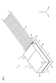
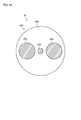
- FIG. 1 It is a perspective view which shows the optical fiber connection component which concerns on 1st Embodiment of this disclosure. It is sectional drawing which shows an example of the glass fiber included in the optical fiber connection component of this disclosure. It is a flowchart for demonstrating the manufacturing method of the optical fiber connection component which concerns on this disclosure. It is a perspective view which shows the state which a plurality of optical fibers are mounted on the 1st substrate in the 1st mounting process in the manufacturing method of the optical fiber connection component which concerns on this disclosure. It is sectional drawing which was cut along the VV line shown in FIG. It is a perspective view which shows the state which each glass fiber is held by the 1st optical fiber holding member in the 1st mounting process in the manufacturing method of the optical fiber connection component which concerns on this disclosure.
- FIG. 6 is a cross-sectional view taken along the line VIIA-VIIA shown in FIG. 6 showing a state in which each glass fiber is adhered to a first substrate and a first lid portion by a first adhesive.
- FIG. 7 is a cross-sectional view of a glass fiber cut along the VIIB-VIIB line shown in FIG. 7A, a first substrate, and a first lid portion. It is a perspective view which shows the state which each glass fiber protruding from the 1st optical fiber holding member is mounted on the 2nd substrate in the 2nd mounting process in the manufacturing method of the optical fiber connection component which concerns on this disclosure.
- the multi-core fiber and the connector ferrule are fixed by an adhesive after the multi-core fiber is rotationally aligned. Then, the end face of the multi-core fiber protruding from the connector ferrule is polished so that the end face of the multi-core fiber and the end face of the connector ferrule are flush with each other.
- the position of the core of the multi-core fiber often fluctuates along the longitudinal direction of the multi-core fiber.
- the position of the core on the end face of the multi-core fiber after the polishing step of the multi-core fiber varies from the position of the core on the end face of the multi-core fiber observed in the rotational alignment step according to the amount of polishing of the end face of the multi-core fiber.
- the position of the core on the end face of the multi-core fiber in the manufactured optical connector deviates from the desired position adjusted in the rotational alignment process, and the coupling between the optical connector and an external optical component such as an optical waveguide circuit There is a risk that the loss will increase.
- a glass fiber having a core and a clad covering the core having a structure not axially symmetric with respect to the central axis in a cross section perpendicular to the central axis of the glass fiber, and a resin coating portion covering the glass fiber.
- a step of preparing one or more optical fibers whose end portions of the glass fibers are exposed from the resin coating portion, and one or more glass fibers exposed from the resin coating portion are arranged in the first direction.
- a rotational alignment step to adjust, a first bonding step of adhering one or more glass fibers to the first optical fiber holding member using a first adhesive, and one or more protruding outward from the first optical fiber holding member.
- a second mounting process in which one or more glass fibers are mounted on the second optical fiber holding member so that the plurality of glass fibers are arranged in the first direction, and one or more glass fibers using a second adhesive. And the end face of one or more glass fibers so that the end face of one or more glass fibers is flush with the end face of the second glass fiber holding member.
- a method for manufacturing an optical fiber connecting component which comprises a step of polishing an end face of a second optical fiber holding member.
- the above manufacturing method it is possible to reduce the amount of polishing of the end face of each glass fiber. Therefore, even when the position of the core of the glass fiber fluctuates along the longitudinal direction of the glass fiber, the position of the core on the end face of the glass fiber at the time when the polishing of the end face of the glass fiber is completed is optical. It does not fluctuate significantly from the position of the core on the end face of the glass fiber observed immediately after the fiber rotation centering process. Therefore, it is possible to prevent a situation in which the coupling loss between the optical fiber connecting component and the external optical component (for example, an optical waveguide circuit) increases.
- the optical fiber connecting component and the external optical component for example, an optical waveguide circuit
- the strength of the optical fiber connecting component can be increased.
- the first optical fiber holding member includes a first substrate having one or a plurality of first grooves, each of which holds a corresponding one of the one or a plurality of glass fibers, and the one or a plurality of glass fibers.
- the second optical fiber holding member includes one or more second groove portions each including a first lid portion facing the first substrate via the glass fiber, and each holding a corresponding one or a plurality of glass fibers.
- the first mounting step includes a second substrate having a second substrate and a second lid portion facing the second substrate via one or more glass fibers, and the first mounting step is one or more glass fibers exposed from the resin coating portion.
- the first bonding step comprises providing the first adhesive in the one or more first grooves so that the one or more glass fibers are bonded to the first substrate and the first lid.
- the mounting process said that the one or more glass fibers were held in the corresponding one of the one or more second grooves so that each of the one or more glass fibers projecting outward from the first substrate was held in the corresponding one or more second grooves.
- the second bonding step comprises mounting the second substrate on the second substrate, and the second bonding step applies the second adhesive to the second substrate and the second lid so that the glass fibers are bonded to the second substrate and the second lid.
- the step of polishing including providing in the groove, is the end face of the glass fiber so that the end face of the glass fiber is flush with the end face of the second substrate and the end face of the second lid.
- the optical fibers can be easily mounted on the first optical fiber holding member and can be arranged with high accuracy on the first optical fiber holding member.
- the second lid portion faces the first substrate and the second substrate, and in the second bonding step, the second substrate is fixed to the first substrate via the second lid portion.
- the first substrate and the second substrate can be indirectly fixed to each other without providing a step of directly adhering the first substrate and the second substrate with an adhesive.
- the first optical fiber holding member includes a first hole capillary having one or more first holes each holding one or more glass fibers, and the second optical fiber holding member is one each.
- the number of parts can be reduced and the man-hours for assembly can be reduced.
- the step of separating each optical fiber can be omitted by mounting the portion of the intermittent adhesive fiber ribbon in which the optical fiber is not integrated on the first optical fiber holding member.
- the step of separating each optical fiber can be omitted.
- each of the one or a plurality of optical fibers is a multi-core fiber having a plurality of cores.
- an optical fiber connection component capable of connecting one or more multi-core fibers with low loss.
- an optical fiber connection component capable of connecting one or more polarization-holding fibers with low crosstalk.
- a glass fiber having a core and a clad covering the core having a structure not axially symmetric with respect to the central axis in a cross section perpendicular to the central axis of the glass fiber, and a resin coating portion covering the glass fiber.
- One or more optical fibers whose ends of the glass fibers are exposed from the resin coating and one or more so that the one or more glass fibers exposed from the resin coating are arranged in the first direction.
- a first optical fiber holding member that holds the glass fibers of the above, and a second that holds the one or more glass fibers so that the one or more glass fibers protruding from the first optical fiber holding member are arranged in the first direction.
- An optical fiber connecting component comprising an optical fiber holding member, wherein the end face of the second optical fiber holding member is flush with the end faces of one or more glass fibers.
- the end face of each glass fiber protruding outward from the first optical fiber holding member since one or more glass fibers protruding from the first optical fiber holding member are held by the second optical fiber holding member, the end face of each glass fiber protruding outward from the first optical fiber holding member. It is possible to reduce the amount of polishing. Therefore, it is possible to prevent a situation in which the position of the core on the end face of the glass fiber of the manufactured optical fiber connecting component deviates from the desired position adjusted in the rotational alignment process. It is possible to prevent a situation in which the coupling loss with an external optical component (for example, an optical waveguide circuit) is increased. In this way, it is possible to improve the optical characteristics of the optical fiber connection component.
- an external optical component for example, an optical waveguide circuit
- the strength of the optical fiber connecting component can be increased.
- the first optical fiber holding member is provided via a first substrate having one or a plurality of first grooves, each of which holds a corresponding one or a plurality of glass fibers, and one or a plurality of glass fibers.
- the second optical fiber holding member includes one or more second grooves, each of which holds a corresponding one of one or more glass fibers.
- the optical fiber connection component according to item (10) or item (11), comprising a second substrate and a second lid portion facing the second substrate via one or more glass fibers.
- the glass fibers exposed from the resin coating can be held by the first substrate and the first lid so as to be arranged in the first direction, and the first substrate and the second lid can hold the glass fibers so as to be arranged in the first direction.
- the glass fibers protruding from the substrate can be held so as to be arranged in the first direction.
- One or a plurality of optical fibers are a plurality of optical fibers, and a plurality of first grooves are arranged in parallel with each other and each is exposed at an end portion of each of the plurality of optical fibers.
- a plurality of first grooves holding the corresponding one of the glass fibers, the one or more second grooves being arranged parallel to each other and each holding the corresponding one of the plurality of glass fibers.
- a plurality of optical fibers can be arranged in the first direction by the plurality of first grooves, and a plurality of optical fibers can be arranged in the first direction by the plurality of second grooves.
- the strength of the optical fiber connection component can be increased.
- the first optical fiber holding member includes a first hole capillary having one or more first holes, each of which holds one or more corresponding ones of glass fibers, and a second optical fiber holding member.
- the glass fibers exposed from the resin coating portion can be held by the first hole capillary so as to be arranged in the first direction, and the glass fibers protruding from the first hole capillary can be held by the second hole capillary. It can be held so as to be arranged in the first direction.
- One or a plurality of optical fibers are a plurality of optical fibers, and a plurality of first holes are arranged in parallel with each other and each is exposed at an end portion of each of the plurality of optical fibers.
- a plurality of first holes holding the corresponding one of the glass fibers, one or more of the second holes being arranged parallel to each other and each holding the corresponding one of the plurality of glass fibers.
- a plurality of optical fibers can be arranged in the first direction by the plurality of first holes, and a plurality of optical fibers can be arranged in the first direction by the plurality of second holes. ..
- the optical fiber connection component 1 functions as an optical fiber array including a plurality of optical fibers 2.
- the optical fiber connecting component 1 functions as an optical connector.
- FIG. 1 is a perspective view showing an optical fiber connection component 1 according to the first embodiment.
- the optical fiber connection component 1 is a first optical fiber that holds a plurality of optical fibers 2 (12 optical fibers 2 in the first embodiment) arranged in the X-axis direction (first direction) and a plurality of optical fibers 2.
- a fiber holding member 3 and a second optical fiber holding member 6 for holding the glass fibers 20 of a plurality of optical fibers 2 are provided.
- each optical fiber 2 is arranged in the X-axis direction while being separated from each other. As shown in FIG. 2, each optical fiber 2 has a structure that is not axisymmetric with respect to the central axis in a cross section perpendicular to the central axis (not shown) extending in the longitudinal direction of the optical fiber 2. Therefore, it is necessary to perform rotational alignment for each optical fiber 2.
- each optical fiber 2 is a multi-core fiber having a plurality of cores 24.
- Each optical fiber 2 has a glass fiber 20 and a resin coating portion 21 that covers the glass fiber 20.
- the glass fiber 20 has a plurality of cores 24 through which signal light propagates, a marker 25, and a clad 23 that covers the plurality of cores 24 and the marker 25.
- the refractive index of each core 24 is larger than that of the clad 23.
- the refractive index of the marker 25 is different from that of the clad 23.
- the marker 25 is used in the rotational alignment step of the optical fiber 2 described later.
- the first optical fiber holding member 3 holds a plurality of glass fibers 20 so that the plurality of glass fibers 20 exposed from the resin coating portion 21 are arranged in the X-axis direction.
- the first optical fiber holding member 3 has a first substrate 4 and a first lid portion 5 facing the first substrate 4 via a plurality of glass fibers 20.
- the first substrate 4 has a holding region 43 for holding the resin coating portion 21 and a holding region 44 for holding each glass fiber 20 exposed from the resin coating portion.
- the holding region 44 is provided with a plurality of first groove portions 46 (see FIG. 4) having a V-shaped cross section for holding one of the corresponding glass fibers 20.
- the second optical fiber holding member 6 holds the plurality of glass fibers 20 so that the plurality of glass fibers 20 protruding from the first optical fiber holding member 3 in the Z-axis direction are arranged in the X-axis direction.
- the second optical fiber holding member 6 has a second substrate 7 and a second lid portion 8 facing the second substrate 7 via a plurality of glass fibers 20.
- the second substrate 7 is provided with a plurality of second groove portions 76 (see FIG. 8) having a V-shaped cross section, each holding one of the corresponding glass fibers 20.
- the second optical fiber holding member 6 is fixed to the first optical fiber holding member 3 via an adhesive.
- the second substrate 7 is fixed to the first substrate 4 via an adhesive
- the second lid portion 8 is fixed to the first lid portion 5 via an adhesive.
- the end face of the second optical fiber holding member 6 is flush with the end face 22 of each glass fiber 20.
- the end surface 72 of the second substrate 7 and the end surface 82 of the second lid portion 8 are flush with the end surface 22 of each glass fiber 20.
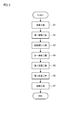
- FIG. 3 is a flowchart for explaining the manufacturing method of the optical fiber connection component 1 according to the present disclosure.
- the preparation step S1 a plurality of optical fibers 2 in which the end portion of the glass fiber 20 is exposed from the resin coating portion 21 are prepared.
- the plurality of optical fibers 2 are not adhered to each other, it is not necessary to separately provide a step of separating each optical fiber 2. Further, the end portion of each glass fiber 20 can be exposed from the resin coating portion 21 by using a predetermined tool.
- a plurality of optical fibers 2 are mounted on the first optical fiber holding member 3.
- each optical fiber 2 is arranged so that the glass fibers 20 exposed from the resin coating portion 21 are arranged in the X-axis direction and project outward from the first substrate 4 in the Z-axis direction. 1 It is mounted on the substrate 4.
- the resin coating portion 21 is held in the holding region 43 of the first substrate 4, and each of the plurality of glass fibers 20 exposed from the resin coating portion 21 is in the holding region 44 of the first substrate 4. It is held in the corresponding one of the grooves 46 (see FIG. 5).
- the orientation (rotational position) around the central axis of each optical fiber 2 is adjusted (that is, the rotational alignment of each optical fiber 2 is performed).
- the surface of each glass fiber 20 protruding from the first optical fiber holding member 3 may be imaged by a camera (not shown).
- the rotation centering device (not shown) may automatically adjust the rotation position of each glass fiber 20 based on the captured image showing the surface of the glass fiber 20 acquired by the camera.
- the rotational position of the glass fiber 20 may be adjusted so that the rotational position of the marker 25 (see FIG. 2) of the glass fiber 20 coincides with a predetermined rotational position. In this way, the rotational positions of the plurality of cores 24 are adjusted to desired rotational positions through the rotational alignment step of the optical fiber 2.
- the first bonding step S4 a plurality of glass fibers 20 are bonded to the first optical fiber holding member 3 using an ultraviolet curable resin (an example of the first adhesive).
- an ultraviolet curable resin an example of the first adhesive.
- the first lid portion 5 is arranged on the holding region 44 of the first substrate 4 via each glass fiber 20. (See FIG. 6).
- the ultraviolet curable resin is attached to the first groove portion 46, the first substrate 4, and the first lid portion 5. It is introduced into the gap between them (see FIGS. 7A and 7B).
- the ultraviolet curable resin may be poured into the gap between the first lid portion 5 and the first substrate 4 from the holding region 43 side. After that, the ultraviolet curable resin is cured by irradiating the ultraviolet curable resin with ultraviolet rays. In this way, each glass fiber 20 is adhered to the first substrate 4 and the first lid portion 5 by the ultraviolet curable resin.
- each optical fiber 2 is mounted on the second substrate 7 so that the glass fibers 20 protruding from the first optical fiber holding member 3 are arranged in the X-axis direction.
- each of the plurality of glass fibers 20 is held by the corresponding one of the plurality of second groove portions 76 in the second substrate 7.
- the tip of each glass fiber 20 slightly protrudes from the end surface 72 of the second substrate 7 in the Z-axis direction.
- the second substrate 7 is adhered to the first substrate 4 via an adhesive.
- a plurality of glass fibers 20 are bonded to the second optical fiber holding member 6 using an ultraviolet curable resin (an example of the second adhesive).
- an ultraviolet curable resin an example of the second adhesive.
- the second lid portion 8 is arranged on the second substrate 7 via each glass fiber 20.
- the ultraviolet curable resin is attached to the second groove portion 76, the second substrate 7, and the second lid portion 8. Introduced in the gap between.
- the ultraviolet curable resin may be poured into the gap between the second lid portion 8 and the second substrate 7 from the end surface 22 side of each glass fiber 20.
- the ultraviolet curable resin is cured by irradiating the ultraviolet curable resin with ultraviolet rays.
- each glass fiber 20 is adhered to the second substrate 7 and the second lid portion 8 by the ultraviolet curable resin.
- the second lid portion 8 is adhered to the first lid portion 5 via an adhesive.
- the end faces 22 of the plurality of glass fibers 20 and the end faces of the second optical fiber holding member 6 are polished. Specifically, the end face 22 of each glass fiber 20 and the end face 22 of each glass fiber 20 are flush with each other so that the end face 22 of each glass fiber 20, the end face 72 of the second substrate 7, and the end face 82 of the second lid portion 8 are flush with each other.
- the end surface 72 of the 2 substrate 7 and the end surface 82 of the second lid portion 8 are polished.
- the amount of protrusion of the glass fiber 20 protruding from the end surface 72 of the second substrate 7 and the end surface 82 of the second lid portion 8 in the Z-axis direction is D2 (mm)
- the glass fiber is D2 or more. In this way, the optical fiber connection component 1 as shown in FIG. 1 is manufactured through the polishing step S7.
- the rotational position of the core 24 above does not change significantly from the rotational position of the core 24 on the end face 22 of the glass fiber 20 observed by the rotational alignment of the optical fiber 2.
- the rotation position of the core 24 on the end face 22 of the glass fiber 20 of the optical fiber connection component 1 manufactured through the polishing process of the glass fiber 20 deviates from the desired position adjusted in the rotation alignment process. Can be prevented. Therefore, it is possible to prevent a situation in which the coupling loss between the optical fiber connecting component 1 and the external optical component (optical waveguide circuit or another optical fiber) increases. In this way, it is possible to improve the optical characteristics of the optical fiber connecting component 1 through the manufacturing method of the optical fiber connecting component 1 according to the first embodiment. Further, according to the first embodiment, since the first optical fiber holding member 3 and the second optical fiber holding member 6 are fixed to each other via an adhesive, the strength of the optical fiber connecting component 1 can be ensured. ..
- each glass fiber 20 and the first optical fiber holding member 3 are bonded to each other by using an ultraviolet curable resin as an example of the adhesive, and each glass fiber 20 and the second optical fiber holding member 6 are attached.
- the first embodiment should not be limited to this.
- a thermosetting resin may be used instead of the ultraviolet curable resin.
- the optical fiber connection component 1 includes 12 optical fibers 2, but the number of optical fibers 2 mounted on the optical fiber connection component 1 is not particularly limited. For example, the number of optical fibers 2 mounted on the optical fiber connection component 1 may be one.
- FIG. 11 is a diagram for explaining a method of manufacturing the optical fiber connection component 1A according to the second embodiment.
- FIG. 12 is a perspective view showing the optical fiber connection component 1A.
- the optical fiber connection component 1A according to the second embodiment is different from the optical fiber connection component 1 according to the first embodiment in that the outer sizes of the first lid portion 5A and the second lid portion 8A are different. It's different.
- the differences between the optical fiber connection component 1 according to the first embodiment and the optical fiber connection component 1A according to the second embodiment will be mainly described.
- the components having the same reference numbers as the components described in the first embodiment will not be repeatedly described.
- the optical fiber connecting component 1A includes a plurality of optical fibers 2, a first optical fiber holding member 3A, and a second optical fiber holding member 6A.
- the first optical fiber holding member 3A has a first substrate 4 and a first lid portion 5A facing the first substrate 4 via each glass fiber 20.
- the outer size of the first lid portion 5A in the Z-axis direction is smaller than the outer size of the first lid portion 5 of the first embodiment in the Z-axis direction.
- the second optical fiber holding member 6A has a second substrate 7 and a second lid portion 8A facing the first substrate 4 and the second substrate 7 via each glass fiber 20.
- the outer size of the second lid 8A in the Z-axis direction is larger than the outer size of the second lid 8 in the first embodiment in the Z-axis direction.
- a part of the second lid portion 8A is adhered to each glass fiber 20 and the first substrate 4 by an ultraviolet curable resin, and another part of the second lid portion 8A is adhered to each glass fiber 20 by an ultraviolet curable resin. And is adhered to the second substrate 7.
- the strength of the optical fiber connection component 1A is increased. be able to.
- each glass fiber 20 is bonded to the first optical fiber holding member 3A using an ultraviolet curable resin (first bonding step S4).
- first bonding step S4 the first lid portion 5A is arranged on the holding region 44 of the first substrate 4 via each glass fiber 20 (see FIG. 11).
- the ultraviolet curable resin is attached to the first groove portion 46, the first substrate 4, and the first lid portion 5A. Introduced in the gap between. After that, the ultraviolet curable resin is cured by irradiating the ultraviolet curable resin with ultraviolet rays. In this way, each glass fiber 20 is adhered to the first substrate 4 and the first lid portion 5A by the ultraviolet curable resin.
- a plurality of glass fibers 20 projecting outward from the first optical fiber holding member 3A in the Z-axis direction are mounted on the second optical fiber holding member 6A.
- the plurality of glass fibers 20 are bonded to the second optical fiber holding member 6A using the ultraviolet curable resin.
- a part of the second lid portion 8A is mounted on the first substrate 4 via each glass fiber 20, and the remaining part of the second lid portion 8A attaches each glass fiber 20. It is mounted on the second substrate 7 via.
- the ultraviolet curable resin is attached to the gap between the second substrate 7 and the second lid portion 8A and the first substrate 4. It is introduced into the gap between the second lid portion 8A and the second lid portion 8A.
- the ultraviolet curable resin is poured from the end surface 22 side of each glass fiber 20 into the gap between the second lid portion 8A and the second substrate 7 and the gap between the second lid portion 8A and the first substrate 4. May be good. After that, the ultraviolet curable resin is cured by irradiating the ultraviolet curable resin with ultraviolet rays. In this way, each glass fiber 20 is adhered to the second substrate 7, the second lid portion 8A, and the first substrate 4 by the ultraviolet curable resin.
- the polishing step S7 the end face 22 of each glass fiber 20 and the end face of the second optical fiber holding member 6A are polished. At this point, the end face 22 of each glass fiber 20 and the second The end face 72 of the substrate 7 and the end face 82A of the second lid portion 8A are polished.
- the first optical fiber holding member 3A and the second optical fiber holding member 6A can be indirectly fixed to each other without providing a step of directly bonding the 3A and the second optical fiber holding member 6A.
- FIG. 13A is a diagram showing a first optical fiber holding member 3B according to a modified example.
- FIG. 13B is a diagram showing a second optical fiber holding member 6B according to a modified example.
- the first optical fiber holding member 3B may be used for the optical fiber connecting component 1 instead of the first optical fiber holding member 3 according to the first embodiment.
- the first optical fiber holding member 3B is a first hole capillary having a plurality of first hole portions 3b arranged in the X-axis direction. Each of the plurality of glass fibers 20 is inserted into the corresponding one of the plurality of first hole portions 3b. As described above, each of the plurality of first hole portions 3b holds the corresponding one of the plurality of glass fibers 20.
- the second optical fiber holding member 6B may be used for the optical fiber connecting component 1.
- the second optical fiber holding member 6B is a second hole capillary having a plurality of second hole portions 6b arranged in the X-axis direction.
- Each of the plurality of glass fibers 20 projecting from the first optical fiber holding member 3B in the Z-axis direction is inserted into the corresponding one of the plurality of second hole portions 6b.
- each of the plurality of second hole portions 6b holds the corresponding one of the plurality of glass fibers 20 protruding from the first optical fiber holding member 3B.
- each optical fiber 2 is mounted on the first optical fiber holding member 3B by inserting each glass fiber 20 into the corresponding one of the plurality of first hole portions 3b.
- each glass fiber 20 is bonded to the first optical fiber holding member 3B by the ultraviolet curable resin (first bonding step S4).
- each glass fiber 20 protruding from the first optical fiber holding member 3B is inserted into the corresponding one of the plurality of second hole portions 6b, so that each glass fiber 20 is second. It is mounted on the optical fiber holding member 6B.
- the second bonding step S6 after each glass fiber 20 is bonded to the second optical fiber holding member 6B by the ultraviolet curable resin, the end face of the second optical fiber holding member 6B and the end face 22 of each glass fiber 20 are attached. Be polished.
- the amount of polishing of each glass fiber 20 can be reduced, so that the rotation position of the core of the optical fiber connection component 1 manufactured through the polishing process of the glass fiber 20 is adjusted by the rotation alignment process. It is possible to prevent a situation in which the desired rotation position is deviated. As described above, it is possible to provide a method for manufacturing the optical fiber connection component 1 capable of improving the optical characteristics of the optical fiber connection component 1.
- the optical fiber is a multi-core fiber having a plurality of cores, but the optical fiber is not limited to the multi-core fiber.
- the structure of the optical fiber is not particularly limited as long as the glass fiber of the optical fiber has a structure that is not axisymmetric with respect to its central axis.
- the polarization-retaining fiber 2A may be applied to the optical fiber connection component 1 instead of the optical fiber 2.
- the polarization-retaining fiber 2A has a glass fiber 20A and a resin coating portion (not shown) covering the glass fiber 20A.
- the glass fiber 20A is arranged between the pair of stress applying portions 26A and the pair of stress applying portions 26A, and has a core 24A through which signal light propagates, a pair of stress applying portions 26A, and a clad 23A covering the core 24A. You may have.
- the polarization-retaining fiber 2A is applied to the optical fiber connection component instead of the optical fiber 2, it is possible to provide an optical fiber connection component capable of connecting the polarization-retaining fiber with low crosstalk.
- the plurality of optical fibers are a plurality of single-core optical fibers that are not bonded to each other, but the present invention is not limited to this.
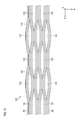
- a plurality of optical fibers 2B included in the intermittent adhesive fiber ribbon 120 may be applied to the optical fiber connecting component 1 instead of the optical fiber 2.
- a non-bonded region 122 which is a region where adjacent optical fibers 2B are not bonded, is intermittently provided along the Z-axis direction.
- the intermittent adhesive fiber ribbon is an intermittent adhesive type in which completely separated regions in which each optical fiber is completely separated from each other and adhesive regions in which each optical fiber is adhered to each other are alternately provided in the Z-axis direction (longitudinal direction). It may be a fiber ribbon. In this case, it is not necessary to separately provide a step of separating each optical fiber before the step of mounting each optical fiber on the first optical fiber holding member.
- the first optical fiber holding member and the second optical fiber holding member need only be able to hold the optical fiber, and their structures are not particularly limited.
- the first optical fiber holding member and the second optical fiber holding member may be a cylindrical ferrule or an MT ferrule.
- 1,1A Optical fiber connection component 2,2A, 2B: Optical fiber 3,3A, 3B: First optical fiber holding member 3b: First hole 4: First substrate 5,5A: First lid 6,6A , 6B: Second optical fiber holding member 6b: Second hole 7: Second substrate 8, 8A: Second lid 20, 20A: Glass fiber 21: Resin coating 22: End face 23, 23A: Clad 24, 24A : Core 25: Marker 26A: Stress applying portion 43, 44: Holding region 46: First groove portion 76: Second groove portion 120: Intermittent adhesive fiber ribbon 122: Non-adhesive region
Landscapes
- Physics & Mathematics (AREA)
- General Physics & Mathematics (AREA)
- Optics & Photonics (AREA)
- Chemical & Material Sciences (AREA)
- Crystallography & Structural Chemistry (AREA)
- Mechanical Coupling Of Light Guides (AREA)
Priority Applications (3)
| Application Number | Priority Date | Filing Date | Title |
|---|---|---|---|
| CN202180021058.2A CN115280207B (zh) | 2020-03-16 | 2021-03-05 | 光纤连接部件以及光纤连接部件的制造方法 |
| JP2022508219A JP7613462B2 (ja) | 2020-03-16 | 2021-03-05 | 光ファイバ接続部品及び光ファイバ接続部品の製造方法 |
| US17/911,520 US12416769B2 (en) | 2020-03-16 | 2021-03-05 | Optical fiber connection component and method for manufacturing optical fiber connection component |
Applications Claiming Priority (2)
| Application Number | Priority Date | Filing Date | Title |
|---|---|---|---|
| JP2020-045286 | 2020-03-16 | ||
| JP2020045286 | 2020-03-16 |
Publications (1)
| Publication Number | Publication Date |
|---|---|
| WO2021187178A1 true WO2021187178A1 (ja) | 2021-09-23 |
Family
ID=77771835
Family Applications (1)
| Application Number | Title | Priority Date | Filing Date |
|---|---|---|---|
| PCT/JP2021/008825 Ceased WO2021187178A1 (ja) | 2020-03-16 | 2021-03-05 | 光ファイバ接続部品及び光ファイバ接続部品の製造方法 |
Country Status (4)
| Country | Link |
|---|---|
| US (1) | US12416769B2 (https=) |
| JP (1) | JP7613462B2 (https=) |
| CN (1) | CN115280207B (https=) |
| WO (1) | WO2021187178A1 (https=) |
Cited By (2)
| Publication number | Priority date | Publication date | Assignee | Title |
|---|---|---|---|---|
| WO2023188976A1 (ja) * | 2022-03-28 | 2023-10-05 | 住友電気工業株式会社 | 光コネクタフェルールおよび光コネクタ |
| WO2024014229A1 (ja) * | 2022-07-14 | 2024-01-18 | 住友電気工業株式会社 | 光コネクタ、及び光コネクタの製造方法 |
Families Citing this family (1)
| Publication number | Priority date | Publication date | Assignee | Title |
|---|---|---|---|---|
| CN118655661B (zh) * | 2024-06-26 | 2025-04-15 | 苏州天孚光通信股份有限公司 | 一种多光纤连接装置及其制备方法 |
Citations (5)
| Publication number | Priority date | Publication date | Assignee | Title |
|---|---|---|---|---|
| JPH11174274A (ja) * | 1997-12-12 | 1999-07-02 | Sumitomo Electric Ind Ltd | 光ファイバアレイおよび金型の製造方法 |
| US20150063755A1 (en) * | 2013-08-27 | 2015-03-05 | International Business Machines Corporation | Multicore fiber waveguide coupler |
| WO2018008399A1 (ja) * | 2016-07-04 | 2018-01-11 | 日本電信電話株式会社 | 光コネクタ |
| WO2018135368A1 (ja) * | 2017-01-17 | 2018-07-26 | 住友電気工業株式会社 | 光ファイバ保持部品、光コネクタ、及び光結合構造 |
| WO2020145010A1 (ja) * | 2019-01-08 | 2020-07-16 | 住友電気工業株式会社 | 光コネクタの製造方法 |
Family Cites Families (15)
| Publication number | Priority date | Publication date | Assignee | Title |
|---|---|---|---|---|
| DE2842276C2 (de) * | 1978-09-28 | 1983-05-05 | Siemens AG, 1000 Berlin und 8000 München | Koppelelement zum Ein- und/oder Auskoppeln in oder aus Glasfasern |
| US4818059A (en) | 1986-03-14 | 1989-04-04 | Sumitomo Electric Industries, Ltd. | Optical connector and splicer |
| KR100225026B1 (ko) * | 1993-03-31 | 1999-10-15 | 구라우치 노리타카 | 광파이버어레이 |
| JPH11311714A (ja) * | 1998-04-30 | 1999-11-09 | Hitachi Koki Co Ltd | 光ファイバアレイ |
| JP2000193844A (ja) * | 1998-10-20 | 2000-07-14 | Sumitomo Metal Mining Co Ltd | 光ファイバアレイの製造方法 |
| KR100442604B1 (ko) * | 2001-12-27 | 2004-08-02 | 삼성전자주식회사 | 보강용 보조 블럭을 구비한 광섬유 블럭 |
| JP2004205533A (ja) * | 2002-10-28 | 2004-07-22 | Micro Gijutsu Kenkyusho:Kk | 光ファイバアレイ用コネクタ及びその製造方法 |
| WO2012111650A1 (ja) * | 2011-02-17 | 2012-08-23 | 古河電気工業株式会社 | 光コネクタ用フェルール |
| EP2685296B1 (en) * | 2011-03-09 | 2020-08-05 | Furukawa Electric Co., Ltd. | Method for producing bundle structure, method for connecting fibers, bundle terminal structure, and fiber connection structure |
| JP6287179B2 (ja) | 2013-12-25 | 2018-03-07 | 住友電気工業株式会社 | マルチコア光ファイバ及びマルチコア光ファイバコネクタの製造方法 |
| JP6146580B2 (ja) * | 2014-01-06 | 2017-06-14 | APRESIA Systems株式会社 | 光ファイバコネクタ及び光通信モジュール |
| EP3365713A1 (de) * | 2015-10-21 | 2018-08-29 | Reichle & De-Massari AG | Optische steckverbindervorrichtung |
| JP6601248B2 (ja) * | 2016-02-10 | 2019-11-06 | 住友電気工業株式会社 | 光コネクタフェルール及び光コネクタ |
| WO2018109977A1 (ja) * | 2016-12-16 | 2018-06-21 | 住友電気工業株式会社 | 光接続部品 |
| JP7047314B2 (ja) * | 2017-10-04 | 2022-04-05 | 住友電気工業株式会社 | 光コネクタおよび光接続構造 |
-
2021
- 2021-03-05 US US17/911,520 patent/US12416769B2/en active Active
- 2021-03-05 CN CN202180021058.2A patent/CN115280207B/zh active Active
- 2021-03-05 WO PCT/JP2021/008825 patent/WO2021187178A1/ja not_active Ceased
- 2021-03-05 JP JP2022508219A patent/JP7613462B2/ja active Active
Patent Citations (5)
| Publication number | Priority date | Publication date | Assignee | Title |
|---|---|---|---|---|
| JPH11174274A (ja) * | 1997-12-12 | 1999-07-02 | Sumitomo Electric Ind Ltd | 光ファイバアレイおよび金型の製造方法 |
| US20150063755A1 (en) * | 2013-08-27 | 2015-03-05 | International Business Machines Corporation | Multicore fiber waveguide coupler |
| WO2018008399A1 (ja) * | 2016-07-04 | 2018-01-11 | 日本電信電話株式会社 | 光コネクタ |
| WO2018135368A1 (ja) * | 2017-01-17 | 2018-07-26 | 住友電気工業株式会社 | 光ファイバ保持部品、光コネクタ、及び光結合構造 |
| WO2020145010A1 (ja) * | 2019-01-08 | 2020-07-16 | 住友電気工業株式会社 | 光コネクタの製造方法 |
Cited By (2)
| Publication number | Priority date | Publication date | Assignee | Title |
|---|---|---|---|---|
| WO2023188976A1 (ja) * | 2022-03-28 | 2023-10-05 | 住友電気工業株式会社 | 光コネクタフェルールおよび光コネクタ |
| WO2024014229A1 (ja) * | 2022-07-14 | 2024-01-18 | 住友電気工業株式会社 | 光コネクタ、及び光コネクタの製造方法 |
Also Published As
| Publication number | Publication date |
|---|---|
| US20230236367A1 (en) | 2023-07-27 |
| CN115280207A (zh) | 2022-11-01 |
| US12416769B2 (en) | 2025-09-16 |
| JPWO2021187178A1 (https=) | 2021-09-23 |
| JP7613462B2 (ja) | 2025-01-15 |
| CN115280207B (zh) | 2024-04-26 |
Similar Documents
| Publication | Publication Date | Title |
|---|---|---|
| US10705299B2 (en) | Ferrule structure, ferrule structure with fiber, and method for manufacturing ferrule structure with fiber | |
| JP7718521B2 (ja) | 光コネクタの製造方法 | |
| JP7613462B2 (ja) | 光ファイバ接続部品及び光ファイバ接続部品の製造方法 | |
| CN112305678B (zh) | 光学连接器 | |
| JP3908999B2 (ja) | 光ファイバの接続方法 | |
| JPWO2021187178A5 (https=) | ||
| WO2020091015A1 (ja) | 光学接続部品 | |
| JP2002040290A (ja) | ファイバアレイ部品及びその製造方法 | |
| US20240036256A1 (en) | Method for manufacturing optical fiber connecting component | |
| JPH0815567A (ja) | 光コネクタ | |
| JP3989316B2 (ja) | 光ファイバの接続方法および光ファイバの接続構造 | |
| JP3989317B2 (ja) | 光ファイバ接続方法 | |
| WO2024166261A1 (ja) | 光コネクタ及びその製造方法 | |
| US12436351B2 (en) | Optical fiber ribbon, optical fiber connection component, and method for manufacturing optical fiber connection component | |
| JPH08278429A (ja) | 光導波路部品及び光導波路部品の製造方法 | |
| JP3236996B2 (ja) | 光モジュールの製作方法 | |
| JP2002139644A (ja) | 光接続装置 | |
| JP7222426B2 (ja) | 光接続構造 | |
| JP2009271312A (ja) | 光学接続構造および光学接続方法 | |
| WO2026004570A1 (ja) | 光接続構造、および光接続構造の製造方法 | |
| JP6696936B2 (ja) | 光ファイバ端末構造、光素子接続構造および光ファイバ端末構造の製造方法 | |
| JP6907866B2 (ja) | 光接続構造及び光配線部材 | |
| WO2022003880A1 (ja) | 光部品 | |
| JP2019082557A (ja) | 光レセプタクル | |
| JP2005215156A (ja) | 光デバイス |
Legal Events
| Date | Code | Title | Description |
|---|---|---|---|
| 121 | Ep: the epo has been informed by wipo that ep was designated in this application |
Ref document number: 21770983 Country of ref document: EP Kind code of ref document: A1 |
|
| ENP | Entry into the national phase |
Ref document number: 2022508219 Country of ref document: JP Kind code of ref document: A |
|
| NENP | Non-entry into the national phase |
Ref country code: DE |
|
| 122 | Ep: pct application non-entry in european phase |
Ref document number: 21770983 Country of ref document: EP Kind code of ref document: A1 |
|
| WWG | Wipo information: grant in national office |
Ref document number: 17911520 Country of ref document: US |