WO2021187178A1 - Optical fiber connection component and method for manufacturing optical fiber connection component - Google Patents
Optical fiber connection component and method for manufacturing optical fiber connection component Download PDFInfo
- Publication number
- WO2021187178A1 WO2021187178A1 PCT/JP2021/008825 JP2021008825W WO2021187178A1 WO 2021187178 A1 WO2021187178 A1 WO 2021187178A1 JP 2021008825 W JP2021008825 W JP 2021008825W WO 2021187178 A1 WO2021187178 A1 WO 2021187178A1
- Authority
- WO
- WIPO (PCT)
- Prior art keywords
- optical fiber
- holding member
- substrate
- glass fibers
- optical
- Prior art date
Links
Images


Classifications
-
- G—PHYSICS
- G02—OPTICS
- G02B—OPTICAL ELEMENTS, SYSTEMS OR APPARATUS
- G02B6/00—Light guides; Structural details of arrangements comprising light guides and other optical elements, e.g. couplings
- G02B6/24—Coupling light guides
- G02B6/36—Mechanical coupling means
- G02B6/38—Mechanical coupling means having fibre to fibre mating means
- G02B6/3807—Dismountable connectors, i.e. comprising plugs
- G02B6/3873—Connectors using guide surfaces for aligning ferrule ends, e.g. tubes, sleeves, V-grooves, rods, pins, balls
- G02B6/3885—Multicore or multichannel optical connectors, i.e. one single ferrule containing more than one fibre, e.g. ribbon type
-
- G—PHYSICS
- G02—OPTICS
- G02B—OPTICAL ELEMENTS, SYSTEMS OR APPARATUS
- G02B6/00—Light guides; Structural details of arrangements comprising light guides and other optical elements, e.g. couplings
- G02B6/02—Optical fibres with cladding with or without a coating
- G02B6/02042—Multicore optical fibres
-
- G—PHYSICS
- G02—OPTICS
- G02B—OPTICAL ELEMENTS, SYSTEMS OR APPARATUS
- G02B6/00—Light guides; Structural details of arrangements comprising light guides and other optical elements, e.g. couplings
- G02B6/02—Optical fibres with cladding with or without a coating
- G02B6/024—Optical fibres with cladding with or without a coating with polarisation maintaining properties
-
- G—PHYSICS
- G02—OPTICS
- G02B—OPTICAL ELEMENTS, SYSTEMS OR APPARATUS
- G02B6/00—Light guides; Structural details of arrangements comprising light guides and other optical elements, e.g. couplings
- G02B6/24—Coupling light guides
- G02B6/36—Mechanical coupling means
- G02B6/3628—Mechanical coupling means for mounting fibres to supporting carriers
- G02B6/3648—Supporting carriers of a microbench type, i.e. with micromachined additional mechanical structures
- G02B6/3652—Supporting carriers of a microbench type, i.e. with micromachined additional mechanical structures the additional structures being prepositioning mounting areas, allowing only movement in one dimension, e.g. grooves, trenches or vias in the microbench surface, i.e. self aligning supporting carriers
-
- G—PHYSICS
- G02—OPTICS
- G02B—OPTICAL ELEMENTS, SYSTEMS OR APPARATUS
- G02B6/00—Light guides; Structural details of arrangements comprising light guides and other optical elements, e.g. couplings
- G02B6/24—Coupling light guides
- G02B6/36—Mechanical coupling means
- G02B6/38—Mechanical coupling means having fibre to fibre mating means
- G02B6/3807—Dismountable connectors, i.e. comprising plugs
- G02B6/381—Dismountable connectors, i.e. comprising plugs of the ferrule type, e.g. fibre ends embedded in ferrules, connecting a pair of fibres
- G02B6/3825—Dismountable connectors, i.e. comprising plugs of the ferrule type, e.g. fibre ends embedded in ferrules, connecting a pair of fibres with an intermediate part, e.g. adapter, receptacle, linking two plugs
-
- G—PHYSICS
- G02—OPTICS
- G02B—OPTICAL ELEMENTS, SYSTEMS OR APPARATUS
- G02B6/00—Light guides; Structural details of arrangements comprising light guides and other optical elements, e.g. couplings
- G02B6/24—Coupling light guides
- G02B6/36—Mechanical coupling means
- G02B6/38—Mechanical coupling means having fibre to fibre mating means
- G02B6/3807—Dismountable connectors, i.e. comprising plugs
- G02B6/3833—Details of mounting fibres in ferrules; Assembly methods; Manufacture
- G02B6/3855—Details of mounting fibres in ferrules; Assembly methods; Manufacture characterised by the method of anchoring or fixing the fibre within the ferrule
- G02B6/3861—Adhesive bonding
-
- G—PHYSICS
- G02—OPTICS
- G02B—OPTICAL ELEMENTS, SYSTEMS OR APPARATUS
- G02B6/00—Light guides; Structural details of arrangements comprising light guides and other optical elements, e.g. couplings
- G02B6/24—Coupling light guides
- G02B6/36—Mechanical coupling means
- G02B6/38—Mechanical coupling means having fibre to fibre mating means
- G02B6/3807—Dismountable connectors, i.e. comprising plugs
- G02B6/3897—Connectors fixed to housings, casing, frames or circuit boards
Definitions
- the present disclosure relates to an optical fiber connection component and a method for manufacturing the optical fiber connection component.
- This application claims priority based on Japanese Application No. 2020-545286 filed on March 16, 2020, and incorporates all the contents described in the Japanese application.
- Patent Document 1 discloses a method for manufacturing an optical connector including a multi-core fiber. According to the manufacturing method disclosed in Patent Document 1, after the multi-core fiber is arranged in the V-groove provided in the connector ferrule, the orientation around the central axis of the multi-core fiber is adjusted (that is, the multi-core fiber is rotationally aligned). Will be done.
- the method for manufacturing an optical fiber connecting component is a glass fiber having a core and a clad covering the core, and has a structure that is not axially symmetric with respect to the central axis in a cross section perpendicular to the central axis of the glass fiber.
- the step of polishing the end face of one or more glass fibers and the end face of the second optical fiber holding member is included.
- the optical fiber connection component of one aspect of the present disclosure is a glass fiber having a core and a clad covering the core, and has a structure that is not axially symmetric with respect to the central axis in a cross section perpendicular to the central axis of the glass fiber. And one or more optical fibers having a resin coating portion covering the glass fiber and the end portion of the glass fiber exposed from the resin coating portion, and a first optical fiber holding member, which is exposed from the resin coating portion.
- a first optical fiber holding member for holding one or more glass fibers and a first optical fiber so that one or more glass fibers are arranged in the first direction and project outward from the first optical fiber holding member.
- It includes a second optical fiber holding member that holds the one or more glass fibers so that the one or more glass fibers protruding from the fiber holding member are arranged in the first direction.
- the end face of the second optical fiber holding member is flush with the end face of one or more glass fibers.
- FIG. 1 It is a perspective view which shows the optical fiber connection component which concerns on 1st Embodiment of this disclosure. It is sectional drawing which shows an example of the glass fiber included in the optical fiber connection component of this disclosure. It is a flowchart for demonstrating the manufacturing method of the optical fiber connection component which concerns on this disclosure. It is a perspective view which shows the state which a plurality of optical fibers are mounted on the 1st substrate in the 1st mounting process in the manufacturing method of the optical fiber connection component which concerns on this disclosure. It is sectional drawing which was cut along the VV line shown in FIG. It is a perspective view which shows the state which each glass fiber is held by the 1st optical fiber holding member in the 1st mounting process in the manufacturing method of the optical fiber connection component which concerns on this disclosure.
- FIG. 6 is a cross-sectional view taken along the line VIIA-VIIA shown in FIG. 6 showing a state in which each glass fiber is adhered to a first substrate and a first lid portion by a first adhesive.
- FIG. 7 is a cross-sectional view of a glass fiber cut along the VIIB-VIIB line shown in FIG. 7A, a first substrate, and a first lid portion. It is a perspective view which shows the state which each glass fiber protruding from the 1st optical fiber holding member is mounted on the 2nd substrate in the 2nd mounting process in the manufacturing method of the optical fiber connection component which concerns on this disclosure.
- the multi-core fiber and the connector ferrule are fixed by an adhesive after the multi-core fiber is rotationally aligned. Then, the end face of the multi-core fiber protruding from the connector ferrule is polished so that the end face of the multi-core fiber and the end face of the connector ferrule are flush with each other.
- the position of the core of the multi-core fiber often fluctuates along the longitudinal direction of the multi-core fiber.
- the position of the core on the end face of the multi-core fiber after the polishing step of the multi-core fiber varies from the position of the core on the end face of the multi-core fiber observed in the rotational alignment step according to the amount of polishing of the end face of the multi-core fiber.
- the position of the core on the end face of the multi-core fiber in the manufactured optical connector deviates from the desired position adjusted in the rotational alignment process, and the coupling between the optical connector and an external optical component such as an optical waveguide circuit There is a risk that the loss will increase.
- a glass fiber having a core and a clad covering the core having a structure not axially symmetric with respect to the central axis in a cross section perpendicular to the central axis of the glass fiber, and a resin coating portion covering the glass fiber.
- a step of preparing one or more optical fibers whose end portions of the glass fibers are exposed from the resin coating portion, and one or more glass fibers exposed from the resin coating portion are arranged in the first direction.
- a rotational alignment step to adjust, a first bonding step of adhering one or more glass fibers to the first optical fiber holding member using a first adhesive, and one or more protruding outward from the first optical fiber holding member.
- a second mounting process in which one or more glass fibers are mounted on the second optical fiber holding member so that the plurality of glass fibers are arranged in the first direction, and one or more glass fibers using a second adhesive. And the end face of one or more glass fibers so that the end face of one or more glass fibers is flush with the end face of the second glass fiber holding member.
- a method for manufacturing an optical fiber connecting component which comprises a step of polishing an end face of a second optical fiber holding member.
- the above manufacturing method it is possible to reduce the amount of polishing of the end face of each glass fiber. Therefore, even when the position of the core of the glass fiber fluctuates along the longitudinal direction of the glass fiber, the position of the core on the end face of the glass fiber at the time when the polishing of the end face of the glass fiber is completed is optical. It does not fluctuate significantly from the position of the core on the end face of the glass fiber observed immediately after the fiber rotation centering process. Therefore, it is possible to prevent a situation in which the coupling loss between the optical fiber connecting component and the external optical component (for example, an optical waveguide circuit) increases.
- the optical fiber connecting component and the external optical component for example, an optical waveguide circuit
- the strength of the optical fiber connecting component can be increased.
- the first optical fiber holding member includes a first substrate having one or a plurality of first grooves, each of which holds a corresponding one of the one or a plurality of glass fibers, and the one or a plurality of glass fibers.
- the second optical fiber holding member includes one or more second groove portions each including a first lid portion facing the first substrate via the glass fiber, and each holding a corresponding one or a plurality of glass fibers.
- the first mounting step includes a second substrate having a second substrate and a second lid portion facing the second substrate via one or more glass fibers, and the first mounting step is one or more glass fibers exposed from the resin coating portion.
- the first bonding step comprises providing the first adhesive in the one or more first grooves so that the one or more glass fibers are bonded to the first substrate and the first lid.
- the mounting process said that the one or more glass fibers were held in the corresponding one of the one or more second grooves so that each of the one or more glass fibers projecting outward from the first substrate was held in the corresponding one or more second grooves.
- the second bonding step comprises mounting the second substrate on the second substrate, and the second bonding step applies the second adhesive to the second substrate and the second lid so that the glass fibers are bonded to the second substrate and the second lid.
- the step of polishing including providing in the groove, is the end face of the glass fiber so that the end face of the glass fiber is flush with the end face of the second substrate and the end face of the second lid.
- the optical fibers can be easily mounted on the first optical fiber holding member and can be arranged with high accuracy on the first optical fiber holding member.
- the second lid portion faces the first substrate and the second substrate, and in the second bonding step, the second substrate is fixed to the first substrate via the second lid portion.
- the first substrate and the second substrate can be indirectly fixed to each other without providing a step of directly adhering the first substrate and the second substrate with an adhesive.
- the first optical fiber holding member includes a first hole capillary having one or more first holes each holding one or more glass fibers, and the second optical fiber holding member is one each.
- the number of parts can be reduced and the man-hours for assembly can be reduced.
- the step of separating each optical fiber can be omitted by mounting the portion of the intermittent adhesive fiber ribbon in which the optical fiber is not integrated on the first optical fiber holding member.
- the step of separating each optical fiber can be omitted.
- each of the one or a plurality of optical fibers is a multi-core fiber having a plurality of cores.
- an optical fiber connection component capable of connecting one or more multi-core fibers with low loss.
- an optical fiber connection component capable of connecting one or more polarization-holding fibers with low crosstalk.
- a glass fiber having a core and a clad covering the core having a structure not axially symmetric with respect to the central axis in a cross section perpendicular to the central axis of the glass fiber, and a resin coating portion covering the glass fiber.
- One or more optical fibers whose ends of the glass fibers are exposed from the resin coating and one or more so that the one or more glass fibers exposed from the resin coating are arranged in the first direction.
- a first optical fiber holding member that holds the glass fibers of the above, and a second that holds the one or more glass fibers so that the one or more glass fibers protruding from the first optical fiber holding member are arranged in the first direction.
- An optical fiber connecting component comprising an optical fiber holding member, wherein the end face of the second optical fiber holding member is flush with the end faces of one or more glass fibers.
- the end face of each glass fiber protruding outward from the first optical fiber holding member since one or more glass fibers protruding from the first optical fiber holding member are held by the second optical fiber holding member, the end face of each glass fiber protruding outward from the first optical fiber holding member. It is possible to reduce the amount of polishing. Therefore, it is possible to prevent a situation in which the position of the core on the end face of the glass fiber of the manufactured optical fiber connecting component deviates from the desired position adjusted in the rotational alignment process. It is possible to prevent a situation in which the coupling loss with an external optical component (for example, an optical waveguide circuit) is increased. In this way, it is possible to improve the optical characteristics of the optical fiber connection component.
- an external optical component for example, an optical waveguide circuit
- the strength of the optical fiber connecting component can be increased.
- the first optical fiber holding member is provided via a first substrate having one or a plurality of first grooves, each of which holds a corresponding one or a plurality of glass fibers, and one or a plurality of glass fibers.
- the second optical fiber holding member includes one or more second grooves, each of which holds a corresponding one of one or more glass fibers.
- the optical fiber connection component according to item (10) or item (11), comprising a second substrate and a second lid portion facing the second substrate via one or more glass fibers.
- the glass fibers exposed from the resin coating can be held by the first substrate and the first lid so as to be arranged in the first direction, and the first substrate and the second lid can hold the glass fibers so as to be arranged in the first direction.
- the glass fibers protruding from the substrate can be held so as to be arranged in the first direction.
- One or a plurality of optical fibers are a plurality of optical fibers, and a plurality of first grooves are arranged in parallel with each other and each is exposed at an end portion of each of the plurality of optical fibers.
- a plurality of first grooves holding the corresponding one of the glass fibers, the one or more second grooves being arranged parallel to each other and each holding the corresponding one of the plurality of glass fibers.
- a plurality of optical fibers can be arranged in the first direction by the plurality of first grooves, and a plurality of optical fibers can be arranged in the first direction by the plurality of second grooves.
- the strength of the optical fiber connection component can be increased.
- the first optical fiber holding member includes a first hole capillary having one or more first holes, each of which holds one or more corresponding ones of glass fibers, and a second optical fiber holding member.
- the glass fibers exposed from the resin coating portion can be held by the first hole capillary so as to be arranged in the first direction, and the glass fibers protruding from the first hole capillary can be held by the second hole capillary. It can be held so as to be arranged in the first direction.
- One or a plurality of optical fibers are a plurality of optical fibers, and a plurality of first holes are arranged in parallel with each other and each is exposed at an end portion of each of the plurality of optical fibers.
- a plurality of first holes holding the corresponding one of the glass fibers, one or more of the second holes being arranged parallel to each other and each holding the corresponding one of the plurality of glass fibers.
- a plurality of optical fibers can be arranged in the first direction by the plurality of first holes, and a plurality of optical fibers can be arranged in the first direction by the plurality of second holes. ..
- the optical fiber connection component 1 functions as an optical fiber array including a plurality of optical fibers 2.
- the optical fiber connecting component 1 functions as an optical connector.
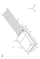
- FIG. 1 is a perspective view showing an optical fiber connection component 1 according to the first embodiment.
- the optical fiber connection component 1 is a first optical fiber that holds a plurality of optical fibers 2 (12 optical fibers 2 in the first embodiment) arranged in the X-axis direction (first direction) and a plurality of optical fibers 2.
- a fiber holding member 3 and a second optical fiber holding member 6 for holding the glass fibers 20 of a plurality of optical fibers 2 are provided.
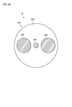
- each optical fiber 2 is arranged in the X-axis direction while being separated from each other. As shown in FIG. 2, each optical fiber 2 has a structure that is not axisymmetric with respect to the central axis in a cross section perpendicular to the central axis (not shown) extending in the longitudinal direction of the optical fiber 2. Therefore, it is necessary to perform rotational alignment for each optical fiber 2.
- each optical fiber 2 is a multi-core fiber having a plurality of cores 24.
- Each optical fiber 2 has a glass fiber 20 and a resin coating portion 21 that covers the glass fiber 20.
- the glass fiber 20 has a plurality of cores 24 through which signal light propagates, a marker 25, and a clad 23 that covers the plurality of cores 24 and the marker 25.
- the refractive index of each core 24 is larger than that of the clad 23.
- the refractive index of the marker 25 is different from that of the clad 23.
- the marker 25 is used in the rotational alignment step of the optical fiber 2 described later.
- the first optical fiber holding member 3 holds a plurality of glass fibers 20 so that the plurality of glass fibers 20 exposed from the resin coating portion 21 are arranged in the X-axis direction.
- the first optical fiber holding member 3 has a first substrate 4 and a first lid portion 5 facing the first substrate 4 via a plurality of glass fibers 20.
- the first substrate 4 has a holding region 43 for holding the resin coating portion 21 and a holding region 44 for holding each glass fiber 20 exposed from the resin coating portion.
- the holding region 44 is provided with a plurality of first groove portions 46 (see FIG. 4) having a V-shaped cross section for holding one of the corresponding glass fibers 20.
- the second optical fiber holding member 6 holds the plurality of glass fibers 20 so that the plurality of glass fibers 20 protruding from the first optical fiber holding member 3 in the Z-axis direction are arranged in the X-axis direction.
- the second optical fiber holding member 6 has a second substrate 7 and a second lid portion 8 facing the second substrate 7 via a plurality of glass fibers 20.
- the second substrate 7 is provided with a plurality of second groove portions 76 (see FIG. 8) having a V-shaped cross section, each holding one of the corresponding glass fibers 20.
- the second optical fiber holding member 6 is fixed to the first optical fiber holding member 3 via an adhesive.
- the second substrate 7 is fixed to the first substrate 4 via an adhesive
- the second lid portion 8 is fixed to the first lid portion 5 via an adhesive.
- the end face of the second optical fiber holding member 6 is flush with the end face 22 of each glass fiber 20.
- the end surface 72 of the second substrate 7 and the end surface 82 of the second lid portion 8 are flush with the end surface 22 of each glass fiber 20.
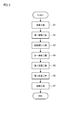
- FIG. 3 is a flowchart for explaining the manufacturing method of the optical fiber connection component 1 according to the present disclosure.
- the preparation step S1 a plurality of optical fibers 2 in which the end portion of the glass fiber 20 is exposed from the resin coating portion 21 are prepared.
- the plurality of optical fibers 2 are not adhered to each other, it is not necessary to separately provide a step of separating each optical fiber 2. Further, the end portion of each glass fiber 20 can be exposed from the resin coating portion 21 by using a predetermined tool.
- a plurality of optical fibers 2 are mounted on the first optical fiber holding member 3.
- each optical fiber 2 is arranged so that the glass fibers 20 exposed from the resin coating portion 21 are arranged in the X-axis direction and project outward from the first substrate 4 in the Z-axis direction. 1 It is mounted on the substrate 4.
- the resin coating portion 21 is held in the holding region 43 of the first substrate 4, and each of the plurality of glass fibers 20 exposed from the resin coating portion 21 is in the holding region 44 of the first substrate 4. It is held in the corresponding one of the grooves 46 (see FIG. 5).
- the orientation (rotational position) around the central axis of each optical fiber 2 is adjusted (that is, the rotational alignment of each optical fiber 2 is performed).
- the surface of each glass fiber 20 protruding from the first optical fiber holding member 3 may be imaged by a camera (not shown).
- the rotation centering device (not shown) may automatically adjust the rotation position of each glass fiber 20 based on the captured image showing the surface of the glass fiber 20 acquired by the camera.
- the rotational position of the glass fiber 20 may be adjusted so that the rotational position of the marker 25 (see FIG. 2) of the glass fiber 20 coincides with a predetermined rotational position. In this way, the rotational positions of the plurality of cores 24 are adjusted to desired rotational positions through the rotational alignment step of the optical fiber 2.
- the first bonding step S4 a plurality of glass fibers 20 are bonded to the first optical fiber holding member 3 using an ultraviolet curable resin (an example of the first adhesive).
- an ultraviolet curable resin an example of the first adhesive.
- the first lid portion 5 is arranged on the holding region 44 of the first substrate 4 via each glass fiber 20. (See FIG. 6).
- the ultraviolet curable resin is attached to the first groove portion 46, the first substrate 4, and the first lid portion 5. It is introduced into the gap between them (see FIGS. 7A and 7B).
- the ultraviolet curable resin may be poured into the gap between the first lid portion 5 and the first substrate 4 from the holding region 43 side. After that, the ultraviolet curable resin is cured by irradiating the ultraviolet curable resin with ultraviolet rays. In this way, each glass fiber 20 is adhered to the first substrate 4 and the first lid portion 5 by the ultraviolet curable resin.
- each optical fiber 2 is mounted on the second substrate 7 so that the glass fibers 20 protruding from the first optical fiber holding member 3 are arranged in the X-axis direction.
- each of the plurality of glass fibers 20 is held by the corresponding one of the plurality of second groove portions 76 in the second substrate 7.
- the tip of each glass fiber 20 slightly protrudes from the end surface 72 of the second substrate 7 in the Z-axis direction.
- the second substrate 7 is adhered to the first substrate 4 via an adhesive.
- a plurality of glass fibers 20 are bonded to the second optical fiber holding member 6 using an ultraviolet curable resin (an example of the second adhesive).
- an ultraviolet curable resin an example of the second adhesive.
- the second lid portion 8 is arranged on the second substrate 7 via each glass fiber 20.
- the ultraviolet curable resin is attached to the second groove portion 76, the second substrate 7, and the second lid portion 8. Introduced in the gap between.
- the ultraviolet curable resin may be poured into the gap between the second lid portion 8 and the second substrate 7 from the end surface 22 side of each glass fiber 20.
- the ultraviolet curable resin is cured by irradiating the ultraviolet curable resin with ultraviolet rays.
- each glass fiber 20 is adhered to the second substrate 7 and the second lid portion 8 by the ultraviolet curable resin.
- the second lid portion 8 is adhered to the first lid portion 5 via an adhesive.
- the end faces 22 of the plurality of glass fibers 20 and the end faces of the second optical fiber holding member 6 are polished. Specifically, the end face 22 of each glass fiber 20 and the end face 22 of each glass fiber 20 are flush with each other so that the end face 22 of each glass fiber 20, the end face 72 of the second substrate 7, and the end face 82 of the second lid portion 8 are flush with each other.
- the end surface 72 of the 2 substrate 7 and the end surface 82 of the second lid portion 8 are polished.
- the amount of protrusion of the glass fiber 20 protruding from the end surface 72 of the second substrate 7 and the end surface 82 of the second lid portion 8 in the Z-axis direction is D2 (mm)
- the glass fiber is D2 or more. In this way, the optical fiber connection component 1 as shown in FIG. 1 is manufactured through the polishing step S7.
- the rotational position of the core 24 above does not change significantly from the rotational position of the core 24 on the end face 22 of the glass fiber 20 observed by the rotational alignment of the optical fiber 2.
- the rotation position of the core 24 on the end face 22 of the glass fiber 20 of the optical fiber connection component 1 manufactured through the polishing process of the glass fiber 20 deviates from the desired position adjusted in the rotation alignment process. Can be prevented. Therefore, it is possible to prevent a situation in which the coupling loss between the optical fiber connecting component 1 and the external optical component (optical waveguide circuit or another optical fiber) increases. In this way, it is possible to improve the optical characteristics of the optical fiber connecting component 1 through the manufacturing method of the optical fiber connecting component 1 according to the first embodiment. Further, according to the first embodiment, since the first optical fiber holding member 3 and the second optical fiber holding member 6 are fixed to each other via an adhesive, the strength of the optical fiber connecting component 1 can be ensured. ..
- each glass fiber 20 and the first optical fiber holding member 3 are bonded to each other by using an ultraviolet curable resin as an example of the adhesive, and each glass fiber 20 and the second optical fiber holding member 6 are attached.
- the first embodiment should not be limited to this.
- a thermosetting resin may be used instead of the ultraviolet curable resin.
- the optical fiber connection component 1 includes 12 optical fibers 2, but the number of optical fibers 2 mounted on the optical fiber connection component 1 is not particularly limited. For example, the number of optical fibers 2 mounted on the optical fiber connection component 1 may be one.
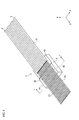
- FIG. 11 is a diagram for explaining a method of manufacturing the optical fiber connection component 1A according to the second embodiment.
- FIG. 12 is a perspective view showing the optical fiber connection component 1A.
- the optical fiber connection component 1A according to the second embodiment is different from the optical fiber connection component 1 according to the first embodiment in that the outer sizes of the first lid portion 5A and the second lid portion 8A are different. It's different.
- the differences between the optical fiber connection component 1 according to the first embodiment and the optical fiber connection component 1A according to the second embodiment will be mainly described.
- the components having the same reference numbers as the components described in the first embodiment will not be repeatedly described.
- the optical fiber connecting component 1A includes a plurality of optical fibers 2, a first optical fiber holding member 3A, and a second optical fiber holding member 6A.
- the first optical fiber holding member 3A has a first substrate 4 and a first lid portion 5A facing the first substrate 4 via each glass fiber 20.
- the outer size of the first lid portion 5A in the Z-axis direction is smaller than the outer size of the first lid portion 5 of the first embodiment in the Z-axis direction.
- the second optical fiber holding member 6A has a second substrate 7 and a second lid portion 8A facing the first substrate 4 and the second substrate 7 via each glass fiber 20.
- the outer size of the second lid 8A in the Z-axis direction is larger than the outer size of the second lid 8 in the first embodiment in the Z-axis direction.
- a part of the second lid portion 8A is adhered to each glass fiber 20 and the first substrate 4 by an ultraviolet curable resin, and another part of the second lid portion 8A is adhered to each glass fiber 20 by an ultraviolet curable resin. And is adhered to the second substrate 7.
- the strength of the optical fiber connection component 1A is increased. be able to.
- each glass fiber 20 is bonded to the first optical fiber holding member 3A using an ultraviolet curable resin (first bonding step S4).
- first bonding step S4 the first lid portion 5A is arranged on the holding region 44 of the first substrate 4 via each glass fiber 20 (see FIG. 11).
- the ultraviolet curable resin is attached to the first groove portion 46, the first substrate 4, and the first lid portion 5A. Introduced in the gap between. After that, the ultraviolet curable resin is cured by irradiating the ultraviolet curable resin with ultraviolet rays. In this way, each glass fiber 20 is adhered to the first substrate 4 and the first lid portion 5A by the ultraviolet curable resin.
- a plurality of glass fibers 20 projecting outward from the first optical fiber holding member 3A in the Z-axis direction are mounted on the second optical fiber holding member 6A.
- the plurality of glass fibers 20 are bonded to the second optical fiber holding member 6A using the ultraviolet curable resin.
- a part of the second lid portion 8A is mounted on the first substrate 4 via each glass fiber 20, and the remaining part of the second lid portion 8A attaches each glass fiber 20. It is mounted on the second substrate 7 via.
- the ultraviolet curable resin is attached to the gap between the second substrate 7 and the second lid portion 8A and the first substrate 4. It is introduced into the gap between the second lid portion 8A and the second lid portion 8A.
- the ultraviolet curable resin is poured from the end surface 22 side of each glass fiber 20 into the gap between the second lid portion 8A and the second substrate 7 and the gap between the second lid portion 8A and the first substrate 4. May be good. After that, the ultraviolet curable resin is cured by irradiating the ultraviolet curable resin with ultraviolet rays. In this way, each glass fiber 20 is adhered to the second substrate 7, the second lid portion 8A, and the first substrate 4 by the ultraviolet curable resin.
- the polishing step S7 the end face 22 of each glass fiber 20 and the end face of the second optical fiber holding member 6A are polished. At this point, the end face 22 of each glass fiber 20 and the second The end face 72 of the substrate 7 and the end face 82A of the second lid portion 8A are polished.
- the first optical fiber holding member 3A and the second optical fiber holding member 6A can be indirectly fixed to each other without providing a step of directly bonding the 3A and the second optical fiber holding member 6A.
- FIG. 13A is a diagram showing a first optical fiber holding member 3B according to a modified example.
- FIG. 13B is a diagram showing a second optical fiber holding member 6B according to a modified example.
- the first optical fiber holding member 3B may be used for the optical fiber connecting component 1 instead of the first optical fiber holding member 3 according to the first embodiment.
- the first optical fiber holding member 3B is a first hole capillary having a plurality of first hole portions 3b arranged in the X-axis direction. Each of the plurality of glass fibers 20 is inserted into the corresponding one of the plurality of first hole portions 3b. As described above, each of the plurality of first hole portions 3b holds the corresponding one of the plurality of glass fibers 20.
- the second optical fiber holding member 6B may be used for the optical fiber connecting component 1.
- the second optical fiber holding member 6B is a second hole capillary having a plurality of second hole portions 6b arranged in the X-axis direction.
- Each of the plurality of glass fibers 20 projecting from the first optical fiber holding member 3B in the Z-axis direction is inserted into the corresponding one of the plurality of second hole portions 6b.
- each of the plurality of second hole portions 6b holds the corresponding one of the plurality of glass fibers 20 protruding from the first optical fiber holding member 3B.
- each optical fiber 2 is mounted on the first optical fiber holding member 3B by inserting each glass fiber 20 into the corresponding one of the plurality of first hole portions 3b.
- each glass fiber 20 is bonded to the first optical fiber holding member 3B by the ultraviolet curable resin (first bonding step S4).
- each glass fiber 20 protruding from the first optical fiber holding member 3B is inserted into the corresponding one of the plurality of second hole portions 6b, so that each glass fiber 20 is second. It is mounted on the optical fiber holding member 6B.
- the second bonding step S6 after each glass fiber 20 is bonded to the second optical fiber holding member 6B by the ultraviolet curable resin, the end face of the second optical fiber holding member 6B and the end face 22 of each glass fiber 20 are attached. Be polished.
- the amount of polishing of each glass fiber 20 can be reduced, so that the rotation position of the core of the optical fiber connection component 1 manufactured through the polishing process of the glass fiber 20 is adjusted by the rotation alignment process. It is possible to prevent a situation in which the desired rotation position is deviated. As described above, it is possible to provide a method for manufacturing the optical fiber connection component 1 capable of improving the optical characteristics of the optical fiber connection component 1.
- the optical fiber is a multi-core fiber having a plurality of cores, but the optical fiber is not limited to the multi-core fiber.
- the structure of the optical fiber is not particularly limited as long as the glass fiber of the optical fiber has a structure that is not axisymmetric with respect to its central axis.
- the polarization-retaining fiber 2A may be applied to the optical fiber connection component 1 instead of the optical fiber 2.
- the polarization-retaining fiber 2A has a glass fiber 20A and a resin coating portion (not shown) covering the glass fiber 20A.
- the glass fiber 20A is arranged between the pair of stress applying portions 26A and the pair of stress applying portions 26A, and has a core 24A through which signal light propagates, a pair of stress applying portions 26A, and a clad 23A covering the core 24A. You may have.
- the polarization-retaining fiber 2A is applied to the optical fiber connection component instead of the optical fiber 2, it is possible to provide an optical fiber connection component capable of connecting the polarization-retaining fiber with low crosstalk.
- the plurality of optical fibers are a plurality of single-core optical fibers that are not bonded to each other, but the present invention is not limited to this.
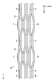
- a plurality of optical fibers 2B included in the intermittent adhesive fiber ribbon 120 may be applied to the optical fiber connecting component 1 instead of the optical fiber 2.
- a non-bonded region 122 which is a region where adjacent optical fibers 2B are not bonded, is intermittently provided along the Z-axis direction.
- the intermittent adhesive fiber ribbon is an intermittent adhesive type in which completely separated regions in which each optical fiber is completely separated from each other and adhesive regions in which each optical fiber is adhered to each other are alternately provided in the Z-axis direction (longitudinal direction). It may be a fiber ribbon. In this case, it is not necessary to separately provide a step of separating each optical fiber before the step of mounting each optical fiber on the first optical fiber holding member.
- the first optical fiber holding member and the second optical fiber holding member need only be able to hold the optical fiber, and their structures are not particularly limited.
- the first optical fiber holding member and the second optical fiber holding member may be a cylindrical ferrule or an MT ferrule.
- 1,1A Optical fiber connection component 2,2A, 2B: Optical fiber 3,3A, 3B: First optical fiber holding member 3b: First hole 4: First substrate 5,5A: First lid 6,6A , 6B: Second optical fiber holding member 6b: Second hole 7: Second substrate 8, 8A: Second lid 20, 20A: Glass fiber 21: Resin coating 22: End face 23, 23A: Clad 24, 24A : Core 25: Marker 26A: Stress applying portion 43, 44: Holding region 46: First groove portion 76: Second groove portion 120: Intermittent adhesive fiber ribbon 122: Non-adhesive region
Abstract
A method for manufacturing an optical fiber connection component according to the present invention comprises: a step for preparing an optical fiber (2) having a glass fiber (20) and a resin coated part (21) covering the glass fiber; a step for mounting the optical fiber on a first optical fiber holding member (3) to protrude outward from the first optical fiber holding member; a rotational alignment step for adjusting the orientation around the central axis of the optical fiber; a step for bonding the glass fiber (20) to the first optical fiber holding member (3) using a first adhesive; a step for mounting the glass fiber (20) on a second optical fiber holding member (6) so that the glass fiber (20) protruding outward from the first optical fiber holding member (3) is arranged in a first direction; a step for bonding the glass fiber (20) to the second optical fiber holding member (6) using a second adhesive; and a step for polishing an end surface (22) of the glass fiber and an end surface (72) of the second optical fiber holding member so that the end surface (22) of the glass fiber is flush with the end surface (72) of the second optical fiber holding member.
Description
本開示は、光ファイバ接続部品及び光ファイバ接続部品の製造方法に関する。
本出願は、2020年3月16日出願の日本出願第2020―045286号に基づく優先権を主張し、前記日本出願に記載された全ての記載内容を援用するものである。 The present disclosure relates to an optical fiber connection component and a method for manufacturing the optical fiber connection component.
This application claims priority based on Japanese Application No. 2020-545286 filed on March 16, 2020, and incorporates all the contents described in the Japanese application.
特許文献1には、マルチコアファイバを備えた光コネクタの製造方法が開示されている。特許文献1に開示された製造方法によれば、マルチコアファイバがコネクタフェルールに設けられたV溝に配置された後に、マルチコアファイバの中心軸周りの方位が調整(即ち、マルチコアファイバが回転調心)される。
Patent Document 1 discloses a method for manufacturing an optical connector including a multi-core fiber. According to the manufacturing method disclosed in Patent Document 1, after the multi-core fiber is arranged in the V-groove provided in the connector ferrule, the orientation around the central axis of the multi-core fiber is adjusted (that is, the multi-core fiber is rotationally aligned). Will be done.
本開示の一態様の光ファイバ接続部品の製造方法は、コアとコアを覆うクラッドとを有するガラスファイバであって、ガラスファイバの中心軸に垂直な断面において中心軸に対して軸対称でない構造を有するガラスファイバと、ガラスファイバを覆う樹脂被覆部とを有し、ガラスファイバの端部が樹脂被覆部から露出した一または複数の光ファイバを用意する工程と、樹脂被覆部から露出した一または複数のガラスファイバが第1方向に配列されると共に、第1光ファイバ保持部材から外部に突出するように、一または複数の光ファイバを第1光ファイバ保持部材に搭載する第一搭載工程と、一または複数の光ファイバの中心軸周りの方位を調整する回転調心工程と、第1接着剤を用いて一または複数のガラスファイバを第1光ファイバ保持部材に接着する第一接着工程と、第1光ファイバ保持部材から外部に突出した一または複数のガラスファイバが前記第1方向に配列されるように、一または複数のガラスファイバを第2光ファイバ保持部材に搭載する第二搭載工程と、第2接着剤を用いて一または複数のガラスファイバを第2光ファイバ保持部材に接着する第二接着工程と、一または複数のガラスファイバの端面が第2光ファイバ保持部材の端面と面一となるように、一または複数のガラスファイバの端面と前記第2光ファイバ保持部材の端面とを研磨する工程と、を含む。
The method for manufacturing an optical fiber connecting component according to one aspect of the present disclosure is a glass fiber having a core and a clad covering the core, and has a structure that is not axially symmetric with respect to the central axis in a cross section perpendicular to the central axis of the glass fiber. A step of preparing one or more optical fibers having a glass fiber having a glass fiber and a resin coating portion covering the glass fiber, and the end portion of the glass fiber exposed from the resin coating portion, and one or more exposed from the resin coating portion. 1 Alternatively, a rotational alignment step of adjusting the orientation around the central axis of the plurality of optical fibers, a first bonding step of adhering one or more glass fibers to the first optical fiber holding member using the first adhesive, and a first step. A second mounting step of mounting one or more glass fibers on the second optical fiber holding member so that the one or more glass fibers protruding outward from the one optical fiber holding member are arranged in the first direction. The second bonding step of adhering one or more glass fibers to the second optical fiber holding member using the second adhesive, and the end face of the one or more glass fibers flush with the end face of the second optical fiber holding member. The step of polishing the end face of one or more glass fibers and the end face of the second optical fiber holding member is included.
本開示の一態様の光ファイバ接続部品は、コアとコアを覆うクラッドとを有するガラスファイバであって、ガラスファイバの中心軸に垂直な断面において中心軸に対して軸対称でない構造を有するガラスファイバと、ガラスファイバを覆う樹脂被覆部とを有し、ガラスファイバの端部が樹脂被覆部から露出した一または複数の光ファイバと、第1光ファイバ保持部材であって、樹脂被覆部から露出した一または複数のガラスファイバが第1方向に配列されると共に、第1光ファイバ保持部材から外部に突出するように、一または複数のガラスファイバを保持する第1光ファイバ保持部材と、第1光ファイバ保持部材から突出した一または複数のガラスファイバが第1方向に配列されるように一または複数のガラスファイバを保持する第2光ファイバ保持部材と、を備える。第2光ファイバ保持部材の端面は、一または複数のガラスファイバの端面と面一である。
The optical fiber connection component of one aspect of the present disclosure is a glass fiber having a core and a clad covering the core, and has a structure that is not axially symmetric with respect to the central axis in a cross section perpendicular to the central axis of the glass fiber. And one or more optical fibers having a resin coating portion covering the glass fiber and the end portion of the glass fiber exposed from the resin coating portion, and a first optical fiber holding member, which is exposed from the resin coating portion. A first optical fiber holding member for holding one or more glass fibers and a first optical fiber so that one or more glass fibers are arranged in the first direction and project outward from the first optical fiber holding member. It includes a second optical fiber holding member that holds the one or more glass fibers so that the one or more glass fibers protruding from the fiber holding member are arranged in the first direction. The end face of the second optical fiber holding member is flush with the end face of one or more glass fibers.
[本開示が解決しようとする課題]
マルチコアファイバを備えた光コネクタの製造方法では、マルチコアファイバが回転調心された後に、マルチコアファイバとコネクタフェルールが接着剤により固定される。その後、マルチコアファイバの端面とコネクタフェルールの端面が面一となるようにコネクタフェルールから突出したマルチコアファイバの端面が研磨される。 [Issues to be solved by this disclosure]
In the method for manufacturing an optical connector including a multi-core fiber, the multi-core fiber and the connector ferrule are fixed by an adhesive after the multi-core fiber is rotationally aligned. Then, the end face of the multi-core fiber protruding from the connector ferrule is polished so that the end face of the multi-core fiber and the end face of the connector ferrule are flush with each other.
ところで、マルチコアファイバのコアの位置は、マルチコアファイバの長手方向に沿って変動していることが多い。この場合、マルチコアファイバの研磨工程後におけるマルチコアファイバの端面上のコアの位置は、マルチコアファイバの端面の研磨量に応じて回転調心工程で観察したマルチコアファイバの端面上のコアの位置から変動する場合がある。このため、製造された光コネクタにおけるマルチコアファイバの端面上のコアの位置が回転調心工程で調整した所望の位置からずれてしまい、光コネクタと光導波路回路等の外部光学部品との間の結合損失が増大してしまう虞がある。このように、マルチコアファイバを備えた光コネクタの光学特性を改善する余地がある。
By the way, the position of the core of the multi-core fiber often fluctuates along the longitudinal direction of the multi-core fiber. In this case, the position of the core on the end face of the multi-core fiber after the polishing step of the multi-core fiber varies from the position of the core on the end face of the multi-core fiber observed in the rotational alignment step according to the amount of polishing of the end face of the multi-core fiber. In some cases. As a result, the position of the core on the end face of the multi-core fiber in the manufactured optical connector deviates from the desired position adjusted in the rotational alignment process, and the coupling between the optical connector and an external optical component such as an optical waveguide circuit There is a risk that the loss will increase. As described above, there is room for improving the optical characteristics of the optical connector including the multi-core fiber.
最初に本開示の実施形態の内容を列記して説明する。
(1)コアとコアを覆うクラッドとを有するガラスファイバであって、ガラスファイバの中心軸に垂直な断面において中心軸に対して軸対称でない構造を有するガラスファイバと、ガラスファイバを覆う樹脂被覆部とを有し、ガラスファイバの端部が樹脂被覆部から露出した一または複数の光ファイバを用意する工程と、樹脂被覆部から露出した一または複数のガラスファイバが第1方向に配列されると共に、第1光ファイバ保持部材から外部に突出するように、一または複数の光ファイバを第1光ファイバ保持部材に搭載する第一搭載工程と、一または複数の光ファイバの中心軸周りの方位を調整する回転調心工程と、第1接着剤を用いて一または複数のガラスファイバを第1光ファイバ保持部材に接着する第一接着工程と、第1光ファイバ保持部材から外部に突出した一または複数のガラスファイバが第1方向に配列されるように、一または複数のガラスファイバを第2光ファイバ保持部材に搭載する第二搭載工程と、第2接着剤を用いて一または複数のガラスファイバを第2光ファイバ保持部材に接着する第二接着工程と、一または複数のガラスファイバの端面が第2光ファイバ保持部材の端面と面一となるように、一または複数のガラスファイバの端面と第2光ファイバ保持部材の端面とを研磨する工程と、を含む、光ファイバ接続部品の製造方法。 First, the contents of the embodiments of the present disclosure will be listed and described.
(1) A glass fiber having a core and a clad covering the core, having a structure not axially symmetric with respect to the central axis in a cross section perpendicular to the central axis of the glass fiber, and a resin coating portion covering the glass fiber. A step of preparing one or more optical fibers whose end portions of the glass fibers are exposed from the resin coating portion, and one or more glass fibers exposed from the resin coating portion are arranged in the first direction. The first mounting process of mounting one or more optical fibers on the first optical fiber holding member and the orientation around the central axis of the one or more optical fibers so as to project outward from the first optical fiber holding member. A rotational alignment step to adjust, a first bonding step of adhering one or more glass fibers to the first optical fiber holding member using a first adhesive, and one or more protruding outward from the first optical fiber holding member. A second mounting process in which one or more glass fibers are mounted on the second optical fiber holding member so that the plurality of glass fibers are arranged in the first direction, and one or more glass fibers using a second adhesive. And the end face of one or more glass fibers so that the end face of one or more glass fibers is flush with the end face of the second glass fiber holding member. A method for manufacturing an optical fiber connecting component, which comprises a step of polishing an end face of a second optical fiber holding member.
上記製造方法によれば、各ガラスファイバの端面の研磨量を低減することが可能となる。このため、ガラスファイバのコアの位置がガラスファイバの長手方向に沿って変動する場合であっても、ガラスファイバの端面の研磨が終了した時点でのガラスファイバの端面上におけるコアの位置は、光ファイバの回転調心工程直後に観察したガラスファイバの端面上におけるコアの位置からは大きく変動しない。このため、光ファイバ接続部品と外部光学部品(例えば、光導波路回路)との間の結合損失が増大してしまうといった状況を防止可能となる。
According to the above manufacturing method, it is possible to reduce the amount of polishing of the end face of each glass fiber. Therefore, even when the position of the core of the glass fiber fluctuates along the longitudinal direction of the glass fiber, the position of the core on the end face of the glass fiber at the time when the polishing of the end face of the glass fiber is completed is optical. It does not fluctuate significantly from the position of the core on the end face of the glass fiber observed immediately after the fiber rotation centering process. Therefore, it is possible to prevent a situation in which the coupling loss between the optical fiber connecting component and the external optical component (for example, an optical waveguide circuit) increases.
(2)第1光ファイバ保持部材と第2光ファイバ保持部材とを互いに接着する保持部材接着工程をさらに含む、項目(1)に記載の光ファイバ接続部品の製造方法。
(2) The method for manufacturing an optical fiber connecting component according to item (1), further comprising a holding member bonding step of bonding the first optical fiber holding member and the second optical fiber holding member to each other.
上記製造方法によれば、第1光ファイバ保持部材と第2光ファイバ保持部材が互いに固定されているため、光ファイバ接続部品の強度を上げることができる。
According to the above manufacturing method, since the first optical fiber holding member and the second optical fiber holding member are fixed to each other, the strength of the optical fiber connecting component can be increased.
(3)前記第1光ファイバ保持部材は、各々が前記一または複数のガラスファイバの対応する一つを保持する一または複数の第1溝部を有する第1基板と、前記一または複数のガラスファイバを介して前記第1基板と対向する第1蓋部と、を備え、第2光ファイバ保持部材は、各々が一または複数のガラスファイバの対応する一つを保持する一または複数の第2溝部を有する第2基板と、一または複数のガラスファイバを介して前記第2基板と対向する第2蓋部と、を備え、第一搭載工程は、樹脂被覆部から露出した一または複数のガラスファイバの各々が一または複数の第1溝部のうちの対応する一つに保持されると共に、第1基板から外部に突出するように、一または複数の光ファイバを第1基板に搭載することを含み、第一接着工程は、一または複数のガラスファイバが第1基板及び第1蓋部に接着されるように、第1接着剤を一または複数の第1溝部内に設けることを含み、第二搭載工程は、第1基板から外部に突出した一または複数のガラスファイバの各々が一または複数の第2溝部のうちの対応する一つに保持されるように、一または複数のガラスファイバを前記第2基板に搭載することを含み、第二接着工程は、一または複数のガラスファイバが第2基板及び前記第2蓋部に接着されるように、第2接着剤を一または複数の第2溝部内に設けることを含み、研磨する工程は、一または複数のガラスファイバの端面が第2基板の端面及び第2蓋部の端面と面一となるように、一または複数のガラスファイバの端面と、第2基板の端面と、第2蓋部の端面とを研磨することを含む、項目(1)または項目(2)に記載の光ファイバ接続部品の製造方法。
(3) The first optical fiber holding member includes a first substrate having one or a plurality of first grooves, each of which holds a corresponding one of the one or a plurality of glass fibers, and the one or a plurality of glass fibers. The second optical fiber holding member includes one or more second groove portions each including a first lid portion facing the first substrate via the glass fiber, and each holding a corresponding one or a plurality of glass fibers. The first mounting step includes a second substrate having a second substrate and a second lid portion facing the second substrate via one or more glass fibers, and the first mounting step is one or more glass fibers exposed from the resin coating portion. Each of the above includes being held in the corresponding one of the one or more first grooves and mounting the one or more optical fibers on the first substrate so as to project outward from the first substrate. The first bonding step comprises providing the first adhesive in the one or more first grooves so that the one or more glass fibers are bonded to the first substrate and the first lid. The mounting process said that the one or more glass fibers were held in the corresponding one of the one or more second grooves so that each of the one or more glass fibers projecting outward from the first substrate was held in the corresponding one or more second grooves. The second bonding step comprises mounting the second substrate on the second substrate, and the second bonding step applies the second adhesive to the second substrate and the second lid so that the glass fibers are bonded to the second substrate and the second lid. The step of polishing, including providing in the groove, is the end face of the glass fiber so that the end face of the glass fiber is flush with the end face of the second substrate and the end face of the second lid. The method for manufacturing an optical fiber connecting component according to item (1) or item (2), which comprises polishing the end surface of the second substrate and the end surface of the second lid portion.
上記製造方法によれば、光ファイバを第1光ファイバ保持部材上へ容易に搭載でき、かつ第1光ファイバ保持部材上で高精度に配列させることができる。
According to the above manufacturing method, the optical fibers can be easily mounted on the first optical fiber holding member and can be arranged with high accuracy on the first optical fiber holding member.
(4)第2蓋部は、第1基板及び前記第2基板に対向しており、第二接着工程では、第2基板が第2蓋部を介して第1基板に固定されるように、第2接着剤が第1基板と第2蓋部との間に設けられる、項目(3)に記載の光ファイバ接続部品の製造方法。
(4) The second lid portion faces the first substrate and the second substrate, and in the second bonding step, the second substrate is fixed to the first substrate via the second lid portion. The method for manufacturing an optical fiber connection component according to item (3), wherein the second adhesive is provided between the first substrate and the second lid portion.
上記製造方法によれば、第1基板と第2基板とを接着剤によって直接的に接着する工程を設けずに、第1基板と第2基板とを互いに間接的に固定することができる。
According to the above manufacturing method, the first substrate and the second substrate can be indirectly fixed to each other without providing a step of directly adhering the first substrate and the second substrate with an adhesive.
(5)第1光ファイバ保持部材は、各々が一または複数のガラスファイバを保持する一または複数の第1孔部を有する第1ホールキャピラリを備え、第2光ファイバ保持部材は、各々が一または複数のガラスファイバの対応する一つを保持する一または複数の第2孔部を有する第2ホールキャピラリを備える、項目(1)または項目(2)に記載の光ファイバ接続部品の製造方法。
(5) The first optical fiber holding member includes a first hole capillary having one or more first holes each holding one or more glass fibers, and the second optical fiber holding member is one each. The method for manufacturing an optical fiber connection component according to item (1) or item (2), further comprising a second hole capillary having one or more second holes holding one or more corresponding ones of the plurality of glass fibers.
上記製造方法によれば、部品点数を少なくでき、組み立ての工数を減らすことができる。
According to the above manufacturing method, the number of parts can be reduced and the man-hours for assembly can be reduced.
(6)一または複数の光ファイバは、間欠接着型ファイバリボンに含まれる複数の光ファイバである、項目(1)から項目(5)のうちいずれか一項に記載の光ファイバ接続部品の製造方法。
(6) Manufacture of the optical fiber connection component according to any one of items (1) to (5), wherein the one or more optical fibers are a plurality of optical fibers included in the intermittent adhesive fiber ribbon. Method.
上記によれば、間欠接着型ファイバリボンのうち光ファイバが一体化していない箇所を第1光ファイバ保持部材に搭載することで、各光ファイバを分離させる工程を省くことができる。
According to the above, the step of separating each optical fiber can be omitted by mounting the portion of the intermittent adhesive fiber ribbon in which the optical fiber is not integrated on the first optical fiber holding member.
(7)一または複数の光ファイバは、互いに接着されていない複数の単芯光ファイバである、項目(1)から項目(5)のうちいずれか一項に記載の光ファイバ接続部品の製造方法。
(7) The method for manufacturing an optical fiber connection component according to any one of items (1) to (5), wherein the one or more optical fibers are a plurality of single-core optical fibers that are not bonded to each other. ..
上記によれば、各光ファイバを分離させる工程を省くことができる。
According to the above, the step of separating each optical fiber can be omitted.
(8)一または複数の光ファイバの各々は、複数のコアを有するマルチコアファイバである、項目(1)から項目(7)のうちいずれか一項に記載の光ファイバ接続部品の製造方法。
(8) The method for manufacturing an optical fiber connection component according to any one of items (1) to (7), wherein each of the one or a plurality of optical fibers is a multi-core fiber having a plurality of cores.
上記製造方法によれば、一または複数のマルチコアファイバを低損失で接続可能な光ファイバ接続部品を製造することができる。
According to the above manufacturing method, it is possible to manufacture an optical fiber connection component capable of connecting one or more multi-core fibers with low loss.
(9)一または複数の光ファイバの各々は、偏波保持ファイバである、項目(1)から項目(7)のうちいずれか一項に記載の光ファイバ接続部品の製造方法。
(9) The method for manufacturing an optical fiber connection component according to any one of items (1) to (7), wherein each of the one or a plurality of optical fibers is a polarization-maintaining fiber.
上記製造方法によれば、一または複数の偏波保持ファイバを低クロストークで接続可能な光ファイバ接続部品を製造することができる。
According to the above manufacturing method, it is possible to manufacture an optical fiber connection component capable of connecting one or more polarization-holding fibers with low crosstalk.
(10)コアとコアを覆うクラッドとを有するガラスファイバであって、ガラスファイバの中心軸に垂直な断面において中心軸に対して軸対称でない構造を有するガラスファイバと、ガラスファイバを覆う樹脂被覆部とを有し、ガラスファイバの端部が樹脂被覆部から露出した一または複数の光ファイバと、樹脂被覆部から露出した一または複数のガラスファイバが第1方向に配列されるように一または複数のガラスファイバを保持する第1光ファイバ保持部材と、第1光ファイバ保持部材から突出した一または複数のガラスファイバが第1方向に配列されるように一または複数のガラスファイバを保持する第2光ファイバ保持部材と、を備え、第2光ファイバ保持部材の端面は、一または複数のガラスファイバの端面と面一である、光ファイバ接続部品。
(10) A glass fiber having a core and a clad covering the core, having a structure not axially symmetric with respect to the central axis in a cross section perpendicular to the central axis of the glass fiber, and a resin coating portion covering the glass fiber. One or more optical fibers whose ends of the glass fibers are exposed from the resin coating and one or more so that the one or more glass fibers exposed from the resin coating are arranged in the first direction. A first optical fiber holding member that holds the glass fibers of the above, and a second that holds the one or more glass fibers so that the one or more glass fibers protruding from the first optical fiber holding member are arranged in the first direction. An optical fiber connecting component comprising an optical fiber holding member, wherein the end face of the second optical fiber holding member is flush with the end faces of one or more glass fibers.
上記構成によれば、第1光ファイバ保持部材から突出した一または複数のガラスファイバが第2光ファイバ保持部材によって保持されるため、第1光ファイバ保持部材から外部に突出した各ガラスファイバの端面の研磨量を低減することが可能となる。このため、製造された光ファイバ接続部品のガラスファイバの端面上におけるコアの位置が回転調心工程で調整した所望の位置からずれてしまうといった状況を防止することができるため、光ファイバ接続部品と外部光学部品(例えば、光導波路回路)との間の結合損失が増大してしまうといった状況を防止可能となる。このように、光ファイバ接続部品の光学特性を向上させることが可能となる。
According to the above configuration, since one or more glass fibers protruding from the first optical fiber holding member are held by the second optical fiber holding member, the end face of each glass fiber protruding outward from the first optical fiber holding member. It is possible to reduce the amount of polishing. Therefore, it is possible to prevent a situation in which the position of the core on the end face of the glass fiber of the manufactured optical fiber connecting component deviates from the desired position adjusted in the rotational alignment process. It is possible to prevent a situation in which the coupling loss with an external optical component (for example, an optical waveguide circuit) is increased. In this way, it is possible to improve the optical characteristics of the optical fiber connection component.
(11)第1光ファイバ保持部材は、接着剤を介して第2光ファイバ保持部材に固定されている、項目(10)に記載の光ファイバ接続部品。
(11) The optical fiber connection component according to item (10), wherein the first optical fiber holding member is fixed to the second optical fiber holding member via an adhesive.
上記構成によれば、第1光ファイバ保持部材が接着剤を介して第2光ファイバ保持部材に固定されているため、光ファイバ接続部品の強度を上げることができる。
According to the above configuration, since the first optical fiber holding member is fixed to the second optical fiber holding member via an adhesive, the strength of the optical fiber connecting component can be increased.
(12)前記第1光ファイバ保持部材は、各々が一または複数のガラスファイバの対応する一つを保持する一または複数の第1溝部を有する第1基板と、一または複数のガラスファイバを介して前記第1基板と対向する第1蓋部と、を備え、第2光ファイバ保持部材は、各々が一または複数のガラスファイバの対応する一つを保持する一または複数の第2溝部を有する第2基板と、一または複数のガラスファイバを介して前記第2基板と対向する第2蓋部と、を備える、項目(10)または項目(11)に記載の光ファイバ接続部品。
(12) The first optical fiber holding member is provided via a first substrate having one or a plurality of first grooves, each of which holds a corresponding one or a plurality of glass fibers, and one or a plurality of glass fibers. The second optical fiber holding member includes one or more second grooves, each of which holds a corresponding one of one or more glass fibers. The optical fiber connection component according to item (10) or item (11), comprising a second substrate and a second lid portion facing the second substrate via one or more glass fibers.
上記構成によれば、第1基板と第1蓋部によって樹脂被覆部から露出したガラスファイバを第1方向に配列させるように保持することができると共に、第2基板と第2蓋部によって第1基板から突出したガラスファイバを第1方向に配列させるように保持することができる。
According to the above configuration, the glass fibers exposed from the resin coating can be held by the first substrate and the first lid so as to be arranged in the first direction, and the first substrate and the second lid can hold the glass fibers so as to be arranged in the first direction. The glass fibers protruding from the substrate can be held so as to be arranged in the first direction.
(13)一または複数の光ファイバは複数の光ファイバであり、一または複数の第1溝部は、互いに平行に配列されると共に、各々が前記複数の光ファイバ各々の端部で露出した複数のガラスファイバの対応する一つを保持する複数の第1溝部であり、一または複数の第2溝部は、互いに平行に配列されると共に、各々が前記複数のガラスファイバの対応する一つを保持する複数の第2溝部である、項目(12)に記載の光ファイバ接続部品。
(13) One or a plurality of optical fibers are a plurality of optical fibers, and a plurality of first grooves are arranged in parallel with each other and each is exposed at an end portion of each of the plurality of optical fibers. A plurality of first grooves holding the corresponding one of the glass fibers, the one or more second grooves being arranged parallel to each other and each holding the corresponding one of the plurality of glass fibers. The optical fiber connection component according to item (12), which is a plurality of second grooves.
上記構成によれば、複数の第1溝部によって複数の光ファイバを第1方向に配列させることができると共に、複数の第2溝部によって複数の光ファイバを第1方向に配列させることができる。
According to the above configuration, a plurality of optical fibers can be arranged in the first direction by the plurality of first grooves, and a plurality of optical fibers can be arranged in the first direction by the plurality of second grooves.
(14)第2蓋部は、前記第1基板及び前記第2基板に対向しており、第2基板は、前記第2蓋部を介して前記第1基板に固定されている、項目(12)または項目(13)に記載の光ファイバ接続部品。
(14) The item (12), wherein the second lid portion faces the first substrate and the second substrate, and the second substrate is fixed to the first substrate via the second lid portion. ) Or the optical fiber connection component according to item (13).
上記構成によれば、第2基板が第2接着剤及び第2蓋部を介して第1基板に固定されているため、光ファイバ接続部品の強度を上げることができる。
According to the above configuration, since the second substrate is fixed to the first substrate via the second adhesive and the second lid portion, the strength of the optical fiber connection component can be increased.
(15)第1光ファイバ保持部材は、各々が一または複数のガラスファイバの対応する一つを保持する一または複数の第1孔部を有する第1ホールキャピラリを備え、第2光ファイバ保持部材は、各々が一または複数のガラスファイバの対応する一つを保持する一または複数の第2孔部を有する第2ホールキャピラリを備える、項目(10)または項目(11)に記載の光ファイバ接続部品。
(15) The first optical fiber holding member includes a first hole capillary having one or more first holes, each of which holds one or more corresponding ones of glass fibers, and a second optical fiber holding member. The optical fiber connection according to item (10) or item (11), each comprising a second hole capillary having one or more second holes each holding one or more corresponding ones of glass fibers. parts.
上記構成によれば、第1ホールキャピラリによって樹脂被覆部から露出したガラスファイバを第1方向に配列させるように保持することができると共に、第2ホールキャピラリによって第1ホールキャピラリから突出したガラスファイバを第1方向に配列させるように保持することができる。
According to the above configuration, the glass fibers exposed from the resin coating portion can be held by the first hole capillary so as to be arranged in the first direction, and the glass fibers protruding from the first hole capillary can be held by the second hole capillary. It can be held so as to be arranged in the first direction.
(16)一または複数の光ファイバは複数の光ファイバであり、一または複数の第1孔部は、互いに平行に配列されると共に、各々が複数の光ファイバ各々の端部で露出した複数のガラスファイバの対応する一つを保持する複数の第1孔部であり、一または複数の第2孔部は、互いに平行に配列されると共に、各々が複数のガラスファイバの対応する一つを保持する複数の第2孔部である、項目(15)に記載の光ファイバ接続部品。
(16) One or a plurality of optical fibers are a plurality of optical fibers, and a plurality of first holes are arranged in parallel with each other and each is exposed at an end portion of each of the plurality of optical fibers. A plurality of first holes holding the corresponding one of the glass fibers, one or more of the second holes being arranged parallel to each other and each holding the corresponding one of the plurality of glass fibers. The optical fiber connection component according to item (15), which is a plurality of second holes.
上記構成によれば、複数の第1孔部によって複数の光ファイバを第1方向に配列させることができる共に、複数の第2孔部によって複数の光ファイバを第1方向に配列させることができる。
According to the above configuration, a plurality of optical fibers can be arranged in the first direction by the plurality of first holes, and a plurality of optical fibers can be arranged in the first direction by the plurality of second holes. ..
〔本開示の効果〕
本開示によれば、光ファイバ接続部品の光学特性を向上させることが可能な光ファイバ接続部品の製造方法を提供することができると共に、光学特性が向上した光ファイバ接続部品を提供することができる。 [Effect of the present disclosure]
According to the present disclosure, it is possible to provide a method for manufacturing an optical fiber connection component capable of improving the optical characteristics of the optical fiber connection component, and also to provide an optical fiber connection component having improved optical characteristics. ..
[本開示の実施形態の説明]
以下、実施形態について図面を参照しながら説明する。各図面に示された各部材の寸法は、説明の便宜上、実際の各部材の寸法とは異なる場合がある。実施形態の説明では、理解を容易にするために、光ファイバ保持部材に保持された光ファイバの中心軸に沿ったZ軸、Z軸に対して垂直で複数の光ファイバの並びに沿ったX軸、Z軸とX軸に対して垂直なY軸について言及する。また、本実施形態では、光ファイバ接続部品1は、複数の光ファイバ2を含む光ファイバアレイとして機能する。光ファイバ接続部品1の光ファイバが他の光ファイバと光学的に接続される場合には、光ファイバ接続部品1は、光コネクタとして機能する。 [Explanation of Embodiments of the present disclosure]
Hereinafter, embodiments will be described with reference to the drawings. The dimensions of each member shown in each drawing may differ from the actual dimensions of each member for convenience of explanation. In the description of the embodiment, for ease of understanding, the Z-axis along the central axis of the optical fiber held by the optical fiber holding member, and the X-axis along the array of a plurality of optical fibers perpendicular to the Z-axis. , The Y-axis perpendicular to the Z-axis and the X-axis will be mentioned. Further, in the present embodiment, the optical fiber connection component 1 functions as an optical fiber array including a plurality ofoptical fibers 2. When the optical fiber of the optical fiber connecting component 1 is optically connected to another optical fiber, the optical fiber connecting component 1 functions as an optical connector.
以下、実施形態について図面を参照しながら説明する。各図面に示された各部材の寸法は、説明の便宜上、実際の各部材の寸法とは異なる場合がある。実施形態の説明では、理解を容易にするために、光ファイバ保持部材に保持された光ファイバの中心軸に沿ったZ軸、Z軸に対して垂直で複数の光ファイバの並びに沿ったX軸、Z軸とX軸に対して垂直なY軸について言及する。また、本実施形態では、光ファイバ接続部品1は、複数の光ファイバ2を含む光ファイバアレイとして機能する。光ファイバ接続部品1の光ファイバが他の光ファイバと光学的に接続される場合には、光ファイバ接続部品1は、光コネクタとして機能する。 [Explanation of Embodiments of the present disclosure]
Hereinafter, embodiments will be described with reference to the drawings. The dimensions of each member shown in each drawing may differ from the actual dimensions of each member for convenience of explanation. In the description of the embodiment, for ease of understanding, the Z-axis along the central axis of the optical fiber held by the optical fiber holding member, and the X-axis along the array of a plurality of optical fibers perpendicular to the Z-axis. , The Y-axis perpendicular to the Z-axis and the X-axis will be mentioned. Further, in the present embodiment, the optical fiber connection component 1 functions as an optical fiber array including a plurality of
(第1実施形態)
図1は、第1実施形態に係る光ファイバ接続部品1を示す斜視図である。光ファイバ接続部品1は、X軸方向(第1方向)に配列された複数の光ファイバ2(第1実施形態では12本の光ファイバ2)と、複数の光ファイバ2を保持する第1光ファイバ保持部材3と、複数の光ファイバ2のガラスファイバ20を保持する第2光ファイバ保持部材6とを備える。 (First Embodiment)
FIG. 1 is a perspective view showing an optical fiber connection component 1 according to the first embodiment. The optical fiber connection component 1 is a first optical fiber that holds a plurality of optical fibers 2 (12optical fibers 2 in the first embodiment) arranged in the X-axis direction (first direction) and a plurality of optical fibers 2. A fiber holding member 3 and a second optical fiber holding member 6 for holding the glass fibers 20 of a plurality of optical fibers 2 are provided.
図1は、第1実施形態に係る光ファイバ接続部品1を示す斜視図である。光ファイバ接続部品1は、X軸方向(第1方向)に配列された複数の光ファイバ2(第1実施形態では12本の光ファイバ2)と、複数の光ファイバ2を保持する第1光ファイバ保持部材3と、複数の光ファイバ2のガラスファイバ20を保持する第2光ファイバ保持部材6とを備える。 (First Embodiment)
FIG. 1 is a perspective view showing an optical fiber connection component 1 according to the first embodiment. The optical fiber connection component 1 is a first optical fiber that holds a plurality of optical fibers 2 (12
各光ファイバ2は、互いに分離した状態でX軸方向に配列されている。図2に示すように、各光ファイバ2は、光ファイバ2の長手方向に延びる中心軸(図示せず)に垂直な断面において当該中心軸に対して軸対称ではない構造を有する。このため、各光ファイバ2に対して回転調心を行う必要がある。第1実施形態では、各光ファイバ2は、複数のコア24を有するマルチコアファイバである。各光ファイバ2は、ガラスファイバ20と、ガラスファイバ20を覆う樹脂被覆部21とを有する。
Each optical fiber 2 is arranged in the X-axis direction while being separated from each other. As shown in FIG. 2, each optical fiber 2 has a structure that is not axisymmetric with respect to the central axis in a cross section perpendicular to the central axis (not shown) extending in the longitudinal direction of the optical fiber 2. Therefore, it is necessary to perform rotational alignment for each optical fiber 2. In the first embodiment, each optical fiber 2 is a multi-core fiber having a plurality of cores 24. Each optical fiber 2 has a glass fiber 20 and a resin coating portion 21 that covers the glass fiber 20.
ガラスファイバ20は、信号光が伝搬する複数のコア24と、マーカ25と、複数のコア24とマーカ25とを覆うクラッド23とを有する。各コア24の屈折率はクラッド23の屈折率よりも大きい。マーカ25の屈折率は、クラッド23の屈折率と異なっている。マーカ25は、後述する光ファイバ2の回転調心工程において利用される。
The glass fiber 20 has a plurality of cores 24 through which signal light propagates, a marker 25, and a clad 23 that covers the plurality of cores 24 and the marker 25. The refractive index of each core 24 is larger than that of the clad 23. The refractive index of the marker 25 is different from that of the clad 23. The marker 25 is used in the rotational alignment step of the optical fiber 2 described later.
図1に示すように、各光ファイバ2では、ガラスファイバ20の端部が樹脂被覆部21から露出している。第1光ファイバ保持部材3は、樹脂被覆部21から露出した複数のガラスファイバ20がX軸方向に配列されるように複数のガラスファイバ20を保持する。第1光ファイバ保持部材3は、第1基板4と、複数のガラスファイバ20を介して第1基板4と対向する第1蓋部5とを有する。第1基板4は、樹脂被覆部21を保持する保持領域43と、樹脂被覆部から露出した各ガラスファイバ20を保持する保持領域44とを有する。保持領域44には、各々が対応するガラスファイバ20の一つを保持する断面がV字形状の複数の第1溝部46(図4参照)が設けられている。
As shown in FIG. 1, in each optical fiber 2, the end portion of the glass fiber 20 is exposed from the resin coating portion 21. The first optical fiber holding member 3 holds a plurality of glass fibers 20 so that the plurality of glass fibers 20 exposed from the resin coating portion 21 are arranged in the X-axis direction. The first optical fiber holding member 3 has a first substrate 4 and a first lid portion 5 facing the first substrate 4 via a plurality of glass fibers 20. The first substrate 4 has a holding region 43 for holding the resin coating portion 21 and a holding region 44 for holding each glass fiber 20 exposed from the resin coating portion. The holding region 44 is provided with a plurality of first groove portions 46 (see FIG. 4) having a V-shaped cross section for holding one of the corresponding glass fibers 20.
第2光ファイバ保持部材6は、Z軸方向において第1光ファイバ保持部材3から突出した複数のガラスファイバ20がX軸方向に配列されるように複数のガラスファイバ20を保持する。第2光ファイバ保持部材6は、第2基板7と、複数のガラスファイバ20を介して第2基板7と対向する第2蓋部8とを有する。第2基板7には、各々が対応するガラスファイバ20の一つを保持する断面がV字形状の複数の第2溝部76(図8参照)が設けられている。
The second optical fiber holding member 6 holds the plurality of glass fibers 20 so that the plurality of glass fibers 20 protruding from the first optical fiber holding member 3 in the Z-axis direction are arranged in the X-axis direction. The second optical fiber holding member 6 has a second substrate 7 and a second lid portion 8 facing the second substrate 7 via a plurality of glass fibers 20. The second substrate 7 is provided with a plurality of second groove portions 76 (see FIG. 8) having a V-shaped cross section, each holding one of the corresponding glass fibers 20.
第2光ファイバ保持部材6は、接着剤を介して第1光ファイバ保持部材3に固定されている。特に、第2基板7が接着剤を介して第1基板4に固定されていると共に、第2蓋部8が接着剤を介して第1蓋部5に固定されている。また、第2光ファイバ保持部材6の端面は、各ガラスファイバ20の端面22と面一となっている。特に、第2基板7の端面72と第2蓋部8の端面82が各ガラスファイバ20の端面22と面一となっている。
The second optical fiber holding member 6 is fixed to the first optical fiber holding member 3 via an adhesive. In particular, the second substrate 7 is fixed to the first substrate 4 via an adhesive, and the second lid portion 8 is fixed to the first lid portion 5 via an adhesive. Further, the end face of the second optical fiber holding member 6 is flush with the end face 22 of each glass fiber 20. In particular, the end surface 72 of the second substrate 7 and the end surface 82 of the second lid portion 8 are flush with the end surface 22 of each glass fiber 20.
図3は、本開示に係る光ファイバ接続部品1の製造方法を説明するためのフローチャートである。準備工程S1において、ガラスファイバ20の端部が樹脂被覆部21から露出した複数の光ファイバ2が用意される。第1実施形態では、複数の光ファイバ2は、互いに接着されていないため、各光ファイバ2を分離させる工程を別途設ける必要がない。さらに、所定の工具を用いることで各ガラスファイバ20の端部を樹脂被覆部21から露出させることができる。
FIG. 3 is a flowchart for explaining the manufacturing method of the optical fiber connection component 1 according to the present disclosure. In the preparation step S1, a plurality of optical fibers 2 in which the end portion of the glass fiber 20 is exposed from the resin coating portion 21 are prepared. In the first embodiment, since the plurality of optical fibers 2 are not adhered to each other, it is not necessary to separately provide a step of separating each optical fiber 2. Further, the end portion of each glass fiber 20 can be exposed from the resin coating portion 21 by using a predetermined tool.
次に、第1搭載工程S2において、複数の光ファイバ2が第1光ファイバ保持部材3に搭載される。図4に示すように、樹脂被覆部21から露出した各ガラスファイバ20がX軸方向に配列されると共に、Z軸方向において第1基板4から外部に突出するように、各光ファイバ2が第1基板4に搭載される。また、樹脂被覆部21が第1基板4の保持領域43に保持されると共に、樹脂被覆部21から露出した複数のガラスファイバ20の各々が第1基板4の保持領域44にある複数の第1溝部46のうちの対応する一つに保持される(図5参照)。
Next, in the first mounting step S2, a plurality of optical fibers 2 are mounted on the first optical fiber holding member 3. As shown in FIG. 4, each optical fiber 2 is arranged so that the glass fibers 20 exposed from the resin coating portion 21 are arranged in the X-axis direction and project outward from the first substrate 4 in the Z-axis direction. 1 It is mounted on the substrate 4. Further, the resin coating portion 21 is held in the holding region 43 of the first substrate 4, and each of the plurality of glass fibers 20 exposed from the resin coating portion 21 is in the holding region 44 of the first substrate 4. It is held in the corresponding one of the grooves 46 (see FIG. 5).
次に、回転調心工程S3において、各光ファイバ2の中心軸周りの方位(回転位置)が調整される(つまり、各光ファイバ2の回転調心が行われる)。例えば、第1光ファイバ保持部材3から突出した各ガラスファイバ20の表面が図示しないカメラによって撮像されてもよい。その後、図示しない回転調心装置は、カメラにより取得されたガラスファイバ20の表面を示す撮像画像に基づいて、各ガラスファイバ20の回転位置を自動的に調整してもよい。この点において、ガラスファイバ20のマーカ25(図2参照)の回転位置が所定の回転位置に一致するようにガラスファイバ20の回転位置が調整されてもよい。このように、光ファイバ2の回転調心工程を通じて、複数のコア24の回転位置が所望の回転位置に調整される。
Next, in the rotational alignment step S3, the orientation (rotational position) around the central axis of each optical fiber 2 is adjusted (that is, the rotational alignment of each optical fiber 2 is performed). For example, the surface of each glass fiber 20 protruding from the first optical fiber holding member 3 may be imaged by a camera (not shown). After that, the rotation centering device (not shown) may automatically adjust the rotation position of each glass fiber 20 based on the captured image showing the surface of the glass fiber 20 acquired by the camera. In this respect, the rotational position of the glass fiber 20 may be adjusted so that the rotational position of the marker 25 (see FIG. 2) of the glass fiber 20 coincides with a predetermined rotational position. In this way, the rotational positions of the plurality of cores 24 are adjusted to desired rotational positions through the rotational alignment step of the optical fiber 2.
次に、第一接着工程S4において、紫外線硬化樹脂(第1接着剤の一例)を用いて複数のガラスファイバ20が第1光ファイバ保持部材3に接着される。具体的には、回転調心工程S3において光ファイバ2の回転調心が実行された後に、第1蓋部5が各ガラスファイバ20を介して第1基板4の保持領域44上に配置される(図6参照)。次に、各ガラスファイバ20が第1蓋部5と第1基板4の第1溝部46によって固定された状態で、紫外線硬化樹脂が第1溝部46及び第1基板4と第1蓋部5との間の隙間に導入される(図7A,図7B参照)。紫外線硬化樹脂は、保持領域43側から第1蓋部5と第1基板4との間の隙間に流し込まれてもよい。その後、紫外線硬化樹脂に紫外線を照射することで紫外線硬化樹脂が硬化される。このように、紫外線硬化樹脂により各ガラスファイバ20が第1基板4及び第1蓋部5に接着される。
Next, in the first bonding step S4, a plurality of glass fibers 20 are bonded to the first optical fiber holding member 3 using an ultraviolet curable resin (an example of the first adhesive). Specifically, after the rotational alignment of the optical fiber 2 is executed in the rotational alignment step S3, the first lid portion 5 is arranged on the holding region 44 of the first substrate 4 via each glass fiber 20. (See FIG. 6). Next, in a state where each glass fiber 20 is fixed by the first groove portion 5 and the first groove portion 46 of the first substrate 4, the ultraviolet curable resin is attached to the first groove portion 46, the first substrate 4, and the first lid portion 5. It is introduced into the gap between them (see FIGS. 7A and 7B). The ultraviolet curable resin may be poured into the gap between the first lid portion 5 and the first substrate 4 from the holding region 43 side. After that, the ultraviolet curable resin is cured by irradiating the ultraviolet curable resin with ultraviolet rays. In this way, each glass fiber 20 is adhered to the first substrate 4 and the first lid portion 5 by the ultraviolet curable resin.
次に、第二搭載工程S5において、Z軸方向において第1光ファイバ保持部材3から外部に突出した複数のガラスファイバ20が第2光ファイバ保持部材6に搭載される。図8に示すように、第1光ファイバ保持部材3から突出した各ガラスファイバ20がX軸方向に配列されるように、各光ファイバ2が第2基板7に搭載される。特に、複数のガラスファイバ20の各々が第2基板7にある複数の第2溝部76のうちの対応する一つに保持される。この状態で、各ガラスファイバ20の先端は、Z軸方向において第2基板7の端面72から僅かに突出している。また、本工程において、第2基板7が接着剤を介して第1基板4に接着される。
Next, in the second mounting step S5, a plurality of glass fibers 20 projecting outward from the first optical fiber holding member 3 in the Z-axis direction are mounted on the second optical fiber holding member 6. As shown in FIG. 8, each optical fiber 2 is mounted on the second substrate 7 so that the glass fibers 20 protruding from the first optical fiber holding member 3 are arranged in the X-axis direction. In particular, each of the plurality of glass fibers 20 is held by the corresponding one of the plurality of second groove portions 76 in the second substrate 7. In this state, the tip of each glass fiber 20 slightly protrudes from the end surface 72 of the second substrate 7 in the Z-axis direction. Further, in this step, the second substrate 7 is adhered to the first substrate 4 via an adhesive.
次に、第二接着工程S6において、紫外線硬化樹脂(第2接着剤の一例)を用いて複数のガラスファイバ20が第2光ファイバ保持部材6に接着される。具体的には、図9に示すように、第2蓋部8が各ガラスファイバ20を介して第2基板7上に配置される。次に、各ガラスファイバ20が第2蓋部8と第2基板7の第2溝部76によって固定された状態で、紫外線硬化樹脂が第2溝部76及び第2基板7と第2蓋部8との間の隙間に導入される。紫外線硬化樹脂は、各ガラスファイバ20の端面22の側から第2蓋部8と第2基板7との間の隙間に流し込まれてもよい。その後、紫外線硬化樹脂に紫外線を照射することで紫外線硬化樹脂が硬化される。このように、紫外線硬化樹脂により各ガラスファイバ20が第2基板7及び第2蓋部8に接着される。また、本工程において、第2蓋部8が接着剤を介して第1蓋部5に接着される。
Next, in the second bonding step S6, a plurality of glass fibers 20 are bonded to the second optical fiber holding member 6 using an ultraviolet curable resin (an example of the second adhesive). Specifically, as shown in FIG. 9, the second lid portion 8 is arranged on the second substrate 7 via each glass fiber 20. Next, with each glass fiber 20 fixed by the second groove portion 8 and the second groove portion 76 of the second substrate 7, the ultraviolet curable resin is attached to the second groove portion 76, the second substrate 7, and the second lid portion 8. Introduced in the gap between. The ultraviolet curable resin may be poured into the gap between the second lid portion 8 and the second substrate 7 from the end surface 22 side of each glass fiber 20. After that, the ultraviolet curable resin is cured by irradiating the ultraviolet curable resin with ultraviolet rays. In this way, each glass fiber 20 is adhered to the second substrate 7 and the second lid portion 8 by the ultraviolet curable resin. Further, in this step, the second lid portion 8 is adhered to the first lid portion 5 via an adhesive.
次に、研磨工程S7において、複数のガラスファイバ20の端面22と第2光ファイバ保持部材6の端面とが研磨される。具体的には、各ガラスファイバ20の端面22と、第2基板7の端面72と、第2蓋部8の端面82とが面一となるように、各ガラスファイバ20の端面22と、第2基板7の端面72と、第2蓋部8の端面82が研磨される。例えば、図10に示すように、Z軸方向において、第2基板7の端面72及び第2蓋部8の端面82から突出したガラスファイバ20の突出量がD2(mm)である場合、ガラスファイバ20の研磨量はD2以上となる。このように、研磨工程S7を通じて、図1に示すような光ファイバ接続部品1が製造される。
Next, in the polishing step S7, the end faces 22 of the plurality of glass fibers 20 and the end faces of the second optical fiber holding member 6 are polished. Specifically, the end face 22 of each glass fiber 20 and the end face 22 of each glass fiber 20 are flush with each other so that the end face 22 of each glass fiber 20, the end face 72 of the second substrate 7, and the end face 82 of the second lid portion 8 are flush with each other. The end surface 72 of the 2 substrate 7 and the end surface 82 of the second lid portion 8 are polished. For example, as shown in FIG. 10, when the amount of protrusion of the glass fiber 20 protruding from the end surface 72 of the second substrate 7 and the end surface 82 of the second lid portion 8 in the Z-axis direction is D2 (mm), the glass fiber. The polishing amount of 20 is D2 or more. In this way, the optical fiber connection component 1 as shown in FIG. 1 is manufactured through the polishing step S7.
図6に示すような第1光ファイバ保持部材3から突出した各ガラスファイバ20の突出量D1(mm)と比較して、第2光ファイバ保持部材6から突出した各ガラスファイバ20の突出量D2は短くなるため、第1実施形態によれば研磨工程を通じた各ガラスファイバ20の端面22の研磨量を低減することが可能となる。このように、ガラスファイバ20のコア24の位置がガラスファイバ20の長手方向に沿って変動する場合であっても、ガラスファイバ20の端面22の研磨が終了した時点でのガラスファイバ20の端面22上におけるコア24の回転位置は、光ファイバ2の回転調心で観察したガラスファイバ20の端面22上におけるコア24の回転位置からは大きく変動しない。
The protrusion amount D2 of each glass fiber 20 protruding from the second optical fiber holding member 6 as compared with the protrusion amount D1 (mm) of each glass fiber 20 protruding from the first optical fiber holding member 3 as shown in FIG. Therefore, according to the first embodiment, it is possible to reduce the amount of polishing of the end face 22 of each glass fiber 20 through the polishing step. In this way, even when the position of the core 24 of the glass fiber 20 fluctuates along the longitudinal direction of the glass fiber 20, the end face 22 of the glass fiber 20 at the time when the polishing of the end face 22 of the glass fiber 20 is completed is completed. The rotational position of the core 24 above does not change significantly from the rotational position of the core 24 on the end face 22 of the glass fiber 20 observed by the rotational alignment of the optical fiber 2.
したがって、ガラスファイバ20の研磨工程を通じて製造された光ファイバ接続部品1のガラスファイバ20の端面22上におけるコア24の回転位置が回転調心工程で調整された所望の位置からずれてしまうといった状況を防止することができる。このため、光ファイバ接続部品1と外部光学部品(光導波路回路や別の光ファイバ)との間の結合損失が増大してしまうといった状況を防止可能となる。このように、第1実施形態に係る光ファイバ接続部品1の製造方法を通じて、光ファイバ接続部品1の光学特性を向上させることが可能となる。また、第1実施形態によれば、第1光ファイバ保持部材3と第2光ファイバ保持部材6が接着剤を介して互いに固定されるため、光ファイバ接続部品1の強度を確保することができる。
Therefore, the rotation position of the core 24 on the end face 22 of the glass fiber 20 of the optical fiber connection component 1 manufactured through the polishing process of the glass fiber 20 deviates from the desired position adjusted in the rotation alignment process. Can be prevented. Therefore, it is possible to prevent a situation in which the coupling loss between the optical fiber connecting component 1 and the external optical component (optical waveguide circuit or another optical fiber) increases. In this way, it is possible to improve the optical characteristics of the optical fiber connecting component 1 through the manufacturing method of the optical fiber connecting component 1 according to the first embodiment. Further, according to the first embodiment, since the first optical fiber holding member 3 and the second optical fiber holding member 6 are fixed to each other via an adhesive, the strength of the optical fiber connecting component 1 can be ensured. ..
尚、第1実施形態では、接着剤の一例として紫外線硬化樹脂を用いて各ガラスファイバ20と第1光ファイバ保持部材3が接着されると共に、各ガラスファイバ20と第2光ファイバ保持部材6が接着されているが、第1実施形態はこれに限定されるべきではない。例えば、接着剤の他の一例として紫外線硬化樹脂の代わりに熱硬化性樹脂が使用されてもよい。また、第1実施形態では、光ファイバ接続部品1は、12本の光ファイバ2を備えているが、光ファイバ接続部品1に搭載される光ファイバ2の本数は特に限定されるものではない。例えば、光ファイバ接続部品1に搭載される光ファイバ2の本数は1本であってもよい。
In the first embodiment, each glass fiber 20 and the first optical fiber holding member 3 are bonded to each other by using an ultraviolet curable resin as an example of the adhesive, and each glass fiber 20 and the second optical fiber holding member 6 are attached. Although bonded, the first embodiment should not be limited to this. For example, as another example of the adhesive, a thermosetting resin may be used instead of the ultraviolet curable resin. Further, in the first embodiment, the optical fiber connection component 1 includes 12 optical fibers 2, but the number of optical fibers 2 mounted on the optical fiber connection component 1 is not particularly limited. For example, the number of optical fibers 2 mounted on the optical fiber connection component 1 may be one.
(第2実施形態)
次に、本開示の第2実施形態に係る光ファイバ接続部品1A及びその製造方法について図3、図11及び図12を主に参照して以下に説明する。図11は、第2実施形態に係る光ファイバ接続部品1Aの製造方法を説明するための図である。図12は、光ファイバ接続部品1Aを示す斜視図である。 (Second Embodiment)
Next, the opticalfiber connection component 1A and the manufacturing method thereof according to the second embodiment of the present disclosure will be described below with reference mainly to FIGS. 3, 11 and 12. FIG. 11 is a diagram for explaining a method of manufacturing the optical fiber connection component 1A according to the second embodiment. FIG. 12 is a perspective view showing the optical fiber connection component 1A.
次に、本開示の第2実施形態に係る光ファイバ接続部品1A及びその製造方法について図3、図11及び図12を主に参照して以下に説明する。図11は、第2実施形態に係る光ファイバ接続部品1Aの製造方法を説明するための図である。図12は、光ファイバ接続部品1Aを示す斜視図である。 (Second Embodiment)
Next, the optical
図12に示すように、第2実施形態に係る光ファイバ接続部品1Aは、第1蓋部5Aと第2蓋部8Aの外形サイズが異なる点で第1実施形態に係る光ファイバ接続部品1と相違する。以降の説明では、第1実施形態に係る光ファイバ接続部品1と第2実施形態に係る光ファイバ接続部品1Aとの間の相違点について主に述べる。尚、第2実施形態において、第1実施形態で説明された構成要素と同一の参照番号を有する構成要素について繰り返して説明はしない。
As shown in FIG. 12, the optical fiber connection component 1A according to the second embodiment is different from the optical fiber connection component 1 according to the first embodiment in that the outer sizes of the first lid portion 5A and the second lid portion 8A are different. It's different. In the following description, the differences between the optical fiber connection component 1 according to the first embodiment and the optical fiber connection component 1A according to the second embodiment will be mainly described. In the second embodiment, the components having the same reference numbers as the components described in the first embodiment will not be repeatedly described.
図12に示すように、光ファイバ接続部品1Aは、複数の光ファイバ2と、第1光ファイバ保持部材3Aと、第2光ファイバ保持部材6Aとを備える。第1光ファイバ保持部材3Aは、第1基板4と、各ガラスファイバ20を介して第1基板4に対向する第1蓋部5Aとを有する。第2実施形態では、Z軸方向における第1蓋部5Aの外形サイズは、Z軸方向における第1実施形態の第1蓋部5の外形サイズよりも小さい。第2光ファイバ保持部材6Aは、第2基板7と、各ガラスファイバ20を介して第1基板4及び第2基板7に対向する第2蓋部8Aとを有する。第2実施形態では、Z軸方向における第2蓋部8Aの外形サイズは、Z軸方向における第1実施形態の第2蓋部8の外形サイズよりも大きい。
As shown in FIG. 12, the optical fiber connecting component 1A includes a plurality of optical fibers 2, a first optical fiber holding member 3A, and a second optical fiber holding member 6A. The first optical fiber holding member 3A has a first substrate 4 and a first lid portion 5A facing the first substrate 4 via each glass fiber 20. In the second embodiment, the outer size of the first lid portion 5A in the Z-axis direction is smaller than the outer size of the first lid portion 5 of the first embodiment in the Z-axis direction. The second optical fiber holding member 6A has a second substrate 7 and a second lid portion 8A facing the first substrate 4 and the second substrate 7 via each glass fiber 20. In the second embodiment, the outer size of the second lid 8A in the Z-axis direction is larger than the outer size of the second lid 8 in the first embodiment in the Z-axis direction.
第2蓋部8Aの一部は、紫外線硬化樹脂によって各ガラスファイバ20及び第1基板4に接着されていると共に、第2蓋部8Aの他の一部は、紫外線硬化樹脂によって各ガラスファイバ20及び第2基板7に接着されている。このように、第2実施形態に係る光ファイバ接続部品1Aでは、第2基板7は第2蓋部8Aを介して第1基板4に固定されているため、光ファイバ接続部品1Aの強度を上げることができる。
A part of the second lid portion 8A is adhered to each glass fiber 20 and the first substrate 4 by an ultraviolet curable resin, and another part of the second lid portion 8A is adhered to each glass fiber 20 by an ultraviolet curable resin. And is adhered to the second substrate 7. As described above, in the optical fiber connection component 1A according to the second embodiment, since the second substrate 7 is fixed to the first substrate 4 via the second lid portion 8A, the strength of the optical fiber connection component 1A is increased. be able to.
次に、図3を参照することで光ファイバ接続部品1Aの製造方法について以下に説明する。図3に示すように、準備工程S1~回転調心工程S3が実行された後に、紫外線硬化樹脂を用いて各ガラスファイバ20が第1光ファイバ保持部材3Aに接着される(第一接着工程S4)。より詳細には、第1蓋部5Aが各ガラスファイバ20を介して第1基板4の保持領域44上に配置される(図11参照)。次に、各ガラスファイバ20が第1蓋部5Aと第1基板4の第1溝部46によって固定された状態で、紫外線硬化樹脂が第1溝部46及び第1基板4と第1蓋部5Aとの間の隙間に導入される。その後、紫外線硬化樹脂に紫外線を照射することで紫外線硬化樹脂が硬化される。このように、紫外線硬化樹脂により各ガラスファイバ20が第1基板4及び第1蓋部5Aに接着される。
Next, the manufacturing method of the optical fiber connection component 1A will be described below with reference to FIG. As shown in FIG. 3, after the preparation steps S1 to the rotational alignment step S3 are executed, each glass fiber 20 is bonded to the first optical fiber holding member 3A using an ultraviolet curable resin (first bonding step S4). ). More specifically, the first lid portion 5A is arranged on the holding region 44 of the first substrate 4 via each glass fiber 20 (see FIG. 11). Next, in a state where each glass fiber 20 is fixed by the first lid portion 5A and the first groove portion 46 of the first substrate 4, the ultraviolet curable resin is attached to the first groove portion 46, the first substrate 4, and the first lid portion 5A. Introduced in the gap between. After that, the ultraviolet curable resin is cured by irradiating the ultraviolet curable resin with ultraviolet rays. In this way, each glass fiber 20 is adhered to the first substrate 4 and the first lid portion 5A by the ultraviolet curable resin.
次に、第二搭載工程S5において、Z軸方向において第1光ファイバ保持部材3Aから外部に突出した複数のガラスファイバ20が第2光ファイバ保持部材6Aに搭載される。その後、第二接着工程S6において、紫外線硬化樹脂を用いて複数のガラスファイバ20が第2光ファイバ保持部材6Aに接着される。図12に示すように、第2蓋部8Aの一部が各ガラスファイバ20を介して第1基板4上に搭載されると共に、第2蓋部8Aの残りの一部が各ガラスファイバ20を介して第2基板7上に搭載される。次に、各ガラスファイバ20が第2蓋部8Aと第2基板7によって固定された状態で、紫外線硬化樹脂が第2基板7と第2蓋部8Aとの間の隙間及び第1基板4と第2蓋部8Aとの間の隙間に導入される。
Next, in the second mounting step S5, a plurality of glass fibers 20 projecting outward from the first optical fiber holding member 3A in the Z-axis direction are mounted on the second optical fiber holding member 6A. Then, in the second bonding step S6, the plurality of glass fibers 20 are bonded to the second optical fiber holding member 6A using the ultraviolet curable resin. As shown in FIG. 12, a part of the second lid portion 8A is mounted on the first substrate 4 via each glass fiber 20, and the remaining part of the second lid portion 8A attaches each glass fiber 20. It is mounted on the second substrate 7 via. Next, in a state where each glass fiber 20 is fixed by the second lid portion 8A and the second substrate 7, the ultraviolet curable resin is attached to the gap between the second substrate 7 and the second lid portion 8A and the first substrate 4. It is introduced into the gap between the second lid portion 8A and the second lid portion 8A.
紫外線硬化樹脂は、各ガラスファイバ20の端面22の側から第2蓋部8Aと第2基板7との間の隙間及び第2蓋部8Aと第1基板4との間の隙間に流し込まれてもよい。その後、紫外線硬化樹脂に紫外線を照射することで紫外線硬化樹脂が硬化される。このように、各ガラスファイバ20は、紫外線硬化樹脂により、第2基板7、第2蓋部8A及び第1基板4のそれぞれに接着される。
The ultraviolet curable resin is poured from the end surface 22 side of each glass fiber 20 into the gap between the second lid portion 8A and the second substrate 7 and the gap between the second lid portion 8A and the first substrate 4. May be good. After that, the ultraviolet curable resin is cured by irradiating the ultraviolet curable resin with ultraviolet rays. In this way, each glass fiber 20 is adhered to the second substrate 7, the second lid portion 8A, and the first substrate 4 by the ultraviolet curable resin.
その後、研磨工程S7において、各ガラスファイバ20の端面22と第2光ファイバ保持部材6Aの端面が研磨される。この点において、各ガラスファイバ20の端面22と、第2基板7の端面72と、第2蓋部8Aの端面82Aとが面一となるように、各ガラスファイバ20の端面22と、第2基板7の端面72と、第2蓋部8Aの端面82Aが研磨される。
After that, in the polishing step S7, the end face 22 of each glass fiber 20 and the end face of the second optical fiber holding member 6A are polished. At this point, the end face 22 of each glass fiber 20 and the second The end face 72 of the substrate 7 and the end face 82A of the second lid portion 8A are polished.
このように、第2実施形態に係る光ファイバ接続部品1Aの製造方法では、第2基板7が第2蓋部8Aを介して第1基板4に固定されているため、第1光ファイバ保持部材3Aと第2光ファイバ保持部材6Aとを直接的に接着する工程を設けずに、第1光ファイバ保持部材3Aと第2光ファイバ保持部材6Aとを互いに間接的に固定することができる。
As described above, in the method for manufacturing the optical fiber connecting component 1A according to the second embodiment, since the second substrate 7 is fixed to the first substrate 4 via the second lid portion 8A, the first optical fiber holding member The first optical fiber holding member 3A and the second optical fiber holding member 6A can be indirectly fixed to each other without providing a step of directly bonding the 3A and the second optical fiber holding member 6A.
(第1光ファイバ保持部材及び第2光ファイバ保持部材の変形例)
図13Aは、変形例に係る第1光ファイバ保持部材3Bを示す図である。図13Bは、変形例に係る第2光ファイバ保持部材6Bを示す図である。 (Modification example of the first optical fiber holding member and the second optical fiber holding member)
FIG. 13A is a diagram showing a first opticalfiber holding member 3B according to a modified example. FIG. 13B is a diagram showing a second optical fiber holding member 6B according to a modified example.
図13Aは、変形例に係る第1光ファイバ保持部材3Bを示す図である。図13Bは、変形例に係る第2光ファイバ保持部材6Bを示す図である。 (Modification example of the first optical fiber holding member and the second optical fiber holding member)
FIG. 13A is a diagram showing a first optical
第1実施形態に係る第1光ファイバ保持部材3に代わって、第1光ファイバ保持部材3Bが光ファイバ接続部品1に使用されてもよい。第1光ファイバ保持部材3Bは、X軸方向に配列された複数の第1孔部3bを有する第1ホールキャピラリである。複数のガラスファイバ20の各々は、複数の第1孔部3bのうちの対応する一つに挿入される。このように、複数の第1孔部3bの各々は、複数のガラスファイバ20のうちの対応する一つを保持する。
The first optical fiber holding member 3B may be used for the optical fiber connecting component 1 instead of the first optical fiber holding member 3 according to the first embodiment. The first optical fiber holding member 3B is a first hole capillary having a plurality of first hole portions 3b arranged in the X-axis direction. Each of the plurality of glass fibers 20 is inserted into the corresponding one of the plurality of first hole portions 3b. As described above, each of the plurality of first hole portions 3b holds the corresponding one of the plurality of glass fibers 20.
また、第1実施形態に係る第2光ファイバ保持部材6に代わって、第2光ファイバ保持部材6Bが光ファイバ接続部品1に使用されてもよい。第2光ファイバ保持部材6Bは、X軸方向に配列された複数の第2孔部6bを有する第2ホールキャピラリである。Z軸方向において第1光ファイバ保持部材3Bから突出した複数のガラスファイバ20の各々は、複数の第2孔部6bのうちの対応する一つに挿入される。このように、複数の第2孔部6bの各々は、第1光ファイバ保持部材3Bから突出した複数のガラスファイバ20のうちの対応する一つを保持する。
Further, instead of the second optical fiber holding member 6 according to the first embodiment, the second optical fiber holding member 6B may be used for the optical fiber connecting component 1. The second optical fiber holding member 6B is a second hole capillary having a plurality of second hole portions 6b arranged in the X-axis direction. Each of the plurality of glass fibers 20 projecting from the first optical fiber holding member 3B in the Z-axis direction is inserted into the corresponding one of the plurality of second hole portions 6b. In this way, each of the plurality of second hole portions 6b holds the corresponding one of the plurality of glass fibers 20 protruding from the first optical fiber holding member 3B.
次に、図3を参照して第1光ファイバ保持部材3B及び第2光ファイバ保持部材6Bが光ファイバ接続部品1に適用された場合における光ファイバ接続部品1の製造方法について以下に簡潔に説明する。
Next, with reference to FIG. 3, a method for manufacturing the optical fiber connecting component 1 when the first optical fiber holding member 3B and the second optical fiber holding member 6B are applied to the optical fiber connecting component 1 will be briefly described below. do.
第1搭載工程S2において、各ガラスファイバ20が複数の第1孔部3bのうちの対応する一つに挿入されることで、各光ファイバ2が第1光ファイバ保持部材3Bに搭載される。次に、各光ファイバ2の回転調心が実行された後に、各ガラスファイバ20が紫外線硬化樹脂によって第1光ファイバ保持部材3Bに接着される(第一接着工程S4)。
In the first mounting step S2, each optical fiber 2 is mounted on the first optical fiber holding member 3B by inserting each glass fiber 20 into the corresponding one of the plurality of first hole portions 3b. Next, after the rotational alignment of each optical fiber 2 is executed, each glass fiber 20 is bonded to the first optical fiber holding member 3B by the ultraviolet curable resin (first bonding step S4).
第二搭載工程S5において、第1光ファイバ保持部材3Bから突出した各ガラスファイバ20が複数の第2孔部6bのうちの対応する一つに挿入されることで、各ガラスファイバ20が第2光ファイバ保持部材6Bに搭載される。次に、第二接着工程S6において、各ガラスファイバ20が紫外線硬化樹脂によって第2光ファイバ保持部材6Bに接着された後に、第2光ファイバ保持部材6Bの端面と各ガラスファイバ20の端面22が研磨される。
In the second mounting step S5, each glass fiber 20 protruding from the first optical fiber holding member 3B is inserted into the corresponding one of the plurality of second hole portions 6b, so that each glass fiber 20 is second. It is mounted on the optical fiber holding member 6B. Next, in the second bonding step S6, after each glass fiber 20 is bonded to the second optical fiber holding member 6B by the ultraviolet curable resin, the end face of the second optical fiber holding member 6B and the end face 22 of each glass fiber 20 are attached. Be polished.
本変形例でも同様に、各ガラスファイバ20の研磨量を低減することができるので、ガラスファイバ20の研磨工程を通じて製造された光ファイバ接続部品1のコアの回転位置が回転調心工程で調整された所望の回転位置がずれてしまう状況を防止することができる。このように、光ファイバ接続部品1の光学特性を向上させることが可能な光ファイバ接続部品1の製造方法を提供することができる。
Similarly, in this modification, the amount of polishing of each glass fiber 20 can be reduced, so that the rotation position of the core of the optical fiber connection component 1 manufactured through the polishing process of the glass fiber 20 is adjusted by the rotation alignment process. It is possible to prevent a situation in which the desired rotation position is deviated. As described above, it is possible to provide a method for manufacturing the optical fiber connection component 1 capable of improving the optical characteristics of the optical fiber connection component 1.
以上、実施形態について説明をしたが、本発明の技術的範囲が実施形態の説明によって限定的に解釈されるべきではないのは言うまでもない。実施形態はあくまでも一例であって、請求の範囲に記載された発明の範囲内において、様々な実施形態の変更が可能であることが当業者によって理解される。このように、本発明の技術的範囲は請求の範囲に記載された発明の範囲及びその均等の範囲に基づいて定められるべきである。
Although the embodiments have been described above, it goes without saying that the technical scope of the present invention should not be construed in a limited manner by the description of the embodiments. It will be understood by those skilled in the art that the embodiments are merely examples and that various embodiments can be modified within the scope of the invention described in the claims. As described above, the technical scope of the present invention should be determined based on the scope of the invention described in the claims and the equivalent scope thereof.
本開示では、光ファイバは複数のコアを有するマルチコアファイバであったが、光ファイバはマルチコアファイバには限定されるものではない。この点において、光ファイバのガラスファイバがその中心軸に対して軸対称ではない構造を有する限りにおいて光ファイバの構造は特に限定されるものではない。例えば、図14に示すように、光ファイバ2に代わって、偏波保持ファイバ2Aが光ファイバ接続部品1に適用されてもよい。この点において、偏波保持ファイバ2Aは、ガラスファイバ20Aと、ガラスファイバ20Aを覆う樹脂被覆部(図示せず)を有する。ガラスファイバ20Aは、一対の応力付与部26Aと、一対の応力付与部26Aの間に配置され、信号光が伝搬するコア24Aと、一対の応力付与部26Aと、コア24Aを覆うクラッド23Aとを有してもよい。光ファイバ2に代わって偏波保持ファイバ2Aが光ファイバ接続部品に適用される場合、偏波保持ファイバを低クロストークで接続可能な光ファイバ接続部品を提供することができる。
In the present disclosure, the optical fiber is a multi-core fiber having a plurality of cores, but the optical fiber is not limited to the multi-core fiber. In this respect, the structure of the optical fiber is not particularly limited as long as the glass fiber of the optical fiber has a structure that is not axisymmetric with respect to its central axis. For example, as shown in FIG. 14, the polarization-retaining fiber 2A may be applied to the optical fiber connection component 1 instead of the optical fiber 2. In this respect, the polarization-retaining fiber 2A has a glass fiber 20A and a resin coating portion (not shown) covering the glass fiber 20A. The glass fiber 20A is arranged between the pair of stress applying portions 26A and the pair of stress applying portions 26A, and has a core 24A through which signal light propagates, a pair of stress applying portions 26A, and a clad 23A covering the core 24A. You may have. When the polarization-retaining fiber 2A is applied to the optical fiber connection component instead of the optical fiber 2, it is possible to provide an optical fiber connection component capable of connecting the polarization-retaining fiber with low crosstalk.
また、本開示では、複数の光ファイバは互いに接着されていない複数の単芯光ファイバであったが、本発明はこれに限定されるものではない。例えば、図15に示すように、光ファイバ2に代わって、間欠接着型ファイバリボン120に含まれる複数の光ファイバ2Bが光ファイバ接続部品1に適用されてもよい。間欠接着型ファイバリボン120では、隣接する光ファイバ2Bが接着されていない領域である非接着領域122がZ軸方向に沿って間欠的に設けられている。間欠接着型ファイバリボン120に含まれる各光ファイバ2Bが光ファイバ接続部品1に適用されることで、各光ファイバ2Bを第1光ファイバ保持部材に搭載する前に各光ファイバ2Bを容易に分離することができる。
Further, in the present disclosure, the plurality of optical fibers are a plurality of single-core optical fibers that are not bonded to each other, but the present invention is not limited to this. For example, as shown in FIG. 15, a plurality of optical fibers 2B included in the intermittent adhesive fiber ribbon 120 may be applied to the optical fiber connecting component 1 instead of the optical fiber 2. In the intermittently bonded fiber ribbon 120, a non-bonded region 122, which is a region where adjacent optical fibers 2B are not bonded, is intermittently provided along the Z-axis direction. By applying each optical fiber 2B included in the intermittent adhesive fiber ribbon 120 to the optical fiber connecting component 1, each optical fiber 2B can be easily separated before being mounted on the first optical fiber holding member. can do.
また、間欠接着型ファイバリボンは、各光ファイバが互いに完全に分離した完全分離領域と、各光ファイバが互いに接着された接着領域がZ軸方向(長手方向)において交互に設けられた間欠接着型ファイバリボンであってもよい。この場合、各光ファイバを第1光ファイバ保持部材に搭載する工程の前に各光ファイバを分離する工程を別途設ける必要がない。
Further, the intermittent adhesive fiber ribbon is an intermittent adhesive type in which completely separated regions in which each optical fiber is completely separated from each other and adhesive regions in which each optical fiber is adhered to each other are alternately provided in the Z-axis direction (longitudinal direction). It may be a fiber ribbon. In this case, it is not necessary to separately provide a step of separating each optical fiber before the step of mounting each optical fiber on the first optical fiber holding member.
また、本開示の説明において、第1光ファイバ保持部材及び第2光ファイバ保持部材は、光ファイバを保持できればよく、その構造は特に限定されるものではない。例えば、第1光ファイバ保持部材及び第2光ファイバ保持部材は、円筒状フェルールまたはMTフェルールであってもよい。
Further, in the description of the present disclosure, the first optical fiber holding member and the second optical fiber holding member need only be able to hold the optical fiber, and their structures are not particularly limited. For example, the first optical fiber holding member and the second optical fiber holding member may be a cylindrical ferrule or an MT ferrule.
1,1A:光ファイバ接続部品
2,2A,2B:光ファイバ
3,3A,3B:第1光ファイバ保持部材
3b:第1孔部
4:第1基板
5,5A:第1蓋部
6,6A,6B:第2光ファイバ保持部材
6b:第2孔部
7:第2基板
8,8A:第2蓋部
20,20A:ガラスファイバ
21:樹脂被覆部
22:端面
23,23A:クラッド
24,24A:コア
25:マーカ
26A:応力付与部
43,44:保持領域
46:第1溝部
76:第2溝部
120:間欠接着型ファイバリボン
122:非接着領域 1,1A: Optical fiber connection component 2,2A, 2B: Optical fiber 3,3A, 3B: First optical fiber holding member 3b: First hole 4: First substrate 5,5A: First lid 6,6A , 6B: Second optical fiber holding member 6b: Second hole 7: Second substrate 8, 8A: Second lid 20, 20A: Glass fiber 21: Resin coating 22: End face 23, 23A: Clad 24, 24A : Core 25: Marker 26A: Stress applying portion 43, 44: Holding region 46: First groove portion 76: Second groove portion 120: Intermittent adhesive fiber ribbon 122: Non-adhesive region
2,2A,2B:光ファイバ
3,3A,3B:第1光ファイバ保持部材
3b:第1孔部
4:第1基板
5,5A:第1蓋部
6,6A,6B:第2光ファイバ保持部材
6b:第2孔部
7:第2基板
8,8A:第2蓋部
20,20A:ガラスファイバ
21:樹脂被覆部
22:端面
23,23A:クラッド
24,24A:コア
25:マーカ
26A:応力付与部
43,44:保持領域
46:第1溝部
76:第2溝部
120:間欠接着型ファイバリボン
122:非接着領域 1,1A: Optical
Claims (16)
- コアと前記コアを覆うクラッドとを有するガラスファイバであって、前記ガラスファイバの中心軸に垂直な断面において前記中心軸に対して軸対称でない構造を有するガラスファイバと、前記ガラスファイバを覆う樹脂被覆部とを有し、前記ガラスファイバの端部が前記樹脂被覆部から露出した一または複数の光ファイバを用意する工程と、
前記樹脂被覆部から露出した一または複数のガラスファイバが第1方向に配列されると共に、第1光ファイバ保持部材から外部に突出するように、前記一または複数の光ファイバを前記第1光ファイバ保持部材に搭載する第一搭載工程と、
前記一または複数の光ファイバの中心軸周りの方位を調整する回転調心工程と、
第1接着剤を用いて前記一または複数のガラスファイバを前記第1光ファイバ保持部材に接着する第一接着工程と、
前記第1光ファイバ保持部材から外部に突出した一または複数のガラスファイバが前記第1方向に配列されるように、前記一または複数のガラスファイバを第2光ファイバ保持部材に搭載する第二搭載工程と、
第2接着剤を用いて前記一または複数のガラスファイバを前記第2光ファイバ保持部材に接着する第二接着工程と、
前記一または複数のガラスファイバの端面が前記第2光ファイバ保持部材の端面と面一となるように、前記一または複数のガラスファイバの端面と前記第2光ファイバ保持部材の端面とを研磨する工程と、を含む、光ファイバ接続部品の製造方法。 A glass fiber having a core and a clad covering the core, having a structure not axially symmetric with respect to the central axis in a cross section perpendicular to the central axis of the glass fiber, and a resin coating covering the glass fiber. A step of preparing one or more optical fibers having a portion and the end portion of the glass fiber exposed from the resin coating portion.
The first optical fiber is arranged so that the one or more glass fibers exposed from the resin coating portion are arranged in the first direction and the one or more optical fibers project outward from the first optical fiber holding member. The first mounting process for mounting on the holding member and
Rotational alignment step of adjusting the orientation around the central axis of the one or more optical fibers, and
A first bonding step of adhering the one or more glass fibers to the first optical fiber holding member using a first adhesive, and
A second mounting in which the one or more glass fibers are mounted on the second optical fiber holding member so that the one or more glass fibers projecting outward from the first optical fiber holding member are arranged in the first direction. Process and
A second bonding step of adhering the one or more glass fibers to the second optical fiber holding member using a second adhesive, and
The end face of the one or more glass fibers and the end face of the second optical fiber holding member are polished so that the end face of the one or more glass fibers is flush with the end face of the second optical fiber holding member. A method of manufacturing fiber optic connection components, including steps. - 前記第1光ファイバ保持部材と前記第2光ファイバ保持部材とを互いに接着する保持部材接着工程をさらに含む、請求項1に記載の光ファイバ接続部品の製造方法。 The method for manufacturing an optical fiber connecting component according to claim 1, further comprising a holding member bonding step of bonding the first optical fiber holding member and the second optical fiber holding member to each other.
- 前記第1光ファイバ保持部材は、
各々が前記一または複数のガラスファイバの対応する一つを保持する一または複数の第1溝部を有する第1基板と、
前記一または複数のガラスファイバを介して前記第1基板と対向する第1蓋部と、
を備え、
前記第2光ファイバ保持部材は、
各々が前記一または複数のガラスファイバの対応する一つを保持する一または複数の第2溝部を有する第2基板と、
前記一または複数のガラスファイバを介して前記第2基板と対向する第2蓋部と、
を備え、
前記第一搭載工程は、
前記樹脂被覆部から露出した一または複数のガラスファイバの各々が前記一または複数の第1溝部のうちの対応する一つに保持されると共に、前記第1基板から外部に突出するように、前記一または複数の光ファイバを前記第1基板に搭載することを含み、
前記第一接着工程は、
前記一または複数のガラスファイバが前記第1基板及び前記第1蓋部に接着されるように、前記第1接着剤を前記一または複数の第1溝部内に設けることを含み、
前記第二搭載工程は、
前記第1基板から外部に突出した一または複数のガラスファイバの各々が前記一または複数の第2溝部のうちの対応する一つに保持されるように、前記一または複数のガラスファイバを前記第2基板に搭載することを含み、
前記第二接着工程は、
前記一または複数のガラスファイバが前記第2基板及び前記第2蓋部に接着されるように、前記第2接着剤を前記一または複数の第2溝部内に設けることを含み、
前記研磨する工程は、
前記一または複数のガラスファイバの端面が前記第2基板の端面及び前記第2蓋部の端面と面一となるように、前記一または複数のガラスファイバの端面と、前記第2基板の端面と、前記第2蓋部の端面とを研磨することを含む、請求項1または請求項2に記載の光ファイバ接続部品の製造方法。 The first optical fiber holding member is
A first substrate having one or more first grooves, each of which holds a corresponding one of the one or more glass fibers.
With the first lid portion facing the first substrate via the one or more glass fibers,
With
The second optical fiber holding member is
A second substrate having one or more second grooves, each of which holds a corresponding one of the one or more glass fibers.
With the second lid portion facing the second substrate via the one or more glass fibers,
With
The first mounting process is
The said so that each of the one or more glass fibers exposed from the resin coating is held by the corresponding one of the one or more first grooves and protrudes outward from the first substrate. Including mounting one or more optical fibers on the first substrate.
The first bonding step is
The first adhesive is provided in the one or more first grooves so that the one or more glass fibers are adhered to the first substrate and the first lid.
The second mounting process is
The first or more glass fibers are held in the corresponding one of the one or more second grooves so that each of the one or more glass fibers projecting outward from the first substrate is held in the corresponding one or more second grooves. Including mounting on 2 boards
The second bonding step is
The present invention comprises providing the second adhesive in the one or more second grooves so that the one or more glass fibers are adhered to the second substrate and the second lid.
The polishing step is
The end face of the one or more glass fibers and the end face of the second substrate so that the end face of the one or more glass fibers is flush with the end face of the second substrate and the end face of the second lid portion. The method for manufacturing an optical fiber connection component according to claim 1 or 2, which comprises polishing the end face of the second lid portion. - 前記第2蓋部は、前記第1基板及び前記第2基板に対向しており、
前記第二接着工程では、
前記第2基板が前記第2蓋部を介して前記第1基板に固定されるように、前記第2接着剤が前記第1基板と前記第2蓋部との間に設けられる、請求項3に記載の光ファイバ接続部品の製造方法。 The second lid portion faces the first substrate and the second substrate, and is opposed to the first substrate and the second substrate.
In the second bonding step,
3. The second substrate is provided between the first substrate and the second lid portion so that the second substrate is fixed to the first substrate via the second lid portion. The method for manufacturing an optical fiber connection component according to the above. - 前記第1光ファイバ保持部材は、各々が前記一または複数のガラスファイバを保持する一または複数の第1孔部を有する第1ホールキャピラリを備え、
前記第2光ファイバ保持部材は、各々が前記一または複数のガラスファイバの対応する一つを保持する一または複数の第2孔部を有する第2ホールキャピラリを備える、請求項1または請求項2に記載の光ファイバ接続部品の製造方法。 The first optical fiber holding member comprises a first hole capillary having one or more first holes, each of which holds the one or more glass fibers.
1. The method for manufacturing an optical fiber connection component according to the above. - 前記一または複数の光ファイバは、間欠接着型ファイバリボンに含まれる複数の光ファイバである、請求項1から請求項5のうちいずれか一項に記載の光ファイバ接続部品の製造方法。 The method for manufacturing an optical fiber connection component according to any one of claims 1 to 5, wherein the one or more optical fibers are a plurality of optical fibers included in an intermittent adhesive fiber ribbon.
- 前記一または複数の光ファイバは、互いに接着されていない複数の単芯光ファイバである、請求項1から請求項5のうちいずれか一項に記載の光ファイバ接続部品の製造方法。 The method for manufacturing an optical fiber connecting component according to any one of claims 1 to 5, wherein the one or more optical fibers are a plurality of single-core optical fibers that are not bonded to each other.
- 前記一または複数の光ファイバの各々は、複数のコアを有するマルチコアファイバである、請求項1から請求項7のうちいずれか一項に記載の光ファイバ接続部品の製造方法。 The method for manufacturing an optical fiber connection component according to any one of claims 1 to 7, wherein each of the one or the plurality of optical fibers is a multi-core fiber having a plurality of cores.
- 前記一または複数の光ファイバの各々は、偏波保持ファイバである、請求項1から請求項7のうちいずれか一項に記載の光ファイバ接続部品の製造方法。 The method for manufacturing an optical fiber connection component according to any one of claims 1 to 7, wherein each of the one or the plurality of optical fibers is a polarization-retaining fiber.
- コアと前記コアを覆うクラッドとを有するガラスファイバであって、前記ガラスファイバの中心軸に垂直な断面において前記中心軸に対して軸対称でない構造を有するガラスファイバと、前記ガラスファイバを覆う樹脂被覆部とを有し、前記ガラスファイバの端部が前記樹脂被覆部から露出した一または複数の光ファイバと、
前記樹脂被覆部から露出した一または複数のガラスファイバが第1方向に配列されるように前記一または複数のガラスファイバを保持する第1光ファイバ保持部材と、
前記第1光ファイバ保持部材から突出した前記一または複数のガラスファイバが前記第1方向に配列されるように前記一または複数のガラスファイバを保持する第2光ファイバ保持部材と、を備え、
前記第2光ファイバ保持部材の端面は、前記一または複数のガラスファイバの端面と面一である、光ファイバ接続部品。 A glass fiber having a core and a clad covering the core, having a structure not axially symmetric with respect to the central axis in a cross section perpendicular to the central axis of the glass fiber, and a resin coating covering the glass fiber. One or more optical fibers having a portion and the end portion of the glass fiber exposed from the resin coating portion.
A first optical fiber holding member that holds the one or more glass fibers so that the one or more glass fibers exposed from the resin coating are arranged in the first direction.
A second optical fiber holding member that holds the one or more glass fibers so that the one or more glass fibers projecting from the first optical fiber holding member are arranged in the first direction.
An optical fiber connection component in which the end face of the second optical fiber holding member is flush with the end faces of the one or more glass fibers. - 前記第1光ファイバ保持部材は、接着剤を介して前記第2光ファイバ保持部材に固定されている、請求項10に記載の光ファイバ接続部品。 The optical fiber connection component according to claim 10, wherein the first optical fiber holding member is fixed to the second optical fiber holding member via an adhesive.
- 前記第1光ファイバ保持部材は、
各々が前記一または複数のガラスファイバの対応する一つを保持する一または複数の第1溝部を有する第1基板と、
前記一または複数のガラスファイバを介して前記第1基板と対向する第1蓋部と、
を備え、
前記第2光ファイバ保持部材は、
各々が前記一または複数のガラスファイバの対応する一つを保持する一または複数の第2溝部を有する第2基板と、
前記一または複数のガラスファイバを介して前記第2基板と対向する第2蓋部と、
を備える、請求項10または請求項11に記載の光ファイバ接続部品。 The first optical fiber holding member is
A first substrate having one or more first grooves, each of which holds a corresponding one of the one or more glass fibers.
With the first lid portion facing the first substrate via the one or more glass fibers,
With
The second optical fiber holding member is
A second substrate having one or more second grooves, each of which holds a corresponding one of the one or more glass fibers.
With the second lid portion facing the second substrate via the one or more glass fibers,
10. The optical fiber connection component according to claim 10 or 11. - 前記一または複数の光ファイバは複数の光ファイバであり、
前記一または複数の第1溝部は、互いに平行に配列されると共に、各々が前記複数の光ファイバ各々の端部で露出した複数のガラスファイバの対応する一つを保持する複数の第1溝部であり、
前記一または複数の第2溝部は、互いに平行に配列されると共に、各々が前記複数のガラスファイバの対応する一つを保持する複数の第2溝部である、請求項12に記載の光ファイバ接続部品。 The one or more optical fibers are a plurality of optical fibers.
The one or more first grooves are arranged parallel to each other and at a plurality of first grooves each holding a corresponding one of the plurality of glass fibers exposed at the ends of each of the plurality of optical fibers. can be,
The optical fiber connection according to claim 12, wherein the one or more second grooves are arranged in parallel with each other and each is a plurality of second grooves holding a corresponding one of the plurality of glass fibers. parts. - 前記第2蓋部は、前記第1基板及び前記第2基板に対向しており、
前記第2基板は、前記第2蓋部を介して前記第1基板に固定されている、
請求項12または請求項13に記載の光ファイバ接続部品。 The second lid portion faces the first substrate and the second substrate, and is opposed to the first substrate and the second substrate.
The second substrate is fixed to the first substrate via the second lid portion.
The optical fiber connection component according to claim 12 or 13. - 前記第1光ファイバ保持部材は、各々が前記一または複数のガラスファイバの対応する一つを保持する一または複数の第1孔部を有する第1ホールキャピラリを備え、
前記第2光ファイバ保持部材は、各々が前記一または複数のガラスファイバの対応する一つを保持する一または複数の第2孔部を有する第2ホールキャピラリを備える、請求項10または請求項11に記載の光ファイバ接続部品。 The first optical fiber holding member comprises a first hole capillary having one or more first holes, each holding a corresponding one of the one or more glass fibers.
10. Optical fiber connection component described in. - 前記一または複数の光ファイバは複数の光ファイバであり、
前記一または複数の第1孔部は、互いに平行に配列されると共に、各々が前記複数の光ファイバ各々の端部で露出した複数のガラスファイバの対応する一つを保持する複数の第1孔部であり、
前記一または複数の第2孔部は、互いに平行に配列されると共に、各々が前記複数のガラスファイバの対応する一つを保持する複数の第2孔部である、請求項15に記載の光ファイバ接続部品。
The one or more optical fibers are a plurality of optical fibers.
The one or more first holes are arranged in parallel with each other and each holds a corresponding one of the plurality of glass fibers exposed at the end of each of the plurality of optical fibers. It is a department
The light according to claim 15, wherein the one or more second holes are arranged parallel to each other and each is a plurality of second holes holding a corresponding one of the plurality of glass fibers. Fiber connection parts.
Priority Applications (3)
| Application Number | Priority Date | Filing Date | Title |
|---|---|---|---|
| CN202180021058.2A CN115280207A (en) | 2020-03-16 | 2021-03-05 | Optical fiber connecting member and method for manufacturing optical fiber connecting member |
| JP2022508219A JPWO2021187178A1 (en) | 2020-03-16 | 2021-03-05 | |
| US17/911,520 US20230236367A1 (en) | 2020-03-16 | 2021-03-05 | Optical fiber connection component and method for manufacturing optical fiber connection component |
Applications Claiming Priority (2)
| Application Number | Priority Date | Filing Date | Title |
|---|---|---|---|
| JP2020045286 | 2020-03-16 | ||
| JP2020-045286 | 2020-03-16 |
Publications (1)
| Publication Number | Publication Date |
|---|---|
| WO2021187178A1 true WO2021187178A1 (en) | 2021-09-23 |
Family
ID=77771835
Family Applications (1)
| Application Number | Title | Priority Date | Filing Date |
|---|---|---|---|
| PCT/JP2021/008825 WO2021187178A1 (en) | 2020-03-16 | 2021-03-05 | Optical fiber connection component and method for manufacturing optical fiber connection component |
Country Status (4)
| Country | Link |
|---|---|
| US (1) | US20230236367A1 (en) |
| JP (1) | JPWO2021187178A1 (en) |
| CN (1) | CN115280207A (en) |
| WO (1) | WO2021187178A1 (en) |
Cited By (2)
| Publication number | Priority date | Publication date | Assignee | Title |
|---|---|---|---|---|
| WO2023188976A1 (en) * | 2022-03-28 | 2023-10-05 | 住友電気工業株式会社 | Optical connector ferrule and optical connector |
| WO2024014229A1 (en) * | 2022-07-14 | 2024-01-18 | 住友電気工業株式会社 | Optical connector and production method for optical connector |
Citations (5)
| Publication number | Priority date | Publication date | Assignee | Title |
|---|---|---|---|---|
| JPH11174274A (en) * | 1997-12-12 | 1999-07-02 | Sumitomo Electric Ind Ltd | Optical fiber array and manufacture of die |
| US20150063755A1 (en) * | 2013-08-27 | 2015-03-05 | International Business Machines Corporation | Multicore fiber waveguide coupler |
| WO2018008399A1 (en) * | 2016-07-04 | 2018-01-11 | 日本電信電話株式会社 | Optical connector |
| WO2018135368A1 (en) * | 2017-01-17 | 2018-07-26 | 住友電気工業株式会社 | Optical-fiber holding component, optical connector, and optical coupling structure |
| WO2020145010A1 (en) * | 2019-01-08 | 2020-07-16 | 住友電気工業株式会社 | Method for manufacturing optical connector |
Family Cites Families (10)
| Publication number | Priority date | Publication date | Assignee | Title |
|---|---|---|---|---|
| US4818059A (en) * | 1986-03-14 | 1989-04-04 | Sumitomo Electric Industries, Ltd. | Optical connector and splicer |
| CA2135758A1 (en) * | 1993-03-31 | 1994-10-01 | Toshiaki Kakii | Optical fiber array |
| JPH11311714A (en) * | 1998-04-30 | 1999-11-09 | Hitachi Koki Co Ltd | Optical fiber array |
| JP2000193844A (en) * | 1998-10-20 | 2000-07-14 | Sumitomo Metal Mining Co Ltd | Manufacture of optical fiber array |
| KR100442604B1 (en) * | 2001-12-27 | 2004-08-02 | 삼성전자주식회사 | Optical fiber block with reinforcing sub-block |
| JP2004205533A (en) * | 2002-10-28 | 2004-07-22 | Micro Gijutsu Kenkyusho:Kk | Connector for optical fiber array and its manufacturing method |
| WO2012111650A1 (en) * | 2011-02-17 | 2012-08-23 | 古河電気工業株式会社 | Ferrule for optical connector |
| JP6034284B2 (en) * | 2011-03-09 | 2016-11-30 | 古河電気工業株式会社 | Bundle structure manufacturing method, fiber connection structure manufacturing method, fiber connection method, fiber connection structure |
| JP6601248B2 (en) * | 2016-02-10 | 2019-11-06 | 住友電気工業株式会社 | Optical connector ferrule and optical connector |
| CN110073260B (en) * | 2016-12-16 | 2021-02-19 | 住友电气工业株式会社 | Optical connecting member |
-
2021
- 2021-03-05 US US17/911,520 patent/US20230236367A1/en active Pending
- 2021-03-05 JP JP2022508219A patent/JPWO2021187178A1/ja active Pending
- 2021-03-05 WO PCT/JP2021/008825 patent/WO2021187178A1/en active Application Filing
- 2021-03-05 CN CN202180021058.2A patent/CN115280207A/en active Pending
Patent Citations (5)
| Publication number | Priority date | Publication date | Assignee | Title |
|---|---|---|---|---|
| JPH11174274A (en) * | 1997-12-12 | 1999-07-02 | Sumitomo Electric Ind Ltd | Optical fiber array and manufacture of die |
| US20150063755A1 (en) * | 2013-08-27 | 2015-03-05 | International Business Machines Corporation | Multicore fiber waveguide coupler |
| WO2018008399A1 (en) * | 2016-07-04 | 2018-01-11 | 日本電信電話株式会社 | Optical connector |
| WO2018135368A1 (en) * | 2017-01-17 | 2018-07-26 | 住友電気工業株式会社 | Optical-fiber holding component, optical connector, and optical coupling structure |
| WO2020145010A1 (en) * | 2019-01-08 | 2020-07-16 | 住友電気工業株式会社 | Method for manufacturing optical connector |
Cited By (2)
| Publication number | Priority date | Publication date | Assignee | Title |
|---|---|---|---|---|
| WO2023188976A1 (en) * | 2022-03-28 | 2023-10-05 | 住友電気工業株式会社 | Optical connector ferrule and optical connector |
| WO2024014229A1 (en) * | 2022-07-14 | 2024-01-18 | 住友電気工業株式会社 | Optical connector and production method for optical connector |
Also Published As
| Publication number | Publication date |
|---|---|
| CN115280207A (en) | 2022-11-01 |
| JPWO2021187178A1 (en) | 2021-09-23 |
| US20230236367A1 (en) | 2023-07-27 |
Similar Documents
| Publication | Publication Date | Title |
|---|---|---|
| US10705299B2 (en) | Ferrule structure, ferrule structure with fiber, and method for manufacturing ferrule structure with fiber | |
| WO2021187178A1 (en) | Optical fiber connection component and method for manufacturing optical fiber connection component | |
| JP7444076B2 (en) | How to manufacture optical connectors | |
| JP3908999B2 (en) | Optical fiber connection method | |
| JPWO2021187178A5 (en) | ||
| WO2020179513A1 (en) | Optical fiber array | |
| JP2011070101A (en) | Optical fiber fixture and optical connector | |
| JPH0915453A (en) | Optical connector | |
| JPH0815567A (en) | Optical connector | |
| JP2002040290A (en) | Fiber array part and its manufacturing method | |
| JP3989317B2 (en) | Optical fiber connection method | |
| WO2022138763A1 (en) | Method for manufacturing optical fiber connection component | |
| WO2020091015A1 (en) | Optical connection component | |
| WO2022138761A1 (en) | Optical fiber ribbon, optical fiber connection component, and method for manufacturing optical fiber connection component | |
| JP2009244612A (en) | Optical waveguide attaching component, optical waveguide connector, and method for manufacturing optical waveguide connector | |
| JPH08278429A (en) | Optical waveguide parts and production of optical waveguide parts | |
| JP2004045935A (en) | Part, structure and method for optical fiber connection | |
| JP6696936B2 (en) | Optical fiber terminal structure, optical element connection structure, and method for manufacturing optical fiber terminal structure | |
| JP6907866B2 (en) | Optical connection structure and optical wiring member | |
| JP7222426B2 (en) | optical connection structure | |
| WO2022003880A1 (en) | Optical component | |
| JP2002139644A (en) | Optical connection device | |
| JP2024050843A (en) | Optical connector manufacturing method | |
| JPH0777633A (en) | Optical coupling device | |
| JP2009271312A (en) | Optical connection structure and optical connection method |
Legal Events
| Date | Code | Title | Description |
|---|---|---|---|
| 121 | Ep: the epo has been informed by wipo that ep was designated in this application |
Ref document number: 21770983 Country of ref document: EP Kind code of ref document: A1 |
|
| ENP | Entry into the national phase |
Ref document number: 2022508219 Country of ref document: JP Kind code of ref document: A |
|
| NENP | Non-entry into the national phase |
Ref country code: DE |
|
| 122 | Ep: pct application non-entry in european phase |
Ref document number: 21770983 Country of ref document: EP Kind code of ref document: A1 |