WO2021176583A1 - 生体成分測定装置 - Google Patents
生体成分測定装置 Download PDFInfo
- Publication number
- WO2021176583A1 WO2021176583A1 PCT/JP2020/009073 JP2020009073W WO2021176583A1 WO 2021176583 A1 WO2021176583 A1 WO 2021176583A1 JP 2020009073 W JP2020009073 W JP 2020009073W WO 2021176583 A1 WO2021176583 A1 WO 2021176583A1
- Authority
- WO
- WIPO (PCT)
- Prior art keywords
- conductive film
- high thermal
- thermal conductive
- biological component
- probe light
- Prior art date
- Legal status (The legal status is an assumption and is not a legal conclusion. Google has not performed a legal analysis and makes no representation as to the accuracy of the status listed.)
- Ceased
Links
Images





Classifications
-
- G—PHYSICS
- G01—MEASURING; TESTING
- G01N—INVESTIGATING OR ANALYSING MATERIALS BY DETERMINING THEIR CHEMICAL OR PHYSICAL PROPERTIES
- G01N21/00—Investigating or analysing materials by the use of optical means, i.e. using sub-millimetre waves, infrared, visible or ultraviolet light
- G01N21/62—Systems in which the material investigated is excited whereby it emits light or causes a change in wavelength of the incident light
- G01N21/63—Systems in which the material investigated is excited whereby it emits light or causes a change in wavelength of the incident light optically excited
-
- G—PHYSICS
- G01—MEASURING; TESTING
- G01N—INVESTIGATING OR ANALYSING MATERIALS BY DETERMINING THEIR CHEMICAL OR PHYSICAL PROPERTIES
- G01N21/00—Investigating or analysing materials by the use of optical means, i.e. using sub-millimetre waves, infrared, visible or ultraviolet light
- G01N21/17—Systems in which incident light is modified in accordance with the properties of the material investigated
- G01N21/171—Systems in which incident light is modified in accordance with the properties of the material investigated with calorimetric detection, e.g. with thermal lens detection
-
- G—PHYSICS
- G01—MEASURING; TESTING
- G01N—INVESTIGATING OR ANALYSING MATERIALS BY DETERMINING THEIR CHEMICAL OR PHYSICAL PROPERTIES
- G01N21/00—Investigating or analysing materials by the use of optical means, i.e. using sub-millimetre waves, infrared, visible or ultraviolet light
- G01N21/17—Systems in which incident light is modified in accordance with the properties of the material investigated
- G01N21/25—Colour; Spectral properties, i.e. comparison of effect of material on the light at two or more different wavelengths or wavelength bands
- G01N21/31—Investigating relative effect of material at wavelengths characteristic of specific elements or molecules, e.g. atomic absorption spectrometry
- G01N21/35—Investigating relative effect of material at wavelengths characteristic of specific elements or molecules, e.g. atomic absorption spectrometry using infrared light
-
- G—PHYSICS
- G01—MEASURING; TESTING
- G01N—INVESTIGATING OR ANALYSING MATERIALS BY DETERMINING THEIR CHEMICAL OR PHYSICAL PROPERTIES
- G01N21/00—Investigating or analysing materials by the use of optical means, i.e. using sub-millimetre waves, infrared, visible or ultraviolet light
- G01N21/17—Systems in which incident light is modified in accordance with the properties of the material investigated
- G01N21/41—Refractivity; Phase-affecting properties, e.g. optical path length
-
- G—PHYSICS
- G01—MEASURING; TESTING
- G01N—INVESTIGATING OR ANALYSING MATERIALS BY DETERMINING THEIR CHEMICAL OR PHYSICAL PROPERTIES
- G01N21/00—Investigating or analysing materials by the use of optical means, i.e. using sub-millimetre waves, infrared, visible or ultraviolet light
- G01N21/17—Systems in which incident light is modified in accordance with the properties of the material investigated
- G01N21/41—Refractivity; Phase-affecting properties, e.g. optical path length
- G01N21/4133—Refractometers, e.g. differential
-
- G—PHYSICS
- G01—MEASURING; TESTING
- G01N—INVESTIGATING OR ANALYSING MATERIALS BY DETERMINING THEIR CHEMICAL OR PHYSICAL PROPERTIES
- G01N21/00—Investigating or analysing materials by the use of optical means, i.e. using sub-millimetre waves, infrared, visible or ultraviolet light
- G01N21/17—Systems in which incident light is modified in accordance with the properties of the material investigated
- G01N21/1717—Systems in which incident light is modified in accordance with the properties of the material investigated with a modulation of one or more physical properties of the sample during the optical investigation, e.g. electro-reflectance
- G01N2021/1725—Modulation of properties by light, e.g. photoreflectance
-
- G—PHYSICS
- G01—MEASURING; TESTING
- G01N—INVESTIGATING OR ANALYSING MATERIALS BY DETERMINING THEIR CHEMICAL OR PHYSICAL PROPERTIES
- G01N21/00—Investigating or analysing materials by the use of optical means, i.e. using sub-millimetre waves, infrared, visible or ultraviolet light
- G01N21/17—Systems in which incident light is modified in accordance with the properties of the material investigated
- G01N21/1717—Systems in which incident light is modified in accordance with the properties of the material investigated with a modulation of one or more physical properties of the sample during the optical investigation, e.g. electro-reflectance
- G01N2021/1731—Temperature modulation
-
- G—PHYSICS
- G01—MEASURING; TESTING
- G01N—INVESTIGATING OR ANALYSING MATERIALS BY DETERMINING THEIR CHEMICAL OR PHYSICAL PROPERTIES
- G01N21/00—Investigating or analysing materials by the use of optical means, i.e. using sub-millimetre waves, infrared, visible or ultraviolet light
- G01N21/17—Systems in which incident light is modified in accordance with the properties of the material investigated
- G01N21/41—Refractivity; Phase-affecting properties, e.g. optical path length
- G01N21/4133—Refractometers, e.g. differential
- G01N2021/4153—Measuring the deflection of light in refractometers
Definitions
- This disclosure relates to a biological component measuring device.
- Patent Document 1 discloses a non-invasive analysis system including an optical medium, an infrared light source, a probe light source, and a photodiode. Specifically, a biological sample is placed on the surface of the optical medium. The infrared light source emits infrared light. Infrared light passes through an optical medium and irradiates a biological sample. Infrared light is absorbed by the biological sample, causing the biological sample to generate heat. The degree of heat absorption of a biological sample depends on the amount or concentration of biological components in or on the surface of the sample.
- the probe light source radiates visible probe light toward the optical medium.
- the probe light is totally internally reflected at the interface between the optical medium and the biological sample and emitted from the optical medium.
- the absorbed heat of the biological sample is transmitted to the optical medium and changes the refractive index of the optical medium.
- the change in the refractive index of the optical medium affects the total internal reflection of the probe light at the interface between the optical medium and the biological sample, and changes the traveling direction of the probe light emitted from the optical medium.
- the photodiode detects a change in the traveling direction of the probe light.
- the amount or concentration of biological components is measured from the change in the traveling direction of the probe light detected by the photodiode. For example, when the sample is the patient's skin, the patient's blood glucose level is measured as a biological component.
- the optical medium is formed of zinc sulfide (ZnS).
- Zinc sulfide (ZnS) has a high thermal conductivity of 27.2 W / (m ⁇ K).
- the absorbed heat of the biological sample is transmitted to the optical medium and spreads rapidly and isotropically in the optical medium.
- a large amount of heat diffuses into a region other than the optical path of the probe light in the optical medium.
- the amount of temperature rise in the portion of the optical medium on the optical path of the probe light decreases.
- the change in the refractive index of the portion of the optical medium on the optical path of the probe light becomes small. Therefore, it is not possible to measure biological components with high accuracy.
- the present disclosure has been made in view of the above problems, and an object of the present disclosure is to provide a biological component measuring device capable of measuring biological components with improved accuracy.
- the biological component measuring device of the present disclosure includes an optical medium, a high thermal conductive film, an excitation light source, a probe light source, and an optical position detector.
- the optical medium includes a sample mounting surface.
- the high thermal conductive film has a higher thermal conductivity than the optical medium and is provided on the sample mounting surface.
- the excitation light source emits excitation light traveling through the optical medium toward the sample placed on the high thermal conductive film.
- the probe light source emits probe light traveling through the optical medium.
- the optical position detector detects the position of the probe light emitted from the optical medium. In the plan view of the sample mounting surface, the optical path of the probe light in the optical medium overlaps the portion of the sample mounting surface irradiated with the excitation light.
- the high thermal conductive film spreads the heat generated from the sample irradiated with the excitation light in the first direction rather than the second direction.
- the first direction is the traveling direction of the probe light in the plan view of the sample mounting surface.
- the second direction is the direction perpendicular to the first direction in the plan view of the sample mounting surface.
- the high thermal conductive film concentrates the temperature gradient region of the optical medium caused by the heat generated from the sample irradiated with the excitation light on the portion of the optical medium in the optical path of the probe light.
- the change in temperature of the portion of the optical medium in the optical path of the probe light becomes large, and the length of the temperature gradient region of the optical medium through which the probe light propagates becomes long.
- the change in the refractive index of the portion of the optical medium in the optical path of the probe light becomes large, and the length of the refractive index gradient region of the optical medium through which the probe light propagates becomes long.
- the amount of displacement of the probe light detected by the optical position detector becomes large.
- FIG. It is the schematic of the biological component measuring apparatus of Embodiment 1.
- FIG. It is a schematic partial enlarged plan view of the biological component measuring apparatus of Embodiment 1.
- FIG. It is a figure which shows the flowchart of the biological component measurement method of Embodiment 1.
- FIG. It is a figure which shows the simulation result of the temperature gradient region of an optical medium in the biological component measuring apparatus of Example 1 of Embodiment 1.
- FIG. It is a figure which shows the simulation result of the temperature distribution of the temperature gradient region of an optical medium in the biological component measuring apparatus of a comparative example.
- FIG. It is a schematic partial enlarged plan view of the biological component measuring apparatus of Embodiment 2.
- the biological component measuring device 1 of the first embodiment will be described with reference to FIGS. 1 and 2.
- the biological component measuring device 1 mainly includes an optical medium 10, a high thermal conductive film 30, an excitation light source 16, a probe light source 20, an optical position detector 25, a displacement amount calculation unit 27, and a biological component measuring unit 28. Prepare for.
- the optical medium 10 includes a first surface 11, a second surface 12 on the opposite side of the first surface 11, a third surface 13 connecting the first surface 11 and the second surface 12, and the first surface 11. It includes a fourth surface 14 that connects to the second surface 12 and is opposite to the third surface 13.
- the first surface 11 of the optical medium 10 is an incident surface of the excitation light 17 emitted from the excitation light source 16.
- the second surface 12 is a sample mounting surface.
- the sample 5 is placed on the second surface 12. Sample 5 is, for example, the skin or body fluid of a patient. When the substance to be measured is a liquid, the sample 5 is a liquid contained in a transparent sample holder (not shown).
- the third surface 13 is an incident surface of the probe light 21 emitted from the probe light source 20.
- the fourth surface 14 is an exit surface of the probe light 21.
- the optical medium 10 is transparent to the excitation light 17.
- the fact that the optical medium 10 is transparent to the excitation light 17 means that the light transmittance of the optical medium 10 with respect to the excitation light 17 is 25% or more.
- the light transmittance of the optical medium 10 with respect to the excitation light 17 may be 50% or more, 75% or more, or 90% or more.
- the optical medium 10 is transparent to the probe light 21.
- the fact that the optical medium 10 is transparent to the probe light 21 means that the light transmittance of the optical medium 10 with respect to the probe light 21 is 25% or more.
- the light transmittance of the optical medium 10 with respect to the probe light 21 may be 50% or more, 75% or more, or 90% or more.
- the optical medium 10 is formed of, for example, zinc selenide (ZnSe, thermal conductivity 27 W / (m ⁇ K)) or zinc sulfide (ZnS, thermal conductivity 18 W / (m ⁇ K)).
- the optical medium 10 may be formed of an infrared transmissive material such as chalcogenide glass.
- the excitation light source 16 emits excitation light 17 traveling through the optical medium 10 toward the sample mounting surface (second surface 12) and the sample 5 mounted on the high thermal conductive film 30.
- the excitation light 17 is emitted from the excitation light source 16 and is incident on the optical medium 10 from the first surface 11.
- the excitation light 17 travels in the optical medium 10.
- the excitation light 17 is incident on the sample 5 from the second surface 12.
- the excitation light 17 is absorbed by a biological component in sample 5 or on the surface 6 of sample 5.
- the biological component is a sugar present in the tissue interstitial fluid in the epidermis.
- Absorption heat is generated in the sample 5 by the absorption of the excitation light 17 by the biological component.
- the absorbed heat of the sample 5 is conducted to the optical medium 10.
- a temperature gradient region 19 is generated inside the optical medium 10
- a refractive index gradient region 18 is generated inside the optical medium 10.
- the wavelength of the excitation light 17 is determined according to the absorption wavelength of the biological component in the sample 5 or on the surface 6 of the sample 5.
- the wavelength of the excitation light 17 may be longer than the wavelength of the probe light 21.
- the excitation light 17 is, for example, infrared light having a wavelength of 3 ⁇ m or more and 20 ⁇ m or less.
- the excitation light 17 may be light having a plurality of wavelengths.
- the wavelength range of the excitation light 17 is a wavelength range including the wavelength of the fingerprint spectrum of sugar (for example, a wavelength range of 8.5 ⁇ m or more and 10 ⁇ m or less). Is.
- the excitation light source 16 is, for example, a quantum cascade laser capable of emitting a wide band infrared light. Reference light in the sample 5 or not absorbed by the biological component on the surface 6 of the sample 5 may be applied to the sample 5 together with the excitation light 17.
- the probe light source 20 emits the probe light 21.
- the probe light 21 has, for example, a wavelength included in the visible to near-infrared wavelength region.
- the probe light source 20 is, for example, a semiconductor laser.
- the probe light 21 travels in the first direction (x direction) in the plan view of the sample mounting surface (second surface 12). In the plan view of the sample mounting surface (second surface 12), the optical path of the probe light 21 in the optical medium 10 overlaps the irradiated portion 17r of the sample mounting surface (second surface 12) with the excitation light 17. ..
- the probe light 21 is incident on the optical medium 10 from the third surface 13 of the optical medium 10.
- the probe light 21 travels in the optical medium 10 along the second surface 12 of the optical medium 10. While the probe light 21 travels through the optical medium 10, the probe light 21 travels through the refractive index gradient region 18 generated in the optical medium 10 by the heat absorbed by the sample 5.
- the probe light 21 is refracted in the refractive index gradient region 18, and the traveling direction of the probe light 21 changes.
- the probe light 21 (first exit probe light 21a, second exit probe light 21b) is emitted from the fourth surface 14 of the optical medium 10.
- the optical position detector 25 detects the position of the probe light 21 (first exit probe light 21a, second exit probe light 21b) emitted from the optical medium 10. Specifically, the optical position detector 25 detects the first position 22a of the probe light 21 (first exit probe light 21a) when the excitation light 17 is not irradiated on the sample 5. The optical position detector 25 detects the second position 22b of the probe light 21 (second exit probe light 21b) when the excitation light 17 is irradiated to the sample 5. By irradiating the sample 5 with the excitation light 17, the position of the probe light 21 detected by the optical position detector 25 is displaced from the first position 22a to the second position 22b.
- the optical position detector 25 outputs the first position 22a of the probe light 21 (first emission probe light 21a) and the second position 22b of the probe light 21 (second emission probe light 21b) to the displacement amount calculation unit 27. do.
- the optical position detector 25 is, for example, a photodiode or a semiconductor position detection element.
- the displacement amount calculation unit 27 is connected to the optical position detector 25.
- the displacement amount calculation unit 27 calculates the displacement amount ⁇ of the probe light 21 corresponding to the distance between the first position 22a and the second position 22b.
- the biological component measuring unit 28 measures the biological component in the sample 5 or on the surface 6 of the sample 5 from the displacement amount ⁇ of the probe light 21.
- the displacement amount calculation unit 27 and the biological component measurement unit 28 can be realized by, for example, an arithmetic processing unit.
- the high thermal conductive film 30 is provided on the sample mounting surface (second surface 12). Sample 5 is placed on the high thermal conductive film 30.
- the high thermal conductivity film 30 has a higher thermal conductivity than the optical medium 10.
- the thermal conductivity of the high thermal conductive film 30 may be, for example, 1.5 times or more the thermal conductivity of the optical medium 10.
- the thermal conductivity of the high thermal conductive film 30 may be, for example, 2.0 times or more the thermal conductivity of the optical medium 10.
- the high thermal conductivity film 30 is made of, for example, silicon (Si, thermal conductivity 160 W / (m ⁇ K)) or germanium (Ge, thermal conductivity 59 W / (m ⁇ K)).
- the high thermal conductive film 30 overlaps the irradiated portion 17r of the sample mounting surface (second surface 12) with the excitation light 17.
- the high thermal conductive film 30 is transparent to the excitation light 17.
- the fact that the high thermal conductive film 30 is transparent to the excitation light 17 means that the light transmittance of the high thermal conductive film 30 with respect to the excitation light 17 is 25% or more.
- the light transmittance of the high thermal conductive film 30 with respect to the excitation light 17 may be 50% or more, 75% or more, or 90% or more.
- the high thermal conductive film 30 may be transparent to the probe light 21.
- the fact that the high thermal conductive film 30 is transparent to the probe light 21 means that the light transmittance of the high thermal conductive film 30 with respect to the probe light 21 is 25% or more.
- the light transmittance of the high thermal conductive film 30 with respect to the probe light 21 may be 50% or more, 75% or more, or 90% or more.
- the high thermal conductive film 30 spreads the heat generated from the sample 5 irradiated with the excitation light 17 in the first direction (x direction) rather than the second direction (y direction).
- the second direction (y direction) is a direction perpendicular to the first direction (x direction) in the plan view of the sample mounting surface (second surface 12). In a plan view of the sample mounting surface (second surface 12), the high thermal conductive film 30 overlaps the probe light 21 in the first direction (x direction).
- the high thermal conductive film 30 has a strip shape in which the first direction (x direction) is the longitudinal direction and the second direction (y direction) is the lateral direction. Have.
- the first length L 1 of the high thermal conductive film 30 in the first direction (x direction) is larger than the second length L 2 of the high thermal conductive film 30 in the second direction (y direction).
- the first length L 1 is, for example, twice or more the second length L 2.
- First length L 1 may be the second length L 2 of 3 times or more, may also be a second four times longer than L 2, the second five times or more the length L 2 may also be, may also be a 2 to 6 times the length L 2 may be the second eight times or more the length L 2, a second 10-fold or more the length L 2 You may.
- the thickness of the high thermal conductive film 30 may be 1 ⁇ m or more, or 10 ⁇ m or more.
- the high thermal conductive film 30 crosses the irradiation portion 17r in the first direction (x direction).
- the first length L 1 of the high thermal conductive film 30 in the first direction (x direction) is larger than the diameter D of the irradiated portion 17r.
- the second length L 2 of the high thermal conductive film 30 in the second direction (y direction) may be smaller than the diameter D of the irradiated portion 17r.
- the second length L 2 of the high thermal conductive film 30 in the second direction (y direction) may be larger than the width of the probe light 21 which is the length of the probe light 21 in the second direction (y direction).
- the high thermal conductive film 30 is oriented with respect to the optical axis of the irradiated portion 17r or the excitation light 17 in the first direction (x direction) and the second direction (y direction). May be formed symmetrically.
- the first position 22a of the probe light 21 is detected by using the optical position detector 25 without irradiating the sample 5 with the excitation light 17.
- (S1) is provided. Since the excitation light 17 is not applied to the sample 5, no heat of absorption is generated in the sample 5. No temperature gradient region 19 is generated inside the optical medium 10, and no refractive index gradient region 18 is generated inside the optical medium 10.
- the probe light 21 (first exit probe light 21a) is emitted from the optical medium 10.
- the first position 22a of the probe light 21 (first exit probe light 21a) is the probe light 21 (first exit probe light 21a) detected by the optical position detector 25 when the excitation light 17 is not irradiated to the sample 5. The position of.
- the second position 22b of the probe light 21 (second exit probe light 21b) is detected by using the optical position detector 25 while irradiating the sample 5 with the excitation light 17.
- S2 is provided. Since the excitation light 17 is applied to the sample 5, the excitation light 17 is absorbed by a biological component in the sample 5 or on the surface 6 of the sample 5. Absorption heat is generated in the sample 5 by the absorption of the excitation light 17 by the biological component.
- the high thermal conductive film 30 spreads the absorbed heat of the sample 5 in the first direction (x direction) rather than the second direction (y direction). The absorbed heat of the sample 5 is conducted to the optical medium 10 via the high thermal conductive film 30.
- a temperature gradient region 19 is generated inside the optical medium 10
- a refractive index gradient region 18 is generated inside the optical medium 10.
- the probe light 21 is refracted in the refractive index gradient region 18, and the traveling direction of the probe light 21 changes.
- the probe light 21 (second exit probe light 21b) is emitted from the optical medium 10.
- the second position 22b of the probe light 21 (second exit probe light 21b) is the probe light 21 (second exit probe light 21b) detected by the optical position detector 25 when the excitation light 17 is irradiated to the sample 5.
- the position of By irradiating the sample 5 with the excitation light 17, the position of the probe light 21 detected by the optical position detector 25 is displaced from the first position 22a to the second position 22b.
- the biological component measuring method of the present embodiment includes calculating the displacement amount ⁇ of the probe light 21 (S3). Specifically, the displacement amount calculation unit 27 calculates the displacement amount ⁇ of the probe light 21 corresponding to the distance between the first position 22a and the second position 22b.
- the biological component measuring method of the present embodiment includes measuring the biological component in the sample 5 or on the surface 6 of the sample 5 from the displacement amount ⁇ of the probe light 21 (S4).
- the biological component measuring unit 28 is connected to a memory (not shown).
- the memory stores a data table in which the type of biological component, the displacement amount ⁇ of the probe light 21, and the amount or concentration of the biological component are associated with each other.
- the biological component measuring unit 28 refers to the data table and determines, for example, the amount or concentration of the biological component in the sample 5 or on the surface 6 of the sample 5 from the type of the biological component and the displacement amount ⁇ of the probe light 21. obtain.
- Examples 1 to 3 differ from each other in the shape (first length L 1) of the high thermal conductive film 30.
- the thickness of the high thermal conductive film 30 is 10 ⁇ m.
- the comparative example is different from the present embodiment in that the high thermal conductive film 30 is not provided on the sample mounting surface (second surface 12) of the optical medium 10.
- the displacement amount ⁇ of the probe light 21 of Examples 1 to 3 and the comparative example is a value standardized by the displacement amount ⁇ of the probe light 21 of the comparative example.
- the diameter D of the excitation light 17 is 40 ⁇ m
- the width of the probe light 21 is 20 ⁇ m.
- the high thermal conductive film 30 is not provided on the sample mounting surface (second surface 12) of the optical medium 10. Therefore, the absorbed heat of the sample 5 is isotropically spread in the plan view of the sample mounting surface (second surface 12). As shown in FIG. 5, in the comparative example, the temperature gradient region 19 expands isotropically in the plan view of the sample mounting surface (second surface 12).
- the high thermal conductive film 30 causes the heat generated from the sample 5 irradiated with the excitation light 17 to be generated in the first direction (x direction) rather than the second direction (y direction). Spread to.
- the heat generated from the sample 5 is transmitted through the optical medium 10 along the shape of the high thermal conductive film 30.
- the high thermal conductive film 30 concentrates the temperature gradient region 19 of the optical medium 10 caused by the heat generated from the sample 5 irradiated with the excitation light 17 on the portion of the optical medium 10 in the optical path of the probe light 21.
- Example 1 to 3 the change in temperature of the portion (temperature gradient region 19) of the optical medium 10 in the optical path of the probe light 21 is larger than that in the comparative example, and the optical medium through which the probe light 21 propagates is large.
- the length of the temperature gradient region 19 of 10 becomes longer (see, for example, the temperature gradient region 19 in Example 1 shown in FIG. 4).
- the change in the refractive index of the portion of the optical medium 10 (refractive index gradient region 18) in the optical path of the probe light 21 is larger than that in the comparative example, and the probe light 21 propagates.
- the length of the refractive index gradient region 18 of the optical medium 10 becomes long. Therefore, in Examples 1 to 3, biological components can be measured with improved accuracy as compared with Comparative Examples.
- the biological component measuring device 1a of the modified example of the first embodiment will be described with reference to FIG.
- the second length L 2 of the high heat conductive film 30 in the second direction (y direction) decreases as the high heat conductive film 30 approaches the irradiated portion 17r. Therefore, more excitation light 17 is applied to the sample 5, and the heat absorption of the sample 5 increases.
- the high thermal conductive film 30 reduces the spread of heat generated from the sample 5 irradiated with the excitation light 17 in the second direction (y direction).
- the high thermal conductive film 30 further spreads the heat generated from the sample 5 irradiated with the excitation light 17 in the first direction (x direction) rather than the second direction (y direction).
- the change in temperature of the portion (temperature gradient region 19) of the optical medium 10 in the optical path of the probe light 21 becomes even larger.
- the change in the refractive index of the portion of the optical medium 10 (refractive index gradient region 18) in the optical path of the probe light 21 becomes even larger. Therefore, the biological component can be measured with improved accuracy.
- the biological component measuring devices 1, 1a of the present embodiment include an optical medium 10, a high thermal conductive film 30, an excitation light source 16, a probe light source 20, and an optical position detector 25.
- the optical medium 10 includes a sample mounting surface (second surface 12).
- the high thermal conductive film 30 has a higher thermal conductivity than the optical medium 10 and is provided on the sample mounting surface (second surface 12).
- the excitation light source 16 emits excitation light 17 traveling through the optical medium 10 toward the sample mounting surface (second surface 12) and the sample 5 mounted on the high thermal conductive film 30.
- the probe light source 20 emits probe light 21 traveling through the optical medium 10.
- the optical position detector 25 detects the position of the probe light 21 emitted from the optical medium 10.
- the optical path of the probe light 21 in the optical medium 10 overlaps the irradiated portion 17r of the sample mounting surface (second surface 12) with the excitation light 17. ..
- the high thermal conductive film 30 spreads the heat generated from the sample 5 irradiated with the excitation light 17 in the first direction (x direction) rather than the second direction (y direction).
- the first direction (x direction) is the traveling direction of the probe light 21 in the plan view of the sample mounting surface (second surface 12).
- the second direction (y direction) is a direction perpendicular to the first direction (x direction) in the plan view of the sample mounting surface (second surface 12).
- the high thermal conductive film 30 sets the temperature gradient region 19 of the optical medium 10 caused by the heat generated from the sample 5 irradiated with the excitation light 17 by the optical medium in the optical path of the probe light 21. Focus on the 10 parts.
- the change in temperature of the portion of the optical medium 10 (temperature gradient region 19) in the optical path of the probe light 21 becomes large, and the length of the temperature gradient region 19 of the optical medium 10 through which the probe light 21 propagates becomes long.
- the change in the refractive index of the portion of the optical medium 10 (refractive index gradient region 18) in the optical path of the probe light 21 is large, and the length of the refractive index gradient region 18 of the optical medium 10 through which the probe light 21 propagates is long.
- the displacement amount ⁇ of the probe light 21 detected by the optical position detector 25 becomes large.
- the biological component measuring devices 1, 1a make it possible to measure biological components with improved accuracy.
- the high thermal conductive film 30 overlaps the probe light 21 in the first direction (x direction) in the plan view of the sample mounting surface (second surface 12). .. Therefore, the temperature change of the portion (temperature gradient region 19) of the optical medium 10 in the optical path of the probe light 21 becomes large, and the length of the temperature gradient region 19 of the optical medium 10 through which the probe light 21 propagates becomes long. ..
- the change in the refractive index of the portion of the optical medium 10 (refractive index gradient region 18) in the optical path of the probe light 21 is large, and the length of the refractive index gradient region 18 of the optical medium 10 through which the probe light 21 propagates is long. Become.
- the displacement amount ⁇ of the probe light 21 detected by the optical position detector 25 becomes large.
- the biological component measuring devices 1, 1a make it possible to measure biological components with improved accuracy.
- the second length L 2 of the high thermal conductive film 30 in the second direction (y direction) is the length of the probe light 21 in the second direction (y direction). It is larger than the width of a probe light 21. Therefore, the temperature distribution of the portion of the optical medium 10 (temperature gradient region 19) in the optical path of the probe light 21 becomes more uniform over the width of the probe light 21. The refractive index distribution of the portion of the optical medium 10 (refractive index gradient region 18) in the optical path of the probe light 21 becomes more uniform over the width of the probe light 21. Disturbance of propagation of the probe light 21 in the optical medium 10 is reduced.
- the biological component measuring devices 1, 1a make it possible to measure biological components with improved accuracy.
- the high heat conductive film 30 in the plan view of the sample mounting surface (second surface 12), has a first direction (x direction) in the longitudinal direction and a second. It has a strip shape in which the direction (y direction) is the lateral direction. Therefore, the high thermal conductive film 30 spreads the heat generated from the sample 5 irradiated with the excitation light 17 in the first direction (x direction) rather than the second direction (y direction).
- the change in temperature of the portion of the optical medium 10 (temperature gradient region 19) in the optical path of the probe light 21 becomes large, and the length of the temperature gradient region 19 of the optical medium 10 through which the probe light 21 propagates becomes long.
- the change in the refractive index of the portion of the optical medium 10 (refractive index gradient region 18) in the optical path of the probe light 21 is large, and the length of the refractive index gradient region 18 of the optical medium 10 through which the probe light 21 propagates is long. Become.
- the displacement amount ⁇ of the probe light 21 detected by the optical position detector 25 becomes large.
- the biological component measuring devices 1, 1a make it possible to measure biological components with improved accuracy.
- the high thermal conductive film 30 crosses the irradiation portion 17r in the first direction (x direction). There is. Therefore, the high thermal conductive film 30 can be placed near the sample 5 which is a heat source.
- the change in temperature of the portion of the optical medium 10 (temperature gradient region 19) in the optical path of the probe light 21 becomes large, and the length of the temperature gradient region 19 of the optical medium 10 through which the probe light 21 propagates becomes long.
- the change in the refractive index of the portion of the optical medium 10 (refractive index gradient region 18) in the optical path of the probe light 21 is large, and the length of the refractive index gradient region 18 of the optical medium 10 through which the probe light 21 propagates is long. Become.
- the displacement amount ⁇ of the probe light 21 detected by the optical position detector 25 becomes large.
- the biological component measuring devices 1, 1a make it possible to measure biological components with improved accuracy.
- the second length L 2 of the high thermal conductive film 30 in the second direction (y direction) decreases as the high thermal conductive film 30 approaches the irradiated portion 17r. Therefore, more excitation light 17 is applied to the sample 5, and the heat absorption of the sample 5 increases.
- the change in temperature of the portion (temperature gradient region 19) of the optical medium 10 in the optical path of the probe light 21 becomes even larger.
- the change in the refractive index of the portion of the optical medium 10 (refractive index gradient region 18) in the optical path of the probe light 21 becomes even larger.
- the displacement amount ⁇ of the probe light 21 detected by the optical position detector 25 becomes large.
- the biological component measuring device 1a makes it possible to measure biological components with improved accuracy.
- the high thermal conductive film 30 is made of silicon or germanium. Therefore, the high thermal conductive film 30 is transparent to the excitation light 17.
- the sample 5 is irradiated with more excitation light 17, and the heat absorbed by the sample 5 increases.
- the change in temperature of the portion (temperature gradient region 19) of the optical medium 10 in the optical path of the probe light 21 becomes even larger.
- the change in the refractive index of the portion of the optical medium 10 (refractive index gradient region 18) in the optical path of the probe light 21 becomes even larger.
- the displacement amount ⁇ of the probe light 21 detected by the optical position detector 25 becomes large.
- the biological component measuring devices 1, 1a make it possible to measure biological components with improved accuracy.
- Embodiment 2 The biological component measuring device 1b according to the second embodiment will be described with reference to FIG. 7.
- the biological component measuring device 1b of the present embodiment has the same configuration as the biological component measuring device 1 of the first embodiment, but differs mainly in the following points.
- At least one opening 33 is provided in the portion of the high thermal conductive film 30 that overlaps with the irradiation portion 17r.
- a plurality of openings 33 may be provided in a portion of the high thermal conductive film 30 that overlaps with the irradiation portion 17r.
- the diameter of the opening 33 (or each of the plurality of openings 33) is smaller than the diameter of the excitation light 17 and smaller than the diameter D of the irradiated portion 17r.
- the total area of the opening 33 may be 50% or more of the area of the portion of the high thermal conductive film 30 that overlaps the irradiated portion 17r, and the high thermal conductive film. Of 30, it may be 80% or more of the area of the portion overlapping the irradiated portion 17r.
- the high thermal conductive film 30 does not exist in a part of the irradiated portion 17r, more excitation light 17 can be irradiated to the sample 5. Therefore, as the material of the high thermal conductive film 30 of the present embodiment, it has a lower transmittance with respect to the excitation light 17 but a higher thermal conductivity than the material of the high thermal conductive film 30 of the first embodiment. Materials can be used.
- the material of the high thermal conductivity film 30 of the present embodiment is, for example, a metal such as gold (Au, thermal conductivity 295 W / (m ⁇ K)) or copper (Cu, thermal conductivity 386 W / (m ⁇ K)). Is.
- the biological component measuring device 1b of the present embodiment exerts the following effects in addition to the effect of the biological component measuring device 1 of the first embodiment.
- At least one opening 33 is provided in the portion of the high thermal conductive film 30 that overlaps with the irradiation portion 17r.
- the biological component measuring device 1c makes it possible to measure biological components with improved accuracy.
- the biological component measuring device 1c according to the second embodiment will be described with reference to FIG.
- the biological component measuring device 1c of the present embodiment has the same configuration as the biological component measuring device 1 of the first embodiment, but differs mainly in the following points.
- the high thermal conductive film 30 includes a plurality of high thermal conductive film portions 31.
- the plurality of high thermal conductive film portions 31 are arranged in the second direction (y direction) at intervals from each other.
- the plurality of high thermal conductive film portions 31 are the light of the irradiation portion 17r or the excitation light 17 in the first direction (x direction) and the second direction (y direction). It may be formed symmetrically with respect to the axis.
- Each of the plurality of high thermal conductive film portions 31 has a strip shape in which the first direction (x direction) is the longitudinal direction and the second direction (y direction) is the lateral direction.
- the third length L 3 of each of the plurality of high heat conductive film portions 31 in the first direction (x direction) (the first length L 1 of the high heat conductive film 30) is a plurality of high heat in the second direction (y direction). It is larger than the fourth length L 4 of each of the conductive film portions 31.
- the third length L 3 is, for example, twice or more the fourth length L 4.
- Third length L 3 may also be a fourth more than three times the length L 4 may also be a fourth 4 times the length L 4, 5 or more times of the fourth length L 4 may also be, a fourth may be more than 6 times the length L 4, may also be a fourth eight times longer than L 4, fourth 10 times the length L 4 You may.
- each of the plurality of high thermal conductive film portions 31 overlaps the irradiated portion 17r of the sample mounting surface (second surface 12) by the excitation light 17.
- Each of the plurality of high thermal conductive film portions 31 spreads the heat generated from the sample 5 irradiated with the excitation light 17 in the first direction (x direction) rather than the second direction (y direction).
- the plurality of high thermal conductive film portions 31 may each overlap the probe light 21 or may be separated from the probe light 21.
- each of the plurality of high thermal conductive film portions 31 crosses the irradiated portion 17r in the first direction (x direction).
- the third length L 3 of each of the plurality of high thermal conductive film portions 31 in the first direction (x direction) is larger than the diameter D of the irradiated portion 17r.
- the fourth length L 4 of each of the plurality of high thermal conductive film portions 31 in the second direction (y direction) is smaller than the diameter D of the irradiated portion 17r.
- the distance between the pair of high thermal conductive film portions 31 adjacent to each other is smaller than the diameter D of the irradiated portion 17r.
- the biological component measuring device 1c of the present embodiment exerts the following effects in addition to the effects of the biological component measuring device 1 of the first embodiment.
- the high thermal conductive film 30 includes a plurality of high thermal conductive film portions 31.
- Each of the plurality of high thermal conductive film portions 31 has a strip shape in which the first direction (x direction) is the longitudinal direction and the second direction (y direction) is the lateral direction.
- the plurality of high thermal conductive film portions 31 are arranged in the second direction (y direction) at intervals from each other.
- the biological component measuring device 1c makes it possible to measure biological components with improved accuracy.
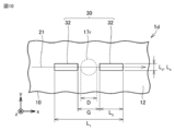
- Embodiment 4 The biological component measuring device 1d according to the fourth embodiment will be described with reference to FIGS. 9 and 10.
- the biological component measuring device 1d of the present embodiment has the same configuration as the biological component measuring device 1c of the third embodiment, but is mainly different in the following points.
- the high thermal conductive film 30 is separated from the entire irradiated portion 17r in the first direction (x direction) in the plan view of the sample mounting surface (second surface 12).
- the high thermal conductive film 30 includes a plurality of high thermal conductive film portions 32.
- the plurality of high thermal conductive film portions 32 are arranged in the first direction (x direction) with a gap G from each other.
- the irradiated portion 17r is located between a pair of high thermal conductive film portions 32 adjacent to each other.
- the pair of high thermal conductive film portions 32 adjacent to each other are on both sides of the first direction (x direction) (specifically, the positive first direction (+ x direction) side and the negative first direction (specifically, the positive first direction (+ x direction) side) with respect to the irradiation portion 17r. It is provided on the (-x direction) side).
- the distance G between the pair of high thermal conductive film portions 32 adjacent to each other is equal to or larger than the diameter D of the irradiated portion 17r. Specifically, the interval G is larger than the diameter D of the irradiated portion 17r.
- the plurality of high thermal conductive film portions 32 are separated from the irradiation portion 17r in the first direction ( ⁇ x direction).
- the interval G may be 2.0 times or less or 1.5 times or less the diameter D of the irradiated portion 17r.
- the third length L 3 of each of the plurality of high thermal conductive film portions 32 in the first direction (x direction) is the fourth length L 4 of each of the plurality of high thermal conductive film portions 32 in the second direction (y direction). It is larger than (second length L 2 of the high thermal conductive film 30).
- Each of the plurality of high thermal conductive film portions 32 spreads the heat generated from the sample 5 irradiated with the excitation light 17 in the first direction (x direction) rather than the second direction (y direction).
- the third length L 3 of each of the plurality of high thermal conductive film portions 32 in the first direction (x direction) may be larger than the diameter D of the irradiated portion 17r.
- the fourth length L 4 of each of the plurality of high thermal conductive film portions 32 in the second direction (y direction) may be smaller than the diameter D of the irradiated portion 17r.
- the high thermal conductive film 30 is different from the material forming the high thermal conductive material of the first embodiment.
- the high thermal conductive film 30 is made of a metal such as gold or copper.
- the high thermal conductive film 30 spreads the heat generated from the sample 5 irradiated with the excitation light 17 in the first direction (x direction) rather than the second direction (y direction). Therefore, the change in temperature of the portion (temperature gradient region 19) of the optical medium 10 in the optical path of the probe light 21 becomes large.
- the change in the refractive index of the portion of the optical medium 10 (refractive index gradient region 18) in the optical path of the probe light 21 becomes large.
- the displacement amount ⁇ of the probe light 21 detected by the optical position detector 25 becomes large. Therefore, the biological component measuring device 1d can measure the biological component with improved accuracy.
- the third length L 3 of each of the plurality of high thermal conductive film portions 32 is 80 ⁇ m, and the plurality of high thermal conductive films in the second direction (y direction).
- the fourth length L 4 of each of the film portions 32 is 20 ⁇ m, the thickness of each of the plurality of high thermal conductive film portions 32 is 10 ⁇ m, and the interval G is 40 ⁇ m.
- the diameter D of the excitation light 17 is 40 ⁇ m, and the width of the probe light 21 is 20 ⁇ m.
- the biological component measuring device 1d of the present embodiment exerts the following effects in addition to the effects of the biological component measuring device 1c of the third embodiment.
- the high thermal conductive film 30 includes a plurality of high thermal conductive film portions 32.
- the plurality of high thermal conductive film portions 32 are separated from the irradiation portion 17r in the first direction ( ⁇ x direction).
- the high thermal conductive film 30 is separated from the entire irradiated portion 17r in the first direction (x direction). There is.
- the excitation light 17 incident on the irradiated portion 17r is irradiated to the sample 5, and the absorbed heat of the sample 5 increases.
- the high thermal conductive film 30 a material having a higher thermal conductivity but a lower transmittance with respect to the excitation light 17 can be used.
- the change in temperature of the portion (temperature gradient region 19) of the optical medium 10 in the optical path of the probe light 21 becomes even larger.
- the change in the refractive index of the portion of the optical medium 10 (refractive index gradient region 18) in the optical path of the probe light 21 becomes even larger.
- the displacement amount ⁇ of the probe light 21 detected by the optical position detector 25 becomes large.
- the biological component measuring device 1d makes it possible to measure biological components with improved accuracy.
- the high thermal conductive film 30 is made of metal. Therefore, the thermal conductivity of the high thermal conductive film 30 can be further increased.
- the change in temperature of the portion (temperature gradient region 19) of the optical medium 10 in the optical path of the probe light 21 becomes even larger.
- the change in the refractive index of the portion of the optical medium 10 (refractive index gradient region 18) in the optical path of the probe light 21 becomes even larger.
- the displacement amount ⁇ of the probe light 21 detected by the optical position detector 25 becomes large.
- the biological component measuring device 1d makes it possible to measure biological components with improved accuracy.
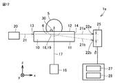
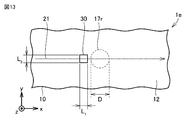
- Embodiment 5 The biological component measuring device 1e according to the fifth embodiment will be described with reference to FIGS. 12 and 13.
- the biological component measuring device 1e of the present embodiment has the same configuration as the biological component measuring device 1 of the first embodiment, but differs mainly in the following points.
- the high thermal conductive film 30 is arranged asymmetrically with respect to the irradiated portion 17r in the first direction (x direction) in a plan view of the sample mounting surface (second surface 12). In a plan view of the sample mounting surface (second surface 12), the high thermal conductive film 30 is separated from the entire irradiated portion 17r in the first direction (x direction).
- the high thermal conductive film 30 is provided only on one side (for example, the negative first direction ( ⁇ x direction) side) of the irradiation portion 17r in the first direction (x direction).
- the first length L 1 of the high thermal conductive film 30 in the first direction (x direction) may be equal to or greater than the second length L 2 of the high thermal conductive film 30 in the second direction (y direction). Specifically, the first length L 1 may be larger than the second length L 2.
- the first length L 1 may be smaller than the diameter D of the irradiated portion 17r, or may be smaller than the diameter D of the irradiated portion 17r.
- the first length L 1 may be larger than the diameter D of the irradiated portion 17r.
- the high thermal conductive film 30 is made of a metal such as gold or copper, as in the fourth embodiment.
- the high thermal conductive film 30 spreads the heat generated from the sample 5 irradiated with the excitation light 17 in the first direction (x direction) rather than the second direction (y direction). Therefore, the change in temperature of the portion (temperature gradient region 19) of the optical medium 10 in the optical path of the probe light 21 becomes large.
- the change in the refractive index of the portion of the optical medium 10 (refractive index gradient region 18) in the optical path of the probe light 21 becomes large.
- the displacement amount ⁇ of the probe light 21 detected by the optical position detector 25 becomes large. Therefore, the biological component measuring device 1e can measure the biological component with improved accuracy.
- the first length L 1 of the high heat conductive film 30 is 20 ⁇ m
- the second length L 2 of the high heat conductive film 30 is 20 ⁇ m, which means that the high heat is high.
- the thickness of the conductive film 30 is 10 ⁇ m
- the distance between the high thermal conductive film 30 and the irradiated portion 17r is 10 ⁇ m.
- the diameter D of the excitation light 17 is 40 ⁇ m
- the width of the probe light 21 is 20 ⁇ m.
- the biological component measuring device 1f of the modified example of the present embodiment will be described.
- the high thermal conductive film 30 overlaps a part of the irradiated portion 17r in the plan view of the sample mounting surface (second surface 12).
- the biological component measuring devices 1e and 1f of the present embodiment have the same effects as those of the biological component measuring device 1 of the first embodiment.
- the high thermal conductive film 30 is arranged asymmetrically with respect to the irradiated portion 17r in the first direction in a plan view of the sample mounting surface (second surface 12). ing. Therefore, the change in temperature of the portion (temperature gradient region 19) of the optical medium 10 in the optical path of the probe light 21 becomes large. The change in the refractive index of the portion of the optical medium 10 (refractive index gradient region 18) in the optical path of the probe light 21 becomes large. The displacement amount ⁇ of the probe light 21 detected by the optical position detector 25 becomes large.
- the biological component measuring devices 1e and 1f make it possible to measure biological components with improved accuracy.
- the high thermal conductive film 30 is separated from the entire irradiated portion 17r in the first direction (x direction). There is. Therefore, all the excitation light 17 incident on the irradiated portion 17r is irradiated to the sample 5, and the heat absorption of the sample 5 increases. Further, as the high thermal conductive film 30, a material having a higher thermal conductivity but a lower transmittance with respect to the excitation light 17 can be used. The change in temperature of the portion (temperature gradient region 19) of the optical medium 10 in the optical path of the probe light 21 becomes even larger.
- the change in the refractive index of the portion of the optical medium 10 (refractive index gradient region 18) in the optical path of the probe light 21 becomes even larger.
- the displacement amount ⁇ of the probe light 21 detected by the optical position detector 25 becomes large.
- the biological component measuring device 1e makes it possible to measure biological components with improved accuracy.
- the high thermal conductive film 30 is made of metal. Therefore, the thermal conductivity of the high thermal conductive film 30 can be further increased.
- the change in temperature of the portion (temperature gradient region 19) of the optical medium 10 in the optical path of the probe light 21 becomes even larger.
- the change in the refractive index of the portion of the optical medium 10 (refractive index gradient region 18) in the optical path of the probe light 21 becomes even larger.
- the displacement amount ⁇ of the probe light 21 detected by the optical position detector 25 becomes large.
- the biological component measuring devices 1e and 1f make it possible to measure biological components with improved accuracy.
- the biological component measuring device 1g according to the sixth embodiment will be described with reference to FIG.
- the biological component measuring device 1g of the present embodiment has the same configuration as the biological component measuring device 1 of the first embodiment, but is mainly different in the following points.
- the biological component measuring device 1g further includes an antireflection film 35 provided on the surface of the high thermal conductive film 30 distal to the optical medium 10.
- the antireflection film 35 reduces the reflection of the excitation light 17 generated at the interface between the sample 5 and the high thermal conductive film 30.
- the antireflection film 35 is zinc selenide (ZnSe), zinc sulfide (ZnS), calcium fluoride (CaF 2 ), magnesium fluoride (MgF 2 ), potassium bromide (KBr) or sodium chloride (NaCl) or any of these. It is formed by a combination.
- the biological component measuring device 1g of the present embodiment exerts the following effects in addition to the effect of the biological component measuring device 1 of the first embodiment.
- the biological component measuring device 1g of the present embodiment further includes an antireflection film 35 provided on the surface of the high thermal conductive film 30 distal to the optical medium 10. Therefore, more excitation light 17 is applied to the sample 5, and the heat absorption of the sample 5 increases.
- the change in temperature of the portion (temperature gradient region 19) of the optical medium 10 in the optical path of the probe light 21 becomes even larger.
- the change in the refractive index of the portion of the optical medium 10 (refractive index gradient region 18) in the optical path of the probe light 21 becomes even larger.
- the displacement amount ⁇ of the probe light 21 detected by the optical position detector 25 becomes large.
- the biological component measuring device 1 g makes it possible to measure biological components with improved accuracy.
- Embodiment 7 The biological component measuring device 1h according to the seventh embodiment will be described with reference to FIG.
- the biological component measuring device 1h of the present embodiment has the same configuration as the biological component measuring device 1 of the first embodiment and exhibits the same effect, but is mainly different in the following points.
- the third surface 13 is tilted with respect to the incident direction of the probe light 21.
- the fourth surface 14 is inclined with respect to the emission direction of the probe light 21.
- the exit direction of the probe light 21 to the optical medium 10 may be parallel to the incident direction of the probe light 21 to the optical medium 10.
- the optical medium 10 is, for example, an internal total internal reflection prism (TIR prism).
- the probe light 21 is incident on the optical medium 10 from the third surface 13 of the optical medium 10.
- the probe light 21 is refracted by the third surface 13 and travels through the optical medium 10 toward the interface between the optical medium 10 (second surface 12) and the sample 5.
- the optical path of the probe light 21 in the optical medium 10 overlaps with the portion of the sample mounting surface (second surface 12) irradiated by the excitation light 17.
- the probe light 21 is totally internally reflected at the interface between the optical medium 10 (second surface 12) and the high thermal conductive film 30. While the probe light 21 travels through the optical medium 10, the probe light 21 travels through the refractive index gradient region 18 generated in the optical medium 10 by the heat absorbed by the sample 5.
- the probe light 21 is refracted in the refractive index gradient region 18, and the traveling direction of the probe light 21 changes.
- the probe light 21 (first exit probe light 21a, second exit probe light 21b) is emitted from the fourth surface 14 of the optical medium 10.
- Bio component measuring device 5 samples, 6 surfaces, 10 optical media, 11 1st surface, 12 2nd surface, 13 3rd surface, 14 4th surface Surface, 16 excitation light source, 17 excitation light, 17r irradiation part, 18 refractive index gradient region, 19 temperature gradient region, 20 probe light source, 21 probe light, 21a first exit probe light, 21b second exit probe light, 22a first Position, 22b 2nd position, 25 optical position detector, 27 displacement amount calculation unit, 28 biological component measurement unit, 30 high heat conductive film, 31, 32 high heat conductive film part, 33 opening, 35 antireflection film.
Landscapes
- Physics & Mathematics (AREA)
- Health & Medical Sciences (AREA)
- General Health & Medical Sciences (AREA)
- Chemical & Material Sciences (AREA)
- Analytical Chemistry (AREA)
- Biochemistry (AREA)
- Life Sciences & Earth Sciences (AREA)
- General Physics & Mathematics (AREA)
- Immunology (AREA)
- Pathology (AREA)
- Spectroscopy & Molecular Physics (AREA)
- Nuclear Medicine, Radiotherapy & Molecular Imaging (AREA)
- Investigating Or Analyzing Materials Using Thermal Means (AREA)
- Investigating, Analyzing Materials By Fluorescence Or Luminescence (AREA)
Priority Applications (5)
| Application Number | Priority Date | Filing Date | Title |
|---|---|---|---|
| CN202080097731.6A CN115190968B (zh) | 2020-03-04 | 2020-03-04 | 生物体成分测定装置 |
| PCT/JP2020/009073 WO2021176583A1 (ja) | 2020-03-04 | 2020-03-04 | 生体成分測定装置 |
| JP2020543133A JP6786027B1 (ja) | 2020-03-04 | 2020-03-04 | 生体成分測定装置 |
| US17/790,508 US12222288B2 (en) | 2020-03-04 | 2020-03-04 | Biological component measurement apparatus |
| DE112020006830.7T DE112020006830T5 (de) | 2020-03-04 | 2020-03-04 | Messvorrichtung für biologische komponenten |
Applications Claiming Priority (1)
| Application Number | Priority Date | Filing Date | Title |
|---|---|---|---|
| PCT/JP2020/009073 WO2021176583A1 (ja) | 2020-03-04 | 2020-03-04 | 生体成分測定装置 |
Publications (1)
| Publication Number | Publication Date |
|---|---|
| WO2021176583A1 true WO2021176583A1 (ja) | 2021-09-10 |
Family
ID=73219999
Family Applications (1)
| Application Number | Title | Priority Date | Filing Date |
|---|---|---|---|
| PCT/JP2020/009073 Ceased WO2021176583A1 (ja) | 2020-03-04 | 2020-03-04 | 生体成分測定装置 |
Country Status (5)
| Country | Link |
|---|---|
| US (1) | US12222288B2 (https=) |
| JP (1) | JP6786027B1 (https=) |
| CN (1) | CN115190968B (https=) |
| DE (1) | DE112020006830T5 (https=) |
| WO (1) | WO2021176583A1 (https=) |
Cited By (3)
| Publication number | Priority date | Publication date | Assignee | Title |
|---|---|---|---|---|
| JP7205002B1 (ja) * | 2022-02-17 | 2023-01-16 | 三菱電機株式会社 | 非侵襲物質分析装置 |
| JP7466817B1 (ja) * | 2023-07-19 | 2024-04-12 | 三菱電機株式会社 | 分析装置 |
| JP7638461B1 (ja) * | 2024-08-21 | 2025-03-03 | 三菱電機株式会社 | 非侵襲物質分析装置及び非侵襲物質分析方法 |
Families Citing this family (5)
| Publication number | Priority date | Publication date | Assignee | Title |
|---|---|---|---|---|
| WO2022185454A1 (ja) * | 2021-03-03 | 2022-09-09 | 三菱電機株式会社 | 成分測定装置および成分測定方法 |
| JP6956930B1 (ja) * | 2021-03-23 | 2021-11-02 | 三菱電機株式会社 | 生体成分測定装置および生体成分測定方法 |
| CN118679373A (zh) * | 2022-02-17 | 2024-09-20 | 三菱电机株式会社 | 非侵入式物质分析装置 |
| JP2024112539A (ja) | 2023-02-08 | 2024-08-21 | 株式会社東芝 | センシングシステム、及び反射光学素子 |
| JP7736944B1 (ja) * | 2024-04-16 | 2025-09-09 | 三菱電機株式会社 | 生体成分測定装置 |
Citations (9)
| Publication number | Priority date | Publication date | Assignee | Title |
|---|---|---|---|---|
| JPS61137047A (ja) * | 1984-12-10 | 1986-06-24 | Canon Inc | 光散乱計測装置 |
| JPS6239731A (ja) * | 1985-08-16 | 1987-02-20 | Canon Inc | 薄膜の光物性測定装置 |
| JPH06308095A (ja) * | 1993-04-21 | 1994-11-04 | Hitachi Ltd | 光熱変位信号検出方法とその装置 |
| JP2009158926A (ja) * | 2007-12-07 | 2009-07-16 | Canon Inc | 電磁波発生素子、電磁波集積素子、及び電磁波検出装置 |
| US20100157316A1 (en) * | 2006-11-21 | 2010-06-24 | Maris Humphrey J | Picosecond ultrasonic system incorporating an optical cavity |
| JP2017519214A (ja) * | 2014-06-16 | 2017-07-13 | ディアモンテク、ゲゼルシャフト、ミット、ベシュレンクテル、ハフツングDiamontech Gmbh | 非侵襲物質分析 |
| WO2018123169A1 (ja) * | 2016-12-26 | 2018-07-05 | 三菱電機株式会社 | 生体物質測定装置および生体物質測定方法 |
| JP2019507319A (ja) * | 2015-12-09 | 2019-03-14 | ディアモンテク、ゲゼルシャフト、ミット、ベシュレンクテル、ハフツングDiamontech Gmbh | 物質を分析するための装置及び方法 |
| WO2019150543A1 (ja) * | 2018-02-02 | 2019-08-08 | 三菱電機株式会社 | 生体物質測定装置 |
Family Cites Families (10)
| Publication number | Priority date | Publication date | Assignee | Title |
|---|---|---|---|---|
| US4682897A (en) * | 1984-12-10 | 1987-07-28 | Canon Kabushiki Kaisha | Light scattering measuring apparatus |
| JPH06273328A (ja) * | 1993-03-22 | 1994-09-30 | Kyoto Electron Mfg Co Ltd | 屈折率測定方法及びその装置 |
| JP3844688B2 (ja) * | 2000-12-25 | 2006-11-15 | 富士写真フイルム株式会社 | 全反射減衰を利用したセンサー |
| JP2002277376A (ja) * | 2001-03-16 | 2002-09-25 | Toshiba Corp | 近接場光プローブおよび近接場光記録再生装置 |
| JP2004286578A (ja) * | 2003-03-20 | 2004-10-14 | Asahi Kasei Corp | 反射型熱レンズ分光分析装置 |
| JP4701739B2 (ja) * | 2005-02-17 | 2011-06-15 | パナソニック株式会社 | 蛍光測定装置 |
| JP5553717B2 (ja) * | 2010-09-17 | 2014-07-16 | 富士フイルム株式会社 | 光電場増強デバイスを用いた光の測定方法および測定装置 |
| DE102014113134A1 (de) * | 2014-09-11 | 2015-07-23 | Rofin-Baasel Lasertech Gmbh & Co. Kg | Optische Einrichtung |
| EP3248544B1 (en) * | 2015-01-21 | 2021-12-08 | National Institutes for Quantum Science and Technology | Device for measuring concentration of substance in blood, and method for measuring concentration of substance in blood |
| WO2019110084A1 (de) * | 2017-12-04 | 2019-06-13 | Diamontech Gmbh | Vorrichtung und verfahren zum analysieren eines stoffs |
-
2020
- 2020-03-04 JP JP2020543133A patent/JP6786027B1/ja active Active
- 2020-03-04 WO PCT/JP2020/009073 patent/WO2021176583A1/ja not_active Ceased
- 2020-03-04 US US17/790,508 patent/US12222288B2/en active Active
- 2020-03-04 CN CN202080097731.6A patent/CN115190968B/zh active Active
- 2020-03-04 DE DE112020006830.7T patent/DE112020006830T5/de active Pending
Patent Citations (9)
| Publication number | Priority date | Publication date | Assignee | Title |
|---|---|---|---|---|
| JPS61137047A (ja) * | 1984-12-10 | 1986-06-24 | Canon Inc | 光散乱計測装置 |
| JPS6239731A (ja) * | 1985-08-16 | 1987-02-20 | Canon Inc | 薄膜の光物性測定装置 |
| JPH06308095A (ja) * | 1993-04-21 | 1994-11-04 | Hitachi Ltd | 光熱変位信号検出方法とその装置 |
| US20100157316A1 (en) * | 2006-11-21 | 2010-06-24 | Maris Humphrey J | Picosecond ultrasonic system incorporating an optical cavity |
| JP2009158926A (ja) * | 2007-12-07 | 2009-07-16 | Canon Inc | 電磁波発生素子、電磁波集積素子、及び電磁波検出装置 |
| JP2017519214A (ja) * | 2014-06-16 | 2017-07-13 | ディアモンテク、ゲゼルシャフト、ミット、ベシュレンクテル、ハフツングDiamontech Gmbh | 非侵襲物質分析 |
| JP2019507319A (ja) * | 2015-12-09 | 2019-03-14 | ディアモンテク、ゲゼルシャフト、ミット、ベシュレンクテル、ハフツングDiamontech Gmbh | 物質を分析するための装置及び方法 |
| WO2018123169A1 (ja) * | 2016-12-26 | 2018-07-05 | 三菱電機株式会社 | 生体物質測定装置および生体物質測定方法 |
| WO2019150543A1 (ja) * | 2018-02-02 | 2019-08-08 | 三菱電機株式会社 | 生体物質測定装置 |
Cited By (7)
| Publication number | Priority date | Publication date | Assignee | Title |
|---|---|---|---|---|
| JP7205002B1 (ja) * | 2022-02-17 | 2023-01-16 | 三菱電機株式会社 | 非侵襲物質分析装置 |
| WO2023157164A1 (ja) * | 2022-02-17 | 2023-08-24 | 三菱電機株式会社 | 非侵襲物質分析装置 |
| US12292400B2 (en) | 2022-02-17 | 2025-05-06 | Mitsubishi Electric Corporation | Non-invasive substance analysis apparatus |
| JP7466817B1 (ja) * | 2023-07-19 | 2024-04-12 | 三菱電機株式会社 | 分析装置 |
| WO2025017856A1 (ja) * | 2023-07-19 | 2025-01-23 | 三菱電機株式会社 | 分析装置 |
| JP7638461B1 (ja) * | 2024-08-21 | 2025-03-03 | 三菱電機株式会社 | 非侵襲物質分析装置及び非侵襲物質分析方法 |
| WO2026042194A1 (ja) * | 2024-08-21 | 2026-02-26 | 三菱電機株式会社 | 非侵襲物質分析装置及び非侵襲物質分析方法 |
Also Published As
| Publication number | Publication date |
|---|---|
| JPWO2021176583A1 (https=) | 2021-09-10 |
| CN115190968B (zh) | 2026-03-17 |
| US20230053065A1 (en) | 2023-02-16 |
| US12222288B2 (en) | 2025-02-11 |
| CN115190968A (zh) | 2022-10-14 |
| DE112020006830T5 (de) | 2022-12-15 |
| JP6786027B1 (ja) | 2020-11-18 |
Similar Documents
| Publication | Publication Date | Title |
|---|---|---|
| JP6786027B1 (ja) | 生体成分測定装置 | |
| EP0627620B1 (en) | Method for measuring internal information in scattering medium and apparatus for the same | |
| JP3107927B2 (ja) | 散乱吸収体の光学情報計測装置及び方法 | |
| US7236814B2 (en) | Optical member for biological information measurement, biological information calculation apparatus, biological information calculation method, computer-executable program, and recording medium | |
| US6128091A (en) | Element and apparatus for attenuated total reflection measurement, and method for measuring specific component using the same | |
| JP6985561B2 (ja) | 生体成分測定装置 | |
| JP5581222B2 (ja) | 被検体の血液中の物質の濃度の非侵襲的測定のための装置および方法 | |
| US11067451B2 (en) | Photo-detection system comprising photo-detection apparatus including light-shielding film, optically-coupled layer, and photodetector and arithmetic circuit | |
| JP4047903B2 (ja) | 生体情報測定用光学素子およびそれを用いた生体情報測定装置 | |
| JPH05261109A (ja) | 光ct画像装置 | |
| JP2011511694A (ja) | 網膜から逆反射された光を使用して、血液中の物質濃度を非侵襲的に測定する装置および方法 | |
| US9332936B2 (en) | Concentration determination apparatus and concentration determination method for detecting an absorbance of living body tissue based on a light intensity and measuring a concentration of a measured component contained in living body tissue | |
| CN1838911A (zh) | 使用波长路由器从电磁波谱中测量分析物 | |
| CN100496396C (zh) | 测量生物信息的光学元件以及利用该元件的生物信息测量装置 | |
| JP7476317B2 (ja) | 非侵襲物質分析装置 | |
| JPWO2020158348A1 (ja) | 血糖値測定装置および血糖値測定方法 | |
| JP2013088138A (ja) | 屈折率測定装置および濃度測定装置並びにその方法 | |
| Chandra Shekar et al. | Detection of melanoma cancer cell by designing a SPR based biosensor | |
| JP7736944B1 (ja) | 生体成分測定装置 | |
| JP7205002B1 (ja) | 非侵襲物質分析装置 | |
| JP4047904B2 (ja) | 生体情報測定用光学素子およびそれを用いた生体情報測定装置 | |
| JP7466817B1 (ja) | 分析装置 | |
| JP2003240709A (ja) | 特定成分の濃度測定方法及びそれに用いる濃度測定用接触子 | |
| JP2000136997A (ja) | 光計測装置 | |
| Fedorin et al. | Development of a simulation tool for optimal design of a mobile photoplethysmography sensor |
Legal Events
| Date | Code | Title | Description |
|---|---|---|---|
| ENP | Entry into the national phase |
Ref document number: 2020543133 Country of ref document: JP Kind code of ref document: A |
|
| 121 | Ep: the epo has been informed by wipo that ep was designated in this application |
Ref document number: 20922572 Country of ref document: EP Kind code of ref document: A1 |
|
| 122 | Ep: pct application non-entry in european phase |
Ref document number: 20922572 Country of ref document: EP Kind code of ref document: A1 |