WO2021166030A1 - 防振装置及び空気調和機の室外機 - Google Patents
防振装置及び空気調和機の室外機 Download PDFInfo
- Publication number
- WO2021166030A1 WO2021166030A1 PCT/JP2020/006062 JP2020006062W WO2021166030A1 WO 2021166030 A1 WO2021166030 A1 WO 2021166030A1 JP 2020006062 W JP2020006062 W JP 2020006062W WO 2021166030 A1 WO2021166030 A1 WO 2021166030A1
- Authority
- WO
- WIPO (PCT)
- Prior art keywords
- vibration
- housing
- fixing member
- vibration isolator
- bent
- Prior art date
- Legal status (The legal status is an assumption and is not a legal conclusion. Google has not performed a legal analysis and makes no representation as to the accuracy of the status listed.)
- Ceased
Links
Images













Classifications
-
- F—MECHANICAL ENGINEERING; LIGHTING; HEATING; WEAPONS; BLASTING
- F16—ENGINEERING ELEMENTS AND UNITS; GENERAL MEASURES FOR PRODUCING AND MAINTAINING EFFECTIVE FUNCTIONING OF MACHINES OR INSTALLATIONS; THERMAL INSULATION IN GENERAL
- F16F—SPRINGS; SHOCK-ABSORBERS; MEANS FOR DAMPING VIBRATION
- F16F15/00—Suppression of vibrations in systems; Means or arrangements for avoiding or reducing out-of-balance forces, e.g. due to motion
- F16F15/02—Suppression of vibrations of non-rotating, e.g. reciprocating systems; Suppression of vibrations of rotating systems by use of members not moving with the rotating systems
- F16F15/04—Suppression of vibrations of non-rotating, e.g. reciprocating systems; Suppression of vibrations of rotating systems by use of members not moving with the rotating systems using elastic means
- F16F15/08—Suppression of vibrations of non-rotating, e.g. reciprocating systems; Suppression of vibrations of rotating systems by use of members not moving with the rotating systems using elastic means with rubber springs ; with springs made of rubber and metal
-
- F—MECHANICAL ENGINEERING; LIGHTING; HEATING; WEAPONS; BLASTING
- F04—POSITIVE - DISPLACEMENT MACHINES FOR LIQUIDS; PUMPS FOR LIQUIDS OR ELASTIC FLUIDS
- F04B—POSITIVE-DISPLACEMENT MACHINES FOR LIQUIDS; PUMPS
- F04B39/00—Component parts, details, or accessories, of pumps or pumping systems specially adapted for elastic fluids, not otherwise provided for in, or of interest apart from, groups F04B25/00 - F04B37/00
- F04B39/0027—Pulsation and noise damping means
- F04B39/0044—Pulsation and noise damping means with vibration damping supports
-
- F—MECHANICAL ENGINEERING; LIGHTING; HEATING; WEAPONS; BLASTING
- F16—ENGINEERING ELEMENTS AND UNITS; GENERAL MEASURES FOR PRODUCING AND MAINTAINING EFFECTIVE FUNCTIONING OF MACHINES OR INSTALLATIONS; THERMAL INSULATION IN GENERAL
- F16F—SPRINGS; SHOCK-ABSORBERS; MEANS FOR DAMPING VIBRATION
- F16F1/00—Springs
- F16F1/36—Springs made of rubber or other material having high internal friction, e.g. thermoplastic elastomers
- F16F1/3615—Springs made of rubber or other material having high internal friction, e.g. thermoplastic elastomers with means for modifying the spring characteristic
-
- F—MECHANICAL ENGINEERING; LIGHTING; HEATING; WEAPONS; BLASTING
- F16—ENGINEERING ELEMENTS AND UNITS; GENERAL MEASURES FOR PRODUCING AND MAINTAINING EFFECTIVE FUNCTIONING OF MACHINES OR INSTALLATIONS; THERMAL INSULATION IN GENERAL
- F16F—SPRINGS; SHOCK-ABSORBERS; MEANS FOR DAMPING VIBRATION
- F16F1/00—Springs
- F16F1/36—Springs made of rubber or other material having high internal friction, e.g. thermoplastic elastomers
- F16F1/373—Springs made of rubber or other material having high internal friction, e.g. thermoplastic elastomers characterised by having a particular shape
- F16F1/376—Springs made of rubber or other material having high internal friction, e.g. thermoplastic elastomers characterised by having a particular shape having projections, studs, serrations or the like on at least one surface
-
- F—MECHANICAL ENGINEERING; LIGHTING; HEATING; WEAPONS; BLASTING
- F16—ENGINEERING ELEMENTS AND UNITS; GENERAL MEASURES FOR PRODUCING AND MAINTAINING EFFECTIVE FUNCTIONING OF MACHINES OR INSTALLATIONS; THERMAL INSULATION IN GENERAL
- F16F—SPRINGS; SHOCK-ABSORBERS; MEANS FOR DAMPING VIBRATION
- F16F2230/00—Purpose; Design features
- F16F2230/0041—Locking; Fixing in position
-
- F—MECHANICAL ENGINEERING; LIGHTING; HEATING; WEAPONS; BLASTING
- F16—ENGINEERING ELEMENTS AND UNITS; GENERAL MEASURES FOR PRODUCING AND MAINTAINING EFFECTIVE FUNCTIONING OF MACHINES OR INSTALLATIONS; THERMAL INSULATION IN GENERAL
- F16F—SPRINGS; SHOCK-ABSORBERS; MEANS FOR DAMPING VIBRATION
- F16F2230/00—Purpose; Design features
- F16F2230/0052—Physically guiding or influencing
- F16F2230/0058—Physically guiding or influencing using inserts or exterior elements, e.g. to affect stiffness
Definitions
- This disclosure relates to an outdoor unit of an air conditioner equipped with a vibration isolator and a vibration isolator.
- the natural frequency of the entire support structure of the vibration source is increased by attaching a fixing member to the vibration isolation member that supports the vibration source such as a compressor, and the piping is generated by vibration during transportation.
- a fixing member to the vibration isolation member that supports the vibration source such as a compressor
- the piping is generated by vibration during transportation.
- the present disclosure has been made to solve the above-mentioned problems, and an object of the present disclosure is to obtain a vibration isolator that simplifies the work of removing the fixing member.
- the vibration isolator according to the present disclosure includes a vibration isolator that is provided on the bottom plate of the housing inside the housing having a slit portion, supports a vibration source having an electric motor, and includes an elastic body in its configuration. It is provided with a fixing member that can be removed from the outside of the housing through the slit portion and is provided so as to fix the vibration isolator inside the housing.
- the vibration isolator according to the present disclosure can easily change the natural frequency of the entire support structure of the vibration source by simplifying the work of removing the fixing member provided so as to fix the vibration isolator. It has the effect of.
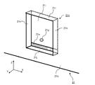
- FIG. It is a perspective view which shows the appearance of the outdoor unit of the air conditioner of Embodiment 1.
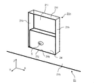
- FIG. It is a front view which shows the inside after installation of the outdoor unit of the air conditioner of Embodiment 1.
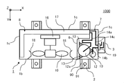
- FIG. It is a top view which shows the inside after installation of the outdoor unit of the air conditioner of Embodiment 1.
- FIG. It is a top view of the main part which shows the vibration isolation device of Embodiment 1.
- FIG. It is sectional drawing and top view for demonstrating the fixing member of the vibration isolation device of Embodiment 1.
- FIG. It is a top view of the main part which shows the 1st modification of the vibration isolation device of Embodiment 1.
- FIG. 1 It is sectional drawing of the main part which shows the 2nd modification of the vibration isolation device of Embodiment 1.
- FIG. It is sectional drawing of the main part which shows the 3rd modification of the vibration isolation device of Embodiment 1.
- FIG. It is sectional drawing of the main part which shows the vibration isolation device of Embodiment 2.
- FIG. It is sectional drawing of the main part which shows the state after replacing the fixing member of the vibration isolation device of Embodiment 2.
- It is a main part perspective view for demonstrating the modification of the vibration isolation device of Embodiment 2.
- Embodiment 1 The vibration isolator and the outdoor unit of the air conditioner according to the first embodiment will be described with reference to FIGS. 1 to 6.
- a vibration source having an electric motor in the housing for example, an outdoor unit of a water heater, is used.
- a vibration isolator may be provided in a device other than the outdoor unit of the air conditioner as long as it is provided.
- the XYZ Cartesian coordinates are defined so that the Z direction is the vertical direction and the XY plane is the horizontal plane. Further, when a positive or negative sign is attached to the direction, it will be described below assuming that the + X, + Y and + Z directions indicate the arrow directions of the Cartesian coordinates shown in each figure.
- the + Z direction may be described as "up” and the -Z direction as "down”, but the downward direction, that is, the -Z direction is not limited to the direction in which gravity acts, for example, gravity acts.
- the configuration may be such that the direction is the + Z direction.
- FIG. 1 is a perspective view showing the appearance of the outdoor unit 1000 of the air conditioner of the present embodiment
- FIG. 2 is a front view of the inside of the outdoor unit 1000 as viewed from the + Y direction
- FIG. 3 is the inside of the outdoor unit 1000. Is a top view seen from the + Z direction.
- FIG. 1 shows the state at the time of shipment and transportation before the outdoor unit 1000 is installed
- FIGS. 2 and 3 show the state after the outdoor unit 1000 is installed on the installation surface and the fixing member 4 is removed. show.
- the states at the time of shipment and at the time of transportation before the outdoor unit 1000 is installed shall be shown.
- the outdoor unit 1000 has a rectangular parallelepiped housing 1 including a bottom plate 1a, a front panel 1b, a side panel 1c including a rear surface side, and a top plate 1d.
- Two legs 2 are provided on the lower side of the bottom plate 1a of the body 1, and a side cover 3 is provided on one surface of the side panel 1c on the + X side.
- a part of the fixing member 4 is inserted into the slit portion 1e provided in the front panel 1b of the housing 1, and the fixing member 4 is fixed to the front panel 1b from the outside of the housing 1 by a screw 5 as a fastening member.
- the front panel 1b of the housing 1 is provided with a blower portion 1f that allows the air inside the outdoor unit 1000 to be blown to the outside by a fan 10 provided inside the housing 1.
- the inside of the housing 1 of the outdoor unit 1000 is divided into a machine room 7 and a fan room 8 by a separator 6.
- the separator 6 is a plate-shaped partition provided by bending inside the housing 1, and the + X side of the separator 6 is the machine room 7 and the ⁇ X side is the fan room 8. There is.
- the compressor 12 as a vibration source having an electric motor, a plurality of anti-vibration members 13 provided so as to support the support portion 12a of the compressor 12 on the bottom plate 1a of the housing 1, and the compressor 12
- the refrigerant pipes 14a, 14b, 14c connected to the above, and the control board 15 for performing operation control are provided.
- a fan 10 a fan support 16 for supporting the fan 10, an outdoor heat exchanger 17, and a bell mouth 18 mounted inside the front panel 1b are provided.
- the block-shaped foundation 90 for mounting the outdoor unit 1000 on the installation surface via the legs 2 and the bolt 91 for fixing the legs 2 to the foundation 90 are not included in the configuration of the outdoor unit 1000. ..
- the housing 1 includes a bottom plate 1a, a front panel 1b, a side panel 1c, and a top plate 1d.
- the side panel 1c constitutes three of the four side surfaces of the rectangular parallelepiped housing 1 except for one surface of the front panel 1b provided on the + Y side.
- the front panel 1b has a slit portion 1e in which the X direction for inserting the fixing member 4 is the longitudinal direction, and a fastening hole 1g through which the screw 5 penetrates (in FIGS. 1 to 3). (Not shown) is provided. Further, as shown in FIG.
- a bell mouth 18 is attached to the inside of the front panel 1b so as to surround the fan 10, and it is necessary to move the front panel 1b in the + Y direction in order to remove the front panel 1b. be.
- the top plate 1d is provided so as to cover the upper side of the housing 1, and the front panel 1b can be removed after the top plate 1d is removed.
- the compressor 12 is a vibration source that has an electric motor and generates vibration during operation. As shown in FIGS. 2 and 3, the compressor 12 has a support portion 12a, and the support portion 12a is vibration-proof supported by the vibration-proof member 13 on the bottom plate 1a of the housing 1 in the machine room 7. ing. Further, the compressor 12 is connected to the outdoor heat exchanger 17 by a refrigerant pipe 14a, and the compressor 12 and the outdoor heat exchanger 17 are each indoor heat exchangers of the indoor unit installed outside the outdoor unit 1000 (not shown). ) Is connected to the refrigerant pipes 14b and 14c.
- the refrigerant pipes 14b and 14c are taken out of the housing 1 from the machine room 7 via the flare connection portion 19, and after the outdoor unit 1000 is installed, the flare connection portion 19 and the refrigerant pipes on the indoor unit side (not shown) are connected. Be connected.
- the vibration source is a compressor
- the present invention is not limited to this, and the vibration source may be another one as long as it has an electric motor and generates vibration. ..
- the support portion 12a of the compressor 12 is vibration-proof supported by the vibration-proof member 13
- one or a plurality of vibration sources are pedestals.
- the vibration source may be mounted on the pedestal and supported by a vibration-proof member via a pedestal.
- the machine room 7 is provided with a control board 15 for controlling the operation of the outdoor unit 1000, and a power supply (not shown) is connected to the control board 15 from the outside of the outdoor unit 1000. Will be done.
- the side cover 3 attached to the side panel 1c of the housing 1 is provided so as to cover the power supply connection portion (not shown) and the flare connection portion 19 of the control board 15.
- the side cover 3 may also serve as a handle for transporting and installing the outdoor unit 1000.
- the machine room 7 is provided with an expansion valve for reducing the pressure of the refrigerant, a four-way valve for switching the flow direction of the refrigerant, a liquid reservoir for adjusting the circulation amount of the refrigerant, and repair. Parts that enhance the functionality of the outdoor unit 1000 may be installed, such as a service port in which the piping is branched in order to take in and out the refrigerant gas in the piping at the time.
- the fan chamber 8 is provided with a fan 10 for promoting heat exchange by the outdoor heat exchanger 17 and a fan support 16 for supporting the fan 10. Further, as shown in FIG. 3, the fan chamber 8 is provided with a bell mouth 18 for rectifying the wind generated by the fan 10.
- the separator 6 is installed so as not to block the air passage of the outdoor heat exchanger 17.
- FIG. 4 is a top view of a main part showing the vibration isolator 100 seen from the + Z direction
- FIG. 5 is a cross-sectional view of the main part showing the vibration isolator 100 seen from the + X direction
- 6 (A) is a cross-sectional view showing the fixing member 4 of the vibration isolator 100
- FIG. 6 (B) is a top view showing the fixing member 4
- FIG. 6 (C) shows the fixing member 4 on the vibration isolating member 13. It is a top view which shows the attached state.
- the support portion 12a of the compressor 12 as a vibration source having an electric motor is placed on the bottom plate 1a inside the housing 1 having the slit portion 1e in the front panel 1b. It is provided so as to be removable from the outside of the housing 1 through the anti-vibration member 13 and the slit portion 1e provided so as to support the housing 1, and is attached to the constricted portion 13a of the anti-vibration member 13 inside the housing 1. It is composed of a fixing member 4 and a screw 5 as a fastening member for fixing the fixing member 4 to the front panel 1b of the housing 1.
- the anti-vibration member 13 includes a stud 13b fixed on the bottom plate 1a of the housing 1, a rubber 13c which is an elastic body attached to the stud 13b and has a constricted portion 13a, and a stud 13b. It is composed of a stopper 13d attached to the upper part, that is, the threaded portion on the + Z side. That is, the anti-vibration member 13 includes an elastic body in its configuration.
- the anti-vibration member 13 supports the support portion 12a of the compressor 12 with the rubber 13c.
- the anti-vibration member 13 is positioned by fixing a rod-shaped stud 13b on the bottom plate 1a by welding and attaching a rubber 13c around the stud 13b. Further, by attaching the stopper 13d to the threaded portion at the tip of the stud 13b as a stepped bolt, it is possible to suppress the displacement of the compressor 12 in the Z-axis direction due to the impact during transportation and reduce the pipe breakage.
- the rubber 13c of the anti-vibration member 13 is formed of a synthetic rubber material. Since the rubber material has incompressibility, when a load is applied in the vertical direction, that is, in the Z direction, it tends to deform in the lateral direction, that is, in the XY plane. When there is no space for deformation in the XY plane, the deformation is suppressed, so that the displacement in the Z direction is also suppressed.
- the anti-vibration member 13 is considered as a spring, the amount of displacement with respect to the load becomes small, so that the spring constant increases. Therefore, the spring constant of the anti-vibration member 13 is related to the shape as well as the rigidity of the material itself.
- the constricted portion 13a is provided on the side surface of the vibration isolator member 13 to increase the surface area in the side surface direction and reduce the spring constant.
- the vibration isolating member 13 is not limited to this, and may have at least one constricted portion.
- the vibration isolator member 13 is described as having the rubber 13c as an elastic body, but the present invention is not limited to this, and the vibration isolator member 13 may be formed of, for example, a thermoplastic elastomer or the like. Any material may be included in the structure.
- the fixing member 4 is composed of a first plane portion 4c from one end 4a to the bent portion 4b and a second plane portion 4e from the bent portion 4b to the other end 4d, and has an L shape. It is formed in the shape of a bent plate. Further, the fixing member 4 has a first hole portion 4f for passing the screw 5 in the first plane portion 4c, and as shown in FIG. 6B, the second plane portion 4e has an arc shape in a plan view. It has a notch portion of 4 g.
- the fixing member 4 is formed in an L shape having one bent portion 4b
- the present invention is not limited to this, and for example, the fixing member 4 further has a bent portion on the 4a side. It may be a structure or the like. Further, the first plane portion 4c and the second plane portion 4e are not necessarily flat and may have a curved structure or the like.
- the second plane portion 4e is inserted into the slit portion 1e of the front panel 1b, and the notch portion 4g surrounds a part of the outer circumference of the constricted portion 13a of the vibration isolator member 13.
- the notch portion 4g of the fixing member 4 has an arc diameter having a shape along the constricted portion 13a of the rubber 13c of the vibration isolator member 13.
- the fixing member 4 can be positioned and the anti-vibration member 13 can be fixed.
- the fixing member 4 is fixed to the housing 1 by using screws 5 so that the first plane portion 4c is along the outer surface of the front panel 1b of the housing 1.
- the top view of the fixing member 4 provided in this way is as shown in FIG. 6 (C).
- the fixing member 4 can be mass-produced at low cost by using, for example, an L-shaped metal fitting formed by press working. Further, each panel of the housing 1 is not particularly limited, but when molded by press working, it is easy to form the slit portion 1e and the fastening hole 1g in the front panel 1b at the same time.
- the screw 5 is a tapping screw, and is attached through the first hole 4f of the fixing member 4 and the fastening hole 1g provided in the front panel 1b of the housing 1. As a result, the fixing member 4 is fastened and held along the front panel 1b of the housing 1.
- the screw 5 is not limited to a screw as long as it is a fastening member capable of fastening and holding the fixing member 4 to the housing 1, and for example, a bolt or the like may be used. However, in any case, the fastening member is provided so as to be removable from the outside of the housing.
- the compressor mounted on the outdoor unit of the air conditioner is the main vibration source of the outdoor unit.
- the compressor is provided with an electric motor for compressing the refrigerant, and during the operation of the compressor, vibration is generated due to a plurality of factors such as the mechanical operation of shaft rotation, the electromagnetic force of the electric motor, and the flow of the refrigerant.
- vibration is transmitted to the housing, a large noise may be generated from the sheet metal portion having a thin and wide area. Therefore, it is necessary to support the compressor with vibration isolation to suppress the vibration transmission to the floor surface.
- the compressor is connected to a refrigerant pipe that transports the refrigerant, but vibration is transmitted to the housing via the refrigerant pipe.
- the vibration of the pipe by the compressor causes not only noise but also strain in the pipe to generate stress, which may cause a problem such as pipe breakage.
- measures may be taken to extend the pipe length and reduce the rigidity by providing a folded portion in the pipe.
- a vibration-proof member for supporting the compressor with vibration isolation In order to absorb the operating vibration generated by such a compressor, a vibration-proof member for supporting the compressor with vibration isolation is provided.
- the anti-vibration member includes an elastic body in its composition, and when considering the vibration transmission of a spring / mass system of one degree of freedom, theoretically, the effect of vibration insulation is obtained from a frequency of ⁇ 2 times or more of the natural frequency.
- the effect of vibration insulation is determined by the frequency ratio of the natural frequency and the frequency of the exciting force. Therefore, in order to obtain the insulating effect of the operating vibration of the compressor, it is necessary to lower the natural frequency, and it is required to use a vibration isolator having a small spring constant. Therefore, by providing a constricted portion on the side surface of the anti-vibration member, the surface area of the anti-vibration member in the side surface direction can be increased and the spring constant can be lowered.
- the frequency band of the operating vibration of the compressor is different from the frequency band of the vibration received by the outdoor unit during transportation.
- the vibration received by the outdoor unit during transportation has an amplitude of 200 Hz or less, which is larger than the amplitude of other frequency bands.
- a particularly large vibration occurs at the natural frequency, and as a characteristic of vibration, the lower the frequency with respect to the same acceleration, the larger the displacement amount, the larger the strain amount, and the stress increases. Therefore, it is not desirable to reduce the natural frequency of the entire support structure including the compressor and the vibration isolator.
- the spring constant of the anti-vibration member can be increased by attaching a fixing member to suppress deformation of the anti-vibration member in the lateral direction.
- the rigidity of the fixing member itself attached to the anti-vibration member also increases the natural frequency due to the spring constant of the entire support structure including the compressor and the anti-vibration member. Therefore, it can be said that the natural frequency of the entire support structure can be adjusted by attaching the fixing member to the vibration isolator member.
- the fixing member is provided inside the housing, in order to remove the fixing member after transportation, it is necessary to remove the housing panel and reattach it.
- a small outdoor unit in order to reduce the number of parts, the number of divisions of the panels constituting the housing is reduced, and the fan chamber on the front side of the outdoor unit and the housing panel on the side of the machine room are integrated. It may be a structure.
- a top plate is assembled on the front panel and the side panel in order to eliminate a gap facing the upper surface so as to prevent rainwater from entering. Since the bell mouth is attached to the front panel of the housing, it is necessary to move it toward the front of the outdoor unit in order to remove the front panel. Therefore, since the front panel is removed after removing the top plate, the work process becomes complicated.
- the vibration isolator 100 and the outdoor unit 1000 of the present embodiment by providing the fixing member 4 as described above, the screw 5 is removed from the outside of the housing 1, and the fixing member 4 is simply pulled out to remove the screw 5. be able to. That is, since it is not necessary to remove and reattach the housing panel such as the front panel 1b, the removal work of the fixing member 4 can be simplified, and it is unique to the entire support structure including the compressor and the vibration isolator member. It has the effect of easily changing the frequency.
- the mounting state of the fixing member 4 can be visually confirmed from the outside of the housing 1, it is easy to check for forgetting to remove the fixing member 4.
- a space for securing the lengths of the refrigerant pipes 14a, 14b, 14c is required, but in order to remove the fixing member 4. It is not necessary to consider the workability inside the machine room 7. Further, since the fixing member 4 can be attached to the anti-vibration member 13 from the horizontal direction, that is, from the direction in the XY plane, it is not necessary to provide a space above the anti-vibration member 13. Therefore, it is possible to effectively utilize the installation area and reduce the size of the housing.
- the fixing member 4 is attached to only one of the three anti-vibration members 13 has been described. .. Even in such a case, by attaching the fixing member 4 to at least one of the plurality of anti-vibration members 13, the natural frequency of the entire support structure including the compressor 12 and the anti-vibration member 13 can be increased. Therefore, the natural frequency can be easily adjusted.
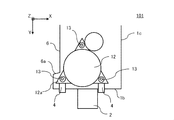
- FIG. 7 is a top view of a main part showing the vibration isolator 101 of the first modification of the vibration isolator 100 of the present embodiment.
- the vibration isolator 101 is provided with the lower portion of the separator 6 on the + Y side curved toward the fan chamber 8, the compressor 12 is installed in a different direction, and the fixing member 4 is further provided. Is attached to the two anti-vibration members 13, which is different from the anti-vibration device 100 of the present embodiment. Since the other configurations of the vibration isolator 101 are the same as those of the vibration isolator 100, the description thereof will be omitted.
- the anti-vibration device 101 a part of the support portion 12a of the compressor 12 is provided so as to be arranged on the curved portion 6a which is the curved portion of the separator 6, so that the anti-vibration member 13 is fixed to the two anti-vibration members 13. 4 can be attached. Therefore, although omitted in FIG. 7, the front panel 1b is provided with two slit portions 1e and two fastening holes 1g.
- the fixing member 4 can be provided for the plurality of anti-vibration members 13, it is unique to the entire support structure including the compressor 12 and the anti-vibration member 13. The effect of increasing the frequency becomes easier.
- the fixing member 4 is attached by inserting it into the slit portion 1e of the front panel 1b from the horizontal direction, that is, from the direction in the XY plane, only the lower portion of the separator 6 is curved and no space is provided above the vibration isolator member. Can be. Therefore, it is possible to effectively use the installation area and reduce the size of the housing.
- the separator is installed after installing the compressor and the piping, there is no problem in mounting the stud 13b and the stopper 13d of the vibration isolator member 13.
- FIG. 8 is a cross-sectional view of a main part showing the vibration isolator 102 of the second modification of the vibration isolator 100 of the present embodiment.
- the anti-vibration device 102 has a plurality of constricted portions 13a in the anti-vibration member 13, and a plurality of fixing members 4 with respect to the plurality of constricted portions 13a of one anti-vibration member 13. Is attached, which is different from the vibration isolator 100 of the present embodiment. Since the other configurations of the vibration isolator 102 are the same as those of the vibration isolator 100, the description thereof will be omitted.
- Each of the plurality of fixing members 4 has a first hole portion 4f in the first plane portion 4c. Then, one screw 5 penetrates the first hole portion 4f of the plurality of fixing members 4 and the fastening hole 1g of the front panel 1b and is fastened so that the fixing member 4 is along the front panel 1b of the housing 1. Is held. Therefore, the front panel 1b has a plurality of slit portions 1e for inserting the plurality of fixing members 4. Further, the plurality of fixing members 4 are formed into a shape that can be attached to separate constricted portions 13a having different heights by adjusting the lengths of the first plane portion 4c and the second plane portion 4e, respectively.
- the anti-vibration device 102 configured in this way, by attaching a plurality of fixing members 4 to a plurality of locations of the constricted portion 13a of the anti-vibration member 13, the effect of increasing the spring constant of the anti-vibration member 13 can be obtained. improves. Therefore, the spring constant of the anti-vibration member 13 itself can be lowered as compared with the case where one fixing member 4 is attached, and the anti-vibration effect of the operating vibration of the compressor 12 can be further improved.
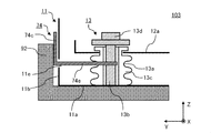
- FIG. 9 is a cross-sectional view of a main part showing the vibration isolator 103 of the third modification of the vibration isolator 100 of the present embodiment.
- the anti-vibration device 103 is in that the fixing member 74 is held by the packing member 92 along the front panel 11b of the housing 11 without using screws. Different from 100. Since the other configurations of the vibration isolator 103 are the same as those of the vibration isolator 100, the description thereof will be omitted.
- the fixing member 74 is attached to the front panel 11b because the surface opposite to the surface facing the front panel 11b of the housing 11, that is, the surface provided on the outside is in contact with the packing member 92. It is held along. Therefore, the fixing member 74 is different from the fixing member 4 of the vibration isolator 100 of the present embodiment in that the first plane portion 74c does not have a hole through which a fastening member such as a screw is penetrated.
- the packing member 92 is not included in the configuration of the outdoor unit provided with the vibration isolator 103 and the vibration isolator 103.
- the housing 11 is provided in a rectangular parallelepiped shape by a plurality of panels including a bottom plate 11a and a front panel 11b, and has a slit portion 11e into which a fixing member 74 is inserted into the front panel 11b. It is common with the housing 1. On the other hand, the housing 11 is different from the housing 1 in that the front panel 11b does not have a fastening hole through which a fastening member such as a screw penetrates.
- the fixing member 74 is a pipe due to vibration during transportation because the second plane portion 74e is attached to the constricted portion 13a of the vibration isolator 13. Since the purpose is to reduce breakage and the like, it is sufficient that the vibration isolator member 13 is attached to the vibration isolator member 13 at least during transportation. Then, in the outdoor unit provided with the vibration isolator 103, at the time of shipment and transportation, for example, a packing member made of styrofoam is attached to the upper and lower parts of the outdoor unit so as to cover the corners, and the outside thereof is covered with cardboard and fixed with a plastic band. It will be packed. Therefore, as shown in FIG.
- the packing member 92 formed of Styrofoam is provided at a position where the fixing member 74 can be held, so that the fixing member 74 can be provided without newly providing a fastening member such as a screw. It can be held during transportation of the outdoor unit.
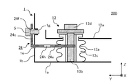
- FIG. 10 is a cross-sectional view of a main part showing the vibration isolator 200 of the present embodiment.
- 11 (A) is a cross-sectional view showing the fixing member 24 of the vibration isolator 200
- FIG. 11 (B) is a top view showing the fixing member 24,
- FIG. 11 (C) shows the fixing member 24 attached to the vibration isolating member 13. It is a top view which shows the state.
- FIG. 12 is a cross-sectional view of a main part showing a state after the fixing member 24 is replaced after the outdoor unit provided with the vibration isolator 200 is installed.
- the vibration isolator 200 of the present embodiment is different from the vibration isolator 100 of the first embodiment in that the fixing member 24 can be replaced. Since the other configurations of the vibration isolator 200 are the same as those of the vibration isolator 100, the description thereof will be omitted.
- the fixing member 24 has a first hole portion 24f in the first plane portion 24c from one end 24a to the bent portion 24b, and the fixing member 24 extends from the bent portion 24b to the other end 24d.
- the second plane portion 24e further has a second hole portion 24h.
- the second hole portion 24h is provided so as to be able to be attached by the screw 5, that is, to have a size through which the screw 5 can penetrate.
- the bent portion 24b to the other end 24d is formed longer than the one end 24a to the bent portion 24b, and the second plane portion 24e has a notched portion 24 g.
- the fixing member 4 is removed after the outdoor unit is installed and becomes an unnecessary part.
- the fixing member 24 is removed from the anti-vibration member 13, and the first flat portion 24c is inserted into the slit portion 1e. By fastening with screws 5, as shown in FIG. 12, it can be held along the front panel 1b.
- the vibration isolator 200 configured in this way, the slit portion 1e and the fastening hole 1g formed in the front panel 1b of the housing 1 are closed by reattaching the fixing member 24.
- FIG. 13 is a perspective view of a main part for explaining the shape of the housing 21 of the vibration isolator 201, which is a modification of the vibration isolator 200 of the present embodiment.
- FIG. 14 is a cross-sectional view of a main part showing the vibration isolator 201
- FIG. 15 is a perspective view of the main part showing the vibration isolator 201.
- FIG. 16 is a cross-sectional view of a main part showing a state after the fixing member 25 is replaced after the installation of the outdoor unit provided with the vibration isolator 201
- FIG. 17 is a perspective view of the main part.
- the vibration isolator 201 is different from the vibration isolator 200 of the present embodiment in that the housing 21 has a recess 21h for positioning the fixing member 24. Since the other configurations of the vibration isolator 201 are the same as those of the vibration isolator 200, the description thereof will be omitted.
- the recess 21h is formed in the front panel 21b of the housing 21.
- the recess 21h has a recessed surface 21i in which a slit portion 21e and a fastening hole 21g are formed and recessed in the internal direction of the housing 1, that is, in the ⁇ Y direction, and the recessed surface 21i to the housing 1 It is composed of a bent bottom surface 21j rising in an external direction, that is, a + Y direction, a bent side surface 21k, and a bent upper surface 21l.
- the bent side surfaces 21k are provided on two surfaces, and have a space substantially the same as the width of the fixing member 24 and face each other.
- the slit portion 21e is formed in the recess 21h at the lower portion of the recess surface 21i, that is, the portion on the ⁇ Z side. Therefore, when the second plane portion 24e of the fixing member 24 is inserted into the slit portion 21e, the second plane portion 24e of the fixing member 24 comes into contact with the bent bottom surface 21j in the horizontal direction, that is, as shown in FIGS. 14 and 15. It is guided and positioned in the direction in the XY plane.
- the fixing member 24 has a first hole portion 24f in the first plane portion 24c and a second hole portion 24h in the second plane portion 24e, respectively, as in the vibration isolator 200 of the present embodiment. .. Therefore, the fixing member 24 can be replaced after the outdoor unit is installed.
- the fixing member 24 is replaced, as shown in FIGS. 16 and 17, the second plane portion 24e of the fixing member 24 fits in the recess 21h of the front panel 1b, and the first plane portion 24c of the fixing member 24 is a bent bottom surface. By coming into contact with 21j, it is guided and positioned in the horizontal direction, that is, in the XY plane.
- the recessed surface 21i of the recess 21h is formed larger than the areas of the first plane portion 24c and the second plane portion 24e of the fixing member 24. Since each panel of the housing 21 including the front panel 21b is manufactured by press working and may be provided with irregularities in order to increase the rigidity, it is easy to provide the recesses 21h.
- the fixing member 24 when the fixing member 24 is inserted into the slit portion 21e of the front panel 21b, the fixing member 24 is guided in the horizontal direction by the bent bottom surface 21j of the recess 21h. This has the effect of facilitating the positioning of attaching the fixing member 24 to the anti-vibration member 13.
- the vibration isolator 201 can receive a load on the contact surface of the recess 21h with the bent bottom surface 21j against the vibration in the vertical direction, that is, the Z direction received by the fixing member 24 when the outdoor unit is transported.
- the effect is that the deformation of the front panel 21b of the housing 21 can be reduced by the dispersion of the above.
- the anti-vibration device 201 has been described as a modification of the anti-vibration device 200 of the present embodiment, for example, the housing 1 of the anti-vibration device 100 of the first embodiment may be provided with a recess. Needless to say, other embodiments and modifications can be combined as long as there is no contradiction.
- FIG. 18 is a cross-sectional view of a main part showing the vibration isolator 300 of the present embodiment.
- FIG. 19 is a cross-sectional view showing a fixing member 34 in the AA cross section of the vibration isolator 300 of FIG.
- the vibration isolator 300 of the present embodiment is implemented in that the fixing member 34 is attached so as to surround a part of the outer periphery of the stud 33b on the upper side of the rubber 33c of the vibration isolator 33. It is different from the vibration isolator 100 of the first embodiment. Since the other configurations of the anti-vibration device 300 are the same as those of the anti-vibration device 100, the description thereof will be omitted.
- the anti-vibration member 33 is attached to a rod-shaped stud 33b fixed on the bottom plate 1a of the housing 1, a rubber 33c attached to the periphery of the upper part of the stud 33b, that is, the + Z side is exposed, and a screw portion on the upper part of the stud 33b. It is composed of an attached stopper 33d. As shown in FIG. 18, the rubber 33c of the anti-vibration member 33 may be formed in a cylindrical shape having no constricted portion on the side surface, or may have a constricted portion, and the shape thereof is limited. Not done.
- the anti-vibration member 33 supports the support portion 12a of the compressor 12 with the rubber 33c.
- the fixing member 34 includes a first plane portion 34c from one end to the bent portion and a second plane portion 34e from the bent portion to the other end, similarly to the fixing member 4 provided in the vibration isolator 100 of the first embodiment.
- a first hole portion 34f is formed in the first plane portion 34c.
- the diameter of the fixing member 34 is adjusted so as to surround a part of the outer circumference of the stud 33b, and at least a part of the U-shaped notch portion 34g formed in an arc shape is formed. It is provided on the other end side of the two-plane portion 34e.
- the anti-vibration member 33 can be attached so as to be fixed by the notch portion 34g surrounding a part of the outer circumference of the stud 33b.
- the rigidity of the fixing member 34 mainly suppresses the vibration displacement of the compressor in the vertical direction.
- the rigidity of the fixing member 34 can be increased by increasing the thickness, for example.
- the anti-vibration device 300 configured in this way has the effect of being able to freely design the shape of the anti-vibration member 33. Further, by adjusting the rigidity of the fixing member 34, the natural frequency of the entire support structure including the compressor 12 and the vibration isolating member 33 can be increased, so that the design can be easily changed according to the required specifications. It plays the effect.
- FIG. 20 is a cross-sectional view of a main part showing the vibration isolator 301 of a modified example of the vibration isolator 300 of the present embodiment.
- FIG. 21 is a cross-sectional view of a main part showing a state when the fixing member 84 of the vibration isolator 301 is inserted.
- the shape of the other end side of the second plane portion 84e of the fixing member 84 of the vibration isolator 301 is different from that of the vibration isolator 300 of the present embodiment. Since the other configurations of the vibration isolator 301 are the same as those of the vibration isolator 300, the description thereof will be omitted.
- the fixing member 84 includes a first plane portion 84c from one end to the bent portion and a second plane portion 84e from the bent portion to the other end, similarly to the fixing member 34 provided in the vibration isolator 300 of the present embodiment.
- a first hole portion 84f is formed in the first plane portion 84c.
- the fixing member 84 is not shown because it is the same as the fixing member 34 of the vibration isolator 300 of the present embodiment and has a U-shaped notch on the other end side (similar to the notch 34g in FIG. 19). ).
- the other end of the second plane portion 84e of the fixing member 84 is tapered in the thickness direction of the second plane portion 84e, that is, in the Z direction. Therefore, as shown in FIG.
- the fixing member 84 is tilted in the Z direction when the fixing member 84 is inserted from the slit portion 1e of the housing 1, the fixing member 84 is inserted between the rubber 33c and the stopper 33d. Can be plugged in.
- the anti-vibration device 301 configured in this way has the effect of making it easier to attach the fixing member 84.
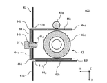
- FIG. 22 is a top view of a main part showing the vibration isolator 400 of the present embodiment.
- the fixing member 44 is attached so as to sandwich the side surface of the anti-vibration member 43, and the support rod 45a and the support plate as support members in contact with the fixing member 44 are attached. It differs from the vibration isolator 100 of the first embodiment in that 45b is provided. Since the other configurations of the vibration isolator 400 are the same as those of the vibration isolator 100, the description thereof will be omitted.
- the rubber 43c of the anti-vibration member 43 is formed in a cylindrical shape.
- the shape of the rubber 43c is not limited to this, and for example, a constricted portion may be provided, or the rubber 43c may be formed in a prismatic shape or the like.
- the anti-vibration member 43 may be formed of, for example, a rubber material which is an elastic body as a whole, or may have a structure in which an elastic body is partially provided.
- the fixing member 44 has a first plane portion 44c from one end 44a to the first bent portion 44b, and a second plane portion provided outside the housing 1 from the first bent portion 44b to the second bent portion 44d. It is composed of 44e and a third plane portion 44g from the second bent portion 44d to the other end 44f. Further, the first bent portion 44b and the second bent portion 44d are formed substantially vertically, and the first plane portion 44c and the third plane portion 44g face each other with the anti-vibration member 43 interposed therebetween. Further, a first hole portion 44h for attaching the screw 5 is formed in the second plane portion 44e.
- the support rod 45a is provided so as to be separated from the side surface of the anti-vibration member 43 and in contact with the first plane portion 44c of the fixing member 44. That is, the first plane portion 44c of the fixing member 44 is sandwiched between the support rod 45a and the vibration isolator 43.
- the support rod 45a is not limited to a rod-shaped support member as long as it can fix the first plane portion 44c of the fixing member 44 so as not to move in the X direction.
- the support plate 45b is provided so as to be separated from the side surface of the vibration isolator 43 and in contact with the third plane portion 44g of the fixing member 44. That is, the third plane portion 44g of the fixing member 44 is sandwiched between the support plate 45b and the vibration isolator 43. Further, the support rod 45a and the support plate 45b are provided so as to face each other with the anti-vibration member 43 interposed therebetween. A part of the separator 6 or a part of the housing 1 can be used as the support plate. Further, the support rod and the support plate may be replaced and installed, and the rod-shaped or plate-shaped one is not limited as long as each can be used as a support member.
- two slit portions 41e having a longitudinal direction in the Z direction are formed on the front panel 41b, and the first plane portion 44c and the third plane portion 44g of the fixing member 44 are formed on the two slit portions 41e. Each is plugged in. Further, in the front panel 41b of the housing 41, a fastening hole 41g is formed between the two slit portions 41e, and the first hole portion 44h and the fastening hole 41g of the second plane portion 44e of the fixing member 44 are formed. The fixing member 44 is held by penetrating and attaching the screw 5.
- the vibration isolator 400 configured in this way has the effect of suppressing lateral deformation of the vibration isolator 43 and increasing the spring constant. Further, since the shape of the anti-vibration member 43 is not limited, the effect of freely designing the anti-vibration member 43 can be obtained.
- the vibration isolator 400 since the first plane portion 44c and the third plane portion 44g of the fixing member 44 are in surface contact with the side surface of the vibration isolation member 43, a large contact area can be obtained. Therefore, the effect of suppressing the lateral deformation of the vibration isolator 43 is improved, and the spring constant can be further increased.
- FIG. 23 is a cross-sectional view of a main part showing the vibration isolator 500 of the present embodiment.
- FIG. 24 is a perspective view showing a fixing member 54 of the vibration isolator 500.
- the anti-vibration device 500 of the present embodiment is attached by inserting the fixing member 54 into the rubber 53c of the anti-vibration member 53 from the bottom plate 51a side of the housing 51. It is different from the vibration isolator 100 of the first embodiment. Since the other configurations of the vibration isolator 500 are the same as those of the vibration isolator 100, the description thereof will be omitted.
- the fixing member 54 is composed of a substrate portion 54a and two convex portions 54b, and the substrate portion 54a and the convex portion 54b are each formed in a plate shape.
- the number and shape of the convex portions 54b are not limited to those provided to two, and may be any number and shape required for fixing the vibration isolator member 53 and may be inserted from the bottom plate 1a side of the housing 1.
- the fixing member 54 can be easily molded by, for example, resin molding.
- the fixing member 54 is held by a packing member 92 provided outside the housing 51 from the lower side, that is, the ⁇ Z side.
- the packing member 92 is not included in the configuration of the vibration isolator 500 and the outdoor unit provided with the vibration isolator 500.
- the housing 51 has two slits 51e for inserting the convex portion 54b of the fixing member 54 into the bottom plate 51a. Since the slit portion 51e is provided for inserting the convex portion 54b of the fixing member 54 to fix the vibration isolator member 53, the shape thereof is as long as the convex portion 54b of the fixing member 54 is engaged. good.
- the anti-vibration member 53 is attached to the stud 53b fixed on the bottom plate 51a of the housing 51, the rubber 53c attached to the stud 53b, and the upper portion of the stud 53b, that is, the screw portion on the + Z side, similarly to the anti-vibration member 13. It is composed of the stopper 53d. As shown in FIG. 23, the rubber 53c of the anti-vibration member 53 has two recesses 53a formed on the bottom plate 1a side, and the convex portion 54b of the fixing member 54 is inserted into the recess 53a.
- the shape of the rubber 53c of the anti-vibration member 53 may be formed into, for example, a cylindrical shape having no constricted portion on the side surface, or may have a constricted portion, and the side surface shape is not limited.
- the vibration isolator 53 supports the support portion 12a of the compressor 12.
- the anti-vibration device 500 configured in this way has the effect of suppressing lateral deformation of the anti-vibration member 53 and increasing the spring constant. Further, since the side surface shape of the anti-vibration member 53 is not limited, the effect of freely designing the anti-vibration member 53 can be obtained. Further, since the convex portion 54b of the fixing member 54 is inserted into the concave portion 53a of the anti-vibration member 53, it is possible to reduce the detachment of the fixing member 54 during transportation.
- the fixing member 54 of the vibration isolator 500 can be attached to the vibration isolator 53 from the bottom plate 51a side of the housing 51, it is not necessary to provide a space around the vibration isolator 53. Therefore, it is possible to effectively utilize the installation area and reduce the size of the housing. Further, since the fixing member 54 can be attached to the plurality of anti-vibration members 53 regardless of the side surface shape of the housing 51, the attachment position of the compressor 12, and the like, the effect of further facilitating the adjustment of the natural frequency can be obtained.
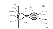
- FIG. 25 is a top view of a main part showing the vibration isolator 600 of the present embodiment
- FIG. 26 is a schematic view showing a fixing member 64 of the vibration isolator 600.
- the vibration isolator 600 of the present embodiment is implemented in that the fixing member 64 is formed in a clip shape and a separate member is not used to hold the fixing member 64. It is different from the vibration isolator 100 of the first embodiment. Since the other configurations of the vibration isolator 600 are the same as those of the vibration isolator 100, the description thereof will be omitted.
- the fixing member 64 includes a first portion 64c from one end 64a to a curved intermediate portion 64b, and a second portion from the intermediate portion 64b to the other end 64d provided inside the housing 1. It is composed of 64e. Further, the fixing member 64 has a constricted portion 64f formed so that a part of the first portion 64c and a part of the second portion 64e are close to each other, and is a clip having a spring force formed of, for example, metal or the like. It is a shaped member. As shown in FIGS.
- the fixing member 64 is inserted into the inside of the housing 1 from the front panel 1b side of the housing 1, and is between the constricted portion 64f and one end 64a and the constricted portion 64f and the other end.
- a gap with 64d is opened, and a part of the outer periphery of the side surface of the vibration isolator 63 is covered and sandwiched therein to fix the vibration isolator member 63.
- the housing 61 has two hole-shaped slits 61e for inserting the fixing member 64 into the front panel 61b. Further, between the two slit portions 1e, a curved portion 61 g curved so as to match the shape of the fixing member 64 is formed. If the fixing member 64 is stably attached, it is not necessary to provide the curved portion 61 g.
- the anti-vibration member 63 is formed in a cylindrical shape.
- the anti-vibration member 63 may be made of, for example, a rubber material which is an elastic body as a whole, or may have an elastic body in a part thereof.
- the anti-vibration member 63 has a constricted portion, and by attaching the fixing member 64 to the constricted portion, the fixing member 64 can be attached more stably.
- the anti-vibration device 600 configured in this way does not require a fastening member such as a screw and can be fixed to the anti-vibration member 63 by the spring force of the fixing member 64. It has the effect of saving labor in removal work and saving parts for fastening members.
Landscapes
- Engineering & Computer Science (AREA)
- General Engineering & Computer Science (AREA)
- Mechanical Engineering (AREA)
- Chemical & Material Sciences (AREA)
- Combustion & Propulsion (AREA)
- Physics & Mathematics (AREA)
- Acoustics & Sound (AREA)
- Aviation & Aerospace Engineering (AREA)
- Vibration Prevention Devices (AREA)
- Compressor (AREA)
Priority Applications (6)
| Application Number | Priority Date | Filing Date | Title |
|---|---|---|---|
| AU2020429601A AU2020429601B2 (en) | 2020-02-17 | 2020-02-17 | Vibration isolator and outdoor unit for air-conditioning apparatus |
| CN202080096306.5A CN115087818B (zh) | 2020-02-17 | 2020-02-17 | 防振装置以及空气调节机的室外机 |
| US17/789,531 US12247633B2 (en) | 2020-02-17 | 2020-02-17 | Vibration isolator and outdoor unit for air-conditioning apparatus |
| DE112020006761.0T DE112020006761T5 (de) | 2020-02-17 | 2020-02-17 | Schwingungsisolierung und Ausseneinheit für Klimaanlage |
| JP2022501405A JP7241956B2 (ja) | 2020-02-17 | 2020-02-17 | 防振装置及び空気調和機の室外機 |
| PCT/JP2020/006062 WO2021166030A1 (ja) | 2020-02-17 | 2020-02-17 | 防振装置及び空気調和機の室外機 |
Applications Claiming Priority (1)
| Application Number | Priority Date | Filing Date | Title |
|---|---|---|---|
| PCT/JP2020/006062 WO2021166030A1 (ja) | 2020-02-17 | 2020-02-17 | 防振装置及び空気調和機の室外機 |
Publications (1)
| Publication Number | Publication Date |
|---|---|
| WO2021166030A1 true WO2021166030A1 (ja) | 2021-08-26 |
Family
ID=77391496
Family Applications (1)
| Application Number | Title | Priority Date | Filing Date |
|---|---|---|---|
| PCT/JP2020/006062 Ceased WO2021166030A1 (ja) | 2020-02-17 | 2020-02-17 | 防振装置及び空気調和機の室外機 |
Country Status (6)
| Country | Link |
|---|---|
| US (1) | US12247633B2 (https=) |
| JP (1) | JP7241956B2 (https=) |
| CN (1) | CN115087818B (https=) |
| AU (1) | AU2020429601B2 (https=) |
| DE (1) | DE112020006761T5 (https=) |
| WO (1) | WO2021166030A1 (https=) |
Families Citing this family (1)
| Publication number | Priority date | Publication date | Assignee | Title |
|---|---|---|---|---|
| US20250121387A1 (en) * | 2023-10-16 | 2025-04-17 | Glorymakeup Inc. | Programmable Air Supply System with Liquid Cooling and Noise Suppression |
Citations (3)
| Publication number | Priority date | Publication date | Assignee | Title |
|---|---|---|---|---|
| JPS52153908U (https=) * | 1976-05-19 | 1977-11-22 | ||
| JPS58178541U (ja) * | 1982-05-26 | 1983-11-29 | 株式会社日立製作所 | 圧縮機の固定用ボルト |
| CN204986239U (zh) * | 2015-07-02 | 2016-01-20 | 珠海格力电器股份有限公司 | 一种压缩机减振安装结构 |
Family Cites Families (22)
| Publication number | Priority date | Publication date | Assignee | Title |
|---|---|---|---|---|
| JPH06249467A (ja) | 1993-02-26 | 1994-09-06 | Mitsubishi Heavy Ind Ltd | 空気調和機の室外ユニット |
| JP3224650B2 (ja) | 1993-10-01 | 2001-11-05 | 三菱重工業株式会社 | 空気調和機 |
| JPH09123938A (ja) * | 1995-10-31 | 1997-05-13 | Isuzu Motors Ltd | 自動車のボディマウント構造 |
| JPH1038027A (ja) | 1996-07-25 | 1998-02-13 | Mitsubishi Heavy Ind Ltd | 圧縮機の防振支持装置 |
| JP3707202B2 (ja) * | 1997-05-20 | 2005-10-19 | 株式会社富士通ゼネラル | 圧縮機の防振支持装置 |
| US6557816B2 (en) * | 2000-02-07 | 2003-05-06 | Fuji Photo Film Co., Ltd. | Motor mounting structure and drive shaft mounting structure |
| US6260373B1 (en) * | 2000-02-16 | 2001-07-17 | American Standard International Inc. | Heat exchanger with double vibration isolation |
| US6578682B2 (en) * | 2001-04-26 | 2003-06-17 | Honeywell International Inc. | Compact vibration isolation system for an inertial sensor assembly |
| JP2002340090A (ja) * | 2001-05-17 | 2002-11-27 | Matsushita Electric Ind Co Ltd | 防振装置 |
| CN100375848C (zh) * | 2003-06-17 | 2008-03-19 | 乐金电子(天津)电器有限公司 | 封闭型压缩机的减振装置 |
| KR20070069773A (ko) * | 2005-12-28 | 2007-07-03 | 삼성전자주식회사 | 압축기의 요동방지장치 |
| JP2009293813A (ja) * | 2008-06-02 | 2009-12-17 | Daikin Ind Ltd | 冷凍装置 |
| FR2980538B1 (fr) * | 2011-09-27 | 2013-10-25 | Thermodyn | Groupe moto-compresseur a cartouche amovible |
| JP2013137093A (ja) * | 2011-12-01 | 2013-07-11 | Aisin Seiki Co Ltd | 電動ポンプ |
| JP2013148236A (ja) * | 2012-01-17 | 2013-08-01 | Sharp Corp | 空気調和機の室外機、その他の防振装置付きの圧縮機を搭載した機器 |
| CN203009689U (zh) * | 2012-07-10 | 2013-06-19 | 株式会社久保田 | 减振装置及具有该减振装置的车辆 |
| JP6347645B2 (ja) * | 2014-03-31 | 2018-06-27 | 倉敷化工株式会社 | 防振支持装置 |
| WO2017119136A1 (ja) * | 2016-01-08 | 2017-07-13 | 三菱電機株式会社 | 圧縮機支持装置、冷凍サイクル装置の室外機、及び冷凍サイクル装置 |
| JP2018131933A (ja) | 2017-02-14 | 2018-08-23 | ダイキン工業株式会社 | 圧縮機の支持構造 |
| US10797559B2 (en) * | 2018-09-07 | 2020-10-06 | Denso International America, Inc. | Isolators for motors |
| CN109989904B (zh) * | 2019-04-08 | 2024-06-25 | 珠海格力电器股份有限公司 | 垫片、脚垫组件、压缩机及空调室外机 |
| US12104585B2 (en) * | 2021-07-23 | 2024-10-01 | Nokia Shanghai Bell Co., Ltd. | Vibration isolation to protect electrical circuits from vibration-induced damage |
-
2020
- 2020-02-17 WO PCT/JP2020/006062 patent/WO2021166030A1/ja not_active Ceased
- 2020-02-17 DE DE112020006761.0T patent/DE112020006761T5/de active Pending
- 2020-02-17 CN CN202080096306.5A patent/CN115087818B/zh active Active
- 2020-02-17 JP JP2022501405A patent/JP7241956B2/ja active Active
- 2020-02-17 AU AU2020429601A patent/AU2020429601B2/en active Active
- 2020-02-17 US US17/789,531 patent/US12247633B2/en active Active
Patent Citations (3)
| Publication number | Priority date | Publication date | Assignee | Title |
|---|---|---|---|---|
| JPS52153908U (https=) * | 1976-05-19 | 1977-11-22 | ||
| JPS58178541U (ja) * | 1982-05-26 | 1983-11-29 | 株式会社日立製作所 | 圧縮機の固定用ボルト |
| CN204986239U (zh) * | 2015-07-02 | 2016-01-20 | 珠海格力电器股份有限公司 | 一种压缩机减振安装结构 |
Also Published As
| Publication number | Publication date |
|---|---|
| JP7241956B2 (ja) | 2023-03-17 |
| DE112020006761T5 (de) | 2022-12-15 |
| CN115087818B (zh) | 2023-07-18 |
| JPWO2021166030A1 (https=) | 2021-08-26 |
| AU2020429601A1 (en) | 2022-07-14 |
| US20230052219A1 (en) | 2023-02-16 |
| AU2020429601B2 (en) | 2024-01-11 |
| US12247633B2 (en) | 2025-03-11 |
| CN115087818A (zh) | 2022-09-20 |
Similar Documents
| Publication | Publication Date | Title |
|---|---|---|
| JP2022147641A (ja) | 電動圧縮機 | |
| WO2013111356A1 (ja) | コンプレッサ用支持部材およびそれを用いたコンプレッサ | |
| WO2021166030A1 (ja) | 防振装置及び空気調和機の室外機 | |
| JP2017053553A (ja) | 冷凍空調装置 | |
| JP6288147B2 (ja) | 熱源ユニット | |
| JP2022524771A (ja) | ヒートポンプの熱源ユニット | |
| KR200404747Y1 (ko) | 천장판넬 고정구 | |
| JP5335399B2 (ja) | 空気調和装置における支持構造 | |
| KR100470580B1 (ko) | 공기 조화 장치 | |
| JPH08136008A (ja) | 空気調和機の室外機 | |
| JP2009109028A (ja) | 浴室換気空調装置 | |
| JPH0849883A (ja) | 空気調和機の室外機 | |
| KR200142858Y1 (ko) | 공기조화기의 방진장치 | |
| JP2011112324A (ja) | 空気調和機の室外機 | |
| JP2014066488A (ja) | 空気調和装置 | |
| KR200352554Y1 (ko) | 조립식 캐비넷의 코너 연결구조 | |
| KR200404749Y1 (ko) | 천장판넬 연결구 | |
| CN222228769U (zh) | 压缩机固定结构、室外机及暖通设备 | |
| JP2009186061A (ja) | 室外機及びこれを備えた空気調和装置 | |
| CN207865564U (zh) | 一种空调室外机 | |
| CN222703480U (zh) | 中隔板组件和空气源热泵空调 | |
| CN220107701U (zh) | 马达安装支架和空调室内机 | |
| JP6272110B2 (ja) | 車両用空気調和装置 | |
| JP2001065971A (ja) | 移動式シェルタ−の空調装置の取付構造 | |
| CN112747447A (zh) | 外壳结构及空调机组 |
Legal Events
| Date | Code | Title | Description |
|---|---|---|---|
| 121 | Ep: the epo has been informed by wipo that ep was designated in this application |
Ref document number: 20920148 Country of ref document: EP Kind code of ref document: A1 |
|
| ENP | Entry into the national phase |
Ref document number: 2022501405 Country of ref document: JP Kind code of ref document: A |
|
| ENP | Entry into the national phase |
Ref document number: 2020429601 Country of ref document: AU Date of ref document: 20200217 Kind code of ref document: A |
|
| 122 | Ep: pct application non-entry in european phase |
Ref document number: 20920148 Country of ref document: EP Kind code of ref document: A1 |
|
| WWG | Wipo information: grant in national office |
Ref document number: 17789531 Country of ref document: US |