WO2021140715A1 - 回転電機のステータ、回転電機、回転電機のステータの製造方法および、回転電機の製造方法 - Google Patents
回転電機のステータ、回転電機、回転電機のステータの製造方法および、回転電機の製造方法 Download PDFInfo
- Publication number
- WO2021140715A1 WO2021140715A1 PCT/JP2020/037755 JP2020037755W WO2021140715A1 WO 2021140715 A1 WO2021140715 A1 WO 2021140715A1 JP 2020037755 W JP2020037755 W JP 2020037755W WO 2021140715 A1 WO2021140715 A1 WO 2021140715A1
- Authority
- WO
- WIPO (PCT)
- Prior art keywords
- core
- stator
- coil
- winding
- electric machine
- Prior art date
Links
Images


Classifications
-
- H—ELECTRICITY
- H02—GENERATION; CONVERSION OR DISTRIBUTION OF ELECTRIC POWER
- H02K—DYNAMO-ELECTRIC MACHINES
- H02K15/00—Methods or apparatus specially adapted for manufacturing, assembling, maintaining or repairing of dynamo-electric machines
- H02K15/08—Forming windings by laying conductors into or around core parts
- H02K15/085—Forming windings by laying conductors into or around core parts by laying conductors into slotted stators
-
- H—ELECTRICITY
- H02—GENERATION; CONVERSION OR DISTRIBUTION OF ELECTRIC POWER
- H02K—DYNAMO-ELECTRIC MACHINES
- H02K3/00—Details of windings
- H02K3/04—Windings characterised by the conductor shape, form or construction, e.g. with bar conductors
-
- H—ELECTRICITY
- H02—GENERATION; CONVERSION OR DISTRIBUTION OF ELECTRIC POWER
- H02K—DYNAMO-ELECTRIC MACHINES
- H02K3/00—Details of windings
- H02K3/46—Fastening of windings on the stator or rotor structure
Definitions
- This application relates to a stator of a rotary electric machine, a method of manufacturing a rotary electric machine, a stator of a rotary electric machine, and a method of manufacturing a rotary electric machine.
- a stator used in a rotary electric machine such as an electric motor or a generator is composed of a stator core and a coil housed and mounted in a slot formed between the teeth of the stator core.
- the coil wire forming the coil is insulated and coated, and the coil is electrically insulated from the stator core.
- an insulating portion is further provided at a portion where the stator core and the coil are in contact with each other.
- Patent Document 1 As a conventional stator, a technique of winding a coil wire around three consecutive teeth at the same time has been proposed (see, for example, Patent Document 1).
- the crossover wire passes through the insulating member on the lower side. Be given.
- the winding is performed the third time.
- the number of turns of the coil is increased or decreased by half a turn, and an electric problem such as pulsation or vibration of a rotating electric machine occurs.
- the present application discloses a technique for solving the above-mentioned problems, and is capable of preventing interference of the crossovers of the stator and reducing electrical problems such as pulsation or vibration. It is an object of the present invention to provide a method for manufacturing a stator of an electric machine and a rotary electric machine, and a method for manufacturing a rotary electric machine.
- the stator of a rotary electric machine disclosed in the present application is A stator core in which a plurality of core portions having a yoke portion and a tooth portion formed so as to project radially inward from the central portion in the circumferential direction of the inner peripheral surface of the yoke portion are combined in an annular shape.
- a rotary electric machine provided with a coil formed by winding a coil wire around each of the plurality of teeth portions, and an insulating portion disposed between the core portion and the coil and insulating the stator core and the coil.
- the first winding frame as the insulating portion includes a first teeth end face covering portion that covers one end surface of the teeth portion in the axial direction of the portion around which the coil is wound, and a radial direction of the first teeth end face covering portion. It is connected to the outer end and is provided with a first outer collar that covers one end surface of the yoke portion in the axial direction and projects upward in the axial direction.
- the first outer collar is formed in the axial direction and has a first introduction groove portion for introducing the coil wire around which the coil is wound, and the coil wire formed in the axial direction and after winding the coil.
- the first lead-out groove portion that leads out to the outside in the radial direction of the stator core, It is provided with a plurality of guides extending in the circumferential direction and arranged in the axial direction, forming a plurality of groove portions each holding a plurality of crossovers connecting the coils of the different teeth portions.
- the rotary electric machine disclosed in the present application is With the stator of the rotary electric machine A rotor is provided inside the stator so as to face each other via a gap. Further, the method for manufacturing a stator of a rotary electric machine disclosed in the present application is described. The yoke portions of the plurality of core portions are deformed in a straight line, and the yoke portions are deformed linearly.
- the method for manufacturing a rotary electric machine disclosed in the present application is to arrange rotors facing each other through a gap inside the stator manufactured by the method for manufacturing a stator of a rotary electric machine.
- FIG. 5 is a cross-sectional view perpendicular to the axial direction of the rotary electric machine according to the first embodiment.
- FIG. 5 is a cross-sectional view of the rotary electric machine according to the first embodiment, which is cut by a plane passing through the axis of the rotating shaft.
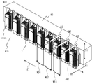
- FIG. 5 is a rear view showing a state in which the stator of the rotary electric machine according to the first embodiment is cut open and rotated in a straight line.
- It is a perspective view of the stator shown in FIG. 3, and is a view showing the back side of FIG. 3, that is, the inside of the stator.
- It is a perspective view which shows the structure of two kinds of core pieces constituting the stator core of the stator shown in FIG.
- FIG. It is a perspective view which shows the structure of the stator core by Embodiment 1.
- FIG. It is a top view of the core part by Embodiment 1.
- FIG. It is a perspective view which shows the structure of the 1st volume frame by Embodiment 1.
- FIG. It is a perspective view which shows the structure of the 4th winding frame by Embodiment 1.
- FIG. It is a perspective view which shows the state which the 1st winding frame and the 4th winding frame are attached to the core part by Embodiment 1.
- FIG. It is a figure which looked at the 1st core part in the direction of arrow A of FIG. It is a figure which looked at the 1st core part in the direction of arrow B of FIG.
- FIG. 1 It is a figure which looked at the 1st core part in the direction of arrow C of FIG. It is a figure which looked at the 1st core part in the direction of arrow D of FIG. It is a perspective view of the 2nd volume frame according to Embodiment 1.
- FIG. 2nd core part which attached the 2nd winding frame and the 4th winding frame by Embodiment 1 from the outside X1 in the radial direction X.
- FIG. It is a perspective view of the third volume frame according to Embodiment 1.
- FIG. It is a figure which looked at the 3rd core part which attached the 3rd winding frame and the 4th winding frame by Embodiment 1 from the outside X1 in the radial direction X.
- FIG. 1 It is a flowchart which shows the manufacturing process of the rotary electric machine by Embodiment 1. It is a flowchart which shows the manufacturing process of the coil by Embodiment 1. It is a development view of the stator in the coil forming process by Embodiment 1.
- FIG. It is a figure which shows the movement of the winding nozzle of the winding machine by Embodiment 1.
- FIG. It is a figure which shows the movement of the nozzles N1, N2, N3 after the formation of the coil of the 1st core part, the 2nd core part, and the 3rd core part by Embodiment 1.
- FIG. It is a conceptual diagram which shows the other winding method by Embodiment 1.
- FIG. 2 It is a perspective view which shows the state which the 1st winding frame, the 2nd winding frame, the 3rd winding frame, the 4th winding frame 254, and the film part are attached to the stator core by Embodiment 2.
- FIG. It is a perspective view which disassembled each member of FIG. It is a perspective view which shows the structure of the film part by Embodiment 2. It is a perspective view which shows the structure of the 1st volume frame by Embodiment 2.
- FIG. It is a perspective view of the first winding frame shown in FIG. 27A seen from the opposite side in the axial direction Y. It is a perspective view which shows the structure of the 4th winding frame by Embodiment 2.
- FIG. 5 is an enlarged plan view of a main part of the stator core according to the third embodiment. It is a perspective view of the core part by Embodiment 4. FIG. It is a perspective view which shows the state after winding of the stator according to Embodiment 4.
- FIG. 5 is an enlarged plan view of a main part of the stator core according to the third embodiment. It is a perspective view of the core part by Embodiment 4.
- FIG. It is a perspective view which shows the state after winding of the stator according to Embodiment 4.
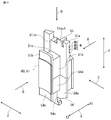
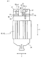
- FIG. 1 is a cross-sectional view of the rotary electric machine 100 perpendicular to the axial direction.
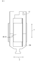
- FIG. 2 is a cross-sectional view of the rotor 20 of the rotary electric machine 100 cut along a plane passing through the axis of the rotary shaft 21.
- the rotary electric machine 100 includes a cylindrical frame 101, a bracket 103 that closes openings at both ends in the axial direction of the frame 101, a stator 10 fitted inside the frame 101, and the center of each of the two brackets 103.
- a rotor 20 is provided which is rotatably supported via a bearing (not shown) and whose outer peripheral surface is arranged so as to face the inner peripheral surface of the stator 10.
- a gap 107 exists between the outer peripheral surface of the rotor 20 and the inner peripheral surface of the stator 10.
- the permanent magnet 105 is embedded in the rotor core 22 fixed to the outer circumference of the rotating shaft 21 in a V shape, the permanent magnet may be arranged in a straight line or in another shape. Further, the permanent magnet may not be embedded, and may be attached to the outer peripheral surface of the rotor core 22 and arranged so as to face the inner peripheral surface of the stator 10.
- the directions of the stator 10 of the rotary electric machine 100 are the circumferential direction Z, the axial direction Y, and the radial direction X, respectively, based on a state in which the yoke portions 11a of the plurality of core portions 60 are arranged and combined in an annular shape.
- the outer side X1 in the radial direction X and the inner side X2 in the radial direction X are shown. Therefore, with respect to the stator 10, when each yoke portion 11a of each core portion 60 of the stator 10 is linearly rotated and deformed, or the protruding direction of each tooth portion 11b is reversed, that is, an annular stator.
- each direction is set with reference to the direction in which the yoke portion 11a of the stator 10 is arranged in an annular shape, which is the product state. , Will be described in each figure.
- the surface side perpendicular to the axial direction Y of the stator 10 and passing through the center of the stator 10 is “lower”, and the opposite is “upper”. ".
- the heights are compared according to the distance from the surface perpendicular to the axial direction Y of the stator 10 and passing through the center of the stator 10.
- the stator 10 includes a plurality of core portions 60 having a yoke portion 11a and a teeth portion 11b formed so as to project from the central portion of the inner peripheral surface of the yoke portion 11a in the circumferential direction Z to the inside X2 in the radial direction X.
- the stator core 11A combined in an annular shape, the coil 7 formed by winding a coil wire around each of the plurality of teeth portions 11b, and the core portion 60 and the coil 7 are arranged between each core portion 60 and the coil 7. It is provided with an insulating part that insulates the coil.
- the stator core 11A is a combination of nine core portions 60 connected together.
- FIG. 3 is a rear view showing a state in which the stator 10 of the rotary electric machine 100, which is originally annular, is cut open and deformed in a straight line, and is a view of the stator 10 viewed from the outer peripheral side.
- the respective core portions 60 are designated by reference numerals 61 to 69, and the first core portion 61 to the ninth core portion 69 will be described.
- FIG. 4 is a perspective view of the stator 10 shown in FIG. 3, and is a view showing the back side of FIG. 3, that is, the inside of the stator 10.
- FIG. 5 is a perspective view showing the configurations of two types of core pieces 11k1 and 11k2 constituting the stator core 11A of the stator 10 shown in FIG. FIG.
- FIG. 6 is a perspective view showing a configuration of a stator core 11A formed by alternately stacking a plurality of groups 11k1 and 11k2 of two types of core pieces shown in FIG. 5 in the axial direction Y, respectively.
- FIG. 7 is a plan view of the core portion 60.
- the stator 10 is located on the upper side of the paper surface as an insulating portion arranged to insulate the stator core 11A composed of a plurality of core portions 60, the coil 7, and the stator core 11A and the coil 7. It includes a first winding frame 51, a second winding frame 52, a third winding frame 53, and a fourth winding frame 54 on the lower side of the paper surface.
- the core portions 60 arranged in the circumferential direction Z are connected to the first core portion 61, the second core portion 62, the third core portion 63, and the fourth core from the winding start side of the first coil wire 71.
- the first winding frame 51 is used for the first core portion 61, the fourth core portion 64, and the seventh core portion 67, that is, the core portion 60 constituting the U phase.
- the second winding frame 52 is used for the second core portion 62, the fifth core portion 65, and the eighth core portion 68, that is, the core portion 60 constituting the V phase.
- the third volume frame 53 is used for the third core portion 63, the sixth core portion 66, and the ninth core portion 69, that is, the core portion 60 constituting the W phase, but the details of the difference will be described later. ..
- the stator core 11A is formed by punching a thin magnetic steel plate in a mold (not shown), and a plurality of core piece groups 11k1 and 11k2 shown in FIG. 5 are alternately formed in the axial direction Y as shown in FIG. It is formed by stacking. As a result, the stator core 11A is formed by connecting the yoke portions 11a of the first core portion 61 to the ninth core portion 69 by the connecting portions 111 provided at the ends in the circumferential direction Z. In FIG. 6, the stator core 11A is configured by nine first core portions 61 to ninety core portions 69 being linearly connected by a connecting portion 111.
- the yoke portions 11a of the adjacent core portions 60 can freely rotate.
- the stator core 11A can rotate in a straight line or in a reverse warp shape in which the direction in which the teeth portion 11b protrudes in the radial direction X is reversed.
- the stator coil is composed of three phases of U phase, V phase, and W phase, and has a star connection structure in which different phases are lined up for each core portion 60 connected in the circumferential direction Z.
- the first core portion 61 is the U phase (U1)
- the second core portion 62 is the V phase (V1)
- the third core portion 63 is the W phase (W1)
- the fourth core portion 64 is the U phase (U2).
- the fifth core portion 65 is the V phase (V2)
- the sixth core portion 66 is the W phase (W2)
- the seventh core portion 67 is the U phase (U3)
- the eighth core portion 68 is the V phase (V3)
- the ninth core portion 68 is wound around the core portion 69.
- each core portion 60 is provided with a coil 7, and an upper first winding frame 51, a second winding frame 52, a third winding frame 53, and a fourth winding frame 54 as insulating portions, respectively.
- the first core portion 61 to the ninth core portion 69 have a coil 7 in each core portion 60, FIG. 4 as an insulating portion, a first winding frame 51 on the upper side of the paper, a second winding frame 52, and a third winding. The description is adopted regardless of whether the frame 53 and the fourth volume frame 54 on the lower side of the same page are installed or not installed.
- the surface of the yoke portion 11a along the axial direction Y of the outer side X1 in the radial direction X is defined as the outer peripheral surface 113 of the yoke.
- the outer peripheral surface 113 of the yoke is formed with a first recess 114 extending in the axial direction Y at the center of the circumferential direction Z.
- the first recess 114 is used for positioning when the stator core 11A is attached to the winding machine forming the coil 7.
- the tooth portion 11b is provided with a shoe portion 11c protruding from the tip of the inner side X2 in the radial direction X in the circumferential direction Z, respectively.
- the surface of the yoke portion 11a inside X2 in the radial direction X along the axial direction Y is defined as the inner peripheral surface 112 of the yoke.
- Both sides of the teeth portion 11b along the axial direction Y at both ends in the circumferential direction Z are the side surface 121 of the teeth portion, and the surface of the tip of the inner X2 of the radial direction X of the teeth portion 11b along the axial direction Y is the inner peripheral surface 122 of the teeth portion.
- the surface of the shoe portion 11c along the axial direction Y of the outer side X1 of the radial direction X is referred to as the shoe portion outer peripheral surface 131.
- the region surrounded by the inner peripheral surface of the yoke 112, the side surface 121 of the teeth portion, and the outer peripheral surface 131 of the shoe portion becomes a slot 14 in which the coil wire 70 is wound to form the coil 7.
- the first winding frame 51 is a winding frame to be attached to the first core portion 61, the fourth core portion 64, and the seventh core portion 67.
- the first winding frame 51 is attached to the teeth portion 11b and the yoke portion 11a.
- the second winding frame 52 is a winding frame to be attached to the second core portion 62, the fifth core portion 65, and the eighth core portion 68.
- the second winding frame 52 is attached to the teeth portion 11b and the yoke portion 11a.
- the third winding frame 53 is a winding frame to be attached to the third core portion 63, the sixth core portion 66, and the ninth core portion 69.
- the third winding frame 53 is attached to the teeth portion 11b and the yoke portion 11a.
- FIG. 8 is a perspective view showing the configuration of the first winding frame 51 used for the stator 10 shown in FIGS. 3 and 4.
- the first winding frame 51 includes a tooth end face covering portion 51c (first tooth end face covering portion), an outer collar 51a (first outer collar), an inner collar 51b (first inner collar), and a slot side surface covering portion 51d ( A first slot side covering portion) is provided, and these are integrally formed.
- the tooth end face covering portion 51c covers one end surface of the tooth portion 11b in the axial direction Y of the portion around which the coil 7 is wound.
- the outer collar 51a is connected to the end of the outer X1 of the tooth end surface covering portion 51c in the radial direction X, covers one end surface of the yoke portion 11a in the axial direction Y, and projects upward in the axial direction Y.
- the inner collar 51b is connected to the end of the inner X2 of the tooth end surface covering portion 51c in the radial direction X, and connects the inner tip portion of the one end surface of the tooth portion 11b in the axial direction Y and the one end surface of the shoe portion 11c in the axial direction Y. Cover and project upward in the axial direction Y.
- the slot side surface covering portion 51d covers the tooth portion side surface 121 of the teeth portion 11b, the yoke inner peripheral surface 112 of the yoke portion 11a, and the shoe portion outer peripheral surface 131 of the shoe portion 11c.
- the slot side surface covering portion 51d projects downward from the tooth end surface covering portion 51c, the outer collar 51a, and the inner collar 51b.
- the slot side surface covering portion 51d covers half of each surface constituting the slot 14 in the axial direction Y.
- FIG. 9 is a perspective view showing the configuration of the fourth winding frame 54 used for the stator 10 shown in FIGS. 3 and 4.
- the fourth winding frame 54 is an insulating member on the lower side of the paper surface of the stator 10 shown in FIG.
- the fourth winding frame 54 includes a tooth end face covering portion 54c (second tooth end face covering portion), an outer collar 54a (second outer collar), an inner collar 54b (second inner collar), and a slot side covering portion 54d ( A second slot end face covering portion) is provided, and these are integrally formed.
- the tooth end face covering portion 54c covers the other end surface of the tooth portion 11b in the axial direction Y of the portion around which the coil 7 is wound.
- the outer collar 54a is connected to the end of the outer X1 of the tooth end surface covering portion 54c in the radial direction X, covers the other end surface of the yoke portion 11a in the axial direction Y, and projects upward in the axial direction Y.
- the inner flange 54b is connected to the end of the inner X2 of the tooth end surface covering portion 54c in the radial direction X, and connects the inner tip portion of the other end surface of the tooth portion 11b in the axial direction Y and the other end surface of the shoe portion 11c in the axial direction Y. Cover and project upward in the axial direction Y.
- the slot side surface covering portion 54d covers the tooth portion side surface 121 of the teeth portion 11b, the yoke inner peripheral surface 112 of the yoke portion 11a, and the shoe portion outer peripheral surface 131 of the shoe portion 11c.
- the slot side surface covering portion 54d projects downward from the tooth end surface covering portion 54c, the outer collar 54a, and the inner collar 54b.
- the slot side surface covering portion 54d covers half of each surface constituting the slot 14 in the axial direction Y. Therefore, the slot side surface covering portion 51d of the first winding frame 51 and the slot side surface covering portion 54d of the fourth winding frame 54 can cover the entire surface of each side surface constituting the slot 14.
- the first winding frame 51 and the fourth winding frame 54 are attached to each core portion 60 so as to fit into the inner peripheral surface of the slot 14 from both sides in the axial direction.
- the first winding frame 51 and the fourth winding frame 54 electrically insulate the coil 7 from each core portion 60.
- the first winding frame 51 and the fourth winding frame 54 are formed, for example, by injection molding of an insulating resin.
- the length of the slot side covering portion 51d of the first winding frame 51 and the length of the slot side covering portion 54d of the fourth winding frame 54 in the axial direction are formed to be substantially the same length.
- the present invention is not limited to this, and the length of each axial direction Y can be changed as appropriate, and it is sufficient that all the side surfaces constituting the slot 14 can be covered.
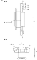
- FIG. 10 is a perspective view showing a state in which the first winding frame 51 and the fourth winding frame 54 are attached to the first core portion 61.
- FIG. 11 is a view of the first core portion 61 to which the first winding frame 51 and the fourth winding frame 54 shown in FIG. 10 are mounted from the outside X1 in the radial direction X, that is, the first core portion 61 is shown in FIG.
- FIG. 12 is a view of the first core portion 61 to which the first winding frame 51 and the fourth winding frame 54 shown in FIG. 10 are mounted from the inside X2 in the radial direction X, that is, the first core portion 61 is shown in FIG. It is a figure seen in the direction of arrow B.
- 13A is a view of the first core portion 61 to which the first winding frame 51 and the fourth winding frame 54 shown in FIG. 10 are mounted from the circumferential direction Z, that is, the first core portion 61 is in the arrow C direction of FIG. It is a figure seen in.
- FIG. 13B is a view of the first core portion 61 to which the first winding frame 51 and the fourth winding frame 54 shown in FIG. 10 are mounted from the axial direction Y, that is, the first core portion 61 is in the arrow D direction of FIG. It is a figure seen in.
- groove portions M extending in the circumferential direction Z are formed in a plurality of steps in the axial direction Y on the outer peripheral surface of the outer X1 in the radial direction X of the outer collar 51a. ..
- the groove portion M is formed in three stages of a first groove portion M1, a second groove portion M2, and a third groove portion M3 from the upper side away from the core portion 60 in the axial direction Y. That is, the first groove portion M1, the second groove portion M2, and the third groove portion M3 are formed parallel to the circumferential direction Z and arranged in the axial direction Y at different heights.
- the first groove portion M1 is formed on the outer peripheral surface of the outer flange 51a between the first guide G1 and the second guide G2 provided in the circumferential direction Z.
- the second groove portion M2 is formed on the outer peripheral surface of the outer flange 51a between the second guide G2 and the third guide G3 provided in the circumferential direction Z.
- the third groove portion M3 is formed on the outer peripheral surface of the outer flange 51a between the third guide G3 and the fourth guide G4 provided in the circumferential direction Z. Therefore, the first guide G1 to the fourth guide G4 are also formed at different heights in parallel with the circumferential direction Z and in the axial direction Y. As shown in FIG.
- the first guide G1 is provided on both sides of the lead-out groove portion 51out (first lead-out groove portion) described later in the circumferential direction Z and in the circumferential direction of the introduction groove portion 51in (first introduction groove portion) described later. Since it is provided only in the vicinity of one edge of Z, the first groove portion M1 is formed only on both sides of the lead-out groove portion 51out in the circumferential direction Z and in the vicinity of one edge of the introduction groove portion 51in in the circumferential direction Z. Become.
- the second groove portion M2 and the third groove portion M3 intermittently continue in the circumferential direction Z.
- the first groove portion M1, the second groove portion M2, and the third groove portion M3 are used to hold a plurality of crossover lines 70J connecting the coils 7 of the different tooth portions 11b in parallel in the circumferential direction.
- the crossover line 70J is a continuous line between the coils 7.
- the introduction groove portion 51in formed in the outer flange 51a in the axial direction Y allows the coil wire 70 to be wound from the outer side X1 in the radial direction X of the stator core 11A to the inner side X2 in the radial direction X in order to wind the coil 7 around the teeth portion 11b. It is the entrance to introduce to.
- the lead-out groove portion 51out formed in the outer flange 51a in the axial direction Y winds the coil wire 70 around the teeth portion 11b to form the coil 7, and the coil wire 70 is formed from the inner side X2 of the stator core 11A in the radial direction X to the radial direction X. It is an exit leading to the outer side X1.
- the lead-out groove portion 51out is inclined so that the lower end portion of the side surface of the crossover line 70J on the crossover direction side is located closer to the crossover direction side of the crossover line 70J than the upper end portion.
- the lead-out groove portion 51out formed on the outer flange 51a of the first winding frame 51 is connected to the first groove portion M1 provided on the left side in the circumferential direction Z of the lead-out groove portion 51out at the lower portion.
- the height of the lower portion of the lead-out groove portion 51out and the height of the upper surface of the second guide G2 constituting the lower surface of the first groove portion M1 are set to be the same height. That is, the lower portion of the lead-out groove portion 51out and the upper surface of the second guide G2 are flush with each other.
- FIG. 14 is a perspective view of the second volume frame 52.
- FIG. 15 is a view of the second core portion 62 to which the second winding frame 52 and the fourth winding frame 54 are mounted as viewed from the outer side X1 in the radial direction X. Since the basic configuration of the second volume frame 52 is the same as that of the first volume frame 51, only different parts will be described.
- a second guide G2 provided intermittently in the circumferential direction Z on the outer collar 51a of the first winding frame 51 is provided on the outer flange 52a of the outer flange 52a in the circumferential direction Z. It is provided only in the central portion, and is not provided at both end portions in the circumferential direction Z.
- the second guide G2 does not exist on both sides of the lead-out groove portion 52out (second lead-out groove portion) in the circumferential direction Z, and the first groove portion M1 and the second groove portion M2 in the first winding frame 51 are integrated. ..
- the lead-out groove portion 52out formed on the outer flange 52a of the second winding frame 52 is set to have the same height as the upper surface of the third guide G3. That is, the lower portion of the lead-out groove portion 52out and the upper surface of the third guide G3 are flush with each other.
- FIG. 16 is a perspective view of the third volume frame 53.
- FIG. 17 is a view of the third core portion 63 to which the third winding frame 53 and the fourth winding frame 54 are mounted as viewed from the outer side X1 in the radial direction X. Since the basic configuration of the third volume frame 53 is the same as that of the first volume frame 51, only different parts will be described.
- the second guide G2 and the third guide G3 which are intermittently provided on the outer collar 51a of the first winding frame 51 in the circumferential direction Z, are provided on the outer collar 52a. It is provided only in the central portion of the circumferential direction Z, and these guides are not provided at both end portions of the circumferential direction Z.
- the second groove portion M2 and the third groove portion M3 do not exist on both sides of the lead-out groove portion 53out (third lead-out groove portion) in the circumferential direction Z, and the first groove portion M1, the second groove portion M2, and the third groove portion M3 in the first winding frame 51 do not exist.
- the three groove portions M3 are integrated. The same applies to the outside of the introduction groove portion 53in (third introduction groove portion) in the circumferential direction Z.
- the lead-out groove portion 53out formed on the outer flange 53a of the third winding frame 53 is set so that the lower portion is at the same height as the upper surface of the fourth guide G4. That is, the lower portion of the lead-out groove portion 53out and the upper surface of the fourth guide G4 are flush with each other.
- the coil wire 70 is a wire for forming the coil 7.
- the three coil wires 70 of the first coil wire 71, the second coil wire 72, and the third coil wire 73 are used.
- the portion where the coil 7 starts winding is the first winding start wire 711, the second winding start wire 721, and the third winding start wire 731. is there.
- first volume start line 711, the second volume start line 721, and the third volume start line 731 are moved from the outer side X1 to the inner side X2 in the radial direction X of the stator core 11A and used as a power supply line, each part is used. Is the first power supply line 713, the second power supply line 723, and the third power supply line 733.
- the portions drawn out after the winding of the coil 7 is completed are the first volume end line 712, the second volume end line 722, and the third volume.
- the final line is 732.
- the final line 712 of the first volume, the final line 722 of the second volume, and the final line 732 of the third volume are connected to form a neutral point 700.
- the crossover wire 70J is formed as a part of the coil wire 70.
- the crossover 70J includes a first crossover 70J1, a second crossover 70J2, a third crossover 70J3, a fourth crossover 70J4, a fifth crossover 70J5, and a sixth crossover 70J6.
- the first crossover 70J1 connects the coil 7 of the first core portion 61 and the coil 7 of the fourth core portion 64 which is separated by three in the circumferential direction Z.
- the second crossover 70J2 connects the coil 7 of the second core portion 62 and the coil 7 of the fifth core portion 65 which is separated by three in the circumferential direction Z.
- the third crossover 70J3 connects the coil 7 of the third core portion 63 and the coil 7 of the sixth core portion 66 which is separated by three in the circumferential direction Z.
- the fourth crossover 70J4 connects the coil 7 of the fourth core portion 64 and the coil 7 of the seventh core portion 67 which is separated by three in the circumferential direction Z.
- the fifth crossover 70J5 connects the coil 7 of the fifth core portion 65 and the coil 7 of the eighth core portion 68 which is separated by three in the circumferential direction Z.
- the sixth crossover 70J6 connects the coil 7 of the sixth core portion 66 and the coil 7 of the ninth core portion 69 which is separated by three in the circumferential direction Z.
- crossover line 70J If it is not necessary to distinguish between the first crossover line 70J1 and the sixth crossover line 70J6, these will be collectively referred to as the crossover line 70J.
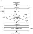
- FIG. 18 is a flowchart showing a manufacturing process of the rotary electric machine 100.
- FIG. 19 is a flowchart showing a manufacturing process of the coil 7.
- FIG. 20 is a developed view of the stator 10 in the coil forming process. It is a rear view which shows the state which the stator 10 was rotated (deformed) in a straight line, and is the figure which looked at the stator 10 from the outer peripheral side.
- FIG. 21 is a diagram showing the movement of the winding nozzle of the winding machine.
- stator core 11A is formed (ST1: stator core manufacturing process).
- the slot side covering portion 51d of the first winding frame 51 from one end side in the axial direction Y. Is fitted and mounted, and the slot side covering portion 54d of the fourth winding frame 54 is fitted and mounted from the other end side.
- the second core portion 62, the fifth core portion 65, and the eighth core portion 68 have a second winding frame 52 and a fourth winding frame 54, and a third core portion 63, a sixth core portion 66, and a ninth core portion 66.
- the third winding frame 53 and the fourth winding frame 54 are mounted on the core portion 69 (ST2: winding frame mounting step). In this way, three types of winding frames are attached to one end side of the nine core portions 60, and the same fourth winding frame 54 is attached to the other end side.
- the coil forming step (ST3) for forming the coil 7 will be described with reference to FIGS. 19, 20, 21, 11, 15, 15, and 17.
- the first coil wire 71 is introduced from the outer side X1 to the inner side X2 in the radial direction X by using the introduction groove portion 51in of the first core portion 61.
- the second coil wire 72 and the third coil wire 73 also use the introduction groove portions 52in and 53in of the second core portion 62 and the third core portion 63, respectively, from the outer side X1 in the radial direction X. It is introduced into the inner side X2 (FIG. 19, ST31: introduction step).
- the first core portion 61 using the three first winding nozzles N1, the second winding nozzle N2, and the third winding nozzle N3 of the winding machine whose details are not shown.
- the first coil wire 71, the second coil wire 72, and the third coil wire 73 are simultaneously wound around the tooth portions 11b of the second core portion 62 and the third core portion 63 as shown by arrows N11, N21, and N31. (FIG. 19, ST32: winding process).
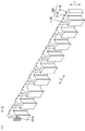
- FIG. 22 shows the movements of the first winding nozzle N1, the second winding nozzle N2, and the third winding nozzle N3 after the coil 7 of the first core portion 61, the second core portion 62, and the third core portion 63 is formed. It is a figure which shows.
- the first coil wire 71, the second coil wire 72, and the third coil is held at the lead-out groove portions 51out, 52out, and 53out of the first core portion 61, the second core portion 62, and the third core portion 63 so as to prevent loosening, and is held from the inner X2 to the outer X1 in the radial direction X. (See FIG. 20).
- the first winding nozzle N1, the second winding nozzle N2, and the third winding nozzle N3 are respectively placed in the direction of arrow E by the first coil. While feeding out the wire 71, the second coil wire 72, and the third coil wire 73, the first winding nozzle N1 reaches the position of the fourth core portion 64, and the second winding nozzle N2 moves to the position of the fifth core portion 65. Up to, the third winding nozzle N3 is moved to the position of the sixth core portion 66 by 3 teeth (FIG. 19, ST34: nozzle moving step).
- the lower end portion of the side surface on the crossover direction side is the first crossover wire 70J1 rather than the upper end portion.
- the first core portion 61 is held by the first groove portion M1 provided on the left side in the circumferential direction of the lead-out groove portion 51out in FIGS.
- the fourth core portion 64 which is routed and further connected in the circumferential direction Z, is held by the first groove portion M1 provided on the right side in the circumferential direction of the introduction groove portion 51in in FIGS. 11 and 20, and is held from the introduction groove portion 51in to the fourth core. It is introduced from the outer side X1 to the inner side X2 in the radial direction X of the portion 64.
- the lower end portion of the side surface on the crossover direction side is the second crossover wire 70J2 rather than the upper end portion.
- a third core portion 63 connected in the circumferential direction Z along the upper surface of the third guide G3 of the second core portion 62 shown in FIG. 15 from the bottom of the lead-out groove portion 52out inclined so as to be located on the crossover direction side.
- On the upper surface of the third guide G3 of the fifth core portion 65 which is held by the second groove portion M2 of the above and further held by the second groove portion M2 of the fourth core portion 64 connected in the circumferential direction Z, and further connected to the circumferential direction Z.
- it is introduced from the introduction groove portion 52in from the outer side X1 to the inner side X2 in the radial direction X of the fifth core portion 65.
- the lower end portion of the side surface on the crossover direction side is the third crossover wire 70J3 rather than the upper end portion.
- a fourth core portion connected in the circumferential direction Z along the upper surface of the fourth guide G4 of the third core portion 63 shown in FIG. 17 from the bottom of the lead-out groove portion 53out inclined so as to be located on the crossover direction side of the above.
- the upper surface of the fourth guide G4 of the sixth core portion 66 held by the third groove portion M3 of 64 and further connected to the third groove portion M3 of the fifth core portion 65 connected to the circumferential direction Z, and further connected to the circumferential direction Z. From the introduction groove portion 53in, the sixth core portion 66 is introduced from the outer side X1 to the inner side X2 in the radial direction X.
- the fourth core portion 64 and the fifth core are used by using the first winding nozzle N1, the second winding nozzle N2, and the third winding nozzle N3.
- the first coil wire 71, the second coil wire 72, and the third coil wire 73 are simultaneously wound around the tooth portions 11b of the portions 65 and the sixth core portion 66 as shown by arrows N11, N21, and N31.
- the first coil wire 71, the second coil wire 72, and the third coil are formed.
- the wire 73 is held at each of the lead-out groove portions 51out of the fourth core portion 64, the fifth core portion 65, and the sixth core portion 66 so as to prevent loosening, and is led out from the inner side X2 in the radial direction X to the outer side X1 ( (See FIG. 20).
- the first winding nozzle N1, the second winding nozzle N2, and the third winding nozzle N3 are moved in the direction of arrow E, respectively, with the first coil wire 71 and the second coil. While feeding out the wire 72 and the third coil wire 73, the first winding nozzle N1 reaches the position of the seventh core portion 67, and the second winding nozzle N2 reaches the position of the eighth core portion 68. The nozzle N3 is moved to the position of the ninth core portion 69.
- the lower end portion of the side surface on the crossover direction side is the fourth crossover wire 70J4 rather than the upper end portion.
- the fourth core portion 64 is held by the first groove portion M1 provided on the left side in the circumferential direction of the lead-out groove portion 51out in FIGS. Further, it is held by the first groove portion M1 of the fifth core portion 65 connected in the circumferential direction Z, and further along the upper surface of the second guide G2 and the lower surface of the first guide G1 of the sixth core portion 66 connected in the circumferential direction Z.
- the seventh core portion 67 which is routed and further connected in the circumferential direction Z is held by the first groove portion M1 provided on the right side in the circumferential direction of the introduction groove portion 51in in FIGS. 11 and 20, and is held from the introduction groove portion 51in to the seventh core. It is introduced from the outer side X1 to the inner side X2 in the radial direction X of the portion 67.
- the lower end portion of the side surface on the crossover direction side is the fifth crossover wire 70J5 rather than the upper end portion.
- the sixth core portion 66 connected in the circumferential direction Z along the upper surface of the third guide G3 of the fifth core portion 65 shown in FIG. 15 from the bottom of the lead-out groove portion 52out inclined so as to be located on the crossover direction side.
- it is introduced from the introduction groove portion 52in from the outer side X1 to the inner side X2 in the radial direction X of the eighth core portion 68.
- the lower end portion of the side surface on the crossing direction side is the sixth crossing wire 70J6 rather than the upper end portion.
- a seventh core portion connected in the circumferential direction Z along the upper surface of the fourth guide G4 of the sixth core portion 66 shown in FIG. 17 from the bottom of the lead-out groove portion 53out inclined so as to be located on the crossing direction side of the above.
- the upper surface of the fourth guide G4 of the ninth core portion 69 held by the third groove portion M3 of 67 and further connected to the third groove portion M3 of the eighth core portion 68 connected to the circumferential direction Z and further connected to the circumferential direction Z. From the introduction groove portion 53in, the ninth core portion 69 is introduced from the outer side X1 to the inner side X2 in the radial direction X.
- the seventh core portion 67 and the eighth core are used by using the first winding nozzle N1, the second winding nozzle N2, and the third winding nozzle N3.
- the first coil wire 71, the second coil wire 72, and the third coil wire 73 are simultaneously wound around the tooth portions 11b of the portions 68 and the ninth core portion 69 as shown by arrows N11, N21, and N31.
- the first coil wire 71, the second coil wire 72, and the third coil wire 73 are formed.
- the first volume ending line 712, the second volume ending line 722, and the third volume ending line 732 are formed.
- the final line 712 of the first volume, the final line 722 of the second volume, and the final line 732 of the third volume are crimped together to form the neutral point 700 of the star connection (see FIG. 3).
- a connection process such as caulking, brazing, or soldering with terminals may be used (FIG. 19, ST33-YES, ST35: connection, wiring process).
- the lower portion of the lead-out groove portion 51out of the first winding frame 51 is flush-topically connected to the upper surface of the second guide G2, and the lower portion of the lead-out groove portion 52out of the second winding frame 52 faces the upper surface of the third guide G3.
- the lower part of the lead-out groove portion 53out of the third winding frame 53 is connected to the upper surface of the fourth guide G4 flush with each other, and further, the lead-out groove portions 51out, 52out, 53out on the crossover direction side of the crossover 70J. Since the lower end of each side surface is inclined so as to be located on the crossover direction side of the crossover 70J from the upper end, each crossover 70J is actually led out from the groove portion 51out by simply moving the nozzle. At the same time as being fixed to the lower part of 53out, the crossover lines 70J constituting each phase are held in the first groove portions M1 to the third groove portions M3 at different heights in the axial direction.
- the first coil wire 71 formed in this way is a continuous wire without being cut in the middle, and is the first winding start wire 711, the coil 7 of the first core portion 61, and the first crossover wire. It is 70J1, the coil 7 of the fourth core portion 64, the fourth crossover 70J4, the coil 7 of the seventh core portion 67, and the end line 712 of the first volume.
- the second coil wire 72 is a continuous wire without being cut in the middle, and is the second winding start wire 721, the coil 7 of the second core portion 62, the second crossover wire 70J2, and the coil 7 of the fifth core portion 65.
- the third coil wire 73 is a continuous wire without being cut in the middle, and is the third winding start wire 731, the coil 7 of the third core portion 63, the third crossover wire 70J3, and the coil 7 of the sixth core portion 66. , The sixth crossover 70J6, the coil 7 of the ninth core portion 69, and the third volume final line 732.
- the process of using the first volume start line 711, the second volume start line 721, and the third volume start line 731 as the power supply line is performed.
- the three first winding start wires 711, the second winding start wire 721, and the third winding start wire 731 need to be arranged inside X2 in the radial direction X of the stator 10 when the stator 10 is made into an annular shape.
- the first winding start wire 711, the second winding start wire 721, and the third winding start wire 731 are in the radial direction of the stator 10. It is on the outside X1 side of X.
- the second groove portion M2 of the first core portion 61, the third groove portion M3, and the third groove portion M3 of the second core portion 62 are not used for holding the crossover 70J.
- the first volume start line 711, the second volume start line 721, and the third volume start line 731 are folded back as shown by the broken line in FIG. It is arranged inside X2 in the radial direction X of the stator 10 through the notch K which is passed through M2 and the third groove portion M3 and further cut out continuously in the circumferential direction Z of the introduction groove portion 51in of the first core portion 61.
- the first power supply line 713, the second power supply line 723, and the third power supply line 733 are lined inside X2 in the radial direction X by covering them with an insulating tube to maintain insulation (FIG. 19, ST35: connection, wiring process). ..
- each core portion 60 is rotated in an annular shape to be deformed, and the ends of the stator cores 11A are fixed to each other by welding or the like to form the stator 10 (FIG. 18, ST4: stator forming step).
- the outer peripheral surface of the stator 10 is fixed to the inner peripheral surface of the frame 101 (FIG. 18, ST5: stator fixing step).
- the rotor 20 is rotatably supported on the bracket 103 by a bearing (not shown), and the rotor 20 is arranged to face the stator 10 with a gap (FIG. 18, ST6: rotor arrangement step).
- the rotary electric machine 100 is formed by these steps.
- a method of linearly rotating a plurality of yoke portions 11a of the stator core 11A and winding the coil wire 70 around the teeth portion 11b to form the coil 7 has been shown, but the present invention is not limited to this. ..
- a method for forming a coil is performed by rotating a plurality of yoke portions 11a of the stator core 11A in a direction that projects in the radial direction X of the teeth portion in a reverse warp shape, which is opposite to the product state, by using a connecting portion. explain.
- FIG. 23 is a conceptual diagram showing another winding method.
- the stator 10 is the same, except that the winding machine is different.
- the winding machine 400 has a hexagonal chuck mechanism 40.
- the chuck mechanism 40 has chucks 41, 42, 43, 44, 45, 46.
- the first winding nozzle NB1, the second winding nozzle NB2, and the third winding nozzle NB3 for winding the coil wire 70 are installed at positions facing the chucks 41, 42, and 43 in FIG. 23.
- the first winding nozzle NB1, the second winding nozzle NB2, and the third winding nozzle NB3 are rotated around the rotating shaft RB1, the rotating shaft RB2, and the rotating shaft RB3, and the coil wire 70 is wound around each tooth portion 11b.
- FIG. 23 shows the axial direction Y inverted. That is, FIG. 23 is a diagram showing a state in which the fourth winding frame 54 of each core portion 60 is visible. Since the chuck mechanism 40 rotates in the direction of arrow R, the positions of the chucks 41 to 46 change.
- the first core portion 61, the second core portion 62, and the third core portion 63 are fixed to the chuck 41, the chuck 42, and the chuck 43, respectively. Then, the first winding nozzle NB1, the second winding nozzle NB2, and the third winding nozzle NB3 are rotated around the rotation shafts RB1, RB2, and RB3, and the coil wire 70 is wound around each tooth portion 11b to coil 7. To form.
- the first winding nozzle NB1, the second winding nozzle NB2, and the third winding nozzle NB3 are moved back and forth and up and down, and the chuck mechanism 40 is rotated. Then, the crossover line 70J is passed between the predetermined core portions 60 as in the case described above.
- the chuck mechanism 40 rotates at a pitch of 60 ° three times. That is, until the fourth core portion 64 shown in FIG. 23 comes to the position where the first core portion 61 was fixed in the first coil winding step (movement of three core portions 60), the pitch is 60 °. The rotation is repeated 3 times. At this time, all the other core portions 60 also move at the same time (core portion moving step instead of the nozzle moving step). Further, since the core portion 60 is sequentially discharged from the position of the chuck 46 shown in FIG. 23, the stator core 11A is not fixed to the chuck mechanism 40 at the position of the chuck 45 shown in FIG. 23.
- the coil wire 70 can be wound around the teeth portion 11b to form the coil 7 by ensuring a wide space between the teeth portions 11b adjacent to each other in the circumferential direction Z. That is, as shown in FIG. 23, the rotation axes of the first winding nozzle NB1, the second winding nozzle NB2, and the third winding nozzle NB3 can always be wound toward the teeth portion 11b side. Therefore, the coil wire 70 can be wound around the teeth portion 11b at high speed, and the cycle time for winding the coil wire 70 can be shortened.
- first winding frame 51 the first winding frame 51, the second winding frame 52, and the third winding frame 53, are used on one end side of each core portion 60, but the first winding frame Only 51 may be used.
- each core portion 60 may be integrally resin-molded with an insulating portion having a shape in which the first winding frame 51 and the fourth winding frame 54 are combined.
- the insulator is provided with a winding frame capable of forming the coil 7.
- a stator core in which a plurality of core portions having a yoke portion and a tooth portion formed so as to project radially inward from the central portion in the circumferential direction of the inner peripheral surface of the yoke portion are combined in an annular shape.
- a rotary electric machine provided with a coil formed by winding a coil wire around each of the plurality of teeth portions, and an insulating portion disposed between the core portion and the coil and insulating the stator core and the coil.
- the first winding frame as the insulating portion includes a first teeth end face covering portion that covers one end surface of the teeth portion in the axial direction of the portion around which the coil is wound, and a radial direction of the first teeth end face covering portion. It is connected to the outer end and is provided with a first outer collar that covers one end surface of the yoke portion in the axial direction and projects upward in the axial direction.
- the first outer collar is formed in the axial direction and has a first introduction groove portion for introducing the coil wire around which the coil is wound, and the coil wire formed in the axial direction and after winding the coil.
- the first lead-out groove portion that leads out to the outside in the radial direction of the stator core, Since it is provided with a plurality of guides extending in the circumferential direction and arranged in the axial direction to form a plurality of groove portions each holding a plurality of crossovers connecting the coils of the different teeth portions.
- Rotating electric machine that can prevent the interference of the crossover of the stator, make the number of turns of the coil of the teeth the same, make the direction of the winding start wire and the winding end wire common, and reduce electrical problems such as pulsation or vibration.
- Stator can be provided.
- the number of wiring members can be reduced, the manufacturing time can be shortened, and the productivity can be improved.
- the plurality of the groove portions are formed parallel to the circumferential direction, It extends in the circumferential direction and can prevent the interference of a plurality of crossovers arranged in the axial direction.
- first winding frame to be attached to the teeth portion and the yoke portion of the core portion constituting the U phase, and the first winding frame.
- the second winding frame is formed in the axial direction and has a second introduction groove portion for introducing a coil wire for winding the coil, and the coil wire formed in the axial direction after forming the coil.
- the second lead-out groove that leads out to the outside in the radial direction of It is provided with a plurality of guides extending in the circumferential direction and arranged in the axial direction, forming a plurality of grooves for holding a plurality of crossovers connecting the coils of the different teeth portions.
- the third winding frame is formed in the axial direction and has a third introduction groove portion for introducing a coil wire for winding the coil, and the coil wire formed in the axial direction after forming the coil.
- the third lead-out groove that leads out to the outside in the radial direction of It is provided with a plurality of guides extending in the circumferential direction and arranged in the axial direction, forming a plurality of grooves for holding a plurality of crossovers connecting the coils of the different teeth portions.
- the lower part of the first lead-out groove portion, the lower part of the second lead-out groove portion, and the lower part of the third lead-out groove portion are all different in axial height.
- the positions of the lower portions in the axial direction are higher in the order of the first lead-out groove portion, the second lead-out groove portion, and the third lead-out groove portion.
- the three-phase crossover can be smoothly guided, held and routed to grooves having different heights in the axial direction.
- the U-phase crossover is in the first groove
- the V-phase crossover is in the second groove
- the W-phase crossover is in the third. Since it is held in the groove, the crossovers of each phase do not interfere with each other.
- each of the first lead-out groove portion, the second lead-out groove portion, and the third lead-out groove portion on the crossover direction side of the crossover is closer to the crossover direction side than the upper end portion. Since it is tilted so that it is positioned, simply by moving the winding nozzle in the circumferential direction, the coil wires are guided to the lower part of the introduction groove along the side surface of the tilted introduction groove, and are flush with this. It can be guided and held from the upper surface of the predetermined guide connected to the predetermined groove to the predetermined groove portion.
- the lower positions of the first introduction groove, the second introduction groove, and the third introduction groove in the axial direction are lower than the position of the upper surface of the guide at the lowest position, the winding start line and the crossover It is possible to prevent interference with the wire.
- the yoke portion of the core portion is formed so that the yoke portion of each of the plurality of core portions can be linearly deformed.
- the yoke portion of the stator core is deformed linearly to form a linear shape.
- a method of manufacturing a stator of a rotary electric machine which has a nozzle moving step of moving three winding nozzles by three teeth at the same time to hold the three crossovers in the grooves having different heights.
- a coil wire can be wound around three consecutive teeth portions in the circumferential direction at the same time to form a coil, and the crossover wire of each phase can be continuously routed without interfering with each other. As a result, the number of wiring members can be reduced, and the product cost can be suppressed.
- the yoke portion is formed so as to be deformable in a reverse warp shape in which the directions of protrusion in the radial direction of the plurality of teeth portions are reversed.
- the yoke portion of the stator core is deformed in a reverse warp shape, A winding process in which three coil wires are formed into coils in three continuous teeth portions using three winding nozzles, and a winding process.
- a coil can be wound around the teeth at the same time to form a coil, and the crossovers of each phase can be subsequently drawn without interfering with each other.
- the number of wiring members can be reduced, and the product cost can be suppressed.
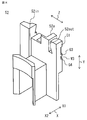
- FIG. 24 is a perspective view showing a state in which the first winding frame 251 and the second winding frame 252, the third winding frame 253, the fourth winding frame 254, and the film portion 230 are attached to each core portion 60.
- each core portion 60 is linearly deformed, and the first winding frame 251 on the upper side of the paper surface, the second winding frame 252, the third winding frame 253, the fourth winding frame 254 on the lower side of the paper surface, and the insulating portion are formed. A state in which the film portion 230 is mounted in each slot 14 is shown.
- FIG. 25 is an exploded perspective view of each member of FIG. 24.
- FIG. 26 is a perspective view showing the configuration of the film portion 230 shown in FIG. 24.
- FIG. 27A is a perspective view showing the configuration of the first winding frame 251 shown in FIG. 25.
- FIG. 27B is a perspective view of the first winding frame 251 shown in FIG. 27A as viewed from the opposite side in the axial direction Y.
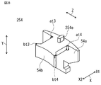
- FIG. 28 is a perspective view showing the configuration of the fourth winding frame 254.
- the first winding frame 251, the second winding frame 252, and the third winding frame 253 as insulating portions that insulate the plurality of core portions 60 and the coil 7.
- the configuration of the fourth winding frame 254 is different from each winding frame of the first embodiment.
- the insulating portion is composed of these four types of winding frames and a film portion 230 covering the wall surface of the slot.
- the first winding frame 251 and the second winding frame 252, the third winding frame 253, and the fourth winding frame 254 do not have the slot side covering portion that each winding frame had in the first embodiment. That is, as shown in FIG. 27A, the first winding frame 251 includes a tooth end face covering portion 251c, an outer collar 251a, and an inner collar 251b, and these are integrally formed.
- the tooth end face covering portion 251c covers one end surface of the tooth portion 11b in the axial direction Y of the portion around which the coil 7 is wound.
- the outer collar 251a is connected to the end of the outer side X1 of the tooth end surface covering portion 251c in the radial direction X, covers one end surface of the yoke portion 11a in the axial direction Y, and projects upward in the axial direction Y.
- the inner collar 251b is connected to the end of the inner X2 of the tooth end surface covering portion 251c in the radial direction X, covers the inner tip of the one end surface of the tooth portion 11b and one end surface of the shoe portion 11c, and is above the axial direction Y. Protrude.
- the first winding frame 251 includes claws bt1, bt2, and at1 for fixing the film portion 230, which will be described later.
- the claw portions bt1 and bt2 are provided on the outer side X1 of the radial direction X at both ends of the inner flange 251b in the circumferential direction Z.
- the remaining claw portion at1 is a side surface of the end portion of the tooth end surface covering portion 251c on the outer flange 251a side in the circumferential direction Z, and is provided on the side where the lead-out groove portion 251out exists.
- Each of the claw portions bt1, bt2, and at1 projects downward in the axial direction Y. It should be noted that the claw portion is not provided on the portion opposite to the side where the claw portion at1 is provided in the circumferential direction Z. Since the introduction groove portion 251 in for the coil wire 70 is provided on the outer side X1 side of the portion in the radial direction X, interference with the introduction wire is avoided.
- the fourth winding frame 254 is provided with four claw portions bt3, bt4, at3, and at4. Since the fourth winding frame 254 does not interfere with the introduction line, the claw portion at4 is provided in the portion corresponding to the portion omitted in the first winding frame 251.
- a convex portion 251e projecting downward in the axial direction Y is provided on the lower surface of the first winding frame 251.
- a convex portion 254e projecting downward in the axial direction Y is provided on the lower surface of the fourth winding frame 254.
- the convex portion 251e and the convex portion 254e are used to position the first winding frame 251 and the fourth winding frame 254 on both end faces of the core portion 60, respectively.
- the convex portion 251e is fitted into the second concave portion 11r provided on one end surface of the core portion 60, and the convex portion 254e is fitted into the second concave portion 11r provided on the other end surface of the core portion 60.
- the film portion 230 is formed of a thin-walled insulating film material, and it is conceivable to use, for example, a film material having a thickness of 0.125 mm. Then, the film material is formed by making a plurality of creases in a shape as shown in FIG. 26. Due to this crease, the film portion 230 is the first yoke inner peripheral surface covering portion that covers the yoke inner peripheral surface 112 which is one side surface of the axial direction Y of the inner side X2 of the yoke portion 11a of the first core portion 61 in the radial direction X2.
- the first side surface covering portion 232 covering the 231 and one side surface of the teeth portion 11b in the circumferential direction Z and the outer peripheral surface of the one shoe portion 11c, and the inner side X2 of the teeth portion 11b of the first core portion 61 in the radial direction X2.
- the other yoke inner peripheral surface 112 of 61 and the second yoke inner peripheral surface covering portion 231b that continuously covers one yoke inner peripheral surface 112 of the second core portion 62 are continuous, and these are repeated to form the ninth core portion. It is formed to cover up to 69.
- the film portion 230 includes claw portions bt1, bt2, at1 provided on each core portion 60 and the above-mentioned first winding frame 251, second winding frame 252, third winding frame 253, and fourth winding frame 254. , Since it is mounted by being sandwiched between bt1 to bt4, each core portion 60 and the coil 7 can be completely insulated. The continuous portion 233 and the inner peripheral surface covering portion of the second yoke are cut after winding the coil 7.
- stator and the winding method of the stator of the rotary electric machine are the same as those in the first embodiment.
- the method for manufacturing the stator of the rotary electric machine, the rotary electric machine, the stator of the rotary electric machine, and the manufacturing method of the rotary electric machine according to the second embodiment are combined in an annular shape.
- a rotary electric machine provided with a coil formed by winding a coil wire around each of the plurality of teeth portions, and an insulating portion disposed between the core portion and the coil and insulating the stator core and the coil. It is a stator of The first winding frame as the insulating portion includes a first teeth end face covering portion that covers one end surface of the teeth portion in the axial direction of the portion around which the coil is wound, and a radial direction of the first teeth end face covering portion. It is connected to the outer end and is provided with a first outer collar that covers one end surface of the yoke portion in the axial direction and projects upward in the axial direction.
- the first outer collar is formed in the axial direction and has a first introduction groove portion for introducing the coil wire around which the coil is wound, and the coil wire formed in the axial direction and after winding the coil.
- the first lead-out groove portion that leads out to the outside in the radial direction of the stator core, Since it is provided with a plurality of guides extending in the circumferential direction and arranged in the axial direction to form a plurality of groove portions each holding a plurality of crossovers connecting the coils of the different teeth portions.
- Rotating electric machine that can prevent the interference of the crossover of the stator, make the number of turns of the coil of the teeth the same, make the direction of the winding start wire and the winding end wire common, and reduce electrical problems such as pulsation or vibration.
- Stator can be provided.
- the number of wiring members can be reduced, the manufacturing time can be shortened, and the productivity can be improved.
- the plurality of the groove portions are formed parallel to the circumferential direction, It extends in the circumferential direction and can prevent the interference of a plurality of crossovers arranged in the axial direction.
- first winding frame to be attached to the teeth portion and the yoke portion of the core portion constituting the U phase, and the first winding frame.
- the second winding frame is formed in the axial direction and has a second introduction groove portion for introducing a coil wire for winding the coil, and the coil wire formed in the axial direction after forming the coil.
- the second lead-out groove that leads out to the outside in the radial direction of It is provided with a plurality of guides extending in the circumferential direction and arranged in the axial direction, forming a plurality of grooves for holding a plurality of crossovers connecting the coils of the different teeth portions.
- the third winding frame is formed in the axial direction and has a third introduction groove portion for introducing a coil wire for winding the coil, and the coil wire formed in the axial direction after forming the coil.
- the third lead-out groove that leads out to the outside in the radial direction of It is provided with a plurality of guides extending in the circumferential direction and arranged in the axial direction, forming a plurality of grooves for holding a plurality of crossovers connecting the coils of the different teeth portions.
- the lower part of the first lead-out groove portion, the lower part of the second lead-out groove portion, and the lower part of the third lead-out groove portion are all different in axial height.
- the positions of the lower portions in the axial direction are higher in the order of the first lead-out groove portion, the second lead-out groove portion, and the third lead-out groove portion.
- the three-phase crossover can be smoothly guided, held and routed to grooves having different heights in the axial direction.
- the U-phase crossover is in the first groove
- the V-phase crossover is in the second groove
- the W-phase crossover is in the third. Since it is held in the groove, the crossovers of each phase do not interfere with each other.
- each of the first lead-out groove portion, the second lead-out groove portion, and the third lead-out groove portion on the crossover direction side of the crossover is closer to the crossover direction side than the upper end portion. Since it is tilted so that it is positioned, simply by moving the winding nozzle in the circumferential direction, the coil wires are guided to the lower part of the introduction groove along the side surface of the tilted introduction groove, and are flush with this. It can be guided and held from the upper surface of the predetermined guide connected to the predetermined groove to the predetermined groove portion.
- the lower positions of the first introduction groove, the second introduction groove, and the third introduction groove in the axial direction are lower than the position of the upper surface of the guide at the lowest position, the winding start line and the crossover It is possible to prevent interference with the wire.
- the yoke portion of the core portion is formed so that the yoke portion of each of the plurality of core portions can be linearly deformed.
- the yoke portion of the stator core is deformed linearly to form a linear shape.
- a method of manufacturing a stator of a rotary electric machine which has a nozzle moving step of moving three winding nozzles by three teeth at the same time to hold the three crossovers in the grooves having different heights.
- a coil wire can be wound around three consecutive teeth portions in the circumferential direction at the same time to form a coil, and the crossover wire of each phase can be continuously routed without interfering with each other. As a result, the number of wiring members can be reduced, and the product cost can be suppressed.
- the yoke portion is formed so as to be deformable in a reverse warp shape in which the directions of protrusion in the radial direction of the plurality of teeth portions are reversed.
- the yoke portion of the stator core is deformed in a reverse warp shape, A winding process in which three coil wires are formed into coils in three continuous teeth portions using three winding nozzles, and a winding process.
- a coil can be wound around the teeth at the same time to form a coil, and the crossovers of each phase can be subsequently drawn without interfering with each other.
- the number of wiring members can be reduced, and the product cost can be suppressed.
- Embodiment 3 the method for manufacturing the stator of the rotary electric machine, the rotary electric machine, and the stator of the rotary electric machine according to the third embodiment and the method for manufacturing the rotary electric machine will be described with reference to the parts different from those of the first embodiment.
- the stator of the present embodiment is the same as the stator 10 of the first embodiment except that the configuration of the stator core 311A used for the stator is different.
- FIG. 29 is a perspective view of the stator core 311A.
- FIG. 30 is an enlarged plan view of a main part of the stator core 311A.
- the difference between the stator core 11A of the first embodiment and the stator core 311A of the third embodiment is that the adjacent core portions 60 constituting the stator core 11A of the first embodiment are located at the end of the yoke portion 11a in the circumferential direction Z. While they were connected by the rotatable connecting portion 111 formed, the adjacent core portions 360 constituting the stator core 311A of the third embodiment are formed at the end portion of the yoke portion 311a in the circumferential direction Z. It is connected by a bendable connecting portion 111B.
- the connecting portion 111 is formed by alternately laminating two types of core pieces 11k1 and 11k2 formed by punching a thin magnetic steel plate in the axial direction Y.
- a plurality of three 11k core plates of one type formed by punching a thin magnetic steel plate are laminated in the axial direction Y.
- the core plate 311k is formed so that the portions to be laminated to form the yoke portion 311a are arranged in a straight line, that is, the portions to be the teeth portions 311b are arranged in parallel, and the portions to be adjacent yoke portions are formed. Are not physically separated and are thinly connected. Therefore, a thin connecting portion 111B can be formed between the adjacent core portions 360 by simply stacking a plurality of one type of core plates 311k in the axial direction Y.
- the yoke portions 311a of each core portion 360 are maintained in a linearly aligned state.
- the stator of the third embodiment also includes the same insulating member as the insulating member used in the first embodiment or the second embodiment.
- the connecting portion 111B is plastically deformed and bent so that each yoke portion 311a is arranged in an annular shape.
- the positional relationship between the yoke portions 311a and the teeth portions 311b is the same as the positional relationship between the yoke portions 11a and the teeth portions 11b according to the first embodiment.
- the stator according to the present embodiment also has the same configuration as the stator according to the first embodiment except for the connecting portion of the stator core.
- a stator core in which a plurality of core portions having a yoke portion and a tooth portion formed so as to project radially inward from the central portion in the circumferential direction of the inner peripheral surface of the yoke portion are combined in an annular shape.
- a rotary electric machine provided with a coil formed by winding a coil wire around each of the plurality of teeth portions, and an insulating portion disposed between the core portion and the coil and insulating the stator core and the coil.
- the first winding frame as the insulating portion includes a first teeth end face covering portion that covers one end surface of the teeth portion in the axial direction of the portion around which the coil is wound, and a radial direction of the first teeth end face covering portion. It is connected to the outer end and is provided with a first outer collar that covers one end surface of the yoke portion in the axial direction and projects upward in the axial direction.
- the first outer collar is formed in the axial direction and has a first introduction groove portion for introducing the coil wire around which the coil is wound, and the coil wire formed in the axial direction and after winding the coil.
- the first lead-out groove portion that leads out to the outside in the radial direction of the stator core, Since it is provided with a plurality of guides extending in the circumferential direction and arranged in the axial direction to form a plurality of groove portions each holding a plurality of crossovers connecting the coils of the different teeth portions.
- Rotating electric machine that can prevent the interference of the crossover of the stator, make the number of turns of the coil of the teeth the same, make the direction of the winding start wire and the winding end wire common, and reduce electrical problems such as pulsation or vibration.
- Stator can be provided.
- the number of wiring members can be reduced, the manufacturing time can be shortened, and the productivity can be improved.
- the plurality of the groove portions are formed parallel to the circumferential direction, It extends in the circumferential direction and can prevent the interference of a plurality of crossovers arranged in the axial direction.
- first winding frame to be attached to the teeth portion and the yoke portion of the core portion constituting the U phase, and the first winding frame.
- the second winding frame is formed in the axial direction and has a second introduction groove portion for introducing a coil wire for winding the coil, and the coil wire formed in the axial direction after forming the coil.
- the second lead-out groove that leads out to the outside in the radial direction of It is provided with a plurality of guides extending in the circumferential direction and arranged in the axial direction, forming a plurality of grooves for holding a plurality of crossovers connecting the coils of the different teeth portions.
- the third winding frame is formed in the axial direction and has a third introduction groove portion for introducing a coil wire for winding the coil, and the coil wire formed in the axial direction after forming the coil.
- the third lead-out groove that leads out to the outside in the radial direction of It is provided with a plurality of guides extending in the circumferential direction and arranged in the axial direction, forming a plurality of grooves for holding a plurality of crossovers connecting the coils of the different teeth portions.
- the lower part of the first lead-out groove portion, the lower part of the second lead-out groove portion, and the lower part of the third lead-out groove portion are all different in axial height.
- the positions of the lower portions in the axial direction are higher in the order of the first lead-out groove portion, the second lead-out groove portion, and the third lead-out groove portion.
- the three-phase crossover can be smoothly guided, held and routed to grooves having different heights in the axial direction.
- the U-phase crossover is in the first groove
- the V-phase crossover is in the second groove
- the W-phase crossover is in the third. Since it is held in the groove, the crossovers of each phase do not interfere with each other.
- each of the first lead-out groove portion, the second lead-out groove portion, and the third lead-out groove portion on the crossover direction side of the crossover is closer to the crossover direction side than the upper end portion. Since it is tilted so that it is positioned, simply by moving the winding nozzle in the circumferential direction, the coil wires are guided to the lower part of the introduction groove along the side surface of the tilted introduction groove, and are flush with this. It can be guided and held from the upper surface of the predetermined guide connected to the predetermined groove to the predetermined groove portion.
- the lower positions of the first introduction groove, the second introduction groove, and the third introduction groove in the axial direction are lower than the position of the upper surface of the guide at the lowest position, the winding start line and the crossover It is possible to prevent interference with the wire.
- the yoke portion of the core portion since each of the yoke portions of the plurality of core portions is held in a straight line, the yoke portion is held linearly.
- a winding process in which three coil wires are formed into coils in three continuous teeth portions using three winding nozzles, and a winding process.
- a coil is formed by winding a coil wire around three consecutive teeth portions in the circumferential direction at the same time by using the method of manufacturing a stator of a rotary electric machine having a step of forming the yoke portion in an annular shape.
- the crossovers of each phase can be subsequently routed without interference.
- the number of wiring members can be reduced, and the product cost can be suppressed.
- each yoke portion is held linearly by the rigidity of the thin-walled connecting portion without using a jig, the fixing jig at the time of winding can be simplified.
- Embodiment 4 the method for manufacturing the stator of the rotary electric machine, the rotary electric machine, and the stator of the rotary electric machine according to the fourth embodiment and the method for manufacturing the rotary electric machine will be described with reference to the parts different from those of the first embodiment.
- the stator of the present embodiment is the same as the stator 10 of the first embodiment except that the configuration of the stator core used for the stator is different.
- FIG. 31 is a perspective view of the core portion 460.
- the core portion 460 includes a yoke portion 411a and a teeth portion 411b similar to the core portion 60 of the first embodiment.
- FIG. 32 is a perspective view showing a state of the stator 410 after winding.
- the difference between the stator core 11A of the first embodiment and the stator core 411A of the fourth embodiment is that the adjacent core portions 60 constituting the stator core 11A of the first embodiment are located at the end of the yoke portion 11a in the circumferential direction Z.
- the adjacent core portions 460 constituting the stator core 411A of the fourth embodiment do not have a connecting portion and are independently connected to each other. That is the point.
- the core portion 460 is also formed by laminating a plurality of core pieces 411k formed by punching a thin magnetic steel plate in the axial direction Y.
- the connecting portion 111 is formed by alternately laminating two types of core pieces 11k1 and 11k2 formed by punching a thin magnetic steel plate in the axial direction Y.
- the core portion 460 a plurality of one type of core pieces 411k formed by punching a thin magnetic steel plate are laminated in the axial direction Y.
- the stator 410 of the fourth embodiment is composed of nine independent core portions 460.
- the stator 410 of the fourth embodiment also includes the same insulating member as the insulating member used in the first embodiment or the second embodiment.
- all the core portions 460 are arranged and held on the core portion fixing jig 80 so that the yoke portions 411a are aligned in a straight line, and the winding is the same as that of the first embodiment. Is performed continuously. After that, the core portion fixing jig 80 is removed, the yoke portions 411a of the core portions 460 are combined so as to form an annular shape, and the adjacent core portions 460 are fixed to each other to form the stator 410.
- the fixing method is welding, shrink fitting, or the like.
- the stator according to the present embodiment has the same configuration as the stator according to the first embodiment except that the stator core does not have a connecting portion.
- a stator core in which a plurality of core portions having a yoke portion and a tooth portion formed so as to project radially inward from the central portion in the circumferential direction of the inner peripheral surface of the yoke portion are combined in an annular shape.
- a rotary electric machine provided with a coil formed by winding a coil wire around each of the plurality of teeth portions, and an insulating portion disposed between the core portion and the coil and insulating the stator core and the coil.
- the first winding frame as the insulating portion includes a first teeth end face covering portion that covers one end surface of the teeth portion in the axial direction of the portion around which the coil is wound, and a radial direction of the first teeth end face covering portion. It is connected to the outer end and is provided with a first outer collar that covers one end surface of the yoke portion in the axial direction and projects upward in the axial direction.
- the first outer collar is formed in the axial direction and has a first introduction groove portion for introducing the coil wire around which the coil is wound, and the coil wire formed in the axial direction and after winding the coil.
- the first lead-out groove portion that leads out to the outside in the radial direction of the stator core, Since it is provided with a plurality of guides extending in the circumferential direction and arranged in the axial direction to form a plurality of groove portions each holding a plurality of crossovers connecting the coils of the different teeth portions.
- Rotating electric machine that can prevent the interference of the crossover of the stator, make the number of turns of the coil of the teeth the same, make the direction of the winding start wire and the winding end wire common, and reduce electrical problems such as pulsation or vibration.
- Stator can be provided.
- the number of wiring members can be reduced, the manufacturing time can be shortened, and the productivity can be improved.
- the plurality of the groove portions are formed parallel to the circumferential direction, It extends in the circumferential direction and can prevent the interference of a plurality of crossovers arranged in the axial direction.
- first winding frame to be attached to the teeth portion and the yoke portion of the core portion constituting the U phase, and the first winding frame.
- the second winding frame is formed in the axial direction and has a second introduction groove portion for introducing a coil wire for winding the coil, and the coil wire formed in the axial direction after forming the coil.
- the second lead-out groove that leads out to the outside in the radial direction of It is provided with a plurality of guides extending in the circumferential direction and arranged in the axial direction, forming a plurality of grooves for holding a plurality of crossovers connecting the coils of the different teeth portions.
- the third winding frame is formed in the axial direction and has a third introduction groove portion for introducing a coil wire for winding the coil, and the coil wire formed in the axial direction after forming the coil.
- the third lead-out groove that leads out to the outside in the radial direction of It is provided with a plurality of guides extending in the circumferential direction and arranged in the axial direction, forming a plurality of grooves for holding a plurality of crossovers connecting the coils of the different teeth portions.
- the lower part of the first lead-out groove portion, the lower part of the second lead-out groove portion, and the lower part of the third lead-out groove portion are all different in axial height.
- the positions of the lower portions in the axial direction are higher in the order of the first lead-out groove portion, the second lead-out groove portion, and the third lead-out groove portion.
- the three-phase crossover can be smoothly guided, held and routed to grooves having different heights in the axial direction.
- the U-phase crossover is in the first groove
- the V-phase crossover is in the second groove
- the W-phase crossover is in the third. Since it is held in the groove, the crossovers of each phase do not interfere with each other.
- each of the first lead-out groove portion, the second lead-out groove portion, and the third lead-out groove portion on the crossover direction side of the crossover is closer to the crossover direction side than the upper end portion. Since it is tilted so that it is positioned, simply by moving the winding nozzle in the circumferential direction, the coil wires are guided to the lower part of the introduction groove along the side surface of the tilted introduction groove, and are flush with this. It can be guided and held from the upper surface of the predetermined guide connected to the predetermined groove to the predetermined groove portion.
- the lower positions of the first introduction groove, the second introduction groove, and the third introduction groove in the axial direction are lower than the position of the upper surface of the guide at the lowest position, the winding start line and the crossover It is possible to prevent interference with the wire.
- the yoke portion of the core portion can hold each of the yoke portions of the plurality of core portions in a straight line, the yoke portion can be held linearly.
- a method of manufacturing a stator of a rotary electric machine which has a nozzle moving step of moving three winding nozzles by three teeth at the same time to hold the three crossovers in the grooves having different heights.
- a coil wire can be wound around three consecutive teeth portions in the circumferential direction at the same time to form a coil, and the crossover wire of each phase can be continuously routed without interfering with each other.
- the core portion does not have a connecting portion, the mold of the core piece constituting the core portion can be miniaturized.
- the number of magnetic poles generated by the permanent magnets of the rotor is not limited to 6 poles, and may be the number according to the number of teeth portions of the stators 10 and 410.
- the number of magnetic poles is (((). 3 ⁇ 1) ⁇ N) may be used.
- UU'UVV'VWW'W a method of winding 3 teeth continuously to adjacent teeth
- the number of magnetic poles may be ((9 ⁇ 1) N). Further, in a method (UU'VV'WW'%) in which two teeth are continuously wound around adjacent teeth portions, when the number of teeth portions is 6.N (N is an integer of 1 or more), the magnetic poles The number of ((6 ⁇ 1) ⁇ N) may be.
Landscapes
- Engineering & Computer Science (AREA)
- Power Engineering (AREA)
- Manufacturing & Machinery (AREA)
- Manufacture Of Motors, Generators (AREA)
- Insulation, Fastening Of Motor, Generator Windings (AREA)
Abstract
第一外鍔(51a)は、軸方向に形成され、コイル(7)を巻回するコイル線を導入する第一導入溝部(51in)と、軸方向に形成され、コイル(7)を巻回した後のコイル線(70)を、ステータコア(11)の径方向外側に導出する第一導出溝部(51out)と、異なるティース部(11b)のコイル(7)同士を接続する複数の渡り線(70J)をそれぞれ保持する複数の溝部(M1~M3)を形成する、周方向に延び、かつ軸方向に並んだ複数のガイド(G1~G4)とを備える。
Description
本願は、回転電機のステータ、回転電機、回転電機のステータの製造方法および、回転電機の製造方法に関するものである。
従来、電動機または発電機等の回転電機に用いられるステータは、ステータコアと、ステータコアのティース間に形成されるスロットに収納して装着されるコイルとで構成される。コイルを形成するコイル線は、絶縁被覆されており、コイルは、ステータコアと電気的に絶縁される。しかし、回転電機のステータでは、コイルとステータコアとの十分な絶縁を確保するため、さらに、ステータコアとコイルとが接する部分に絶縁部を配設している。
従来のステータとして、連続する3ティースに対して同時にコイル線を巻回する技術が提案されている(例えば、特許文献1参照)。
一般に、回転電機のステータの製造においては、製品の品質を保つために、コイル間の渡り線の干渉の防止と、コイルの均一化が重要である。
特許文献1に記載のステータでは、3本の巻線ノズルを使用して6ティースのステータコアに3ティースずつ、それぞれ同時に巻線する。まず、3ティースのコイルを同時に形成し、それぞれ2個のティースを間に挟んで離間したティース間に渡り線を形成し、さらに連続して次の3ティースに同時にコイルを巻線している。
当該文献では、巻き始め線と渡り線とがクロスして干渉することを防ぐために、例えば、ステータの軸方向に巻き始め線を上側とした場合に、渡り線は下側の絶縁部材を介して施される。この連続した巻線を9ティースのステータで巻線する場合は、2回の渡り線の引き回し工程が必要となり、巻き始め線と巻き終わり線を上側に配置するためには、3回目に巻線する3ティースについては、コイルの巻数が半ターン多く、または少なく巻線され、回転電機の脈動または振動などの電気的な問題が発生するという課題があった。
本願は、上記のような課題を解決するための技術を開示するものであり、ステータの渡り線の干渉を防止するとともに、脈動または振動などの電気的な問題を低減できる回転電機のステータ、回転電機、回転電機のステータの製造方法および、回転電機の製造方法を提供することを目的とする。
本願に開示される回転電機のステータは、
ヨーク部と、ヨーク部の内周面の周方向の中央部から、径方向内側に突出して形成されたティース部とを有するコア部を複数個、環状に組み合わせたステータコアと、
複数の前記ティース部にそれぞれコイル線を巻回して形成されたコイルと、前記コア部と前記コイルとの間に配設され、前記ステータコアと前記コイルとを絶縁する絶縁部とを備えた回転電機のステータであって、
前記絶縁部としての第一巻枠は、前記ティース部の、前記コイルが巻装される部分の軸方向の一端面を覆う第一ティース端面被覆部と、前記第一ティース端面被覆部の径方向外側の端部に接続され、前記ヨーク部の軸方向の一端面を覆い軸方向上方に突出する第一外鍔を備え、
前記第一外鍔は、軸方向に形成され、前記コイルを巻回する前記コイル線を導入する第一導入溝部と、軸方向に形成され、前記コイルを巻回した後の前記コイル線を、前記ステータコアの径方向外側に導出する第一導出溝部と、
異なる前記ティース部のコイル同士を接続する複数の渡り線をそれぞれ保持する複数の溝部を形成する、周方向に延び、かつ軸方向に並んだ複数のガイドとを備えるものである。
また、本願に開示される回転電機は、
前記回転電機のステータと、
前記ステータの内側に空隙を介して対向配置されたロータとを備えるものである。
また、本願に開示される回転電機のステータの製造方法は、
複数の前記コア部の前記ヨーク部を直線状に変形し、
3本の前記コイル線を3個の巻線ノズルを用いて連続する3個の前記ティース部にそれぞれコイルを形成する巻線工程と、
3個の前記巻線ノズルを、同時に3ティース分移動させて3本の前記渡り線を高さの異なった前記溝部に保持させるノズル移動工程とを有するものである。
また、本願に開示される回転電機の製造方法は、前記回転電機のステータの製造方法によって製造されたステータの内側に、ロータを空隙を介して対向配置させるものである。
本願に開示される回転電機のステータ、回転電機、回転電機のステータの製造方法および、回転電機の製造方法によれば、ステータの渡り線の干渉を防止するとともに、脈動または振動などの電気的な問題を低減できる回転電機のステータ、回転電機、回転電機のステータの製造方法および、回転電機の製造方法を提供できる。
実施の形態1.
以下、実施の形態1による回転電機のステータ、回転電機、回転電機のステータの製造方法および、回転電機の製造方法を、図を用いて説明する。
図1は、回転電機100の軸方向に垂直な断面図である。
図2は、回転電機100のロータ20を、回転軸21の軸心を通る平面で切断した断面図である。
回転電機100は、円筒状のフレーム101と、フレーム101の軸方向両端の開口部を閉塞するブラケット103と、フレーム101の内側に嵌合されたステータ10と、2枚のブラケット103のそれぞれの中央に、図示しないベアリングを介して回転可能に支持され、外周面を、ステータ10の内周面に対向するように配設されたロータ20とを備える。ロータ20の外周面と、ステータ10の内周面との間には、空隙107が存在する。
また、回転軸21の外周に固定されたロータコア22には、永久磁石105がVの字状に埋め込まれているが、永久磁石は、直線状、或いは、他の形状に配置してもよい。また、永久磁石は埋め込まれてなくてもよく、ロータコア22の外周の表面に貼り付けてステータ10の内周面に対向するように配置してもよい。
以下の説明において、回転電機100のステータ10における各方向は、複数のコア部60のヨーク部11aを環状に配置して組み合わせた状態を基準として、それぞれ周方向Z、軸方向Y、径方向X、径方向Xの外側X1、径方向Xの内側X2として示す。よって、ステータ10について、ステータ10の各コア部60のそれぞれのヨーク部11aを直線状に回転して変形した場合、または、各ティース部11bの突出する方向を逆にする、すなわち、環状のステータ10の内側と外側を逆にする逆反り状に回転して変形した場合であっても、ステータ10のヨーク部11aが製品状態である環状に配置された状態の方向を基準として、各方向を、各図中に示して説明する。
また、特に断り無く「上」、「下」と言うときは、基準となる場所において、ステータ10の軸方向Yに垂直かつステータ10の中心を通る面側を「下」、その反対を「上」とする。また、高さの高低を比較する場合は、ステータ10の軸方向Yに垂直かつステータ10の中心を通る面からの距離によって比較するものとする。
ステータ10は、ヨーク部11aと、ヨーク部11aの内周面の周方向Zの中央部から、径方向Xの内側X2に突出して形成されたティース部11bとを有するコア部60を複数個、環状に組み合わせたステータコア11Aと、複数のティース部11bにそれぞれコイル線を巻回して形成されたコイル7と、各コア部60とコイル7との間に配設され、コア部60とコイル7とを絶縁する絶縁部とを備える。9個のコア部60が連結して組み合わされたものがステータコア11Aである。
図3は、本来環状である回転電機100のステータ10を、切り開いて直線状に変形した状態を示す背面図であり、ステータ10を外周側から見た図である。
以下の説明では、それぞれのコア部60に61~69の符号を付し、第一コア部61~第九コア部69として説明する。
図4は、図3に示すステータ10の斜視図であり、図3の裏側、すなわち、ステータ10の内側が見えている図である。
図5は、図3に示すステータ10のステータコア11Aを構成する2種のコア片群11k1、11k2の構成を示す斜視図である。
図6は、図5に示す2種のコア片群11k1、11k2を、それぞれ複数群、軸方向Yに交互に積層して形成されたステータコア11Aの構成を示す斜視図である。
図7は、コア部60の平面図である。
以下の説明では、それぞれのコア部60に61~69の符号を付し、第一コア部61~第九コア部69として説明する。
図4は、図3に示すステータ10の斜視図であり、図3の裏側、すなわち、ステータ10の内側が見えている図である。
図5は、図3に示すステータ10のステータコア11Aを構成する2種のコア片群11k1、11k2の構成を示す斜視図である。
図6は、図5に示す2種のコア片群11k1、11k2を、それぞれ複数群、軸方向Yに交互に積層して形成されたステータコア11Aの構成を示す斜視図である。
図7は、コア部60の平面図である。
図3、図4に示すように、ステータ10は、複数のコア部60からなるステータコア11Aと、コイル7と、ステータコア11Aとコイル7とを絶縁するために配置された絶縁部としての紙面上側の第一巻枠51、第二巻枠52、第三巻枠53、および紙面下側の第四巻枠54とを備える。図6に示すように、周方向Zに並んでいるコア部60を第一コイル線71の巻始め側から、第一コア部61、第二コア部62、第三コア部63、第四コア部64、第五コア部65、第六コア部66、第七コア部67、第八コア部68、第九コア部69とする。第一巻枠51は、第一コア部61、第四コア部64、第七コア部67に、すなわち、U相を構成するコア部60に使用される。第二巻枠52は、第二コア部62、第五コア部65、第八コア部68に、すなわち、V相を構成するコア部60に使用される。第三巻枠53は、第三コア部63、第六コア部66、第九コア部69に、すなわち、W相を構成するコア部60に使用されるが、違いについての詳細は、後述する。
ステータコア11Aは、薄肉の磁性鋼板を、図示しない金型内で打ち抜いて形成された図5に示す複数のコア片群11k1、11k2を、図6に示すように軸方向Yに、交互に複数群積層して形成される。これにより、ステータコア11Aは、第一コア部61~第九コア部69の各ヨーク部11aが、周方向Zの端部に設けた連結部111によって連結され形成される。図6では、ステータコア11Aは、9個の第一コア部61~第九コア部69が、連結部111にて直線状に連結されて構成されている。
この連結部111において、隣り合うコア部60のヨーク部11aは、自由に回転可能である。これにより、ステータコア11Aは、直線状、または、ティース部11bの径方向Xに突出する方向を逆にする逆反り状に回転可能となる。
ステータコイルは、U相、V相、W相の三相で構成され、周方向Zに連接するコア部60毎に異なる相が並ぶ、スター結線の結線構造である。そして、第一コア部61はU相(U1)、第二コア部62はV相(V1)、第三コア部63はW相(W1)、第四コア部64はU相(U2)、第五コア部65はV相(V2)、第六コア部66はW相(W2)、第七コア部67はU相(U3)、第八コア部68はV相(V3)、第九コア部69はW相(W3)のコイル7が巻回されている。
尚、当該順番の説明を必要としない場合には、第一コア部61~第九コア部69は、上述のようにコア部60と総称して説明する。また、各コア部60には、コイル7、および絶縁部としての上側の第一巻枠51、第二巻枠52、第三巻枠53、第四巻枠54がそれぞれ設置されている。但し、第一コア部61~第九コア部69は、それぞれのコア部60に、コイル7、絶縁部としての図4、紙面上側の第一巻枠51、第二巻枠52、第三巻枠53、同紙面下側の第四巻枠54が設置されている状態、または、設置されていない状態に関係無く、当該記載を採用する。
次に、図7に基づいてコア部60の各部の構成について説明する。ヨーク部11aの径方向Xの外側X1の軸方向Yに沿う面をヨーク外周面113とする。ヨーク外周面113には、周方向Zの中央部に、軸方向Yに延在する第一凹部114が形成されている。第一凹部114は、コイル7を形成する巻線機にステータコア11Aを取り付ける際の位置決めに用いられる。また、ティース部11bには、径方向Xの内側X2の先端から周方向Zにそれぞれ突出したシュー部11cを備える。ヨーク部11aの径方向Xの内側X2の、軸方向Yに沿う面をヨーク内周面112とする。
ティース部11bの周方向Zの両端の軸方向Yに沿う両面を、ティース部側面121、ティース部11bの径方向Xの内側X2の先端の、軸方向Yに沿う面をティース部内周面122とする。シュー部11cの径方向Xの外側X1の軸方向Yに沿う面を、シュー部外周面131とする。そして、ヨーク内周面112、ティース部側面121、および、シュー部外周面131によって囲まれた領域が、コイル線70が巻回されてコイル7が形成されるスロット14となる。
次に、絶縁部として図4、紙面上側の第一巻枠51、第二巻枠52、第三巻枠53及び同下側の第四巻枠54について説明する。
第一巻枠51は、第一コア部61、第四コア部64、第七コア部67に装着する巻枠である。第一巻枠51は、ティース部11bおよびヨーク部11aに装着する。
第二巻枠52は、第二コア部62、第五コア部65、第八コア部68に装着する巻枠である。第二巻枠52は、ティース部11bおよびヨーク部11aに装着する。
第三巻枠53は、第三コア部63、第六コア部66、第九コア部69に装着する巻枠である。第三巻枠53は、ティース部11bおよびヨーク部11aに装着する。
図8は、図3、4に示すステータ10に用いられる、第一巻枠51の構成を示す斜視図である。
第一巻枠51は、第一コア部61、第四コア部64、第七コア部67に装着する巻枠である。第一巻枠51は、ティース部11bおよびヨーク部11aに装着する。
第二巻枠52は、第二コア部62、第五コア部65、第八コア部68に装着する巻枠である。第二巻枠52は、ティース部11bおよびヨーク部11aに装着する。
第三巻枠53は、第三コア部63、第六コア部66、第九コア部69に装着する巻枠である。第三巻枠53は、ティース部11bおよびヨーク部11aに装着する。
図8は、図3、4に示すステータ10に用いられる、第一巻枠51の構成を示す斜視図である。
第一巻枠51は、ティース端面被覆部51c(第一ティース端面被覆部)と、外鍔51a(第一外鍔)と、内鍔51b(第一内鍔)と、スロット側面被覆部51d(第一スロット側面被覆部)とを備え、これらが一体として形成されている。
ティース端面被覆部51cは、ティース部11bの、コイル7が巻装される部分の軸方向Yの一端面を覆う。外鍔51aは、ティース端面被覆部51cの径方向Xの外側X1の端部に接続され、ヨーク部11aの軸方向Yの一端面を覆い軸方向Yの上方に突出する。
ティース端面被覆部51cは、ティース部11bの、コイル7が巻装される部分の軸方向Yの一端面を覆う。外鍔51aは、ティース端面被覆部51cの径方向Xの外側X1の端部に接続され、ヨーク部11aの軸方向Yの一端面を覆い軸方向Yの上方に突出する。
内鍔51bは、ティース端面被覆部51cの径方向Xの内側X2の端部に接続され、ティース部11bの軸方向Yの一端面の内側先端部およびシュー部11cの軸方向Yの一端面を覆い、軸方向Yの上方に突出する。
スロット側面被覆部51dは、ティース部11bのティース部側面121、ヨーク部11aのヨーク内周面112、およびシュー部11cのシュー部外周面131を覆う。スロット側面被覆部51dは、ティース端面被覆部51c、外鍔51a、内鍔51bから下方に突出している。実際には、スロット側面被覆部51dは、スロット14を構成する各面の軸方向Yの半分を覆っている。
図9は、図3、図4に示すステータ10に用いられる、第四巻枠54の構成を示す斜視図である。第四巻枠54は、図3に示すステータ10の紙面下側の絶縁部材である。
第四巻枠54は、ティース端面被覆部54c(第二ティース端面被覆部)と、外鍔54a(第二外鍔)と、内鍔54b(第二内鍔)と、スロット側面被覆部54d(第二スロット端面被覆部)とを備え、これらが一体として形成されている。
ティース端面被覆部54cは、ティース部11bの、コイル7が巻装される部分の軸方向Yの他端面を覆う。外鍔54aは、ティース端面被覆部54cの径方向Xの外側X1の端部に接続され、ヨーク部11aの軸方向Yの他端面を覆い軸方向Yの上方に突出する。
ティース端面被覆部54cは、ティース部11bの、コイル7が巻装される部分の軸方向Yの他端面を覆う。外鍔54aは、ティース端面被覆部54cの径方向Xの外側X1の端部に接続され、ヨーク部11aの軸方向Yの他端面を覆い軸方向Yの上方に突出する。
内鍔54bは、ティース端面被覆部54cの径方向Xの内側X2の端部に接続され、ティース部11bの軸方向Yの他端面の内側先端部およびシュー部11cの軸方向Yの他端面を覆い、軸方向Yの上方に突出する。
スロット側面被覆部54dは、ティース部11bのティース部側面121、ヨーク部11aのヨーク内周面112、およびシュー部11cのシュー部外周面131を覆う。スロット側面被覆部54dは、ティース端面被覆部54c、外鍔54a、内鍔54bから下方に突出している。実際には、スロット側面被覆部54dは、スロット14を構成する各面の軸方向Yの半分を覆っている。したがって、先述の第一巻枠51のスロット側面被覆部51dと、第四巻枠54のスロット側面被覆部54dとで、スロット14を構成する各側面の全面を覆うことができる。
第一巻枠51および第四巻枠54は、各コア部60に対して軸方向両側からスロット14の内周面に嵌合するように装着される。そして第一巻枠51および第四巻枠54は、コイル7と各コア部60とを電気的に絶縁する。第一巻枠51および第四巻枠54は、例えば、絶縁性樹脂の射出成型によって形成する。
尚、本実施の形態1においては、第一巻枠51のスロット側面被覆部51dと、第四巻枠54のスロット側面被覆部54dとの軸方向Yの長さをほぼ同一の長さに形成する例を示しているが、これに限られることはなく、それぞれの軸方向Yの長さは適宜変更可能であり、スロット14を構成する各側面を全て覆うことができればよい。
次に、コア部60の一つである、図3における一番右側の第一コア部61の構成を、図を用いて説明する。第一コア部61には、紙面上側に第一巻枠51が装着され、紙面下側に第四巻枠54が装着されている。
図10は、第一コア部61に第一巻枠51および第四巻枠54を装着した状態を示す斜視図である。
図11は、図10に示す第一巻枠51および第四巻枠54を装着した第一コア部61を径方向Xの外側X1から見た図、すなわち、第一コア部61を図10の矢印A方向に見た図である。
図12は、図10に示す第一巻枠51および第四巻枠54を装着した第一コア部61を径方向Xの内側X2から見た図、すなわち、第一コア部61を図10の矢印B方向に見た図である。
図13Aは、図10に示す第一巻枠51および第四巻枠54を装着した第一コア部61を周方向Zから見た図、すなわち、第一コア部61を図10の矢印C方向に見た図である。
図13Bは、図10に示す第一巻枠51および第四巻枠54を装着した第一コア部61を軸方向Yから見た図、すなわち、第一コア部61を図10の矢印D方向に見た図である。
図10、図11、図13Aに示すように、外鍔51aの径方向Xの外側X1の外周面には、軸方向Yに複数段に、周方向Z方向に延びる溝部Mが形成されている。ここでは溝部Mは、軸方向Yにおいてコア部60から離れた上側から、第一溝部M1、第二溝部M2、第三溝部M3の3段に形成されている。すなわち、第一溝部M1、第二溝部M2、第三溝部M3は、周方向Zに平行に、かつ軸方向Yに並んで、高さ違いに形成されている。第一溝部M1は、外鍔51aの外周面に、周方向Zに設けられた第一ガイドG1と第二ガイドG2との間に形成されている。同様に、第二溝部M2は、外鍔51aの外周面に、周方向Zに設けられた第二ガイドG2と第三ガイドG3との間に形成されている。第三溝部M3は、外鍔51aの外周面に、周方向Zに設けられた第三ガイドG3と第四ガイドG4との間に形成されている。したがって、第一ガイドG1~第四ガイドG4も、周方向Zに平行に、かつ軸方向Yに並んで、高さ違いに形成されていることになる。図11に示すように、実際には、第一ガイドG1は、後述する導出溝部51out(第一導出溝部)の周方向Zの両側と、後述する導入溝部51in(第一導入溝部)の周方向Zの一方の縁近傍のみに設けられているので、第一溝部M1が形成されているのは、導出溝部51outの周方向Zの両側と導入溝部51inの周方向Zの一方の縁近傍だけとなる。第二溝部M2および第三溝部M3は、断続的に、周方向Zに続いている。
第一溝部M1、第二溝部M2、第三溝部M3は、異なるティース部11bのコイル7同士を接続する複数の渡り線70Jを周方向に平行に保持するために用いる。この渡り線70Jは、コイル7同士の連続線である。外鍔51aに、軸方向Yに形成された導入溝部51inは、コイル7をティース部11bに巻回するために、ステータコア11Aの径方向Xの外側X1からコイル線70を径方向Xの内側X2に導入する入り口である。
外鍔51aに、軸方向Yに形成された導出溝部51outは、ティース部11bに巻回してコイル7を形成した後のコイル線70を、ステータコア11Aの径方向Xの内側X2から径方向Xの外側X1に導出する出口である。導出溝部51outは、渡り線70Jの渡り方向側の側面の下端部が、上端部よりも渡り線70Jの渡り方向側に位置するように傾斜している。
そして、図11に示すように、第一巻枠51の外鍔51aに形成される導出溝部51outは、下部が導出溝部51outの周方向Zの左側に設けられた第一溝部M1に繋がるように、導出溝部51outの下部の高さと、第一溝部M1の下面を構成する第二ガイドG2の上面の高さとが、同一の高さとなるように設定されている。すなわち、導出溝部51outの下部と、第二ガイドG2の上面とは、面一に繋がっている。
図14は、第二巻枠52の斜視図である。
図15は、第二巻枠52および第四巻枠54を装着した第二コア部62を径方向Xの外側X1から見た図である。
第二巻枠52の基本的な構成は、第一巻枠51と同じなので、異なる部分のみ説明する。
まず、第二巻枠52の外鍔52aには、第一巻枠51の外鍔51aに、周方向Zに断続的に設けられていた第二ガイドG2が、外鍔52aの周方向Zの中央部にだけ設けられており、周方向Zの両端部分には設けられていない。したがって、導出溝部52out(第二導出溝部)の周方向Zの両側には第二ガイドG2が存在せず、第一巻枠51における第一溝部M1と第二溝部M2とが一体となっている。導入溝部52in(第二導入溝部)の周方向Zの外側についても同様である。したがって、渡り線70Jを軸方向に固定できる溝部は、第三溝部M3と、周方向Zの中央部の第二溝部M2となる。
そして、図15に示すように、第二巻枠52の外鍔52aに形成される導出溝部52outは、第三ガイドG3の上面と同一の高さになるように設定されている。すなわち、導出溝部52outの下部と、第三ガイドG3の上面とは、面一に繋がっている。
図16は、第三巻枠53の斜視図である。
図17は、第三巻枠53および第四巻枠54を装着した第三コア部63を径方向Xの外側X1から見た図である。
第三巻枠53の基本的な構成は、第一巻枠51と同じなので、異なる部分のみ説明する。
まず、第三巻枠53の外鍔53aには、第一巻枠51の外鍔51aに、周方向Zに断続的に設けられていた第二ガイドG2、第三ガイドG3が、外鍔52aの周方向Zの中央部にだけ設けられており、周方向Zの両端部分には、これらのガイドは設けられていない。したがって、導出溝部53out(第三導出溝部)の周方向Zの両側には第二溝部M2、第三溝部M3が存在せず、第一巻枠51における第一溝部M1、第二溝部M2、第三溝部M3が一体となっている。導入溝部53in(第三導入溝部)の周方向Zの外側についても同様である。
そして、図17に示すように、第三巻枠53の外鍔53aに形成される導出溝部53outは、下部が第四ガイドG4の上面と同一の高さになるように設定されている。すなわち、導出溝部53outの下部と、第四ガイドG4の上面とは、面一に繋がっている。
次に、コイル線70について図3と図4を用いて説明する。コイル線70は、コイル7を形成するための線である。ここでは、第一コイル線71、第二コイル線72、第三コイル線73の三本のコイル線70を使用する。第一コイル線71、第二コイル線72、第三コイル線73において、コイル7の巻回を始める部分が、第一巻始線711、第二巻始線721、第三巻始線731である。
第一巻始線711、第二巻始線721、第三巻始線731を、ステータコア11Aの径方向Xの外側X1から内側X2に移動して、電源線として使用する場合は、それぞれの部分は、第一電源線713、第二電源線723、第三電源線733となる。
第一コイル線71、第二コイル線72、第三コイル線73において、コイル7の巻回が終わって引き出された部分が、第一巻終線712、第二巻終線722、第三巻終線732である。第一巻終線712、第二巻終線722、第三巻終線732は、結線され中性点700が形成される。尚、コイル線70の各部分の名称を用いて説明をする必要がない場合には、コイル線70として総称して説明する。
次に、渡り線70Jについて図3を用いて説明する。渡り線70Jは、コイル線70の一部として形成されている。渡り線70Jには、第一渡り線70J1、第二渡り線70J2、第三渡り線70J3、第四渡り線70J4、第五渡り線70J5、第六渡り線70J6がある。第一渡り線70J1は、第一コア部61のコイル7と、周方向Zに3個離れた第四コア部64のコイル7とを接続する。第二渡り線70J2は、第二コア部62のコイル7と、周方向Zに3個離れた第五コア部65のコイル7とを接続する。第三渡り線70J3は、第三コア部63のコイル7と、周方向Zに3個離れた第六コア部66のコイル7とを接続する。
第四渡り線70J4は、第四コア部64のコイル7と、周方向Zに3個離れた第七コア部67のコイル7とを接続する。第五渡り線70J5は、第五コア部65のコイル7と、周方向Zに3個離れた第八コア部68のコイル7とを接続する。第六渡り線70J6は、第六コア部66のコイル7と、周方向Zに3個離れた第九コア部69のコイル7とを接続する。
尚、第一渡り線70J1~第六渡り線70J6を区別して説明する必要がない場合には、これらを渡り線70Jとして総称して説明する。
次に、回転電機100の製造工程について説明する。
図18は、回転電機100の製造工程を示すフローチャートである。
図19は、コイル7の製造工程を示すフローチャートである。
図20は、コイル形成工程にあるステータ10の展開図である。ステータ10を直線状
に回転(変形)した状態を示す背面図であり、ステータ10を外周側から見た図である。
図21は、巻線機の巻線ノズルの動きを示す図である。
まず、磁性鋼板から、2種のコア片群11k1、11k2を交互に打ち抜きながら、それぞれ複数群、軸方向Yに積層するとともにヨーク部11aの連結部111によって、隣り合うコア部60を連結して、ステータコア11Aを形成する(ST1:ステータコア製造工程)。
図18は、回転電機100の製造工程を示すフローチャートである。
図19は、コイル7の製造工程を示すフローチャートである。
図20は、コイル形成工程にあるステータ10の展開図である。ステータ10を直線状
に回転(変形)した状態を示す背面図であり、ステータ10を外周側から見た図である。
図21は、巻線機の巻線ノズルの動きを示す図である。
まず、磁性鋼板から、2種のコア片群11k1、11k2を交互に打ち抜きながら、それぞれ複数群、軸方向Yに積層するとともにヨーク部11aの連結部111によって、隣り合うコア部60を連結して、ステータコア11Aを形成する(ST1:ステータコア製造工程)。
次に、第一コア部61、第四コア部64、第七コア部67の周方向Zの両側のスロット14内に、軸方向Yの一端側から第一巻枠51のスロット側面被覆部51dを嵌め込んで装着し、他端側から第四巻枠54のスロット側面被覆部54dを嵌め込んで装着する。同様に、第二コア部62、第五コア部65、第八コア部68には、第二巻枠52と第四巻枠54を、第三コア部63、第六コア部66、第九コア部69には、第三巻枠53と第四巻枠54を装着する(ST2:巻枠装着工程)。このように、9個のコア部60の一端側には、三種類の巻枠を装着し、他端側には、同じ第四巻枠54を装着する。
次に、コイル7を形成するコイル形成工程(ST3)について、図19、図20、図21、図11、図15、図17を用いて説明する。
まず、第一コイル線71を第一コア部61の導入溝部51inを用いて、径方向Xの外側X1から内側X2に導入する。この時、同時に、第二コイル線72、第三コイル線73も同様に、第二コア部62、第三コア部63のそれぞれの導入溝部52in、53inを用いて、径方向Xの外側X1から内側X2に導入する(図19、ST31:導入工程)。
まず、第一コイル線71を第一コア部61の導入溝部51inを用いて、径方向Xの外側X1から内側X2に導入する。この時、同時に、第二コイル線72、第三コイル線73も同様に、第二コア部62、第三コア部63のそれぞれの導入溝部52in、53inを用いて、径方向Xの外側X1から内側X2に導入する(図19、ST31:導入工程)。
そして、図21に示すように、詳細を図示しない巻線機の3本の第一巻線ノズルN1、第二巻線ノズルN2、第三巻線ノズルN3を用いて、第一コア部61、第二コア部62、第三コア部63のそれぞれのティース部11bに、第一コイル線71、第二コイル線72、第三コイル線73を同時に矢印N11、N21、N31のように巻回する(図19、ST32:巻線工程)。
図22は、第一コア部61、第二コア部62、第三コア部63のコイル7の形成後の第一巻線ノズルN1、第二巻線ノズルN2、第三巻線ノズルN3の動きを示す図である。
上述のように第一コア部61、第二コア部62、第三コア部63のそれぞれのティース部11bにコイル7を形成した後に、第一コイル線71、第二コイル線72、第三コイル線73を第一コア部61、第二コア部62、第三コア部63のそれぞれの導出溝部51out、52out、53outにて緩みを防止するように保持させ、径方向Xの内側X2から外側X1に導出する(図20参照)。そして、次の巻線工程を行うために(ステップST33-NO)、第一巻線ノズルN1、第二巻線ノズルN2、第三巻線ノズルN3を矢印Eの方向に、それぞれ、第一コイル線71、第二コイル線72、第三コイル線73を繰り出しながら、第一巻線ノズルN1は、第四コア部64の位置まで、第二巻線ノズルN2は、第五コア部65の位置まで、第三巻線ノズルN3は、第六コア部66の位置まで3ティース分移動させる(図19、ST34:ノズル移動工程)。
上述のように第一コア部61、第二コア部62、第三コア部63のそれぞれのティース部11bにコイル7を形成した後に、第一コイル線71、第二コイル線72、第三コイル線73を第一コア部61、第二コア部62、第三コア部63のそれぞれの導出溝部51out、52out、53outにて緩みを防止するように保持させ、径方向Xの内側X2から外側X1に導出する(図20参照)。そして、次の巻線工程を行うために(ステップST33-NO)、第一巻線ノズルN1、第二巻線ノズルN2、第三巻線ノズルN3を矢印Eの方向に、それぞれ、第一コイル線71、第二コイル線72、第三コイル線73を繰り出しながら、第一巻線ノズルN1は、第四コア部64の位置まで、第二巻線ノズルN2は、第五コア部65の位置まで、第三巻線ノズルN3は、第六コア部66の位置まで3ティース分移動させる(図19、ST34:ノズル移動工程)。
この際、第一コア部61のコイル7と第四コア部64のコイル7とを接続する第一渡り線70J1は、渡り方向側の側面の下端部が、上端部よりも第一渡り線70J1の渡り方向側に位置するように傾斜している導出溝部51outの底部から、第一コア部61の図11、20における導出溝部51outの周方向左側に設けられた第一溝部M1に保持され、さらに周方向Zに連接する第二コア部62の第一溝部M1に保持され、さらに周方向Zに連接する第三コア部63の第二ガイドG2の上面および第一ガイドG1の下面に沿って引き回され、さらに周方向Zに連接する第四コア部64の図11および図20における導入溝部51inの周方向右側に設けられた第一溝部M1に保持され、導入溝部51inから、第四コア部64の径方向Xの外側X1から内側X2に導入される。
また、第二コア部62のコイル7と第五コア部65のコイル7とを接続する第二渡り線70J2は、渡り方向側の側面の下端部が、上端部よりも第二渡り線70J2の渡り方向側に位置するように傾斜している導出溝部52outの底部から、図15に示す第二コア部62の第三ガイドG3の上面に沿って、周方向Zに連接する第三コア部63の第二溝部M2に保持され、さらに周方向Zに連接する第四コア部64の第二溝部M2に保持され、さらに周方向Zに連接する第五コア部65の第三ガイドG3の上面に沿って、導入溝部52inから、第五コア部65の径方向Xの外側X1から内側X2に導入される。
同様に、第三コア部63のコイル7と第六コア部66のコイル7とを接続する第三渡り線70J3は、渡り方向側の側面の下端部が、上端部よりも第三渡り線70J3の渡り方向側に位置するように傾斜している導出溝部53outの底部から、図17に示す第三コア部63の第四ガイドG4の上面に沿って、周方向Zに連接する第四コア部64の第三溝部M3に保持され、さらに周方向Zに連接する第五コア部65の第三溝部M3に保持され、さらに周方向Zに連接する第六コア部66の第四ガイドG4の上面に沿って、導入溝部53inから、第六コア部66の径方向Xの外側X1から内側X2に導入される。
そして、第一コア部61から第三コア部63と同様に、第一巻線ノズルN1、第二巻線ノズルN2、第三巻線ノズルN3を用いて、第四コア部64、第五コア部65、第六コア部66のそれぞれのティース部11bに第一コイル線71、第二コイル線72、第三コイル線73を同時に矢印N11、N21、N31のように巻回する。
このようにして第四コア部64、第五コア部65、第六コア部66のそれぞれのティース部11bにコイル7を形成した後に、第一コイル線71、第二コイル線72、第三コイル線73を第四コア部64、第五コア部65、第六コア部66のそれぞれの導出溝部51outにて緩みを防止するように保持させ、径方向Xの内側X2から外側X1に導出する(図20参照)。そして、次の巻線工程を行うために、第一巻線ノズルN1、第二巻線ノズルN2、第三巻線ノズルN3を矢印Eの方向に、それぞれ、第一コイル線71、第二コイル線72、第三コイル線73を繰り出しながら、第一巻線ノズルN1は、第七コア部67の位置まで、第二巻線ノズルN2は、第八コア部68の位置まで、第三巻線ノズルN3は、第九コア部69の位置まで移動させる。
この際、第四コア部64のコイル7と第七コア部67のコイル7とを接続する第四渡り線70J4は、渡り方向側の側面の下端部が、上端部よりも第四渡り線70J4の渡り方向側に位置するように傾斜している導出溝部51outの底部から、第四コア部64の図11、20における導出溝部51outの周方向左側に設けられた第一溝部M1に保持され、さらに周方向Zに連接する第五コア部65の第一溝部M1に保持され、さらに周方向Zに連接する第六コア部66の第二ガイドG2の上面および第一ガイドG1の下面に沿って引き回され、さらに周方向Zに連接する第七コア部67の図11および図20における導入溝部51inの周方向右側に設けられた第一溝部M1に保持され、導入溝部51inから、第七コア部67の径方向Xの外側X1から内側X2に導入される。
また、第五コア部65のコイル7と第八コア部68のコイル7とを接続する第五渡り線70J5は、渡り方向側の側面の下端部が、上端部よりも第五渡り線70J5の渡り方向側に位置するように傾斜している導出溝部52outの底部から、図15に示す第五コア部65の第三ガイドG3の上面に沿って、周方向Zに連接する第六コア部66の第二溝部M2に保持され、さらに周方向Zに連接する第七コア部67の第二溝部M2に保持され、さらに周方向Zに連接する第八コア部68の第三ガイドG3の上面に沿って、導入溝部52inから、第八コア部68の径方向Xの外側X1から内側X2に導入される。
同様に、第六コア部66のコイル7と第九コア部69のコイル7とを接続する第六渡り線70J6は、渡り方向側の側面の下端部が、上端部よりも第六渡り線70J6の渡り方向側に位置するように傾斜している導出溝部53outの底部から、図17に示す第六コア部66の第四ガイドG4の上面に沿って、周方向Zに連接する第七コア部67の第三溝部M3に保持され、さらに周方向Zに連接する第八コア部68の第三溝部M3に保持され、さらに周方向Zに連接する第九コア部69の第四ガイドG4の上面に沿って、導入溝部53inから、第九コア部69の径方向Xの外側X1から内側X2に導入される。
そして、第四コア部64から第六コア部66と同様に、第一巻線ノズルN1、第二巻線ノズルN2、第三巻線ノズルN3を用いて、第七コア部67、第八コア部68、第九コア部69のそれぞれのティース部11bに第一コイル線71、第二コイル線72、第三コイル線73を同時に矢印N11、N21、N31のように巻回する。
そして、第七コア部67、第八コア部68、第九コア部69のそれぞれのティース部11bにコイル7を形成した後に、第一コイル線71、第二コイル線72、第三コイル線73を切断して、第一巻終線712、第二巻終線722、第三巻終線732を形成する。そして、第一巻終線712、第二巻終線722、第三巻終線732をまとめてかしめ、スター結線の中性点700を形成する(図3参照)。まとめる方法としては、端子によるカシメ、ロウ付けまたは、はんだ付けなどの結線処理を用いてもよい(図19、ST33-YES、ST35:結線、配線工程)。
このように、第一巻枠51の導出溝部51outの下部は、第二ガイドG2の上面に面一に繋がり、第二巻枠52の導出溝部52outの下部は、第三ガイドG3の上面に面一に繋がり、第三巻枠53の導出溝部53outの下部は、第四ガイドG4の上面に面一に繋がっており、さらに、導出溝部51out、52out、53outの、渡り線70Jの渡り方向側のそれぞれの側面は、下端部が、上端部よりも渡り線70Jの渡り方向側に位置するように傾斜しているので、実際にはノズルを移動するだけで、各渡り線70Jが導出溝部51out~53outの下部に固定されると同時に、各相を構成する渡り線70Jが、軸方向に異なる高さにある第一溝部M1~第三溝部M3内に保持される。
図3に示すように、このように形成された第一コイル線71は、途中で切断せずに連続線として、第一巻始線711、第一コア部61のコイル7、第一渡り線70J1、第四コア部64のコイル7、第四渡り線70J4、第七コア部67のコイル7、そして、第一巻終線712となる。同様に、第二コイル線72は、途中で切断せずに連続線として、第二巻始線721、第二コア部62のコイル7、第二渡り線70J2、第五コア部65のコイル7、第五渡り線70J5、第八コア部68のコイル7、そして、第二巻終線722となる。同様に、第三コイル線73は、途中で切断せずに連続線として、第三巻始線731、第三コア部63のコイル7、第三渡り線70J3、第六コア部66のコイル7、第六渡り線70J6、第九コア部69のコイル7、そして、第三巻終線732となる。
次に、第一巻始線711、第二巻始線721、第三巻始線731を電源線として使用する処理を行う。この3本の第一巻始線711、第二巻始線721、第三巻始線731は、ステータ10を円環状にした際に、ステータ10の径方向Xの内側X2に配置する必要があるが、コイル7の巻回を終えた状態では、図3の実線に示すように、第一巻始線711、第二巻始線721、第三巻始線731は、ステータ10の径方向Xの外側X1側にある。
ところで、全てのコイル7を形成しても、第一コア部61の第二溝部M2、第三溝部M3、第二コア部62の第三溝部M3は渡り線70Jの保持に利用されていない。
そこで、図1の破線に示すように、第一巻始線711、第二巻始線721、第三巻始線731を図3破線で示すように折り返し、利用されていない上述の第二溝部M2、第三溝部M3に通し、さらに、第一コア部61の導入溝部51inの周方向Zに連続して切り欠いた切り欠きKを通してステータ10の径方向Xの内側X2に配置する。第一電源線713、第二電源線723、第三電源線733は、径方向Xの内側X2で、絶縁チューブを被せて絶縁を保ち配線処理される(図19、ST35:結線、配線工程)。
次に、各コア部60を円環状に回転して変形し、ステータコア11Aの端部同士を溶接等で固定してステータ10を形成する(図18、ST4:ステータ形成工程)。次に、フレーム101の内周面にステータ10の外周面を固定する(図18、ST5:ステータ固定工程)。
次に、図示しない軸受けによって、ブラケット103にロータ20を回転自在に支持し、ロータ20をステータ10に空隙を介して対向配置する(図18、ST6:ロータ配置工程)。これらの工程によって回転電機100が形成される。
次に、図示しない軸受けによって、ブラケット103にロータ20を回転自在に支持し、ロータ20をステータ10に空隙を介して対向配置する(図18、ST6:ロータ配置工程)。これらの工程によって回転電機100が形成される。
これまでの説明では、ステータコア11Aの複数のヨーク部11aを直線状に回転してコイル線70をティース部11bに巻回してコイル7を形成する方法を示したが、これに限られることはない。他の方法として、ステータコア11Aの複数のヨーク部11aに連結部を用いてティース部の径方向Xに突出する方向を、製品状態と逆にする逆反り状に回転させて行うコイルの形成方法について説明する。
図23は、他の巻線方法を示す概念図である。巻線機が異なるだけで製造するステータ10は同じである。巻線機400は、六角形のチャック機構40を有する。そして、チャック機構40は、チャック41、42、43、44、45、46を有する。
図23におけるチャック41、42、43と対向する位置に、コイル線70を巻回する第一巻線ノズルNB1、第二巻線ノズルNB2、第三巻線ノズルNB3が設置されている。第一巻線ノズルNB1、第二巻線ノズルNB2、第三巻線ノズルNB3は、回転軸RB1、回転軸RB2、回転軸RB3を中心に回転され、コイル線70を各ティース部11bに巻回する。但し、図23は、図3の場合と異なり、軸方向Yを反転して示している。すなわち、図23は、各コア部60の第四巻枠54が見えている状態を示した図である。なお、チャック機構40は、矢印R方向に回転するので、チャック41~46の位置は変化する。
まず、図23に示すように、チャック41、チャック42、チャック43に、それぞれ第一コア部61、第二コア部62、第三コア部63が固定される。そして、第一巻線ノズルNB1、第二巻線ノズルNB2、第三巻線ノズルNB3を回転軸RB1、RB2、RB3を中心に回転させ、コイル線70を各ティース部11bに巻回してコイル7を形成する。
そして、1回目のコイルの巻回工程が完了した後、第一巻線ノズルNB1、第二巻線ノズルNB2、第三巻線ノズルNB3を前後上下に移動させるとともに、チャック機構40を回転させることで、渡り線70Jをこれまで説明した場合と同様に、所定のコア部60間に渡らせる。
この際、チャック機構40は、60°ピッチで3回、回転する。すなわち、図23に示す第四コア部64が、1回目のコイル巻回工程において第一コア部61が固定されていた位置(コア部60の3個分移動)に来るまで、60°ピッチの回転を3回繰り返す。このとき、他の全てのコア部60も、同時に移動する(ノズル移動工程に代替するコア部移動工程)。また、図23に示すチャック46の位置からは、コア部60が順次排出されていくため、図23に示すチャック45の位置では、チャック機構40には、ステータコア11Aは、固定されていない。
この方法によれば、周方向Zに隣り合うティース部11b同士の間を広く確保してコイル線70をティース部11bに巻回してコイル7を形成できる。すなわち、図23に示すとおり、第一巻線ノズルNB1、第二巻線ノズルNB2、第三巻線ノズルNB3の回転軸を常にティース部11b側に向けて巻回できる。よって、ティース部11bに対して高速にコイル線70を巻回でき、コイル線70の巻回のサイクルタイムを短縮できる。
尚、本実施の形態1において示した回転電機のステータの製造方法は、以下の実施の形態においても同様に行うことができるため、その説明は適宜省略する。
また、本実施の形態1では、各コア部60の一端側に、第一巻枠51、第二巻枠52、第三巻枠53の3種の巻枠を使用したが、第一巻枠51だけを用いてもよい。
また、本実施の形態1では、絶縁部を複数の部材で構成する例を示したが、絶縁部は、各コア部60に一体成形してもよい。例えば、各コア部60に、第一巻枠51と、第四巻枠54とを合わせた形状の絶縁部を、一体として樹脂成形してもよい。
また、シュー部11cを設けないステータコアを用いても、絶縁物にコイル7を形成できる巻枠を備えていればよい。
上記のように構成された実施の形態1の回転電機のステータによれば、
ヨーク部と、ヨーク部の内周面の周方向の中央部から、径方向内側に突出して形成されたティース部とを有するコア部を複数個、環状に組み合わせたステータコアと、
複数の前記ティース部にそれぞれコイル線を巻回して形成されたコイルと、前記コア部と前記コイルとの間に配設され、前記ステータコアと前記コイルとを絶縁する絶縁部とを備えた回転電機のステータであって、
前記絶縁部としての第一巻枠は、前記ティース部の、前記コイルが巻装される部分の軸方向の一端面を覆う第一ティース端面被覆部と、前記第一ティース端面被覆部の径方向外側の端部に接続され、前記ヨーク部の軸方向の一端面を覆い軸方向上方に突出する第一外鍔を備え、
前記第一外鍔は、軸方向に形成され、前記コイルを巻回する前記コイル線を導入する第一導入溝部と、軸方向に形成され、前記コイルを巻回した後の前記コイル線を、前記ステータコアの径方向外側に導出する第一導出溝部と、
異なる前記ティース部のコイル同士を接続する複数の渡り線をそれぞれ保持する複数の溝部を形成する、周方向に延び、かつ軸方向に並んだ複数のガイドとを備えるので、
ステータの渡り線の干渉を防止するとともにティースのコイルの巻数を同じにし、巻き始め線と巻き終わり線の方向を共通にすることができ、脈動または振動などの電気的な問題を低減できる回転電機のステータを提供できる。また、結線部材を低減でき、且つ、製造時間を短縮して生産性を向上できる。
また、複数の前記溝部は、周方向に平行に形成されているので、
周方向に延び、軸方向に並んだ複数の渡り線の干渉を防止できる。
周方向に延び、軸方向に並んだ複数の渡り線の干渉を防止できる。
また、U相を構成する前記コア部の前記ティース部および前記ヨーク部に装着する前記第一巻枠と、
V相を構成する前記コア部の前記ティース部および前記ヨーク部に装着する前記絶縁部としての第二巻枠と、
W相を構成する前記コア部の前記ティース部および先記ヨーク部に装着する前記絶縁部としての第三巻枠とを備え、
前記第二巻枠は、軸方向に形成され、前記コイルを巻回するコイル線を導入する第二導入溝部と、軸方向に形成され、前記コイルを形成した後の前記コイル線を、前記ステータコアの径方向外側に導出する第二導出溝部と、
異なる前記ティース部の前記コイル同士を接続する複数の渡り線をそれぞれ保持する複数の溝部を形成する、周方向に延び、かつ軸方向に並んだ複数のガイドとを備え、
前記第三巻枠は、軸方向に形成され、前記コイルを巻回するコイル線を導入する第三導入溝部と、軸方向に形成され、前記コイルを形成した後の前記コイル線を、前記ステータコアの径方向外側に導出する第三導出溝部と、
異なる前記ティース部の前記コイル同士を接続する複数の渡り線をそれぞれ保持する複数の溝部を形成する、周方向に延び、かつ軸方向に並んだ複数のガイドとを備え、
前記第一導出溝部の下部と、前記第二導出溝部の下部と、前記第三導出溝部の下部の軸方向の高さは全て異なり、
前記第一導出溝部、前記第二導出溝部、前記第三導出溝部の順に、それぞれの下部の軸方向の位置が高く、
それぞれの下部は、いずれかの前記ガイドの上面と面一に繋がっているので、
3相の渡り線を、軸方向において高さのそれぞれ異なる溝部にスムーズに導き、保持して引き回すことができる。また、第一巻枠、第二巻枠、第三巻枠の全てについて、U相の渡り線は第一溝部に、V相の渡り線は第二溝部に、W相の渡り線は第三溝部に保持されるので、各相の渡り線が干渉しない。
また、前記第一導出溝部、前記第二導出溝部、前記第三導出溝部の、前記渡り線の渡り方向側のそれぞれの側面は、下端部が、上端部よりも前記渡り線の渡り方向側に位置するように傾斜しているので、巻線ノズルを周方向に移動させるだけで、傾斜している導入溝部の側面に沿って、それぞれコイル線を導入溝部の下部に案内し、これと面一に繋がる所定のガイドの上面からさらに所定の溝部に誘導して保持できる。
また、前記第一導入溝部、第二導入溝部、第三導入溝部のそれぞれの軸方向の下部の位置は、一番低い位置にある前記ガイドの上面の位置よりも低いので、巻き始め線と渡り線とが干渉することを防止できる。
また、前記コア部の前記ヨーク部は、複数の前記コア部のそれぞれの前記ヨーク部を直線状に変形可能に形成されているので、
前記ステータコアの前記ヨーク部を直線状に変形し、
3本の前記コイル線を3個の巻線ノズルを用いて連続する3個の前記ティース部にそれぞれコイルを形成する巻線工程と、
3個の前記巻線ノズルを、同時に3ティース分移動させて3本の前記渡り線を高さの異なった前記溝部に保持させるノズル移動工程とを有する回転電機のステータの製造方法を用いて、周方向に連続する3個のティース部に対して同時にコイル線を巻回してコイルを形成し、引き続いて干渉させずに各相の渡り線を引き回すことができる。これにより、結線部材を低減することができ、製品コストを抑制できる。
前記ステータコアの前記ヨーク部を直線状に変形し、
3本の前記コイル線を3個の巻線ノズルを用いて連続する3個の前記ティース部にそれぞれコイルを形成する巻線工程と、
3個の前記巻線ノズルを、同時に3ティース分移動させて3本の前記渡り線を高さの異なった前記溝部に保持させるノズル移動工程とを有する回転電機のステータの製造方法を用いて、周方向に連続する3個のティース部に対して同時にコイル線を巻回してコイルを形成し、引き続いて干渉させずに各相の渡り線を引き回すことができる。これにより、結線部材を低減することができ、製品コストを抑制できる。
また、前記ヨーク部は、複数の前記ティース部の径方向に突出する方向を逆にする逆反り状に変形可能に形成されているので、
前記ステータコアの前記ヨーク部を逆反り状に変形し、
3本の前記コイル線を3個の巻線ノズルを用いて連続する3個の前記ティース部にそれぞれコイルを形成する巻線工程と、
前記コア部を3個分移動させて3本の前記渡り線を高さの異なった前記溝部に保持させるノズル移動工程とを有する回転電機のステータの製造方法を用いて、周方向に連続する3個のティース部に対して同時にコイル線を巻回してコイルを形成し、引き続いて干渉させずに各相の渡り線を引き回すことができる。
これにより、結線部材を低減することができ、製品コストを抑制できる。
前記ステータコアの前記ヨーク部を逆反り状に変形し、
3本の前記コイル線を3個の巻線ノズルを用いて連続する3個の前記ティース部にそれぞれコイルを形成する巻線工程と、
前記コア部を3個分移動させて3本の前記渡り線を高さの異なった前記溝部に保持させるノズル移動工程とを有する回転電機のステータの製造方法を用いて、周方向に連続する3個のティース部に対して同時にコイル線を巻回してコイルを形成し、引き続いて干渉させずに各相の渡り線を引き回すことができる。
これにより、結線部材を低減することができ、製品コストを抑制できる。
実施の形態2.
以下、実施の形態2による回転電機のステータ、回転電機、回転電機のステータの製造方法および、回転電機の製造方法を、図を用いて、実施の形態1と異なる部分を中心に説明する。
図24は、各コア部60に、第一巻枠251、第二巻枠252、第三巻枠253、第四巻枠254および、フィルム部230を装着した状態を示す斜視図である。各コア部60のヨーク部11aを直線状に変形し、絶縁部としての紙面上側の第一巻枠251、第二巻枠252、第三巻枠253、紙面下側の第四巻枠254およびフィルム部230を各スロット14に装着した状態を示している。
以下、実施の形態2による回転電機のステータ、回転電機、回転電機のステータの製造方法および、回転電機の製造方法を、図を用いて、実施の形態1と異なる部分を中心に説明する。
図24は、各コア部60に、第一巻枠251、第二巻枠252、第三巻枠253、第四巻枠254および、フィルム部230を装着した状態を示す斜視図である。各コア部60のヨーク部11aを直線状に変形し、絶縁部としての紙面上側の第一巻枠251、第二巻枠252、第三巻枠253、紙面下側の第四巻枠254およびフィルム部230を各スロット14に装着した状態を示している。
図25は、図24の各部材を分解した斜視図である。
図26は、図24に示したフィルム部230の構成を示す斜視図である。
図27Aは、図25に示した第一巻枠251の構成を示す斜視図である。
図27Bは、図27Aに示した第一巻枠251を軸方向Yの反対側からみた斜視図である。
図28は、第四巻枠254の構成を示す斜視図である。
図26は、図24に示したフィルム部230の構成を示す斜視図である。
図27Aは、図25に示した第一巻枠251の構成を示す斜視図である。
図27Bは、図27Aに示した第一巻枠251を軸方向Yの反対側からみた斜視図である。
図28は、第四巻枠254の構成を示す斜視図である。
各図に示すように、実施の形態2のステータ10は、複数のコア部60と、コイル7とを絶縁する絶縁部としての第一巻枠251、第二巻枠252、第三巻枠253および第四巻枠254の構成が、実施の形態1の各巻枠と異なる。本実施の形態2において、複数のコア部60とコイル7とを絶縁するために絶縁部は、これら4種類の巻枠とスロットの壁面を覆うフィルム部230とによって構成される。
第一巻枠251、第二巻枠252、第三巻枠253および第四巻枠254は、実施の形態1における各巻枠が有していた、スロット側面被覆部を有していない。すなわち、図27Aに示すように、第一巻枠251は、ティース端面被覆部251cと、外鍔251aと、内鍔251bとを備え、これらが一体として形成されている。ティース端面被覆部251cは、ティース部11bの、コイル7が巻装される部分の軸方向Yの一端面を覆う。外鍔251aは、ティース端面被覆部251cの径方向Xの外側X1の端部に接続され、ヨーク部11aの軸方向Yの一端面を覆い軸方向Yの上方に突出する。
内鍔251bは、ティース端面被覆部251cの径方向Xの内側X2の端部に接続され、ティース部11bの一端面の内側先端部およびシュー部11cの一端面を覆い、軸方向Yの上方に突出する。
以下に説明する、巻枠の構成は、第一巻枠251、第二巻枠252、第三巻枠253とも共通であるため、第一巻枠251を用いて説明する。
第一巻枠251は、後述するフィルム部230を固定するための爪部bt1、bt2、at1を備える。3個の爪部の内、内鍔251bの周方向Zの両端部の径方向Xの外側X1には、爪部bt1、bt2を備える。残りの爪部at1は、ティース端面被覆部251cの外鍔251a側の端部の周方向Zの側面であって、導出溝部251outが存在する側に備えられている。それぞれの爪部bt1、bt2、at1は、軸方向Yの下方に向かって突出している。なお、爪部at1を設けている側と周方向Zに反対側の部分には、爪部は設けていない。当該部分の径方向Xの外側X1側には、コイル線70用の導入溝部251inを備えるために、導入線との干渉を避けている。
第一巻枠251は、後述するフィルム部230を固定するための爪部bt1、bt2、at1を備える。3個の爪部の内、内鍔251bの周方向Zの両端部の径方向Xの外側X1には、爪部bt1、bt2を備える。残りの爪部at1は、ティース端面被覆部251cの外鍔251a側の端部の周方向Zの側面であって、導出溝部251outが存在する側に備えられている。それぞれの爪部bt1、bt2、at1は、軸方向Yの下方に向かって突出している。なお、爪部at1を設けている側と周方向Zに反対側の部分には、爪部は設けていない。当該部分の径方向Xの外側X1側には、コイル線70用の導入溝部251inを備えるために、導入線との干渉を避けている。
図28に示すように、第四巻枠254には、4個の爪部bt3、bt4、at3、at4を備える。第四巻枠254については、導入線との干渉が起こらないので、第一巻枠251では省略した部分に相当する部分に、爪部at4を設けている。
また、図27Bに示すように、第一巻枠251の下面には、軸方向Yの下方に突出する凸部251eが設けられている。また、図28に示すように、第四巻枠254の下面には、軸方向Yの下方に突出する凸部254eが設けられている。凸部251e及び凸部254eは、それぞれの第一巻枠251、第四巻枠254を、コア部60の両端面に位置決めするために用いる。凸部251eは、コア部60の一端面に設けられた第二凹部11rに勘合され、凸部254eは、コア部60の他端面に設けられた第二凹部11rに勘合される。
フィルム部230は、薄肉の絶縁性を有するフィルム材によって形成され、例えば、厚みが0.125mmのフィルム材を用いることが考えられる。そして、当該フィルム材に、図26に示すような形状に複数の折り目をつけて形成される。この折り目によって、フィルム部230は、第一コア部61のヨーク部11aの径方向Xの内側X2の軸方向Yの一方の側面であるヨーク内周面112を覆う第一ヨーク内周面被覆部231と、ティース部11bの周方向Zの一方の側面および一方のシュー部11cの外周面を覆う、第一側面被覆部232と、第一コア部61のティース部11bの径方向Xの内側X2を回り込んで、他方のシュー部11cの外周面および他方のティース部11bの側面を覆う第二側面被覆部232bに続く連続部233と、上記の第二側面被覆部232bと、第一コア部61の他方のヨーク内周面112、第二コア部62の一方のヨーク内周面112を連続して覆う第二ヨーク内周面被覆部231bとが連続し、これらを繰り返して第九コア部69まで覆うように形成されている。
また、フィルム部230は、各コア部60と、上述の第一巻枠251、第二巻枠252、第三巻枠253、第四巻枠254に設けられた、爪部bt1、bt2、at1、bt1~bt4との間に挟み込んで装着されるので、各コア部60とコイル7とを完全に絶縁できる。なお、連続部233と第二ヨーク内周面被覆部とは、コイル7を巻回した後で切断される。
ステータの他の構成および回転電機のステータの巻線方法は、実施の形態1と同様である。
実施の形態2による回転電機のステータ、回転電機、回転電機のステータの製造方法および、回転電機の製造方法によれば、
ヨーク部と、ヨーク部の内周面の周方向の中央部から、径方向内側に突出して形成されたティース部とを有するコア部を複数個、環状に組み合わせたステータコアと、
複数の前記ティース部にそれぞれコイル線を巻回して形成されたコイルと、前記コア部と前記コイルとの間に配設され、前記ステータコアと前記コイルとを絶縁する絶縁部とを備えた回転電機のステータであって、
前記絶縁部としての第一巻枠は、前記ティース部の、前記コイルが巻装される部分の軸方向の一端面を覆う第一ティース端面被覆部と、前記第一ティース端面被覆部の径方向外側の端部に接続され、前記ヨーク部の軸方向の一端面を覆い軸方向上方に突出する第一外鍔を備え、
前記第一外鍔は、軸方向に形成され、前記コイルを巻回する前記コイル線を導入する第一導入溝部と、軸方向に形成され、前記コイルを巻回した後の前記コイル線を、前記ステータコアの径方向外側に導出する第一導出溝部と、
異なる前記ティース部のコイル同士を接続する複数の渡り線をそれぞれ保持する複数の溝部を形成する、周方向に延び、かつ軸方向に並んだ複数のガイドとを備えるので、
ステータの渡り線の干渉を防止するとともにティースのコイルの巻数を同じにし、巻き始め線と巻き終わり線の方向を共通にすることができ、脈動または振動などの電気的な問題を低減できる回転電機のステータを提供できる。また、結線部材を低減でき、且つ、製造時間を短縮して生産性を向上できる。
また、複数の前記溝部は、周方向に平行に形成されているので、
周方向に延び、軸方向に並んだ複数の渡り線の干渉を防止できる。
周方向に延び、軸方向に並んだ複数の渡り線の干渉を防止できる。
また、U相を構成する前記コア部の前記ティース部および前記ヨーク部に装着する前記第一巻枠と、
V相を構成する前記コア部の前記ティース部および前記ヨーク部に装着する前記絶縁部としての第二巻枠と、
W相を構成する前記コア部の前記ティース部および先記ヨーク部に装着する前記絶縁部としての第三巻枠とを備え、
前記第二巻枠は、軸方向に形成され、前記コイルを巻回するコイル線を導入する第二導入溝部と、軸方向に形成され、前記コイルを形成した後の前記コイル線を、前記ステータコアの径方向外側に導出する第二導出溝部と、
異なる前記ティース部の前記コイル同士を接続する複数の渡り線をそれぞれ保持する複数の溝部を形成する、周方向に延び、かつ軸方向に並んだ複数のガイドとを備え、
前記第三巻枠は、軸方向に形成され、前記コイルを巻回するコイル線を導入する第三導入溝部と、軸方向に形成され、前記コイルを形成した後の前記コイル線を、前記ステータコアの径方向外側に導出する第三導出溝部と、
異なる前記ティース部の前記コイル同士を接続する複数の渡り線をそれぞれ保持する複数の溝部を形成する、周方向に延び、かつ軸方向に並んだ複数のガイドとを備え、
前記第一導出溝部の下部と、前記第二導出溝部の下部と、前記第三導出溝部の下部の軸方向の高さは全て異なり、
前記第一導出溝部、前記第二導出溝部、前記第三導出溝部の順に、それぞれの下部の軸方向の位置が高く、
それぞれの下部は、いずれかの前記ガイドの上面と面一に繋がっているので、
3相の渡り線を、軸方向において高さのそれぞれ異なる溝部にスムーズに導き、保持して引き回すことができる。また、第一巻枠、第二巻枠、第三巻枠の全てについて、U相の渡り線は第一溝部に、V相の渡り線は第二溝部に、W相の渡り線は第三溝部に保持されるので、各相の渡り線が干渉しない。
V相を構成する前記コア部の前記ティース部および前記ヨーク部に装着する前記絶縁部としての第二巻枠と、
W相を構成する前記コア部の前記ティース部および先記ヨーク部に装着する前記絶縁部としての第三巻枠とを備え、
前記第二巻枠は、軸方向に形成され、前記コイルを巻回するコイル線を導入する第二導入溝部と、軸方向に形成され、前記コイルを形成した後の前記コイル線を、前記ステータコアの径方向外側に導出する第二導出溝部と、
異なる前記ティース部の前記コイル同士を接続する複数の渡り線をそれぞれ保持する複数の溝部を形成する、周方向に延び、かつ軸方向に並んだ複数のガイドとを備え、
前記第三巻枠は、軸方向に形成され、前記コイルを巻回するコイル線を導入する第三導入溝部と、軸方向に形成され、前記コイルを形成した後の前記コイル線を、前記ステータコアの径方向外側に導出する第三導出溝部と、
異なる前記ティース部の前記コイル同士を接続する複数の渡り線をそれぞれ保持する複数の溝部を形成する、周方向に延び、かつ軸方向に並んだ複数のガイドとを備え、
前記第一導出溝部の下部と、前記第二導出溝部の下部と、前記第三導出溝部の下部の軸方向の高さは全て異なり、
前記第一導出溝部、前記第二導出溝部、前記第三導出溝部の順に、それぞれの下部の軸方向の位置が高く、
それぞれの下部は、いずれかの前記ガイドの上面と面一に繋がっているので、
3相の渡り線を、軸方向において高さのそれぞれ異なる溝部にスムーズに導き、保持して引き回すことができる。また、第一巻枠、第二巻枠、第三巻枠の全てについて、U相の渡り線は第一溝部に、V相の渡り線は第二溝部に、W相の渡り線は第三溝部に保持されるので、各相の渡り線が干渉しない。
また、前記第一導出溝部、前記第二導出溝部、前記第三導出溝部の、前記渡り線の渡り方向側のそれぞれの側面は、下端部が、上端部よりも前記渡り線の渡り方向側に位置するように傾斜しているので、巻線ノズルを周方向に移動させるだけで、傾斜している導入溝部の側面に沿って、それぞれコイル線を導入溝部の下部に案内し、これと面一に繋がる所定のガイドの上面からさらに所定の溝部に誘導して保持できる。
また、前記第一導入溝部、第二導入溝部、第三導入溝部のそれぞれの軸方向の下部の位置は、一番低い位置にある前記ガイドの上面の位置よりも低いので、巻き始め線と渡り線とが干渉することを防止できる。
また、前記コア部の前記ヨーク部は、複数の前記コア部のそれぞれの前記ヨーク部を直線状に変形可能に形成されているので、
前記ステータコアの前記ヨーク部を直線状に変形し、
3本の前記コイル線を3個の巻線ノズルを用いて連続する3個の前記ティース部にそれぞれコイルを形成する巻線工程と、
3個の前記巻線ノズルを、同時に3ティース分移動させて3本の前記渡り線を高さの異なった前記溝部に保持させるノズル移動工程とを有する回転電機のステータの製造方法を用いて、周方向に連続する3個のティース部に対して同時にコイル線を巻回してコイルを形成し、引き続いて干渉させずに各相の渡り線を引き回すことができる。これにより、結線部材を低減することができ、製品コストを抑制できる。
前記ステータコアの前記ヨーク部を直線状に変形し、
3本の前記コイル線を3個の巻線ノズルを用いて連続する3個の前記ティース部にそれぞれコイルを形成する巻線工程と、
3個の前記巻線ノズルを、同時に3ティース分移動させて3本の前記渡り線を高さの異なった前記溝部に保持させるノズル移動工程とを有する回転電機のステータの製造方法を用いて、周方向に連続する3個のティース部に対して同時にコイル線を巻回してコイルを形成し、引き続いて干渉させずに各相の渡り線を引き回すことができる。これにより、結線部材を低減することができ、製品コストを抑制できる。
また、前記ヨーク部は、複数の前記ティース部の径方向に突出する方向を逆にする逆反り状に変形可能に形成されているので、
前記ステータコアの前記ヨーク部を逆反り状に変形し、
3本の前記コイル線を3個の巻線ノズルを用いて連続する3個の前記ティース部にそれぞれコイルを形成する巻線工程と、
前記コア部を3個分移動させて3本の前記渡り線を高さの異なった前記溝部に保持させるノズル移動工程とを有する回転電機のステータの製造方法を用いて、周方向に連続する3個のティース部に対して同時にコイル線を巻回してコイルを形成し、引き続いて干渉させずに各相の渡り線を引き回すことができる。
これにより、結線部材を低減することができ、製品コストを抑制できる。
前記ステータコアの前記ヨーク部を逆反り状に変形し、
3本の前記コイル線を3個の巻線ノズルを用いて連続する3個の前記ティース部にそれぞれコイルを形成する巻線工程と、
前記コア部を3個分移動させて3本の前記渡り線を高さの異なった前記溝部に保持させるノズル移動工程とを有する回転電機のステータの製造方法を用いて、周方向に連続する3個のティース部に対して同時にコイル線を巻回してコイルを形成し、引き続いて干渉させずに各相の渡り線を引き回すことができる。
これにより、結線部材を低減することができ、製品コストを抑制できる。
実施の形態3.
以下、実施の形態3による回転電機のステータ、回転電機、回転電機のステータの製造方法および、回転電機の製造方法を、図を用いて、実施の形態1と異なる部分を中心に説明する。
本実施の形態のステータは、ステータに用いられているステータコア311Aの構成が異なる以外、実施の形態1のステータ10と同様である。
以下、実施の形態3による回転電機のステータ、回転電機、回転電機のステータの製造方法および、回転電機の製造方法を、図を用いて、実施の形態1と異なる部分を中心に説明する。
本実施の形態のステータは、ステータに用いられているステータコア311Aの構成が異なる以外、実施の形態1のステータ10と同様である。
図29は、ステータコア311Aの斜視図である。
図30は、ステータコア311Aの要部拡大平面図である。
実施の形態1のステータコア11Aと本実施の形態3のステータコア311Aとの違いは、実施の形態1のステータコア11Aを構成する隣り合うコア部60同士が、ヨーク部11aの周方向Zの端部に形成された回転可能な連結部111によって連結されていたのに対して、本実施の形態3のステータコア311Aを構成する隣り合うコア部360同士が、ヨーク部311aの周方向Zの端部に形成された折り曲げ可能な連結部111Bによって連結されている。
図30は、ステータコア311Aの要部拡大平面図である。
実施の形態1のステータコア11Aと本実施の形態3のステータコア311Aとの違いは、実施の形態1のステータコア11Aを構成する隣り合うコア部60同士が、ヨーク部11aの周方向Zの端部に形成された回転可能な連結部111によって連結されていたのに対して、本実施の形態3のステータコア311Aを構成する隣り合うコア部360同士が、ヨーク部311aの周方向Zの端部に形成された折り曲げ可能な連結部111Bによって連結されている。
実施の形態1のステータコア11Aは、薄肉の磁性鋼板を打ち抜いて形成された2種類のコア片群11k1、11k2を交互に、軸方向Yに積層することによって、連結部111を形成していたが、本実施の形態3では、薄肉の磁性鋼板を打ち抜いて形成された1種類のコア板311kを複数枚、軸方向Yに積層している点である。
コア板311kは、積層されてヨーク部311aとなる部分が、直線状に並ぶように、すなわち、ティース部311bとなる部分が、平行に並ぶように形成されており、隣り合うヨーク部となる部分は、物理的に分離されず、薄肉連結されている。したがって、1種類のコア板311kを複数枚、軸方向Yに積層するだけで、隣り合うコア部360の間に薄肉の連結部111Bを形成できる。
コア板311kを複数枚、軸方向Yに積層した状態では、各コア部360のヨーク部311aが、直線状に並んだ状態が保持される。本実施の形態3のステータも、実施の形態1、もしくは実施の形態2で用いた絶縁部材と同じ絶縁部材を備えている。
各ティース部311bに巻線完了後に、連結部111Bを塑性変形させて、各ヨーク部311aが円環状に並ぶように折り曲げる。このとき、各ヨーク部311aおよび各ティース部311bの位置関係は、実施の形態1の各ヨーク部11aおよびティース部11bの位置関係と同じになる。
各ティース部311bに巻線完了後に、連結部111Bを塑性変形させて、各ヨーク部311aが円環状に並ぶように折り曲げる。このとき、各ヨーク部311aおよび各ティース部311bの位置関係は、実施の形態1の各ヨーク部11aおよびティース部11bの位置関係と同じになる。
本実施の形態によるステータも、ステータコアの連結部以外の構成は、実施の形態1のステータと同様の構成であり、
ヨーク部と、ヨーク部の内周面の周方向の中央部から、径方向内側に突出して形成されたティース部とを有するコア部を複数個、環状に組み合わせたステータコアと、
複数の前記ティース部にそれぞれコイル線を巻回して形成されたコイルと、前記コア部と前記コイルとの間に配設され、前記ステータコアと前記コイルとを絶縁する絶縁部とを備えた回転電機のステータであって、
前記絶縁部としての第一巻枠は、前記ティース部の、前記コイルが巻装される部分の軸方向の一端面を覆う第一ティース端面被覆部と、前記第一ティース端面被覆部の径方向外側の端部に接続され、前記ヨーク部の軸方向の一端面を覆い軸方向上方に突出する第一外鍔を備え、
前記第一外鍔は、軸方向に形成され、前記コイルを巻回する前記コイル線を導入する第一導入溝部と、軸方向に形成され、前記コイルを巻回した後の前記コイル線を、前記ステータコアの径方向外側に導出する第一導出溝部と、
異なる前記ティース部のコイル同士を接続する複数の渡り線をそれぞれ保持する複数の溝部を形成する、周方向に延び、かつ軸方向に並んだ複数のガイドとを備えるので、
ステータの渡り線の干渉を防止するとともにティースのコイルの巻数を同じにし、巻き始め線と巻き終わり線の方向を共通にすることができ、脈動または振動などの電気的な問題を低減できる回転電機のステータを提供できる。また、結線部材を低減でき、且つ、製造時間を短縮して生産性を向上できる。
また、複数の前記溝部は、周方向に平行に形成されているので、
周方向に延び、軸方向に並んだ複数の渡り線の干渉を防止できる。
周方向に延び、軸方向に並んだ複数の渡り線の干渉を防止できる。
また、U相を構成する前記コア部の前記ティース部および前記ヨーク部に装着する前記第一巻枠と、
V相を構成する前記コア部の前記ティース部および前記ヨーク部に装着する前記絶縁部としての第二巻枠と、
W相を構成する前記コア部の前記ティース部および先記ヨーク部に装着する前記絶縁部としての第三巻枠とを備え、
前記第二巻枠は、軸方向に形成され、前記コイルを巻回するコイル線を導入する第二導入溝部と、軸方向に形成され、前記コイルを形成した後の前記コイル線を、前記ステータコアの径方向外側に導出する第二導出溝部と、
異なる前記ティース部の前記コイル同士を接続する複数の渡り線をそれぞれ保持する複数の溝部を形成する、周方向に延び、かつ軸方向に並んだ複数のガイドとを備え、
前記第三巻枠は、軸方向に形成され、前記コイルを巻回するコイル線を導入する第三導入溝部と、軸方向に形成され、前記コイルを形成した後の前記コイル線を、前記ステータコアの径方向外側に導出する第三導出溝部と、
異なる前記ティース部の前記コイル同士を接続する複数の渡り線をそれぞれ保持する複数の溝部を形成する、周方向に延び、かつ軸方向に並んだ複数のガイドとを備え、
前記第一導出溝部の下部と、前記第二導出溝部の下部と、前記第三導出溝部の下部の軸方向の高さは全て異なり、
前記第一導出溝部、前記第二導出溝部、前記第三導出溝部の順に、それぞれの下部の軸方向の位置が高く、
それぞれの下部は、いずれかの前記ガイドの上面と面一に繋がっているので、
3相の渡り線を、軸方向において高さのそれぞれ異なる溝部にスムーズに導き、保持して引き回すことができる。また、第一巻枠、第二巻枠、第三巻枠の全てについて、U相の渡り線は第一溝部に、V相の渡り線は第二溝部に、W相の渡り線は第三溝部に保持されるので、各相の渡り線が干渉しない。
V相を構成する前記コア部の前記ティース部および前記ヨーク部に装着する前記絶縁部としての第二巻枠と、
W相を構成する前記コア部の前記ティース部および先記ヨーク部に装着する前記絶縁部としての第三巻枠とを備え、
前記第二巻枠は、軸方向に形成され、前記コイルを巻回するコイル線を導入する第二導入溝部と、軸方向に形成され、前記コイルを形成した後の前記コイル線を、前記ステータコアの径方向外側に導出する第二導出溝部と、
異なる前記ティース部の前記コイル同士を接続する複数の渡り線をそれぞれ保持する複数の溝部を形成する、周方向に延び、かつ軸方向に並んだ複数のガイドとを備え、
前記第三巻枠は、軸方向に形成され、前記コイルを巻回するコイル線を導入する第三導入溝部と、軸方向に形成され、前記コイルを形成した後の前記コイル線を、前記ステータコアの径方向外側に導出する第三導出溝部と、
異なる前記ティース部の前記コイル同士を接続する複数の渡り線をそれぞれ保持する複数の溝部を形成する、周方向に延び、かつ軸方向に並んだ複数のガイドとを備え、
前記第一導出溝部の下部と、前記第二導出溝部の下部と、前記第三導出溝部の下部の軸方向の高さは全て異なり、
前記第一導出溝部、前記第二導出溝部、前記第三導出溝部の順に、それぞれの下部の軸方向の位置が高く、
それぞれの下部は、いずれかの前記ガイドの上面と面一に繋がっているので、
3相の渡り線を、軸方向において高さのそれぞれ異なる溝部にスムーズに導き、保持して引き回すことができる。また、第一巻枠、第二巻枠、第三巻枠の全てについて、U相の渡り線は第一溝部に、V相の渡り線は第二溝部に、W相の渡り線は第三溝部に保持されるので、各相の渡り線が干渉しない。
また、前記第一導出溝部、前記第二導出溝部、前記第三導出溝部の、前記渡り線の渡り方向側のそれぞれの側面は、下端部が、上端部よりも前記渡り線の渡り方向側に位置するように傾斜しているので、巻線ノズルを周方向に移動させるだけで、傾斜している導入溝部の側面に沿って、それぞれコイル線を導入溝部の下部に案内し、これと面一に繋がる所定のガイドの上面からさらに所定の溝部に誘導して保持できる。
また、前記第一導入溝部、第二導入溝部、第三導入溝部のそれぞれの軸方向の下部の位置は、一番低い位置にある前記ガイドの上面の位置よりも低いので、巻き始め線と渡り線とが干渉することを防止できる。
また、前記コア部の前記ヨーク部は、複数の前記コア部のそれぞれの前記ヨーク部が直線状に保持されているので、
3本の前記コイル線を3個の巻線ノズルを用いて連続する3個の前記ティース部にそれぞれコイルを形成する巻線工程と、
3個の前記巻線ノズルを、同時に3ティース分移動させて3本の前記渡り線を高さの異なった前記溝部に保持させるノズル移動工程と、前記ステータコアの薄肉の連結部を変形させて複数の前記ヨーク部を円環状に構成する工程とを有する回転電機のステータの製造方法を用いて、周方向に連続する3個のティース部に対して同時にコイル線を巻回してコイルを形成し、引き続いて干渉させずに各相の渡り線を引き回すことができる。これにより、結線部材を低減することができ、製品コストを抑制できる。また、各前記ヨーク部は、治具を用いずに、薄肉の連結部の剛性によって直線状に保持されているので、巻線時の固定治具を簡素化できる。
実施の形態4.
以下、実施の形態4による回転電機のステータ、回転電機、回転電機のステータの製造方法および、回転電機の製造方法を、図を用いて、実施の形態1と異なる部分を中心に説明する。
本実施の形態のステータは、ステータに用いられているステータコアの構成が異なる以外、実施の形態1のステータ10と同様である。
以下、実施の形態4による回転電機のステータ、回転電機、回転電機のステータの製造方法および、回転電機の製造方法を、図を用いて、実施の形態1と異なる部分を中心に説明する。
本実施の形態のステータは、ステータに用いられているステータコアの構成が異なる以外、実施の形態1のステータ10と同様である。
図31は、コア部460の斜視図である。
コア部460は、実施の形態1のコア部60と同様のヨーク部411aとティース部411bとを備える。
図32は、ステータ410の巻線後の状態を示す斜視図である。
実施の形態1のステータコア11Aと本実施の形態4のステータコア411Aとの違いは、実施の形態1のステータコア11Aを構成する隣り合うコア部60同士が、ヨーク部11aの周方向Zの端部に形成された回転可能な連結部111によって連結されていたのに対して、本実施の形態4のステータコア411Aを構成する隣り合うコア部460同士は、連結部を有さず、それぞれが独立している点である。
コア部460は、実施の形態1のコア部60と同様のヨーク部411aとティース部411bとを備える。
図32は、ステータ410の巻線後の状態を示す斜視図である。
実施の形態1のステータコア11Aと本実施の形態4のステータコア411Aとの違いは、実施の形態1のステータコア11Aを構成する隣り合うコア部60同士が、ヨーク部11aの周方向Zの端部に形成された回転可能な連結部111によって連結されていたのに対して、本実施の形態4のステータコア411Aを構成する隣り合うコア部460同士は、連結部を有さず、それぞれが独立している点である。
コア部460も、薄肉の磁性鋼板を打ち抜いて形成されたコア片411kを、軸方向Yに複数枚積層して形成される。
実施の形態1のステータコア11Aは、薄肉の磁性鋼板を打ち抜いて形成された2種類のコア片群11k1、11k2を交互に、軸方向Yに積層することによって、連結部111を形成していたが、本実施の形態4では、コア部460は、薄肉の磁性鋼板を打ち抜いて形成された1種類のコア片411kを複数枚、軸方向Yに積層している。このように、本実施の形態4のステータ410は、9個の独立したコア部460からなる。本実施の形態4のステータ410も、実施の形態1、もしくは実施の形態2で用いた絶縁部材と同じ絶縁部材を備えている。
各コア部460へ巻線するには、コア部固定治具80に全てのコア部460を、各ヨーク部411aが直線状に並ぶように配置、保持し、実施の形態1と同様の巻線を連続して行う。その後、コア部固定治具80を取り外し、各コア部460のヨーク部411aが円環状となるように組み合わせ、隣り合うコア部460同士を固定することによってステータ410を形成する。固定方法は、溶接、焼き嵌めなどである。
本実施の形態によるステータも、ステータコアが連結部を備えない点以外の構成は、実施の形態1のステータと同様の構成であり、
ヨーク部と、ヨーク部の内周面の周方向の中央部から、径方向内側に突出して形成されたティース部とを有するコア部を複数個、環状に組み合わせたステータコアと、
複数の前記ティース部にそれぞれコイル線を巻回して形成されたコイルと、前記コア部と前記コイルとの間に配設され、前記ステータコアと前記コイルとを絶縁する絶縁部とを備えた回転電機のステータであって、
前記絶縁部としての第一巻枠は、前記ティース部の、前記コイルが巻装される部分の軸方向の一端面を覆う第一ティース端面被覆部と、前記第一ティース端面被覆部の径方向外側の端部に接続され、前記ヨーク部の軸方向の一端面を覆い軸方向上方に突出する第一外鍔を備え、
前記第一外鍔は、軸方向に形成され、前記コイルを巻回する前記コイル線を導入する第一導入溝部と、軸方向に形成され、前記コイルを巻回した後の前記コイル線を、前記ステータコアの径方向外側に導出する第一導出溝部と、
異なる前記ティース部のコイル同士を接続する複数の渡り線をそれぞれ保持する複数の溝部を形成する、周方向に延び、かつ軸方向に並んだ複数のガイドとを備えるので、
ステータの渡り線の干渉を防止するとともにティースのコイルの巻数を同じにし、巻き始め線と巻き終わり線の方向を共通にすることができ、脈動または振動などの電気的な問題を低減できる回転電機のステータを提供できる。また、結線部材を低減でき、且つ、製造時間を短縮して生産性を向上できる。
また、複数の前記溝部は、周方向に平行に形成されているので、
周方向に延び、軸方向に並んだ複数の渡り線の干渉を防止できる。
周方向に延び、軸方向に並んだ複数の渡り線の干渉を防止できる。
また、U相を構成する前記コア部の前記ティース部および前記ヨーク部に装着する前記第一巻枠と、
V相を構成する前記コア部の前記ティース部および前記ヨーク部に装着する前記絶縁部としての第二巻枠と、
W相を構成する前記コア部の前記ティース部および先記ヨーク部に装着する前記絶縁部としての第三巻枠とを備え、
前記第二巻枠は、軸方向に形成され、前記コイルを巻回するコイル線を導入する第二導入溝部と、軸方向に形成され、前記コイルを形成した後の前記コイル線を、前記ステータコアの径方向外側に導出する第二導出溝部と、
異なる前記ティース部の前記コイル同士を接続する複数の渡り線をそれぞれ保持する複数の溝部を形成する、周方向に延び、かつ軸方向に並んだ複数のガイドとを備え、
前記第三巻枠は、軸方向に形成され、前記コイルを巻回するコイル線を導入する第三導入溝部と、軸方向に形成され、前記コイルを形成した後の前記コイル線を、前記ステータコアの径方向外側に導出する第三導出溝部と、
異なる前記ティース部の前記コイル同士を接続する複数の渡り線をそれぞれ保持する複数の溝部を形成する、周方向に延び、かつ軸方向に並んだ複数のガイドとを備え、
前記第一導出溝部の下部と、前記第二導出溝部の下部と、前記第三導出溝部の下部の軸方向の高さは全て異なり、
前記第一導出溝部、前記第二導出溝部、前記第三導出溝部の順に、それぞれの下部の軸方向の位置が高く、
それぞれの下部は、いずれかの前記ガイドの上面と面一に繋がっているので、
3相の渡り線を、軸方向において高さのそれぞれ異なる溝部にスムーズに導き、保持して引き回すことができる。また、第一巻枠、第二巻枠、第三巻枠の全てについて、U相の渡り線は第一溝部に、V相の渡り線は第二溝部に、W相の渡り線は第三溝部に保持されるので、各相の渡り線が干渉しない。
V相を構成する前記コア部の前記ティース部および前記ヨーク部に装着する前記絶縁部としての第二巻枠と、
W相を構成する前記コア部の前記ティース部および先記ヨーク部に装着する前記絶縁部としての第三巻枠とを備え、
前記第二巻枠は、軸方向に形成され、前記コイルを巻回するコイル線を導入する第二導入溝部と、軸方向に形成され、前記コイルを形成した後の前記コイル線を、前記ステータコアの径方向外側に導出する第二導出溝部と、
異なる前記ティース部の前記コイル同士を接続する複数の渡り線をそれぞれ保持する複数の溝部を形成する、周方向に延び、かつ軸方向に並んだ複数のガイドとを備え、
前記第三巻枠は、軸方向に形成され、前記コイルを巻回するコイル線を導入する第三導入溝部と、軸方向に形成され、前記コイルを形成した後の前記コイル線を、前記ステータコアの径方向外側に導出する第三導出溝部と、
異なる前記ティース部の前記コイル同士を接続する複数の渡り線をそれぞれ保持する複数の溝部を形成する、周方向に延び、かつ軸方向に並んだ複数のガイドとを備え、
前記第一導出溝部の下部と、前記第二導出溝部の下部と、前記第三導出溝部の下部の軸方向の高さは全て異なり、
前記第一導出溝部、前記第二導出溝部、前記第三導出溝部の順に、それぞれの下部の軸方向の位置が高く、
それぞれの下部は、いずれかの前記ガイドの上面と面一に繋がっているので、
3相の渡り線を、軸方向において高さのそれぞれ異なる溝部にスムーズに導き、保持して引き回すことができる。また、第一巻枠、第二巻枠、第三巻枠の全てについて、U相の渡り線は第一溝部に、V相の渡り線は第二溝部に、W相の渡り線は第三溝部に保持されるので、各相の渡り線が干渉しない。
また、前記第一導出溝部、前記第二導出溝部、前記第三導出溝部の、前記渡り線の渡り方向側のそれぞれの側面は、下端部が、上端部よりも前記渡り線の渡り方向側に位置するように傾斜しているので、巻線ノズルを周方向に移動させるだけで、傾斜している導入溝部の側面に沿って、それぞれコイル線を導入溝部の下部に案内し、これと面一に繋がる所定のガイドの上面からさらに所定の溝部に誘導して保持できる。
また、前記第一導入溝部、第二導入溝部、第三導入溝部のそれぞれの軸方向の下部の位置は、一番低い位置にある前記ガイドの上面の位置よりも低いので、巻き始め線と渡り線とが干渉することを防止できる。
また、前記コア部の前記ヨーク部は、複数の前記コア部のそれぞれの前記ヨーク部を直線状に保持できるので、
3本の前記コイル線を3個の巻線ノズルを用いて連続する3個の前記ティース部にそれぞれコイルを形成する巻線工程と、
3個の前記巻線ノズルを、同時に3ティース分移動させて3本の前記渡り線を高さの異なった前記溝部に保持させるノズル移動工程とを有する回転電機のステータの製造方法を用いて、周方向に連続する3個のティース部に対して同時にコイル線を巻回してコイルを形成し、引き続いて干渉させずに各相の渡り線を引き回すことができる。これにより、結線部材を低減することができ、製品コストを抑制できる。また、前記コア部には、連結部がないので、コア部を構成するコア片の金型を小型化できる。
3本の前記コイル線を3個の巻線ノズルを用いて連続する3個の前記ティース部にそれぞれコイルを形成する巻線工程と、
3個の前記巻線ノズルを、同時に3ティース分移動させて3本の前記渡り線を高さの異なった前記溝部に保持させるノズル移動工程とを有する回転電機のステータの製造方法を用いて、周方向に連続する3個のティース部に対して同時にコイル線を巻回してコイルを形成し、引き続いて干渉させずに各相の渡り線を引き回すことができる。これにより、結線部材を低減することができ、製品コストを抑制できる。また、前記コア部には、連結部がないので、コア部を構成するコア片の金型を小型化できる。
なお、ロータの永久磁石によって生じる磁極の個数は、6極に限らず、ステータ10、410のティース部の個数に応じた個数でもよい。例えば、2ティース跨いだティース部へ渡り線が必要な本案(UVWUVW・・・)において、ティース部の個数を3・N個(Nは2以上の整数)とした場合、磁極の個数は((3±1)・N)個でもよい。また、隣り合うティース部へ3ティース連続で巻線する方式(UU’UVV’VWW’W・・・)において、2ティース目を巻線する際に1ティース、3ティース目と逆回転の巻線が必要となり、ティース部の個数を9・N個(Nは、1以上の整数)とした場合、磁極の個数は((9±1)・N)個でもよい。また、隣り合うティース部へ2ティース連続で巻線する方式(UU’VV’WW’・・・)において、ティース部の個数を6・N個(Nは1以上の整数)とした場合、磁極の個数は((6±1)・N)個でもよい。
磁極の個数が((9±1)・N)個の場合、Nが2以上となる場合は、3ティース連続で巻線した後、6ティース離れた次のティース部へ巻線する必要があるため、6ティース離れた渡り線の引き回し動作が必要となる。磁極の個数が((6±1)・N)個の場合、Nが2以上となる場合は、2ティース連続で巻線した後、4ティース離れた次のティース部へ巻線する必要があるため、4ティース離れた渡り線の引き回し動作が必要となる。
本願は、様々な例示的な実施の形態及び実施例が記載されているが、1つ、または複数の実施の形態に記載された様々な特徴、態様、及び機能は特定の実施の形態の適用に限られるのではなく、単独で、または様々な組み合わせで実施の形態に適用可能である。
従って、例示されていない無数の変形例が、本願に開示される技術の範囲内において想定される。例えば、少なくとも1つの構成要素を変形する場合、追加する場合または省略する場合、さらには、少なくとも1つの構成要素を抽出し、他の実施の形態の構成要素と組み合わせる場合が含まれるものとする。
従って、例示されていない無数の変形例が、本願に開示される技術の範囲内において想定される。例えば、少なくとも1つの構成要素を変形する場合、追加する場合または省略する場合、さらには、少なくとも1つの構成要素を抽出し、他の実施の形態の構成要素と組み合わせる場合が含まれるものとする。
100 回転電機、10,410 ステータ、11A,311A,411A ステータコア、11a,311a,411a ヨーク部、11b,311b,411b ティース部、11c シュー部、11k1,11k2 コア片群、311k コア板、411k コア片、11r 第二凹部、14 スロット、20 ロータ、21 回転軸、22 ロータコア、51,251 第一巻枠、51a,52a,53a,54a,251a 外鍔、51b,54b,251b 内鍔、51c,54c,251c ティース端面被覆部、51d,54d スロット側面被覆部、51in,52in,53in,251in 導入溝部、51out,52out,53out,251out 導出溝部、52,252 第二巻枠、53,253 第三巻枠、54,254 第四巻枠、60,360,460 コア部、61 第一コア部、62 第二コア部、63 第三コア部、64 第四コア部、65 第五コア部、66 第六コア部、67 第七コア部、68 第八コア部、69 第九コア部、70 コイル線、71 第一コイル線、72 第二コイル線、73 第三コイル線、70J 渡り線、70J1 第一渡り線、70J2 第二渡り線、70J3 第三渡り線、70J4 第四渡り線、70J5 第五渡り線、70J6 第六渡り線、G1 第一ガイド、G2 第二ガイド、G3 第三ガイド、G4 第四ガイド、M1 第一溝部、M2 第二溝部、M3 第三溝部、N1 第一巻線ノズル、N2 第二巻線ノズル、N3 第三巻線ノズル、80 コア部固定治具、101 フレーム、103 ブラケット、105 永久磁石、107 空隙、111,111B 連結部、112 ヨーク内周面、113 ヨーク外周面、114 第一凹部、121 ティース部側面、122 ティース部内周面、131 シュー部外周面、230 フィルム部、231 第一ヨーク内周面被覆部、231b 第二ヨーク内周面被覆部、232 第一側面被覆部、232b 第二側面被覆部、233 連続部、251e,254e 凸部、400 巻線機、40 チャック機構、41~46 チャック、700 中性点、711 第一巻始線、712 第一巻終線、713 第一電源線、721 第二巻始線、722 第二巻終線、723 第二電源線、731 第三巻始線、732 第三巻終線、733 第三電源線、NB1 第一巻線ノズル、NB2 第二巻線ノズル、NB3 第三巻線ノズル、RB1,RB2,RB3 回転軸、at1,at4,bt1,bt3 爪部。
Claims (11)
- ヨーク部と、ヨーク部の内周面の周方向の中央部から、径方向内側に突出して形成されたティース部とを有するコア部を複数個、環状に組み合わせたステータコアと、
複数の前記ティース部にそれぞれコイル線を巻回して形成されたコイルと、前記コア部と前記コイルとの間に配設され、前記ステータコアと前記コイルとを絶縁する絶縁部とを備えた回転電機のステータであって、
前記絶縁部としての第一巻枠は、前記ティース部の、前記コイルが巻装される部分の軸方向の一端面を覆う第一ティース端面被覆部と、前記第一ティース端面被覆部の径方向外側の端部に接続され、前記ヨーク部の軸方向の一端面を覆い軸方向上方に突出する第一外鍔を備え、
前記第一外鍔は、軸方向に形成され、前記コイルを巻回する前記コイル線を導入する第一導入溝部と、軸方向に形成され、前記コイルを巻回した後の前記コイル線を、前記ステータコアの径方向外側に導出する第一導出溝部と、
異なる前記ティース部のコイル同士を接続する複数の渡り線をそれぞれ保持する複数の溝部を形成する、周方向に延び、かつ軸方向に並んだ複数のガイドとを備える回転電機のステータ。 - 複数の前記溝部は、周方向に平行に形成されている請求項1に記載の回転電機のステータ。
- U相を構成する前記コア部の前記ティース部および前記ヨーク部に装着する前記第一巻枠と、
V相を構成する前記コア部の前記ティース部および前記ヨーク部に装着する前記絶縁部としての第二巻枠と、
W相を構成する前記コア部の前記ティース部および先記ヨーク部に装着する前記絶縁部としての第三巻枠とを備え、
前記第二巻枠は、軸方向に形成され、前記コイルを巻回するコイル線を導入する第二導入溝部と、軸方向に形成され、前記コイルを形成した後の前記コイル線を、前記ステータコアの径方向外側に導出する第二導出溝部と、
異なる前記ティース部の前記コイル同士を接続する複数の渡り線をそれぞれ保持する複数の溝部を形成する、周方向に延び、かつ軸方向に並んだ複数のガイドとを備え、
前記第三巻枠は、軸方向に形成され、前記コイルを巻回するコイル線を導入する第三導入溝部と、軸方向に形成され、前記コイルを形成した後の前記コイル線を、前記ステータコアの径方向外側に導出する第三導出溝部と、
異なる前記ティース部の前記コイル同士を接続する複数の渡り線をそれぞれ保持する複数の溝部を形成する、周方向に延び、かつ軸方向に並んだ複数のガイドとを備え、
前記第一導出溝部の下部と、前記第二導出溝部の下部と、前記第三導出溝部の下部の軸方向の高さは全て異なり、
前記第一導出溝部、前記第二導出溝部、前記第三導出溝部の順に、それぞれの下部の軸方向の位置が高く、
それぞれの下部は、いずれかの前記ガイドの上面と面一に繋がっている請求項1又は請求項2に記載の回転電機のステータ。 - 前記第一導出溝部、前記第二導出溝部、前記第三導出溝部の、前記渡り線の渡り方向側のそれぞれの側面は、下端部が、上端部よりも前記渡り線の渡り方向側に位置するように傾斜している請求項3に記載の回転電機のステータ。
- 前記第一導入溝部、第二導入溝部、第三導入溝部のそれぞれの軸方向の下部の位置は、一番低い位置にある前記ガイドの上面の位置よりも低い請求項3又は請求項4に記載の回転電機のステータ。
- 前記コア部の前記ヨーク部は、複数の前記コア部のそれぞれの前記ヨーク部を直線状に、又は、複数の前記ティース部の径方向に突出する方向を逆にする逆反り状に回転可能な連結部を備える請求項1から請求項5のいずれか1項に記載の回転電機のステータ。
- 前記ヨーク部は、隣り合うヨーク部の周方向の端部同士が薄肉連結されている請求項1から請求項5のいずれか1項に記載の回転電機のステータ。
- 請求項1から請求項7のいずれか1項に記載の回転電機のステータと、
前記ステータの内側に空隙を介して対向配置されたロータとを備える回転電機。 - 請求項6又は請求項7に記載の回転電機のステータの製造方法であって、
複数の前記コア部の前記ヨーク部を直線状に変形し、
3本の前記コイル線を3個の巻線ノズルを用いて連続する3個の前記ティース部にそれぞれコイルを形成する巻線工程と、
3個の前記巻線ノズルを、同時に3ティース分移動させて3本の前記渡り線を高さの異なった前記溝部に保持させるノズル移動工程とを有する回転電機のステータの製造方法。 - 請求項6又は請求項7に記載の回転電機のステータの製造方法であって、
複数の前記コア部の前記ヨーク部を逆反り状に変形し、
3本の前記コイル線を3個の巻線ノズルを用いて連続する3個の前記ティース部にそれぞれコイルを形成する巻線工程と、
前記コア部を3個分移動させて3本の前記渡り線を高さの異なった前記溝部に保持させるノズル移動工程とを有する回転電機のステータの製造方法。 - 請求項9又は請求項10に記載の回転電機のステータの製造方法によって製造されたステータの内側に、ロータを空隙を介して対向配置させる回転電機の製造方法。
Priority Applications (2)
| Application Number | Priority Date | Filing Date | Title |
|---|---|---|---|
| CN202080091581.8A CN114902534A (zh) | 2020-01-08 | 2020-10-05 | 旋转电机的定子、旋转电机、旋转电机的定子的制造方法及旋转电机的制造方法 |
| JP2021569731A JP7455491B2 (ja) | 2020-01-08 | 2020-10-05 | 回転電機のステータ、回転電機、回転電機のステータの製造方法および、回転電機の製造方法 |
Applications Claiming Priority (2)
| Application Number | Priority Date | Filing Date | Title |
|---|---|---|---|
| JP2020-001317 | 2020-01-08 | ||
| JP2020001317 | 2020-01-08 |
Publications (1)
| Publication Number | Publication Date |
|---|---|
| WO2021140715A1 true WO2021140715A1 (ja) | 2021-07-15 |
Family
ID=76788155
Family Applications (1)
| Application Number | Title | Priority Date | Filing Date |
|---|---|---|---|
| PCT/JP2020/037755 WO2021140715A1 (ja) | 2020-01-08 | 2020-10-05 | 回転電機のステータ、回転電機、回転電機のステータの製造方法および、回転電機の製造方法 |
Country Status (3)
| Country | Link |
|---|---|
| JP (1) | JP7455491B2 (ja) |
| CN (1) | CN114902534A (ja) |
| WO (1) | WO2021140715A1 (ja) |
Citations (4)
| Publication number | Priority date | Publication date | Assignee | Title |
|---|---|---|---|---|
| JPH09191588A (ja) * | 1995-11-02 | 1997-07-22 | Mitsubishi Electric Corp | 回転電機及びその製造方法 |
| JP2002034212A (ja) * | 2000-07-14 | 2002-01-31 | Odawara Engineering Co Ltd | 固定子の製造方法及び製造装置 |
| JP2010200486A (ja) * | 2009-02-25 | 2010-09-09 | Minebea Co Ltd | モータ |
| JP2011030328A (ja) * | 2009-07-23 | 2011-02-10 | Aisan Industry Co Ltd | 回転電動機の固定子及び燃料ポンプ |
Family Cites Families (7)
| Publication number | Priority date | Publication date | Assignee | Title |
|---|---|---|---|---|
| JP3722712B2 (ja) * | 2001-03-22 | 2005-11-30 | 山洋電気株式会社 | 回転電機用固定子 |
| JP5143581B2 (ja) * | 2008-01-31 | 2013-02-13 | 三菱電機株式会社 | 電動機の固定子及びそれを用いた圧縮機 |
| JP5390915B2 (ja) | 2009-04-10 | 2014-01-15 | 三菱電機株式会社 | 回転電機用固定子の製造方法 |
| JP5502115B2 (ja) | 2012-02-08 | 2014-05-28 | アスモ株式会社 | ステータ、ブラシレスモータ、ステータの製造方法 |
| JP5920619B2 (ja) | 2012-03-23 | 2016-05-18 | 株式会社デンソー | ブラシレスモータの製造方法 |
| JP2015133808A (ja) * | 2014-01-10 | 2015-07-23 | アスモ株式会社 | インシュレータ及びステータ |
| JP7004164B2 (ja) | 2018-03-30 | 2022-01-21 | 株式会社豊田自動織機 | 回転電機のステータ、回転電機、及び回転電機のステータの製造方法 |
-
2020
- 2020-10-05 JP JP2021569731A patent/JP7455491B2/ja active Active
- 2020-10-05 WO PCT/JP2020/037755 patent/WO2021140715A1/ja active Application Filing
- 2020-10-05 CN CN202080091581.8A patent/CN114902534A/zh active Pending
Patent Citations (4)
| Publication number | Priority date | Publication date | Assignee | Title |
|---|---|---|---|---|
| JPH09191588A (ja) * | 1995-11-02 | 1997-07-22 | Mitsubishi Electric Corp | 回転電機及びその製造方法 |
| JP2002034212A (ja) * | 2000-07-14 | 2002-01-31 | Odawara Engineering Co Ltd | 固定子の製造方法及び製造装置 |
| JP2010200486A (ja) * | 2009-02-25 | 2010-09-09 | Minebea Co Ltd | モータ |
| JP2011030328A (ja) * | 2009-07-23 | 2011-02-10 | Aisan Industry Co Ltd | 回転電動機の固定子及び燃料ポンプ |
Also Published As
| Publication number | Publication date |
|---|---|
| CN114902534A (zh) | 2022-08-12 |
| JPWO2021140715A1 (ja) | 2021-07-15 |
| JP7455491B2 (ja) | 2024-03-26 |
Similar Documents
| Publication | Publication Date | Title |
|---|---|---|
| US7126246B2 (en) | Rotary electric machine with stator having an annular array of poles | |
| JP5429132B2 (ja) | 回転電機の固定子の製造方法および回転電機の固定子 | |
| JP4623129B2 (ja) | 回転電機の固定子及び回転電機 | |
| US8896189B2 (en) | Stator for electric rotating machine and method of manufacturing the same | |
| US20090134737A1 (en) | Stator of electric rotating machine and electric rotating machine | |
| WO2021140714A1 (ja) | 回転電機のステータ、回転電機、回転電機のステータの製造方法および、回転電機の製造方法 | |
| JP7038894B2 (ja) | 回転電機のステータ、回転電機、回転電機のステータの製造方法、および、回転電機の製造方法 | |
| JP4502041B2 (ja) | 回転電機の固定子およびその製造方法 | |
| JP5181627B2 (ja) | 回転電機および回転電機の製造方法 | |
| WO2021140715A1 (ja) | 回転電機のステータ、回転電機、回転電機のステータの製造方法および、回転電機の製造方法 | |
| TWI599142B (zh) | 旋轉電機之定子、旋轉電機、以及旋轉電機之定子的製造方法 | |
| CN110574257B (zh) | 电动马达用定子和电动马达 | |
| US11658536B2 (en) | Rotary electric machine | |
| WO2018180345A1 (ja) | 電動モータ用ステータおよび電動モータ | |
| JP2017028963A (ja) | 回転電機、回転電機の製造方法、固定子コイル、コイル樹脂構造体 | |
| JP5483111B2 (ja) | 回転電機用固定子巻線の製造方法 | |
| JP4321144B2 (ja) | コンデンサ電動機の固定子およびその製造方法 | |
| JP2010011569A (ja) | ステータ | |
| JP2022155983A (ja) | モータ | |
| JP2018207617A (ja) | モータ | |
| WO2023149252A1 (ja) | 回転電機のステータ、回転電機、回転電機のステータの製造方法および回転電機の製造方法 | |
| WO2018180343A1 (ja) | 電動モータ用ステータおよび電動モータ | |
| JP7270846B2 (ja) | 回転電機のステータ、回転電機、回転電機のステータの製造方法、および回転電機の製造方法 | |
| WO2021255838A1 (ja) | 電動機のステータおよび電動機 | |
| JP7050239B2 (ja) | 固定子、電動機 |
Legal Events
| Date | Code | Title | Description |
|---|---|---|---|
| 121 | Ep: the epo has been informed by wipo that ep was designated in this application |
Ref document number: 20913021 Country of ref document: EP Kind code of ref document: A1 |
|
| ENP | Entry into the national phase |
Ref document number: 2021569731 Country of ref document: JP Kind code of ref document: A |
|
| NENP | Non-entry into the national phase |
Ref country code: DE |
|
| 122 | Ep: pct application non-entry in european phase |
Ref document number: 20913021 Country of ref document: EP Kind code of ref document: A1 |