WO2021131741A1 - スイッチングモジュールおよび電源システム - Google Patents
スイッチングモジュールおよび電源システム Download PDFInfo
- Publication number
- WO2021131741A1 WO2021131741A1 PCT/JP2020/046011 JP2020046011W WO2021131741A1 WO 2021131741 A1 WO2021131741 A1 WO 2021131741A1 JP 2020046011 W JP2020046011 W JP 2020046011W WO 2021131741 A1 WO2021131741 A1 WO 2021131741A1
- Authority
- WO
- WIPO (PCT)
- Prior art keywords
- determination
- command signal
- determination period
- input voltage
- unit
- Prior art date
- Legal status (The legal status is an assumption and is not a legal conclusion. Google has not performed a legal analysis and makes no representation as to the accuracy of the status listed.)
- Ceased
Links
Images






Classifications
-
- H—ELECTRICITY
- H02—GENERATION; CONVERSION OR DISTRIBUTION OF ELECTRIC POWER
- H02J—ELECTRIC POWER NETWORKS; CIRCUIT ARRANGEMENTS OR SYSTEMS FOR SUPPLYING OR DISTRIBUTING ELECTRIC POWER; SYSTEMS FOR STORING ELECTRIC ENERGY
- H02J9/00—Circuit arrangements for emergency or stand-by power supply, e.g. for emergency lighting
- H02J9/04—Circuit arrangements for emergency or stand-by power supply, e.g. for emergency lighting in which the distribution system is disconnected from the normal source and connected to a standby source
- H02J9/06—Circuit arrangements for emergency or stand-by power supply, e.g. for emergency lighting in which the distribution system is disconnected from the normal source and connected to a standby source with automatic change-over, e.g. UPS systems
- H02J9/061—Circuit arrangements for emergency or stand-by power supply, e.g. for emergency lighting in which the distribution system is disconnected from the normal source and connected to a standby source with automatic change-over, e.g. UPS systems for DC powered loads
-
- H—ELECTRICITY
- H02—GENERATION; CONVERSION OR DISTRIBUTION OF ELECTRIC POWER
- H02M—APPARATUS FOR CONVERSION BETWEEN AC AND AC, BETWEEN AC AND DC, OR BETWEEN DC AND DC, AND FOR USE WITH MAINS OR SIMILAR POWER SUPPLY SYSTEMS; CONVERSION OF DC OR AC INPUT POWER INTO SURGE OUTPUT POWER; CONTROL OR REGULATION THEREOF
- H02M1/00—Details of apparatus for conversion
- H02M1/32—Means for protecting converters other than automatic disconnection
-
- H—ELECTRICITY
- H01—ELECTRIC ELEMENTS
- H01H—ELECTRIC SWITCHES; RELAYS; SELECTORS; EMERGENCY PROTECTIVE DEVICES
- H01H47/00—Circuit arrangements not adapted to a particular application of the relay and designed to obtain desired operating characteristics or to provide energising current
-
- H—ELECTRICITY
- H02—GENERATION; CONVERSION OR DISTRIBUTION OF ELECTRIC POWER
- H02M—APPARATUS FOR CONVERSION BETWEEN AC AND AC, BETWEEN AC AND DC, OR BETWEEN DC AND DC, AND FOR USE WITH MAINS OR SIMILAR POWER SUPPLY SYSTEMS; CONVERSION OF DC OR AC INPUT POWER INTO SURGE OUTPUT POWER; CONTROL OR REGULATION THEREOF
- H02M1/00—Details of apparatus for conversion
- H02M1/0003—Details of control, feedback or regulation circuits
- H02M1/0012—Control circuits using digital or numerical techniques
-
- H—ELECTRICITY
- H02—GENERATION; CONVERSION OR DISTRIBUTION OF ELECTRIC POWER
- H02M—APPARATUS FOR CONVERSION BETWEEN AC AND AC, BETWEEN AC AND DC, OR BETWEEN DC AND DC, AND FOR USE WITH MAINS OR SIMILAR POWER SUPPLY SYSTEMS; CONVERSION OF DC OR AC INPUT POWER INTO SURGE OUTPUT POWER; CONTROL OR REGULATION THEREOF
- H02M1/00—Details of apparatus for conversion
- H02M1/0067—Converter structures employing plural converter units, other than for parallel operation of the units on a single load
- H02M1/007—Plural converter units in cascade
-
- H—ELECTRICITY
- H02—GENERATION; CONVERSION OR DISTRIBUTION OF ELECTRIC POWER
- H02M—APPARATUS FOR CONVERSION BETWEEN AC AND AC, BETWEEN AC AND DC, OR BETWEEN DC AND DC, AND FOR USE WITH MAINS OR SIMILAR POWER SUPPLY SYSTEMS; CONVERSION OF DC OR AC INPUT POWER INTO SURGE OUTPUT POWER; CONTROL OR REGULATION THEREOF
- H02M1/00—Details of apparatus for conversion
- H02M1/10—Arrangements incorporating converting means for enabling loads to be operated at will from different kinds of power supplies, e.g. from AC or DC
-
- H—ELECTRICITY
- H02—GENERATION; CONVERSION OR DISTRIBUTION OF ELECTRIC POWER
- H02M—APPARATUS FOR CONVERSION BETWEEN AC AND AC, BETWEEN AC AND DC, OR BETWEEN DC AND DC, AND FOR USE WITH MAINS OR SIMILAR POWER SUPPLY SYSTEMS; CONVERSION OF DC OR AC INPUT POWER INTO SURGE OUTPUT POWER; CONTROL OR REGULATION THEREOF
- H02M3/00—Conversion of DC power input into DC power output
- H02M3/02—Conversion of DC power input into DC power output without intermediate conversion into AC
- H02M3/04—Conversion of DC power input into DC power output without intermediate conversion into AC by static converters
- H02M3/10—Conversion of DC power input into DC power output without intermediate conversion into AC by static converters using discharge tubes with control electrode or semiconductor devices with control electrode
- H02M3/145—Conversion of DC power input into DC power output without intermediate conversion into AC by static converters using discharge tubes with control electrode or semiconductor devices with control electrode using devices of a triode or transistor type requiring continuous application of a control signal
- H02M3/155—Conversion of DC power input into DC power output without intermediate conversion into AC by static converters using discharge tubes with control electrode or semiconductor devices with control electrode using devices of a triode or transistor type requiring continuous application of a control signal using semiconductor devices only
- H02M3/156—Conversion of DC power input into DC power output without intermediate conversion into AC by static converters using discharge tubes with control electrode or semiconductor devices with control electrode using devices of a triode or transistor type requiring continuous application of a control signal using semiconductor devices only with automatic control of output voltage or current, e.g. switching regulators
-
- H—ELECTRICITY
- H02—GENERATION; CONVERSION OR DISTRIBUTION OF ELECTRIC POWER
- H02M—APPARATUS FOR CONVERSION BETWEEN AC AND AC, BETWEEN AC AND DC, OR BETWEEN DC AND DC, AND FOR USE WITH MAINS OR SIMILAR POWER SUPPLY SYSTEMS; CONVERSION OF DC OR AC INPUT POWER INTO SURGE OUTPUT POWER; CONTROL OR REGULATION THEREOF
- H02M7/00—Conversion of AC power input into DC power output; Conversion of DC power input into AC power output
- H02M7/02—Conversion of AC power input into DC power output without possibility of reversal
- H02M7/04—Conversion of AC power input into DC power output without possibility of reversal by static converters
- H02M7/06—Conversion of AC power input into DC power output without possibility of reversal by static converters using discharge tubes without control electrode or semiconductor devices without control electrode
Definitions
- the present invention relates to a switching module and a power supply system.
- a power supply system including a switching control unit for switching an AC power supply connected to the converter unit has been proposed (see, for example, Patent Document 1).
- the switching unit has a mechanical relay connected to each of the two AC power supplies, and is electrically connected to the converter unit by changing the on / off combination of each of the two mechanical relays. Switch the AC power supply.
- the switching time required for switching the AC power supply is longer than that of the mechanical relay. Affected by response time. That is, the switching time is affected by the response time from the output of the control signal to the mechanical relay to the actual opening or closing of the mechanical relay. Furthermore, in order to determine whether or not there is an abnormality in the waveform of the AC voltage output from the AC power supply, the waveform of the AC voltage is monitored only for a certain length of determination time in order to eliminate the influence of sudden noise. You need to keep doing it.
- the present invention has been made in view of the above reasons, and an object of the present invention is to provide a switching module and a power supply system capable of shortening the time required for switching a power supply as a power supply source.
- the switching module A switching module that outputs power supplied from any one of a plurality of power supplies to a subsequent circuit.
- a plurality of mechanical relays connected between each of the plurality of power supplies and the subsequent circuit,
- a plurality of semiconductor switches connected in parallel to each of the plurality of mechanical relays,
- a voltage detector that detects the input voltage to the subsequent circuit, and
- a control unit for controlling the open / closed state of each of the plurality of mechanical relays is provided so that any one of the plurality of power supplies is electrically connected to the subsequent circuit.
- the control unit determines that the input voltage is abnormal during the preset first determination period, the control unit opens the closed mechanical relay among the plurality of mechanical relays.
- the open command signal is output to the mechanical relay in the closed state, and the semiconductor switch connected in parallel with the mechanical relay to which the open command signal is output is controlled to be in the on state.
- the mechanical type of the output destination of the open command signal is determined.
- a close command signal for closing the relay is output to the mechanical relay to which the open command signal is output, and a semiconductor switch connected in parallel with the mechanical relay to which the open command signal is output is turned on. Control to be When it is determined that the input voltage is abnormal during the second determination period, the semiconductor switch connected in parallel with the mechanical relay to which the open command signal is output is controlled to be turned off, and then the above.
- the close command signal is output to a mechanical relay in an open state different from the mechanical relay to which the open command signal is output among the plurality of mechanical relays.
- the switching module is The control unit is based on the instantaneous value of the input voltage detected by the voltage detection unit during the third determination period, which is shorter than the first determination period, each time a preset determination time arrives. If it is determined whether or not the input voltage is abnormal and it is determined that the input voltage is abnormal during the third determination period, whether or not the input voltage is abnormal during the first determination period is determined. If it is determined that the input voltage is normal during the third determination period, the determination may be terminated.
- the switching module according to the present invention is When the state in which the instantaneous value of the input voltage deviates from the preset reference range continues for the preset reference period during the first determination period, the control unit performs the input during the first determination period. It may be one that determines that the voltage is abnormal.
- the switching module is The control unit updates the length of the first determination period to a longer time when the determination result of the first determination period and the determination result of the second determination period are different from each other for a predetermined number of times. It may be a thing.
- the switching module is Further, a temperature detection unit for detecting the temperature of each of the plurality of semiconductor switches is provided. When at least one of the temperatures of each of the plurality of semiconductor switches detected by the temperature detection unit exceeds a preset reference temperature, the control unit sets the first determination period as a preset unit period. It may be extended only by.
- the switching module according to the present invention is
- the plurality of power supplies are three-phase AC power supplies composed of three AC power supplies that are ⁇ -connected to each other.
- the control unit is located between two power lines selected from the three power lines in a state where any one of the plurality of power supplies is electrically connected to the subsequent circuit via the three power lines.
- the effective value of the line voltage may be calculated as the instantaneous value.
- the power supply system from another point of view A power conversion unit that converts the input power and supplies it to the load, A switching module that outputs power supplied from any one of a plurality of power supplies to the power conversion unit is provided.
- the switching module is A plurality of mechanical relays connected between each of the plurality of power sources and the power conversion unit, and A plurality of semiconductor switches connected in parallel to each of the plurality of mechanical relays, A voltage detector that detects the input voltage to the power conversion unit, and A control unit that controls the open / closed state of each of the plurality of mechanical relays is provided so that any one of the plurality of power supplies is electrically connected to the power conversion unit.
- the control unit determines that the input voltage is abnormal during the preset first determination period
- the control unit opens the closed mechanical relay among the plurality of mechanical relays.
- the open command signal is output to the mechanical relay in the closed state, and the semiconductor switch connected in parallel with the mechanical relay to which the open command signal is output is controlled to be in the on state.
- the mechanical type of the output destination of the open command signal is determined.
- a close command signal for closing the relay is output to the mechanical relay to which the open command signal is output, and a semiconductor switch connected in parallel with the mechanical relay to which the open command signal is output is turned on.
- the semiconductor switch connected in parallel with the mechanical relay to which the open command signal is output is controlled to be turned off, and then the above.
- the close command signal is output to a mechanical relay in an open state different from the mechanical relay to which the open command signal is output among the plurality of mechanical relays.
- the control unit determines that the waveform of the input voltage to the subsequent circuit during the preset first determination period is abnormal, the machine in the closed state among the plurality of mechanical relays.
- the open command signal for opening the type relay is output to the mechanical relay in the closed state, and the waveform of the input voltage during the preset second judgment period longer than the first judgment period is normal.
- the close command signal for closing the mechanical relay at the output destination of the close command signal is output to the mechanical relay at the output destination of the close command signal, and the mechanical relay at the output destination of the open command signal is output.
- the semiconductor switch connected in parallel with is controlled to be in the ON state.
- the control unit determines that the input voltage is abnormal during the second determination period
- the control unit controls so that the semiconductor switch connected in parallel with the mechanical relay to which the open command signal is output is turned off.
- the close command signal is output to a mechanical relay in an open state different from the mechanical relay to which the open command signal is output among the plurality of mechanical relays.
- the open command signal is output to the mechanical relay in the closed state when the first judgment period shorter than the second judgment period elapses, so that the closed state is set. It is possible to accelerate the start time of the operation for opening a mechanical relay. Therefore, when an abnormality occurs in the waveform of the input voltage, the time required for switching the power supply as the power supply source can be shortened.
- the switching module outputs, for example, power supplied from any one of a plurality of three-phase AC power supplies to a subsequent circuit.
- This switching module is one of a plurality of mechanical relays connected between each of the plurality of AC power supplies and the subsequent stage circuit, a voltage detector for detecting the input voltage to the subsequent stage circuit, and a plurality of AC power supplies.
- a control unit for controlling the open / closed state of each of the plurality of mechanical relays is provided so that one is electrically connected to the subsequent circuit.
- the control unit determines that the waveform of the input voltage during the preset first determination period is abnormal, the control unit opens the closed mechanical relay among the plurality of mechanical relays.
- the open command signal is output to the mechanical relay in the closed state.
- the control unit closes the mechanical relay to which the open command signal is output.
- the closing command signal is output to the mechanical relay to which the open command signal is output.
- the control unit determines that the waveform of the input voltage during the second determination period is abnormal, the control unit outputs the close command signal to the mechanical relay to which the open command signal is output among the plurality of mechanical relays.
- the power supply system is, for example, a so-called uninterruptible power supply system that supplies power to a server in a data center.
- this power supply system is like a server (not shown) by receiving AC power from a power supply PA1 which is a three-phase AC power supply or a power supply PB1 which is a standby three-phase AC power supply. Supply DC power to the load LZ.
- the power supply PA1 is a ⁇ -connected AC power supply, and supplies three-phase AC to the power supply system via the three power lines L1A, L2A, and L3A.
- the power supply PB1 is formed by ⁇ -connecting three AC power supplies, and supplies three-phase AC power to the power supply system via the three power lines L1B, L2B, and L3B.
- the power supply system includes a switching module 1 and a power conversion unit 2.
- the power conversion unit 2 has three AC-DC converters 21, 22, and 23. As shown in FIG. 2, for example, the AC-DC converters 21, 22 and 23 have a smoothing circuit DB connected between the pair of input terminals IN21 and IN22 and a smoothing circuit DB connected between the output ends of the rectifying circuit DB, respectively.
- Capacitor C1 for use, a DC-DC converter 210 that boosts or lowers the DC voltage generated between both ends of the capacitor C1 and outputs it, and a capacitor C2 for reducing ripple current connected between the output ends of the DC-DC converter 210. And have.
- the DC-DC converter 210 includes, for example, an inductor, a switching element, and a drive circuit for driving the switching element.
- the drive circuit outputs a PWM (Pulse Width Modulation) signal or a PFM (Pulse Frequency Modulation) signal to the switching element based on the command value information indicating the command value of the output voltage input from the control unit 18, thereby DC.
- PWM Pulse Width Modulation
- PFM Pulse Frequency Modulation
- the switching module 1 outputs the AC power supplied from any one of the two power supplies PA1 and PB1 to the power conversion unit 2.
- the switching module 1 includes six mechanical relays 111A, 121A, 131A, 111B, 121B, 131B and six semiconductor switches 112A, 122A, which are connected between each of the two power supplies PA1 and PB1 and the power conversion unit 2. It includes 132A, 112B, 122B, 132B and three voltage detection units 151, 152, 153.
- the switching module 1 includes six input terminals te1A, te2A, te3A, te1B, te2B, te3B and three output terminals te4, te5, te6.
- Power lines L1A, L2A, and L3A connected to the three-phase power supply PA1 are connected to the input terminals te1A, te2A, and te3A, respectively, and the input terminals te1B, te2B, and te3B are connected to the standby three-phase power supply PB1, respectively.
- the connected power lines L1B, L2B, and L3B are connected.
- the mechanical relays 111A, 121A and 131A are connected between the input terminals te1A, te2A and te3A and the output terminals te4, te5 and te6, respectively. Further, the mechanical relays 111B, 121B and 131B are connected between the input terminals te1B, te2B and te3B and the output terminals te4, te5 and te6, respectively.
- the mechanical relays 111A, 121A, 131A, 111B, 121B, 131B are, for example, electromagnetic relays as shown in FIG. 3, and are contact switches Ry connected between the electromagnetic coil Ld and the input end IN101 and the output end OUT101.
- the contact switch Ry having and is, for example, a normally open type contact switch in which the movable contact is separated from the fixed contact at the time of default.
- a closing command signal for closing them is input from the control unit 18
- a current flows through the coil Ld and the movable contact of the contact switch Ry.
- the fixed contact are in contact with each other and are closed.
- the mechanical relays 111A, 121A, 131A, 111B, 121B, 131B when an open command signal for opening them is input from the control unit 18, the current flowing through the coil Ld is cut off.
- the movable contact of the contact switch Ry is maintained in a state of being separated from the fixed contact and is opened. Further, each of the mechanical relays 111A, 121A, 131A, 111B, 121B, and 131B sends a contact contact notification signal to the control unit 18 to notify the state when the movable contact of the contact switch Ry is in contact with the fixed contact. It has a function to keep outputting.
- the semiconductor switches 112A, 122A, 132A are in parallel with the mechanical relays 111A, 121A, 131A between the input terminals te1A, te2A, te3A and the output terminals te4, te5, te6, respectively. It is connected. Further, the semiconductor switches 112B, 122B and 132B are connected in parallel with the mechanical relays 111B, 121B and 131B between the input terminals te1B, te2B and te3B and the output terminals te4, te5 and te6, respectively. ..
- the semiconductor switches 112A, 122A, 132A, 112B, 122B, and 132B are so-called bidirectional switches, for example, as shown in FIG. 3, and have two switching elements Q1 and Q2 and two diodes D1 and D2, respectively.
- the switching elements Q1 and Q2 are, for example, IGBTs (Insulated Gate Bipolar Transistors).
- One end of the switching element Q1 is connected to the input end IN102.
- the cathode is connected to the other end of the switching element Q1 and the anode is connected to the output end OUT102.
- the anode of the diode D2 is connected to the input end IN102.
- One end of the switching element Q2 is connected to the cathode of the diode D2, and the other end is connected to the output end OUT102.
- the switching elements Q1 and Q2 are both turned on.
- the semiconductor switches 112A, 122A, 132A, 112B, 122B, and 132B when an off command signal for turning them off is input from the control unit 18, the switching elements Q1 and Q2 are both turned off.
- the voltage detection units 151, 152, and 153 detect the input voltage to the power conversion unit 2, respectively.
- the voltage detection unit 151 is connected between the output terminals te4 and te5, and detects the voltage between the output terminals te4 and te5, that is, the input voltage to the AC-DC converter 21.
- the voltage detection unit 152 is connected between the output terminals te5 and te6, and detects the voltage between the output terminals te4 and te5, that is, the input voltage to the AC-DC converter 22.
- the voltage detection unit 153 is connected between the output terminals te6 and te4, and detects the voltage between the output terminals te6 and te4, that is, the input voltage to the AC-DC converter 23.
- the control unit 18 has, for example, a microcomputer and a memory, and the microcomputer functions as a command unit 181, a voltage acquisition unit 182, an evaluation value calculation unit 183, a counting unit 184, and a determination unit 185.
- the memory is provided with a reference value storage unit 191 that stores information indicating the number of times threshold value, the first determination period, and the length of the second determination period for the number of times that an abnormality is determined in the abnormality presence / absence determination process described later. ing.
- the command unit 181 outputs a closing command signal for closing the mechanical relays 111A, 121A, 131A, 111B, 121B, 131B to the mechanical relays 111A, 121A, 131A, 111B, 121B, 131B. To the closed state. Further, the command unit 181 outputs an open command signal for opening the mechanical relays 111A, 121A, 131A, 111B, 121B, 131B to the mechanical relays 111A, 121A, 131A, 111B, 121B, 131B. To open these.
- the command unit 181 outputs an on command signal for turning on the semiconductor switches 112A, 122A, 132A, 112B, 122B, 132B to the semiconductor switches 112A, 122A, 132A, 112B, 122B, 132B. Turn on. Further, the command unit 181 outputs an off command signal for turning off the semiconductor switches 112A, 122A, 132A, 112B, 122B, 132B to the semiconductor switches 112A, 122A, 132A, 112B, 122B, 132B. Turn off.
- the voltage acquisition unit 182 acquires information indicating an instantaneous value of the input voltage to the power conversion unit 2 detected by each of the voltage detection units 151, 152, and 153.
- the voltage acquisition unit 182 acquires information indicating an instantaneous value of the input voltage to the power conversion unit 2 each time the determination time arrives at a preset time interval.
- the above-mentioned time interval is set to, for example, 125 ⁇ sec.
- the evaluation value calculation unit 183 calculates an evaluation value for determining whether or not there is an abnormality in the waveform of the input voltage from the instantaneous value of the input voltage to the power conversion unit 2 described above.
- any one of the two power supplies PA1 and PB1 is electrically connected to the power conversion unit 2 via three power lines (for example, power lines L1A, L2A, L3A).
- the effective value of the line voltage between the two power lines selected from the three power lines L1A, L2A, and L3A in the state is calculated as the evaluation value.
- the evaluation value calculation unit 183 calculates an evaluation value that reflects the sum of squares of the instantaneous values of the input voltage to the power conversion unit 2 detected by the voltage detection units 151, 152, and 153.
- the determination unit 185 is based on the instantaneous value of the input voltage of the power conversion unit 2 detected by the voltage detection units 151, 152, and 153 during the preset third determination period each time the above-mentioned determination time comes. , Performs a pre-determination to determine if the input voltage waveform is abnormal.
- the length of the third determination period is about several ⁇ sec.
- the "instantaneous value of the input voltage" described in the claims includes not only the instantaneous value of the input voltage itself but also an evaluation value calculated from the instantaneous value of the input voltage.
- the determination unit 185 determines that the waveform of the input voltage is normal if the evaluation value calculated by the evaluation value calculation unit 183 is within the preset reference range.
- the determination unit 185 determines that the waveform of the input voltage is abnormal if the evaluation value calculated by the evaluation value calculation unit 183 is outside the above-mentioned reference range.
- the determination unit 185 repeatedly executes the pre-determination as long as it determines that the waveform of the input voltage is normal in the above-mentioned pre-determination.
- the determination unit 185 determines whether or not the input voltage waveform is abnormal during the preset first determination period. ..
- the first determination period is set to a length that allows it to be determined that there is a possibility that an abnormality has occurred in the waveform of the input voltage to the power conversion unit 2, for example, 1 msec. If the determination unit 185 continues for the preset first reference period while the above-mentioned evaluation value is out of the preset reference range during the first determination period, the waveform of the input voltage during the first determination period. Is determined to be abnormal.
- the determination unit 185 determines whether or not the evaluation value is within the reference range each time the above-mentioned determination time arrives during the first determination period. Then, the determination unit 185 sets the number of abnormal determinations corresponding to the number of times the above-mentioned evaluation value is continuously determined to be outside the reference range during the first determination period to be equal to or higher than the preset first abnormal determination number threshold value. Then, it is determined that the waveform of the input voltage is abnormal. On the other hand, the determination unit 185 determines that the waveform of the input voltage is normal when the above-mentioned number of times of abnormality presence determination is less than the above-mentioned first abnormality presence determination number threshold value during the first determination period. When the determination unit 185 determines that the waveform of the input voltage during the first determination period is normal, the determination unit 185 again executes the above-mentioned pre-determination.
- the determination unit 185 determines that the waveform of the input voltage during the first determination period is abnormal, the waveform of the input voltage during the preset second determination period, which is longer than the first determination period, is abnormal. It is determined whether or not it is.
- the second determination period is set to a length sufficient to accurately determine whether or not there is an abnormality in the waveform of the input voltage to the power conversion unit 2, and is set to, for example, 5 msec. If the determination unit 185 continues for a preset second reference period in a state where the evaluation value is out of the reference range during the second determination period, the waveform of the input voltage during the second determination period. Is determined to be abnormal.
- the determination unit 185 determines whether or not the evaluation value is within the reference range each time the above-mentioned determination time arrives during the second determination period. Then, when the number of times of abnormality determination corresponding to the number of times the evaluation value is continuously determined to be outside the reference range during the second determination period becomes equal to or greater than the preset second number of abnormalities determination threshold value, the determination unit 185 determines. It is determined that the waveform of the input voltage is abnormal. On the other hand, the determination unit 185 determines that the waveform of the input voltage is normal when the above-mentioned number of times of abnormality presence determination is less than the above-mentioned second abnormality presence determination number threshold value during the second determination period. When the determination unit 185 determines that the waveform of the input voltage during the second determination period is normal, the determination unit 185 again executes the above-mentioned pre-determination.
- the counting unit 184 has, for example, a counter, and counts the number of times the above-mentioned abnormality presence determination is made by the determination unit 185.
- the counting unit 184 notifies the determination unit 185 of information indicating the counted number of times the abnormality has been determined.
- the command unit 181 closes the mechanical relays 111A, 121A, 131A, 111B, 121B, and 131B.
- An open command signal for opening the mechanical relays 111A, 121A, 131A in the state is output to the mechanical relays 111A, 121A, 131A.
- the command unit 181 determines that the waveform of the input voltage during the second determination period is normal after outputting the open command signal
- the command unit 181 outputs the mechanical relays 111A, 121A, 131A to which the open command signal is output.
- a closing command signal for closing is output to the mechanical relays 111A, 121A, and 131A.
- the command unit 181 keeps outputting the on command signal to the semiconductor switches 112A, 122A, 132A connected in parallel to the mechanical relays 111A, 121A, 131A, thereby turning on the semiconductor switches 112A, 122A, 132A. It is maintained at. As a result, the allowable amount of alternating current supplied from the power supply PA 1 to the switching module 1 can be increased.
- the command unit 181 outputs the open command signal
- the command unit 181 is a mechanical relay to which the open command signal is output.
- a closing command signal for closing the 111A, 121A, 131A is output to the mechanical relays 111A, 121A, 131A.
- the command unit 181 keeps outputting the on command signal to the semiconductor switches 112A, 122A, 132A connected in parallel to the mechanical relays 111A, 121A, 131A, thereby turning on the semiconductor switches 112A, 122A, 132A. It is maintained at.
- the command unit 181 outputs the open command signal
- the command unit 181 determines that the waveform of the input voltage during the second determination period is abnormal
- the command unit 181 outputs the close command signal of the close command signal.
- the output to the above mechanical relays 111A, 121A, 131A is avoided.
- the command unit 181 turns off the semiconductor switches 112A, 122A, 132A by outputting an off command signal to the semiconductor switches 112A, 122A, 132A.
- the command unit 181 monitors the above-mentioned contact contact notification signal input from the mechanical relays 111A, 121A, 131A, and the contact contact notification signal is no longer input from the mechanical relays 111A, 121A, 131A. , Turns off the semiconductor switches 112A, 122A, 132A. As a result, when the mechanical relays 111A, 121A, and 131A are changed from the closed state to the open state, it is possible to prevent an arc discharge from occurring between the movable contact and the fixed contact of the contact switch Ry.
- the command unit 181 outputs the closing command signal to the mechanical relays 111B, 121B, 131B different from the mechanical relays 111A, 121A, 131A.
- the command unit 181 turns on the semiconductor switches 112B, 122B, 132B by outputting an on command signal to the semiconductor switches 112B, 122B, 132B connected in parallel to the mechanical relays 111B, 121B, 131B. To do.
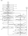
- the voltage acquisition unit 182 determines whether or not the preset determination time has arrived (step S101).
- the voltage acquisition unit 182 repeatedly executes the process of step S101 unless the determination time comes (step S101: No).
- the counting unit 184 sets the above-mentioned count value "i" of the number of times of abnormality determination to "0" (step S102). ).
- the voltage acquisition unit 182 acquires voltage value information indicating an instantaneous value of the input voltage of the power conversion unit 2 detected by each of the voltage detection units 151, 152, and 153 (step S103).
- the evaluation value calculation unit 183 calculates an evaluation value for determining whether or not there is an abnormality in the waveform of the input voltage from the instantaneous value of the input voltage indicated by the voltage value information acquired by the voltage acquisition unit 182 (step S104). After that, the abnormality presence / absence determination process for determining the presence / absence of abnormality of the input voltage waveform is executed (step S105).
- the determination unit 185 determines whether or not the evaluation value A calculated by the evaluation value calculation unit 183 is within the above-mentioned reference range, that is, whether or not the lower limit value Alth or more and the upper limit value Out or less of the reference range (step S201). .. Then, when the determination unit 185 determines that the evaluation value A is out of the reference range, that is, less than the lower limit value Alth or larger than the upper limit value Out (step S201: No), the counting unit 184 sets the number of times of abnormality determination M to "1". "Increment only (step S202). On the other hand, when the determination unit 185 determines that the evaluation value A is within the reference range (step S201: Yes), the counting unit 184 initializes the abnormality presence determination number M to “0” (step S203).
- step S106 determines whether or not the number of times of abnormality determination M is “1” or more.
- step S106: No the process of step S101 is executed again.
- step S107: Yes the voltage acquisition unit 182 determines whether or not the determination time has arrived.
- the voltage acquisition unit 182 repeatedly executes the process of step S108 unless the determination time comes (step S107: No).
- step S107 when the voltage acquisition unit 182 determines that the determination time has come (step S107: Yes), the voltage value indicating the instantaneous value of the input voltage of the power conversion unit 2 detected by each of the voltage detection units 131, 132, 133. Acquire information (step S108). Subsequently, the evaluation value calculation unit 183 calculates an evaluation value for determining whether or not there is an abnormality in the waveform of the input voltage from the instantaneous value of the input voltage indicated by the voltage value information acquired by the voltage acquisition unit 182 (step S109). After that, an abnormality presence / absence determination process for determining the presence / absence of abnormality of the input voltage waveform is executed (step S110).
- step S111 determines whether or not the first determination period has elapsed.
- step S111: No determines whether or not the first determination period has not elapsed.
- step S111: Yes determines whether or not the abnormality presence determination number M is equal to or greater than the above-mentioned first abnormality existence determination threshold M1th.
- step S112 determines that the number of times of abnormality presence determination M is less than the first threshold value of the number of times of abnormality presence determination M1th (step S112: No)
- the process of step S101 is executed again.
- the command unit 181 opens the mechanical relays 111A, 121A, 131A.
- the open command signal for setting the state is output to the mechanical relays 111A, 121A, and 131A (step S113).
- the voltage acquisition unit 182 determines whether or not the determination time has arrived (step S114).
- the voltage acquisition unit 182 repeatedly executes the process of step S114 unless the determination time comes (step S114: No).
- step S114: Yes when the voltage acquisition unit 182 determines that the determination time has arrived (step S114: Yes), as shown in FIG. 6, the input voltage of the power conversion unit 2 detected by each of the voltage detection units 131, 132, 133 is The voltage value information indicating the instantaneous value of is acquired (step S115).
- the evaluation value calculation unit 183 calculates an evaluation value for determining whether or not there is an abnormality in the waveform of the input voltage from the instantaneous value of the input voltage indicated by the voltage value information acquired by the voltage acquisition unit 182 (step S116).
- an abnormality presence / absence determination process for determining the presence / absence of abnormality of the input voltage waveform is executed (step S117).
- step S118 determines whether or not the second determination period has elapsed.
- step S118: No the process of step S114 of FIG. 4 is executed again.
- step S118: Yes the abnormality presence determination number M is equal to or greater than the above-mentioned second abnormality existence determination threshold M2th. Whether or not it is determined (step S119).
- step S119: No it is assumed that the determination unit 185 determines that the number of times of abnormality presence determination M is less than the second abnormality presence determination number threshold value M2th (step S119: No).
- step S120 the command unit 181 outputs a closing command signal for closing the mechanical relays 111A, 121A, 131A again to the mechanical relays 111A, 121A, 131A (step S120). Subsequently, the process of step S101 is executed again.
- the command unit 181 determines that the number of times of abnormality presence determination M is equal to or greater than the second abnormality presence determination number threshold value M2th (step S119: Yes).
- the command unit 181 outputs an off command signal for turning off the semiconductor switches 112A, 122A, 132A to the semiconductor switches 112A, 122A, 132A (step S121).
- the command unit 181 outputs an ON command signal for turning on the semiconductor switches 112B, 122B, 132B to the semiconductor switches 112B, 122B, 132B.
- the command unit 181 outputs an on command signal for turning on the mechanical relays 111B, 121B, 131B to the mechanical relays 111B, 121B, 131B (step S122). Then, the switch control process ends.
- the operation of the switching module 1 according to the present embodiment will be described while comparing with the operation of the switching module according to the comparative example.
- the hardware configuration of the switching module according to the comparative example is the same as that of the switching module 1, and the content of the switching control process executed by the control unit 18 is different.
- the operation of the switching module according to the comparative example will be described.
- the power supply PB1 is the standby power supply, that is, the mechanical relays 111A, 121A, 131A are all closed, and the semiconductor switches 112A, 122A, 132A are all on. Suppose there is. As shown in FIG.
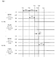
- the control unit 18 of the switching module determines whether or not there is an abnormality in the waveform of the input voltage during the preset determination period dT91.
- the determination period dT91 is set to a length sufficient to accurately determine the presence or absence of an abnormality in the waveform of the input voltage, and is set to, for example, the same length as the above-mentioned second determination period. Then, when the control unit 18 determines that an abnormality has occurred in the waveform of the input voltage at the time T92 after the determination period dT91 has elapsed from the time T91, the control unit 18 outputs an open command signal to the mechanical relays 111A, 121A, and 131A.
- the mechanical relays 111A, 121A, and 131A are actually opened at the time T93 after the response delay time dT2 has elapsed from the time T92 when the open command signal was output.
- the response delay time dT2 is determined by the performance of the mechanical relays 111A, 121A, and 131A, and is, for example, about 4 msec.
- the control unit 18 outputs an off command signal to the semiconductor switches 112A, 122A, and 132A at a time T94 when a preset standby time dT3 has elapsed from the time T92 when it is determined that an abnormality has occurred in the waveform of the input voltage.
- the standby time dT3 is set longer than the response delay time dT2 of the mechanical relays 111A, 121A, and 131A described above, and is set to, for example, 5 msec.
- the control unit 18 outputs the closing command signal to the mechanical relays 111B, 121B, 131B at the time T95 after the dead time dT4 set in advance has elapsed from the time T94, and outputs the on command signal to the semiconductor switch 112B. , 122B, 132B.
- the semiconductor switches 112B, 122B, and 132B are turned on when the on command signal is input.
- the mechanical relays 111B, 121B, and 131B are actually closed at the time T96 after the response delay time dT2 has elapsed from the time T95.
- the switching module according to the comparative example when an abnormality occurs in the waveform of the input voltage to the power conversion unit 2, the power supply source to the power conversion unit 2 is reached after the above-mentioned determination time has arrived. It takes a time corresponding to the sum of the determination period dT91, the standby time dT3, the dead time dT4, and the response delay time dT2 until the power supply PB1 is switched to.
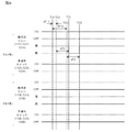
- the control unit 18 of the switching module 1 determines whether or not there is an abnormality in the waveform of the input voltage during the first determination period dT11 when the determination time arrives at the time T1.
- the first determination period dT11 is set to a length at which it can be determined that an abnormality may have occurred in the waveform of the input voltage to the power conversion unit 2, and is set to, for example, 1 msec.
- the open command signal is sent to the mechanical relays 111A, 121A, 131A. Output to.
- the control unit 18 determines that an abnormality has occurred in the waveform of the input voltage at the time T3 after the second determination period dT12 has elapsed from the time T1 after outputting the open command signal.
- the second determination period dT11 is set to, for example, 4 msec, which is the same length as the determination period according to the above-mentioned comparative example.
- the control unit 18 avoids outputting the closing command signal to the mechanical relays 111A, 121A, and 131A.
- the mechanical relays 111A, 121A, and 131A are actually opened at the time T4 after the response delay time dT2 has elapsed from the time T2 at which the open command signal is output.
- the control unit 18 outputs an off command signal to the semiconductor switches 112A, 122A, and 132A at the time T5 when the standby time dT3 has elapsed from the time T2 when it is determined that an abnormality has occurred in the waveform of the input voltage, and the semiconductor switch. 112A, 122A, and 132A are turned off.
- the control unit 18 outputs the closing command signal to the mechanical relays 111B, 121B, 131B at the time T6 after the dead time dT4 has elapsed from the time T5, and outputs the on command signal to the semiconductor switches 112B, 122B, 132B. Output to.
- the semiconductor switches 112B, 122B, and 132B are turned on when the on command signal is input.
- the mechanical relays 111B, 121B, and 131B are actually closed at the time T7 after the response delay time dT2 has elapsed from the time T6.
- the switching module 1 when an abnormality occurs in the waveform of the input voltage to the power conversion unit 2, the power supply source to the power conversion unit 2 is transferred to the power supply PB1 after the above-mentioned determination time has arrived. It takes time corresponding to the sum of the first determination period dT11, the standby time dT3, the dead time dT4, and the response delay time dT2 until the switching is performed.
- the length of the second determination period dT12 is the same as the length of the determination period dT91 according to the comparative example
- the power conversion unit 2 is moved to the power conversion unit 2 after the determination time has arrived, as compared with the switching module according to the comparative example.
- the time required to switch the power supply source to the power supply PB1 is shortened by the time ⁇ T corresponding to the difference between the second determination period dT12 and the first determination period dT11.
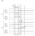
- the control unit 18 determines whether or not there is an abnormality in the waveform of the input voltage during the first determination period dT11.
- the control unit 18 transmits the open command signal to the mechanical relays 111A and 121A. Output to 131A.
- control unit 18 determines that the waveform of the input voltage is normal at the time T23 after the second determination period dT12 has elapsed from the time T21 after outputting the open command signal. In this case, the control unit 18 outputs the closing command signal to the mechanical relays 111A, 121A, and 131A. At this time, the control unit 18 avoids outputting the off command signal to the semiconductor switches 112A, 122A, 132A. As a result, the semiconductor switches 112A, 122A, and 132A remain on.
- the mechanical relays 111A, 121A, and 131A are once opened at the time T24 after the response delay time dT2 has elapsed from the time T22 when the open command signal is output. After that, the mechanical relays 111A, 121A, and 131A are closed again at the time T25 after the response delay time dT2 has elapsed from the time T23 when the closing command signal was output. In this way, the switching module 1 supplies power to the power conversion unit 2 when a sudden abnormality has occurred in the waveform of the input voltage to the power conversion unit 2 and no constant abnormality has occurred. Prevents accidentally switching from the power supply PA1 to the power supply PB1.
- the control unit 18 determines that the waveform of the input voltage to the power conversion unit 2 during the first determination period is abnormal, the machine An open command signal for opening the type relays 111A, 121A, 131A is output to the mechanical relays 111A, 121A, 131A.
- the control unit 18 gives a closing command for closing the mechanical relays 111A, 121A, 131A.
- the signal is output to the mechanical relays 111A, 121A and 131A.
- the control unit 18 determines that the waveform of the input voltage during the second determination period is abnormal, the control unit 18 outputs the closing command signal to the mechanical relay 111B, which is in an open state different from the mechanical relays 111A, 121A, 131A.
- the power supply electrically connected to the power conversion unit 2 is changed from the power supply PA1 to the power supply PB1.
- the open command signal is output to the mechanical relays 111A, 121A, 131A when the first determination period shorter than the second determination period elapses, so that the mechanical type
- the start time of the operation for opening the relays 111A, 121A, and 131A can be accelerated. Therefore, when an abnormality occurs in the waveform of the input voltage, the time required for switching the power supplies PA1 and PB1 as the power supply source can be shortened.
- control unit 18 receives the input voltage detected by the voltage detection units 151, 152, and 153 during the preset third determination period each time the preset determination time arrives. Based on the instantaneous value, a pre-determination for determining whether or not the waveform of the input voltage to the power conversion unit 2 is abnormal is executed. The length of the third determination period is about several ⁇ sec. Then, when the control unit 18 determines that the waveform of the input voltage is abnormal in the pre-determination, it determines whether or not the waveform of the input voltage is abnormal during the first determination period. On the other hand, the control unit 18 repeats the pre-determination as long as it determines that the waveform of the input voltage is normal in the pre-determination.
- control unit 18 determines whether or not the waveform of the input voltage in the subsequent first determination period is abnormal only when it is determined that the waveform of the input voltage is abnormal in the pre-determination. As a result, the control unit 18 does not need to store the information indicating the waveform of the input voltage during the first determination period in the past, so that the storage capacity required for the control unit 18 can be reduced accordingly. Can be done. Further, the control unit 18 can omit the process of analyzing the information indicating the waveform of the input voltage during the first determination period in the past and determining whether or not an abnormality has occurred in the waveform. By the minute, the processing to be executed by the control unit 18 can be simplified.
- control unit 18 continues the state in which the evaluation value calculated from the instantaneous value of the input voltage is out of the preset reference range during the first determination period for the preset reference period. Then, it is determined that the waveform of the input voltage during the first determination period is abnormal. As a result, the control unit 18 does not need to store the information indicating the waveform of the input voltage during the first determination period in the past, so that the storage capacity required for the control unit 18 can be reduced accordingly. Can be done.
- the power supply system includes a switching module 2001 and a power conversion unit 2002, and receives AC power from the single-phase power supply PA2 or power supply PB2 to supply DC power to the load LZ. It may be a thing.
- the same reference numerals as those in FIG. 1 are attached to the same configurations as those in the embodiment.
- the power conversion unit 2002 has one AC-DC converter 2021.
- the AC-DC converter 2021 has the same configuration as the AC-DC converters 21, 22, and 23 described in the embodiment.
- the switching module 2001 includes four mechanical relays 111A, 121A, 111B, 121B and four semiconductor switches 112A, 122A, 112B, 122B connected between each of the two power supplies PA2 and PB2 and the power conversion unit 2002. , And a voltage detection unit 2015. Further, the switching module 2001 includes four input terminals te21A, te22A, te21B and te22B, and two output terminals te24 and te25.
- the power lines L21A and L22A connected to the power supply PA2 are connected to the input terminals te21A and te22A, respectively, and the power lines L21B and L22B connected to the standby power supply PB2 are connected to the input terminals te21B and te22B, respectively. ing. Further, a pair of input terminals of the AC-DC converter 2021 are connected between the output terminals te24 and te25.
- the voltage detection unit 2015 is the same as the voltage detection units 151, 152, and 153 described in the embodiment, and is connected between the output terminals te24 and te25, and the voltage between the output terminals te24 and te25, that is, AC-DC. The input voltage to the converter 2021 is detected.
- the control unit 2018 controls the open / closed state of each of the four mechanical relays 111A, 121A, 111B, and 121B so that any one of the two power supplies PA2 and PB2 is electrically connected to the power conversion unit 2002. To do.
- the control unit 2018 also controls the on / off states of the semiconductor switches 112A, 122A, 112B, and 122B, respectively.
- the control unit 18 has a microcomputer and a memory as in the embodiment, and the microcomputer functions as a command unit 2181, a voltage acquisition unit 182, an evaluation value calculation unit 2183, a counting unit 184, and a determination unit 185. Further, the memory is provided with a reference value storage unit 2191 and a normal waveform storage unit 2192 that stores information indicating a normal waveform of the input voltage.
- the command unit 2181 controls the open / closed state of the open command signal or the close command signal by outputting the open command signal or the close command signal to the mechanical relays 111A, 121A, 111B, 121B. Further, the command unit 2141 controls the on / off state by outputting the on command signal or the off command signal to the semiconductor switches 112A, 122A, 112B, and 122B.
- the voltage acquisition unit 182 acquires information indicating an instantaneous value of the input voltage to the power conversion unit 2002 detected by the voltage detection unit 2016.
- the evaluation value calculation unit 2183 calculates the absolute value of the difference voltage between the above-mentioned normal waveform of the input voltage and the actual waveform of the input voltage to the power conversion unit 2002 as the evaluation value.
- the determination unit 185 has an abnormal input voltage waveform if the evaluation value calculated by the evaluation value calculation unit 183 is out of the above-mentioned reference range in the pre-determination, as in the embodiment. Is determined. Further, if the determination unit 185 continues for the preset first reference period in a state where the above-mentioned evaluation value is out of the preset reference range during the first determination period, the input voltage during the first determination period It is determined that the waveform of is abnormal. Further, when the determination unit 185 determines that the waveform of the input voltage during the first determination period is abnormal, the determination unit 185 is preset in a state where the above-mentioned evaluation value is out of the above-mentioned reference range during the second determination period. If it continues only for the second reference period, it is determined that the waveform of the input voltage during the second determination period is abnormal.
- the command unit 2181 opens to open the mechanical relays 111A and 121A in the closed state.
- the command signal is output to the mechanical relays 111A and 121A.
- the mechanical relays 111A and 121A to which the open command signal is output are closed.
- the closing command signal is output to the mechanical relays 111A and 121A.
- the command unit 2181 outputs the open command signal
- the command unit 2181 determines that the waveform of the input voltage during the second determination period is abnormal
- the command unit 2181 outputs the close command signal of the close command signal.
- the output to the above mechanical relays 111A, 121A, 131A is avoided.
- the command unit 2181 turns off the semiconductor switches 112A and 122A by outputting an off command signal to the semiconductor switches 112A and 122A.
- the power supply source to the power conversion unit 2002 is changed from the power supply PA2 to the power supply PB2.
- the time required for switching can be shortened.
- the power supply system receives the supply of three-phase AC power from the power supply PA1 or the power supply PB1 formed by ⁇ -connecting three AC power supplies and supplies DC power to the load LZ.
- the present invention is not limited to this, and as shown in FIG. 12, for example, as shown in FIG. 12, the power supply system receives the supply of three-phase AC power from the power supply PA3 or the power supply PB3 formed by Y-connecting three AC power supplies, and direct current power to the load LZ. May be supplied.
- FIG. 12 the same reference numerals as those in FIG. 1 are attached to the same configurations as those in the embodiment.
- the power supply PA3 supplies three-phase alternating current to the power supply system via four power lines L31A, L32A, L33A, and L34A. Further, the power supply PB3 supplies three-phase alternating current to the power supply system via the four power lines L31B, L32B, L33B, and L34B.
- the switching module 3001 includes eight mechanical relays 111A, 121A, 131A, 141A, 111B, 121B, 131B, 141B and eight semiconductor switches connected between each of the two power supplies PA3 and PB3 and the power conversion unit 2. It includes 112A, 122A, 132A, 142A, 112B, 122B, 132B, 142B, and voltage detection units 3151, 3152, and 3153.
- the mechanical relays 141A and 141B have the same configurations as the mechanical relays 111A, 121A, 131A, 111B, 121B and 131B.
- the semiconductor switches 142A and 142B have the same configurations as the semiconductor switches 112A, 122A, 132A, 112B, 122B and 132B.
- the switching module 3001 includes eight input terminals te31A, te32A, te33A, te34A, te31B, te32B, te33B, te34B and four output terminals te35, te36, te37, te38.
- Power lines L31A, L32A, L33A, and L34A connected to the power supply PA3 are connected to the input terminals te31A, te32A, te33A, and te34A, respectively, and standby power supplies are connected to the input terminals te31B, te32B, te33B, and te34B, respectively.
- the power lines L31B, L32B, L33B, and L34B connected to the PB3 are connected.
- a pair of input terminals of the AC-DC converter 21 are connected between the output terminals te35 and te38, and a pair of input ends of the AC-DC converter 22 are connected between the output terminals te36 and te38.
- a pair of input terminals of the AC-DC converter 23 are connected between the output terminals te37 and te38.
- the voltage detection unit 3151 is connected between the output terminals te35 and te38, and detects the voltage between the output terminals te35 and te38, that is, the input voltage to the AC-DC converter 21.
- the voltage detection unit 3152 is connected between the output terminals te36 and te38, and detects the voltage between the output terminals te36 and te38, that is, the input voltage to the AC-DC converter 22.
- the voltage detection unit 3153 is connected between the output terminals te37 and te38, and detects the voltage between the output terminals te37 and te38, that is, the input voltage to the AC-DC converter 23.
- the control unit 3018 has eight mechanical relays 111A, 121A, 131A, 141A, 111B, 121B, 131B so that any one of the two power supplies PA3 and PB3 is electrically connected to the power conversion unit 2. , 141B, respectively, control the open / closed state.
- the control unit 3018 also controls the on / off states of the semiconductor switches 112A, 122A, 132A, 142A, 112B, 122B, 132B, and 142B, respectively.
- the control unit 3018 has, for example, a microcomputer and a memory as in the embodiment, and the microcomputer functions as a command unit 3181, a voltage acquisition unit 182, an evaluation value calculation unit 183, a counting unit 184, and a determination unit 185. Further, the memory is provided with a reference value storage unit 191.
- the command unit 3181 controls the open / closed state of the open command signal or the close command signal by outputting the open command signal or the close command signal to the mechanical relays 111A, 121A, 131A, 141A, 111B, 121B, 131B, 141B. Further, the command unit 3181 controls the on / off state by outputting the on command signal or the off command signal to the semiconductor switches 112A, 122A, 132A, 142A, 112B, 122B, 132B, 142B.
- the voltage acquisition unit 182 acquires information indicating an instantaneous value of the input voltage to the power conversion unit 2 detected by the voltage detection units 3151, 3152, and 3153.
- the evaluation value calculation unit 183 calculates an evaluation value that reflects, for example, the sum of squares of the instantaneous values of the input voltages of the three phases to the power conversion unit 2, as in the embodiment.
- the determination unit 185 determines that the waveform of the input voltage is abnormal if the evaluation value calculated by the evaluation value calculation unit 183 is out of the above-mentioned reference range in the pre-determination. Further, if the determination unit 185 continues for the preset first reference period in a state where the above-mentioned evaluation value is out of the preset reference range during the first determination period, the input voltage during the first determination period It is determined that the waveform of is abnormal. Further, when the determination unit 185 determines that the waveform of the input voltage during the first determination period is abnormal, the determination unit 185 is preset in a state where the above-mentioned evaluation value is out of the above-mentioned reference range during the second determination period. If it continues only for the second reference period, it is determined that the waveform of the input voltage during the second determination period is abnormal.
- the command unit 3181 opens the mechanical relays 111A, 121A, 131A, 141A in the closed state.
- the open command signal is output to the mechanical relays 111A, 121A, 131A, and 141A.
- the command unit 181 outputs the open command signal, if it determines that the waveform of the input voltage during the second determination period is normal, the command unit 181 outputs the close command signal to the mechanical relays 111A, 121A, 131A, 141A. To do.
- the command unit 3181 outputs the open command signal
- the mechanical relays 111A and 121A of the close command signal are used. , 131A, 141A are avoided.
- the command unit 3181 turns off the semiconductor switches 112A, 122A, 132A, 142A by outputting the off command signal to the semiconductor switches 112A, 122A, 132A, 142A.
- power is supplied to the power conversion unit 2 in a power supply system that receives supply of three-phase AC power from the power supply PA3 or power supply PB3 that is Y-connected to the AC power supply and supplies DC power to the load LZ.
- the time required to switch the source from the power supply PA3 to the power supply PB3 can be shortened.
- the control unit 18 has a determination period setting unit (not shown) that extends the first determination period by a preset unit period according to the status of determination by the determination unit 185 for the presence or absence of an abnormality. It may be. That is, the control unit 18 updates the length of the first determination period to a longer time when the determination result in the first determination period and the determination result in the second determination period are different from each other for a predetermined number of times. There may be. In this case, the counting unit 184 outputs an open command signal to the mechanical relays 111A, 121A, 131A, 111B, 121B, 131B after the first determination period during the preset extension determination period, and then the second determination period.
- the determination unit 185 determines that the number of times of opening / closing repetition has reached the preset extension determination reference number or more, the determination period setting unit extends the first determination period by a preset unit period. There may be.
- the determination unit 185 determines that the waveform of the input voltage to the power conversion unit 2 during the first determination period is abnormal during the preset extension determination period, the above-mentioned input in the second determination period When the determination that the voltage waveform is normal is repeated for a preset extension determination reference number or more, the first determination period may be extended by a preset unit period.
- step S114 the control unit 18 executes a series of processes from steps S101 to S114 shown in FIG.
- step S114 it is assumed that the voltage acquisition unit 182 determines whether or not the determination time has come (step S114: Yes).
- step S115 a series of processes from steps S115 to S119 are executed.
- step S119 it is assumed that the determination unit 185 determines that the number of times of abnormality presence determination M is less than the second abnormality presence determination number threshold value M2th (step S119: No).
- the command unit 181 outputs the closing command signal to the mechanical relays 111A, 121A, 131A (step S122).
- the counting unit 184 increments the number of times of repeating opening and closing by "1" (step S401).
- the determination unit 185 determines whether or not the preset extension determination period has elapsed (step S402).
- the extension determination period can be set to, for example, one day or one year.
- the counting unit 184 initializes the number of open / close repetitions to "0" (step S403), and is shown again in FIG. The process of step S101 is executed.
- step S119 determines in step S119 that the number of times the abnormality has been determined M is equal to or greater than the second threshold value M2th for the number of times the abnormality has been determined (step S119: Yes), the processes after step S120 are executed.
- step S404 determines whether or not the opening / closing repetition number P is equal to or greater than the extension determination reference number P1th.
- step S404 determines that the number of times of opening / closing repetition P is less than the extension determination reference number of times P1th.
- step S404: Yes when the determination unit 185 determines that the opening / closing repetition number P is equal to or greater than the extension determination reference number P1th (step S404: Yes), the first determination period dT11 is set in advance for the first determination period. It is determined whether or not it is equal to or less than the upper limit value dT11max (step S405). When the determination unit 185 determines that the first period dT11 exceeds the first period upper limit value dT11max (step S405: No), the process of step S101 shown in FIG. 4 is executed again. Returning to FIG.
- step S405 when the determination unit 185 determines that the first period dT11 is equal to or less than the first period upper limit value dT11max (step S405: Yes), the determination period setting unit sets the first determination period dT11 in advance. It is extended by the set unit period (step S406). After that, the process of step S101 shown in FIG. 4 is executed again.
- the determination period setting unit outputs the open command signal to the mechanical relays 111A, 121A, 131A, 111B, 121B, 131B after the first determination period, and then opens the close command signal after the second determination period.
- the length of the first determination period dT11 is set to an appropriate length so that the operation of outputting the command signal to the mechanical relays 111A, 121A, 131A, 111B, 121B, 131B to which the command signal is output is reduced.
- the frequency of opening and closing of the mechanical relays 111A, 121A, 131A, 111B, 121B, 131B can be reduced, the contact wear of the mechanical relays 111A, 121A, 131A, 111B, 121B, 131B can be suppressed. it can.
- control unit 18 may extend the first determination period by a preset unit period according to the temperature of each of the semiconductor switches 121A, 122A, 132A, 121B, 122B, 132B. ..
- the switching module 5001 detects the temperatures of the semiconductor switches 121A, 122A, 132A, 121B, 122B, and 132B, respectively. It includes 5113B, 5123B, and 5133B.
- the control unit 5018 has a temperature acquisition unit 5186 that acquires information indicating the temperature detected by the temperature detection units 5113A, 5123A, 5133A, 5113B, 5123B, and 5133B, and a temperature acquisition unit 5186 that acquires the temperature indicated by the information acquired by the temperature acquisition unit 5186. It has a determination period setting unit 5187 that extends the first determination period based on the above. Further, the determination unit 5185 executes the process described in the embodiment, and any one of the temperatures detected by the temperature detection units 5113A, 5123A, 5133A, 5113B, 5123B, and 5133B is equal to or higher than the preset reference temperature. It is determined whether or not it is.
- the reference temperature is determined based on the temperature performance of the semiconductor switches 121A, 122A, 132A, 121B, 122B, 132B, and is set to, for example, 125 ° C.
- the determination period setting unit 5187 determines that at least one of the temperatures detected by the temperature detection units 5113A, 5123A, 5133A, 5113B, 5123B, and 5133B by the determination unit 5185 is equal to or higher than the reference temperature, the first determination is made.
- the period is extended by a preset unit period.
- the length of the unit period is set to, for example, 0.5 msec.
- the determination unit 5185 determines whether or not any one of the temperatures Th detected by the temperature detection units 5113A, 5123A, 5133A, 5113B, 5123B, and 5133B is equal to or higher than the reference temperature Thh (step S501).
- step S501: No the determination unit 5185 performs the process of step S501. Execute repeatedly. On the other hand, it is assumed that the determination unit 5185 determines that any one of the temperatures Th detected by the temperature detection units 5113A, 5123A, 5133A, 5113B, 5123B, and 5133B is equal to or higher than the reference temperature Thh (step S501: Yes).
- the determination unit 5185 determines whether or not the first determination period dT11 is equal to or less than the preset first determination period upper limit value dT11max (step S502).
- the determination unit 5185 executes the process of step S501 again.
- the determination period setting unit 5187 sets the first determination period dT11 in advance. It is extended by a unit period (step S503). After that, the process of step S501 is executed again.
- the power supply system receives the supply of AC power from the power supply PA1 or the power supply PB1 which is a three-phase AC power supply and supplies DC power to the load LZ.
- the present invention is not limited to this, and as shown in FIG. 16, for example, even if the power supply system boosts or lowers the DC power supplied from the DC power supply PA6 or the power supply PB6 and supplies it to the load LZ. Good.
- FIG. 16 the same reference numerals as those in FIG. 10 are attached to the same configurations as those of the modified examples described with reference to FIG.
- the power supplies PA6 and PB6 are, for example, storage batteries.
- the power supply system includes a switching module 6001 and a power conversion unit 6002, and the power conversion unit 6002 includes a DC-DC converter 6021.
- the control unit 6018 of the switching module 6002 has an evaluation value calculation unit 6183 and a reference value storage unit 6191.
- the reference value storage unit 6191 contains information indicating a reference voltage value with respect to the voltage values output from the power supplies PA6 and PB6, and a voltage value and a reference voltage value of the input voltage to the power conversion unit 6002 detected by the voltage detection unit 6015. Information indicating the difference threshold with respect to the absolute value of the difference voltage of is stored.
- the evaluation value calculation unit 6183 calculates the absolute value of the difference voltage between the reference voltage value and the voltage value of the input voltage to the power conversion unit 2 as the evaluation value.
- the command unit 2181 opens to open the mechanical relays 111A and 121A in the closed state.
- the command signal is output to the mechanical relays 111A and 121A.
- the mechanical relays 111A and 121A to which the open command signal is output are closed.
- the closing command signal is output to the mechanical relays 111A and 121A.
- the command unit 2181 outputs the open command signal
- the command unit 2181 determines that the waveform of the input voltage during the second determination period is abnormal
- the command unit 2181 outputs the close command signal of the close command signal.
- the output to the above mechanical relays 111A, 121A, 131A is avoided.
- the command unit 2181 turns off the semiconductor switches 112A and 122A by outputting an off command signal to the semiconductor switches 112A and 122A.
- the power supply source to the power conversion unit 6002 is supplied from the power supply PA6.
- the time required to switch to PB6 can be shortened.
- the number of times the control unit 18 determines that the evaluation value calculated from the input voltage to the power conversion unit 2 is continuously out of the reference range during the first determination period is the first.
- An example of determining that the waveform of the input voltage is abnormal when the number of times of abnormality determination exceeds the threshold value has been described.
- the ratio of the evaluation value calculated from the input voltage to the power conversion unit 2 out of the reference range is set in advance. If it is equal to or more than the set reference ratio, it may be determined that the waveform of the input voltage during the first determination period is abnormal.
- control unit 18 determines whether or not there is an abnormality in the waveform of the input voltage during the first determination period when it is determined to be abnormal in the pre-determination.
- the present invention is not limited to this, and the control unit 18 stores, for example, the history of the instantaneous value of the past input voltage to the power conversion unit 2 in the memory, and the time when the first determination period is traced back from the present time to the past. It may be used to determine whether or not the waveform of the input voltage during the period between the present time and the present time is abnormal.
- control unit 18 determines that the waveform of the input voltage during the first determination period retroactive from the present time is abnormal, when the second determination period elapses from the time retroactive by the first determination period from the present time. , It may be determined whether or not the waveform of the input voltage during the second determination period is abnormal.
- the configuration in which the switching module 1 includes the semiconductor switches 112A, 122A, 132A, 112B, 122B, 132B has been described, but the configuration is not necessarily limited to the configuration including the semiconductor switches 112A, 122A, 132A, 112B, 122B, 132B. Not done.
- the switching module may have a configuration in which the semiconductor switches 112A, 122A, 132A, 112B, 122B, and 132B are omitted.
- the present invention is suitable for a power supply system for a server.
Landscapes
- Engineering & Computer Science (AREA)
- Power Engineering (AREA)
- Business, Economics & Management (AREA)
- Emergency Management (AREA)
- Inverter Devices (AREA)
- Dc-Dc Converters (AREA)
- Stand-By Power Supply Arrangements (AREA)
- Relay Circuits (AREA)
- Supply And Distribution Of Alternating Current (AREA)
- Rectifiers (AREA)
Priority Applications (2)
| Application Number | Priority Date | Filing Date | Title |
|---|---|---|---|
| JP2021567207A JP7380712B2 (ja) | 2019-12-25 | 2020-12-10 | スイッチングモジュールおよび電源システム |
| US17/847,354 US11909256B2 (en) | 2019-12-25 | 2022-06-23 | Switching module and power supply system |
Applications Claiming Priority (2)
| Application Number | Priority Date | Filing Date | Title |
|---|---|---|---|
| JP2019-234817 | 2019-12-25 | ||
| JP2019234817 | 2019-12-25 |
Related Child Applications (1)
| Application Number | Title | Priority Date | Filing Date |
|---|---|---|---|
| US17/847,354 Continuation US11909256B2 (en) | 2019-12-25 | 2022-06-23 | Switching module and power supply system |
Publications (1)
| Publication Number | Publication Date |
|---|---|
| WO2021131741A1 true WO2021131741A1 (ja) | 2021-07-01 |
Family
ID=76575472
Family Applications (1)
| Application Number | Title | Priority Date | Filing Date |
|---|---|---|---|
| PCT/JP2020/046011 Ceased WO2021131741A1 (ja) | 2019-12-25 | 2020-12-10 | スイッチングモジュールおよび電源システム |
Country Status (3)
| Country | Link |
|---|---|
| US (1) | US11909256B2 (https=) |
| JP (1) | JP7380712B2 (https=) |
| WO (1) | WO2021131741A1 (https=) |
Cited By (2)
| Publication number | Priority date | Publication date | Assignee | Title |
|---|---|---|---|---|
| WO2022149321A1 (ja) * | 2021-01-07 | 2022-07-14 | 株式会社村田製作所 | スイッチングモジュール |
| JP7690248B1 (ja) * | 2025-03-24 | 2025-06-10 | エクセン株式会社 | 3相電線用異常検出装置 |
Families Citing this family (2)
| Publication number | Priority date | Publication date | Assignee | Title |
|---|---|---|---|---|
| JP7171946B1 (ja) * | 2021-06-02 | 2022-11-15 | 東芝三菱電機産業システム株式会社 | 電源装置 |
| JP7477941B1 (ja) * | 2022-10-06 | 2024-05-02 | 株式会社Tmeic | 電源装置 |
Citations (3)
| Publication number | Priority date | Publication date | Assignee | Title |
|---|---|---|---|---|
| JPH0543731U (ja) * | 1991-11-13 | 1993-06-11 | 株式会社ユアサコーポレーシヨン | 制御回路用給電装置 |
| WO2018043319A1 (ja) * | 2016-09-05 | 2018-03-08 | 株式会社村田製作所 | 電源システム |
| JP2018198478A (ja) * | 2017-05-23 | 2018-12-13 | 富士電機株式会社 | 電源装置 |
Family Cites Families (2)
| Publication number | Priority date | Publication date | Assignee | Title |
|---|---|---|---|---|
| JP5118913B2 (ja) * | 2007-07-24 | 2013-01-16 | トヨタ自動車株式会社 | 電源システムおよびそれを備えた電動車両ならびに電源システムの制御方法 |
| EP2439097B1 (en) * | 2009-06-02 | 2015-11-11 | Toyota Jidosha Kabushiki Kaisha | Power supply system of electric vehicle and control method thereof |
-
2020
- 2020-12-10 JP JP2021567207A patent/JP7380712B2/ja active Active
- 2020-12-10 WO PCT/JP2020/046011 patent/WO2021131741A1/ja not_active Ceased
-
2022
- 2022-06-23 US US17/847,354 patent/US11909256B2/en active Active
Patent Citations (3)
| Publication number | Priority date | Publication date | Assignee | Title |
|---|---|---|---|---|
| JPH0543731U (ja) * | 1991-11-13 | 1993-06-11 | 株式会社ユアサコーポレーシヨン | 制御回路用給電装置 |
| WO2018043319A1 (ja) * | 2016-09-05 | 2018-03-08 | 株式会社村田製作所 | 電源システム |
| JP2018198478A (ja) * | 2017-05-23 | 2018-12-13 | 富士電機株式会社 | 電源装置 |
Cited By (4)
| Publication number | Priority date | Publication date | Assignee | Title |
|---|---|---|---|---|
| WO2022149321A1 (ja) * | 2021-01-07 | 2022-07-14 | 株式会社村田製作所 | スイッチングモジュール |
| JPWO2022149321A1 (https=) * | 2021-01-07 | 2022-07-14 | ||
| JP7276630B2 (ja) | 2021-01-07 | 2023-05-18 | 株式会社村田製作所 | スイッチングモジュール |
| JP7690248B1 (ja) * | 2025-03-24 | 2025-06-10 | エクセン株式会社 | 3相電線用異常検出装置 |
Also Published As
| Publication number | Publication date |
|---|---|
| JPWO2021131741A1 (https=) | 2021-07-01 |
| US20220320893A1 (en) | 2022-10-06 |
| JP7380712B2 (ja) | 2023-11-15 |
| US11909256B2 (en) | 2024-02-20 |
Similar Documents
| Publication | Publication Date | Title |
|---|---|---|
| WO2021131741A1 (ja) | スイッチングモジュールおよび電源システム | |
| US9755528B2 (en) | AC-DC converter with output power suppression | |
| US10432108B2 (en) | Power supply system | |
| JP6730515B2 (ja) | 電力変換装置 | |
| JP2019075851A (ja) | 故障検出機能を有するモータ駆動装置 | |
| JP4247797B2 (ja) | 無停電電力供給装置 | |
| US11245337B2 (en) | Power supply device | |
| US20150357939A1 (en) | Cascaded h-bridge inverter capable of operating in bypass mode | |
| CN108666966B (zh) | 具备短路故障检测功能的变换装置及其短路故障检测方法 | |
| JP2016010290A (ja) | 電力変換装置、変換器及び電力変換装置の制御方法 | |
| JPWO2020110225A1 (ja) | 電力変換装置 | |
| US9444356B2 (en) | Power supply device and power supply switching method | |
| JP2008048485A (ja) | 直流交流変換装置、および直流交流変換装置の過電流保護方法 | |
| US20180342893A1 (en) | Power supply | |
| US8817490B2 (en) | DC-DC converter | |
| JP6354505B2 (ja) | スイッチング電源装置 | |
| CN110829571B (zh) | 高效柔性转换器 | |
| JP2018207732A (ja) | 電源システムおよび電源装置 | |
| JPWO2020137237A1 (ja) | スイッチングモジュール | |
| US11509252B2 (en) | Management of the number of active power cells of a variable speed drive | |
| JP2010051116A (ja) | スイッチング電源装置、電源システム、および電子装置 | |
| JP5264287B2 (ja) | 瞬時電圧低下補償装置 | |
| JP7612946B1 (ja) | 電力変換装置 | |
| US20240405697A1 (en) | Power conversion device and method for controlling power conversion device | |
| CN111257703B (zh) | 电源转换器中的击穿检测 |
Legal Events
| Date | Code | Title | Description |
|---|---|---|---|
| 121 | Ep: the epo has been informed by wipo that ep was designated in this application |
Ref document number: 20905957 Country of ref document: EP Kind code of ref document: A1 |
|
| ENP | Entry into the national phase |
Ref document number: 2021567207 Country of ref document: JP Kind code of ref document: A |
|
| NENP | Non-entry into the national phase |
Ref country code: DE |
|
| 122 | Ep: pct application non-entry in european phase |
Ref document number: 20905957 Country of ref document: EP Kind code of ref document: A1 |